The Pennsylvania State University. The Graduate School. Department of Energy and Mineral Engineering
|
|
|
- Annice Bell
- 5 years ago
- Views:
Transcription
1 The Pennsylvania State University The Graduate School Department of Energy and Mineral Engineering MEASUREMENT OF SELECTED PHYSICAL AND CHEMICAL PROPERTIES OF BLENDS OF COAL-BASED JET FUEL WITH DODECANE AND NORPAR-13 A Thesis in Energy and Mineral Engineering by Sidonie Guiadem 2009 Sidonie Guiadem Submitted in Partial Fulfillment of the Requirements for the Degree of Master of Science December 2009
2 The thesis of Sidonie Guiadem was reviewed and approved* by the following: Harold H. Schobert Professor of Fuel Science Thesis Advisor Jonathan P. Mathews Assistant Professor of Energy and Mineral Engineering Caroline E. Burgess Clifford Senior Research Associate at the EMS Energy Institute R. Larry Grayson Professor of Energy and Mineral Engineering Graduate Program Officer of Energy and Mineral Engineering *Signatures are on file in the Graduate School
3 iii ABSTRACT The aim of this work was to investigate the impact of blending a coal-based fuel, JP-900, with two model paraffinic fuels, dodecane and Norpar-13, on jet fuel properties. The thermal stabilities of the feedstocks and the blends were tested in the oxidative and pyrolytic regimes using microautoclave or tubing bomb reactors. Some properties, such as density, net heat of combustion, smoke point, flash point, viscosity and freezing point were also evaluated. The coal-based fuel JP-900 was produced at Intertek-PARC in Harmarville, PA, by hydrotreating and hydrogenating a blend of RCO (refined chemical oil), and LCO (light cycle oil) at 1:1 ratio by weight. For a fuel to be utilized in a jet engine, the fuel has to be thermally stable and also meet all the American Society for Testing and Materials (ASTM) requirements. All the properties evaluated were done following an ASTM standard. The study has shown that JP-900 meets the specification requirement for flash point and freezing point. But, the problem associated with high cycloalkane content in JP-900 is high density and low hydrogen content. Due to the high content of cyclic compounds in the coal-based fuel, JP-900 was blended with two models paraffinic fuels dodecane and Norpar-13 to evaluate the properties of the blends. The results from this blending are that some properties, such as density, hydrogen content and net heat of combustion, were improved. But, for the freezing point the blending did not improve the properties, because the paraffinic fuels had very high freezing points. The boiling point distribution of the samples was also evaluated under the ASTM D Models proposed in the literature were also tested on some properties such as flash point, freezing point and smoke point. The correlation
4 iv proposed by Wickey and Chittenden predicted the flash point of the JP-900/Norpar-13 blend with an average absolute error of 1.8 o C and 1.5 o C for the JP-900/dodecane mixture. For the viscosity, the model from Moharam et al. accurately predicted the kinematic viscosity of the feedstock and all the blends with an average absolute error of 0.35 cst. Except for the coal-based fuel JP-900, the Cookson et al. model accurately predicts the freeze point temperatures of the blends and the paraffinic fuels, with an average absolute error, predicted versus observed, of 1.95 o C for JP-900/Norpar-13 and 3.2ºC for the JP- 900/dodecane blend. For the sooting tendency, the model from Cookson et al. predicted accurately the smoke point of the coal-based fuel and two blends B101 and B201 with an absolute error of 1mm. Chemical compositions and structures of coal-based jet fuel were determined by GC/MS, 13 C NMR and 1 H NMR analyses. Quantitative analysis by GC/MS was used to classify chemical composition into seven groups of compounds, while NMR analysis was used to identify the aliphatic and aromatic regions of interest in this work. The results from GC/MS and NMR characterization showed significant agreement in terms of presence or non-appearance of aromatics in the fuels. The thermal stressing of the coal-based and paraffinic fuels, along with their blends, was conducted in the oxidative and the pyrolytic regimes using a 25 ml microautoclave reactor. In the oxidative regime 5 ml of sample fuels was heated at 200 o C in the presence of air. The pyrolytic stability was determined by heating 5 ml of sample at 450 o C under 100 psig of ultra-high purity N 2 for different periods of time. The results from these stressing showed that JP-900 was thermally stable at both temperatures, 200 o C and at 450 o C for a period of 4h. The extents of fuel degradation in
5 v terms of liquid depletion and gas formation in the pyrolytic regime were higher with the paraffinic fuels than with the coal-based fuel. In the oxidative regime the addition of paraffinic fuels to JP-900 did not show any significant difference in the results, but in the pyrolytic regime, blending dodecane or Norpar-13 into JP-900 decreased the thermal stability of the blends.
6 vi TABLE OF CONTENTS LIST OF FIGURES... viii LIST OF TABLES... xi ACKNOWLEDGEMENTS... xiii Chapter 1 Introduction Introduction Objectives... 3 Chapter 2 Literature Review Aviation Fuels Specification of Jet Fuel for U.S. Aircraft and Properties Testing Fuel Density Volatility Properties Fluidity Properties Combustion Properties Thermal Stability Thermal Oxidative Stability Role of Antioxidant and Additives Pyrolytic Stability Chapter 3 Experimental Procedures Production of Coal-Based JP Samples Characterization of the Fuel Samples GC/MS Analysis Simulated Distillation Gas Chromatography NMR Analysis Physical Properties Testing Density Specific Gravity, API Flash Point Viscosity Freezing Point Heat of Combustion Hydrogen to Carbon Ratio Smoke Point Sulfur Determination Thermal Stability Testing Oxidative Stability Pyrolytic Stability Test... 50
7 vii Chapter 4 Results and Discussion: Properties Testing Density API Gravity Flash Point Freezing Point Viscosity Hydrogen Content Heat of Combustion Smoke Point Sulfur Content Chapter 5 Characterization and Thermal Stability Characterization of Coal-Based Fuel and Paraffinic Fuels GC/MS Quantitative Analysis C and 1 H NMR Analysis Boiling Point Distribution Thermal Stressing Thermal Oxidative Stability Thermal Stability Test Chapter 6 Summary, Conclusions and Suggestions for Future Work Summary Conclusions Suggestions for Future Work References Appendix A Model Calculations of Selected Properties A-1 Model Calculation of the Flash Point A-2 Model Calculation of the Kinematic Viscosity A-3 Model Calculation of the Freezing Point A-4 Model Calculation of Smoke Point Appendix B GC/MS Chromatograms of the Original and Stressed Blends
8 viii LIST OF FIGURES Figure 2-1: Pictures of SR-71 (left) and U-2 (right)... 7 Figure 2-2: Proposed mechanism of autoxidation of jet fuels Figure 2-3: Possible mechanisms for solid formation from jet fuels Figure 2-4: General mechanism of pyrolysis of long-chain alkanes Figure 2-5: Proposed mechanism of pyrolysis of tetralin Figure 2-6: Proposed mechanism of decalin pyrolysis Figure 2-7: Radical stabilization via hydrogen transfer from tetralin and decalin Figure 3-1: Smoke Point lamp Figure 3-2: The 25 ml microautoclave reactor used for jet fuel stressing Figure 4-1: Density at 15 o C of (a) JP-900/Norpar-13 and (b) JP-900/dodecane blends Figure 4-2: API gravity of: (a) JP-900/Norpar-13 and (b) JP-900/dodecane Figure 4-3: Linear trend Flash Point of: (a) JP-900/Norpar-13 and JP-900/dodecane Figure 4-4: Polynomial trend Flash Point of: (a) JP-900/Norpar- 13 and (b) JP- 900/dodecane Figure 4-5: Freezing Point of: JP-900/Norpar-13 (a) with linear trend and (b) without linear trend Figure 4-6: Freezing point of JP-900/dodecane (a) with linear trend and (b) without linear trend Figure 4-7: Kinematic viscosity of the JP-900/Norpar-13: (a) linear trend and (b) polynomial trend Figure 4-8: Kinematic viscosity of the JP-900/dodecane blend: (a) linear trend and (b) polynomial trend Figure 4-9: Hydrogen content of: (a) JP-900/Norpar-13 and (b) JP-900/dodecane Figure 4-10: Neat heat of combustion of: (a) JP-900/Norpar-13 and (b) JP-900/dodecane Figure 4-11: Smoke Point of: (a) JP-900/Norpar-13 and (b) JP-900/dodecane... 91
9 ix Figure 5-1: GC/MS chromatograms of: (a) JP-900; (b) dodecane; (c) Norpar Figure 5-2: The distribution of chemical composition of fuel samples: (a) JP-900/Norpar- 13 and (b) JP-900/dodecane Figure 5-3: 13 C NMR spectra of : (a) JP-900; (b) dodecane and (c) Norpar Figure 5-4: 1 H NMR spectra of: (a) JP-900; (b) dodecane and (c) Norpar Figure 5-5: Jet fuel fraction of: (a) JP-900/Norpar-13 and (b) JP-900/dodecane Figure 5-6: Liquid and gas after stressing the fuels at 450 o C for 2h of: JP-900/Norpar-13 and (b) JP-900/dodecane Figure 5-7: Liquid and gas after stressing the fuels at 450 o C for 4h of: (a) JP- 900/Norpar-13 and (b) JP-900/dodecane Figure 5-8: Remaining liquid of fuel samples after tubing bomb stressing at 2h and 4h Figure 5-9: GC/MS chromatograms of JP-900: original sample (top); stressed at 450 o C for 2h (middle) and 4h (bottom) Figure 5-10: GC/MS chromatograms of dodecane: original sample (top); stressed at 450 o C for 2h (middle) and 4h (bottom) Figure 5-11: GC/MS chromatograms of Norpar-13: original sample (top); stressed at 450 o C for 2h (middle) and 4h (bottom) Figure 5-12: 13 C NMR spectra of stressed samples at 450 o C for 4h of: (a) JP-900; (b) dodecane and (c) Norpar Figure 5-13: 1 H NMR spectra of stressed samples at 450 o C for 4h of: (a) JP-900; (b) dodecane and (c) Norpar Figure B- 1: GC/MS chromatograms of B101: original sample (top); stressed at 450 o C for 2h (middle) and 4h (bottom) Figure B- 2: GC/MS chromatograms of B103: original sample (top); stressed at 450 o C for 2h (middle) and 4h (bottom) Figure B- 3: GC/MS chromatograms of B105: original sample (top); stressed at 450 o C at 2h (middle) and 4h (bottom) Figure B- 4: GC/MS chromatograms of B107: original sample (top); stressed at 450 o C for 2h (middle) and for 4h (bottom) Figure B- 5: GC/MS chromatograms of B109: original sample (top); stressed at 450 o C for 2h (middle) and for 4h (bottom)
10 x Figure B- 6: GC/MS chromatograms of B201: original sample (top); stressed at 450 o C for 2h (middle) and 4h (bottom) Figure B- 7: GC/MS chromatograms of B203: original sample (top); stressed at 450 o C for 2h (middle) and 4h (bottom) Figure B- 8: GC/MS chromatograms of B205: original sample (top); stressed at 450 o C for 2h (middle) and 4h (bottom) Figure B- 9: GC/MS chromatograms of B207: original sample (top); stressed at 450 o C for 2h (middle) and 4h (bottom) Figure B- 10: GC/MS chromatograms of B209: original sample (top); stressed at 450 o C for 2h (middle) and 4h (bottom)
11 xi LIST OF TABLES Table 2. 1: U.S. Aviation fuels specifications (ASTM D )... 8 Table 4. 1:Results obtained from density measurements at 15 o C; (a) JP-900/Norpar-13; (b) JP-900/dodecane Table 4. 2: Jet fuel property relation to composition Table 4. 3: Results obtained from API gravity calculations; (a) JP-900/Norpar-13; JP- 900/dodecane Table 4. 4 : Results obtained from Flash Point measurements of : (a) JP-900/Norpar 13 and (b) JP-900/dodecane Table 4. 5: Flash point observed vs model prediction Table 4. 6: Results obtained from Freezing Point measurements of: (a) JP-900/Norpar-13 and (b) JP-900/dodecane Table 4. 7: Freesing Point of selected alkanes and cycloalkanes adapted from the API- TDB Table 4. 8: Freezing Point model calculations based upon Cookson et al. model Table 4. 9: Results obtained from kinematic viscosity measurements of: (a) JP- 900/Norpar-13 and (b) JP-900/dodecane Table 4. 10: Kinematic viscosity calculations based upon the Moharam et al. model Table 4. 11: Results obtained from hydrogen content of: (a) JP-900/Norpar-13 and (b) JP- 900/dodecane Table : Results of the heat of combustion of: (a) JP-900/Norpar-13 and (b) JP- 900/dodecane Table 4. 13: Results obtained from Smoke Point measurements of: (a) JP-900/Norpar-13 and (b) JP-900/dodecane Table 4. 14: Smoke Point calculations based upon Cookson et al. model Table 4. 15: Results obtained from sulfur content measurements of: (a) JP-900/Norpar-13 and (b) JP-900/dodecane Table 4. 16: Test method of some selected properties of jet fuels Table 5. 1: Summary of the seven groups of compounds present in the fuel samples Table 5. 2: Distribution of chemical composition from the GC/MS results... 99
12 Table 5. 3 : Boiling point distribution of: (a) JP-900/Norpar-13 and (b) JP-900/dodecane Table 5. 4: Product distribution from the simulated distillation of: (a) JP-900/Norpar-13 and (b) JP-900/dodecane Table 5. 5: Chemical composition of neat samples and stressing liquid at 450 o C for 2 and 4h Table B. 1: Chemical composition of original blends of JP-900/Norpar-13 and after stressing at 450 o C for 2 and 4h Table B. 2: Chemical composition of original blends of JP-900/dodecane and after stressing at 450 o C for 2 and 4h xii
13 xiii ACKNOWLEDGEMENTS I would like to express my sincere gratitude to my advisor Dr. Harold Schobert for his support, guidance and encouragements throughout my thesis experience. I am also indebted to my advisor for giving me the assistantship to work on this project. I would also like to thank Dr. Jonathan Mathews and Dr. Caroline Clifford for their helpful comments and also for serving as committee members in my thesis. I thank my husband Dr. Denis Pone and our son Bill Harold Pone for their love, support and encouragement during the difficult period of my thesis. I thank all my professors in the EME department for the teachings and knowledge transmitted during their lectures. I thank Dr. Dania Alvarez- Fonseca for the training in using the GC/MS, NMR equipment, for her patience and help analyzing my data. Thanks to Dr. Steve Kirby for the training in using the equipment for the measurement of flash point, and smoke point. Another thanks goes Mr. Ron Wasco for help measuring the heat of combustion and the elemental analysis. I thank Dr. Steven Zabarnick and Linda Shafer at the Wright Patterson AFB, OH for the measurement of my samples freezing points. I thank all the EME staff, especially Phyllis Mosesman, for their assistance during my experience at The Pennsylvania State University. I extend my appreciation to the graduate students in the EME department for their friendly support, especially Drs. Maria Escallon, Omer Gul, Scott Berkhous, and my
14 xiv friend Solomon Nyathi who provided me a great deal of discussions and input to my thesis. I would like to express my deepest gratitude to my parents for their continuous love, encouragement and patience during all my years of studies. The financial support has been provided by the Air Force Office of Scientific Research.
15 Chapter 1 Introduction 1.1 Introduction Constant incertitude about the price of oil in the market and the need to decrease US dependence on foreign oil, command a strategic shift in thinking about future jet fuel and its sources. Due to concerns about supply disruptions, several alternatives are being studied as replacements for, or blending with, conventional jet fuel. A coal-based jet fuel comparable to Jet A or military JP 8 has been successfully developed and used to power a helicopter turboshaft engine 1. Furthermore, just recently, in March 2009, Williams International tested another batch of coal-based jet fuel in a FJ44-3 gas turbine engine (an engine widely used in the civilian aviation market) with no modifications. The engine was powered by 2000 gallons of coal-based fuel for 118 cycles during 21 hours of running at Williams Walled Lake facility in Michigan 2. A substantial amount of work on the production of jet fuel from coal done by The Pennsylvania State University 3-6 and others 7-9 is available. Fuel produced from coal could offer the possibility of reducing the American dependency on petroleum imports and of minimizing their exposure to oil price volatility by using a domestic and plentiful resource: coal. In fact, according to the Energy Information Administration 10, coal resources in the United States are larger than remaining natural gas and oil resources. The estimated recoverable reserve is totaled to over 250 billion short tons 10. Additionally,
16 2 coal-derived fuels are rich in compounds such cycloalkanes and hydroaromatics that would provide the fuel with heat sink capability. Future high-speed aircraft will require a thermally stable fuel that will serve both as propellant and primary heat sink The role of the fuel as heat sink is to absorb heat from different aircraft components, such as engine lubricating oil, hydraulic fluid, environmental control system, and electrical system 14, 15. Such fuel has to withstand a high temperature for a long period of time without undergoing thermal decomposition that will result in the formation of solid deposits. Deposits generated could cause damage in the fuel line and in the engine combustor nozzles, which is detrimental to the operation of the aircraft 12, 14. For the purpose of being used as energy source and on-board cooling, an advanced thermally stable coal-based fuel called JP-900 has been under investigation for such applications. JP-900 is a fuel thermally stable at 482 o C, or 900 o F, for 2h. Previous studies of the coalbased jet fuel JP-900 have shown that the fuel meets most of the specifications of JP However, due to the high content of cycloalkanes, some properties (hydrogen content and API gravity) were out of specification, and the heat of combustion was at the borderline of the current specification 16. With the addition of paraffinic fuels like dodecane or Norpar-13, the blend of JP-900/paraffinic fuel could meet all the specifications for the military jet fuel JP-8. It is expected that paraffinic fuels and the blends will exhibit lower thermal stability than JP-900. Moreover, properties of the blend such as density, distillation range, combustion characteristic, and energy content can be additives. Because JP-900 has a high content of cycloalkanes, the addition of paraffinic fuels to the JP-900 could enhance the hydrogen content and thus improve the combustion properties.
17 3 Prior research in the JP-900 program has focused mostly on the production 3, 5, 6, 17, the thermal stability and combustion 23. Until now, no research has focused on the blending of JP-900 and paraffinic fuel. Therefore the present work explores possible synergistic effects between the blending of JP-900 and two paraffinic fuels and some of their properties. 1.2 Objectives This work is part of the research program for developing a coal-based jet fuel JP- 900 stable at 900 o F (482 o C). The aim of this work is to investigate whether the coal-based fuel JP-900 can be blended completely with two models of paraffinic fuels, dodecane and Norpar-13, in any proportion. As a result, the main objectives of this study are: Blend one component into another in different ratios, check for unusual effects after allowing the mixture to stand, and determine the chemical composition of the feedstock and blends. Test the feedstock and the blends for thermal oxidative and thermal pyrolytic stability for extended periods of time. Test important physical properties of current jet fuels to see if they meet the specification standard. Determine if there is a synergistic or antagonistic effect.
18 4 Chapter 2 Literature Review With the development of high-performance aircraft, it is expected that these future high-speed engines will operate at much higher temperatures 13. For such aircraft, an advanced thermally stable coal-based jet fuel called JP-900 has been under investigation for more than two decades at The Pennsylvania State University, in collaboration with the United States Air Force. The main purpose of making this fuel has been to fulfill the requirements for future high-mach aircraft. Such fuel has to serve as the primary cooling source by removing the excess heat from the engine. Naphthenic fuels such as the JP-900 are believed to be more thermally stable at temperature up to 480 o C compared to paraffinic fuels. The thermal stability of JP-900 is due to the high content of relatively stable cycloalkanes and hydroaromatics 12, 16. For a jet fuel to be acceptable for commercial use or military purposes, it must meet certain requirements. Some of these specifications are: content of aromatics, smoke point, heat of combustion, flash point, density, viscosity, freezing point and thermal stability. 2.1 Aviation Fuels The US Air Force uses about 3 billion gallons of jet fuel annually, which is about 10% of the US market for aviation fuel 24. Aviation fuels are produced through refinery processes and follow specifications as described by the ASTM D Jet fuels are
19 5 complex mixtures of alkanes, cycloalkanes, and aromatics with a small quantity of heteroatomic compounds. Aromatics are limited to 25 % by volume for JP-8. Current jet fuels are kerosene-based fuels compared to naphtha-based fuels that were used after World War II 26. In the 1970s the US Air Force switched to the kerosene-type fuel because of the operational disadvantages of the wide-cut type fuel due to its higher volatility. Naphtha-based fuels had higher risk of fire during ground handling, and greater losses due to evaporation at high altitudes 26 in comparison to kerosene-based fuels. The different types of aviations fuels generally used today are: Jet A is a kerosene-type turbine fuel with a boiling range of approximately 149 to 290 o C. It is a fuel used for commercial flights in the United States with a freezing point of 40 o C 27 or below. Jet A-1 is otherwise identical to Jet A but with a lower freezing point of 47 o C. Jet A-1 is a jet fuel used outside the US, and its low freezing point makes it suitable for long international flights especially during cold winter weather 26. Jet B is known as a wide-cut fuel because it contains a blend of naphtha and kerosene, with boiling range of approximately 60 o C to 260 o C 27. Wide-cut jet fuels are suited for cold climates because they have a lower viscosity and freezing point than kerosene-type jet fuel. Jet B is used in some parts of Canada and Alaska and has a low flash point and a maximum freezing point of 50 o C 27. There are several turbine fuels used by the U.S military services: the standard turbine fuels JP-4, JP-5, and JP-8 and the specialty turbine fuels JP-7 and JP-TS for higher Mach aircraft 27, 28.
20 6 Jet fuel JP-4 is a wide-cut type with low flash point turbine fuel, which is essentially Jet B with a military additive package. Jet fuel JP-4 was replaced by JP-8 in the late 1980s because of safety problems 27. Jet fuel JP-5 is a kerosene-type fuel with a boiling range of o C 24. This fuel has a high flash point (60 o C) 28 and a low freezing point ( 40 o C) 24. It was designed by the U.S. Navy for safety considerations on board aircraft carriers and used since the early 1950s 26. Jet fuel JP-8 is the current U.S. Air Force fuel used for almost all the aircraft and ground vehicles 29. It is similar to Jet A-1 with three specific additive packages 28, 29. Jet fuel JP-8 contains a static dissipater additive, a corrosion inhibitor/lubricity improver additive, fuel system icing inhibitor additive and may contain antioxidant and metal deactivator additives. Jet fuel JP is a JP-8 type kerosene containing a thermal stability improver additive. This additive raises the thermal stability of JP-8 by 100 o F (38 o C) increasing the heat sink capacity by 50 % 24. Jet fuel JP-7 is a fuel with high thermal stability and low volatility developed by the U.S. Air Force used for high-altitude high-mach aircraft. This fuel is used for the Mach 3 SR (Figure 2-1(left) 30 ). Jet fuel JP-7 is a highly hydrotreated fuel. It is a mixture of alkanes and cycloalkanes and contains a lubricity additive 28. Jet fuel JP-TS (Jet Propulsion Thermally Stable) is a JP-7 base stock that has a low freezing point and high thermal stability. The fuel is used in the U-2 (Figure 2-1 (right) 31 ) because of its high altitude operation and long duration cruise 28.


21 7 Figure 2-1: Pictures of SR-71 (left) and U-2 (right) 2.2 Specification of Jet Fuel for U.S. Aircraft and Properties Testing A jet fuel to be commercially usable in a turbine engine must meet certain requirements. The standard specification for aviation turbine fuels follows the ASTM D
22 8 Table 2. 1: U.S. Aviation fuels specifications (ASTM D ) Aromatics, vol% Property Max. Jet A or Jet A-1 25 ASTM Test Method D 1319 Composition Sulfur, mass % Max. 0.3 D1266, D 2622 Distillation temperature, o C 10% recovered, T 1 Max. 185 D 2887 Volatility Final boiling point, T Flash point, o C Max. Min D 56 or D o C, kg/m 3 Max D 1298 or D 4052 Fluidity Freezing Point, o C -20 o C, cst Max. Max Jet A - 47 Jet A D 5972, D 7153 or D 2386 D 445 Combustion Net heat of combustion, MJ/kg Min. Smoke point, mm Min D 4529 or D 4809 D 1322 Naphthalenes, vol, % Max. 3 D 1840 Stability JFTOT 2 Filter pressure drop, mm Hg Max. 25 Test at 260 o C D T is Temperature 2 JFTOT stands for: Jet Fuel Thermal Oxidative Tester
23 Fuel Density Fuel density is a measure of the fuel mass per unit volume. Density and specific gravity or API gravity are important parameters used in the design of aircraft and missiles 32. These properties are necessary for fuel load calculations, because limitations of weight or volume may be a factor according to the type of aircraft and flight pattern involved 32, 33. For example a less dense fuel is preferred for commercial flight whereas a high fuel density is preferred for military aircraft 26. They are also used in flow calculations, fuel loading, thermal expansion of fuels, and fuel tank design Density Density is defined in terms of mass per unit volume at a given temperature. The most common temperature used is 15 o C and given in unit of kg/m 3. As the temperature increases, the density of the fuel decreases. The density is generally related to the chemical composition of the liquid. It increases with carbon number or boiling point for compounds in the same class. For compounds with the same carbon number, the density increases with the following order: alkanes < cycloalkanes < aromatics. In most cases the volume of fuel that can be carried is limited by tank capacity, and to achieve a maximum range a fuel with high density is preferred because it will provide the greatest heating value per gallon of fuel 34. The calorific value of fuel on a weight basis decreases when the density increases. So when the weight of fuel that can be carried is limited it may be advantageous to use a lower-density fuel 34.
24 Specific Gravity Specific gravity is a property that is useful to indicate the quality of a petroleum product. The relative density or specific gravity is dimensionless because it is the ratio of the density of a substance to the density of water at a given temperature. The standard conditions to measure the specific gravity of liquid hydrocarbons adopted by the petroleum industry are 60 o F (15.6 o C) and 1 atm. Thus the specific gravity for liquid or petroleum fractions can be calculated using the following 35 : / / (2-1) Aromatics oils have higher specific gravities compared to paraffinic oils. The American Petroleum Institute (API) defines the API gravity as the inverse of the specific gravity to quantify the quality of petroleum products (2-2) Liquid hydrocarbons with higher API gravity have lower specific gravity. Crude oil with a higher specific density (or lower API gravity) is more likely to form sludge, presumably because of the higher content of polar species 36. Methods ASTM D and ASTM D can be used to determine the density, specific gravity and API
25 gravity. The US military specifications for the JP-8 sets the API gravity in the range of Volatility Properties Volatility is a tendency of fuel to vaporize. Fuel must be readily convertible from the liquid phase to the vapor phase in the engine to allow the formation of the combustible air-fuel vapor mixture 34. Two properties are used here to determine the volatility of the jet fuels Distillation Profile Distillation is one parameter used to determine the fuel volatility or its tendency to evaporate. The standard test methods allowed for the distillation of jet fuels are ASTM D and ASTM D Both methods are used for the determination of the boiling point distribution ranges of petroleum products. The boiling range gives information on the composition, the properties and the behavior of the fuel during storage and usage 40. ASTM D 86 method covers the atmospheric distillation of the petroleum products using a laboratory batch distillation unit while the ASTM D 2887 is a simulated distillation by the use of a gas chromatography. These two methods do not give the same numerical results. For example, the 10 % distilled temperature using test method D 86 is 205 o C while for test method D 2887 it is 185 o C. The 10% volume recovered is specified to ensure easy starting and the final boiling point limit excludes the heavier fractions that
26 12 would be difficult to vaporize 25. A fuel that has lower initial distillation temperature is more volatile, and a fuel that has a high volatility can result in evaporative losses or fuel system vapor lock Flash Point The flash point of a fuel is the minimum temperature at which vapor pressure of the hydrocarbon is sufficient to produce the vapor needed for spontaneous ignition of the hydrocarbon with the air in presence of an external source i.e., spark or flame 35. The flash point is one of the major physical properties used to determine the flammability and volatility of jet fuels. A fuel with higher vapor pressure will have a lower flash point, and a fuel with lower flash point is considered more volatile. The fuel is ready to burn whenever there is a source of flame or spark after the fuel has reached the flash point. Therefore if there is a spill of fuel, the possibility of fire is very high if the air/fuel temperature reaches the flash point. The fuel is usually safer to store when the flash point is elevated. The API method 42 for the estimation of flash point is given by the following relation: (2-3) where T F is the flash point and T 10 is the normal boiling point for pure hydrocarbons; for petroleum fractions, T 10 is the distillation temperature at which 10% of the fuel has
27 13 vaporized. This equation is suitable to fractions with boiling points from 65 to 590 o C 35. This flash point is given in kelvins determined from the ASTM D test method. It was shown 44 that this equation can be simplified into the following form: (2-4) where T 10 and T F are in kelvins, but this equation is only applicable to fractions with normal boiling points less than 260 o C. The flash point can be determined by several methods, ASTM D , ASTM D and ASTM , but the results are not always comparable. For example the flash point given by test method D 3828 may be 2 o C lower than test method D Fluidity Properties Fluidity measures the ability of a substance to flow. For this purpose, viscosity and freezing point are properties used to characterize the fluidity of jet fuels. Jet fuels are required to have acceptable freezing point and low temperature pumpability (ability to move fuel from the fuel tank to the engine) 26 characteristics to maintain adequate fuel flow in the engine during long cruise periods at high altitudes 33.
28 Viscosity The viscosity of a fluid is a measure of its resistance to flow. It is related to the ease with which the fuel is atomized in the combustion chamber 48. The viscosity of liquid fuel increases when the temperature drops; it is also the same case when the pressure increases 49. The increase of viscosity for aircraft operation will result in poor fuel atomization that will lead to difficulties with high-altitude ignition and coke deposition in the combustion chamber 16. The kinematic viscosity is defined as the ratio of absolute or dynamic viscosity µ to absolute density ρ at the same temperature in the following form 50 : µ (2-5) where µ is expressed in poises and ρ in g/cm 3 Kinematic viscosity (ν) is expressed in Stokes; one Stoke is equivalent to 10-4 m 2 /s. The maximum specification limit for the viscosity at 20 o C of aviation fuel is 8 cst 25. Fuel viscosity is limited to ensure that proper fuel flow and atomization are maintained under all operating conditions 33, 34. ASTM D is the method used to determine the viscosity of a petroleum product. Moharam et al. 52 have developed an empirical correlation to predict the kinematic viscosity of petroleum fractions using mid-boiling point temperature T b, the absolute temperature T and specific gravity γ as input parameters that has the following form:
29 15 (2-6) where , and γ is the specific gravity, T b and T are expressed in kelvins is the kinematic viscosity of the fraction in mm 2 /s Freezing Point Freezing point is one important characteristic of petroleum fractions under lowtemperature conditions. The freezing point of an aviation fuel is the temperature at which wax crystals that were formed on cooling disappear when the temperature of the fuel is slowly raised (ASTM D 7153) 53. The freezing point can be determined using the procedures described in ASTM D , ASTM D , and ASTM D The three methods give approximately equivalent results 34. The maximum freezing point for the commercial jet fuel Jet A is 40 o C or below and 47 o C for Jet A-1 25, 27. An advantage of a higher freezing point is that it allows the inclusion of more higher boiling components 26. The freezing point of a fuel must always be lower than the minimum operational fuel temperature 34. It is set as a specification to predict and safeguard against the possibility of solidified hydrocarbons that could lead to the clogging of fuel lines and fuel filters 33, 34. Cookson and coworkers 7, published a series of papers about the compositionproperty relationships for jet fuels in the range of o C and diesel fuels ( o C)
30 16 based on a combination of HPLC+NMR or HLPC+GC. They came out with equation (2-7) containing three parameters, where [n] represents the weight fraction of n-alkanes, [BC] the branched plus cyclic saturates, and [Ar] the weight fraction of aromatics. (2-7) where a 1, a 2, and a 3 are the coefficients determined by multiple linear regression (MLR) analysis and P the property value. The properties smoke point, specific gravity, freezing point, hydrogen content, and heat of the combustion were tested using equation (2-7). It was then found that most all of these properties could be related by a simple linear function to compounds class abundances. However, freezing point was less likely to follow that approach; instead they found another relation between the n-alkane content and the freezing point with R 2 = (2-8) where FP is the freezing point given in o C. Cookson et al. 56 also proposed a relationship between the composition of the fuel and the boiling points for the prediction of freezing point by this following correlation: (2-9) where FP is the freezing point in o C, P and A are the weight percents of long-chain n- alkanes and aromatics from the 13 C NMR, T 10 and T 90 the temperatures at which 10 and
31 17 90 % of the fuel has vaporized. This equation gave a coefficient of correlation of 0.93 for jet fuel samples of initial boiling point varying between 150 and 190 o C and the final boiling point of o C Combustion Properties The energy content and combustion quality are key fuel performance properties. The quality of combustion is dependent on the hydrogen-to-carbon ratio of the fuel and the flame speed 59. Combustion quality is a function of fuel composition. Alkanes have excellent burning properties compared to aromatics Hydrogen Content The hydrogen content of hydrocarbon fuel is related directly to the heat of combustion. An increase in the hydrogen content or H/C ratio tends to imply a good combustion quality of the fuel. The minimum hydrogen content for JP-5 and JP-8 is set at 13.5% as an alternative to a minimum smoke point specification of 19 mm 60. The US military specifications for the JP-8 set the hydrogen content at 13.4 mass percent Smoke Point The smoke point is one of the properties used as an indication of the jet fuel combustion quality. As defined, the smoke point is the maximum flame height at which a fuel can be burnt in a standard wick-fed lamp without smoking 59. A high smoke point is
32 18 desirable for a jet fuel because it indicates a low smoke generation and low soot formation in the combustion chamber 61. The smoke point is related to the chemical composition of the fuel; a higher amount of aromatics in the fuel will cause a smoky flame and loss of energy due to thermal radiation 35. Alkanes have higher smoke point compared to aromatics and cycloalkanes. The smoke point of kerosene can be predicted using equation (2-10) according to the Institute of Petroleum test method 62. It is related to the chemical composition of the fuel, where P, N and A are the weight percents of alkanes, cycloalkanes and aromatics. where (2-10) Albahri and coworkers 63 suggested the following correlation for 136 petroleum fractions to predict the smoke point in the range of mm with an average error of about 2 mm and R 2 equal to 0.91: (2-11) where SP is the smoke point (mm), API the API gravity and T b is the average boiling point (K). Cookson and coworkers 56 proposed a relationship of the smoke point between the composition of the fuel and the boiling points:
33 (2-12) where SP is the smoke point in mm, P and A are the weight percent of long-chain n- alkanes and aromatics from the 13 C NMR. This equation was modified from their previous model to add two new parameters; T 10 and T 90 the temperatures at which 10 and 90 % of the fuel has distilled. This equation gave a best coefficient of correlation of 0.94 for fuel samples of initial boiling point varying between 150 and 190 o C and the final boiling point of o C Heat of Combustion and Energy Density The heat of combustion is used to determine the quality and the value of the fuel. The heat of combustion, or specific energy, is the heat released per unit mass of fuel in MJ/kg or Btu/lb. The net heat of combustion Q n or lower heating value (LHV) is the quantity of heat released when a unit mass of the fuel is burned in oxygen at constant pressure of 1 atm. The products are all in the gaseous state. The gross heat of combustion Q g or higher heating value (HHV) is the quantity of heat released per unit of mass of fuel burned in oxygen at constant volume. The products of the combustion are all gaseous except water, which is in the liquid state. The net energy content is the appropriate property for evaluating a fuel because engines exhaust water as vapor. The net heat of combustion can be calculated following the equation from the ASTM D method:
34 (2-13) 20 where H is the weight percent of hydrogen in the sample and Q n is in MJ/kg. The minimum net heat of combustion for Jet A or Jet A-1 is 42.8 MJ/kg 25. Since fuel is supplied by volume it is advantageous to have a fuel with high volumetric energy content compared to low density fuel with higher energy content by mass. So, to convert this energy released per unit of mass onto a fuel volume basis in MJ/L, Goodger and Vere 60 suggested the use of equation (2-14) for that purpose: Energy density (MJ/L) = Heat of combustion (MJ/kg) *Density (kg/l) (2-14) The calorific value of hydrocarbon fuels depends on the chemical composition, therefore the heat of combustion increases in the following order: aromatics with the lowest followed by cycloalkanes, and then alkanes with the highest on a weight basis. However, when the heat of combustion is on a volumetric basis the order is changed, with one-ring aromatics having higher values than alkanes, followed by cycloalkanes Thermal Stability Thermal stability is the defined as the ability of the liquid to withstand long periods at temperature up to 100 o C and/or sustain relatively high temperatures for short period of time without formation of solid deposits 36. It is commonly accepted that the hydrocarbon degradation process may be separated into three distinct temperature regimes: the thermal oxidative regime at temperatures between 150 and 260 o C; the
35 21 intermediate regime between 260 and 400 o C, and the pyrolytic regime where the temperatures can be above 400 o C. The pyrolysis of hydrocarbons is generally characterized by the formation of light molecules (gases) on one hand and the formation of heavy molecules (particularly polycyclic aromatic hydrocarbons (PAH)), which are intermediate to solid deposits, on the other hand 12. Solid deposits from the decomposition of the fuel can inhibit and degrade the performance of fuel lines, heat exchangers, nozzles and other aircraft systems 65. Many studies 12, have been performed on the thermal degradation of jet fuel components but there is not enough information on the mechanism of the solid formation Thermal Oxidative Stability Generally, temperatures between 150 and 260 o C define the autoxidative regime. Oxidative stability refers to the rate at which oxygen is consumed and forms oxidative products that are believed to be responsible for solid deposits 73. Upon heating in the autoxidative regime, the oxygen dissolved in the fuel starts to react with the fuel components to form hydroperoxides, deposits, and other products. Further heating of the fuel will result in the complete consumption of the oxygen and decrease the deposition 11. According to Edwards and coworkers 13, the decrease in decomposition is not due to effects related to the supercritical condition of the fuel, but rather to consumption of the dissolved oxygen in the fuel. It is believed that the presence of oxygen and the subsequent oxidation of the fuel is one of the pathways of formation of gum and insoluble deposits in jet fuel at low temperature.
36 The mechanism of autoxidation reaction of jet fuels proposed by Zabarnick and Heneghan et al. 73, 74 is shown as follows: 22 Initiation Propagation (2-15) (2-16) Termination (2-17) Chain transfer reactions (2-18) ROO + AH ROOH + A (2-19) (2-20) Autoxidation of antioxidants Propagation (2-21) (2-22) Termination (2-23) Figure 2-2: Proposed mechanism of autoxidation of jet fuels.
37 23 RH represents the hydrocarbon compound, O 2 is the oxygen dissolved in the liquid fuel, ROOH is the hydroperoxide and AH is the antioxidant. Equations (2-15) to (2-18) represent a simplified autoxidation mechanism for hydrocarbons in the liquid phase 73. Equation (2-15) is the initiation reaction that generates the alkyl radical R. In reaction (2-16), the dissolved oxygen reacts with the fuel molecules to form alkylperoxides; this reaction proceeds rapidly because it has a near-zero activation energy 73. Reaction (2-17) proceeds by hydrogen abstraction of alkylperoxide, which reacts with a fuel molecule to form a radical. Reaction (2-18) has been written as the recombination of ROO, rather than the R because reaction (2-16) proceeds with near zero activation energy in comparison to reaction (2-17) 73, 74. Reaction (2-18) can produce aldehydes, alcohols, and ketones, and regenerate oxygen by a disproportionation pathway 73. It is believed that peroxides, alcohols, ketones and acids are precursors to solids formation in the oxidative regime. The reactions (2-19) to (2-23) represent the chemistry of an antioxidant molecule. The role of AH in equation (2-19) is to compete with RH to prevent the reformation of R radicals. Equation (2-23) is considered as a major oxidative pathway to the formation of insoluble products Role of Antioxidant and Additives Additives are chemicals that are added in small quantity to enhance or maintain the properties that are important to the fuel performance. Additives used for aviation turbines are only those approved by specification to be used in jet fuel.
38 24 Jet fuel JP-8, which is essentially Jet A-1, contains a military additive package (fuel system icing inhibitor, static dissipator, and corrosion inhibitor /lubricity enhancer). The fuel system icing inhibitor (FSII) is used to prevent water in the fuel from freezing at low temperature. The FSII approved for the US military fuel is diethylene glycol monoethyl ether (DiEGME). The static dissipator additive s role is to prevent accidents due to static discharge (jet fuels have poor electrical conductivity and may result in electric charge presenting a safety hazard) during fuelling operations; it is also used to improve jet fuel s electrical conductivity 26. Stadis 450 is the only additive currently approved for use in aviation turbine fuel 26, 39. Corrosion inhibitors are used to prevent the degradation of fuel tanks caused by water and oxygen in the jet fuel and the lubricity improver additives are used to enhance the lubricity of hydrotreated jet fuels 26. Antioxidants are compounds that are added to fuel to interrupt the initiation reactions that occur between the reactive components of the fuel and the dissolved oxygen 26. They are used to prevent the formation of gums and peroxides which can cause rapid deterioration of nitrile rubber fuel system components 75. Furthermore, the antioxidants role is to inhibit the oxidation of the fuel by forming radicals that are less reactive because of stabilization or hindered structure during the oxidative regime 74, 76. Generally molecules with labile hydrogen (easily removed) such as benzyl alcohol and hindered phenols (substituted phenols) can act as antioxidants. Fuel degradation can be inhibited in the oxidative regime by hindered phenols and metals deactivators (metal deactivators are chelating agents chemical compounds that bind with metal ions and form stable complexes). They are used to prevent the catalytic effects of active metals in the fuel system. Two most common metal contaminants found in jet fuel are copper and
39 25 zinc 39. Copper and zinc ions can play a role of catalyst in oxidation reactions which lead to the formation of gums (nonvolatile residues left on evaporation of fuel) and particulates. One example allowed by the current specifications (ASTM D ) for hindered phenols is 2,6-di-tertiary-butylphenol, and the only metal deactivator approved is N,N-disalicylidene-1,2-propanediamine. Many additives have been explored to prevent the solid deposition in the autoxidative regime, such as hindered phenols, but they seem to promote pyrolytic instability. It has been demonstrated that the addition of dihexylphenylphosphine in the fuel could prevent both autoxidative and pyrolytic deposits Pyrolytic Stability Thermal stability of aviation fuel refers to the resistance to degradation at elevated temperature leading to the formation of solid carbonaceous deposits. Knowledge of the pyrolysis behavior of the fuel components (alkanes, cycloalkanes and aromatics) at temperatures higher than 400 o C is important to understand the thermal degradation behavior of jet fuels 68, 70, 78, 79. The thermal cracking of jet fuel follows a free radical mechanism that can lead to the formation of deposits. Pyrolytic deposits begin to form from the gas when the fuel begins to crack at temperatures above 450 o C 65. Although many investigations have been done on the pyrolytic decomposition of jet fuels, little information is known about the mechanism of solid formation. Song and colleagues 80 proposed a mechanism for the formation and growth of solids (Figure 2-3) during the pyrolytic degradation of jet fuels. This mechanism proposes as first step the cyclization of
40 26 alkanes to form alkycycloalkenes, which in turn will undergo dehydrogenation to form alkylbenzenes. Polyaromatics in reaction (1) and (2) are generated by ring condensation, coupling and dehydrogenation of alkylbenzenes. PAHs (polyaromatic hydrocarbons) are believed to be the precursors of solids formation 80. The third reaction describes the thickening of the deposit layer. Figure 2-3: Possible mechanisms for solid formation from jet fuels Pyrolysis of Alkanes Long-chain alkanes, ranging from C 8 to C 16, are the major components in kerosene-based jet fuels. Therefore, studying the thermal decomposition of long-chain alkanes is important for understanding the thermal degradation behavior of jet fuels. The general characteristic reaction of alkanes at temperatures higher than 400 o C is cracking that produces mixtures of smaller alkenes and alkanes by a radical chain mechanism. Rice and Kossiakoff 81, 82 are considered the pioneers in the development for the mechanism of free radical pyrolysis of hydrocarbons at high temperature and low pressure. It is generally accepted that the pyrolysis of hydrocarbons follows a first-order reaction and the common mechanism adopted follows: the initiation, which is indicated
41 27 by the primary rupture of the C-C bonds into free radicals, followed by propagation and termination that involves two radical combinations to give stable products. The chain is propagated by a β-scission reaction where a new radical and an alkene are formed and the hydrogen abstraction where a new radical is formed. Initiation: β scission reaction: Hydrogen abstraction: Fabuss and coworkers 83 studied the thermal decomposition of n-hexadecane at high temperature and elevated pressure. The mechanism suggested was that, during the initiation, the C 16 breaks into two radicals and the free radical with the higher molecular weight can undergo hydrogen abstraction from the parent hydrocarbon to form an alkane instead of decomposing. Then a secondary radical can decompose via β-scission to produce 1-alkenes and smaller alkyl radicals 83. Since the thermal degradation of jet fuels is expected to occur at high pressure, Song et al. 78 studied the pyrolysis of n-tetradecane, which is a typical component of jet fuel, at high pressure and temperature of 450 o C. The general mechanism of pyrolysis of long-chain alkanes at elevated pressures proposed by Song et al. is as follows 22, 78 :
42 28 Initiation: (2-24) Propagation: (2-25) (2-26) (2-27) (2-28) (2-29) Termination: (2-30) Figure 2-4: General mechanism of pyrolysis of long-chain alkanes. Equation (2-24) is the initiation reaction that generates two free radicals by homolytic cleavage of a C-C bond. Reactions (2-25) and (2-26) are hydrogen abstraction reactions of the parent hydrocarbon to form an alkane and another radical. Reaction (2-25) is thermodynamically favored compared to equation (2-26) because of high activation energy that is required to form a primary radical 22 and also the relative stabilities of the radicals (secondary radical > primary radical). The secondary radical formed in the second reaction then undergoes β-scission to form a 1-alkene and short primary alkyl radical in equation (2-27). The primary radical formed in (2-26) can decompose also via β-scission to produce also another primary radical and ethylene (2-28). Equation (2-29) is
43 29 a hydrogen abstraction from the parent hydrocarbon to give another alkane and a secondary radical. The termination reaction (2-30) involves the recombination of two free radicals to give a stable and larger alkane. The overall process for solid formation during the pyrolytic regime of alkanes in jet fuel was discussed by Song and coworkers to be as follows 12, 80. (i) Thermal Decomposition of Dodecane The thermal cracking of dodecane, like other alkanes, occurs by a mechanism involving free radical chain reactions. Zhou and Crynes 72 have studied the thermal decomposition of dodecane at temperatures of 350 and 450 o C and high pressure, 9.2 MPa, under nitrogen and hydrogen. The products of decomposition ranged from methane up to C 22 except for the non-appearance of C 13. Those products were mostly alkanes and 1-alkenes. The product distribution is dependent on the cracking severity, so highpressure thermolysis of an alkane will give more saturated products and therefore lower 1-alkene selectivity, and leads to nearly uniform distribution across the carbon numbers 72, 84. Several workers have reported that the products from the thermal cracking of longchain alkanes at high temperature and low pressures is in good agreement with the Rice - Kossiakoff mechanism 69, 84. Yu and Eser have studied the thermal decomposition of C 10 -C 14 normal alkanes under near-critical and subcritical conditions 15. The primary products from the decomposition were C 1 -C m-2 n-alkanes and C 2 -C m-1 1-alkenes. The relative yield of alkanes and 1-alkenes depends on the reaction conditions. Therefore as the pressure was
44 increasing, the yields of C 6 -C m-1, n-alkanes and C m+ alkanes were increasing too, but the yields of 1-alkenes and C 1 -C 3 n-alkanes were decreasing. 30 (ii) Thermal Decomposition of Norpar-13 Norpar-13 is an industrial solvent manufactured by Exxon Chemical Company, consisting of a mixture of straight-chain alkanes ranging from C 12 to C 15. Atria and Edwards 65 studied the thermal cracking and deposition behavior of Norpar-13 by stressing it under air and nitrogen saturation. According to these workers, twelve volume percent of Norpar was cracked to gas and the major gases were ethane, propylene and propane. The products formed under nitrogen saturation were larger alkenes and methylcyclohexanes. Yu and Eser 79 studied the thermal decomposition of n-alkane mixtures, and the results of their findings were that individual alkanes in the mixture interact with each other. Therefore the lighter alkane inhibits the decomposition of heavier one, while the heavier alkane accelerates the decomposition of the lighter one Pyrolysis of Naphthenes Cycloalkanes are found to be more stable than long-chain alkanes with the same carbon number 12. The cracking of napthenic compounds is more complicated compared to the thermal degradation of alkanes because the number of possible reaction is larger. Lai and Song 68 studied the pyrolysis of cyclohexane and seven n- alkylcyclohexanes in or near the supercritical phase in a batch reactor at 450 C and
45 31 continuously increasing pressure for min. The results of their findings were that the thermal stability of alkylcyclohexanes decreases with increasing side-chain length and the major reaction pathways of alkylcyclohexanes were mostly dependent on the side-chain length. For example, in the case of cyclohexane and methylcyclohexane, the dominant reaction was isomerization to form alkylcyclopentanes via ring contraction. Yu and Eser 70 also studied the pyrolysis of n-butylcyclohexane under near and supercritical conditions, and the liquid products for the thermal decomposition were 1- methylcyclohexene and cyclohexane Pyrolysis of Hydronaphthalenes (i) Tetralin Tetralin, or 1,2,3,4 tetrahydronaphthalene, is the simplest hydroaromatic compound, and is usually used as a solvent in direct coal liquefaction processes. Breadel and Vinh 67 studied the pyrolysis of hydronaphthalenes at temperatures around o C and suggested three routes for the degradation of tetralin: 1. Degradation of tetralin by rupture of the saturated ring and elimination of gaseous fragments. The major products are ethylbenzene, ethylene, benzene and toluene. 2. Degradation of tetralin by opening the saturated ring and intermolecular recombination, with dehydrogenation to form 2-methylindene. 3. Degradation of tetralin into naphthalene by direct dehydrogenation
46 32 a) Dehydrogenation 67, b) Isomerization 85, 86 c) Cracking 85, 86 Figure 2-5: Proposed mechanism of pyrolysis of tetralin Depending on the reaction conditions, the product distributions from tetralin will be different. Under high temperatures and low pressure, dehydrogenation was the main path of degradation of tetralin leading to naphthalene and 1,2-dihydronaphthalene as major products 67, 85. But low temperature and high pressure favor isomerization reactions 71. The products of decomposition of tetralin at low temperature are naphthalene and 1-methylindan 71, 86, 88. Poutsma, in a review paper, summarized the pyrolysis of tetralin as follows 89 : 1. Ring isomerisation to 1-methylindan and indan
47 33 2. Dehydrogenation to 1, 2- dihydronaphthalene and naphthalenes 3. Ring opening to butylbenzene 4. Ring cracking to benzocyclobutene and styrene. (ii) Decalin Decahydronaphthalene (C 10 H 18 ), also known as decalin, is a bicyclic cycloalkane compound. The pyrolysis of cis-decalin 66 was studied at temperature from 700 to 950 o C. The main path of degradation was cracking, producing large quantities of light monoaromatics, methane and ethylene. On the other hand, the cracking of the transdecalin investigated by Hillebrand et al. 85 in almost the same temperature range gave ethylene and BTX (benzene, toluene, xylene) aromatics. Song and coworkers 12 reported that the steric conformation of cycloalkanes affects their reactivity. For instance the trans-isomer of decalin was found to be more stable than the cis-isomer because of there is less steric interactions 12. Yu and Eser 71 studied the thermal decomposition of decalin at near and supercritical conditions. The critical conditions of cis-decalin are T = 429 o C and P = 470 psi; for the trans-decalin they are 414 o C for temperature and 411 psi for pressure 90. Under high pressure and temperature at 450 o C, the thermal decomposition was dominated by isomerization reactions and the major products were spiro[4,5]decane, 1- alkylcyclohexene and toluene.
48 34 a. Dehydrogenation 22 b. Formation of biradical 85 c. Isomerisation 71 Figure 2-6: Proposed mechanism of decalin pyrolysis Under lower pressure and high temperature, cracking reactions dominate, producing light gases (hydrogen, ethylene, methane) C 6 -C 8 benzenes, and C 6 -C 8 cycloalkenes and cycloalkanes as major products 66, 85. In Figure 2-6(b) the initiation process in the cracking of decalin occurs by the cleavage of the carbon-carbon bond that is shared by both rings to form a biradical. The biradical then undergoes repeated β- scission to form smaller alkenes 85.
49 Pyrolysis of Aromatics The jet fuel specification for aromatics is ~25% by volume for the civilian jet fuel Jet A and military fuel JP-8 25, 27. The thermal processing of benzene at high temperature between 740 and 820 o C gives an appreciable yield of biphenyl 91. (2-31) ΔH=13.8 kj/mol Yu and Eser 70 studied the thermal decomposition of n-butylbenzene under nearcritical and supercritical conditions in relation to future jet fuel thermal stability problems. The reaction of n-butylbenzene was explained by free-radical mechanisms, dominated by side-chain cracking according to these workers. The major liquid products from the chain cleavage were styrene at low pressure and toluene at high pressure. Peng et al. 92 studied the effect of the side chain during the pyrolysis of alkylbenzenes, and they found that the order of stability depends on the radical stability that is formed on the alkyl side chain. Thus the reactivity follow this order n- > iso- > sec- > tert-butylbenzenes.
50 Role of Hydrogen Donors in Pyrolytic Regime Hydrogen-donor compounds have been shown to improve thermal stability of jet fuel at elevated temperature. They play a role in the pyrolytic regime by suppressing thermal decomposition of the jet fuel components and inhibiting the solid formation 12, 22. The presence of hydrogen-donor compounds, such as tetralin and decalin, in coal-based jet fuel makes the fuel thermally stable at temperature up to 482 o C. Hydroaromatic compounds in the fuel provide in situ stabilizers that help retard decomposition 93. The stabilizers donate hydrogen that will react with the fuel radicals formed during thermal stressing. Tetralin has been long recognized as an effective hydrogen-donor solvent. It is useful as a donor solvent because its hydrogen atoms, in particular those that are in the α- positions of the saturated ring, can be easily abstracted by radicals during pyrolysis 94. The hydrogen transferred from tetralin will help inhibit the thermal degradation of the fuel and inhibit the carbon deposition. Although it is not active as tetralin, decalin may also be used as hydrogen donor for inhibiting solid deposition at high temperature 95. Its role is to help stabilize free radicals formed by C-C bond rupture during the early stages of pyrolytic decomposition 96. The H donation from tetralin and decalin (Figure 2-7) 22 can stabilize the radicals in jet fuel at high temperature and therefore inhibit the radical propagation and suppress the solid formation, but tetralin is more reactive compared to decalin 12. Tetralin is more effective than decalin in terms of H-transfer probably because the benzyl radical from
51 tetralin is more stable than the tertiary radical formed from the H-abstraction from decalin Figure 2-7: Radical stabilization via hydrogen transfer from tetralin and decalin Naphthalene is the final product of the dehydrogenation of both tetralin and decalin, and it is considered to be one of the major products from the thermal stressing of fuels containing either decalin or tetralin 22, 97. The dehydrogenation of decalin is an endothermic reaction, and endothermic fuels are in interest for high-performance engines because the fuels can act as heat sink for the cooling of lubricating and hydraulic oil 12, 59. In addition to their high thermal stability, tetralin and decalin can also inhibit the degradation of reactive compounds because of their good ability to transfer their hydrogen.
52 38 Chapter 3 Experimental Procedures 3.1 Production of Coal-Based JP-900 JP-900 is a name given by the researchers at the EMS Energy Institute in The Pennsylvania State University for coal-based fuel able to withstand high temperature up to 482 o C (900 F). The fuel JP-900 is currently produced by hydrotreating and hydrogenating a blend of refined chemical oil (RCO), and light cycle oil (LCO) at 1:1 ratio by weight. RCO is a by-product in the production of metallurgical coke, obtained from Koppers Industries in Harmarville, PA. LCO is a by-product from the fluidized catalytic cracking (FCC) of petroleum refinery streams, obtained from United Refining Co in Warren, PA. The gas chromatography/mass spectrometry (GC/MS) analysis perfomed by Butnark 3 on LCO showed that it is globally composed of about 91% of mono-, di- and tri-aromatics, indenes and fluorenes and other alkanes and alkenes. The GC/MS of RCO showed that it is composed of 60% of naphthalene and methylnaphthalene, and contained some heterocyclic compounds such as dibenzothiophene and carbazole 3. Upon hydroprocessing of RCO and LCO, heteroatoms such as sulfur and nitrogen are removed and the aromatic compounds are converted into hydroaromatics such as tetralin and cycloalkanes such as decalin. Tetralin and decalin are among the compounds with the highest resistance to thermal degradation in the jet fuel range ( o C) 93. The coal-based fuel was produced at Intertek-PARC in Harmarville, PA. The hydroteatment and hydrogenation processes were performed in PARC s adiabatic
53 39 hydrotreating unit P67. For the first stage, a Grace NiMo AT-505 catalyst was used for the hydrotreament of the RCO:LCO blend. The feed was introduced at an inlet temperature of 339 o C (625 F) and a unit pressure of 11.8 MPa (1700 psig). The liquid hour space velocity (LHSV) was 1.0 and the hydrogen consumption rate was ~0.22 m 3 /L (1300 scf/bbl) 98. The second step was the aromatic saturation process using a Pt/Pd hydrogenation catalyst. The feed was introduced at an inlet temperature of 166 o C (330 F) to 227 o C (440 F) with a pressure of 8.4 MPa (1200 psig). The LHSV was 1.0 and the hydrogen consumption rate was ~ 0.78 m 3 /L (4600 scf/bbl) Samples The coal-based fuel, or JP-900, synthesized as described earlier, is rich in cycloalkanes. The JP-900 fuel was blended with dodecane and Norpar-13 at different ratios. Dodecane is a reagent grade from Sigma Aldrich. Norpar-13 is an industrial solvent manufactured by Exxon Chemical Company consisting of mixture of straightchain alkanes ranging from C 12 to C 15, according to its GC/MS analysis. These compounds were chosen because they are usually found in conventional jet fuels and also because of the availability. All the fuels were used as received. JP-900 was mixed with dodecane and Norpar-13 in different ratios: 90/10; 80/20; 70/30; 60/40; 50/50; 40/60; 30/70; 20/80 and 10/90% by volume. The blends of JP-900 and Norpar-13 are denoted as B101 to B109 and the blends of JP-900 and dodecane are designed as B201 to B209.
54 Characterization of the Fuel Samples GC/MS Analysis The characterization of the feedstock and blends was determined by using gas chromatography/ mass spectrometry (GC/MS).The gas chromatograph was a Shimadzu GC-17A coupled with a Shimadzu QP-5000 mass spectrometer detector. A Restek Rxi- 5ms column of 30-meter length, diameter of 0.25 mm and a film thickness of 0.25 microns was used in the GC/MS analyses. The stationary phase was constituted of 5 % diphenyl and 95 % dimethyl polysiloxane. The temperature of the oven was first held for 4 minutes at 40 o C followed by heating at 4 o C/min to a final temperature of 220 o C with a hold of 10 minutes. All the feedstocks and blends injected into the GC/MS were prepared as follows: approximately grams of the distillate were diluted in approximately 1 ml of dichloromethane. The injection volume was 0.5 μl (to avoid overloading the column) for the blends with dodecane and 1 μl for the blends with Norpar-13. Compound identification was completed by matching mass fragmentation pattern with compounds from the National Institute of Standards and Technology (NIST) 107 compound library Simulated Distillation Gas Chromatography Simulated distillation by gas chromatography was used to determine the boiling range distributions of the feedstocks and the blends. For that purpose, a Hewlett Packard HP 5890 GC Series II model was used. A Restek MXT-2887 column with 10-meter
55 41 length, diameter of 0.53 mm and a thickness of 2.65 μm was used. This technique follows the ASTM D method. The temperature of the oven was first held for 4 minutes at 40 o C followed by heating at a rate of 15 o C/min to a final temperature of 350 o C with a hold of 10 minutes. The data obtained determined the yield by weight of any given fraction of the feedstocks and blends. All the samples were prepared as follows: approximately g of sample was diluted with grams of carbon disulfide NMR Analysis A liquid-state NMR (nuclear magnetic resonance) spectrometer was used for the characterization of JP-900, dodecane and Norpar-13 before and after the fuels were stressed. The samples were analyzed using a Bruker AMX 360 NMR operating with a magnetic field of 9.4 Tesla and 70 o tip angle. Samples were dissolved in a 1:1 volume ratio with deuterated chloroform (CDCl 3 ) containing 1 vol % of tetramethylsylane (TMS) as standard and charged to a 5 mm tube for analysis. The parameters for 1 H NMR were: time domain (TD) 16,384; number of acquisitions (NS) 256; recycle delay (D1) 10 seconds and pulse width (P1) 5 microseconds. In the case of 13 C NMR, the TD was 65,536; the NS 900; the D1 30 seconds and the P1, 5 microseconds.
56 Physical Properties Testing Density Each sample was analyzed using the Mettler Toledo DE-51 densitometer following ASTM D (2002) 38. A calibration of the instrument was done prior to the analysis. The density measurement by the density analyzer is based on the electromagnetically induced oscillation of a glass U-shaped tube. To measure the density of samples, 0.7 ml of liquid was introduced into a sample tube with a syringe; precaution was taken to avoid air bubbles in the U tube. The change in oscillating frequency caused by the change in the mass of the tube is used in conjunction with calibration data to determine the density of the sample. The measurement of the density was done at 15 o C. The repeatability of this test was ± Specific Gravity, API The densities of the samples were also taken at 20 o C following ASTM D The specific gravity of petroleum fractions is usually given at 15.6 o C or 60 o F. So, according to Riazi 35, to have the specific gravity at 60 o F with density measured at temperatures other than 15.6 o C, a correction was made using the following equation: with d 20 = density at 20 o (3.1) The calculation of the API gravity was done from this (3-2)
57 Flash Point The measurement of the flash point in this study followed the ASTM D method 47. This flash point test method is a dynamic method because the vapor above the test sample and the sample itself are not in temperature equilibrium at the time at which the ignition source is applied. This method is the continuously closed cup flash point, using the MINIFLASH-FLP machine from Graber Instruments. To measure the flash point, one ml of sample is poured in the sample cup which is then lifted and pressed onto the lid to form a continuously closed test chamber. As soon as the test chamber is closed, the temperatures of the sample and the regulated lid are allowed to equilibrate to within 1 C. The pressure inside the test chamber remains at ambient pressure and it is monitored when the temperature increases. When the increased pressure exceeds a defined threshold, the temperature at that moment is recorded as the flash point 47. The repeatability of the test was ± 2 o C Viscosity The measurement of the viscosity was performed at 40 o C using a temperaturecontrolled bath following ASTM D This method is used to determine the kinematic viscosity of liquid petroleum products. For the analysis, 10 ml of sample was introduced into a calibrated glass capillary viscometer and left for about 20 min to allow the sample to reach the temperature of the bath. The sample was sucked up and was allowed to flow under gravity through the viscometer; the time was measured from the moment where the meniscus passed from first to the second timing mark. Three sets of
58 44 time were taken and the average was used. The determined value of the kinematic viscosity is the product of the measured flow time and the calibration constant of the viscometer Freezing Point The samples were analyzed using Phase Technology PSA-70V Petroleum Analyzer following the ASTM D method. This is an automatic phase transition method in which fuel samples are automatically cooled while passing a light source through them until solid hydrocarbon crystals appear. When the specimen is warmed, the temperature at which the last crystal returns to the liquid phase is recorded as the freezing point. The repeatability for this test is 0.54 o C. The freezing point analysis was performed at the University of Dayton Research Institute in Ohio by Linda Shafer Heat of Combustion The net heat of combustion was measured using a Parr Calorimeter (Model 1563) following ASTM D A piece of fuse wire of 10 cm length was cut and attached to the bomb electrodes. The cup containing ~ 0.7 g of sample was placed in the curved electrode and the fuse wire was arranged in the form of U loop. The bomb was closed, pressurized with oxygen at 25.5 atm and was placed in a bucket. The bucket was filled with 200 ml of water, and placed in the calorimeter and the thermocouple leads were connected. The calorimeter was closed and the ignition current was started. At the end of
59 45 the experiment, the bomb was removed from the calorimeter and the needle valve opened to release the gas. The bomb was then opened and the unburned piece of wire was measured and subtracted from the original length. The difference was recorded as the heat released by the combustion of the fuse wire. The interior of the bomb, the sample cup and the electrodes were washed with diluted methyl orange indicator. The liquid was then titrated with a solution of N sodium carbonate (Na 2 CO 3 ) to determine the heat produced during the formation of nitric and sulfuric acids. The corrected heat of combustion was then the one observed subtracted by heat produced by the combustion of the fuse wire and the formation of nitric and sulfuric acids. The heat of combustion determined by the bomb calorimeter represents the gross heat of combustion. The net heat of combustion was then calculated using the following equation (3-3) MJ/kg. The repeatability for the net heat of combustion under ASTM D 4809 is Hydrogen to Carbon Ratio The elemental analysis of all the samples was done using the LECO CHN-600. To determine the content of carbon, hydrogen and nitrogen, a sample of ~ g was placed into a thin foil and weighed, then the sample was put in the analyzer containing oxygen at ~950 o C. The expected products from the combustion are carbon dioxide, water vapor, nitrogen oxides, sulfur oxides and elemental nitrogen. The calibration was done
60 46 prior to the sample analysis using the paraffin oil (from Stevensville, MI) which is composed of ± 6.80 % carbon, ± 0.13 hydrogen and nitrogen < 0.03 %. The repeatability of the test was ± 0.2% Smoke Point The smoke point test predicts the soot formation tendency of aviation gas turbine fuels and it was performed following ASTM D For the analysis, a piece of dried wick was soaked in the sample and placed in the wick tube of the candle containing 20 ml of the fuel sample. The wick was cut horizontally so that 6 mm projects from the end of the candle. The candle was then inserted in the lamp (see Figure 3.1) 17 and lighted. The wick was adjusted until the flame height was approximately 10 mm and was allowed to burn for 5 minutes. The next step was to raise the candle until a smoky and jumpy flame appeared and then it was lowered until the pointed tip of the flame disappeared and leaving a slightly blunted flame 61. Three readings were taken and the smoke point was calculated following the ASTM D1322 standard. The repeatability for the test is 2 mm.
61 47 Figure 3-1: Smoke Point lamp Sulfur Determination The sulfur content of each sample was determined using a LECO SC-144DR following ASTM D This method is used to determine the total sulfur in petroleum products. The procedure uses an IR detection following pyrolysis in a furnace with temperature of at least 1371 o C (2500 o F). For the analysis, a ceramic boat was filled to one-third capacity with a combustion promoter Com-Aid or aluminum oxide, a LECO product. The boat was placed on the balance, weighed and tared, then 0.3 g of
62 48 sample was added. The combustion boat was then filled again with the combustion promoter to two-thirds capacity and it was pushed into the hot zone of the combustion tube. Three sets of experimental values were taken and the averaged value was recorded as the sulfur content in mass percent. The repeatability of this test under ASTM D 1552 is 0.04%. 3.5 Thermal Stability Testing Thermal stability measurements of jet fuels are related to the amount of deposits formed at high temperature in the engine fuel system whereas oxidative stability refers to the rate at which oxygen is consumed and oxidative products are formed Oxidative Stability The test required by the ASTM D for the thermal stability of aviation turbine fuels is the jet fuel thermal oxidative tester (JFTOT) following the ASTM D method. The test is operated at 260 o C for 2.5 h and uses about 450 ml of fuel for the test. However, in this work the thermal oxidative stability of the fuels was accessed by stressing the fuels in a 25 ml microautoclave reactor or tubing bomb. This closed-cell reactor is suitable for studying the chemistry of thermal decomposition processes 101. The microreactor consists of a single Swagelok port connector and two caps made of 316 stainless steel were used in a vertical mode with the upper cap connecting to a pressure gauge. A detailed description has been given by Song and coworkers 12. Figure
63 shows the configuration of the tubing bomb reactor 17 used for the all the thermal stressing of the fuel samples. For each experiment 5 ml of sample was placed inside a tubing bomb and sealed. The sealed reactor was purged 3 times with ultra-high purity (UHP) nitrogen N 2 ( %) to minimize the effect of dissolved oxygen from the fuel samples and finally pressurized with air at 0.7 MPa (100 psi). The reactor was then plunged into a fluidized sand bath that was preheated to 200 o C for a given period of time. After a measured period of time, in this case 4 h, the reactor was removed from the sand bath and quenched instantaneously in cold water bath. After about 30 min the reactor was removed from the cold water, cleaned and dried. At the end of the reaction any remaining pressure in the reactor was vented and the liquid sample was collected for GC/MS analysis.

64 50 Figure 3-2: The 25 ml microautoclave reactor used for jet fuel stressing Pyrolytic Stability Test The term thermal stability here refers to the capacity of fuel to withstand high temperature (above 400 o C) without decomposing to form solid deposits. The pyrolytic stability of the fuels was determined by using 5 ml of sample in a tubing bomb reactor as
65 51 described earlier. The experiments were done at temperature of 450 for 2 and 4 hours and pressurized with of 0.7 MPa of ultra-high purity (UHP) nitrogen. The sealed reactor was also purged 3 times with 1000 psi UHP N 2 to remove entrapped air and to minimize the effect of dissolved oxygen, and then the reactor was tested for leaks. The reactor was plunged into a fluidized sand bath that was preheated at 450 o C temperatures for a given period of time. Upon the completion of the reaction, the reactor was weighed before and after gas removal to allow determining the weight percent of gas yield. For gas collection a quick-release connector was used by connecting a gas bag to the reactor and releasing the gas products. The liquid was collected in a graduated cylinder and weighed also. The liquids stressed were analyzed using a GC/MS as described earlier.
66 Chapter 4 Results and Discussion: Properties Testing Among the properties of conventional jet fuels, some physical and chemical properties of coal-based JP-900 and the two model paraffinic fuels, dodecane and Norpar-13, along with their blends were carried out. The results of the properties testing are reported and discussed. Some model predictions were also evaluated for some selected properties. 4.1 Density The densities of the feedstock JP-900, dodecane, Norpar-13 and nine blends each for JP-900/dodecane and JP-900/Norpar-13 were determined at 15 o C. The density was measured using the Mettler Toledo DE-51 densitometer following ASTM D (2002) 38 and the results are listed in Table 4.1. The specification given by the ASTM D is between kg/m 3 for the density at 15 o C of Jet A and Jet A-1.
67 53 Table 4. 1:Results obtained from density measurements at 15 o C; (a) JP-900/Norpar-13; (b) JP- 900/dodecane Sample ID JP-900/Norpar-13, vol% 15 o C, kg/m 3 JP / B101 90/ B102 80/ B103 70/ B104 60/ B105 50/ B106 40/ B107 30/ B108 20/ B109 10/ Norpar-13 0/ (a) Sample ID JP-900/dodecane, vol% 15 o C, kg/m 3 JP / B201 90/ B202 80/ B203 70/ B204 60/ B205 50/ B206 40/ B207 30/ B208 20/ B209 10/ Dodecane 0/ (b) From Table 4.1 it is clearly seen that the feedstocks JP-900, Norpar-13 and dodecane are outside the specification range ( kg/m 3 ), because they are either too light or too heavy. On one hand dodecane and Norpar-13 are long-chain alkanes; on a
68 54 molecular scale, these substances occupy a greater volume than do molecules of cycloalkanes and aromatics of comparable mass. On the other hand, the Penn State JP- 900 fuel is rich in heavier components such as decahydronaphthalenes (C 10 H 18 ) or perhydrophenantrene (C 14 H 24 ). These compounds are cycloalkanes and they are compact molecules, contributing to more dense fuel. Although none of the feedstocks have satisfactory density for the current jet fuel, most of the blends from B103 (JP-900/Norpar; 70/30) to B108 (20/80) and B203 (JP-900/dodecane 70:30) to B208 (20: 80) did meet the requirement for Jet A or JP-8. Since JP-900 is rich in cyclic-structure compounds it was expected to be denser compared to dodecane and Norpar-13. This result is in good agreement with the literature, because for compounds with the same carbon number, the density increases in this order: alkanes, cycloalkanes, and aromatics having the highest density. JP-900 with its high fuel density will have higher volumetric energy content compared to dodecane and Norpar-13. Therefore a fuel such as the coal-based JP-900 can extend aircraft range by storing more energy in fixed-volume fuel tanks 26. Since fuel is supplied by volume it is advantageous to have a fuel with high volumetric energy content compared to low density fuel with higher energy content by mass. But yet there is no specification for energy density.
69 55 Table 4. 2: Jet fuel property relation to composition. Property Relation to composition Property Relation to composition Energy content Bulk Lubricity Trace Combustion Bulk Stability Trace Distillation range Bulk Corrosivity Trace Density Bulk Cleanliness Trace Fluidity Bulk Conductivity Trace Density and other properties such as energy content and distillation profile depend upon the bulk composition of the fuel and are weighed average of all the individual components 26. Table 4.2 shows the property and composition relationship of jet fuel 26. The mixture of JP-900/Norpar-13 or JP-900/dodecane displays a linear trend for the density results. Figure 4-1 shows the density plotted against the percentage of JP- 900 that is added to the dodecane or Norpar-13. From the graphs we can see there is a linear relationship between the density and percentage of JP-900 in the blend. For the JP-900/Norpar blend: (4.1) For the JP-900/dodecane blend: (4.2) where x is the percentage of JP-900. As it can be seen from these two equations (4.1 and 4.2), the intercepts and slopes are almost identical. This is because there is a great structural and composition similarity between dodecane and Norpar-13.
70 56 As results of the blending with alkanes, the addition of dodecane or Norpar-13 to the coal-based fuel (from 30 % vol to 80%) decreased JP-900 density linearly to meet the kg/m 3 requirement for the current specification. Density(kg/m3) JP-900/Norpar-13 y = x R² = JP-900 % (a) Density(kg/m3) JP-900/dodecane y = x R² = JP-900 % (b) Figure 4-1: Density at 15 o C of (a) JP-900/Norpar-13 and (b) JP-900/dodecane blends
71 API Gravity The results from the specific gravity were used to calculate the API gravity and the values are reported below in Table 4.3. The US military specifications 39 for the JP-8 set the API gravity in the range of Table 4. 3: Results obtained from API gravity calculations; (a) JP-900/Norpar-13; JP-900/dodecane Sample ID JP-900/Norpar-13, vol% API gravity JP / B101 90/ B102 80/ B103 70/ B104 60/ B105 50/ B106 40/ B107 30/ B108 20/ B109 10/ Norpar-13 0/ (a) Sample ID JP-900/dodecane, vol% API gravity JP / B201 90/ B202 80/ B203 70/ B204 60/ B205 50/ B206 40/ B207 30/ B208 20/ B209 10/ Dodecane 0/ (b)
72 58 From Table 4.3 it can be seen that none of the feedstocks, JP-900 (31.3), Norpar- 13 (54.1) and dodecane (56.1), met the API gravity requirement (37-51) because of their chemical composition. Dodecane and Norpar-13 are alkanes, which are lighter compounds in comparison to cycloalkanes and aromatics whereas JP-900 is a fuel rich in cyclic compounds. Although none of the feedstocks passed the API gravity specification, blending the coal-based fuel with paraffinic fuel improved some of the blends (from 70/30 to 20/80) to achieve the requirement for the US military JP-8. Figure 4-2 shows the trends between the API gravity and the percentage of JP As the percentage of JP-900 increases in the blend, the API decreases linearly. The relationship obtained from these graphs is given in the following equation: For the JP-900/Norpar blend: (4.3) For the JP-900/dodecane blend: (4.4) where x is the percentage of JP-900. As for the density, the relationships for the API gravity also have almost similar intercepts and slopes in equations 4.3 and 4.4. This is due to the same reason mentioned earlier in section 4.1 about the composition and structural similarity of dodecane and Norpar-13. In summary, blending a light fuel (dodecane or Norpar-13) with a heavy fuel (JP- 900) that by themselves don t pass the specification is advantageous in the sense that some of the blends did achieve the required limit for the API gravity.
73 JP-900/Norpar - 13 y = x R² = API Gravity JP-900 % (a) JP-900/dodecane y = x R² = API Gravity JP-900 % Figure 4-2: API gravity of: (a) JP-900/Norpar-13 and (b) JP-900/dodecane (b)
74 Flash Point All the fuel samples meet the current ASTM D flash point specification, which is a minimum of 38 o C. The flash point was measured using a continuously closed cup method following the ASTM D Three sets of temperatures were taken and the average was recorded as the flash point. Table 4.4 below shows the results of the flash point for each fuel samples. Table 4. 4 : Results obtained from Flash Point measurements of : (a) JP-900/Norpar 13 and (b) JP- 900/dodecane Sample ID JP-900/Norpar-13, vol% Flash Point, o C JP /0 58 B101 90/10 59 B102 80/20 61 B103 70/30 64 B104 60/40 65 B105 50/50 68 B106 40/60 72 B107 30/70 76 B108 20/80 81 B109 10/90 87 Norpar-13 0/ (a)
75 61 Sample ID JP-900/dodecane, vol% Flash point o C JP /0 58 B201 90/10 59 B202 80/20 60 B203 70/30 61 B204 60/40 64 B205 50/50 67 B206 40/60 68 B207 30/70 73 B208 20/80 75 B209 10/90 77 Dodecane 0/ (b) From these tables, we can notice that the flash point increases as the percentage of the paraffinic fuel in the coal based fuel increases. Among the feedstocks, Norpar-13 has the highest flash point, followed by dodecane and JP-900. This high flash point denotes that the fuel can be safely handled and stored with less fire hazard in comparison to those with lower flash point. Mixing JP-900 with dodecane or Norpar-13 has improved the flash point of the blended fuels greatly. For example, the B105 mixture (50/50) JP-900/ Norpar-13 is increased by 18% compared to JP-900. The blends 90/10 and up are greater or equal to the JP-5 flash point (60 o C) specification. JP-5 is a military fuel used by the U.S Navy especially for safety on board aircraft carriers. The results of the flash point test show that there is an antagonistic effect when blending the coal-based fuel with the paraffinic one. The results obtained from the rule of mixing are higher compared to that obtained experimentally.
76 62 Figure 4-3 shows the plot of flash point against the percentage JP-900 that is added to the dodecane fuel or Norpar-13. From this Figure we can see a linear relationship between the flash point and the percentage of JP-900. The following equations represent the lines: For the JP-900/Norpar blend: (4.5) For the JP-900/dodecane blend: (4.6) where x is the percentage of JP-900. The R 2 value given by the linear trend was and for the blend of JP- 900 with Norpar-13 and dodecane respectively. But when the regression was changed (see Figure 4-4) to polynomial of order two, the R 2 was much better for the JP- 900/Norpar-13 mixture (R 2 =0.9963), and for the JP-900/dodecane blend R 2 = The polynomial relationship is given in the following equations: For the JP-900/Norpar blend: (4.7) For the JP-900/dodecane blend: (4.8) where x is the percentage of JP-900. Mathematically, the R 2 is good, but physically the meaning of the equation is not well understood.
77 63 Flash Point, o C JP-900/Norpar-13 y = x R² = JP-900 % (a) Flash Point, o C JP-900/dodecane y = x R² = JP-900 % (b) Figure 4-3: Linear trend Flash Point of: (a) JP-900/Norpar-13 and JP-900/dodecane
78 64 Flash point, o C JP900/Norpar-13 y = x x R² = JP-900 % (a) Flash Point, o C JP-900/dodecane y = x x R² = JP-900 % Figure 4-4: Polynomial trend Flash Point of: (a) JP-900/Norpar- 13 and (b) JP-900/dodecane (b)
79 65 Flash Point Model Calculation To see whether or not these samples fit in the predicted equations in the literature, some models were tested. The API standard method 42 (given below in equation 4.9) for the estimation of the flash point of petroleum fractions was used to predict the flash point of JP-900, dodecane and Norpar-13. This equation is suitable to fractions with boiling points from 65 to 590 o C 35, (4.9) For the blends, the flash points were determined using the flash point indexes of the components 102 as given below in equation (4.10) where BI F is the flash point blending index of the component and T F the flash point in kelvins. The blending index for the flash point of the final blend was evaluated using the following relation 4.11 Σ (4.11) where x vi is the volume fraction and BI i the blending index of component i. Equation 4.12 was derived from 4.10 for the predictions of the flash point of the blends (4.12) Table 4-5 shows the calculated flash points for each sample, along with the experimental values.
80 66 The API standard method for the estimation of the flash point of petroleum fractions did not accurately predict the flash point of JP-900, but for the paraffinic fuels, dodecane and Norpar-13, it was in good agreement with the experimental result. The correlation proposed by Wickey and Chittenden 102 predicted the flash of the JP- 900/Norpar-13 blend with an average absolute error of 1.8 o C and 1.5 o C for the JP- 900/dodecane mixture. This correlation is acceptable for the flash point prediction of the blend of the coal-based and the two models paraffinic fuels. Table 4. 5: Flash point observed vs model prediction Sample ID Flash Point observed ( o C) Model Flash Point Prediction (º C) Absolute Error (º C) JP-900 B B103 B B107 B Norpar B201 B B205 B B209 Dodecane Freezing Point The freezing point of jet fuel is defined as the lowest temperature at which the fuel is free from solid crystals 55. Since jet fuel is a mixture of components, the
81 67 hydrocarbon with the highest freezing point will freeze first during cooling of the fuel 26. Each fuel was analyzed using an automatic phase freeze point analyzer following the ASTM D method. This method is based on cooling a fuel sample at a rate of 15 5 o C/min until hydrocarbon crystals are formed and then the fuel is heated at a rate of o C/min until the crystals disappear. The temperature at which the last crystal melts into solution is recorded as the freezing point. All of the determinations were performed by Linda Shafer at the University of Dayton Research Institute in Ohio. Below in Table 4.6 are the freezing points of the thirteen samples analyzed. Table 4. 6: Results obtained from Freezing Point measurements of: (a) JP-900/Norpar-13 and (b) JP- 900/dodecane Sample ID JP-900 B101 B103 B105 B107 B109 Norpar-13 JP-900/Norpar-13, vol % 100/0 90/10 70/30 50/50 30/70 10/90 0/100 Freezing Point ( C) (a) Sample ID JP-900 B201 B203 B205 B207 B209 Dodecane JP-900/dodecane, vol% 100/0 90/10 70/30 50/50 30/70 10/90 0/100 Freezing Point ( C) (b) B101 and B201 had the lowest freezing points, 50 o C and 46 o C respectively, among the fuel samples. It is difficult to explain what caused the decrease of freeze point
82 68 of these blends compared to JP-900, which froze at a temperature of 43 o C. However, we could say that this phenomenon is characterized by a eutectic formation. A eutectic is some alloy or solution that has the lowest possible constant melting point in a system. B101 and B201 could be then called eutectic points for the JP-900/Norpar-13 and JP- 900/dodecane blends respectively. The eutectic point is a point in a phase diagram that indicates the composition and temperature of the lowest melting point in a eutectic. The two blends are the only ones that have some synergistic effects on the property value, because the mixture of JP-900/paraffinic fuel increased the expected values. The Penn State JP-900 fuel meets the specification requirement for the civilian jet fuel Jet A, which has a maximum freezing of 40 o C or below. The coal-based JP-900 having a low freezing point is also related to its chemical composition. In fact, JP-900 is comprised of mostly cycloalkanes, and some cyclic compounds have lower freezing point than n-alkanes with the same carbon number. For example the freezing point of a pure cis-decahydronaphthalene (C 10 H 18 ) is 42.9 o C while the freezing point of decane (C 10 H 22 ) is 29.6 o C 103. However not all the cyclic compounds have lower freezing point than n-alkanes. Normal alkanes from C 3 to C 7 have lower freezing points than their comparable cyclic alkanes. Table 4.7 shows the freezing point of some selected n-alkanes and cycloalkanes from the American Petroleum Institute Technical Data Book (API- TBD) 104. Fuels with low freezing point are satisfactory for the flow of fuel in the engine in extreme cold weather or during long-duration flight at high altitude 26, 33.
83 69 Table 4. 7: Freesing Point of selected alkanes and cycloalkanes adapted from the API- TDB Compounds Carbon number Freezing Points ( o F) Hexane C 6 H Cylcohexane C 6 H Heptane C 7 H Cycloheptane C 7 H Decane C 10 H Cis-decalin C 10 H Trans-decalin C 10 H Dodecane C 12 H Tridecane C 13 H Tetradecane C 14 H Figure 4-5 and 4-6 show the response of the freezing point on the addition of Norpar-13 and dodecane to the JP-900. The linear trends (Figure 4-5(a) and 4-6(a)) between this property and the volume percentage of JP-900 is given in the following equations: For the JP-900/Norpar blend: (4.13) For the JP-900/dodecane blend: (4.14) where x is the percentage of JP-900. Although there is a linear trend with a 97% fit, it appears that there is a significant curvature (Figure 4-5(b) and Figure 4-6(b)). We could also say that there may be two different trends for two regions on these graphs.
84 70 In summary, the addition of dodecane or Norpar-13 on JP-900 made the freezing point of the blends worse because they have higher freezing point compared to decalins which are the main components of JP-900. And, due to their higher freezing point, the long-chain alkanes are the first to form wax crystals in jet fuels when temperature is lowered 26, 105.
85 JP-900/Norpar-13 y = x R² = Freezing Point, o C JP-900 % (a) 0-10 JP-900/Norpar Freezing Point, o C JP-900 % (b) Figure 4-5: Freezing Point of: JP-900/Norpar-13 (a) with linear trend and (b) without linear trend
86 72 JP-900/dodecane y = x R² = Freezing Point, o C JP-900 % (a) Freezing Point, o C JP-900/dodecane JP-900 % (b) Figure 4-6: Freezing point of JP-900/dodecane (a) with linear trend and (b) without linear trend.
87 73 Freezing Point Model One model proposed by Cookson et al. 58 for the freezing point prediction was used for the prediction of freezing point of the samples. The predicted value was calculated using equation This model was generated using jet fuel from petroleum sources and synthetic fuels from coal hydroliquefaction (4.15) The model proposed by Cookson et al. contains only one input, the weight fraction of n-alkanes. This equation is suitable for jet fuels with boiling range between 190 o C and 230 o C 58. Table 4.8 shows the calculated freeze points for each sample, along with the experimental values. The predicted freeze point of the coal-based fuel is in good agreement with the highly naphthenic samples analyzed by Cookson and coworkers 58. The difference between the measured value and the predicted value for JP-900 could be due on the contamination of the sample or mix up during analysis. Except for the coalbased fuel JP-900, this model accurately predicts the freeze point temperatures of the blends and the paraffinic fuels, with an average absolute error, predicted versus observed, of 1.83 o C for JP-900/Norpar-13 and 3.2ºC for the JP-900/dodecane blend.
88 74 Table 4. 8: Freezing Point model calculations based upon Cookson et al. model Sample ID Freezing Point observed ( o C) Model Freeze Point Prediction (º C) Absolute Error (º C) JP B B B B B Norpar B B B B B Dodecane Viscosity The viscosity measurement was performed at 40 o C using a temperature-controlled bath following ASTM D The determined value of the kinematic viscosity is the product of the measured flow time and the calibration constant of the viscometer. Three sets of data were taken to calculate each reported kinematic viscosity and the average of the three values was reported as the kinematic viscosity. The kinematic viscosity is generally given in centistokes (cst), which is equivalent to mm 2 /s; and the results are listed in Table 4.9 below.
89 Table 4. 9: Results obtained from kinematic viscosity measurements of: (a) JP-900/Norpar-13 and (b) JP-900/dodecane 75 Sample ID JP-900/Norpar-13, vol% Kinematic viscosity, cst JP / B101 90/ B102 80/ B103 70/ B104 60/ B105 50/ B106 40/ B107 30/ B108 20/ B109 10/ Norpar-13 0/ (a) Sample ID JP-900/dodecane, vol% Kinematic viscosity, cst JP / B201 90/ B202 80/ B203 70/ B204 60/ B205 50/ B206 40/ B207 30/ B208 20/ B209 10/ Dodecane 0/ (b) Table 4.9 showed that the coal-based fuel JP-900 is more viscous at 40 o C compared to dodecane and Norpar-13. This can be attributed to the high content of decalin and cycloalkanes in the fuel. It is characteristic of such hydrocarbons to exhibit
90 76 stronger intermolecular cohesive forces compared to straight-chain alkanes 32. For a given carbon number, cycloalkanes generally have slightly higher viscosity than alkanes and aromatics 26. For example, the viscosities at 100 o F (37.8 o C) of both cis-decalin (2.66 cst) and trans-decalin (1.82 cst) are higher than that of decane (1.01 cst) with the same carbon number. Since dodecane has the lowest viscosity (that means it tend to flow better), blending it with JP-900 decreases greatly the blends viscosity. The same observation is also true when blending JP-900 with Norpar-13. The results of this test show that there is an antagonistic effect when blending the coal-based fuel with the paraffinic ones, because the results obtained from a linear relationship are really different compared to the experimentally value. The viscosity is dependent on the temperature. Lowering the temperature of the fuel has the effect of increasing its viscosity. The viscosity limit at low temperature is specified to assure fuel flow and pumping capabilities. The maximum viscosity limit for the Jet A or JP-8 measured at 20 o C is set at 8 cst by the current specification 25, 39. Figures 4-7 and 4-8 show the trends of the kinematic viscosity of the JP- 900/Norpar and JP-900/dodecane blend respectively. The linear relationship is given in the following equations: For the JP-900/Norpar blend: (4.16) For the JP-900/dodecane blend: (4.17) where x is the percentage of JP-900.
91 77 The R 2 value given by the linear trend was and for the blend of JP- 900 with Norpar-13 and dodecane respectively. But when the fit was changed (see Figures 4-7-b and 4-8-b) to polynomial the R 2 was much better for the JP-900/Norpar-13 mixture (R 2 =0.9948), and for the JP-900/dodecane blend R 2 = The polynomial relationship is given in the following equations: For the JP-900/Norpar blend: (4.18) For the JP-900/dodecane blend: (4.19) where x is the percentage of JP-900. Mathematically, the R 2 is good, but physically the meaning of the equation is not well understood.
92 JP-900/Norpar-13 y = x R² = Kinematic Viscosity, cst JP-900 % (a) Kinematic Viscosity, cst JP-900/Norpar-13 y = 2E-05x x R² = JP-900 % (b) Figure 4-7: Kinematic viscosity of the JP-900/Norpar-13: (a) linear trend and (b) polynomial trend
93 JP-900/dodecane y = 0.005x R² = Kinematic Viscosity, cst JP-900 % (a) 2.5 JP-900/dodecane Kinematic Viscosity, cst y = 3E-05x x R² = JP-900 % (b) Figure 4-8: Kinematic viscosity of the JP-900/dodecane blend: (a) linear trend and (b) polynomial trend
94 80 Moharam et al. 52 have developed an empirical correlation to predict the kinematic viscosity of heavy petroleum fractions using mid-boiling point temperature T b, the absolute temperature T and specific gravity γ as input parameters in equation This equation is suitable for fuels with mid-boiling temperature between 80 o C and 550 o C 52. (4.20) where , and γ is the specific gravity, T b and T are expressed in kelvins is the kinematic viscosity of the fraction in mm 2 /s or cst The model from Moharam et al. resulted in an average absolute error of 0.35 cst for the JP-900/Norpar-13 blends and 0.31 cst for the JP-900/dodecane blends, when comparing the predicted values versus the experimental values. Table 4.10 shows the predicted kinematic viscosity for each sample, along with the experimental value for each sample. The Moharam et al. 52 model accurately predicted the kinematic viscosity of the feedstock and all the blends.
95 81 Table 4. 10: Kinematic viscosity calculations based upon the Moharam et al. model Sample ID Kinematic viscosity observed (cst) Model kinematic viscosity Prediction (cst) Absolute Error (cst) JP B B B B B Norpar B B B B B Dodecane Hydrogen Content The hydrogen content of a fuel is necessary for the determination of the net heat of combustion. The minimum value of hydrogen content for the US military JP-8 specification is set at 13.4 mass percent 39. Table 4.11 gives the hydrogen content of the samples analyzed using a LECO CHN 600.
96 82 Table 4. 11: Results obtained from hydrogen content of: (a) JP-900/Norpar-13 and (b) JP- 900/dodecane Sample ID JP-900 B101 B103 B105 B107 B109 Norpar-13 JP-900/Norpar-13, vol % 100/0 90/10 70/30 50/50 30/70 10/90 0/100 Hydrogen content, % mass (a) Sample ID JP-900 B201 B203 B205 B207 B209 Dodecane JP-900/dodecane, vol% 100/0 90/10 70/30 50/50 30/70 10/90 0/100 Hydrogen content, % mass (b) The Penn State fuel JP-900 is the only sample that did not meet the hydrogen content requirement for the JP-8 specifications. This is due to the saturated ring structure of cycloalkanes. Dodecane and Norpar-13 are normal alkanes and they have higher hydrogen content relative to cycloalkane and aromatics. The hydrogen content of a petroleum mixture is related to its H/C ratio. Higher hydrogen to carbon ratio is equivalent to high hydrogen content. For example, the H/C weight ratio calculated from the results obtained from the LECO CHN 600 of dodecane is while that of JP-900 is The high H/C ratio gives alkanes a high heat release per unit of weight and makes them cleaner burning than others hydrocarbons 27, 32. Figure 4-9 shows the hydrogen content plot against the percentage of JP-900 that is added to the dodecane or Norpar-13. From the graphs we can see there is a linear relationship between the hydrogen content and percentage of JP-900 in the blend.
97 83 For the JP-900/Norpar blend: (4.21) For the JP-900/dodecane blend: (4.22) where x is the percentage of JP-900. As a result of the blending with alkanes, the addition of dodecane or Norpar-13 to the coal-based fuel (from 10% to 90% vol) increased the hydrogen content of the samples linearly to meet the 13.4 mass % requirements for the JP-8 current specification. The hydrogen content of the mixture showed additive effects as expected.
98 84 Hydrogen content, mass% JP-900/Norpar -13 y = x R² = JP-900 % (a) Hydrogen content, mass % JP-900/dodecane y = x R² = JP-900 % (b) Figure 4-9: Hydrogen content of: (a) JP-900/Norpar-13 and (b) JP-900/dodecane
99 Heat of Combustion The heat of combustion or specific energy is the quantity of heat released by burning a unit mass of fuel with oxygen. The specific energy was measured using a bomb calorimeter following the ASTM D The calorific values reported here (see Table 4.12) are the lower heating values (LHV) of the fuels. (The LHV is the heat released when a unit mass of the fuel is burned and all the products are in the gaseous state while the HHV (higher heating value) is the heat released per unit of mass of fuel burned with the production of water as liquid). These values (LHV) are the appropriate property for evaluating fuel because engines exhaust water as vapor 26. The minimum net heat of combustion given by the current specification 25, 39 for Jet A or JP-8 is set at 42.8 MJ/kg. Table : Results of the heat of combustion of: (a) JP-900/Norpar-13 and (b) JP-900/dodecane Sample ID JP-900 B101 B103 B105 B107 B109 Norpar-13 JP-900/Norpar-13, vol % 100/0 90/10 70/30 50/50 30/70 10/90 0/100 Net heat of combustion, MJ/kg (a) Sample ID JP-900 B201 B203 B205 B207 B209 Dodecane JP-900/dodecane, vol% 100/0 90/10 70/30 50/50 30/70 10/90 0/100 Net heat of combustion, MJ/kg (b)
100 86 It can be seen from these tables above that all the samples meet the required heating value. The coal-based fuel JP-900 has the lowest net heat of combustion compared to the paraffinic fuels dodecane and Norpar-13. This lower value for JP-900 is due to the hydrocarbon composition of the fuel a high content of cycloalkanes relative to Norpar-13 and dodecane which are entirely normal alkanes. The calorific value of hydrocarbon fuels is related to their chemical composition. On a weight basis, alkanes have the highest heat of combustion followed by cyloalkanes and then aromatics for compounds with the same number of carbon atoms. However, on a volumetric basis, the order is reversed, with aromatics having higher values than alkanes and cycloalkanes. There is no specification yet for the energy density which is the heating value on a volumetric basis. Since fuel is supplied by volume it would make sense to have a specification for energy density. Cycloalkanes have higher heat of combustion on a volumetric basis compared to alkanes. For example the net energy content of decane (C 10 H 22 ) on a weight basis is MJ/kg, while the ones for decalin (C 10 H 18 ) and naphthalene are MJ/kg and MJ/kg respectively 26. The high net heats of combustion of dodecane and Norpar-13 are in good agreement with their higher hydrogen content. The addition of dodecane or Norpar-13 to JP-900 increases the net heat of combustion of the blends as expected. Figure 4-10 shows the trends of the net heat of combustion of the samples against the percentage of JP-900. The linear relationship is given in the following equations:
101 87 For the JP-900/Norpar blend: (4.23) For the JP-900/dodecane blend: (4.24) where x is the percentage of JP-900.
102 88 Net heat of combustion, MJ/kg JP-900/Norpar-13 y = x R² = JP-900 % (a) Net heat of combustion, MJ/kg JP-900/dodecane y = x R² = JP-900 % (b) Figure 4-10: Neat heat of combustion of: (a) JP-900/Norpar-13 and (b) JP-900/dodecane
103 Smoke Point The smoke point test measures the fuel s tendency to burn with a smoky flame. The measurement was performed on an ASTM standard smoke point lamp (see Figure 3-1) following ASTM D Table 4.13 shows the results of the smoke point test. The specification for minimum smoke point 25 is set at 19 mm. Table 4. 13: Results obtained from Smoke Point measurements of: (a) JP-900/Norpar-13 and (b) JP- 900/dodecane Sample ID JP-900 B101 B103 B105 B107 B109 Norpar-13 JP-900/Norpar-13, vol % 100/0 90/10 70/30 50/50 30/70 10/90 0/100 Smoke Point, mm (a) Sample ID JP-900 B201 B203 B205 B207 B209 Dodecane JP-900/dodecane, vol% 100/0 90/10 70/30 50/50 30/70 10/90 0/100 Smoke Point, mm (b) All the fuel samples here achieved the minimum smoke point set for Jet A or JP- 8. The coal-based fuel JP-900 has the lowest smoke point compared to the paraffinic fuels dodecane and Norpar-13. These high smoke points of dodecane and Norpar-13 are in good agreement with the hydrogen content and heat of combustion mentioned earlier.
104 90 The values in Table 4.13 prove that the smoke points of the mixture show the additive effects expected. The smoke point of hydrocarbon fuels is also related to their chemical composition as the heat of combustion. Generally alkanes have higher smoke points in comparison to cycloalkanes and aromatics. Dodecane has the highest smoke point (37 mm) of the entire sample set, indicating that it is cleanest burning and would have the lowest sooting tendency and emissions. Blending the paraffinic fuel with the coal-based fuel improved the sooting tendency of the blend. Figure 4-11 shows the graph of smoke point against the JP-900 percentage added to the paraffinic fuels. The linear relationship obtained from these graphs is given below in the following equations: For the JP-900/Norpar blend: (4.25) For the JP-900/dodecane blend: (4.26) where x is the percentage of JP-900.
105 91 Smoke Point, mm JP-900/Norpar-13 y = x R² = JP-900 % (a) JP-900/dodecane y = x R² = Smoke point, mm JP-900 % (b) Figure 4-11: Smoke Point of: (a) JP-900/Norpar-13 and (b) JP-900/dodecane
106 92 The smoke point was evaluated using the Cookson et al. 56 model. Table 4.14 shows the calculated smoke points for each sample, along with the experimental value for each sample. The model proposed contains four inputs, the weight fraction of n-alkanes and aromatics and also the temperatures at which 10 % and 90 % of the liquid distilled. The predicted values were calculated using the following equation: (4.27) The model predicted accurately the smoke points of the coal-based fuel and two blends B101 and B201 with an absolute error, predicted versus observed, of 1 mm. The rest of the samples are predicted with an average absolute error of 12.8 mm for JP- 900/Norpar-13 and 11.6 mm for the JP-900/dodecane blend. This increase in the error might be due to the fact that the concentration of alkanes increases as the percentage of JP-900 diminishes in the blends. In addition one factor that needs to be mentioned here is that the boiling ranges chosen by Cookson et al. were between a minimum of 150 o C to a maximum of 250 o C whereas in this study, the initial boiling points are in the range of o C and the final boiling points in the range of o C. This means that the initial boiling point was too low and the final boiling point too high. These reasons could be why the average absolute error for the rest of the samples was high compared to JP- 900 and B101.
107 93 Table 4. 14: Smoke Point calculations based upon Cookson et al. model Sample ID Smoke Point observed (mm) Model Smoke Point Prediction (mm) Absolute Error (mm) JP B B B B B Norpar B B B B B Dodecane Sulfur Content The results of the sulfur content are given below in Table The sulfur content was determined using a LECO SC-144DR following ASTM D The maximum total sulfur content for Jet A or JP-8 is set at 0.3 mass % by the current specification 25, 39.
108 Table 4. 15: Results obtained from sulfur content measurements of: (a) JP-900/Norpar-13 and (b) JP- 900/dodecane 94 Sample ID JP-900 B101 B103 B105 B107 B109 Norpar-13 JP-900/Norpar-13, vol % 100/0 90/10 70/30 50/50 30/70 10/90 0/100 Sulfur content, mass% (a) Sample ID JP-900 B201 B203 B205 B207 B209 Dodecane JP-900/dodecane, vol% 100/0 90/10 70/30 50/50 30/70 10/90 0/100 Sulfur content, mass% (b) All the fuel samples meet the current specification. The coal-based fuel and the paraffinic fuel have almost the same content of sulfur. So, mixing these two feedstocks in this case did not have any significant effect on the blends. The results in Table 4.15 did not show the additive effects expected from the sulfur content. In fact, these results show that there is an antagonistic effect when blending the coal-based fuel with the paraffinic one because the results obtained from the rule of mixing are higher compared to the present values. Most of the properties studied here followed an ASTM standard. The repeatability and the reproducibility of these tests are summarized in Table According to the American Society for Testing and Materials, repeatability is the difference between successive test results obtained by the same operator with the same apparatus under constant conditions on identical material; while reproducibility is the difference between
109 95 two single and independent results obtained by different operators in different laboratories. These errors were collected from the different test methods as specified below. Table 4. 16: Test method of some selected properties of jet fuels Property ASTM test method Repeatability Reproducibility Density, g/ml API Flash Point, o C Freezing Point, o C Net Heat of Combustion, MJ/kg Smoke Point, mm Sulfur content, mass %
110 Chapter 5 Characterization and Thermal Stability 5.1 Characterization of Coal-Based Fuel and Paraffinic Fuels This part of the chapter is to discuss the chemical compositions and structures of coal-based jet fuel or JP-900 and the models paraffinic fuels, Norpar-13 and dodecane. Each fuel sample was initially analyzed for composition and boiling point distribution. These data were taken as baseline values for the as-received fuel samples. Composition measurements included gas chromatography/mass spectroscopy and NMR spectroscopy, while boiling point distribution was determined using ASTM Method D GC/MS Quantitative Analysis The feedstock and the blends were characterized using a Shimadzu GC-17 coupled with Shimadzu QP-5000 MS detector fitted with a Restek Rxi-5ms column. For each of the GC/MS analyses, the solvent delay time was set at 2.4 minutes. This was done to protect the MS detector from high concentrations of solvent (dichloromethane) that was used in the analysis. Analysis of several chromatograms showed the solvent delay fell just prior to the elution of cyclohexane. As a result, this solvent cut time omitted compounds that eluted prior to cyclohexane, such as normal alkanes C5 and C6. The GC area normalization was used for the quantification of the samples. The quantitative analysis could be also done using an internal standard and plot the calibration
111 97 curve based on the corrected peak areas. Then calculate the value of response factor (R.F.) of each standard from the slope of the curve. The RF will later be used to calculate the concentration of the unknown compound. The compounds in the fuels were classified into seven groups (Table 5.1). Figure 5-1 shows the chromatograms of the fuel samples as received. The rest of the chromatograms for the blends are shown in Appendix B. Table 5. 1: Summary of the seven groups of compounds present in the fuel samples Group 1 Alkanes n-alkanes, i- alkanes Group 2 Cycloalkanes cycloalkane, indenes Group 3 Alkenes alkenes ad cycloalkenes Group 4 Alkylbenzenes toluene, naphthalene and derivatives,alkylbenzenes Group 5 Decalins decalins and alkyl decalins Group 6 Indanes indanes and alkyl indanes Group 7 Tetralins tetralin and alkyl tetralins
 Figure")


112 98 (a) (b) (c) Figure 5-1: GC/MS chromatograms of: (a) JP-900; (b) dodecane; (c) Norpar-13
113 99 From Table 5-2, the GC/MS results indicate that the distinction between the paraffinic fuels and the Penn State coal-based jet fuel is mainly the amount of alkanes and cycloalkanes. The paraffinic fuels, as their name indicates in this context, are completely long-chain alkanes (from C12 to C15) while cyclic structures are abundant in JP-900. Table 5. 2: Distribution of chemical composition from the GC/MS results Sample ID Alkanes % Cycloalkanes % Alkenes % Alkyl Benzenes % Decalins % Indanes % Tetralins % JP B B B B B Norpar-13 ~ B B B B B Dodecane ~ The results of the GC/MS showed that JP-900 is composed of about 94 wt % of cycloalkanes with 67 wt % decalins and 27 % for the other cyclic compounds. From Table 5.2 above, it is also seen that JP-900 contains only 1.3 % of alkanes and no aromatic compounds such as benzenes, indanes and tetralins. The GC/MS of Norpar-13 showed that it is made up of 0.09 wt % of undecane, wt % of dodecane, % of tridecane, wt % of tetradecane and 0.61 wt % of pentadecane.


114 100 JP-900/Norpar -13 Wt % Alkanes Cycloalkanes Alkenes Decalins (a) JP-900/dodecane Wt% Alkanes Cycloalkanes Alkenes Decalins (b) Figure 5-2: The distribution of chemical composition of fuel samples: (a) JP-900/Norpar-13 and (b) JP-900/dodecane
115 C and 1 H NMR Analyses The coal-based fuels and the paraffinic fuels were also examined by 13 C and 1 H NMR analyses. The NMR was done only on the feedstock, but not on the blends. Figure 5-3 shows the 13 C spectra of JP-900, dodecane and Norpar-13, while the 1 H NMR is presented in Figure 5-4. The NMR spectroscopy was to confirm whether there were aromatic compounds present in the original fuel samples. For this work only two regions were of interest: aliphatics and aromatics. For 13 C-NMR, aliphatic carbons were expected at chemical shift between ppm, while alkenes and aromatic carbons were expected in the chemical shift region ppm 106. In the case of 1 H-NMR, aliphatic hydrogen was expected at chemical shift between ppm, while aromatic hydrogen was expected in the chemical shift region ppm 107. NMR and GC/MS are complementary methods. NMR spectrometry can provide detailed information on the exact molecular conformation, but it is usually 2 to 4 orders of magnitude less sensitive than the GC/MS technique 108. GC/MS gives a structural determination of unknown organic compounds in complex mixtures both by matching their spectra with reference spectra while NMR can be used for quantitative determination of samples components. The 13 C and 1 H NMR for the coal-based fuel and the paraffinic fuels did not show the presence of aromatics in the fuel, confirming the GC/MS results.
116 102 Aliphatic carbons Deuterated chloroform Chemical Shift, ppm 0 (a) Aliphatic carbons Chemical Shift, ppm 0 (b)
117 103 Aliphatic carbons Chemical Shift, ppm 0 (c) Figure 5-3: 13 C NMR spectra of : (a) JP-900; (b) dodecane and (c) Norpar-13
118 104 Aliphatic hydrogen TMS Chemical Shift, ppm 2 0 (a) Aliphatic hydrogen Chemical Shift, ppm 2 0 (b)
119 105 Aliphatic hydrogen Chemical Shift, ppm 2 0 (c) Figure 5-4: 1 H NMR spectra of: (a) JP-900; (b) dodecane and (c) Norpar Boiling Point Distribution Determination of the boiling point distribution of the JP-900, dodecane, Norpar- 13 and their blends was done following the method of the ASTM D standard. Distillation is used to characterize the fuel volatility. Fuel volatility is a tendency of fuel to change from the liquid phase to the gas phase. The specifications for aviation turbine fuel include a maximum limit of 185 o C on the 10 percent distilled and a maximum limit of 340 o C on the final boiling point (FBP). The 10% volume recovered is limited to ensure easy starting and the final boiling point limit excludes the heavier fractions that would be difficult to vaporize 25.
120 106 The model paraffinic fuels, dodecane and Norpar-13, have higher initial boiling point (IBP) in contrast to the cycloalkane-rich fuel JP-900 (see simulated distillation profile in Table 5.3). This implies that they are less volatile and thus have higher flash point than that of JP-900 as shown in section 4.2. Looking at the 10% fuel evaporated, none of the fuel samples meet the requirement of 185 o C. For the paraffinic fuels, dodecane boils at 216 o C and the IBP of Norpar-13 is 223 o C which is much higher than the 10% requirement. For the coal-based fuel, the JP-900 was not only a jet fuel cut according to its simulated distillation. Since all the feedstocks are above the 10% limit, that means they contains fewer volatile components and thus there will be less evaporation loss but there could be potential problems with engine starting. Most of the samples meet the FBP requirement except for JP-900, B201 and B202. The repeatability for this test from the initial boiling point to the 95 % is about 1 o C but for the final point it is 3.2 o C 41.
121 107 Table 5. 3 : Boiling point distribution of: (a) JP-900/Norpar-13 and (b) JP-900/dodecane Samples ID JP-900 B101 B102 B103 B104 B105 B106 B108 B109 Norpar-13 IBP % % % % % % % % % % % % % % % % % % % FBP (a)
122 Samples JP-900 B201 B202 B203 B204 B205 B206 B208 B209 Dodecane IBP % % % % % % % % % % % % % % % % % % % FBP (b) For a pure compound such as dodecane the boiling range was supposed to be zero instead of 13 o C. This could be probably due by the fact that dodecane was not completely pure, judging by its GC/MS, which gave dodecane concentration to be % and 0.27 wt % of 2,7-dimethyloctane. In addition simulated distillation (SD) doesn t represent the true boiling point of hydrocarbons; it is a method to tell the value to expect from the real distillation, or in other words, it is used to simulate the laboratory physical distillation or
123 109 true boiling point distillation 109. The SD curves are presented in terms of wt % or weight fraction while ASTM D or the true boiling points are represented in vol %. SD values are different from the values from the ASTM D 86 or the true boiling point (TBP). The SD temperatures can be converted to ASTM D 86 or the TBP using different equations presented in the literature 35, 104, 110, 111. The product distributions from the simulated distillation are: gasoline, jet fuel, diesel, and fuel oil, which correspond to the following cuts: IBP-180 o C, o C, o C, and 332-FBP respectively are given below in Table 5.4. Table 5. 4: Product distribution from the simulated distillation of: (a) JP-900/Norpar-13 and (b) JP- 900/dodecane Sample ID Gasoline IBP-180 o C Jet fuel o C Diesel o C Fuel oil 332-FBP JP B B B B B B B B Norpar (a) 3 Not available
124 110 Sample ID Gasoline IBP-180 o C Jet fuel o C Diesel o C Fuel oil 332-FBP JP B B B B B B B B Dodecane (b) The coal-based fuel JP-900 gave 82% of jet fuel and dodecane is almost 100% jet fuel from the simulated distillation. The addition of dodecane or Norpar-13 to JP-900 increased with every percentage added for the jet fuel cut ( o C) and followed a linear trend; and this result was expected because the distillation range property is a bulk property. Figure 5-5 shows the trends of jet fuel cut from blending the fuels at different percentage. The linear relationship between the jet fuel fraction and the volume percentage of JP-900 is given in the following equations: For the JP-900/Norpar-13 blend: For the JP-900/dodecane blend:
125 JP-900/Norpar-13 y = x R² = Jet fuel cut ( o C) JP-900 % (a) 120 JP-900/dodecane y = x R² = Jet fuel cut ( o C) JP-900 % Figure 5-5: Jet fuel fraction of: (a) JP-900/Norpar-13 and (b) JP-900/dodecane (b)
126 Thermal Stressing Thermal Oxidative Stability The autoxidation stability test has been performed using a tubing bomb (see Figure 3-2) in the presence of 100 psig air at 200 o C for 4 h. These conditions were chosen for comparison with studies done by Berkhous 112 using tubing bombs. The sealed reactor was plunged into a fluidized sand bath that was preheated to the desired temperature and stressed for 4 h. The reactor was then removed from the sand bath and quenched instantaneously in a cold water bath. After about 30 min the reactor was removed from the cold water, cleaned and dried. At the end of the reaction any remaining pressure in the reactor was vented and the liquid sample was collected for GC/MS analysis. This test was performed to evaluate the effects of air headspace pressure on reaction products in the oxidative regime. Autoxidation occurs at temperature below 260 o C and the reactions are characterized by the interaction of fuel with dissolved oxygen to form hydroperoxides (ROOH) and the formation of insoluble products 73, The thermal stressing of JP- 900, dodecane and Norpar-13 at 200 o C for 4 h did not affect that much the chemical composition or the quantity of the remaining product. The remaining liquid after stressing was all above 90 wt % for the entire samples and blends and the color of the liquids were yellow. Their GC/MS showed little to no modifications in the peak intensity. The minor products from the thermal oxidative stressing gave less than 1 wt % for each of alcohol and ketone products such as decanol and tridecanone. For example dodecane that was originally wt % is now 98 wt % after the stressing at 200 o C. The alcohol and ketone products from the paraffinic samples were derived from undecane to pentadecane
127 113 for Norpar-13 and undecane to tridecane for dodecane. For JP-900 they were derived from the cyclic compounds. The stressing of JP-900 with 100 psig air at 200 o C gave minor products such as decahydronaphthalenol and cyclic ketones. The presence of decahydronaphthalenol and ketone products is in agreement with the results of Berkhous 112 when using the tubing bomb to stress JP-900 in presence of oxygen. The oxidation of JP-900 by Berkhous did not only produce alcohol, but formed also several ketone compounds such as decalone and tetralone. The products obtained from the stressing with air are in smaller concentration compared to those when used pure oxygen as in the case of Berkhous. In the oxidative regime it is believed 73, 74 that peroxides, alcohols, ketones and acids are precursors to solids formation. But since the formation of these compounds was minor, no solid deposits were found in the stressed liquid. Thus one can say that JP-900, dodecane and Norpar-13 were stable at 200 o C for 4h, with respect to formation of solid deposits, although some oxidation to minor amounts of oxygen-containing compounds occurred. The addition of dodecane or Norpar-13 did not show any difference in the blend, because both of the feedstocks were stable Thermal Stability Test The thermal stability tests have been performed in the pyrolytic regime at high temperature, 450ºC, using also tubing bombs but in the absence of oxygen. In this work, the pyrolytic stability was determined by heating 5 ml of sample in a 25 ml microautoclave at 450 o C under 100 psig of UHP N 2 for 2 h and 4 h. The temperature 450
128 o C used in this work is considered close to the anticipated high bulk fuel temperature for 114 future high-mach aircraft 12. After completion of stressing at different resident times, the gases formed were collected in a gas bag while the remaining liquid was analyzed by GC/MS and NMR spectroscopy to see the chemical composition after stressing. Figure 5-6 and Figure 5-7 show the yield of the remaining liquid and gas formation after stressing the fuels at 450 o C for 2 h and 4 h. The first observation after opening the tubing bombs, after the stressing at 2 h, was that there were no apparent solids deposits on the upper cap of the reactors. No filtration was performed on the remaining liquid because the liquid appeared to be free from solid deposits. This was confirmed with GC/MS spectra of the samples, because there were no heavy components such as PAHs (polyaromatics hydrocarbons) that are believed 12 to be the precursors of solids formation.
129 115 Yields, wt % JP-900/Norpar-13; T=450 o C, 2h Liquid Gas (a) Yields, wt % JP-900/dodecane; T=450 o C, 2h Liquid Gas (b) Figure 5-6: Liquid and gas after stressing the fuels at 450 o C for 2h of: JP-900/Norpar-13 and (b) JP- 900/dodecane
130 116 Yields, wt % JP-900/Norpar-13; T=450 o C, 4h Liquid Gas (a) Yields, wt % JP-900/dodecane; T=450 o C, 4h Liquid Gas (b) Figure 5-7: Liquid and gas after stressing the fuels at 450 o C for 4h of: (a) JP-900/Norpar-13 and (b) JP-900/dodecane
131 117 The remaining liquid for the coal-based fuel was 89 wt % in comparison to 71 wt % for Norpar-13 and 67 wt % for dodecane for a 2h residence time. These results show that only 11 wt % of liquid of the coal-based fuel JP-900 has converted to gas, compared to 29 wt % and 33 wt % for Norpar-13 and dodecane respectively. After 4 h of stressing, the remaining liquid for JP-900 was decreased to about 87 wt % compared to 65 % and 59 wt % for dodecane and Norpar-13 respectively. As the liquids were decreasing, the gas formation was increasing. The measurement of gas was done by weighing the reactor before and after releasing the gas. The gas formed for JP-900 increased to only 13 wt % while the gas for the paraffinic fuels went up to 35 wt % and 41 wt % for dodecane and Norpar-13 respectively. Again at 4 h there were only gas formation and the remaining liquid, no solid deposits. For the blends 50/50, 30/70 and 10/90 of JP-900/paraffinic fuel and also dodecane and Norpar-13, when stressed for 4h, there were very small amounts of deposits that looked like a black thin film coating on the reactor wall and they were so thin that it was not possible to scrape them out. The amount of remaining liquid decreased and the liquid darkening increased with an increase of 4 h residence time. The liquid turned from colorless to brown for the JP-900 and dark brown for the paraffinic fuels at 2 h of stressing but at 4 h all the feedstocks were dark brown (see Figure 5-8). It was not possible to see through the remaining liquids of dodecane and Norpar-13 after 4 hours of stressing. As a recommendation, it would be good idea to use microfiltration on the remaining liquid to see whether there are any suspended particles of solid in the liquid. It is also seen in Figures 5-6 and 5-7 how the gas formation increases in the blended samples as the percentage of JP-900 decreases. As the JP-900 percentage diminishes in the blends, the formation of shorter alkanes increases as can be seen in the


132 118 GC/MS of the blends stressed at 2 h and 4 h in Appendix B. Thus the addition of dodecane or Norpar-13 to JP-900 decreases the thermal stability of the blends. Figure 5-8: Remaining liquid of fuel samples after tubing bomb stressing at 2h and 4h The term thermal stability refers to the resistance of the fuel to decompose at elevated temperature with the formation of solid deposits 12. Hydrocarbon pyrolysis is characterized by the formation of lighter molecules on the one hand and the formation of heavier materials on the other hand 12. Since there were no solid deposits it can be said that all the samples pass the pyrolitic stability test at 450 o C for 2 h and 4 h. However gas formation is also a factor indicating the thermal cracking of fuel in the pyrolytic regime. The less gas formation from the coal-based fuel JP-900 shows that it decomposess less than Norpar-1model paraffinic fuels. The thermal cracking of jet fuel follows a free radical mechanism and dodecane, and thus is more thermally stable at 450 o C than the two that can lead to the formation of deposits 12, 65. The stability of jet fuels is controlled by one important factor: their chemical composition 12, 116. JP-900 is rich in cyclic
133 119 compounds, especially decalin, and decalin can act as a hydrogen donor 12, 87. Hydrogen donors play a role in the pyrolytic regime by suppressing thermal decomposition of the jet fuel components and inhibiting the solid formation 12, 22. Hydrogen donor compounds such as tetralin and decalin help stabilize free radicals formed by C-C bond rupture during the early stages of pyrolytic decomposition 96. The presence of cycloalkanes, especially decalins, in JP-900 makes it thermally stable at 450 o C compared to dodecane and Norpar-13. These results agree with the observation that cycloalkanes are more stable than long-chain alkanes with the same carbon number 12, GC/MS Analysis As mentioned earlier, the liquid samples were analyzed before and after stressing for 2 and 4 h with a GC/MS to assess the different changes in liquid composition after the stress. The comparative examination of stressed JP-900, dodecane and Norpar-13 provided valuable information on the relative thermal stability and molecular transformation of hydrocarbon components of these fuels. Table 5.5 shows the change in the chemical composition of the feedstocks from the initial composition to the stressing after 2 and 4 h. The data for the chemical composition of the remaining samples are displayed in Appendix B.
134 120 Table 5. 5: Chemical composition of neat samples and stressing liquid at 450 o C for 2 and 4h Fuel ID Alkanes Cycloalkanes Alkenes Alkylbenzenes Decalins Indanes Tetralins JP-900 Neat h h Norpar -13 Dodecane Neat h h Neat h h Stressing the coal based JP-900 at 2 h and 4 h did not show major differences in the peaks shown in Figure 5-9, as in the case of the two models paraffinic fuels. The JP- 900 did break down, but not as greatly as dodecane or Norpar-13. The decomposition at 2 h decreased the decalins concentrations from 67% originally to 59 and 57 wt % after 2 h and 4 h of stressing, respectively. Based on the mechanism by Song et al. 80 for the formation of solid deposits, one can say that the decrease of decalins is probably due to the fact that one part of the cycloalkanes undergoes dehydrogenation to form alkylbenzenes, thus the presence of 2 wt % of these compounds after two hours and their increase to 7 wt % after 4 h. The decomposition of JP-900 also produced hydroaromatics
135 121 that were not present in the original sample, which are also due to the dehydrogenation of decalins. After 2 h of stressing of the paraffinic fuel the relative intensity of many peaks changed and this trend became more remarkable after 4 h stressing. For example dodecane, after 2 h of stressing, concentration remaining in the sample was about 33 and 24 wt % after 4 h of stressing. That means most of the original dodecane had been converted to shorter alkanes from C7 to C11 as it can be seen from its GC/MS chromatogram in Figure The gas formation and shorter alkanes come from the cracking of the long-chain alkanes. Longer chain alkanes (for example C14) are less stable at high temperature compared to smaller ones (C12), thus longer alkanes will produce more gas formation in the pyrolytic regime. The decomposition of dodecane did not only produce shorter compounds, it produced also compounds such as alkylbenzenes. The same result is true also for Norpar-13. Figure 5-10 and Figure 5-11 show the GC/MS spectra of dodecane and Norpar-13 respectively after the stressing at different times, along with the neat samples. In the case of Norpar-13 the three major components dodecane, tridecane and tetradecane almost disappear after 4 h of stressing. The concentration at 4 h of the major components dodecane, tridecane and tetradecane were 3 wt %, 5wt % and 2 wt % respectively; the new major compounds in the products were heptane, octane and nonane with concentration of wt %, 10 and 7 wt % respectively. Dodecane produced less gas than Norpar-13 probably because dodecane is a pure compound and Norpar-13 a mixture of three alkanes. According to Song et al. 12 the decomposition of long-chain alkanes is faster during the stressing of real fuel compared
136 122 to the stressing of pure model compounds. They explained that the reason for this could be due to the enhanced intermolecular reactions in mixtures. Figure 5-9: GC/MS chromatograms of JP-900: original sample (top); stressed at 450 o C for 2h (middle) and 4h (bottom)


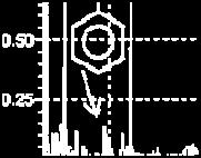


137 123 Figure 5-10: GC/MS chromatograms of dodecane: original sample (top); stressed at 450 o C for 2h (middle) and 4h (bottom)


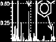


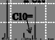

138 124 Figure 5-11: GC/MS chromatograms of Norpar-13: original sample (top); stressed at 450 o C for 2h (middle) and 4h (bottom)
139 NMR Analysis The samples after 4 h of stressing were also analyzed using NMR spectroscopy to see the changes in the liquid. Figure 5-12 and Figure 5-13 shows the 13 C and 1 H NMR spectra, respectively, of the neat samples along with the liquid stressed after 4 h. As mentioned earlier, the NMR analysis was done to confirm whether there were aromatic compounds present in the samples. For 13 C NMR, aliphatic carbons were expected at chemical shift between ppm, while alkenes and aromatic carbons were expected in the chemical shift region ppm 106. In the case of 1 H NMR, aliphatic hydrogen were expected at chemical shift between ppm, while aromatic hydrogen were expected in the chemical shift region ppm 107. The 13 C and 1 H NMR showed the presence of aromatics and alkenes after 4 h of stressing at 450 o C, thus agreeing with the results of GC/MS.
140 126 Aliphatic carbons Aromatic carbons + alkenes Deuterated chloroform Chemical Shift, ppm 0 (a) Aliphatic carbons Aromatic carbons +alkenes Chemical Shift, ppm 0 (b)
141 127 Aliphatic carbons Aromatic carbons +alkenes Chemical Shift, ppm 0 (c) Figure 5-12: 13 C NMR spectra of stressed samples at 450 o C for 4h of: (a) JP-900; (b) dodecane and (c) Norpar-13
142 128 Aliphatic hydrogen Aromatic hydrogen TMS Chemical Shift, ppm 2 0 (a) Aliphatic hydrogen Aromatic hydrogen Chemical Shift, ppm 2 0 (b)
143 129 Aliphatic hydrogen Aromatic hydrogen Chemical Shift, ppm 2 0 (c) Figure 5-13: 1 H NMR spectra of stressed samples at 450 o C for 4h of: (a) JP-900; (b) dodecane and (c) Norpar-13 In summary, the coal-based fuel JP-900, Norpar-13 and dodecane, when stressed at 200 o C for 4 h, did not show the presence of insoluble products and can be considered to be stable. For the pyrolytic regime JP-900 produced less gas than the paraffinic fuels. From GC/MS results the higher thermal stability of coal-based fuel under a N 2 atmosphere in comparison to the long-chain alkanes (C12-C15) can be attributed mainly to its higher content of cycloalkanes. The NMR spectroscopy confirmed the results from GC/MS for the absence of aromatics in the original samples and its presence in the samples stressed at 450 o C for 4 h.
144 Chapter 6 Summary, Conclusions and Suggestions for Future Work 6.1 Summary The aim this work was to mix a coal-based fuel JP-900 with two model paraffinic fuels, dodecane and Norpar-13, and investigate the impact of blending them on jet fuel properties. JP-900 was mixed with both dodecane and Norpar-13 and there were no unusual effects, such as precipitation, after the mixture was allowed to stand. The chemical compositions of the feedstocks and the blends were analyzed by GC/MS and NMR spectroscopy. The feedstock and the blends were tested for thermal oxidative and thermal pyrolytic stability for extended periods of time and some of the properties were tested to see if they meet the specification standard of current jet fuels. Finally selected properties were determined if there were synergistic or antagonistic effects between the two components of the blend. The coal-based fuel JP-900 was produced by hydrotreating and hydrogenating a blend of RCO (refined chemical oil), and LCO (light cycle oil) at 1:1 ratio by weight. It was produced at Intertek-PARC in Harmarville, PA. The JP-900 has been blended with paraffinic fuels such as dodecane and Norpar-13 and their thermal stabilities have been tested in the oxidative and pyrolytic regimes using a microautoclave, or tubing bomb. Properties, such as density, net heat of combustion, smoke point, flash point, viscosity and freezing point were also determined.
145 131 GC/MS analysis was conducted on the fresh coal-based jet fuel (JP-900), the two models paraffinic fuels and all the blends. The compositions of all jet fuels were reported quantitatively based on seven basic compound classes. The distinction between the coalbased fuel and the paraffinic fuel is mainly the amount of alkanes and cycloalkanes. The paraffinic fuels are composed of long-chain alkanes (C12-C15) while cyclic structures are abundant in JP-900 fuel. The results from the NMR analyses for the fresh samples did not show the presence of aromatics and in addition, the stressed liquid in the pyrolytic regime showed the presence of aromatics. GC/MS was very useful for me in comparison to NMR because it helped identify the compounds. The high content of cyclic compounds and low content of alkanes in JP-900 have made this fuel be outside the specifications of jet fuel for some properties such as density, API gravity and hydrogen content. These results are in good agreement with the findings of Balster et al. 16 Because of the high cycloalkanes content of the coal-based fuel, JP-900 is more dense than dodecane or Norpar-13. This high density of JP-900 is also the cause for the low API gravity. The net heat of combustion was at the borderline (42.9 MJ/kg) of the required net heat of combustion (42.8 MJ/kg). To remediate the situation concerning the density, API gravity and hydrogen content, the blending of the coal-based fuel, JP- 900 and the two models paraffinic fuels, Norpar-13 and dodecane improved the mixture JP-900/paraffinic fuel from 20/80 vol % to 70/30 vol % to meet the current specification. For the hydrogen content, adding dodecane or Norpar-13 to JP-900 did improve the entire blend and thus the net heat of combustion and smoke point were also ameliorated. Although the high content of cycloalkanes did not favor the density and hydrogen content, the presence of decalins and its derivatives was a positive factor for the JP-900
146 132 fuel, because it helped lower its freezing point in comparison to the long-chain alkanes. In the case of the freezing point, blending JP-900 with long-chain alkanes was out of specification because the freezing point of the paraffinic fuel was very high and thus responsible for increasing the freezing point of the blends. Jet engines need fuels that have low freezing point and sufficient viscosity to assure fuel flow and pumping capability at high altitude and high speed. Some properties of the blend such as density, distillation range, hydrogen content, and energy content were additive. But others had antagonistic effects such as the sulfur content, the flash point and kinematic viscosity, while only one blend, (90/10) JP-900/paraffinic fuel, showed a synergistic effect. Models from the literature were tested on the flash point, freezing point, viscosity and smoke point. The correlation proposed by Wickey and Chittenden 102 predicted the flash point of the JP-900/Norpar-13 blend with an average absolute error of 1.8 o C and 1.5 o C for the JP-900/dodecane mixture when comparing the predicted values versus the experimental values. The Moharam et al. 52 model accurately predicted the kinematic viscosity of the feedstock and all the blends with an average absolute error of 0.35 cst. Except for the coal-based fuel JP-900, the Cookson et al. 58 model accurately predicts the freeze point temperatures of the blends and the paraffinic fuels, with an average absolute error, predicted versus observed, of 1.95 o C for JP-900/Norpar-13 and 3.2ºC for the JP-900/dodecane blend. For the sooting tendency, the model from Cookson et al. 56 predicted accurately the smoke of the coal-based fuel and two blends B101 and B201 with an absolute error of 1mm.
147 133 The thermal stability of the coal-based fuel and the paraffinic fuels along with their blends was assessed using tubing bomb reactors. For the oxidative regime, the fuels were tested at 200 o C for 4 h and pressurized with air. There were no solid deposits present, and all the remaining fuel was above 90 wt %. In addition the GC/MS results of the stressed liquid showed no significant changes in the intensity of the peaks, but it did show the appearance of some minor products, such as alcohols and ketones, with concentration less than 1 wt %. Therefore JP-900, dodecane, Norpar-13 and all the blends were considered stable at the present conditions. In the case of pyrolytic stability, the testing was achieved at 450 o C for 2 and 4 h in a nitrogen atmosphere. This is an important study because the condition represents the period after landing of high-mach flight advanced jet aircraft, where some fuel is confined in very hot fuel lines for a certain period of time 78. Since no solids were present in stressed liquids, the gas formation was the only factor used to compare the stability of the fuel samples. The GC/MS spectra of the coal-based JP-900 at 2 h and 4 h did not show major differences in the peaks as in the case of the paraffinic fuels. After 2 h of stressing of the paraffinic fuels, the relative intensity of many peaks changed and this trend became more noticeable after 4 h of stressing. As the liquid was decreasing, the gas formation was increasing. The gas formation for JP-900 was 13 wt % while the gas for the paraffinic fuels were 35 wt % and 41 wt % for dodecane and Norpar-13 respectively when stressed for 4 h. From the GC/MS results, the higher thermal stability of coal-based fuel under a N 2 atmosphere can be attributed mainly to its higher content of cycloalkanes. Another important reason for no solid formation and less gas formation for long period of time from JP-900 is the presence of hydrogen donors such as decalin, which inhibit the chain reaction induced by
148 134 radicals from unstable compounds. The decomposition of JP-900 produced toluene, with other alkybenzenes and some hydroaromatics, such as indanes and tetralins. For the paraffinic fuels the decomposition of dodecane and Norpar-13 produced shorter compounds from C7 to C11 containing both alkanes and alkenes as shown by their GC/MS. They also produced compounds such as toluene and other alkylbenzenes. As mentioned earlier, JP-900 is thermally stable compared to dodecane and Norpar-13 because of less gas formation. And as expected the addition of paraffinic fuels to the coal-based fuel exhibited lower thermal stability than JP Conclusions The present study shows that a coal-based fuel can be successfully blended with two model paraffinic fuels, dodecane and Norpar-13, at any proportion without any unusual effects such as precipitations or phase separation. The difference between the chemical composition of the coal-based and paraffinic fuels was shown to be the concentration of cycloalkanes and alkanes. Futhermore, this work has several important implications to the development of future jet fuels. First, jet fuels produced by hydrotreating and hydrogenating a blend of refined chemical oil (RCO), and light cycle oil (LCO) are rich in cycloalkanes, especially decalins, which make them thermally stable at high temperature. Thus the high contents of cyclic compounds in jet fuels make them good candidate for high-performance engines because the fuel can act as heat sink for the cooling of lubricating oil and hydraulic fluid 12, 59. Second, the blending of paraffinic fuels with coal-based jet fuels may significantly
149 135 enhance their thermal stability. Finally, when blended JP-900 with dodecane or Norpar- 13, decalins play a role of hydrogen donor by suppressing or even eliminating the formation of carbonaceous deposits at 450 o C. In addition the blend of cycloalkanes and alkanes which are main components of JP-900 and Norpar-13 or dodecane respectively could be a good replacement of the highly thermally stable fuel JP-7 used in high-mach engine. Moreover, blending JP-900 with dodecane or Norpar-13 was advantageous because the presence of long-chain alkanes helped improved some of the properties of the current jet fuel specifications such as density, API gravity, hydrogen content and net heat of combustion. The blending of coal-based with paraffinic fuels could reduce the use of jet fuels derived from crude oil and therefore reduce the US dependency on foreign oil. However, the mixture of JP-900 and Norpar-13 or dodecane showed freezing point that were out of specification because the model paraffinic fuels, dodecane and Norpar-13, have higher freezing point and increase the overall freezing points of the blends. Finally, the JP-900/paraffinic fuels blends fit some predicting equations presented in the literature for the calculation of some properties such as the flash point, freezing point and kinematic viscosity. The implication of this is that JP-900 could be blended with conventional jet fuel or the synthetic jet fuel (e.g Fischer-Trospch liquids) with confidence. The JP-900 blend did not fit in the predicted equation of the smoke point proposed by Cookson et al. 56. Thus it would be important to look for others models to apply to the blends.
150 Suggestions for Future Work 1) For the thermal stability tests, it would be interesting to increase the temperature and residence time to see for how long the blends of JP-900/paraffinic fuels would stay stable with or without formation of solids. For example it would be expected that, for duration of 24 h solid deposits may be presents. Also the use of micro-filters will be a good tool to use to check for suspended solids in the stressed samples since the remaining liquid will be opaque and difficult to judge just by the naked eye. 2) The thermal stability of the blends achieved in the tubing bomb should be compared with the results from flow reactors or other reactors. Fuel stressed in flow reactors for example would have different results from the microautoclave reactor because of the conditions and also the coating of the reactor. 3) The coal-based JP-900 should be distilled and the jet fuel fraction ( o C) be used for mixture with paraffinic fuels, and study of the properties. From the simulated distillation of the coal-based fuel, it appeared that JP-900 was not 100% jet fuel. So using a fuel within the jet fuel fraction range would give better results that one can rely on. 4) The blends of JP-900/paraffinic fuel could be tested for combustion characteristics in a high pressure gas turbine combustor for analysis of NO x, CO 2, CO and O 2 emission. For environmental purposes it would useful to know the quantity and quality of emissions these blends will contribute, due to the fuel composition or thermal No x. The NO x emissions from the blends would be expected to be higher relative to the pure components.
151 137 5) The coal-based fuel JP-900 should be blended also with Fischer-Tropsch jet fuel to investigate the impact of the blending on jet fuel properties. Fisher-Tropsch fuels are already in use in South Africa as jet fuel, and since it is essentially a paraffinic fuel, the blend with JP-900 would help prevent the rapid decomposition of the fuel at temperature above 450 o C. JP-900 is rich in cycloalkanes and theses compounds are more stable compared to long-chain alkanes with the same carbon number 12. In addition the presence of hydrogen donors such as decalin will help inhibit the reaction induced by radicals from unstable compounds 12.
152 References 1. PennState Coal-Based Jet Fuel Poised for Next step. Science Daily. (Retrieved January 30, 2009 from 2. PennState Coal- based Alternative Jet Fuel did " A-O.K." in Test Burn. (Retrieved June 15, 2009 from 3. Butnark, S. Hydrogenation Of Coal Tar Fractions And Refinery Streams. M.S Thesis, The Pennsylvania State University, PA, Burgess, C. E. Direct Coal Liquefaction: A Potential Route to Thermally Stable Jet Fuel; The Pennsylvania State University: University Park, PA, Escallon, M. M. Reaction of Decant Oil and Bituminous Coal at 465 o C in a Laboratory Scale Coker. M.S Thesis, The Pennsylvania State University, PA, Fickinger, A. E. Laboratory-Scale Coking of Coal/Petroleum Mixtures. M.S. Thesis, The Pennsylvania State University, PA, Cookson, D. J., and Smith, B.E., Observed and Predicted Properties of Jet and Diesel Fuels Formulated from Coal Liquefaction and Fischer-Tropsch Feedstocks. Energy & Fuels 1992, 6, (5), Lamprecht, D., Fischer-Tropsch Fuel for Use by the US Military as Battlefield-Use Fuel of the Future. Energy & Fuels 2007, 21, (3), Solash, J., Hazlett, R.N., Hall, J.M. and Nowack, C. J., Relation between Fuel Properties and Chemical Composition. 1. Jet Fuels from Coal, Oil Shale and Tar Sands. Fuel 1978, 57, (9), EIA Coal Reserves Current and Back Issues. (Retrieved July 2009 from Edwards, T., Recent Research Results in Advanced Fuels. Preprints of Papers, American Chemical Society Division of Petroleum Chemistry 1996, 41, (2), Song, C., Eser, S., Schobert, H.H. and Hatcher, P.G., Pyrolytic Degradation Studies of a Coal-Derived and a Petroleum-Derived Aviation Jet Fuel. Energy & Fuels 1993, 7, (2), Edwards, T., and Zabarnick, S., Supercritical Fuel Deposition Mechanisms. Industrial and Engineering Chemistry Research 1993, 32, (12), Zabarnick, S., Studies of Jet Fuel Thermal Stability and Oxidation Using a Quartz Crystal Microbalance and Pressure Measurements. Industrial and Engineering Chemistry Research 1994, 33, (5), Yu, J., and Eser, S., Thermal Decomposition of C10-C14 Normal Alkanes in Near- Critical and Supercritical Regions: Product Distributions and Reaction Mechanisms. Industrial and Engineering Chemistry Research 1997, 36, (3), Balster, L. M., Corporan, E., DeWitt, M. J., Edwards, J. T., Ervin, J. S., Graham, J. L., Lee, S. Y., Pal, S., Phelps, D. K., Rudnick, L. R., Santoro, R. J., Schobert, H. H., Shafer, L. M.,; Striebich, R. C., West, Z. J., Wilson, G. R., Woodward, R., and Zabarnick, S., Development of an Advanced, Thermally Stable, Coal-Based Jet Fuel. Fuel Processing Technology 2008, 89, (4),
153 17. Butnark, S. Thermally Stable Coal-Based Jet Fuel: Chemical Composition, Thermal Stability, Physical Properties and their Relationships. Ph.D Dissertation, The Pennsylvania State University, PA, Andresen, J. M., Strohm, J. J., Sun, L. and Song, C., Relationship between the Formation of Aromatic Compounds and Solid Deposition during Thermal Degradation of Jet Fuels in the Pyrolytic Regime. Energy & Fuels 2001, 15, (3), Berkhous, S. K. Low Temperature Oxidation of Jet Fuel: Effect of Oxygenated Compounds on Freeze Point. M.S Thesis, The Pennsylvania State University, PA, Coleman, M. M.; Selvaraj, L.; Sobkowiak, M. Toward the Design of Thermally Stable Jet Fuels at Both Moderate (250 o C) and High (>400 o C); The Pennsylvania State University: University Park, Pa, OCtober-December Sobkowiak, M., Burgess, C. E. and Beaver, B., High Heat Sink Jet Fuels. 2. Stabilization of a JP-8 with Model Refined Chemical Oil/Light Cycle Oil (RCO/LCO)-Derived Stabilizers. Energy & Fuels 2007, 21, (2), Song, C., Lai, W. C. and Schobert, H. H., Hydrogen-Transferring Pyrolysis of Cyclic and Straight-Chain Hydrocarbons. Enhancing High Temperature Thermal Stability of Aviation Jet Fuels by H-Donors. Preprints of Papers, American Chemical Society Division of Fuel Chemistry 1992, 37, (4), Yang, Y., Boehman, A.L. and Santoro, R.J., A Study of Jet Fuel Sooting Tendency using the Threshold Sooting Index (TSI) Model. Combustion and Flame 2007, 149, (1-2), Maurice, L. Q., Lander, H., Edwards, T. and Harrison, W. E., Advanced Aviation Fuels: A Look Ahead Via a Historical Perspective. Fuel 2001, 80, (5), ASTM D 1655 Standard Specification for Aviation Turbine Fuels; ASTM International: Chevron Aviation Fuels Technical Review; CRC Handbook of Aviation Fuel Properties; Report No. 635; Alpharetta, GA, Edwards, T., Liquid Fuels and Propellants for Aerospace Propulsion. Journal of Propulsion and Power 2003, 19, (6), Edwards, T., Harrison, W.E. and Maurice, L.Q. In Properties and Usage of Air Force Fuel: JP-8, 39 th AIAA Aerospace Sciences Meeting & Exhibit, Reno, NV, 2001; Reno, NV, NASA Dryden Flight Research Center Photo Collection. (Retrieved June, 2009 from Wikipedia Lockheed U-2. (Retrieved June, 2009 from CRC Handbook of Aviation Fuels Properties; Report No 530; Atlanta, GA, Strauss, K. H., Aviation Fuels. In Significance of Tests for Petroleum Products (7th Edition): (MNL 1), Rand, S. J., Ed. ASTM International: 2003; p Speight, J. G., Handbook of Petroleum Product Analysis. John Wiley & Sons: 2002; p Riazi, M. R., Characterization and Properties of Petroleum Fractions. ASTM International, West Conshohoken, PA: 2005; p Mushrush, G. W., and Speight, J.G, Petroleum Products: Instability and Incompatibility. Taylor & Francis: 1995; p ASTM D 1298 Standard Test Method for Density, Relative Density (Specific Gravity), or API Gravity of Crude Petroleum and Liquid Petroleum Products by Hydrometer Method; ASTM International: ASTM D 4052 Standard Test Method for Density and Relative Density of Liquids by Digital Densitymeter; ASTM International:
154 39. ExxonMobil World Jet Fuel Specifications with Avgas Supplement; ASTM D 86 Standard Test Method for Distillation of Petroleum Products at Atmospheric Pressure; ASTM International: ASTM D 2887 Standard Test Method for Boiling Range Distribution of Petroleum Fractions by Gas Chromatography; ASTM International: Daubert, T. E., and Danner, R. P., In API Technical Data Book-Petroleum Refining, 6th ed, Washington, DC, 1997; Vol ASTM D 93 Standard Test Methods for Flash Point by Pensky-Martens Closed Cup Tester; ASTM International: Riazi, M. R., and Daubert, T. E., Predicting Flash and Pour Points. Hydrocarbon Process 1987, 66, (9), ASTM D 3828 Standard Test Methods for Flash Point by Small Scale Closed Cup Tester; ASTM International: ASTM D 56 Standard Test Method for Flash Point by Tag Closed Cup Tester; ASTM International: ASTM D 6450 Standard Test Method for Flash Point by Continuously Closed Cup (CCCFP) Tester; ASTM International: Longwell, J. P., Interface Between Fuels and Combustion. In Fossil Fuel Combustion: A source Book, Bartok, W.; Sarofim, A. F., Eds. Wiley -Interscience: 1991; pp Reid, R. C., Prausnitz, J.M. and Poling, B.E., The Properties of Gases and Liquids. Mc Graw-Hill Book Compagny: 1987; p Daubert, T. E., and Danner, R. P., In API Technical Data Book-Petroleum Refining, 4th ed., Washinton, DC, 1984; Vol ASTM D 445 Standard Test Method for Kinematic Viscosity of Transparent and Opaque Liquids (and Calculation of Dynamic Viscosity); ASTM International: Moharam, H. M., Al-Mehaideb, R. A. and Fahim, M. A., New Correlation for Predicting the Viscosity of Heavy Petroleum Fractions. Fuel 1995, 74, (12), ASTM D 7153 Standard Test Method for Freezing Point of Aviation Fuels (Automatic Laser Method); ASTM International: ASTM D 2386 Standard Test Method for Freezing Point of Aviation Fuels; ASTM International: ASTM D 5972 Standard Test for Freezing Point of Aviation Fuels ( Automatic Phase Transition Method); ASTM International: Cookson, D. J., Iliopoulos, P. and Smith, B.E., Composition-Property Relations for Jet and Diesel Fuels of Variable Boiling Range. Fuel 1995, 74, (1), Cookson, D. J., Latten, J.L., Shaw, I.M. and Smith, B.E., Property-Composition Relationships for Diesel and Kerosene Fuels. Fuel 1985, 64, (4), Cookson, D. J., Lloyd, C.P. and Smith, B.E., Investigation of the Chemical Basis of Kerosene (Jet Fuel) Specification Properties. Energy & Fuels 1987, 1, (5), Vere, R. A., Aviation Fuels. In Modern Petroleum Technology, 4 th ed.; Hobson, G. D., Ed. John Wiley & Sons: 1973; pp Goodger, E., and Vere, R., Aviation Fuels Technology. MacMillian publishers Ldt: 1985; p ASTM D 1322 Standard Test Method for Smoke Point of Kerosine and Aviation Turbine Fuel; ASTM International: The Institute of Petroleum., Modern Petroleum Technology. 3rd ed.; The Institute of Petroleum: 1962; p Albahri, T. A., Riazi, M. R. and Alqattan, A. A., Analysis of Quality of the Petroleum Fuels. Energy & Fuels 2003, 17, (3),
155 64. ASTM D 4809 Standard Test Method for Heat of Combustion of Liquid Hydrocarbon Fuels by Bomb Calorimeter; ASTM International: Atria, J. and Edwards, J. T. High Temperature Cracking and Deposition Behavior of an n-alkane Mixture; The Pennsylvania State University: University Park, PA, October December Bredael, P., and Rietvelde, D., Pyrolysis of Hydronapthalenes. 2. Pyrolysis of Cis- Decalin. Fuel 1979, 58, (3), Bredael, P., and Vinh, T.H., Pyrolysis of Hydronaphthalenes. 1. Pyrolysis of Tetralin, 1,2-Dihydronaphthalene and 2-Methylindene. Fuel 1979, 58, (3), Lai, W. C., and Song, C., Pyrolysis of Alkylcyclohexanes in or Near the Supercritical Phase. Product Distribution and Reaction Pathways. Fuel Processing Technology 1996, 48, (1), Voge, H. H., and Good, G. M., Thermal Cracking of Higher Paraffins. The Journal of American Chemical Society 1949, 71, (2), Yu, J., and Eser, S., Thermal Decomposition of Jet Fuel Model Compounds under Near- Critical and Supercritical Conditions. 1. n-butylbenzene and n-butylcyclohexane. Industrial and Engineering Chemistry Research 1998, 37, (12), Yu, J., and Eser, S., Thermal Decomposition of Jet Fuel Model Compounds under Near- Critical and Supercritical Conditions. 2. Decalin and Tetralin. Industrial and Engineering Chemistry Research 1998, 37, (12), Zhou, P., and Crynes, B.L., Thermolytic Reactions of Dodecane. Industrial and Engineering Chemistry Process Design and Development 1986, 25, (2), Zabarnick, S., Chemical Kinetic Modeling of Jet Fuel Autoxidation and Antioxidant Chemistry. Industrial and Engineering Chemistry Research 1993, 32, (6), Heneghan, S. P., and Zabarnick, S., Oxidation of Jet Fuels and the Formation of Deposit. Fuel 1994, 73, (1), CRC., Handbook of Aviation Fuel Properties, CRC Report No. 635; Alpharetta, GA, Jones, E. G., and Balster, L. M., Interaction of a Synthetic Hindered-Phenol with a Natural Fuel Antioxidant in the Autoxidation of Paraffins. Energy & Fuels 2000, 14, Beaver, B. D., Gao, L., Fedak, M.G., Coleman, M. M. and Sobkowiak, M., Model Studies Examining the Use of Dicyclohexylphenylphosphine to Enhance the Oxidative and Thermal Stability of Future Jet Fuels. Energy & Fuels 2002, 16, (5), Song, C., Lai, W.C. and Schobert, H. H., Condensed-Phase Pyrolysis of n-tetradecane at Elevated Pressures for Long Duration.Product Distribution and Reaction Mechanisms. Industrial and Engineering Chemistry Research 1994, 33, (3), Yu, J., and Eser, S., Kinetics of Supercritical-Phase Thermal Decomposition of C10-C14 Normal Alkanes and Their Mixtures. Industrial and Engineering Chemistry Research 1997, 36, (3), Song, C., Peng, Y., Jiang, H. and Schobert, H. H., On the Mechanisms of PAH and Solid Formation during Thermal Degradation of Jet fuels. Preprints of Papers, American Chemical Society Division of Petroleum Chemistry 1992, 37, p Kossiakoff, A., and Rice, F.O., Thermal Decomposition of Hydrocarbons, Resonance Stabilization and Isomerization of Free Radicals. Journal of the American Chemical Society 1943, 65, (4), Rice, F. O., The Thermal Decomposition of Organic Compounds from the Standpoint of Free Radicals. III. The Calculation of the Products Formed from Paraffin Hydrocarbons. The Journal of American Chemical Society 1933, 55, (7),
156 83. Fabuss, B. M., Smith, J. O., Lait, R. I., Borsanyi, A. S. and Satterfield, C. N., Rapid Thermal Cracking of n-hexadecane at Elevated Pressures. Industrial and Engineering Chemistry Process Design and Development 1962, 1, (4), Zhou, P., Hollis, O. L. and Crynes, B.L., Thermolysis of Higher Molecular Weight Straight-Chain Alkanes (C9-C22). Industrial and Engineering Chemistry Research 1987, 26, (4), Hillebrand, W., Hodek, W. and Kölling, G., Steam Cracking of Coal-Derived Oils and Model Compounds : 1. Cracking of Tetralin and t-decalin. Fuel 1984, 63, (6), Hooper, R. J., Battaerd, H. A. J. and Evans, D.G., Thermal Dissociation of Tetralin Between 300 and 450 C. Fuel 1979, 58, (2), Song, C., Lai, W.C. and Schobert, H.H., Hydrogen-Transferring Pyrolysis of Long-Chain Alkanes and Thermal Stability Improvement of Jet Fuels by Hydrogen Donors. Industrial & Engineering Chemistry Research 1994, 33, (3), Song, C.; Lai, W. C.; Schobert, H. H., Hydrogen-Transferring Pyrolysis of Long-Chain Alkanes and Thermal Stability Improvement of Jet Fuels by Hydrogen Donors. Ind. Eng. Chem. Res. 1994, 33, (3), Poutsma, M. L., Free-Radical Thermolysis and Hydrogenolysis of Model Hydrocarbons Relevant to Processing of Coal. Energy & Fuels 1990, 4, (2), Daubert, T. E., and Danner, R. P., Physical and Thermodynamic Properties of Pure Chemicals. In Design Institute for Physical Property Data, AIChE, Washingon, DC, Dasgupta, R., and Maiti, B.R., Thermal Dehydrocondensation of Benzene to Diphenyl in a Nonisothermal Flow Reactor. Industrial and Engineering Chemistry Process Design and Development 1986, 25, (2), Peng, Y., Schobert, H. H., Song, C. and Hatcher, P. G., Effects of the Structure of the Side Chain on the Pyrolysis of Alkylbenzenes. Preprints of Papers, American Chemical Society Division of Fuel Chemistry 1992, 37, (4), Schobert, H. H., Badger, M. W. and Santoro, R. J., Progress Toward Coal-Based JP-900. Preprints of Papers, American Chemical Society Division of Petroleum Chemistry 2002, 47, (3), Khorasheh, F., and Gray, M.R., High-Pressure Thermal Cracking of n-hexadecane in Tetralin. Energy & Fuels 1993, 7, (6), Song, C., Nihonmatsu, T., and Nomura, M., Effect of Pore Structure of Nickelmolybdenum/alumina Catalysts in Hydrocracking of Coal-Derived and Oil Sand Derived Asphaltenes. Industrial & Engineering Chemistry Research 1991, 30, (8), Schobert, H. H. Advanced Thermally Stable Coal-Based Jet Fuels; The Pennsylvania State University: University park, PA, Song, C., Eser, S., Schobert, H.H and Hatcher, P. G., Thermal Stability of Petroleum and Coal-Derived Jet Fuels at High Temperatures Preprints of Papers, American Chemical Society Division of Petroleum Chemistry 1992, 37, (1-2), Banes, J. S.; Wilson, G. R.; Absil, R. P. L. Refinery Integration Project; PARC Technical Services Inc.: ASTM D 1552 Standard Test Method for Sulfur in Petroleum Products (High- Temperature Method); ASTM International: ASTM D 3241 Standard Test Method for Thermal Oxidation Stability of Aviation Turbine Fuels ASTM International: Roquemore, W. M., Pearce, J.A., Harisson III, W.E., Krazinski, J.L. and Vanka, S.P., Fouling in Jet Fuel : A New Approach. Preprints of Papers, American Chemical Society Division of Petroleum Chemistry 1989, 34, (4),
157 102. Wickey, R. O., and Chittenden, D. H., Flash Point of Blends Correlated. Hydrocarbon Processing 1963, 42, (6), CRC Handbook of Chemistry and Physics, 89 th Ed; Boca Raton, Florida, A.P.I, In API Technical Data book - Petroleum Refining, 6th ed, American Petroleum of Institute: Washington DC, Zabarnick, S., and Widmor, N., Studies of Jet Fuel Freezing by Differential Scanning Calorimetry. Energy & Fuels 2001, 15, King, S. B. Typical Chemical Shifts in Carbon NMR Spectra. (Retrieved August 2009, from King, S. B. Typical chemical Shifts in Proton NMR Spectra. (Retrieved August, 2009 from Hites, R. A., Gas Chromatography Mass Spectroscopy. In Handbook of Instrumental Techniques for Analytical Chemistry, Settle, F. A., Ed. Prentice Hall PTR: 1997; pp Villalanti, D. C., Raia, J. C and Maynard, J. B, High-Temperature Simulated Distillation Applications in Petroleum Characterization. In Encyclopedia of Analytical Chemistry, Meyers, R. A., Ed. John Wiley & Sons Ltd: Chichester, 2000; pp Daubert, T. E., Petroleum Fraction Distillation Interconversion. Hydrocarbon Processing 1994, 73, (9), Riazi, M. R., and Daubert, T.E., Analytical Correlations Interconvert Distillation Curves Types. Oil & Gas Journal 1986, 84, Berkhous, S. K. Thermal Oxidative Stability of Coal-Based JP-900 Jet Fuel: Impact on Selected Physical Properties. Ph.D Dissertation, The Pennsylvania State University, PA, Balster, L. M., Balster, W. J and Jones, E. G., Thermal Stability of Jet-fuel/Paraffin Blends. Energy & Fuels 1996, 10, Jones, E. G., Balster, L. M. and Balster, W. J., Thermal Stability of Jet-A Fuel Blends. Energy & Fuels 1996, 10, (2), Roan, M. A., and Boehman, A. L., The Effect of Fuel Composition and Dissolved Oxygen on Deposit Formation from Potential JP-900 Basestocks. Energy & Fuels 2004, 18, (3), Lai, W. C., Song, C., Schobert, H.H. and Arumugam, R., Pyrolytic Degradation of Coal and Petroleum-Derived Aviation Jet Fuels and Middle Distillates. Preprints of Papers, American Chemical Society Division of Fuel Chemistry 1992, 37, (4),
158 144 Appendix A Model Calculations of Selected Properties A-1 Model Calculation of the Flash Point The API standard method( given below in equation A-1) for the estimation of the flash point of petroleum fractions was used to predict the flash point of JP-900, dodecane and Norpar A-1 T 10 is the temperature at which 10 % of the fuel has vaporized under ASTM D 86 and it is in kelvins. T 10 was converted from simulated distillation to ASTM D86 using equation A-2: %.. A %. 50 %. Example of calculation for the JP-900 flash point 10 % %
159 For the blends, the flash points were determined using the flash point indexes of the components as given below in equation A A-3 where BI F is the flash point blending index of the component and T F the flash point in Kelvin. The blending index for the flash point of the final blend was evaluated using the following relation A-4 Σ A-4 where x vi is the volume fraction and BI i the blending index of component i. Equation A-5 was derived from A-3 for the predictions of the flash of the blends A-5 Example of calculation of the B101 flash point:
160 B101 is the mixture of 90 % of JP-900 and 10 % of Norpar K A-2 Model Calculation of the Kinematic Viscosity Moharam et al. 52 have developed an empirical correlation to predict the kinematic viscosity of petroleum fractions using mid-boiling point temperature T b, the absolute temperature T and specific gravity γ as input parameters that has the following form (A- 6): (A-6) where , γ is the specific gravity, T b and T are expressed in kelvins
161 147 is the kinematic viscosity of the fraction in mm 2 /s or cst Example calculation of kinematic viscosity of the coal based fuel JP A-3 Model Calculation of the Freezing Point One model proposed by Cookson et al 58 for the freezing point prediction was used for the prediction of freezing point of the samples. The proposed model contains only one input, the weight fraction of n-alkanes. The predicted value was calculated using the following equation: (A-7) Example calculation of the freezing point of B %
162 A-4 Model Calculation of Smoke Point The smoke point was evaluated using the Cookson et al 56 model. The model proposed contains three inputs, the weight fraction of n-alkanes and aromatics and also the temperatures of liquid distilled at 10 % and 90 %. The predicted value was calculated using equation A-8: (A-8) Example calculation of B103 smoke point %

; stressed at 450 o C for 2h (middle) and")
163 149 Appendix B GC/MS Chromatograms of the Original and Stressed Blends Figure B- 1: GC/ /MS chromatograms of B101: original sample (top); stressed at 450 o C for 2h (middle) and 4h (bottom)


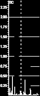


164 150 Figure B- 2: GC/ /MS chromatograms of B103: original sample (top); stressed at 450 o C for 2h (middle) and 4h (bottom)

;")
 and")
165 151 Figure B- 3: GC/ /MS chromatograms of B105: original sample (top); stressed at 450 o C at 2h (middle) and 4h (bottom)
166 152 Figure B- 4: GC/ /MS chromatograms of B107: original sample (top); stressed at 450 o C for 2h (middle) and for 4h (bottom)


167 153 Figure B- 5: GC/ /MS chromatograms of B109: original sample (top); stressed at 450 o C for 2h (middle) and for 4h (bottom)


; stressed")
 and")
168 154 Figure B- 6: GC/ /MS chromatograms of B201: original sample (top); stressed at 450 o C for 2h (middle) and 4h (bottom)


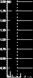


169 155 Figure B- 7: GC/ /MS chromatograms of B203: original sample (top); stressed at 450 o C for 2h (middle) and 4h (bottom)


170 156 Figure B- 8: GC/ /MS chromatograms of B205: original sample (top); stressed at 450 o C for 2h (middle) and 4h (bottom)


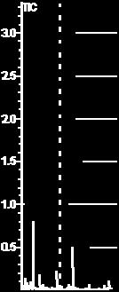


171 157 Figure B- 9: GC/ /MS chromatograms of B207: original sample (top); stressed at 450 o C for 2h (middle) and 4h (bottom)

;")
 and")
172 158 Figure B- 10: GC/MS chromatograms of B209: original sample (top); stressed at 450 o C for 2h (middle) and 4h (bottom)
Journal of KONES Powertrain and Transport, Vol. 21, No ISSN: e-issn: ICID: DOI: /
 Journal of KONES Powertrain and Transport, Vol. 1, No. 1 ISSN: 131- e-issn: 3-133 ICID: 1131 DOI: 1./131.1131 JET FUELS DIVERSITY Air Force Institute of Technology Ksiecia Boleslawa Street, 1-9 Warsaw,
Fischer-Tropsch Refining
 Fischer-Tropsch Refining by Arno de Klerk A thesis submitted in partial fulfillment of the requirements for the degree Philosophiae Doctor (Chemical Engineering) in the Department of Chemical Engineering
How we invented jet fuel without knowing what we were doing
 How we invented jet fuel without knowing what we were doing Harold Schobert Professor of Fuel Science Penn State University Nottingham University, May 2011 Frank Whittle The Father of Jet Propulsion The
On-Line Process Analyzers: Potential Uses and Applications
 On-Line Process Analyzers: Potential Uses and Applications INTRODUCTION The purpose of this report is to provide ideas for application of Precision Scientific process analyzers in petroleum refineries.
Module8:Engine Fuels and Their Effects on Emissions Lecture 36:Hydrocarbon Fuels and Quality Requirements FUELS AND EFFECTS ON ENGINE EMISSIONS
 FUELS AND EFFECTS ON ENGINE EMISSIONS The Lecture Contains: Transport Fuels and Quality Requirements Fuel Hydrocarbons and Other Components Paraffins Cycloparaffins Olefins Aromatics Alcohols and Ethers
PETE 203: Properties of oil
 PETE 203: Properties of oil Prepared by: Mr. Brosk Frya Ali Koya University, Faculty of Engineering, Petroleum Engineering Department 2013 2014 Lecture no. (3): Classification of Crude oil 6. Classification
The Pennsylvania State University. The Graduate School. Department or Graduate Program PHYSICAL PROPERTIES AND THEIR RELATIONSHIPS.
 The Pennsylvania State University The Graduate School Department or Graduate Program THERMALLY STABLE COAL-BASED JET FUEL: CHEMICAL COMPOSITION, THERMAL STABILITY, PHYSICAL PROPERTIES AND THEIR RELATIONSHIPS
Prediction of Physical Properties and Cetane Number of Diesel Fuels and the Effect of Aromatic Hydrocarbons on These Entities
 [Regular Paper] Prediction of Physical Properties and Cetane Number of Diesel Fuels and the Effect of Aromatic Hydrocarbons on These Entities (Received March 13, 1995) The gross heat of combustion and
Edexcel GCSE Chemistry. Topic 8: Fuels and Earth science. Fuels. Notes.
 Edexcel GCSE Chemistry Topic 8: Fuels and Earth science Fuels Notes 8.1 Recall that Hydrocarbons are compounds that contain carbon and hydrogen only 8.2 Describe crude oil as: A complex mixture of hydrocarbons
Distillation process of Crude oil
 Distillation process of Crude oil Abdullah Al Ashraf; Abdullah Al Aftab 2012 Crude oil is a fossil fuel, it was made naturally from decaying plants and animals living in ancient seas millions of years
Article: The Formation & Testing of Sludge in Bunker Fuels By Dr Sunil Kumar Laboratory Manager VPS Fujairah 15th January 2018
 Article: The Formation & Testing of Sludge in Bunker Fuels By Dr Sunil Kumar Laboratory Manager VPS Fujairah 15th January 2018 Introduction Sludge formation in bunker fuel is the source of major operational
Types of Oil and their Properties
 CHAPTER 3 Types of Oil and their Properties Oil is a general term that describes a wide variety of natural substances of plant, animal, or mineral origin, as well as a range of synthetic compounds. The
Petroleum Refining Fourth Year Dr.Aysar T. Jarullah
 Oil Products 1- Gaseous Fuels. Natural gas, which is predominantly methane, occurs in underground reservoirs separately or in association with crude oil. The principal types of gaseous fuels are oil (distillation)
Characterization of crude:
 Crude Oil Properties Characterization of crude: Crude of petroleum is very complex except for the lowboiling components, no attempt is made by the refiner to analyze for the pure components that contained
Experimental Investigations on a Four Stoke Diesel Engine Operated by Jatropha Bio Diesel and its Blends with Diesel
 International Journal of Manufacturing and Mechanical Engineering Volume 1, Number 1 (2015), pp. 25-31 International Research Publication House http://www.irphouse.com Experimental Investigations on a
Fuel Related Definitions
 Fuel Related Definitions ASH The solid residue left when combustible material is thoroughly burned or is oxidized by chemical means. The ash content of a fuel is the non combustible residue found in the
White Paper.
 The Advantage of Real Atmospheric Distillation Complying with the ASTM D7345 Test Method in the Distillation Process Introduction / Background In the past, refiners enjoyed a constant supply of the same
REBCO (RUSSIAN EXPORT BLEND CRUDE OIL) SPECIFICATION GOST
 SPECIFICATION GOST") REBCO (RUSSIAN EXPORT BLEND CRUDE OIL) SPECIFICATION GOST 51858-2002 Characteristics Units Result Test Method Density (Specific Gravity) @ 20 C g /sm 3 0.870 ASTM D5002 Sulphur Content wt.% 1.8 ASTM D4294
REBCO (RUSSIAN EXPORT BLEND CRUDE OIL) SPECIFICATION GOST 51858-2002 Characteristics Units Result Test Method Density (Specific Gravity) @ 20 C g /sm 3 0.870 ASTM D5002 Sulphur Content wt.% 1.8 ASTM D4294
Production of Biodiesel from Used Groundnut Oil from Bosso Market, Minna, Niger State, Nigeria
 Production of Biodiesel from Used Groundnut Oil from Bosso Market, Minna, Niger State, Nigeria Alabadan B.A. Department of Agricultural and Bioresources Engineering, Federal University, Oye Ekiti. Ajayi
Results Certified by Core Labs for Conoco Canada Ltd. Executive summary. Introduction
 THE REPORT BELOW WAS GENERATED WITH FEEDSTOCK AND PRODUCT SAMPLES TAKEN BY CONOCO CANADA LTD, WHO USED CORE LABORATORIES, ONE OF THE LARGEST SERVICE PROVIDERS OF CORE AND FLUID ANALYSIS IN THE PETROLEUM
Petroleum Refining Fourth Year Dr.Aysar T. Jarullah
 Catalytic Reforming Catalytic reforming is the process of transforming C 7 C 10 hydrocarbons with low octane numbers to aromatics and iso-paraffins which have high octane numbers. It is a highly endothermic
The Coal-Based Jet Fuel Program
 The Coal-Based Jet Fuel Program Harold Schobert Director, The Energy Institute September 1, 2005 Prehistory of JP-900 program In the 1980s, the Air Force had a program to make a replacement JP-8 from the
CHAPTER 2 REFINERY FEED STREAMS: STREAMS FROM THE ATMOSPHERIC AND VACUUM TOWERS
 CHAPTER 2 REFINERY FEED STREAMS: STREAMS FROM THE ATMOSPHERIC AND VACUUM TOWERS About This Chapter The previous chapter introduced crude oil as a mixture of compounds. The characteristics of these compounds
Oil & Gas. From exploration to distribution. Week 3 V19 Refining Processes (Part 1) Jean-Luc Monsavoir. W3V19 - Refining Processes1 p.
 Jean-Luc Monsavoir. W3V19 - Refining Processes1 p.") Oil & Gas From exploration to distribution Week 3 V19 Refining Processes (Part 1) Jean-Luc Monsavoir W3V19 - Refining Processes1 p. 1 Crude Oil Origins and Composition The objective of refining, petrochemical
Oil & Gas From exploration to distribution Week 3 V19 Refining Processes (Part 1) Jean-Luc Monsavoir W3V19 - Refining Processes1 p. 1 Crude Oil Origins and Composition The objective of refining, petrochemical
Fig:1.1[15] Fig.1.2 Distribution of world energy resources. (From World Energy Outlook 2005, International Energy Agency.)[16,17]
![Fig:1.1[15] Fig.1.2 Distribution of world energy resources. (From World Energy Outlook 2005, International Energy Agency.)[16,17]](/thumbs/89/100738047.jpg "Fig:1.1[15] Fig.1.2 Distribution of world energy resources. (From World Energy Outlook 2005, International Energy Agency.)[16,17]") Introduction :Composition of petroleum,laboratory tests,refinery feedstocks and products Fig:1.1[15] Fig.1.2 Distribution of world energy resources. (From World Energy Outlook 2005, International Energy
Introduction :Composition of petroleum,laboratory tests,refinery feedstocks and products Fig:1.1[15] Fig.1.2 Distribution of world energy resources. (From World Energy Outlook 2005, International Energy
This presentation focuses on Biodiesel, scientifically called FAME (Fatty Acid Methyl Ester); a fuel different in either perspective.
; a fuel different in either perspective.") Today, we know a huge variety of so-called alternative fuels which are usually regarded as biofuels, even though this is not always true. Alternative fuels can replace fossil fuels in existing combustion
Today, we know a huge variety of so-called alternative fuels which are usually regarded as biofuels, even though this is not always true. Alternative fuels can replace fossil fuels in existing combustion
3.2 The alkanes. Isomerism: Alkanes with 4 or more carbons show a type of structural isomerism called chain isomerism
 3.2 The alkanes Prior knowledge: Types of formula general, empirical, molecular, structural, displayed and skeletal. Nomenclature Structural isomers chain and position isomers Free radicals Aliphatic Alkanes
Paragon Scientific Ltd Proficiency Testing Scheme Schedule
 Paragon Scientific Ltd Proficiency Testing Scheme Schedule Proficiency Testing Scheme Schedule Page 1 of 16 Issue : 29/01/2015 Print : 25/06/2018 Viscosity ASTM D445 - Standard Test Method for Kinematic
Jet fuel control: Specification test methodology
 Jet fuel control: Specification test methodology 2 Contents appreciation of test methodology Recap specification requirements Key attributes of test methods Overview of test types Precision, accuracy,
Standard Test Method for Sulfur in the Analysis Sample of Coal and Coke Using High-Temperature Tube Furnace Combustion
 IAS Accreditation Number Company Name Address Contact Name Telephone +966-14-398-2118 Effective Date of Scope May 1, 2018 Accreditation Standard ISO/IEC 17025:2017 TL-743 Yanbu Industrial Area Yanbu, Madina
Study of viscosity - temperature characteristics of rapeseed oil biodiesel and its blends
 Study of viscosity - temperature characteristics of rapeseed oil biodiesel and its blends Li Kong 1, Xiu Chen 1, a, Xiaoling Chen 1, Lei Zhong 1, Yongbin Lai 2 and Guang Wu 2 1 School of Chemical Engineering,
Confirmation of paper submission
 Dr. Marina Braun-Unkhoff Institute of Combustion Technology DLR - German Aerospace Centre Pfaffenwaldring 30-40 70569 Stuttgart 28. Mai 14 Confirmation of paper submission Name: Email: Co-author: 2nd co-author:
Coking and Thermal Process, Delayed Coking
 Coking and Thermal Process, Delayed Coking Fig:4.1 Simplified Refinery Flow Diagram [1,2] Treatment processes : To prepare hydrocarbon streams for additional processing and to prepare finished products.
Conversion of Carinata Oil into Drop-in Fuels & Chemicals. Carinata Summit Quincy, Florida 15 March 2016
 Conversion of Carinata Oil into Drop-in Fuels & Chemicals Carinata Summit Quincy, Florida 15 March 2016 SOLVING PROBLEMS OF GLOBAL IMPORTANCE About ARA, Inc. Founded 1979, Albuquerque, New Mexico 1,086
Stray Gassing of Transformer. Streams and Addi;ves. Ed Casserly, Ph.D. Director - Refinery R&D Ergon Refining, Inc.
 Stray Gassing of Transformer Oils Effects of Refinery Streams and Addi;ves Ed Casserly, Ph.D. Director - Refinery R&D Ergon Refining, Inc. Presented at My Transfo 2014 Outline! Definition and Issue of Stray
Chapter 2 Outline: Alkanes
 Chapter 2 Outline: Alkanes 1. Structure of Alkanes & Cycloalkanes 2. Nomenclature overview 3. Newman Projections - Conformations of Alkanes in 3-D space 4. Chair Conformations - Conformations of Cycloalkanes
Zürich Testing on Fuel Effects and Future Work Programme
 Zürich Testing on Fuel Effects and 2016-2017 Future Work Programme Benjamin Brem 1,2, Lukas Durdina 1,2 and Jing Wang 1,2 1 Empa 2 ETH Zürich FORUM on Aviation and Emissions Workshop Amsterdam 15.04.2016
Biodiesel Product Quality Challenges: Gaylord Palm Resort and Convention Center, Orlando Florida, February 4, Fuel Quality Services, Inc.
 Biodiesel Product Quality Challenges: Gaylord Palm Resort and Convention Center, Orlando Florida, February 4, 2008 Overview Introduction Product Quality Challenges Manufacturing Storage Conclusion. Biodiesel
Chapter 4 ANALYTICAL WORK: COMBUSTION MODELING
 a 4.3.4 Effect of various parameters on combustion in IC engines: Compression ratio: A higher compression ratio increases the pressure and temperature of the working mixture which reduce the initial preparation
Hydrocarbons 1 of 29 Boardworks Ltd 2016
 Hydrocarbons 1 of 29 Boardworks Ltd 2016 Hydrocarbons 2 of 29 Boardworks Ltd 2016 What are hydrocarbons? 3 of 29 Boardworks Ltd 2016 Some compounds only contain the elements carbon and hydrogen. They are
CONTENTS 1 INTRODUCTION SUMMARY 2-1 TECHNICAL ASPECTS 2-1 ECONOMIC ASPECTS 2-2
 CONTENTS GLOSSARY xxiii 1 INTRODUCTION 1-1 2 SUMMARY 2-1 TECHNICAL ASPECTS 2-1 ECONOMIC ASPECTS 2-2 3 INDUSTRY STATUS 3-1 TRENDS IN TRANSPORTATION FUEL DEMAND 3-3 TRENDS IN ENVIRONMENTAL REGULATION 3-3
Gaseous fuel, production of H 2. Diesel fuel, furnace fuel, cracking
 ALKANES Introduction Hydrocarbons, as the name implies are compounds whose molecules contain only carbon and hydrogen. They are extracted from petroleum, natural gas and coal. Straight chain alkanes take
PRACTICE EXAMINATION QUESTIONS FOR 1.6 ALKANES (includes some questions from 1.5 Introduction to Organic Chemistry)
") PRACTICE EXAMINATION QUESTIONS FOR 1.6 ALKANES (includes some questions from 1.5 Introduction to Organic Chemistry) 1. (a) Name the process used to separate petroleum into fractions....... Give the molecular
PRACTICE EXAMINATION QUESTIONS FOR 1.6 ALKANES (includes some questions from 1.5 Introduction to Organic Chemistry) 1. (a) Name the process used to separate petroleum into fractions....... Give the molecular
STUDIES ON FUSHUN SHALE OIL FURFURAL REFINING
 Oil Shale, 2011, Vol. 28, No. 3, pp. 372 379 ISSN 0208-189X doi: 10.3176/oil.2011.3.02 2011 Estonian Academy Publishers STUDIES ON FUSHUN SHALE OIL FURFURAL REFINING G. X. LI, D. Y. HAN *, Z. B. CAO, M.
Hydrocracking of atmospheric distillable residue of Mongolian oil
 Hydrocracking of atmospheric distillable residue of Mongolian oil Ts.Tugsuu 1, Sugimoto Yoshikazu 2, B.Enkhsaruul 1, D.Monkhoobor 1 1 School of Chemistry and Chemical Engineering, NUM, PO Box-46/574, Ulaanbaatar
Annex no. 1 of Accreditation Certificate no. LI 333 from
 Valid from 04.02.2008 to 04.02.2012 Oil Products Laboratory DJ No. 226, Nvodari, Constana county belonging to SC ROMPETROL QUALITY CONTROL SRL 1 2 3 4 Physical tests 1. Determination of the density with
THE OIL & GAS SUPPLY CHAIN: FROM THE GROUND TO THE PUMP ON REFINING
 THE OIL & GAS SUPPLY CHAIN: FROM THE GROUND TO THE PUMP ON REFINING J. Mike Brown, Ph.D. Senior Vice President Technology BASICS OF REFINERY OPERATIONS Supply and Demand Where Does The Crude Oil Come From?
CONFERENCE ON AVIATION AND ALTERNATIVE FUELS
 CAAF/09-IP/11 19/10/09 English only CONFERENCE ON AVIATION AND ALTERNATIVE FUELS Rio de Janeiro, Brazil, 16 to 18 November 2009 Agenda Item 1: Environmental sustainability and interdependencies IMPACT
Fig 1. API Classification of base oils
 SYNTHETIC VS MINERAL OIL Introduction Oil is the life blood of an engine and just like the blood in our bodies, it is required to fulfill a number of functions. Oil does not only lubricate, it also carries
Q1. Useful fuels can be produced from crude oil. Crude oil is a mixture of hydrocarbons.
 Q. Useful fuels can be produced from crude oil. Crude oil is a mixture of hydrocarbons. (a) The table shows the boiling points of four of these hydrocarbons. Hydrocarbon Boiling point in C methane, CH
Fundamentals of Petroleum Refining Refinery Products. Lecturers: assistant teachers Kirgina Maria Vladimirovna Belinskaya Natalia Sergeevna
 Fundamentals of Petroleum Refining Refinery Products Lecturers: assistant teachers Kirgina Maria Vladimirovna Belinskaya Natalia Sergeevna 1 Refinery Products Composition There are specifications for over
Where We Are. Today: Finish up Chapter 4, hopefully! Discussion: Alternative fuels, the benefits of conservation Where to go next?
 Where We Are Today: Finish up Chapter 4, hopefully! Discussion: Alternative fuels, the benefits of conservation Where to go next? Thursday: Start in on Chapter 5, The Water We Drink. Quiz! NEXT Thursday:
1-3 Alkanes structures and Properties :
 1-3 Alkanes structures and Properties : The simplest family of organic molecules is the (Alkanes). Alkanes are relatively unreactive and not often involved in chemical reactions, but they nevertheless
Abstract Process Economics Program Report 211A HYDROCRACKING FOR MIDDLE DISTILLATES (July 2003)
") Abstract Process Economics Program Report 211A HYDROCRACKING FOR MIDDLE DISTILLATES (July 2003) Middle distillate is the collective petroleum distillation fractions boiling above naphtha (about 300 F,
Abstract Process Economics Program Report 211A HYDROCRACKING FOR MIDDLE DISTILLATES (July 2003) Middle distillate is the collective petroleum distillation fractions boiling above naphtha (about 300 F,
Crude Assay, ASTM, TBP distillations, Evaluation of crude oil properties.
 Crude Assay, ASTM, TBP distillations, Evaluation of crude oil properties. Crude Oil Distillation Crude oil distillation is an open art technology. The crude oil is distilled at atmospheric pressure and
A Closer Look at ULSD. Mahesh Albuquerque Director
 A Closer Look at ULSD Mahesh Albuquerque Director Background Diesel fuel is a combustible liquid used as fuel for diesel engines, ordinarily obtained from fractions of crude oil that are less volatile
Softening point by Ring & Ball. Density and relative density of liquids by Hubbart pycnometer
 Softening point by Ring & Ball Density and relative density of liquids by Hubbart pycnometer Distillation of petroleum Melting point of petroleum wax Precipitation number of lubricating oils Saponification
CONSTITUTION OF COAL TAR PITCH AND ITS EFFECT ON PROPERTIES
 CONSTITUTION OF COAL TAR PITCH AND ITS EFFECT ON PROPERTIES H. K. Mayer 1 and I. C. Lewis 2 1 GrafTech International Ltd., 12900 Snow Road, Parma, OH 44130 2 Consultant Introduction Corresponding author
SCOPE OF ACCREDITATION TO ISO/IEC 17025:2005
 SCOPE OF ACCREDITATION TO ISO/IEC 17025:2005 SOUTHWEST RESEARCH INSTITUTE Office of Automotive Engineering Fuels and Lubricants Research Division 6220 Culebra Road, P.O. Drawer 28510 San Antonio, TX 78228-0510
Project Reference No.: 40S_B_MTECH_007
 PRODUCTION OF BIODIESEL FROM DAIRY WASH WATER SCUM THROUGH HETEROGENEOUS CATALYST AND PERFORMANCE EVALUATION OF TBC DIESEL ENGINE FOR DIFFERENT DIESEL AND METHANOL BLEND RATIOS Project Reference No.: 40S_B_MTECH_007
Smoke Point Significance and Use
 Smoke Point The maximum height, in millimetres, of a smokeless flame of fuel burned in a wick-fed lamp of specified design. The sample is burned in an enclosed wick-fed lamp that is calibrated against
SCOPE OF ACCREDITATION TO ISO/IEC 17043:2010. ASTM INTERNATIONAL 100 Barr Harbor Drive West Conshohocken, PA Amy Meacock
 SCOPE OF ACCREDITATION TO ISO/IEC 17043:2010 ASTM INTERNATIONAL 100 Barr Harbor Drive West Conshohocken, PA 19428 Amy Meacock 610 832 9688 PROFICIENCY TESTING PROVIDER Valid To: May 31, 2021 Certificate
SCOPE OF ACCREDITATION
 Standards Council of Canada 600-55 Metcalfe Street Ottawa, ON K1P 6L5 Canada Conseil canadien des normes 55, rue Metcalfe, bureau 600 Ottawa, ON K1P 6L5 Canada SCOPE OF ACCREDITATION InnoTech Alberta Inc.
OIL REFINERY PROCESSES
 OIL REFINERY PROCESSES 1 Types of hydrocarbons Types of hydrocarbons (parafffins, naphthenes, and aromatics). This rating is important to the refinery since the value of the crude oil decreases from classification
Marine Diesel Fuel Storage Stability
 Marine Diesel Fuel Storage Stability The Significance of Organonitrogen Content Robert E. Morris 1, Thomas N. Loegel 2, Kristina M. Myers 1, Iwona A. Leska 1, Alison E. Metz 3 1 Nova Research, Inc. 2 Naval
CHAPTER 5 FUEL CHARACTERISTICS
 66 CHAPTER 5 FUEL CHARACTERISTICS 5.1 EVALUATION OF PROPERTIES OF FUELS TESTED The important properties of biodiesel, biodiesel-diesel blends, biodiesel-ethanol blends, biodiesel-methanol blends and biodiesel-ethanoldiesel
Organic Chemistry, 5th ed. Marc Loudon. Chapter 2 Alkanes. Eric J. Kantorows ki California Polytechnic State University San Luis Obispo, CA
 Organic Chemistry, 5th ed. Marc Loudon Chapter 2 Alkanes Eric J. Kantorows ki California Polytechnic State University San Luis Obispo, CA Chapter 2 Overview 2.1 Hydrocarbons 2.2 Unbranched Alkanes 2.3
SCOPE OF ACCREDITATION TO ISO/IEC 17025:2005
 SCOPE OF ACCREDITATION TO ISO/IEC 17025:2005 SOUTHWEST RESEARCH INSTITUTE Office of Automotive Engineering Fuels and Lubricants Research Division 6220 Culebra Road, P.O. Drawer 28510 San Antonio, TX 78228-0510
PERFORMANCE AND EMISSION ANALYSIS OF DIESEL ENGINE BY INJECTING DIETHYL ETHER WITH AND WITHOUT EGR USING DPF
 PERFORMANCE AND EMISSION ANALYSIS OF DIESEL ENGINE BY INJECTING DIETHYL ETHER WITH AND WITHOUT EGR USING DPF PROJECT REFERENCE NO. : 37S1036 COLLEGE BRANCH GUIDES : KS INSTITUTE OF TECHNOLOGY, BANGALORE
Conversion of Peanut Oil into Jet and Diesel Fuels. Panama City, Florida 22 July 2016 Edward N. Coppola
 Conversion of Peanut Oil into Jet and Diesel Fuels Panama City, Florida 22 July 2016 Edward N. Coppola SOLVING PROBLEMS OF GLOBAL IMPORTANCE About ARA, Inc. Founded 1979, Albuquerque, New Mexico 1,086
Onboard Plasmatron Generation of Hydrogen Rich Gas for Diesel Engine Exhaust Aftertreatment and Other Applications.
 PSFC/JA-02-30 Onboard Plasmatron Generation of Hydrogen Rich Gas for Diesel Engine Exhaust Aftertreatment and Other Applications L. Bromberg 1, D.R. Cohn 1, J. Heywood 2, A. Rabinovich 1 December 11, 2002
Annex to the Accreditation Certificate D-PL according to DIN EN ISO/IEC 17025:2005
 Deutsche Akkreditierungsstelle GmbH Annex to the Accreditation Certificate D-PL-17640-01-00 according to DIN EN ISO/IEC 17025:2005 Period of validity: 18.12.2017 to 04.11.2018 Holder of certificate: Haltermann
M1.(a) C 6 H [5] Page 2. PhysicsAndMathsTutor.com
![M1.(a) C 6 H [5] Page 2. PhysicsAndMathsTutor.com](/thumbs/96/127099908.jpg "M1.(a) C 6 H [5] Page 2. PhysicsAndMathsTutor.com") M.(a) C 6 H 4 (b) A (c) B (d) C (e) Propanol [5] Page 2 M2.(a) more than one line from test negates the mark (b) (i) place a lighted splint at the mouth of the tube there is a squeaky pop dependent on
M.(a) C 6 H 4 (b) A (c) B (d) C (e) Propanol [5] Page 2 M2.(a) more than one line from test negates the mark (b) (i) place a lighted splint at the mouth of the tube there is a squeaky pop dependent on
ABSTRACT I. INTRODUCTION II. TECHNICAL SPECIFICATIONS OF THE ENGINE III. MATERIAL & METHODS
 2015 IJSRSET Volume 1 Issue 2 Print ISSN: 2395-1990 Online ISSN : 2394-4099 Themed Section : Engineering and Technology Experimental Investigations on a Four Stoke Die Engine Operated by Neem Bio Blended
White Paper. Improving Accuracy and Precision in Crude Oil Boiling Point Distribution Analysis. Introduction. Background Information
 Improving Accuracy and Precision in Crude Oil Boiling Point Distribution Analysis. Abstract High Temperature Simulated Distillation (High Temp SIMDIS) is one of the most frequently used techniques to determine
Refinery Maze Student Guide
 Refinery Maze Student Guide Petroleum Refining Student Text Distillation In its crude form, petroleum is of little use to us. To make it into products we know and use, petroleum must be refined or separated
#281A SYNTHETIC PLUS HEAT TRANSFER OIL
 #281A SYNTHETIC PLUS HEAT TRANSFER OIL Synthetic Plus Heat Transfer Oil is a non-corrosive, non-fouling, para-synthetic heat transfer fluid that is formulated to provide fast and efficient heat transfer
REPORT DOCUMENTATION PAGE
 REPORT DOCUMENTATION PAGE Form Approved OMB NO. 0704-0188 The public reporting burden for this collection of information is estimated to average 1 hour per response, including the time for reviewing instructions,
Shock-tube study of the addition effect of CF 2 BrCl on the ignition of light hydrocarbons
 25 th ICDERS August 2 7, 2015 Leeds, UK Shock-tube study of the addition effect of CF 2 BrCl on the ignition of light hydrocarbons O. Mathieu, C. Gregoire, and E. L. Petersen Texas A&M University, Department
Preface... xii. 1. Refinery Distillation... 1
 Preface... xii Chapter Breakdown... xiii 1. Refinery Distillation... 1 Process Variables... 2 Process Design of a Crude Distillation Tower... 5 Characterization of Unit Fractionation... 11 General Properties
CHAPTER 1 INTRODUCTION
 1 CHAPTER 1 INTRODUCTION 1.1 GENERAL Diesel engines are the primary power source of vehicles used in heavy duty applications. The heavy duty engine includes buses, large trucks, and off-highway construction
Lecture 3: Petroleum Refining Overview
 Lecture 3: Petroleum Refining Overview In this lecture, we present a brief overview of the petroleum refining, a prominent process technology in process engineering. 3.1 Crude oil Crude oil is a multicomponent
Alternative Carrier Gases for ASTM D7213 Simulated Distillation Analysis
 Introduction Petroleum & Petrochemical Alternative Carrier Gases for ASTM D7213 Simulated Distillation Analysis By Katarina Oden, Barry Burger, and Amanda Rigdon Crude oil consists of thousands of different
Specification. Marketing. Distillate, JP-8, High Sulfur (3,000 ppm), Nato Code F-34. Marketing specification All Terminals
, Nato Code F-34. Marketing specification All Terminals") Property TestName Units Min Max Specific # Acid Number D 3242 Acidity in Turb Fuel mg KOH/g 0.015 Additives - AO Antioxidants 966 Additives - Corr Inhibitor Corrosion Inhibitor 964 Additives - FSII D 5006
Property TestName Units Min Max Specific # Acid Number D 3242 Acidity in Turb Fuel mg KOH/g 0.015 Additives - AO Antioxidants 966 Additives - Corr Inhibitor Corrosion Inhibitor 964 Additives - FSII D 5006
Significance of Each Test. 1. Color (Visual)
") Significance of Each Test 1. Color (Visual) Determine the color of lubricant product by assessing the appearance of transmitted light appearance and intensity, as compare with a standard. Color alone is
Significance of Each Test 1. Color (Visual) Determine the color of lubricant product by assessing the appearance of transmitted light appearance and intensity, as compare with a standard. Color alone is
Self-Assessor Carbon Levy Remitter Return INSTRUCTION GUIDE Climate Leadership Act
 Self-Assessor Carbon Levy Remitter Return INSTRUCTION GUIDE Climate Leadership Act Pursuant to the Climate Leadership Act, the Alberta carbon levy is effective January 1, 2017. Who Must Complete This Return
Conversion Processes 1. THERMAL PROCESSES 2. CATALYTIC PROCESSES
 Conversion Processes 1. THERMAL PROCESSES 2. CATALYTIC PROCESSES 1 Physical and chemical processes Physical Thermal Chemical Catalytic Distillation Solvent extraction Propane deasphalting Solvent dewaxing
Methanol distribution in amine systems and its impact on plant performance Abstract: Methanol in gas treating Methanol impact on downstream units
 Abstract: Presented at the AIChE Spring 2015 meeting in Austin, TX, USA Methanol distribution in amine systems and its impact on plant performance Anand Govindarajan*, Nathan A. Hatcher, and Ralph H. Weiland
V. G. Spirkin, O. P. Lykov, and O. M. Bel dii UDC
 Chemistry and Technology of Fuels and Oils, Vol. 37, No. 6, 2001 ENVIRONMENTALLY SAFE ADDITIVES FOR DIESEL FUELS V. G. Spirkin, O. P. Lykov, and O. M. Bel dii UDC 629.665.753.4 The environmental properties
Unit 7 Part 2 Introduction to Organic Chemistry Crude Oil: Sources and Uses of Alkanes UNIT 7 INTRODUCTION TO ORGANIC CHEMISTRY
 Unit 7 Part 2 Introduction to Organic hemistry rude Oil: Sources and Uses of Alkanes UNIT 7 INTRODUTION TO ORGANI EMISTRY PART 2 RUDE OIL: SOURES AND USES OF ALKANES ontents 1. rude Oil 2. ombustion of
identify the industrial source of ethylene from the cracking of some of the fractions from the refining of petroleum Oil drilling rig
 identify the industrial source of ethylene from the cracking of some of the fractions from the refining of petroleum Industrial Source of Ethylene o Ethylene is obtained industrially in 3 main steps: 1)
FCC pre-treatment catalysts TK-558 BRIM and TK-559 BRIM for ULS gasoline using BRIM technology
 FCC pre-treatment catalysts TK-558 BRIM and TK-559 BRIM for ULS gasoline using BRIM technology Utilising new BRIM technology, Topsøe has developed a series of catalysts that allow the FCC refiner to make
Co-Processing of Green Crude in Existing Petroleum Refineries. Algae Biomass Summit 1 October
 Co-Processing of Green Crude in Existing Petroleum Refineries Algae Biomass Summit 1 October - 2014 1 Overview of Sapphire s process for making algae-derived fuel 1 Strain development 2 Cultivation module
Specifications Of Straight Run Naphtha for Exportation
 Specifications Of Straight Run Naphtha for Exportation ASTM Specific Gravity @ 60/60 F 1298 160 0.690-0.730 Colour VISUAL Colourless R.V.P @ 100 F kg/cm2 max 323 69 0.07 Sulphur, Total %mass max 1266 107
Synthetic Fuel Formulation from Natural Gas via GTL: A Synopsis and the Path Forward
 Synthetic Fuel Formulation from Natural Gas via GTL: A Synopsis and the Path Forward Elfatih Elmalik 1,2, Iqbal Mujtaba 1, Nimir Elbashir 2 1 University of Bradford, UK 2 Texas A&M University at Qatar
THE INFLUENCE OF HYDROCARBON FUELS AND BIOFUELS ON SELF-IGNITION DELAY PERIOD. Andrzej Ambrozik, Tomasz Ambrozik, Piotr Łagowski
 TEKA Kom. Mot. Energ. Roln. OL PAN, 2007, 7, 15 23 THE INFLUENCE OF HYDROCARBON FUELS AND BIOFUELS ON SELF-IGNITION DELAY PERIOD Faculty of Mechatronics and Machine Building, Kielce University of Technology
Investigation of Byproduct Application to Jet Fuel
 October 2001 NREL/SR-510-30611 Investigation of Byproduct Application to Jet Fuel Final Report J.E. Sinor Consultants Inc. Niwot, Colorado National Renewable Energy Laboratory 1617 Cole Boulevard Golden,
Effect of Jet Fuel Properties on Solid Particle Number and Mass Emission from Aircraft Gas Turbine Engine: Development of a Jet Fuel Particle Index
 Effect of Jet Fuel Properties on Solid Particle Number and Mass Emission from Aircraft Gas Turbine Engine: Development of a Jet Fuel Particle Index Imad A. Khalek, Ph.D., Sr. Program Manager Ikhalek@swri.org,
The purpose of this rule is to limit VOC emissions from the transfer of organic liquids.
 RULE 4624 TRANSFER OF ORGANIC LIQUID (Adopted April 11, 1991; Amended September 19, 1991; Amended May 21, 1992; Amended December 17, 1992; Amended December 20, 2007) 1.0 Purpose The purpose of this rule
Draft Indian Standard SYN GAS/ AMMONIA TURBO COMPRESSOR LUBRICATING OILS SPECIFICATION
 Comments Only BUREAU OF INDIAN STANDARDS Draft Indian Standard Doc:PCD 3(2537)C September 2012 SYN GAS/ AMMONIA TURBO COMPRESSOR LUBRICATING OILS SPECIFICATION Not to be reproduced without the permission