1. SPECIFICATIONS 01-2
|
|
|
- Emmeline Blair
- 5 years ago
- Views:
Transcription
1 SPECIFICATIONS Description Specification Heater Core size (mm²) 200 x x 25 Capacity (kcal/h) 4,700 Evaporator Core size (mm²) x x 60 Capacity (kcal/h) 4,700 Blower Supplied power (W) % Max (at12v) Fan speed (rpm) 2900 ± 200 Supply voltage (V) 12.0 PTC Supply power (W) 900~1,050 Compressor Capacity (cc/rev) 170 Diameter of pulley (mm) 120 Max. speed (rpm) 8,000 Supply voltage (V) 12.0 Power consumption (A) 2.2 Discharge pressure (kgf/cm²g) 8~10 Power transistor Supply voltage (V) 12.0 Operating temperature ( ) -30 ~60 Resistance Hi-Low (Ω) 2.0 Ω ± 10% Hi-ML (Ω) 0.9 Ω ± 10% Hi-MH (Ω) 0.4 Ω ± 10%
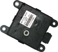
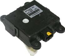
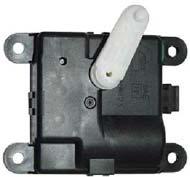
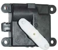
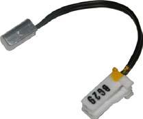
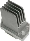
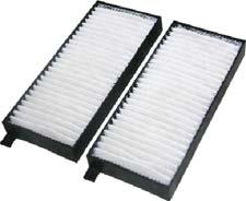
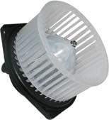
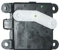
2 COMPONENTS 1. Blower and evaporator assembly 2. Actuator assembly - Intake 3. Air filter assembly 4. Cover - Air filter 5. Blower motor assembly 6. Resistor 7. Expansion valve assembly 9. Wiring assembly - Heater & evaporator 10. Heater assembly 11. Actuator assembly - Temperature 12. Actuator assembly - Mode 15. Heater assembly - PTC 20. Control assembly - Heater and A/C control 21. Bulb 22. Insert assembly - Ventilation 23. Sensor assembly - Humid and Incar 24. Sensor assembly - Intake
3 Condenser assembly 2. Compressor assembly - A/C 3. Hose assembly - Discharge 4. O-ring 5. O-ring 7. O-ring 8. O-ring 9. Hose assembly - Heater inlet 10. Hose assembly - Heater outlet 11. Pipe assembly - Joint 12. O-ring 13. O-ring 14. Pipe assembly - Liquid No Pipe assembly - Liquid No O-ring 17. Pipe assembly - Liquid No Hose assembly - Liquid 19. Receiver drier and bracket assembly 20. Nut 21. Nut 22. Bracket assembly - A/C compressor 23. Bolt 25. Bracket assembly - A/C compressor sub 26. Bolt 27. Hose - Drain 30. Sensor assembly - Receiver drier 50. Cap - Charge valve
4 Duct assembly - Console front 4. Screw 8. Duct assembly - Console rear 9. Duct assembly - Console foot 10. Duct assembly - Foot
5 TROUBLESHOOTING 1) Overview The FATC has a self-diagnosis function that can diagnose the system by itself. Before checking a component, be sure to check the fault code by using the self-diagnosis function. The selfdiagnosis consists of 6 steps. The temperature control dial (step 2 to 5) and fan speed dial (step 6) are used to enter each step of the self-diagnosis. The 6 steps of the self-diagnosis are: Step 1 - The VFD and all LED segments are checked for proper illumination. Step 2 - The sensors and air mix door are checked for proper operation. Step 3 - The position and condition of the air source door and mode door are checked. Step 4 - The actuator door position, fan speed and compressor operation are checked. Pressing the defroster switch after entering step 4 changes the diagnosis mode as follows: 41 -> 42 -> 43 -> 44 -> 45 -> 46 -> 41.

6 Step 5 - You can check that the temperature value from each temperature sensor is displayed properly in this step. Pressing the defroster switch changes the temperature value that appears on the display in the order as follows: 51 Ambient temperature display Interior temperature display Intake air temperature display Ambient temperature sensor Interior temperature sensor Intake air temperature sensor Step 6 - To enter the step 6 from 5, turn the fan speed dial lightly toward the right not using the temperature control dial. In this step, you can decrease or increase by up to 3 degrees from the temperature set on the A/C controller. 2) Self-diagnosis step (1) Step 1 Turn the ignition ON and press the OFF switch for 5 sec. or more within 10 sec. Then the first step of the self-diagnosis is started as shown in the below figure. 2. Display for checking VFD and all LED segments 1. Press OFF switch for 5 sec. or more


7 01-8 (2) Step 2 The sensors and air mix door are checked for proper operation in this step. When the step 2 is started, the number "2", which indicates that the system is in the step 2, apprears on the display and the check for sensors is performed. Once the check is done (for 10 to 20 sec.), the one digit number between 0 and 8 is added behind "2". "20" means there is no fault code. For the meaning of the rest of the numbers, refer to the description below. 1. Turn temperature dial lightly toward right to enter step 2 10 to 20 sec. 2. System starts sensor 3. Fault code for sensor check after "2" is appears and blinks displayed If "-" is displayed before "2", it means that the sensor for that flashing fault code has a short circuit. Ambient temperature sensor short circuited Fault code no. 1 (ambient temperature sensor) blinks twice Fault code no. 5 (sun sensor) blinks twice (fault codes appears sequentially) Refer to the following table for the meaning of the fault code.
8 (3) Step 3 In this step, you can check the position and condition of the air source door and mode door. To start step 3, turn the temperature control dial lightly toward the right and confirm that the number 3 appears on the display. It takes several tens of seconds to finish the check. If there is no fault code, "30" is displayed. And if there is a malfunction, the corresponding fault code is added as described in the step Turn temperature dial lightly toward right to enter step 3 Refer to the following table for the meaning of the fault code. 2. System starts 3. Fault code for sensor check after sensor appears "3" is displayed and blinks (30 is displayed when there is no fault)
9 01-10 (4) Step 4 In this step, the door position of each actuator, fan speed and operation of the compressor are checked. To enter this step, turn the temperature dial to the right in the step 3. The number, "41", appears on the display as soon as the step 4 is started. Press the defroster switch to change the diagnosis mode. 1. Turn temperature dial lightly toward right to enter step 4 Press Press Press Press Press Press Below table describes the detailed diagnosis items performed for each number. Check the corresponding component for proper operation according to the table. The voltage values listed in the table are the output voltage to operate the blower motor. The higher the voltage, the faster the fan speed is.

10 (5) Step 5 In this step, the system checks the temperature sensors used to control the A/C. To enter this step, turn the temperature dial to the right in the step 4. The ambient temperature appears on the display first and the interior temperature appears next and the intake air temperature last. The display changes the temperature value each time the defroster switch is pressed. 1. Turn temperature dial lightly toward right to enter step 5 Press Press Press Ambient temperature display Interior temperature display Intake air temperature display (6) Step 6 You can increase or decrease by up to 3 degrees from the set temperature. When entering the step 6 from 5, turn the fan speed dial. 2. Turn temperature control dial to adjust temperature 1. Turn fan speed dial to enter step 6 Step 6 starts Decrease by up to 3 degrees Increase by up to 3 degrees
11 01-12 (7) How to end self-diagnosis Turn the AUTO switch ON or turn OFF the ignition key. (8) When A/C system is faulty (Initial auto-diagnosis) The fault code for the faulty sensor is not displayed. Therefore you should start the self-diagnosis to check the system.
12 ) Trouble Diagnosis (1) Duct Temperature Sensor If the fault code for the duct temperature sensor (DTC 3) appears on the display, check the sensor as follows: A. Remove the duct temperature sensor and measure the resistance between the terminals of the connector (specification: approx. 2.2 kw at 25 ). If the resistance value is extremely high or low, replace the duct temperature sensor. B. If the result is not as specified, replace the duct temperature sensor. If the result is as specified, proceed to the next step. C. Turn the ignition switch to ON position and measure the voltage between the connector of the FATC controller and the duct temperature sensor (specification: approx. 2 V at 25 ). D. If the voltage cannot be measured, check the wiring for open circuit. If the result is as specified, replace the FATC controller. (2) Power Transistor If the fault code for the power transistor (DTC 6) is displayed, check as follows: A. Turn the ignition switch to ON position. B. Measure the voltage between the terminals of the blower motor while changing the fan speed from the lowest level to the highest level. C. The specified voltage value in each stage: D. If the voltage is out of specified value, check the wiring for open circuit. If the wiring is intact, replace the power transistor. (3) Thermo AMP Sensor (Intake Air Sensor) If the A/C is not turned on, check as follows: A. Remove the thermo AMP and measure the voltage between the terminals no. 1 and 2 of the connector. B. Check if the voltage is approx. 12 V when the output is ON and 0 V when the output is OFF. C. If the voltage value is not as specified, replace the thermo AMP. If the value is as specified, proceed to the next step. D. Turn the ignition switch to ON position and turn on the A/C by pressing the A/C button. And measure the voltage between the terminals A12 and A11 of the FATC controller connector (specification: approx. 12 V). E. If the voltage cannot be measured, check the wiring for open circuit. If the result is not as specified, replace the thermo AMP.
13 01-14 (4) Sun-load sensor A. Remove the sun-load sensor and measure the current between the terminals with the sensor exposed to direct sunlight. B. Measure the current again in the shade. If this value is lower than the measured value in the sunlight, the sensor is intact. C. Turn the ignition switch to the "ON" position. D. Measure the voltage between the terminals of the sun sensor at the FATC connector. (approx. 2.5 V under sunlight and approx. 4.8 V under shade) E. If the voltage cannot be measured, check the wiring for open circuit. If the result is not as specified, replace the FATC controller.


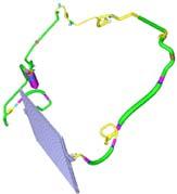
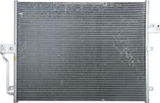
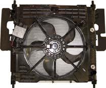
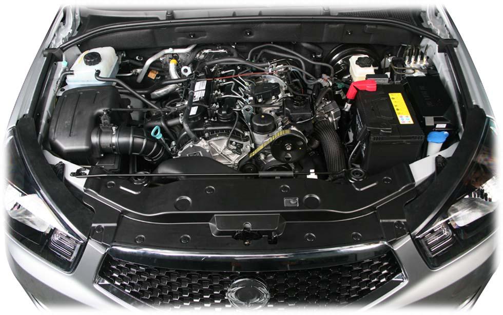
14 SYSTEM LAYOUT (EXTERIOR) Receiver drier A/C compressor Line and port Ambient temperature sensor A/C condenser Electric fan

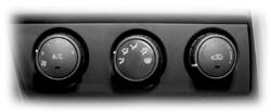
15 SYSTEM LAYOUT (INTERIOR) Sun-load sensor A/C controller A/C Module assembly Mode door actuator Air mix door actuator


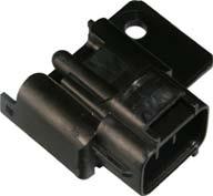
16 PTC Air source mode actuator Duct temperature sensor Thermo AMP Power transistor Blower motor assembly A/C filter
")
")
17 VENTILATION SYSTEM 1) Vent Ports Location - Interior 2) Configuration of Air Duct


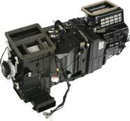
18 A/C MODULE 1) Components 1. Mode door actuator 2. PTC heater assembly 3. Duct temperature sensor 4. Air mix door actuator 5. Air source door actuator 6. A/C antibacterial filter 7. Blower motor 8. Power transistor 9. Thermo AMP 10. Mode door 11. Heater core 12. Air mix door 13. Evaporator 14. Air source door
 case Heater core Air mix door actuator Lower duct Mode door Heater unit (left) case Mode door actuator Mode door link")
19 ) Configuration Air source door case A/C filter Blower unit (upper) case Air source door actuator Blower motor assembly Blower unit (lower) case Evaporator Duct temperature sensor Thermo AMP Power Transistor A/C cable assembly Heater unit (right) case Heater core Air mix door actuator Lower duct Mode door Heater unit (left) case Mode door actuator Mode door link assembly
20 ) Wiring Layout Duct temperature sensor Mode door actuator Air source door actuator Power transistor Air mix door actuator Main wiring connector Interior temperature sensor Thermo AMP A/C controller unit Blower motor
21
22 A/C INPUT/OUTPUT DIAGRAM Below diagram shows the input/output mapping between the components of FATC A/C and A/C controller briefly. A/C compressor control by engine ECU In case of current vehicle models, the system turns ON or OFF the compressor switch according to the refrigerant pressure, ambient temperature and condenser temperature to protect the A/C circuits. However, for the vehicles equipped with DI engine, the engine ECU turns off the A/C compressor under below conditions, including those above. 1. Coolant temperature: 20 or less 2. Coolant temperature: 115 or more 3. For approx. 4 sec. after starting the engine 4. Engine speed: 650 rpm or less 5. Engine speed: 4,500 rpm or more 6. During abrupt acceleration for the vehicle equipped with manual transmission
 System Flow - \"Compression -> Condensation -> Expansion -> Evaporation\" 2) Functions (1) Compressor - - Condition: Gas Function: Circulates the refrigerant and increases the")
23 A/C COOLING CYCLE 1) System Flow - "Compression -> Condensation -> Expansion -> Evaporation" 2) Functions (1) Compressor - - Condition: Gas Function: Circulates the refrigerant and increases the pressure and temperature for easier evaporation. (2) Condenser - Condition: Gas/Liquid - Function: Cools and condenses the refrigerant by using ambient air to liquefy it under high pressure. (3) Receiver drier - - Condition: Gas/Liquid Function: Keeps the refrigerant free from moisture by separating/collecting the moisture from it. (4) Expansion valve - - Condition: Liquid/Liquefied gas Function: Performs adiabatic expansion and flow control for easier evaporation. (5) Evaporator - - Condition: Liquefied gas/gas Function: Cools the air by absorbing the heat from the air around the evaporator.
24 ) Description for Each Cycle (1) Compression - The evaporated refrigerant in the evaporator enters to the compressor. And the refrigerant gas is compressed until it can be liquefied at ambient temperature. - Thus, the low refrigerant pressure is maintained so that the liquid refrigerant can be evaporated actively at low temperature (around 0 ). (2) Condensation - The high pressure and high temperature gas (refrigerant) from the compressor is cooled down by the fresh air entered into the condenser. Then, this gas is converted to liquid and collected in the receiver drier. The heat generated from the high pressure refrigerant is dissipated to the ambient air, and it is called "heat of condensation". - The heat of condensation is the summation of the heat of vaporization (heat that the refrigerant absorbs from the inside of the vehicle) and the calorific value converted from the amount of work which is needed to compress. (3) Expansion - The liquid refrigerant lowers the pressure making its evaporation easily accomplished. This process (lowering the pressure to the level at which evaporation easily takes place before the liquid refrigerant is sent to the evaporator) is called "Adiabatic Expansion". - During adiabatic expansion, the expansion valve lowers the pressure of the refrigerant and determines the correct amount of refrigerant going into the air conditioning evaporator. That is, the amount of heat, which is needed to stop the evaporation, is determined according to the cooling load. The expansion valve detects this and regulates the amount of the refrigerant exactly. (4) Evaporator - The refrigerant is converted from liquid to gas in the evaporator. (The refrigerant in the form of fog in the evaporator is vaporized actively) - At this time the refrigerant, in the form of liquid, absorbs the heat in the air which is need for evaporation (latent heat) and is cooled down. Then the blower blows the cooled air inside the vehicle to lower the temperature. - There are liquid refrigerant from the expansion valve and evaporated refrigerant in the evaporator. - The evaporation temperature can be predicted from the evaporation pressure (i.e. relationship between saturation pressure and saturation temperature). - It is important to keep the pressure inside the evaporator low, so that the refrigerant is evaporated at low temperature to make sure the completely evaporated refrigerant is entered into the compressor.
25 A/C CIRCUIT DIAGRAM 1) A/C (AUTO): PWM Motor, Compressor, Air Mix Motor, Sun-Load Sensor, Intake Air Temperature Sensor (Thermo AMP)
26 ) A/C (AUTO): Blower motor (mode, air source), Inside air/humid sensor, Outside air temperature sensor
AIR CONDITIONER 1. SYSTEM LAYOUT AND COMPONENTS Air Conditioner Controller FATC. Manual air conditioner
 06-2 6810-01 1. SYSTEM LAYOUT AND COMPONENTS Type Air Conditioner Controller FATC Manual air conditioner Sun Sensor - Instrument Panel Upper Left It changes sun load coming through front windshield into
37. FATC (FULL AUTO TEMP. CONTROL) CIRCUIT 6810
 CIRCUIT 6810") 5156 6810 37. FATC (FULL AUTO TEMP. CONTROL) CIRCUIT 6810 1) CONDENSOR FAN, AIR MIX MOTOR, SUN SENSOR, WATER TEMP SENSOR A. CONNECTOR INFORMATION 6810 5157 Connector Number (Pin Number, Color) Connecting
5156 6810 37. FATC (FULL AUTO TEMP. CONTROL) CIRCUIT 6810 1) CONDENSOR FAN, AIR MIX MOTOR, SUN SENSOR, WATER TEMP SENSOR A. CONNECTOR INFORMATION 6810 5157 Connector Number (Pin Number, Color) Connecting
FULL AUTOMATIC TEMPERATURE CONTROL HEATING, VENTILATION AND AIR CONDITIONING SYSTEM
 SECTION 7D FULL AUTOMATIC TEMPERATURE CONTROL HEATING, VENTILATION AND AIR CONDITIONING SYSTEM FATC (Full Automatic Temperature Control) is full automatic heater and airconditioning system that detects
FULL AUTO TEMPERATURE CONTROL GENERAL 1. SPECIFICATIONS FULL AUTO TEMPERTURE CONTROL REXTON
 02-3 FULL AUTO TEMPERATURE CONTROL GENERAL 1. SPECIFICATIONS 02-4 OVERVIEW AND OPERATION PROCESS 1. FATC SYSTEM LAYOUT Configuration and Characteristic of A/C Controller 02-5 A/C System Related Devices
 Pagina 1 di 1 INSPECTION In-car air sensor is located at crash pad. It is installed with humidity sensor. It will detect interior, which will be used for discharge control, sensor failsafe, door control,
5. SELF DIAGNOSIS (ONLY FOR FATC AIR CONDITIONER)
") 18 6810 5. SELF DIAGNOSIS (LY FOR FATC AIR CDITIER) Self Diagnosis 1. Starting Self Diagnosis Turn the ignition switch to OFF position and press OFF switch for more than 5 seconds within 10 seconds. 1.
18 6810 5. SELF DIAGNOSIS (LY FOR FATC AIR CDITIER) Self Diagnosis 1. Starting Self Diagnosis Turn the ignition switch to OFF position and press OFF switch for more than 5 seconds within 10 seconds. 1.
A/C-HEATER SYSTEM - AUTOMATIC
 A/C-HEATER SYSTEM - AUTOMATIC 1996 Subaru SVX 1995-96 AUTOMATIC A/C-HEATER SYSTEMS Subaru SVX * PLEASE READ THIS FIRST * WARNING: To avoid injury from accidental air bag deployment, read and carefully
MANUAL CONTROL / SEMIAUTO TEMPERATURE CONTROL HEATING, VENTILATION AND AIR CONDITIONING SYSTEM
 SECTION 7C MANUAL CONTROL / SEMIAUTO TEMPERATURE CONTROL HEATING, VENTILATION AND AIR CONDITIONING SYSTEM CAUTION: Disconnect the negative battery cable before removing or installing any electrical unit
HEATER, AIR CONDITIONER AND VENTILATION
 55-1 HEATER, AIR CONDITIONER AND VENTILATION CONTENTS HEATER AND MANUAL AIR CONDITIONER...................... 3 GENERAL............................... 3 Outline of Change......................... 3 SERVICE
Volkswagen Golf > VW Rabbit GTI 2006-> (A5)
") Volkswagen Golf 5 2004-> VW Rabbit GTI 2006-> (A5) A/C Refrigerant System General information Note: General A/C refrigerant system servicing procedures (e.g., component/system descriptions, extracting
Volkswagen Golf 5 2004-> VW Rabbit GTI 2006-> (A5) A/C Refrigerant System General information Note: General A/C refrigerant system servicing procedures (e.g., component/system descriptions, extracting
DESCRIPTION AND OPERATION
 Page 1 of 10 DESCRIPTION AND OPERATION AIR DELIVERY DESCRIPTION AND OPERATION The air delivery description and operation is divided into five areas: HVAC Control Components Air Speed Air Delivery Recirculation
2001 Dodge Caravan Sport MANUAL A/C-HEATER SYSTEMS Caravan, Town & Country, & Voyager
 SPECIFICATIONS NOTE: Information for Caravan includes the Grand Caravan. SPECIFICATIONS Application Specification Compressor Type Nippondenso 10S20H Compressor Belt Tension (1) System Oil Capacity (2)
AIR CONDITIONER SECTION AC CONTENTS AUTO
 AIR CONDITIONER SECTION AC CONTENTS AUTO PRECAUTIONS AND PREPARATION SRS Airbag Pretensioner Seatbelt... 4 A/C Refrigerant HFC134a Handling... 4 Compressor Oil... 4 Tube Connection... 4 O-Ring Part Number...
Module 4: Climate Control
 ÂÂ ÂÂ Air-Conditioning Electronic Control Unit (ECU) Â Controlling Cabin Air Temperature Servo Motors Electric Servo Motors ÂÂ Air-Conditioning Electronic Control Unit (ECU) Automatic Climate Control Sensors
1. DO NOT HANDLE REFRIGERANT IN AN ENCLOSED AREA OR NEAR AN OPEN FLAME
 2006 Toyota 4Runner 4.0L Eng Limited 1Search AIR CONDITIONER REQUESTED INFORMATION PRECAUTION 1. DO NOT HANDLE REFRIGERANT IN AN ENCLOSED AREA OR NEAR AN OPEN FLAME 2. ALWAYS WEAR EYE PROTECTION Fig 1:
A/C-HEATER SYSTEM - AUTOMATIC
 A/C-HEATER SYSTEM - AUTOMATIC 1988 Toyota Celica 1988 Automatic A/C-Heater Systems Celica * PLEASE READ THIS FIRST * CAUTION: When discharging air conditioning system, use only approved refrigerant recovery/recycling
3.5 Air Conditioning (A/C) Contents
 Contents") 3.5 Air Conditioning (A/C) Contents 3.5 Model 210 Diagnosis Page Function Test................................... 11/1 Reading Actual Values............................ 12/1 Individual Flap Test...............................
3.5 Air Conditioning (A/C) Contents 3.5 Model 210 Diagnosis Page Function Test................................... 11/1 Reading Actual Values............................ 12/1 Individual Flap Test...............................
A/C-HEATER SYSTEM - AUTOMATIC
 A/C-HEATER SYSTEM - AUTOMATIC 1993 Toyota Celica 1993 Automatic A/C-Heater Systems Celica SPECIFICATIONS SPECIFICATIONS TABLE Application Specification Compressor Type 1.6L... Nippondenso 10PA15C 10-Cyl.
HEATING AND AIR CONDITIONING
 55-1 GROUP 55 HEATING AND AIR CONDITIONING CONTENTS GENERAL INFORMATION........ 55-3 MANUAL A/C DIAGNOSIS........ 55-4 INTRODUCTION TO HEATER, AIR CONDITIONING AND VENTILATION DIAGNOSIS........ 55-4 HEATER,
HEATING AND AIR CONDITIONING
 55-1 GROUP 55 HEATING AND AIR CONDITIONING CONTENTS GENERAL INFORMATION........ 55-3 MANUAL A/C DIAGNOSIS........ 55-4 INTRODUCTION TO MANUAL A/C DIAGNOSIS........................ 55-4 MANUAL A/C DIAGNOSTIC
VENTILATION SYSTEM SECTION VTL CONTENTS VENTILATION, HEATER & AIR CONDITIONER VTL-1 PRECAUTION... 2 PREPARATION... 4 FUNCTION DIAGNOSIS...
 VENTILATION, HEATER & AIR CONDITIONER SECTION VTL A VENTILATION SYSTEM B C D CONTENTS E PRECAUTION... 2 PRECAUTIONS... 2 Precaution for Supplemental Restraint System (SRS) "AIR BAG" and "SEAT BELT PRE-TEN-
How to Retrieve a DTC (Without HDS)
") How to Retrieve a DTC (Without HDS) The climate control unit has a self-diagnostic function. To run the self-diagnostic function, do the following: NOTE: Before troubleshooting the climate control system,
How to Retrieve a DTC (Without HDS) The climate control unit has a self-diagnostic function. To run the self-diagnostic function, do the following: NOTE: Before troubleshooting the climate control system,
Different oils are used in automotive A/C systems, based on the type of refrigerant. Polyalkylene Glycol (PAG) oil is used for R-134a refrigerant.
 oil is used for R-134a refrigerant.") Lubricants Automotive air conditioning lubricants are specially formulated because of how and where they operate. Air conditioning oils must be dry (having little or no water content) and mix with the
Lubricants Automotive air conditioning lubricants are specially formulated because of how and where they operate. Air conditioning oils must be dry (having little or no water content) and mix with the
3.10 Air Conditioning (A/C) Contents
 Contents") 3.10 Air Conditioning (A/C) Contents 3.10 Model 208 as of M.Y. 1998 Diagnosis Page Function Test................................... 11/1 Reading Actual Values............................ 12/1 Version Code...................................
3.10 Air Conditioning (A/C) Contents 3.10 Model 208 as of M.Y. 1998 Diagnosis Page Function Test................................... 11/1 Reading Actual Values............................ 12/1 Version Code...................................
3.6 Air Conditioning (A/C) Contents
 Contents") 3.6 Air Conditioning (A/C) Contents 3.6 Model 140 as of MY 1996 Page Diagnosis Function Test.................................. 11/1 Reading Sensor Values........................... 12/1 Individual Flap
3.6 Air Conditioning (A/C) Contents 3.6 Model 140 as of MY 1996 Page Diagnosis Function Test.................................. 11/1 Reading Sensor Values........................... 12/1 Individual Flap
ENGINE COOLING SYSTEM GENERAL 1. GENERAL SPECIFICATIONS ENGINE COOLING SYSTEM. undefined
 211001 043 GENERAL 1. GENERAL SPECIFICATIONS 211001 044 211001 2. FASTENER TIGHTENING SPECIFICATIONS 211001 045 OVERVIEW AND OPERATION PROCESS 1. COMPONENT LOCATOR 1. Reserver Tank 2. Deaeration Tube 3.
Program IV: ProStar TM. Performance A/C International. Series. Study Guide Performance A/C Program IV: International ProStar Series TMT
 Performance A/C International A N AV I S TA R C O M PA N Y Program IV: ProStar TM Study Guide TMT-160701 Series Study Guide Performance A/C Program IV: International ProStar Series TMT-160701 2007 International
HEATER, AIR CONDITIONING AND VENTILATION
 55-1 GROUP 55 HEATER, AIR CONDITIONING AND VENTILATION CONTENTS GENERAL INFORMATION 55-3 FASTENER TIGHTENING SPECIFICATIONS 55-5 GENERAL SPECIFICATIONS 55-5 SERVICE SPECIFICATIONS 55-5 LUBRICANTS 55-5
3.3 Air Conditioning (A/C) Model 202
 Model 202") Notes for Diagnosis The A/C pushbutton control module (N22) has DTC memory and data output.the diagnostic trouble codes and data are displayed via the temperature display window (arrow). The stored DTC
Notes for Diagnosis The A/C pushbutton control module (N22) has DTC memory and data output.the diagnostic trouble codes and data are displayed via the temperature display window (arrow). The stored DTC
A/C SYSTEM GENERAL DIAGNOSTIC PROCEDURES
 Article Text ARTICLE BEGINNING 1993 AIR CONDITIONING & HEAT A/C General Diagnostic Procedures Diagnosis is an important first step in A/C system servicing. To save time and effort, systems should be carefully
2001 IMPREZA SERVICE MANUAL QUICK REFERENCE INDEX
 00 IMPREZA SERVICE MANUAL QUICK REFERENCE INDEX BODY SECTION HVAC SYSTEM (HEATER, VENTILATOR AND A/C) HVAC SYSTEM (AUTO A/C) (DIAGNOSTICS) AIRBAG SYSTEM AC AC AB This service manual has been prepared to
HEATER, AIR CONDITIONING AND VENTILATION
 55-1 GROUP 55 HEATER, AIR CONDITIONING AND VENTILATION CONTENTS GENERAL INFORMATION 55-3 FASTENER TIGHTENING SPECIFICATIONS 55-5 GENERAL SPECIFICATIONS 55-5 SERVICE SPECIFICATIONS 55-5 LUBRICANTS 55-5
AUTOMATIC AIR CONDITIONER > COMPONENT DIAGNOSIS > BLOWER MOTOR CONTROL SYSTEM > SYSTEM DESCRIPTION > SYSTEM DESCRIPTION
 2008 Nissan Armada 5.6L Eng SE HEATER & AIR CONDITIONING CONTROL SYSTEM MOTOR CONTROL SYSTEM > SYSTEM DESCRIPTION > SYSTEM DESCRIPTION Component Parts Blower speed control system components are: A/C auto
HEATER & AIR CONDITIONING CONTROL SYSTEM
 VENTILATION, HEATER & AIR CONDITIONER SECTION HAC A HEATER & AIR CONDITIONING CONTROL SYSTEM B C D CONTENTS E WITH COLOR DISPLAY BASIC INSPECTION... 5 INSPECTION AND ADJUSTMENT... 5 Operational Check (Front)...5
A/C-HEATER SYSTEM - AUTOMATIC
 A/C-HEATER SYSTEM - AUTOMATIC 1994 Volvo 960 1994 Auto. A/C-Heater System Volvo 960 A/C SYSTEM SPECIFICATIONS AUTOMATIC A/C SYSTEM SPECIFICATIONS TABLE Application Specification Compressor Type... Sanden
3.2 Air Conditioning (A/C) Model 140 up to M.Y. 1995
 Model 140 up to M.Y. 1995") Diagnosis Memory P83-3271-13B Notes for Diagnosis The A/C pushbutton control module (N22) has DTC memory and the capability to display the codes via the temperature display windows (arrows) on the A/C
Diagnosis Memory P83-3271-13B Notes for Diagnosis The A/C pushbutton control module (N22) has DTC memory and the capability to display the codes via the temperature display windows (arrows) on the A/C
TSB #: 53 Date: 2/11/2011 HOLDEN (DELPHI) VARIABLE STROKE COMPRESSOR DIAGNOSIS STEP ACTION RESULT YES NO
 VARIABLE STROKE COMPRESSOR DIAGNOSIS STEP ACTION RESULT YES NO") HOLDEN (DELPHI) VARIABLE STROKE COMPRESSOR DIAGSIS TSB #: 53 Date: 2/11/2011 Initial Once Read: Even though the Holden variable stroke compressor manufactured by Delphi has been in the Australian market
HOLDEN (DELPHI) VARIABLE STROKE COMPRESSOR DIAGSIS TSB #: 53 Date: 2/11/2011 Initial Once Read: Even though the Holden variable stroke compressor manufactured by Delphi has been in the Australian market
LIST OF OPERATION METHODS
 0.5 Seconds 0.5 Seconds AT0716 DI1747 DIB6T02 PRECHECK 1. Warning for A/C compressor lock If compressor lock occurs during A/C operation, the A/C switch indicator on the A/C control assembly starts blinking.
MULTIPOINT FUEL INJECTION (MPI) <4G9>
 <4G9>") MULTIPOINT FUEL INJECTION (MPI) 13C-1 MULTIPOINT FUEL INJECTION (MPI) CONTENTS GENERAL................................. 2 Outline of Changes............................ 2 GENERAL INFORMATION...................
MULTIPOINT FUEL INJECTION (MPI) 13C-1 MULTIPOINT FUEL INJECTION (MPI) CONTENTS GENERAL................................. 2 Outline of Changes............................ 2 GENERAL INFORMATION...................
211 Climate Control 219 PP HVAC (TWK)
") 211 Climate Control 219 PP HVAC (TWK) 8-30-02 1 These technical training materials are current as of the date noted on the materials, and may be revised or updated without notice. Always check for revised
211 Climate Control 219 PP HVAC (TWK) 8-30-02 1 These technical training materials are current as of the date noted on the materials, and may be revised or updated without notice. Always check for revised
 Page 1 of 50 Section 412-00: Climate Control System General Information DIAGSIS AND TESTING 1997 Mark VIII Workshop Manual Climate Control System Special Service Tool(s) 73 Digital Multimeter 105-R0051
13A-1 FUEL CONTENTS MULTIPOINT FUEL INJECTION (MPI) FUEL SUPPLY... 13B
 FUEL SUPPLY... 13B") 13A-1 FUEL CONTENTS MULTIPOINT FUEL INJECTION (MPI)... 13A FUEL SUPPLY... 13B 13A-2 MULTIPOINT FUEL INJECTION (MPI) CONTENTS GENERAL INFORMATION... 3 SERVICE SPECIFICATIONS... 6 SEALANT... 6 SPECIAL TOOLS...
13A-1 FUEL CONTENTS MULTIPOINT FUEL INJECTION (MPI)... 13A FUEL SUPPLY... 13B 13A-2 MULTIPOINT FUEL INJECTION (MPI) CONTENTS GENERAL INFORMATION... 3 SERVICE SPECIFICATIONS... 6 SEALANT... 6 SPECIAL TOOLS...
2015 F-250, 350, 450, 550 Super Duty DESCRIPTION AND OPERATION Procedure revision date: 04/28/2016. Climate Control System
 Page 1 of 9 412-00 Climate Control System General Information and Diagnostics Climate Control System 2015 F-250, 350, 450, 550 Super Duty DESCRIPTION AND OPERATION Procedure revision date: 04/28/2016 WARNING:
SECTION Climate Control System - General Information
 412-00-i Climate Control System - General Information 412-00-i SECTION 412-00 Climate Control System - General Information CONTENTS PAGE DIAGNOSIS AND TESTING Climate Control System... 412-00-2 Inspection
HEATER, AIR CONDITIONING AND VENTILATION
 - GROUP HEATER, AIR CONDITIONING AND VENTILATION CONTENTS GENERAL DESCRIPTION......... -3 SERVICE PRECAUTIONS......... - CAUTION LABELS................... -........ - INTRODUCTION TO HEATER, AIR CONDITIONING
Layout Diagrams. Section CONTENTS. General Layout Diagram Floor / Roof Engine Compartment Door
 1-1 Section 1 Layout Diagrams CONTENTS General Layout Diagram...1-3 Engine Compartment...1-4 Engine / Transmission...1-6 Floor / Roof...1-16 Door...1-18 Boot Compartment...1-20 Instrument Panel...1-10
1996 AUTOMATIC A/C-HEATER SYSTEMS Acura Automatic A/C Systems
 Article Text Saturday, January 23, 1999 06:32PM ARTICLE BEGINNING 1996 AUTOMATIC A/C-HEATER SYSTEMS Acura Automatic A/C Systems A4 * PLEASE READ THIS FIRST * WARNING: To avoid injury from accidental air
VALEO HEVAC (P38 NRR) - System Overview
 - System Overview") VALEO HEVAC (P38 NRR) - System Overview Custom Manufactured by Valeo for the P38 Range Rover as an Air condition control module option on everything except the very base model, which has only 3 rotary
VALEO HEVAC (P38 NRR) - System Overview Custom Manufactured by Valeo for the P38 Range Rover as an Air condition control module option on everything except the very base model, which has only 3 rotary
This vehicle uses HFC 134a (R 134a) refrigerant, which does not contain chlorofluorocarbons. Pay attention to the following service items:
 refrigerant, which does not contain chlorofluorocarbons. Pay attention to the following service items:") HEATING AND A/C SYSTEM DESCRI... 2007 CIVIC Heating and A/C System Description The air conditioning (A/C) system removes heat from the passenger compartment by transferring heat from the ambient air to
HEATING AND A/C SYSTEM DESCRI... 2007 CIVIC Heating and A/C System Description The air conditioning (A/C) system removes heat from the passenger compartment by transferring heat from the ambient air to
EFFICIENT SLEEPER COMFORT. Volvo s Battery-powered Parking Cooler Option
 EFFICIENT SLEEPER COMFORT Volvo s Battery-powered Parking Cooler Option Cooling comfort and anti-idle value. Most environmentally-friendly and efficient solution for sleeper comfort Overnight comfort without
Jeep Wrangler TJ 4.0 LITER Installation instructions
 www.jeepair.com 2000-2001 Jeep Wrangler TJ 4.0 LITER Installation instructions Important information about your system, and warranty DO NOT ADD ANY OIL TO ANY PART OF THE SYSTEM. DO NOT USE THE SIGHT GLASS
A/C SYSTEM SPECIFICATIONS
 A/C SYSTEM SPECIFICATIONS A/C-HEATER SYSTEM - MANUAL 1997 Manual A/C-Heater System WARNING: To avoid injury from accidental air bag deployment, read and follow all SERVICE PRECAUTIONS and DISABLING & ACTIVATING
DESCRIPTION AND OPERATION
 Your Current Vehicle: 1998 Ford Explorer Top / Heating, Ventilation, & Air Conditioning / Control Components / DESCRIPTION AND OPERATION DESCRIPTION AND OPERATION SECTION 412-04: Control Components 1998
TROUBLE DIAGNOSIS. Press (DEF) switch a third time. Temperature detected by intake sensor is indicated on the display ( F for
 switch a third time. Temperature detected by intake sensor is indicated on the display ( F for") 8. SELF-DIAGNOSIS STEP 5: TEMPERATURE OF EACH SENSOR IS CHECKED 1. Rotate the temperature control dial clockwise (driver) to STEP 5. 2. Code No. 51 appears on the display. >> GO TO 9. 9. CHECK AMBIENT
8. SELF-DIAGNOSIS STEP 5: TEMPERATURE OF EACH SENSOR IS CHECKED 1. Rotate the temperature control dial clockwise (driver) to STEP 5. 2. Code No. 51 appears on the display. >> GO TO 9. 9. CHECK AMBIENT
ON-VEHICLE INSPECTION
 32 SUSPENSION CONTROL AIR SUSPENSION SYSTEM ON-VEHICLE INSPECTION 1. CHECK FLUID LEAKAGE Check the connections of tube and parts for fluid leakage. : Supply parts only C099149E01 SUSPENSION CONTROL AIR
INSTALLATION INSTRUCTIONS
 INSTALLATION INSTRUCTIONS Accessory Application Publications No. AIR CONDITIONER CIVIC 2- AND 4-DOOR AII 24158 Issue Date SEP 2002 What s New The installation instructions for the 2003 Civic A/C are the
PERFECT FIT SERIES IN-DASH HEAT/ COOL/ DEFROST 1969 CHEVROLET CAMARO/ FIREBIRD NOTE: INSTRUCTIONS DEPICT CAMARO
 specializing in AIR CONDITIONING, PARTS AND SYSTEMS for your classic vehicle PERFECT FIT SERIES IN-DASH HEAT/ COOL/ DEFROST 1969 CHEVROLET CAMARO/ FIREBIRD NOTE: INSTRUCTIONS DEPICT CAMARO CONTROL & OPERATING
E - THEORY/OPERATION - TURBO
 E - THEORY/OPERATION - TURBO 1995 Volvo 850 1995 ENGINE PERFORMANCE Volvo - Theory & Operation 850 - Turbo INTRODUCTION This article covers basic description and operation of engine performance-related
DIM Heating and Air Conditioning
 2014 NATEF JOB TASKS COMPLETION REQUIREMENT: P1-95% P2-70% P3-25% Student Name: DETAILED COURSE CONTENT VI. HEATING, VENTILATION, & AIR CONDITIONING A. HVAC SYSTEMS -- The student will be able to: P1 P2
ARTICLE BEGINNING * PLEASE READ THIS FIRST * DESCRIPTION OPERATION ATC COMPUTER BLEND-AIR DOOR ACTUATOR CONTROL PANEL
 A/C-HEATER SYSTEM - AUTOMATIC Article Text 1989 Chrysler LeBaron Sedan For m m m m m Copyright 1998 Mitchell Repair Information Company, LLC Thursday, July 03, 2003 10:15AM ARTICLE BEGINNING 1989 AUTOMATIC
Position of Parts in Engine Compartment
 ELECTRICAL WIRING ROUTING [3S GTE] Position of Parts in Engine Compartment A 1 A/C Ambient Temp. Sensor D 1 Date Link Connector 1 (Check Connector) A 2 A/C Condenser Fan Motor D 2 Distributor A 4 A/C Magnetic
RETRIEVING DIAGNOSTIC TROUBLE CODES
 Page 1 of 13 SELF-DIAGNOSTICS A/C-heater control assembly monitors system circuits and stores a code in memory if a problem is detected. All codes are stored in memory except Code 2 Malfunction is current
DIAGNOSIS AND TESTING
 412-00-1 Climate Control System - General Information 412-00-1 DIAGNOSIS AND TESTING Climate Control System Refer to Wiring Diagrams Cell 54, Air Conditioner/Heater for schematic and connector information.
DIAGNOSIS AND TESTING
 412-00-1 Climate Control System - General Information 412-00-1 DIAGNOSIS AND TESTING Climate Control System Refer to Wiring Diagrams Cell 54, Air Conditioning/Heater for schematic and connector information.
CONFIGURATION DIAGRAMS
 GROUP 80 CONFIGURATION DIAGRAMS CONTENTS OVERALL CONFIGURATION DIAGRAM...................... 80-2......... 80-3 .. 80-3 .. 80-5 ...... 80-7 INSTRUMENT PANEL............ 80-9 FLOOR
SOUL GDI REPAIR AND MAINTENANCE
 SOUL 2013-1.6 GDI REPAIR AND MAINTENANCE (First Numbers are page number within section - Numbers in parenthesis are overall document page) GENERAL INFORMATION (23 PAGES) 01-07 (01-07): Identification Number
DI-377 SUPPLEMENTAL RESTRAINT SYSTEM DI58G-01 PRE-CHECK
 W01632 PRECHECK DI377 DI58G01 1. SRS WARNING LIGHT CHECK (a) Turn the ignition switch to the ACC or ON position and check that the SRS warning light lights up. (b) Check that the SRS warning light goes
Volkswagen > Golf, Jetta, GTI, Cabrio > Heating Air Conditioning 87 - A/C controls and mechanical components, servicing
 x-ebahn:///c:/program%20files/ebahn/data/vw-a-a3-h28ebn/vw/a/a3/repair%20ma Page 1 of 13 Volkswagen > Golf, Jetta, GTI, Cabrio > 1993-2002 Heating Air Conditioning 87 - A/C controls and mechanical components,
1. Disconnect the battery. This is important! This will prevent air bag deployment.
 PARTS PACKING LIST Evaporator assembly Drain tube Plastic air plug Hardware package 11040 3601 W. Clarendon Phoenix, Arizona 85019 (602) 233-0090 800-648-4475 www.ackits.com 2003-4 Jeep Wrangler EVAPORATOR
2004 TSX - How to Troubleshoot the Climate Control System
 2004 TSX - How to Troubleshoot the Climate Control System How to Check for DTCs with the HDS 1. Make sure the ignition switch is OFF. 2. Connect the HDS to the data link connector (DLC) (A) located under
PERFECT FIT IN-DASH HEAT/ COOL/ DEFROST FORD FAIRLANE & CROWN VICTORIA
 PERFECT FIT IN-DASH HEAT/ COOL/ DEFROST 1955-56 FORD FAIRLANE & CROWN VICTORIA CONTROL & OPERATING INSTRUCTIONS The controls on your new Perfect Fit system, offer complete comfort capabilities in virtually
EMISSION CONTROL (AUX. EMISSION CONTROL DEVICES) H4DOTC
 H4DOTC") EMISSION CONTROL (AUX. EMISSION CONTROL DEVICES) H4DOTC SYSTEM OVERVIEW 1. System Overview There are three emission control systems, which are as follows: Crankcase emission control system Exhaust emission
EMISSION CONTROL (AUX. EMISSION CONTROL DEVICES) H4DOTC SYSTEM OVERVIEW 1. System Overview There are three emission control systems, which are as follows: Crankcase emission control system Exhaust emission
DTC P0110 Intake Air Temperature Circuit. DTC P0112 Intake Air Temperature Circuit Low Input. DTC P0113 Intake Air Temperature Circuit High Input
 DI534 DIAGNOSTICS EINE (2UZFE) DIA8003 DTC P0110 Intake Air Temperature Circuit DTC P0112 Intake Air Temperature Circuit Low Input DTC P0113 Intake Air Temperature Circuit High Input CIRCUIT DESCRIPTION
Jeep Wrangler 4.0 Liter TJ Jeep Wrangler 2.5 Liter TJ Installation instructions
 TM www.jeepair.com 1999 Jeep Wrangler 4.0 Liter TJ 1999-2001 Jeep Wrangler 2.5 Liter TJ Installation instructions Kit Information After 1994 every vehicle was designed for R134a refrigerant. The Jeep kit
DIAGNOSIS MADE EASY PART OF COOLING SYSTEM TROUBLE SHOOTING
 DIAGNOSIS MADE EASY PART OF COOLING SYSTEM TROUBLE SHOOTING DIAGNOSE CAR PROBLEMS QUICKLY AND RELIABLY USING GATES INTUITIVE QUESTION TREE DIAGNOSTIC PROCESS The purpose of this booklet is to provide
Wiring diagrams on page 29 are for reference only. For detailed vehicle wiring refer to Navistar documents.
 1 10/2014 REV 7 !!Attention!! Before performing diagnostics: Wiring diagrams on page 29 are for reference only. For detailed vehicle wiring refer to Navistar documents. Check for Fault Codes using the
PRE CHECK 1. SRS WARNING LIGHT CHECK
 H08442 PRECHECK DI287 DI4L104 1. SRS WARNING LIGHT CHECK (a) Turn the ignition switch to the ACC or ON position and check that the SRS warning light lights up. (b) Check that the SRS warning light goes
5/12/2018 Climate Control - Control Components - Description and Operation 2009 Ford F-150 MotoLogic
 2009 F-150 Subarticles Report a problem with this article Electronic Manual Temperature Control (EMTC) Dual-Zone Electronic Automatic Temperature Control (EATC) SECTION 412-01: Climate Control 2009 F-150
AIR CONDITIONING SYSTEM
 AC-1 AIR CONDITIONING SYSTEM GENERAL INFORMATION DESCRIPTION TROUBLESHOOTING PREPARATION REFRIGERATION SYSTEM DRIVE BELT REFRIGERATION LINES COMPRESSOR RECEIVER CONDENSOR COOLING UNIT COOL/ICE BOX EVAPORATORS
Chevrolet Truck Install Instructions. This kit is designed for the Chevrolet or GMC trucks without factory air conditioning.
 1967-1972 Chevrolet Truck Install Instructions This kit is designed for the 1967-1972 Chevrolet or GMC trucks without factory air conditioning. Glove box Heater box Heater box firewall cover Controls and
Jeep Wrangler TJ 4.0 LITER Installation instructions
 www.jeepair.com 2002-2004 Jeep Wrangler TJ 4.0 LITER Installation instructions Kit Information These directions are for 2002-2006 model Jeep Wranglers. After 1994 every vehicle was designed for R134a refrigerant.
SECTION 1D1 M162 ENGINE COOLING
 SECTION 1D1 M162 ENGINE COOLING CAUTION: Disconnect the negative battery cable before removing or installing any electrical unit or when a tool or equipment could easily come in contact with exposed electrical
Heater capacity 250W 13.5V Injector System pressure 1800 bar High pressure fuel pump. Normal operating temperature. Operating temperature
 221001 033 1. SPECIFICATIONS Description Fuel Specification Diesel Fuel filter Type Fuel heater + priming pump + water separator integrated type Filter type Changeable filter element type Change interval
TABLE OF CONTENTS Subject Page
 TABLE OF CONTENTS Subject Page Control Panel................................................2 Control Module..............................................6 Substitute Value Operation......................................7
G - TESTS W/CODES Nissan 240SX * PLEASE READ THIS FIRST * INTRODUCTION SELF-DIAGNOSTIC SYSTEM DESCRIPTION HARD FAILURES INTERMITTENT FAILURES
 G - TESTS W/CODES 1990 Nissan 240SX 1990 ENGINE PERFORMANCE Self-Diagnostics Nissan 240SX and Axxess * PLEASE READ THIS FIRST * NOTE: This article has been revised according to Technical Service Bulletin
Jeep Wrangler TJ. Complete Air Conditioning System. Slide Control Head. Installation instructions
 WWW.JEEPAIR.COM 1996-1998 Jeep Wrangler TJ Complete Air Conditioning System Slide Control Head Installation instructions Kit Information After 1994 every vehicle was designed for R134a refrigerant. The
Power Sliding Door (PSD) Diagnostic Approach. Fixing Intermittent Malfunctions. Power Sliding Door (PSD) Diagnostic Information
 Diagnostic Approach. Fixing Intermittent Malfunctions. Power Sliding Door (PSD) Diagnostic Information") Power Sliding Door (PSD) Diagnostic Information Power Sliding Door (PSD) The power sliding door (PSD) provides built-in diagnostics. This assists the service technicians during troubleshooting. The PSD
Power Sliding Door (PSD) Diagnostic Information Power Sliding Door (PSD) The power sliding door (PSD) provides built-in diagnostics. This assists the service technicians during troubleshooting. The PSD
5. Engine Control Module (ECM) I/O Signal
 I/O Signal") 5. A: ELECTRICAL SPECIFICATION B134 B135 B136 B137 17 16 15 14 13 12 11 10 9 8 27 26 25 24 23 22 21 20 19 18 34 33 32 31 30 29 28 19 18 17 16 15 14 13 12 11 10 9 8 27 26 25 24 23 22 21 20 35 34 33 32 31
5. A: ELECTRICAL SPECIFICATION B134 B135 B136 B137 17 16 15 14 13 12 11 10 9 8 27 26 25 24 23 22 21 20 19 18 34 33 32 31 30 29 28 19 18 17 16 15 14 13 12 11 10 9 8 27 26 25 24 23 22 21 20 35 34 33 32 31
G ELECTRICAL WIRING ROUTING
 G ELECTRICAL WIRING ROUTING Position of Parts in Engine Compartment A 1 A/C Ambient Temp. Sensor A 2 A/C Condenser Fan Motor A 3 A/C Magnetic Clutch and Lock Sensor A 4 A/C Triple Pressure SW (A/C Dual
PRE CHECK. (b) In case of not using LEXUS hand held tester : Check the DTC. (1) Disconnect the short pin from DLC1.
 In case of not using LEXUS hand held tester : Check the DTC. (1) Disconnect the short pin from DLC1.") DI 412 DIAGNOSTICS F02852 PRE CHECK DI28T 01 1. DIAGNOSIS SYSTEM (a) Check the warning lights and buzzer. (1) Release parking brake pedal. (2) When the ignition switch is turned, check that the ABS and
DI 412 DIAGNOSTICS F02852 PRE CHECK DI28T 01 1. DIAGNOSIS SYSTEM (a) Check the warning lights and buzzer. (1) Release parking brake pedal. (2) When the ignition switch is turned, check that the ABS and
Acura Plus Comprehensive & Major Component Coverage
 Acura Plus Comprehensive & Major Component Coverage ENGINE Cylinder block and all internal parts Cylinder heads and all internal parts Engine mounts Engine seals and gaskets Flywheel Intake and exhaust
01 02B ON-BOARD DIAGNOSTIC [ENGINE CONTROL SYSTEM (FS)]
![01 02B ON-BOARD DIAGNOSTIC [ENGINE CONTROL SYSTEM (FS)]](/thumbs/80/80600627.jpg "01 02B ON-BOARD DIAGNOSTIC [ENGINE CONTROL SYSTEM (FS)]") ON-BOARD DIAGNOSTIC [ENGINE CONTROL SYSTEM (FS)] CONTROL SYSTEM WIRING DIAGRAM [FS]............................ 2 CONTROL SYSTEM DEVICE AND CONTROL RELATIONSHIP CHART [FS]........ 4 Engine Control System............
ON-BOARD DIAGNOSTIC [ENGINE CONTROL SYSTEM (FS)] CONTROL SYSTEM WIRING DIAGRAM [FS]............................ 2 CONTROL SYSTEM DEVICE AND CONTROL RELATIONSHIP CHART [FS]........ 4 Engine Control System............
P0030, P0036, -- P0135, P0141, P0155, P0161 P0030, P0036, P0050, P0056, P0135, P0141,
 Page 1 of 6 2008 Pontiac G8 DTC P0030, P0036, P0053, P0054, P0135, or P0141 Diagnostic Instructions Perform the Diagnostic System Check - Vehicle prior to using this diagnostic procedure. Review Strategy
EMISSION CONTROL (AUX. EMISSION CONTROL DEVICES) H4SO
 H4SO") EMISSION CONTROL (AUX. EMISSION CONTROL DEVICES) H4SO SYSTEM OVERVIEW 1. System Overview There are three emission control systems, which are as follows: Crankcase emission control system Exhaust emission
EMISSION CONTROL (AUX. EMISSION CONTROL DEVICES) H4SO SYSTEM OVERVIEW 1. System Overview There are three emission control systems, which are as follows: Crankcase emission control system Exhaust emission
SECTION 9A BODY WIRING SYSTEM
 SECTION 9A BODY WIRING SYSTEM Caution: Disconnect the negative battery cable before removing or installing any electrical unit or when a tool or equipment could easily come in contact with exposed electrical
PRE-CHECK USA: DI-224 DLC1 E 1 ABS WITH EBD & BA & TRAC & VSC SYSTEM 2WD: CANADA: 4WD:
 DI224 2WD: 4WD: USA: CANADA: F14323 PRECHECK DI8XO02 1. DIAGNOSIS SYSTEM (a) Inspect the battery positive voltage. Battery positive voltage: 10 14 V (b) Check the warning lights and buzzer. (1) Release
ENGINE AND EMISSION CONTROL
 17-1 GROUP 17 ENGINE AND EMISSION CONTROL CONTENTS ENGINE CONTROL.......... 17-3 GENERAL DESCRIPTION...... 17-3 ENGINE CONTROL SYSTEM DIAGNOSIS.................. 17-3 INTRODUCTION TO ENGINE CONTROL SYSTEM
COMPONENT LOCATIONS GROUP CONTENTS FUSIBLE LINK, FUSE AND IOD OR STORAGE CONNECTOR RELAY OTHER DEVICES...
 70-1 GROUP 70 COMPONENT LOCTIONS CONTENTS RELY........................ 70-2 OTHER DEVICES............... 70-3 CONTROL UNIT................. 70-4 INSPECTION TERMINL......... 70-7 SENSOR.......................
DTC P0100 MASS OR VOLUME AIR FLOW CIRCUIT DTC P0102 MASS OR VOLUME AIR FLOW CIRCUIT LOW INPUT DTC P0103 MASS OR VOLUME AIR FLOW CIRCUIT HIGH INPUT
 0564 DIAGNOSTICS DTC P0100 MASS OR VOLUME AIR FLOW CIRCUIT 059VF10 DTC P0102 MASS OR VOLUME AIR FLOW CIRCUIT LOW INPUT DTC P0103 MASS OR VOLUME AIR FLOW CIRCUIT HIGH INPUT CIRCUIT DESCRIPTION The MAF (Mass
RS 44 SUPPLEMENTAL RESTRAINT SYSTEM HINT:
 RS44 DIAGNOSIS INSPECTION SRS warning light check (a) Turn the ignition switch to ACC or ON and check that the SRS warning light lights up. (b) Check that the SRS warning light goes out after approx. 6