AIR CONDITIONER 1. SYSTEM LAYOUT AND COMPONENTS Air Conditioner Controller FATC. Manual air conditioner
|
|
|
- Daniel Matthews
- 5 years ago
- Views:
Transcription


1 SYSTEM LAYOUT AND COMPONENTS Type Air Conditioner Controller FATC Manual air conditioner Sun Sensor - Instrument Panel Upper Left It changes sun load coming through front windshield into current to input to FATC controller. AQS Switch Compressor AQS Sensor and Ambient Temperature Sensor AQS sensor A function that turns on/off the air source selection and air quality system. Ambient temperature sensor This sensor is installed at the front bottom of engine compartment. This changes the air source mode by detecting the air pollution and the ambient temperature.


 Absorbs moisture in the refrigerant and reserves refrigerant to")

2 06-3 Air Conditioner Module Assembly - Inside of Instrument Panel Heater Unit Side Coolant temperature sensor Air mix door actuator Air source door actuator Mode door actuator Air conditioner filter Power transistor Air conditioner controller Main wiring connector Thermo AMP Blower Unit Side Condenser Installed in front of vehicle and condenses vapor refrigerant into low temperature and high pressure liquid refrigerant. Receiver Drier (LH) Engine ECU (Passenger Footstep) Coolant Temperature Sensor (On Engine) Absorbs moisture in the refrigerant and reserves refrigerant to supply smoothly. Detects A/C switch position, coolant temperature, engine condition and driving condition to control the air conditioner. A sensor that detects coolant temperature and transmits it to engine ECU.


3 VENTILATION SYSTEM 1) Locations of Vents 2) Air Duct

4 06-5 3) Air Duct Layout Mode door actuator Air mix door actuator Coolant temperature sensor Air source door actuator Main wiring connector Blower motor A/C unit and active incar/ humidity sensor Thermo AMP Power transistor Front Air Conditioner Module Wiring Layout Mode door actuator Coolant temperature detection sensor Air source door actuator Power transistor Main wire connector Air mix door actuator Active incar sensor (interior temperature sensor) and humidity sensor Thermo AMP Blower motor Air conditioner controller unit


5 MODULE AND SENSORS 1) Locations Coolant Temperature Sensor Air Source Door Actuator Air Conditioner Filter Air mix door actuator Mode Door Actuator Thermo AMP A/C Controller Unit Active Incar Sensor (Humidity Sensor) Power Transistor/ Blower Motor Power transistor Active incar and humidity sensor Blower motor
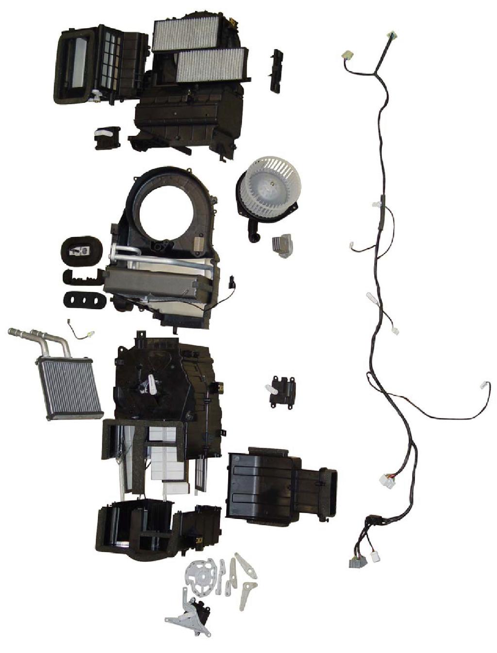
6 06-7 2) Components
7 06-8 3) PTC Heater and FFH Heater Layout (1) PTC Heater Assembly Layout (2) FFH Heater Assembly Layout
8 SYSTEM DIAGRAM This figure shows the input and output system between FACT A/C components and A/C controller. 1) Air Conditioner Compressor Control by Engine ECU In case of conventional vehicle models, the system turns ON/OFF the compressor switch according to refrigerant pressure, ambient temperature and condenser temperature to protect air conditioner circuits. However, for the vehicle equipped with DI engine, the engine ECU turns off air conditioner compressor as below in addition to above conditions. 1. Coolant temperature: below-20 C 2. Coolant temperature: over 115 C 3. For approx. 4 seconds after starting the engine 4. When engine speed is below 650 rpm 5. When engine speed is over 4,500 rpm 6. During abrupt acceleration for the vehicle equipped with manual transmission
9
1. SPECIFICATIONS 01-2
 01-2 1. SPECIFICATIONS Description Specification Heater Core size (mm²) 200 x 165.5 x 25 Capacity (kcal/h) 4,700 Evaporator Core size (mm²) 254.8 x 196.7 x 60 Capacity (kcal/h) 4,700 Blower Supplied power
37. FATC (FULL AUTO TEMP. CONTROL) CIRCUIT 6810
 CIRCUIT 6810") 5156 6810 37. FATC (FULL AUTO TEMP. CONTROL) CIRCUIT 6810 1) CONDENSOR FAN, AIR MIX MOTOR, SUN SENSOR, WATER TEMP SENSOR A. CONNECTOR INFORMATION 6810 5157 Connector Number (Pin Number, Color) Connecting
5156 6810 37. FATC (FULL AUTO TEMP. CONTROL) CIRCUIT 6810 1) CONDENSOR FAN, AIR MIX MOTOR, SUN SENSOR, WATER TEMP SENSOR A. CONNECTOR INFORMATION 6810 5157 Connector Number (Pin Number, Color) Connecting
FULL AUTO TEMPERATURE CONTROL GENERAL 1. SPECIFICATIONS FULL AUTO TEMPERTURE CONTROL REXTON
 02-3 FULL AUTO TEMPERATURE CONTROL GENERAL 1. SPECIFICATIONS 02-4 OVERVIEW AND OPERATION PROCESS 1. FATC SYSTEM LAYOUT Configuration and Characteristic of A/C Controller 02-5 A/C System Related Devices
FULL AUTOMATIC TEMPERATURE CONTROL HEATING, VENTILATION AND AIR CONDITIONING SYSTEM
 SECTION 7D FULL AUTOMATIC TEMPERATURE CONTROL HEATING, VENTILATION AND AIR CONDITIONING SYSTEM FATC (Full Automatic Temperature Control) is full automatic heater and airconditioning system that detects
 Pagina 1 di 1 INSPECTION In-car air sensor is located at crash pad. It is installed with humidity sensor. It will detect interior, which will be used for discharge control, sensor failsafe, door control,
Module 4: Climate Control
 ÂÂ ÂÂ Air-Conditioning Electronic Control Unit (ECU) Â Controlling Cabin Air Temperature Servo Motors Electric Servo Motors ÂÂ Air-Conditioning Electronic Control Unit (ECU) Automatic Climate Control Sensors
211 Climate Control 219 PP HVAC (TWK)
") 211 Climate Control 219 PP HVAC (TWK) 8-30-02 1 These technical training materials are current as of the date noted on the materials, and may be revised or updated without notice. Always check for revised
211 Climate Control 219 PP HVAC (TWK) 8-30-02 1 These technical training materials are current as of the date noted on the materials, and may be revised or updated without notice. Always check for revised
5. SELF DIAGNOSIS (ONLY FOR FATC AIR CONDITIONER)
") 18 6810 5. SELF DIAGNOSIS (LY FOR FATC AIR CDITIER) Self Diagnosis 1. Starting Self Diagnosis Turn the ignition switch to OFF position and press OFF switch for more than 5 seconds within 10 seconds. 1.
18 6810 5. SELF DIAGNOSIS (LY FOR FATC AIR CDITIER) Self Diagnosis 1. Starting Self Diagnosis Turn the ignition switch to OFF position and press OFF switch for more than 5 seconds within 10 seconds. 1.
DESCRIPTION AND OPERATION
 Page 1 of 10 DESCRIPTION AND OPERATION AIR DELIVERY DESCRIPTION AND OPERATION The air delivery description and operation is divided into five areas: HVAC Control Components Air Speed Air Delivery Recirculation
CONFIGURATION DIAGRAMS
 GROUP 80 CONFIGURATION DIAGRAMS CONTENTS OVERALL CONFIGURATION DIAGRAM...................... 80-2......... 80-3 .. 80-3 .. 80-5 ...... 80-7 INSTRUMENT PANEL............ 80-9 FLOOR
A/C-HEATER SYSTEM - AUTOMATIC
 A/C-HEATER SYSTEM - AUTOMATIC 1988 Toyota Celica 1988 Automatic A/C-Heater Systems Celica * PLEASE READ THIS FIRST * CAUTION: When discharging air conditioning system, use only approved refrigerant recovery/recycling
EFFICIENT SLEEPER COMFORT. Volvo s Battery-powered Parking Cooler Option
 EFFICIENT SLEEPER COMFORT Volvo s Battery-powered Parking Cooler Option Cooling comfort and anti-idle value. Most environmentally-friendly and efficient solution for sleeper comfort Overnight comfort without
CONFIGURATION DIAGRAMS
 80A-1 GROUP 80A CONFIGURATION DIAGRAMS CONTENTS OVERALL CONFIGURATION DIAGRAM...................... 80A-2 HOW TO READ CONFIGURATION DIAGRAMS.................... 80A-3 ENGINE COMPARTMENT......... 80A-4
VENTILATION SYSTEM SECTION VTL CONTENTS VENTILATION, HEATER & AIR CONDITIONER VTL-1 PRECAUTION... 2 PREPARATION... 4 FUNCTION DIAGNOSIS...
 VENTILATION, HEATER & AIR CONDITIONER SECTION VTL A VENTILATION SYSTEM B C D CONTENTS E PRECAUTION... 2 PRECAUTIONS... 2 Precaution for Supplemental Restraint System (SRS) "AIR BAG" and "SEAT BELT PRE-TEN-
HEATER, AIR CONDITIONER AND VENTILATION
 55-1 HEATER, AIR CONDITIONER AND VENTILATION CONTENTS HEATER AND MANUAL AIR CONDITIONER...................... 3 GENERAL............................... 3 Outline of Change......................... 3 SERVICE
MANUAL CONTROL / SEMIAUTO TEMPERATURE CONTROL HEATING, VENTILATION AND AIR CONDITIONING SYSTEM
 SECTION 7C MANUAL CONTROL / SEMIAUTO TEMPERATURE CONTROL HEATING, VENTILATION AND AIR CONDITIONING SYSTEM CAUTION: Disconnect the negative battery cable before removing or installing any electrical unit
G ELECTRICAL WIRING ROUTING
 G ELECTRICAL WIRING ROUTING Position of Parts in Engine Compartment A 1 A/C Ambient Temp. Sensor A 2 A/C Condenser Fan Motor A 3 A/C Magnetic Clutch and Lock Sensor A 4 A/C Triple Pressure SW (A/C Dual
1. CAUTIONS WHEN WORKING ON ELECTRICAL UNITS
 841006 013 Fuse and relay 841006 1. CAUTIONS WHEN WORKING ON ELECTRICAL UNITS Remove the negative battery cable from the battery in advance when working on electrical units. Make sure to turn "OFF" the
Position of Parts in Engine Compartment
 ELECTRICAL WIRING ROUTING [3S GTE] Position of Parts in Engine Compartment A 1 A/C Ambient Temp. Sensor D 1 Date Link Connector 1 (Check Connector) A 2 A/C Condenser Fan Motor D 2 Distributor A 4 A/C Magnetic
AIR CONDITIONER SECTION AC CONTENTS AUTO
 AIR CONDITIONER SECTION AC CONTENTS AUTO PRECAUTIONS AND PREPARATION SRS Airbag Pretensioner Seatbelt... 4 A/C Refrigerant HFC134a Handling... 4 Compressor Oil... 4 Tube Connection... 4 O-Ring Part Number...
A/C-HEATER SYSTEM - AUTOMATIC
 A/C-HEATER SYSTEM - AUTOMATIC 1993 Toyota Celica 1993 Automatic A/C-Heater Systems Celica SPECIFICATIONS SPECIFICATIONS TABLE Application Specification Compressor Type 1.6L... Nippondenso 10PA15C 10-Cyl.
ENGINE <4G6> 1-1 CONTENTS OVERVIEW... 2 COOLING SYSTEM... 4 MAIN UNIT... 2 INTAKE AND EXHAUST SYSTEMS... 4 LUBRICATION SYSTEM... 2 FUEL SYSTEM...
 1-1 ENGINE CONTENTS OVERVIEW.............................. 2 MAIN UNIT.............................. 2 Pistons.................................... 2 LUBRICATION SYSTEM.................. 2 Oil Pan....................................
G ELECTRICAL WIRING ROUTING [5VZ FE] TOYOTA TACOMA (EWD517U) Position of Parts in Engine Compartment
![G ELECTRICAL WIRING ROUTING [5VZ FE] TOYOTA TACOMA (EWD517U) Position of Parts in Engine Compartment](/thumbs/82/86578697.jpg "G ELECTRICAL WIRING ROUTING [5VZ FE] TOYOTA TACOMA (EWD517U) Position of Parts in Engine Compartment") G ELECTRICAL WIRING ROUTING [5VZ FE] Position of Parts in Engine Compartment A 5 A/C Magnetic Clutch A 7 A/T Oil Temp. Sensor A22 ABS Actuator with ECU A23 Air Fuel Ratio Sensor (Bank 1 Sensor 1) A24 ADD
G ELECTRICAL WIRING ROUTING [5VZ FE] Position of Parts in Engine Compartment A 5 A/C Magnetic Clutch A 7 A/T Oil Temp. Sensor A22 ABS Actuator with ECU A23 Air Fuel Ratio Sensor (Bank 1 Sensor 1) A24 ADD
2001 Dodge Caravan Sport MANUAL A/C-HEATER SYSTEMS Caravan, Town & Country, & Voyager
 SPECIFICATIONS NOTE: Information for Caravan includes the Grand Caravan. SPECIFICATIONS Application Specification Compressor Type Nippondenso 10S20H Compressor Belt Tension (1) System Oil Capacity (2)
Layout Diagrams. Section CONTENTS. General Layout Diagram Floor / Roof Engine Compartment Door
 1-1 Section 1 Layout Diagrams CONTENTS General Layout Diagram...1-3 Engine Compartment...1-4 Engine / Transmission...1-6 Floor / Roof...1-16 Door...1-18 Boot Compartment...1-20 Instrument Panel...1-10
ENGINE COOLING SYSTEM GENERAL 1. GENERAL SPECIFICATIONS ENGINE COOLING SYSTEM. undefined
 211001 043 GENERAL 1. GENERAL SPECIFICATIONS 211001 044 211001 2. FASTENER TIGHTENING SPECIFICATIONS 211001 045 OVERVIEW AND OPERATION PROCESS 1. COMPONENT LOCATOR 1. Reserver Tank 2. Deaeration Tube 3.
COMPONENT LOCATIONS GROUP CONTENTS FUSIBLE LINK, FUSE AND IOD OR STORAGE CONNECTOR RELAY OTHER DEVICES...
 70-1 GROUP 70 COMPONENT LOCTIONS CONTENTS RELY........................ 70-2 OTHER DEVICES............... 70-3 CONTROL UNIT................. 70-4 INSPECTION TERMINL......... 70-7 SENSOR.......................
G ELECTRICAL WIRING ROUTING [1MZ-FE] Position of Parts in Engine Compartment
![G ELECTRICAL WIRING ROUTING [1MZ-FE] Position of Parts in Engine Compartment](/thumbs/87/97394184.jpg "G ELECTRICAL WIRING ROUTING [1MZ-FE] Position of Parts in Engine Compartment") G ELECTRICAL WIRING ROUTING [1MZ-FE] Position of Parts in Engine Compartment A 1 A/C Ambient Temp. Sensor A 2 A/C Condenser Fan Motor A 3 A/C Magnetic Clutch and Lock Sensor A 4 A/C Triple Pressure SW
G ELECTRICAL WIRING ROUTING [1MZ-FE] Position of Parts in Engine Compartment A 1 A/C Ambient Temp. Sensor A 2 A/C Condenser Fan Motor A 3 A/C Magnetic Clutch and Lock Sensor A 4 A/C Triple Pressure SW
SECTION 9A BODY WIRING SYSTEM
 SECTION 9A BODY WIRING SYSTEM Caution: Disconnect the negative battery cable before removing or installing any electrical unit or when a tool or equipment could easily come in contact with exposed electrical
Volkswagen Golf > VW Rabbit GTI 2006-> (A5)
") Volkswagen Golf 5 2004-> VW Rabbit GTI 2006-> (A5) A/C Refrigerant System General information Note: General A/C refrigerant system servicing procedures (e.g., component/system descriptions, extracting
Volkswagen Golf 5 2004-> VW Rabbit GTI 2006-> (A5) A/C Refrigerant System General information Note: General A/C refrigerant system servicing procedures (e.g., component/system descriptions, extracting
5/12/2018 Climate Control - Control Components - Description and Operation 2009 Ford F-150 MotoLogic
 2009 F-150 Subarticles Report a problem with this article Electronic Manual Temperature Control (EMTC) Dual-Zone Electronic Automatic Temperature Control (EATC) SECTION 412-01: Climate Control 2009 F-150
3.5 Air Conditioning (A/C) Contents
 Contents") 3.5 Air Conditioning (A/C) Contents 3.5 Model 210 Diagnosis Page Function Test................................... 11/1 Reading Actual Values............................ 12/1 Individual Flap Test...............................
3.5 Air Conditioning (A/C) Contents 3.5 Model 210 Diagnosis Page Function Test................................... 11/1 Reading Actual Values............................ 12/1 Individual Flap Test...............................
HEATING AND AIR CONDITIONING
 55-1 GROUP 55 HEATING AND AIR CONDITIONING CONTENTS GENERAL INFORMATION........ 55-3 MANUAL A/C DIAGNOSIS........ 55-4 INTRODUCTION TO HEATER, AIR CONDITIONING AND VENTILATION DIAGNOSIS........ 55-4 HEATER,
G ELECTRICAL WIRING ROUTING
 G ELECTRICAL WIRING ROUTING Position of Parts in Engine Compartment A 1 A/C Condenser Fan Motor A 2 A/C Magnetic Clutch and Lock Sensor A 3 A/C Triple Pressure SW (A/C Dual and Single Pressure SW) A 4
Different oils are used in automotive A/C systems, based on the type of refrigerant. Polyalkylene Glycol (PAG) oil is used for R-134a refrigerant.
 oil is used for R-134a refrigerant.") Lubricants Automotive air conditioning lubricants are specially formulated because of how and where they operate. Air conditioning oils must be dry (having little or no water content) and mix with the
Lubricants Automotive air conditioning lubricants are specially formulated because of how and where they operate. Air conditioning oils must be dry (having little or no water content) and mix with the
1. DO NOT HANDLE REFRIGERANT IN AN ENCLOSED AREA OR NEAR AN OPEN FLAME
 2006 Toyota 4Runner 4.0L Eng Limited 1Search AIR CONDITIONER REQUESTED INFORMATION PRECAUTION 1. DO NOT HANDLE REFRIGERANT IN AN ENCLOSED AREA OR NEAR AN OPEN FLAME 2. ALWAYS WEAR EYE PROTECTION Fig 1:
A/C-HEATER SYSTEM - AUTOMATIC
 A/C-HEATER SYSTEM - AUTOMATIC 1996 Subaru SVX 1995-96 AUTOMATIC A/C-HEATER SYSTEMS Subaru SVX * PLEASE READ THIS FIRST * WARNING: To avoid injury from accidental air bag deployment, read and carefully
Position of Parts in Engine Compartment
 ELECTRICAL WIRING ROUTING [5S FE] Position of Parts in Engine Compartment A 1 A/C Ambient Temp. Sensor D 1 Distributor A 2 A/C Condenser Fan Motor A 3 A/C Idle Up VSV E 1 ECT Solenoid A 4 A/C Magnet Clutch
G ELECTRICAL WIRING ROUTING
 G ELECTRICAL WIRING ROUTING Position of Parts in Engine Compartment A 1 A/C Condenser Fan Motor A 2 A/C Magnetic Clutch and Lock Sensor A 3 A/C Triple Pressure SW (A/C Dual and Signal Pressure SW) A 4
RETRIEVING DIAGNOSTIC TROUBLE CODES
 Page 1 of 13 SELF-DIAGNOSTICS A/C-heater control assembly monitors system circuits and stores a code in memory if a problem is detected. All codes are stored in memory except Code 2 Malfunction is current
2015 F-250, 350, 450, 550 Super Duty DESCRIPTION AND OPERATION Procedure revision date: 04/28/2016. Climate Control System
 Page 1 of 9 412-00 Climate Control System General Information and Diagnostics Climate Control System 2015 F-250, 350, 450, 550 Super Duty DESCRIPTION AND OPERATION Procedure revision date: 04/28/2016 WARNING:
Data Unit Value Coolant temperature 0.436V (130 ) ~4.896V (-40 )
 ~4.896V (-40 )") 149000 153 1. ENGINE DATA LIST Data Unit Value Coolant temperature 0.436V (130 ) ~4.896V (40 ) Intake air temperature 40~130 (varies according to ambient air temperature or engine mode) Idle speed rpm
149000 153 1. ENGINE DATA LIST Data Unit Value Coolant temperature 0.436V (130 ) ~4.896V (40 ) Intake air temperature 40~130 (varies according to ambient air temperature or engine mode) Idle speed rpm
HEATING AND AIR CONDITIONING
 55-1 GROUP 55 HEATING AND AIR CONDITIONING CONTENTS GENERAL INFORMATION........ 55-3 MANUAL A/C DIAGNOSIS........ 55-4 INTRODUCTION TO MANUAL A/C DIAGNOSIS........................ 55-4 MANUAL A/C DIAGNOSTIC
This vehicle uses HFC 134a (R 134a) refrigerant, which does not contain chlorofluorocarbons. Pay attention to the following service items:
 refrigerant, which does not contain chlorofluorocarbons. Pay attention to the following service items:") HEATING AND A/C SYSTEM DESCRI... 2007 CIVIC Heating and A/C System Description The air conditioning (A/C) system removes heat from the passenger compartment by transferring heat from the ambient air to
HEATING AND A/C SYSTEM DESCRI... 2007 CIVIC Heating and A/C System Description The air conditioning (A/C) system removes heat from the passenger compartment by transferring heat from the ambient air to
L PART NUMBER OF CONNECTORS
 L PART NUMBER OF CONNECTORS Code Part Name Part Number Code Part Name Part Number A 1 A/C Ambient Temp. Sensor 90980-11070 B15 Blower Motor Controller (Rear) 90980-11136 A 2 A/C Magnetic Clutch 90980-11271
DESCRIPTION AND OPERATION
 Your Current Vehicle: 1998 Ford Explorer Top / Heating, Ventilation, & Air Conditioning / Control Components / DESCRIPTION AND OPERATION DESCRIPTION AND OPERATION SECTION 412-04: Control Components 1998
HEATER, AIR CONDITIONING AND VENTILATION
 55-1 GROUP 55 HEATER, AIR CONDITIONING AND VENTILATION CONTENTS GENERAL INFORMATION 55-3 FASTENER TIGHTENING SPECIFICATIONS 55-5 GENERAL SPECIFICATIONS 55-5 SERVICE SPECIFICATIONS 55-5 LUBRICANTS 55-5
Electric Rotary Knob BILLET CONTROLS INSTALLATION INSTRUCTIONS
 INSTALLATION INSTRUCTIONS THESE ARE THE PARTS YOU WILL FIND IN YOUR BILLET CONTROL BOX You will use these parts and hardware during the next series of installation steps. Pressure Switch (engine compartment)
ENGINE INTAKE SYSTEM GENERAL 1. ENGINE INTAKE SPECIFICATIONS. 1) Specifications
 Specifications") 04-3 GENERAL 1. ENGINE INTAKE SPECIFICATIONS 1) Specifications Element Type Service Interval Dry-Element Type - Initial cleaning: 5,000 km, Clean or change every 10,000 km as required. However, change
04-3 GENERAL 1. ENGINE INTAKE SPECIFICATIONS 1) Specifications Element Type Service Interval Dry-Element Type - Initial cleaning: 5,000 km, Clean or change every 10,000 km as required. However, change
GROUP CONTENTS FUSIBLE LINK, FUSE AND IOD OR STORAGE CONNECTOR RELAY SENSOR INSPECTION TERMINAL...
 70-1 GROUP 70 CONTENTS FUSIBLE LINK, FUSE AN IO OR STORAGE......... 70-2 INSPECTION TERMINAL......... 70-3 GROUNING................... 70-4 GROUNING CABLE............ 70-8 RELAY........................
 Page 1 of 50 Section 412-00: Climate Control System General Information DIAGSIS AND TESTING 1997 Mark VIII Workshop Manual Climate Control System Special Service Tool(s) 73 Digital Multimeter 105-R0051
HEATER, AIR CONDITIONING AND VENTILATION
 - GROUP HEATER, AIR CONDITIONING AND VENTILATION CONTENTS GENERAL DESCRIPTION......... -3 SERVICE PRECAUTIONS......... - CAUTION LABELS................... -........ - INTRODUCTION TO HEATER, AIR CONDITIONING
TABLE OF CONTENTS INTRODUCTION.. 3. A/C Ducting Installation. Power Kit Installation (Batteries)...5 OPERATION MANUAL 7-8 TOOLS LIST..
...5 OPERATION MANUAL 7-8 TOOLS LIST..") 585457 1 TABLE OF CONTENTS SECTION PAGE INTRODUCTION.. 3 INSTALLATION PROCEDURES Air Conditioner Location...4 Air Conditioner Mounting 4 A/C Ducting Installation...5 Power Kit Installation (Batteries)...5
585457 1 TABLE OF CONTENTS SECTION PAGE INTRODUCTION.. 3 INSTALLATION PROCEDURES Air Conditioner Location...4 Air Conditioner Mounting 4 A/C Ducting Installation...5 Power Kit Installation (Batteries)...5
G ELECTRICAL WIRING ROUTING
 2 6 G ELECTRICAL WIRING ROUTING [2JZ-GTE] Position of Parts in Engine Compartment A 1 A/C Ambient Temp Sensor A 2 A/C Condensor Fan Motor A 3 A/C Triple Pressure SW (A/C Dual and Single Pressure SW) A
PERFECT FIT SERIES IN-DASH HEAT/ COOL/ DEFROST MUSTANG
 specializing in AIR CONDITIONING, PARTS AND SYSTEMS for your classic vehicle PERFECT FIT SERIES IN-DASH HEAT/ COOL/ DEFROST 1969-70 MUSTANG CONTROL & OPERATING INSTRUCTIONS The controls on your new Perfect
CHAPTER 21 ENVIRONMENT CONTROL. Section Title Page
 CHAPTER 21 ENVIRONMENT CONTROL Section Title Page 21-00 Description........................................ 21.1 21-10 Ventilation........................................ 21.3 21-11 Nose Vent................................
A/C SYSTEM SPECIFICATIONS
 A/C SYSTEM SPECIFICATIONS A/C-HEATER SYSTEM - MANUAL 1997 Manual A/C-Heater System WARNING: To avoid injury from accidental air bag deployment, read and follow all SERVICE PRECAUTIONS and DISABLING & ACTIVATING
SECTION Climate Control System - General Information
 412-00-i Climate Control System - General Information 412-00-i SECTION 412-00 Climate Control System - General Information CONTENTS PAGE DIAGNOSIS AND TESTING Climate Control System... 412-00-2 Inspection
A/C-HEATER SYSTEM - AUTOMATIC
 A/C-HEATER SYSTEM - AUTOMATIC 1994 Volvo 960 1994 Auto. A/C-Heater System Volvo 960 A/C SYSTEM SPECIFICATIONS AUTOMATIC A/C SYSTEM SPECIFICATIONS TABLE Application Specification Compressor Type... Sanden
PERFECT FIT SERIES IN-DASH HEAT/ COOL/ DEFROST 1969 CHEVROLET CAMARO/ FIREBIRD NOTE: INSTRUCTIONS DEPICT CAMARO
 specializing in AIR CONDITIONING, PARTS AND SYSTEMS for your classic vehicle PERFECT FIT SERIES IN-DASH HEAT/ COOL/ DEFROST 1969 CHEVROLET CAMARO/ FIREBIRD NOTE: INSTRUCTIONS DEPICT CAMARO CONTROL & OPERATING
Volkswagen > Golf, Jetta, GTI, Cabrio > Heating Air Conditioning 87 - A/C controls and mechanical components, servicing
 x-ebahn:///c:/program%20files/ebahn/data/vw-a-a3-h28ebn/vw/a/a3/repair%20ma Page 1 of 13 Volkswagen > Golf, Jetta, GTI, Cabrio > 1993-2002 Heating Air Conditioning 87 - A/C controls and mechanical components,
1. MAJOR COMPONENTS IN ENGINE AND ENGINE COMPARTMENT
 01-3 1. MAJOR COMPONENTS IN ENGINE AND ENGINE COMPARTMENT The electronically controlled advanced D20DT engine that has high pressure fuel system has been introduced to this vehicle. It satisfies the strict
VALEO HEVAC (P38 NRR) - System Overview
 - System Overview") VALEO HEVAC (P38 NRR) - System Overview Custom Manufactured by Valeo for the P38 Range Rover as an Air condition control module option on everything except the very base model, which has only 3 rotary
VALEO HEVAC (P38 NRR) - System Overview Custom Manufactured by Valeo for the P38 Range Rover as an Air condition control module option on everything except the very base model, which has only 3 rotary
Program IV: ProStar TM. Performance A/C International. Series. Study Guide Performance A/C Program IV: International ProStar Series TMT
 Performance A/C International A N AV I S TA R C O M PA N Y Program IV: ProStar TM Study Guide TMT-160701 Series Study Guide Performance A/C Program IV: International ProStar Series TMT-160701 2007 International
Position of Parts in Engine Compartment
 [1UZ FE] Position of Parts in Engine Compartment A 1 A/C Ambient Temp. Sensor E 4 Engine Coolant Temp. Sensor (Water Temp. Sensor A 2 A/C Dual Pressure SW and A/C High Pressure SW (for Cooling Fan)) A
Function description
 30-0006 Function description Electronic accelerator (EA) Block diagram Overvoltage protection EA control relay, Models 124, 202 (power supply) Idle speed control Base, Models (ISC) 129,140, 124.034/036
1 of 1 4/10/2017 8:50 AM
 Emission Control Systems Diagrams, Vacuum and Vapor Hose: 1987 V... http://repair.alldata.com/alldata/article/display.action?componentid=615... 1 of 1 4/10/2017 8:50 AM Fig. 34 Vacuum Hose Routing. Corvette
HEATER, AIR CONDITIONING AND VENTILATION
 55-1 GROUP 55 HEATER, AIR CONDITIONING AND VENTILATION CONTENTS GENERAL INFORMATION 55-3 FASTENER TIGHTENING SPECIFICATIONS 55-5 GENERAL SPECIFICATIONS 55-5 SERVICE SPECIFICATIONS 55-5 LUBRICANTS 55-5
REPLACEMENT PARTS MANUAL
 REPLACEMENT PARTS MANUAL WALL MOUNTED PACKAGED AIR CONDITIONER Models: WLB-A WLB-A WLB-B WLB-F General Notes Revised and/or additional pages may be issued from time to time. A complete and current manual
When Audi engineers were designing the
 Audi Climate Control Part One When Audi engineers were designing the 5000 sedan for the 1984 model year, they decided to upgrade the climate control system at the same time. The pre-1984 system was based
AUTOMATIC AIR CONDITIONER > COMPONENT DIAGNOSIS > BLOWER MOTOR CONTROL SYSTEM > SYSTEM DESCRIPTION > SYSTEM DESCRIPTION
 2008 Nissan Armada 5.6L Eng SE HEATER & AIR CONDITIONING CONTROL SYSTEM MOTOR CONTROL SYSTEM > SYSTEM DESCRIPTION > SYSTEM DESCRIPTION Component Parts Blower speed control system components are: A/C auto
PERFECT FIT IN-DASH HEAT/ COOL/ DEFROST FORD FAIRLANE & CROWN VICTORIA
 PERFECT FIT IN-DASH HEAT/ COOL/ DEFROST 1955-56 FORD FAIRLANE & CROWN VICTORIA CONTROL & OPERATING INSTRUCTIONS The controls on your new Perfect Fit system, offer complete comfort capabilities in virtually
Buckle SW Rear RH C 1 Camshaft Position Sensor Camshaft Timing Oil Control Valve RH. Crankshaft Position Sensor
 A 1 A/C Ambient Temp. Sensor 90980 11070 A 2 A/C Magnetic Clutch and ock Sensor 90980 11016 A 3 A/C Pressure Sensor 90980 10845 A 4 A/C Solenoid 90980 10901 A 5 ABS & TRAC & VSC Actuator 90980 11451 A
RADIATOR FAN AND AIR CONDITIONER
 RADIATOR FAN AND AIR CONDITIONER E 7 AM ACC IG ST L I9 IGNITION S EA 6 I H D 7 A C E 5A ECU IG INTEGRATION RELAY 9 9 E 0A GAUGE 5 5 M 0A CDS A A/C CONDENSER FAN MOTOR ENGINE MAIN RELAY 6 D F 5 C D D M
D M S 760 C01 A A 1 1
 CONTENTS Description Features Options Available Selection Method Product Data Cooling Performance Data (85 F Ambient Cooling Performance Data (95 F Ambient) Cooling Performance Data (105 F Ambient)..............................
1996 AUTOMATIC A/C-HEATER SYSTEMS Acura Automatic A/C Systems
 Article Text Saturday, January 23, 1999 06:32PM ARTICLE BEGINNING 1996 AUTOMATIC A/C-HEATER SYSTEMS Acura Automatic A/C Systems A4 * PLEASE READ THIS FIRST * WARNING: To avoid injury from accidental air
HEATER & AIR CONDITIONING CONTROL SYSTEM
 VENTILATION, HEATER & AIR CONDITIONER SECTION HAC A HEATER & AIR CONDITIONING CONTROL SYSTEM B C D CONTENTS E WITH COLOR DISPLAY BASIC INSPECTION... 5 INSPECTION AND ADJUSTMENT... 5 Operational Check (Front)...5
DIAGNOSIS AND TESTING
 412-00-1 Climate Control System - General Information 412-00-1 DIAGNOSIS AND TESTING Climate Control System Refer to Wiring Diagrams Cell 54, Air Conditioner/Heater for schematic and connector information.
CIRCUIT CIRCUIT ENGINE ELECTRIC CHASSIS
 1461-01/2820-01/1491-01/8210-01/3410-01/4480-01/4920-01/4892-01/4620-12/8010-01/7410-13/7410-04/8510-52/8510-48/ 8710-02/7830-03/8510-05/8610-06/7632-167340-03/8310-01/8510-00/8320-01/8410-01/8210-01/8310-10/4810-01/7770-02/
DIM Heating and Air Conditioning
 2014 NATEF JOB TASKS COMPLETION REQUIREMENT: P1-95% P2-70% P3-25% Student Name: DETAILED COURSE CONTENT VI. HEATING, VENTILATION, & AIR CONDITIONING A. HVAC SYSTEMS -- The student will be able to: P1 P2
REPLACEMENT PARTS MANUAL
 REPLACEMENT PARTS MANUAL WAA-C Wall-Mount Air Conditioner with 0- VFD-High Resistance Ground Kit NOTE: For installation guidance for the 0- kit, contact Bard Technical Services at () -0. Contents Description
SOUL GDI REPAIR AND MAINTENANCE
 SOUL 2013-1.6 GDI REPAIR AND MAINTENANCE (First Numbers are page number within section - Numbers in parenthesis are overall document page) GENERAL INFORMATION (23 PAGES) 01-07 (01-07): Identification Number
R-4122 Sleeper Heater/ Air Conditioner Unit. R-2550 Heater/Air Conditioner Unit RED DOT UNITS HEATER-A/C RESCUE VEHICLES
 R-2550 Heater/Air Conditioner Unit RESCUE VEHICLES The R-2550 is specifically designed for ambulances and other lighter-duty vehicles with large interior spaces to heat and cool quickly. R-2550 SPECIFICATIONS
DLC4AV09J1A DLC4AV18K1B DLC4HV09J1A DLC4HV12J1A 1 DLC4HV12K1A 1 DLC4HV18K1A DLC4HV30K1A
 ENVIRONMENTALLY SOUND REFRIGERANT DLC4(A/H) - Outdoor DLF4(A/H) - Indoor Product Specifications DUCT FREE SPLIT SYSTEM HIGH WALL, R -410A Efficient Up To 22 SEER Air Conditioners and 10 HSPF Heat Pumps
3.10 Air Conditioning (A/C) Contents
 Contents") 3.10 Air Conditioning (A/C) Contents 3.10 Model 208 as of M.Y. 1998 Diagnosis Page Function Test................................... 11/1 Reading Actual Values............................ 12/1 Version Code...................................
3.10 Air Conditioning (A/C) Contents 3.10 Model 208 as of M.Y. 1998 Diagnosis Page Function Test................................... 11/1 Reading Actual Values............................ 12/1 Version Code...................................
Air Conditioning 4RUNNER (EM03M0U) Y R 15A IG1 60A HEATER Y R Y R Y R Y R E E C E E D. Junction Connector Y R W B HEATER Y R. Relay.
 Y R 15A IG1 60A HEATER Y R Y R Y R Y R E E C E E D. Junction Connector Y R W B HEATER Y R. Relay.") ir Conditioning Y (T) (IG) 8 J 60 HETE 5 IG 0 E Y Y Y Y E E C E E D J 3 W 7. 5 HETE NO. 40 G Y IC4 Y 4 Y 5 3 HETE elay 36 IC4 37 IC4 3 C E J D Y 5 3 IC4 IM 43 Y Y IC4 MG CT elay 3 ressure SW 5 Y G IN Y
ir Conditioning Y (T) (IG) 8 J 60 HETE 5 IG 0 E Y Y Y Y E E C E E D J 3 W 7. 5 HETE NO. 40 G Y IC4 Y 4 Y 5 3 HETE elay 36 IC4 37 IC4 3 C E J D Y 5 3 IC4 IM 43 Y Y IC4 MG CT elay 3 ressure SW 5 Y G IN Y
CONFIGURATION DIAGRAMS
 80A-1 GROUP 80A CONFIGURATION DIAGRAMS CONTENTS OVERALL CONFIGURATION DIAGRAM...................... 80A-2 HOW TO READ CONFIGURATION DIAGRAMS.................... 80A-3 ENGINE COMPARTMENT......... 80A-4
Pin assignments at plug connector A173*1B. Pin assignments at plug connector A173*2B
 FEM Connector location views Number X-pin, colour Description A173*1B 1-pin, black Component connector Front Electronic Module A173*2B 42-pin, black Component connector Front Electronic Module A173*3B
ELECTRICAL COMPONENT LOCATOR
 ELECTRICAL COMPONENT LOCATOR 1988 Toyota Celica 1988 TOYOTA Celica Electrical Components ---------------------------------------------------------------------- BUZZERS, RELAYS & TIMERS ----------------------------------------------------------------------
CONTINUING COVERAGE FOR YOUR NEW, USED, OR CERTIFIED PRE-OWNED MINI.
 CONTINUING COVERAGE FOR YOUR NEW, USED, OR CERTIFIED PRE-OWNED MINI. Whether your odometer is ticking toward the end of your original 4-year/50,000-mile adding extra time and mileage is a breeze. Use of
AFAIR12B. Features. Efficiency: 12 SEER. Warranty: 10-year limited compressor 5-year limited parts. Capacity: 1-1/2 to 5-ton.
 AFAIR12B Air Conditioners Features Top discharge directs hot air and noise away from the living area Durable Copeland scroll compressor with internal pressure relief valves and inherent thermal protection
TABLE OF CONTENTS INTRODUCTION 3. INSTALLATION PROCEDURES Air Conditioner Location 4. A/C Ducting Installation 5
 585474 1 TABLE OF CONTENTS SECTION PAGE INTRODUCTION 3 INSTALLATION PROCEDURES Air Conditioner Location 4 Air Conditioner Mounting 4 A/C Ducting Installation 5 Power Kit Installation (Batteries). 5 Separator...
A/C SYSTEM GENERAL DIAGNOSTIC PROCEDURES
 Article Text ARTICLE BEGINNING 1993 AIR CONDITIONING & HEAT A/C General Diagnostic Procedures Diagnosis is an important first step in A/C system servicing. To save time and effort, systems should be carefully
& 76 CHEVROLET NOVA HEATER ONLY
 specializing in AIR CONDITIONING, PARTS AND SYSTEMS for your classic hi l PERFECT FIT IN-DASH HEAT/ COOL/ DEFROST 1969-74 & 76 CHEVROLET NOVA HEATER ONLY CONTROL & OPERATING INSTRUCTIONS The controls on
2001 IMPREZA SERVICE MANUAL QUICK REFERENCE INDEX
 00 IMPREZA SERVICE MANUAL QUICK REFERENCE INDEX BODY SECTION HVAC SYSTEM (HEATER, VENTILATOR AND A/C) HVAC SYSTEM (AUTO A/C) (DIAGNOSTICS) AIRBAG SYSTEM AC AC AB This service manual has been prepared to
Supercharged MK1 MR2 Part Diagrams
 Supercharged MK1 MR2 Part Diagrams Created by: Charles K. (ckowalc) 1 Table of Contents PART DIAGRAM PAGE ACCELERATOR LINK 9 AIR CLEANER 10 AIR CLEANER 4AGZE 11 ALTERNATOR 4AGZE 12 ANTENNA 13 ARMREST &
COMPONENT LOCATIONS GROUP 70 CONTENTS INSPECTION CONNECTOR AND SPARE CONNECTOR SENSOR DIODE SOLENOID VALVE...
 GROUP 70 COMPONENT LOCTIONS CONTENTS SENSOR....................... 70-2 DIODE........................ 70-8 ECU.......................... 70-9 FUSIBLE LINK ND FUSE........ 70-11 RELY........................
COMPRESSORS REPLACEMENT PROCEDURE
 COMPRESSORS REPLACEMENT PROCEDURE INTRODUCTION Shown below, you can find the procedure that you must follow to replace compressors. INSTALLATION INSTRUCTION Steps to follow: 1) Remove the damaged compressor
GM HUMMER H2 SERVICE MANUAL (230 MB) - DOWNLOAD! DIY Factory Service_Repair_Maintenance Manual ! - PDF Service Manual
 - DOWNLOAD! DIY Factory Service_Repair_Maintenance Manual ! - PDF Service Manual") 2003-2007 GM HUMMER H2 SERVICE MANUAL (230 MB) - DOWNLOAD! DIY Factory Service_Repair_Maintenance Manual 2004 2005 2006! - PDF Service Manual DOWNLOAD HERE "2003-2007 GM HUMMER H2 SERVICE MANUAL (230 MB)
2003-2007 GM HUMMER H2 SERVICE MANUAL (230 MB) - DOWNLOAD! DIY Factory Service_Repair_Maintenance Manual 2004 2005 2006! - PDF Service Manual DOWNLOAD HERE "2003-2007 GM HUMMER H2 SERVICE MANUAL (230 MB)
SUBMITTAL COVER SHEET
 SUBMITTAL COVER SHEET PROJECT NAME LOCATION ARCHITECT ENGINEER CONTRACTOR SUBMITTED BY DATE UNIT SUMMARY Quantity Unit Designation Model No. Total Cooling Sensible Cooling Air Ent. Evaporator Air Lvg.