Jeep Wrangler 4.0 Liter TJ Jeep Wrangler 2.5 Liter TJ Installation instructions
|
|
|
- Briana Garrison
- 6 years ago
- Views:
Transcription

1 TM Jeep Wrangler 4.0 Liter TJ Jeep Wrangler 2.5 Liter TJ Installation instructions
2 Kit Information After 1994 every vehicle was designed for R134a refrigerant. The Jeep kit you are about to install is not any different. This is a brand new a/c kit that is capable of a vent temperature of degrees. The kit is not designed for sealer, dye, or Freon substitutes. If these substances are used we are not responsible for the performance of the a/c system. This kit was created with the customer in mind. It is the simplest kit on the market to install, and it can be done without any special tools. The kit will fit into the Jeep just as the factory designed it too. Follow the directions and you will have cold air conditioning in less then a day. Before beginning the installation please read the directions provided, and view the enclosed CD to get familiar with the kit and installation process. Before beginning the installation go through the checklist on the following page. If any parts are not included contact us immediately. We would like to thank you again for your business, and we would like to assure you that we are here if you need technical assistance.
3 Parts Checklist Liter & Liter Wrangler COMPRESSOR PN: EVAPORATOR PN: F CONDENSER PN: ACCUMULATOR DRIER PN: LIQUID LINE PN: SUCTION /DISCHARGE MANIFOLD 2.5 Liter PN: SUCTION /DISCHARGE MANIFOLD 4.0 Liter PN: HIGH LOW PRESSURE SWITCH (attached to MANIOFLD) PN: CYCLING SWITCH (attached to ) PN: RECIRCULATION DOOR PN: RECIRCULATION DOOR ACTUATOR PN: A/C CONTROL HEAD PN: ACCUMULATOR STRAP PN: ACCUMULATOR SUPPORT BRACKET PN: MOUNT KIT with BELT PN: 8025 INSTALLATION CD PN: CD12 HARDWARE BAG KIT PN: Kit includes: Pre-made vacuum tube oil tube 1/8 ounce hose hold down relay 10 amp fuse M8 hose manifold bolt w / washer 4 X 1/4 x 1 bolts with washers flat and lock 2 X 1/4 speed nuts and 2 X 1/4 nuts Wire connectors x 3 Checked by *This checklist serves as a reference of all the parts included with this kit.
4 STEP ONE Removing the Radiator 1. REMOVE THE POSITIVE AND NEGATIVE BATTERY CABLES and REMOVE THE BATTERY FROM THE VEHICLE 2. Drain the radiator 3. Remove the upper and lower radiator hose 4. Remove the overflow tank and power steering reservoir, located on the fan shroud 5. Remove the four bolts that mount the shroud to the radiator, slide the shroud back to the motor, REMEMBER TO SLIDE THE SHROUD BACK OVER THE FAN PRIOR TO INSTALLING THE RADIATOR 6. Remove the four upper bolts from the radiator core support, loosen the lower two bolts 7. Slide the radiator up and out

5 STEP TWO Install the Compressor 1. Move all the wires off of the factory mounting bracket located on the passenger side of the engine 2. Remove the air cleaner tube 3. Make sure the four bolt holes are not dirty or corroded. You may need to tap the four holes with an M Tap prior to mounting the compressor 4. Place the compressor mount plate on the factory-mounting bracket. 5. Use the four bolts and washers to attach the plate to the factory mount 6. Place the compressor on the mount plate, the fittings point up. 7. Attach the compressor with the included bolts, washers, and nuts. 8. DO NOT PLUG THE COIL WIRE INTO THE PLUG. The plugs on the compressor will not match the original plug, see STEP 15.6 Figure 2.1


6 STEP THREE Condenser Installation 1. Install J-nuts into lower core support 2. Set the condenser on the core support, hang it to the top by the tabs 3. Install the top two bolts, be sure to put washers on the bolts and lock washers on the bottom DON T TIGHTEN THE BOLTS 4. Install the bottom two bolts and washers Tighten lower bolts 5. Tighten Top Two bolts 6. See CD for more images Holes for mounting Condenser Figure 3.1 Figure 3.2


7 STEP FOUR Belt Installation 1. Loosen idler pulley located under the power steering pump (loosen center pulley bolt, then loosen bolt located on top of idler pulley bracket) 2. Remove the old belt and install the new belt 3. Tighten Idler pulley bolts, top first then center pulley bolt Loosen these two bolts First Second Figure 4.1 Figure 4.2
8 STEP FIVE Radiator Installation 1) Slide the shroud over the engine fan 2) Install the radiator, rest the lower brackets on the lower two bolts (loose in the core support) 3) Install all radiator bolts, don t tighten until all bolts are started 4) Place shroud up to radiator, insert the bolts, tighten all bolts after they are started 5) Install upper and lower radiator hoses 6) Install the power steering reservoir and the radiator overflow tank 7) Again make sure the drain, located on the bottom of the radiator, is tight 8) The radiator can be filled now, or you can wait until the installation if finished.
 pull straight up 3.")

9 STEP SIX REMOVING CONTROL HEAD 1. Remove the ashtray, and the Philips head screws located behind the opening 2. Remove the defrost grill (no screws) pull straight up 3. Remove the two Philips head screws holding the top center vent panel 4. Remove the center vent panel 5. Remove the four screws holding the control head 6. Remove the electrical plugs and the cable; unplug the vacuum lines at the connection located behind the dash. See fig. 6-2 Remove panel / pull up Figure 6.1 Figure 6.2
 Fig. 7-1 2.")

10 STEP SEVEN Dashboard removal 1. Remove three torx bits from each side of the dash, six total (T-30) Fig Remove four 6mm nuts from top of dash Fig.7-2 (Pictured on cd) 3. Remove the cover on the bottom of the plenum (over transmission tunnel, in front of console) Fig.7-3 Remove Six torx bolts Figure 7.1 Remove all four 6mm nuts (Only one pictured) Figure 7.2


11 Cover on bottom of plenum, two screws to remove Console Cover location Figure Remove the glove box by pulling the tab on passenger side of glove box toward center of vehicle. Let glove box drop, and lift off hinges. 5. Remove two nuts through glove box opening 6. Remove lower panel under steering column by removing two screws and pulling back on top of panel. Lift off hinges Fig Remove reinforcement plate behind lower panel by removing four screws Fig Remove two nuts securing steering column. Let steering column hang loose. Figure 7.4 Figure 7.5
 10. Disconnect wire harness from dash to heater 11. Remove fuse panel by removing to screws at top of panel. Fig. 7.6 Remove Figure 7.6 12.")
12 9. Disconnect blend door cable from blend door crank by removing push nut. Disconnect cable housing by pressing tabs on both sides of cable retainer lock. (May not be on all 98 and newer wranglers) 10. Disconnect wire harness from dash to heater 11. Remove fuse panel by removing to screws at top of panel. Fig. 7.6 Remove Figure Remove bolt securing heater case to fuse panel bracket 13. Remove heater floor dump by removing two screws from front of dump door pulling out on the floor dump.


13 STEP EIGHT Dashboard Removal Under Hood 1. Disconnect Heater hose and vacuum line 2. Remove five nuts from heater case mounting studs on firewall. One is located under the blower motor. There are two nuts on one stud above the drain. 3. On the inside of vehicle, lift up the dash to clear the studs across the top of the dash. Pull back on passenger side of dash and let it rest on the front seat. 4. Remove heater case from vehicle through passenger door. Drain Studs Heater hoses Vacuum line Figure 8.1 Figure 8.2


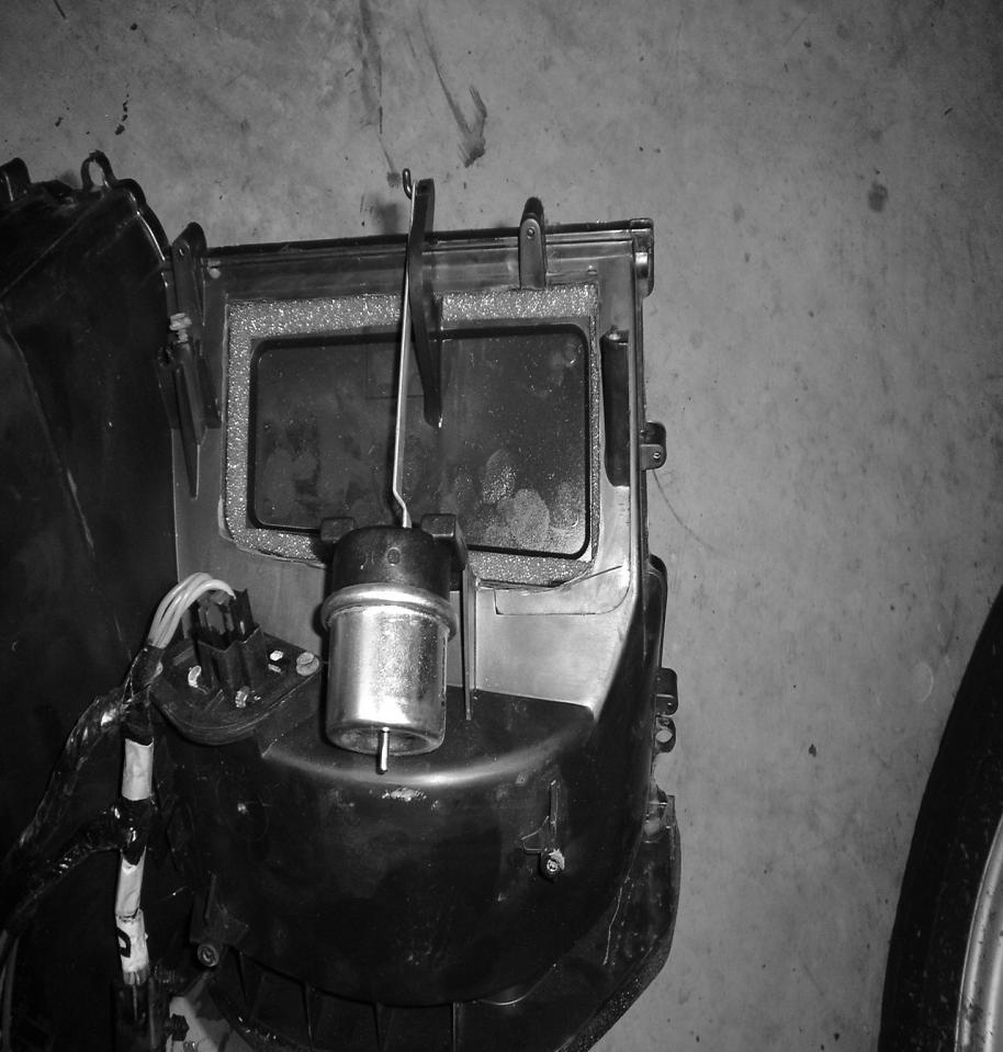
14 STEP NINE Separating the Evaporator case 1. Put the case on a table or bench for easier working conditions. Remove the 15 screws holding the case halves together, remove the two clips holding the case together, and the three screws securing blower motor to the case. 2. Remove the firewall gasket at the blower motor and heater core tubes. Remove the blower motor 3. Separate the evaporator halves. 4. Remove the air inlet cover on the bottom of case, four screws Remove Two clips Figure 9.1 Remove Four screws Securing cover Figure 9.2


15 STEP TEN Installing the Fresh Air door 1. Cut the opening in the case for the door. This can be done with a sharp razor knife by making four passes, or by a cut of wheel or plastic saw. 2. Install the door into the opening 3. Install the vacuum actuator 4. Hook the actuator to the door 5. Mount the actuator on the mounting clamp Figure 10.1 Figure 10.2

16 Figure 10.3 Figure 10.4


17 STEP ELEVEN Installing Evaporator 1. Place the evaporator into the case. Make sure the foam is attached. 2. Set the top half of the plenum back on 3. Insert and tighten the fifteen screws, and two clips 4. Install the blower motor, make sure the foam is in place 5. Install the green vacuum line from plug to actuator, use the vacuum line included to make the connection 6. Install the air inlet cover (four screws, see figure 9.2) 7. MAKE SURE THE HEATER DOOR AND BLEND DOOR MOVE FREELY. Figure 11.1 Green tube 8. See CD for color picture Supplied vacuum tube Figure 11.2


18 STEP TWELVE Attaching Rubber Grommet 1. There is a rubber grommet that sits on the evaporator and heater hose lines. You will need to cut two holes in the grommet and place over the lines. 2. Remove caps over evaporator outlets 3. Push the rubber up against the evaporator tubes, remove and mark with a pen or marker where the lines sit. 4. Take a razor or a round pipe and cut out the two holes. If you use a pipe, place the grommet over a piece of wood and hit the pipe with a hammer. The holes do not need to be larger then ¼. 5. Remove the support brace over the evaporator tubes, with the brace removed you can slide the grommet over the four tubes, place the caps back on the evaporator 6. Pull the vacuum tube through the grommet 7. Now you can reinstall the evaporator case into the vehicle. Follow the directions if needed. Figure 12.1 Figure 12.2


19 Figure 12.3 Figure When reattaching the outside nuts to the studs leave two off, the two above the drain line.


20 STEP THIRTEEN Under Hood Hook up 1. Now that the Inside is back together we can hook up the rest of the parts under the hood. Starts by making sure all the nuts are attached on the outside of the firewall, except for the two above the drain 2. Hook up the Vacuum line, and heater hoses 3. Attach the flat bracket to the two studs that do not have the nuts on them. Be sure the vacuum line does not get stuck between the bracket and firewall 4. Install the round strap for the accumulator drier. Do not tighten 5. Install the accumulator to the strap, and push the fittings from the accumulator to the fitting on the evaporator (large to large fitting) Be sure to PUSH HARD, they need to click 6. Tighten the screw on the strap of accumulator to secure it 7. Plug the accumulator switch to the switch located on the firewall wiring harness Figure 13.1 Figure 13.2

21 Figure 13.3 Figure For more color pictures please see the CD

22 STEP FOURTEEN Attaching the Hoses 1. Place the two flat gasket washers on the hose manifold that connects to the compressor 2. Place the hose manifold on the compressor and tighten 3. Make sure O-rings are put on all fittings connections, if the fittings are hard to push on, dab a little pag oil on the o-rings. 4. Attach smaller line from the compressor to the condenser, PUSH HARD, but be sure to support the condenser tube, DON T BEND IT 5. Connect the plug to the switch located on the Manifold. The plug should be close to the compressor plug near the intake /exhaust manifolds 6. Connect the Liquid line to the evaporator and Condenser. BE SURE THEY CLICK, BE SURE NOT TO BEND THE TUBE ON THE CONDENSER 7. Tie strap the liquid line to the inner fender well, not tight just to keep it from vibrating or rubbing 8. Be sure the Accumulator tube is not hitting the hose manifold tube 9. Reinstall the Air Cleaner Tube (fig on cd) Figure 14.1 Figure 14.2


23 Figure 14.3 Figure More color pictures on the CD
 Figure 15.1 3. Insert an ATM MINI 20 amp fuse into panel.")
24 STEP FIFTEEN Finishing Up 1. Put antifreeze back into the radiator. You may have to start the vehicle to get all the fluid back into the system. 2. Install the a/c relay into the fuse box, located under the hood on passenger side) Figure Insert an ATM MINI 20 amp fuse into panel. If it is already in its place disregard, the fuse location is F Install the battery and hook up the cables 5. Evacuate the a/c system for at least 45 minutes 6. Hook up the Compressor plug. The following page is a supplement to explain the compressor wire hookup. 7. Charge the system with 1.50 lbs of R134a Refrigerant. DO NOT ADD OIL, DYE, SEALERS, OR ANY ALTERNATIVE REFRIGERANTS. 8. Apply the sticker under the hood, and then write in the exact amount of freon used. The system is designed for R134a; you will get the best performance by using it. Insert Fuse Insert relay Figure 15.1


25 15.6 Compressor plug wiring The compressor that is included with our kit uses a clutch coil that is grounded through the compressor. The factory Jeep harness uses a ground in the wiring system. The compressor has a single wire (red or black) and the Jeep plug has two wires (blue or green and black). The plug on the factory harness has to be removed and rewired to fit the compressor with the a/c kit. The blue or green wire plugs into the wire on the compressor, a new connector will need to be used. The black wire is to be grounded. There is a small phillips head screw on the compressor, the screw is holding down the wire from the coil. Use the screw and hold down to ground the black wire. Attach a round loop connector to the wire and place the wire under the phillips head screw. Reattach the screw to the compressor, be sure the wire is held down with the hold down. Factory compressor wire plug High low pressure switch plug, attaches to hose manifold. BLUE BLACK WIRE WIRE
Jeep Wrangler TJ. Complete Air Conditioning System. Slide Control Head. Installation instructions
 WWW.JEEPAIR.COM 1996-1998 Jeep Wrangler TJ Complete Air Conditioning System Slide Control Head Installation instructions Kit Information After 1994 every vehicle was designed for R134a refrigerant. The
Jeep Wrangler TJ 4.0 LITER Installation instructions
 www.jeepair.com 2002-2004 Jeep Wrangler TJ 4.0 LITER Installation instructions Kit Information These directions are for 2002-2006 model Jeep Wranglers. After 1994 every vehicle was designed for R134a refrigerant.
Jeep Wrangler TJ 4.0 LITER Installation instructions
 www.jeepair.com 2000-2001 Jeep Wrangler TJ 4.0 LITER Installation instructions Important information about your system, and warranty DO NOT ADD ANY OIL TO ANY PART OF THE SYSTEM. DO NOT USE THE SIGHT GLASS
Important information about your new a/c system. Please read the following directions prior to installing this a/c system.
 PAGE 1 Important information about your new a/c system. Please read the following directions prior to installing this a/c system. PN s: CK-7586258, CK-758642, CK-7586304, CK7586SBC, CK-7486NC Jeep CJ Series
1. Disconnect the battery. This is important! This will prevent air bag deployment.
 PARTS PACKING LIST Evaporator assembly Drain tube Plastic air plug Hardware package 11040 3601 W. Clarendon Phoenix, Arizona 85019 (602) 233-0090 800-648-4475 www.ackits.com 2003-4 Jeep Wrangler EVAPORATOR
Chevrolet Truck Install Instructions. This kit is designed for the Chevrolet or GMC trucks without factory air conditioning.
 1967-1972 Chevrolet Truck Install Instructions This kit is designed for the 1967-1972 Chevrolet or GMC trucks without factory air conditioning. Glove box Heater box Heater box firewall cover Controls and
Procharger Stage II Intercooled Supercharger System (11-14 GT)
") Procharger Stage II Intercooled Supercharger System (11-14 GT) Installation Time: Approximately one day. Installed on 2012 Mustang GT 5.0/Manual Required Tools 3/8 Socket Set (Standard and Metric) 1/2
Procharger Stage II Intercooled Supercharger System (11-14 GT) Installation Time: Approximately one day. Installed on 2012 Mustang GT 5.0/Manual Required Tools 3/8 Socket Set (Standard and Metric) 1/2
1963 GEN IV SUREFIT VINTAGE AIR CONDITIONING INSTALLATION
 by Randy Irwin 1963 GEN IV SUREFIT VINTAGE AIR CONDITIONING INSTALLATION Randy Irwin - Technical Writer Randy has been involved in the Chevy parts business for over 30 years. He is a wizard at creating,
PERFECT FIT SERIES IN-DASH HEAT/ COOL/ DEFROST MUSTANG
 specializing in AIR CONDITIONING, PARTS AND SYSTEMS for your classic vehicle PERFECT FIT SERIES IN-DASH HEAT/ COOL/ DEFROST 1969-70 MUSTANG CONTROL & OPERATING INSTRUCTIONS The controls on your new Perfect
INSTALLATION INSTRUCTIONS
 INSTALLATION INSTRUCTIONS Accessory Application Publications No. AIR CONDITIONER CIVIC 2- AND 4-DOOR AII 24158 Issue Date SEP 2002 What s New The installation instructions for the 2003 Civic A/C are the
PERFECT FIT IN-DASH HEAT/ COOL/ DEFROST FORD FAIRLANE & CROWN VICTORIA
 PERFECT FIT IN-DASH HEAT/ COOL/ DEFROST 1955-56 FORD FAIRLANE & CROWN VICTORIA CONTROL & OPERATING INSTRUCTIONS The controls on your new Perfect Fit system, offer complete comfort capabilities in virtually
PERFECT FIT SERIES IN-DASH HEAT/ COOL/ DEFROST 1969 CHEVROLET CAMARO/ FIREBIRD NOTE: INSTRUCTIONS DEPICT CAMARO
 specializing in AIR CONDITIONING, PARTS AND SYSTEMS for your classic vehicle PERFECT FIT SERIES IN-DASH HEAT/ COOL/ DEFROST 1969 CHEVROLET CAMARO/ FIREBIRD NOTE: INSTRUCTIONS DEPICT CAMARO CONTROL & OPERATING
& 76 CHEVROLET NOVA HEATER ONLY
 specializing in AIR CONDITIONING, PARTS AND SYSTEMS for your classic hi l PERFECT FIT IN-DASH HEAT/ COOL/ DEFROST 1969-74 & 76 CHEVROLET NOVA HEATER ONLY CONTROL & OPERATING INSTRUCTIONS The controls on
1988 Chrysler LEBARON
 1988 Chrysler LEBARON Submodel: Engine Type: L4 Liters: 2.5 Fuel Delivery: FI Fuel: GAS CAUTION When draining the coolant, keep in mind that cats and dogs are attracted by the ethylene glycol antifreeze,
Installation Instructions for TJ Jeep s Fiberglass Replacement Bodies and Parts
 Installation Instructions for 1997-2006 TJ Jeep s Fiberglass Replacement Bodies and Parts Getting started: We recommend that you take pictures as you dismantle your Jeep. These pictures will help you when
FACTORY AIR CONVERSION HEAT/ COOL/ DEFROST CHEVROLET CHEVELLE
 specializing in AIR CONDITIONING, PARTS AND SYSTEMS for your classic vehicle FACTORY AIR CONVERSION HEAT/ COOL/ DEFROST 1970-72 CHEVROLET CHEVELLE CONTROL & OPERATING INSTRUCTIONS The controls on your
RetroAir JAGUAR XKE S1-3.8 LHD FULL KIT CONTENTS:
 RetroAir JAGUAR XKE S1-3.8 LHD FULL KIT 2-12-2011 CONTENTS: 1- Custom Design Evaporator Case &Core Assembly 1- Universal Bracket (installed) Evaporator Pak includes: 2-Custom Brackets; 2-1-¼ Grommets;
97-02 JEEP TJ BODY LIFT KIT INSTRUCTIONS
 92RC60500 97-02 JEEP TJ BODY LIFT KIT INSTRUCTIONS Congratulations on your purchase of a new Rough Country 2 /3 Body Lift. We are committed to providing you with the best product available for the best
BMW X-5 Evaporator Removal
 BMW X-5 Evaporator Removal Intro: The following instructions will help you in replacing the Air Conditioning Evaporator in a BMW X-5. Following these instructions is at your own risk and the author assumes
JEEP WRANGLER (TJ), UNLIMITED (TJL), RUBICON MODELS BODY LIFT KIT INSTALLATION INSTRUCTIONS KIT# KIT# 973
, UNLIMITED (TJL), RUBICON MODELS BODY LIFT KIT INSTALLATION INSTRUCTIONS KIT# KIT# 973") JEEP WRANGLER (TJ), UNLIMITED (TJL), RUBICON MODELS BODY LIFT KIT INSTALLATION INSTRUCTIONS 1997-2006 2 KIT# 972 3 KIT# 973 WARNING Installation of a Performance Automotive Group body lift will change
JEEP WRANGLER (TJ), UNLIMITED (TJL), RUBICON MODELS BODY LIFT KIT INSTALLATION INSTRUCTIONS 1997-2006 2 KIT# 972 3 KIT# 973 WARNING Installation of a Performance Automotive Group body lift will change
INSTALLATION INSTRUCTIONS FOR COZY CAB A-1 AIR CONDITIONING KIT
 INSTALLATION INSTRUCTIONS FOR COZY CAB A-1 AIR CONDITIONING KIT 05-11 INSTALLATION INSTRUCTIONS A-12235 Air Conditioner Kit Cab set up instructions; This air conditioning kit is designed to be used with
1969 CAMARO VCZ-A
 969 CAMARO w/o FACTORY AIR 55070-VCZ-A 8865 GOLL ST. - SAN ANTONIO, TX. - 78266 ph.20-654-77 - fax 20-654-33 905070-VCZ-A /22/05, 69 CAMARO w/o FAC. AIR INSTRUCTIONS PG OF 20 969 CAMARO w/o FACTORY AIR
CHEVROLET CORVETTE
 Suggested Installation Instructions for: 658-133 and 658-134 1968-1976 Air Conditioning Retro-Fit System 1968-76 CHEVROLET CORVETTE CONTROL & OPERATING INSTRUCTIONS The controls on your new Perfect Fit
ARTICLE BEGINNING * PLEASE READ THIS FIRST * DESCRIPTION OPERATION ATC COMPUTER BLEND-AIR DOOR ACTUATOR CONTROL PANEL
 A/C-HEATER SYSTEM - AUTOMATIC Article Text 1989 Chrysler LeBaron Sedan For m m m m m Copyright 1998 Mitchell Repair Information Company, LLC Thursday, July 03, 2003 10:15AM ARTICLE BEGINNING 1989 AUTOMATIC
JEEP WRANGLER, RUBICON, UNLIMITED (TJ & TJL) 1 BODY LIFT KIT INSTALLATION INSTRUCTIONS KIT# 951
 1 BODY LIFT KIT INSTALLATION INSTRUCTIONS KIT# 951") 3651 N Highway 89 Chino Valley, AZ 86323 (928) 636-7080 www.p-a-g.net JEEP WRANGLER, RUBICON, UNLIMITED (TJ & TJL) 1 BODY LIFT KIT INSTALLATION INSTRUCTIONS 1997-2006 KIT# 951 Installation of a Performance
3651 N Highway 89 Chino Valley, AZ 86323 (928) 636-7080 www.p-a-g.net JEEP WRANGLER, RUBICON, UNLIMITED (TJ & TJL) 1 BODY LIFT KIT INSTALLATION INSTRUCTIONS 1997-2006 KIT# 951 Installation of a Performance
I. Before starting installation
 5. Park the vehicle on a clean, dry, flat, level surface and block the tires so the vehicle cannot roll in either direction. A. Disconnect battery cables 1. Disconnect the negative cable first, then the
A/C SYSTEM SPECIFICATIONS
 A/C SYSTEM SPECIFICATIONS A/C-HEATER SYSTEM - MANUAL 1997 Manual A/C-Heater System WARNING: To avoid injury from accidental air bag deployment, read and follow all SERVICE PRECAUTIONS and DISABLING & ACTIVATING
PRODUCT: Install Instructions, MV-1 C/O Std, With Aux Fan RELEASE DATE: 2/28/14 REVISION DATE: 9/30/2014 PART NUMBER: Rev C
 Parts List (1) 01 000 027 Switch, 4 Position Blower (1) 04 000 007 Hose, 1/2 ID Drain, 6 (1) 01 000 087 Harn, Resistor (1) 04 000 078 Tube, Convo 1/2 x 24 (2) 01 000 136 Relay, 40 Amp (1) 04 000 015 Hose,
TOYOTA TUNDRA 3 BODY LIFT INSTALLATION INSTRUCTIONS 2014 KIT# 5643
 3651 N Highway 89 Chino Valley, AZ 86323 (928) 636-7080 www.p-a-g.net TOYOTA TUNDRA 3 BODY LIFT INSTALLATION INSTRUCTIONS 2014 KIT# 5643 Installation of a Performance Automotive Group body lift kit will
WPS-104 Heater Installation Instructions For 500EFI, 700 XP, & Crew Applications
 WPS-104 Heater Installation Instructions For 500EFI, 700 XP, & Crew Applications ORDER OF INSTALLATION FOR A COMPLETE ENCLOSURE OF A RANGERWARE WPS (Weather Protection System) IS AS FOLLOWS: 1. Heater
Installation Instructions
 2011-2013 LML DURAMAX COMPOUND-ADD 2011-2015 LML A Duramax TURBO KIT Add INSTALL A Turbo INSTRUCTIONS Compound Kit Installation Instructions 1-800-955-0476 - www.industrialinjection.com - info@industrialinjection.com
Rzr Heater System Part #
 Rzr Heater System Part # 2878135 NOTE: This heater unit installs below the center of the dash. If you have a radio mount kit (Polaris Part # 2876897) you may need to cut the top front corner off the mount
DODGE DAKOTA 3 BODY LIFT INSTALLATION INSTRUCTIONS KIT # 60153
 DODGE DAKOTA 3 BODY LIFT INSTALLATION INSTRUCTIONS 2003-04 KIT # 60153 Installation of a Performance Automotive Group body lift kit will change the vehicle s center of gravity and handling characteristics
A/C-HEATER SYSTEM - AUTOMATIC
 A/C-HEATER SYSTEM - AUTOMATIC 1993 Toyota Celica 1993 Automatic A/C-Heater Systems Celica SPECIFICATIONS SPECIFICATIONS TABLE Application Specification Compressor Type 1.6L... Nippondenso 10PA15C 10-Cyl.
05-08 GT. Hellion Power Systems Mustang Kit Instructions
 Hellion Power Systems 05-08 Mustang Kit Instructions 1. Disconnect Battery 2. Drain Radiator, keep fluid for re-installation. 3. Remove air box and inlethoses. 6. Next, underneath, punch oil pan for turbo
Installation Instructions and Suggestions For Jeep YJ Fiberglass Replacement Bodies
 Installation Instructions and Suggestions For Jeep YJ Fiberglass Replacement Bodies Getting started with the removal of your existing Jeep body. Trust nothing to memory; take photos of everything at different
INSTALLATION INSTRUCTIONS 97 FORD EXPEDITION
 INSTALLATION INSTRUCTIONS 97 FORD EXPEDITION 1. Read the instructions completely and carefully before you begin. Check the kit for proper contents (refer to the part s list and the picture diagrams). Before
Subaru Front Mount Intercooler Kit STI Subaru Front Mount Intercooler Kit STI
 Subaru Front Mount Intercooler Kit STI 2008-2014 715500 Subaru Front Mount Intercooler Kit STI 2008-2014 Congratulations on your purchase of the Subaru Front Mount Intercooler Kit STI 2008-2014. The following
Ford F-100 Evaporator Kit (751153)
") an ISO 9001:2015 Registered Company 1968-72 Ford F-100 Evaporator Kit (751153) 18865 Goll St. San Antonio, TX 78266 Phone: 800-862-6658 Sales: sales@vintageair.com Tech Support: tech@vintageair.com www.vintageair.com
an ISO 9001:2015 Registered Company 1968-72 Ford F-100 Evaporator Kit (751153) 18865 Goll St. San Antonio, TX 78266 Phone: 800-862-6658 Sales: sales@vintageair.com Tech Support: tech@vintageair.com www.vintageair.com
MANUAL CONTROL / SEMIAUTO TEMPERATURE CONTROL HEATING, VENTILATION AND AIR CONDITIONING SYSTEM
 SECTION 7C MANUAL CONTROL / SEMIAUTO TEMPERATURE CONTROL HEATING, VENTILATION AND AIR CONDITIONING SYSTEM CAUTION: Disconnect the negative battery cable before removing or installing any electrical unit
BLACKBIRD INSTALLATION SUPPLEMENT
 BLACKBIRD INSTALLATION SUPPLEMENT FOR 2008-105 FORD 6.4 LITER DIESEL F-SERIES VERSION 3/10 Parts Blackbird Wiring Manual Installation Supplement 6.4 liter Diesel Owner s Manual Includes Warrantee Registration
 Page 1 of 6 Section 03-01C: Engine, 7.5L MFI 1996 Bronco/F-Series Workshop Manual IN-VEHICLE SERVICE Procedure revision date: 06/19/2000 Cylinder Heads Removal SPECIAL SERVICE TOOL(S) REQUIRED Description
A/C-HEATER SYSTEM - AUTOMATIC
 A/C-HEATER SYSTEM - AUTOMATIC 1988 Toyota Celica 1988 Automatic A/C-Heater Systems Celica * PLEASE READ THIS FIRST * CAUTION: When discharging air conditioning system, use only approved refrigerant recovery/recycling
ENGINE ASSEMBLY. COMPONENTS (Part 1)
") 1 of 32 ENGINE ASSEMBLY COMPONENTS (Part 1) 2 of 32 COMPONENTS (Part 2) 3 of 32 COMPONENTS (Part 3) 4 of 32 COMPONENTS (Part 4) 5 of 32 COMPONENTS (Part 5) 6 of 32 COMPONENTS (Part 6) 7 of 32 COMPONENTS
1 of 32 ENGINE ASSEMBLY COMPONENTS (Part 1) 2 of 32 COMPONENTS (Part 2) 3 of 32 COMPONENTS (Part 3) 4 of 32 COMPONENTS (Part 4) 5 of 32 COMPONENTS (Part 5) 6 of 32 COMPONENTS (Part 6) 7 of 32 COMPONENTS
2003 Explorer Sport/Sport-Trac Workshop Manual. 7. Disconnect the vacuum harness connector. Remove the nut.
 7. Disconnect the vacuum harness connector. Remove the nut. 8. Remove two nuts, one bolt, and the A/C evaporator housing (19850). Remove the nut located at the bottom of the A/C evaporator housing first.
DESCRIPTION & OPERATION
 DESCRIPTION & OPERATION HEATER SYSTEM 1997 Heater System WARNING: To avoid injury from accidental air bag deployment, read and follow all SERVICE PRECAUTIONS and DISABLING & ACTIVATING AIR BAG SYSTEM procedures
WPS-104 Heater. Installation Instructions
 WPS-104 Heater Installation Instructions For 2007 vehicles see page 15 WPS 104 HEATER SYSTEM INSTALLATION INSTRUCTIONS If this is a complete installation of top, windshield and heater system, for ease
Code 0 Description Pic Link # Used Diameter Thread Pitch Length Washer 1 Washer2 Nut size Class Notes F Alternator bracket mounting bolts
 Code 0 Description Pic Link # Used Diameter Thread Pitch Length Washer 1 Washer2 Nut size Class Notes 1 15 1 2F Alternator bracket mounting bolts (Engine Lift Hook) 3 10 1.25 30 split washer flat 4 14mm
A/C-HEATER SYSTEM - AUTOMATIC
 A/C-HEATER SYSTEM - AUTOMATIC 1996 Subaru SVX 1995-96 AUTOMATIC A/C-HEATER SYSTEMS Subaru SVX * PLEASE READ THIS FIRST * WARNING: To avoid injury from accidental air bag deployment, read and carefully
18SP680Rev3 EPA04 MBE 4000 Car Hauler Low Pressure Fuel Lines
 8SP680Rev3 EPA04 MBE 4000 Car Hauler Low Pressure Fuel Lines KIT DESCRIPTION These service kits include all necessary parts to replace the low pressure fuel lines between the fuel filter housing and fuel
Installation Manual PERFECT FIT Mustang Factory Air SERIES. Elite DOCUMENT #1-2026FA ClassicAutoAir / 6.11vs1
 PERFECT FIT SERIES Elite Installation Manual 1967-1968 Mustang Factory Air DOCUMENT #1-2026FA 2011 ClassicAutoAir / 6.11vs1 Congratulations... You have just purchased the highest quality, best performing
A/C-HEATER SYSTEM - AUTOMATIC
 A/C-HEATER SYSTEM - AUTOMATIC 1994 Volvo 960 1994 Auto. A/C-Heater System Volvo 960 A/C SYSTEM SPECIFICATIONS AUTOMATIC A/C SYSTEM SPECIFICATIONS TABLE Application Specification Compressor Type... Sanden
This information covers the proper procedure for replacing the Volvo D16F engine in a VT or VNL chassis.
 Volvo Trucks North America Greensboro, NC USA Engine, Replacement DService Bulletin Trucks Date Group No. Page 10.2007 210 139 1(47) Engine, Replacement Volvo D16F VNL, VT W2005773 This information covers
Installation Manual v1.0: MST Turbo Kit ( ) 5.9L Dodge. Please read all instructions before installation.
 5.9L Dodge. Please read all instructions before installation.") Installation Manual v1.0: MST Turbo Kit (2003-2007) 5.9L Dodge Please read all instructions before installation. Figure 1: MST Kit Contents Figure 2: MST Hardware Kit Please make sure all of the components
Installation Manual v1.0: MST Turbo Kit (2003-2007) 5.9L Dodge Please read all instructions before installation. Figure 1: MST Kit Contents Figure 2: MST Hardware Kit Please make sure all of the components
Installation Manual F Body (TPI)
") Installation Manual 1986-87 F ody (TPI) Engine Compartment Upgrade Kit - 22-229 and 22-229D Congratulations... You have just purchased the highest quality, best performing /C system upgrade ever designed
Installation Manual 1986-87 F ody (TPI) Engine Compartment Upgrade Kit - 22-229 and 22-229D Congratulations... You have just purchased the highest quality, best performing /C system upgrade ever designed
Cutlass without Factory Air
 an ISO 9001: 2008 Registered Company 1970-72 Cutlass without Factory Air 561076 18865 Goll St. San Antonio, TX 78266 ph: 210-654-7171 fax: 210-654-3113 901076 REV A 9/17/12, INST 1970-72 CUTLASS wo AC
TABLE OF CONTENTS INTRODUCTION 3. INSTALLATION PROCEDURES Air Conditioner Location 4. A/C Ducting Installation 5
 585474 1 TABLE OF CONTENTS SECTION PAGE INTRODUCTION 3 INSTALLATION PROCEDURES Air Conditioner Location 4 Air Conditioner Mounting 4 A/C Ducting Installation 5 Power Kit Installation (Batteries). 5 Separator...
Installation Manual v1.0: Aurora Plus Turbo Kit ( ) 5.9L Dodge. Please read all instructions before installation.
 5.9L Dodge. Please read all instructions before installation.") Installation Manual v1.0: Aurora Plus - 4000 Turbo Kit (2003-2007) 5.9L Dodge Please read all instructions before installation. Figure 1: Aurora Plus - 4000 Kit Contents 1 Figure 2: Aurora Plus Hardware
Installation Manual v1.0: Aurora Plus - 4000 Turbo Kit (2003-2007) 5.9L Dodge Please read all instructions before installation. Figure 1: Aurora Plus - 4000 Kit Contents 1 Figure 2: Aurora Plus Hardware
1) Remove side panels. Remove clutch cover. Remove windshield by pulling up on the three posts secured into
 Remove side panels. Remove clutch cover. Remove windshield by pulling up on the three posts secured into") UNDER HOOD HEAT ELIMINATOR A.K.A. THE BLOW HOLE by Mountain Tek Application 2013 Model Year SKIDOO XM Kit Contents 1) (1) Fan Tube Assembly 2) (1) Accessory Connect Harness 3) (1) Fan Vent Cover Plate
UNDER HOOD HEAT ELIMINATOR A.K.A. THE BLOW HOLE by Mountain Tek Application 2013 Model Year SKIDOO XM Kit Contents 1) (1) Fan Tube Assembly 2) (1) Accessory Connect Harness 3) (1) Fan Vent Cover Plate
Air Conditioner for M915 A0/A1 Truck
 RD-2-4530-0 Air Conditioner for M915 A0/A1 Truck INSTALLATION INSTRUCTIONS Install refrigerant compressor per instructions provided with compressor mount kit. CAUTION: Edges of sheet metal can be sharp!
CHEVY COLORADO GMC CANYON BODY LIFT INSTALLATION INSTRUCTIONS KIT # 10153
 CHEVY COLORADO GMC CANYON BODY LIFT INSTALLATION INSTRUCTIONS 2004-2005 3 KIT # 10153 Installation of a Performance Automotive Group body lift kit will change the vehicle s center of gravity and handling
PRODUCT USE INFORMATION
 9RC61000 Jeep YJ Body Lift Thank you for choosing Rough Country for all your suspension needs. This body lift fits both manual and Automatic equipped vehicles!!! Refer to last page of this Instruction
Mustang Radiator Conversion DIY. By GearHeadPeter. January 27, 2011
 1964-1966 Mustang Radiator Conversion DIY By GearHeadPeter January 27, 2011 We all know that the radiators in our cars are not the best, especially if you have done any customization to the engine, which
Cutlass with Factory Air
 an ISO 9001: 2008 Registered Company 1968-69 Cutlass with Factory Air 564069 18865 Goll St. San Antonio, TX 78266 ph: 210-654-7171 fax: 210-654-3113 904057 REV B 10/2/12, INST 1968-69 CUTLASS w/ AC EVAP
C40008 & C40009 EXHAUST BRAKES
 EXHAUST BRAKES C40008 & C40009 1995 2003 Ford F250 / F350 7.3 L Powerstroke Diesel with manual transmissions 1995 1998 Ford F250 / F350 7.3 L Powerstroke Diesel with automatic transmission* *Requires the
DewEze Clutch Pump Kit Ford 6.2L Gas, A Pump, Side Port, 2011+
 DewEze Clutch Pump Kit 700512 Ford 6.2L Gas, A Pump, Side Port, 2011+ INSTALLATION INSTRUCTIONS 1. The installation of this kit requires trained decisionmaking concerning clearances, tying components together,
SCION xb PERFORMANCE AIR INTAKE Section I Installation Preparation 2.4L I-4
 Section I Installation Preparation 2.4L I-4 Part Number(s): PTR03-52110 Kit Contents Item # Quantity Description Reqd. 1 1 TRD Inlet Tube 2 1 TRD Upper Air Box with HC Trap 3 1 Hump Hose Coupler 4 1 Hump
2001 Dodge Caravan Sport MANUAL A/C-HEATER SYSTEMS Caravan, Town & Country, & Voyager
 SPECIFICATIONS NOTE: Information for Caravan includes the Grand Caravan. SPECIFICATIONS Application Specification Compressor Type Nippondenso 10S20H Compressor Belt Tension (1) System Oil Capacity (2)
Engine, disassembling and
 Page 1 of 38 13-1 Engine, disassembling and assembling Lock carrier, moving into service position Special tools and equipment 3369 support tool 1 - Bolts 2 - Bolts 3 - Bolts 4 - Bolts 5 - Bore 45 Nm (33
1997 Volvo 850 GLT. Fig. 2: Removing Drive Shaft, Engine Mount Bolt & Torque Arm (5-Cylinder) Courtesy of VOLVO CARS OF NORTH AMERICA.
 Courtesy of VOLVO CARS OF NORTH AMERICA.") Fig. 2: Removing Drive Shaft, Engine Mount Bolt & Torque Arm (5-Cylinder) 4. Remove front exhaust pipe nuts and springs. Remove front exhaust pipe bolts. Disconnect speedometer. Remove engine mounting
Fig. 2: Removing Drive Shaft, Engine Mount Bolt & Torque Arm (5-Cylinder) 4. Remove front exhaust pipe nuts and springs. Remove front exhaust pipe bolts. Disconnect speedometer. Remove engine mounting
Depress each tab as you pull the bezel off. The bezels are tight. L.H. shown.
 2013-2014 Ford Mustang V6 & Boss 302 Lower Valance Fog Light Kit Parts List: Quantity: Tool List: Fog light & bulb with bracket 2 Flat head & Phillips screwdriver Black bezels 2 Ratchet & Socket set OR
JEEP WRANGLER INSTALLATION INSTRUCTIONS KIT SUM
 1986-1995 JEEP WRANGLER INSTALLATION INSTRUCTIONS KIT SUM-7893300 Installation of a body lift will change the center of gravity and the handling characteristics of the vehicle. Because of the higher center
INSTALLATION INSTRUCTIONS DODGE DAKOTA 2 KIT # 682 (2WD), 692 (4WD) 3 KIT # 683 (2WD), 693 (4WD)
, 692 (4WD) 3 KIT # 683 (2WD), 693 (4WD)") INSTALLATION INSTRUCTIONS 1997-1999 DODGE DAKOTA 2 KIT # 682 (2WD), 692 (4WD) 3 KIT # 683 (2WD), 693 (4WD) Installation of a Performance Accessories body lift kit will change the vehicle s center of gravity
INSTALLATION INSTRUCTIONS 1997-1999 DODGE DAKOTA 2 KIT # 682 (2WD), 692 (4WD) 3 KIT # 683 (2WD), 693 (4WD) Installation of a Performance Accessories body lift kit will change the vehicle s center of gravity
NISSAN FRONTIER 2 & 4WD AUTOMATIC & MANUAL TRANS. KING & CREW CAB MODELS 3 BODY LIFT KIT INSTALLATION INSTRUCTIONS KIT# 40083
 3651 N Highway 89 Chino Valley, AZ 86323 (928) 636-7080 www.p-a-g.net NISSAN FRONTIER 2 & 4WD AUTOMATIC & MANUAL TRANS. KING & CREW CAB MODELS 3 BODY LIFT KIT INSTALLATION INSTRUCTIONS 2005-2011 KIT# 40083
INSTALLATION INSTRUCTIONS
 INSTALLATION INSTRUCTIONS Part# 22-7810 Add On Kit for Your ADS System Contents: Complete Install Kit for Your ARB CKMTA12V Compressor For the most up-to-date instructions please visit www.updownair.com
WOC-364 Installation Instructions Ranger XP Heater System
 WOC-364 Installation Instructions Ranger 2011-12 XP Heater System Order of installation for a Complete Enclosure Always install the Heater System first if possible NOTE: If installing the Heater System
2013 Mustang Workshop Manual
 32. Attach the wiring harness retainers to the LH side of the oil pan and the front oil pan stud bolts and install the 2 nuts. Tighten to 8 Nm (71 lb-in). 33. Position the underbody shield and install
DewEze Clutch Pump Kit Ford 6.2L Gas, A Pump, Side Port, INSTALLATION INSTRUCTIONS 1. The installation of this kit requires trained decis
 DewEze Clutch Pump Kit 700564 Ford 6.2L Gas, A Pump, Side Port, 2014+ INSTALLATION INSTRUCTIONS 1. The installation of this kit requires trained decisionmaking concerning clearances, tying components together,
1995 Chrysler Cirrus 2.5L MFI 6cyl Repair Guides Charging System Alternator Auto...
 Page 1 of 9 SAVE 20% + GET A $10 GIFT CARD ON ONLINE SHIP-TO-HOME ORDERS OF $100 OR MORE. Use Code: 20TUNE10 See Details Chrysler Cirrus/Stratus/Sebring/Avenger/Breeze 1995-1998 TESTING REMOVAL & INSTALLATION
Installation Instructions for Lingenfelter GM 2500 Suburban & Yukon XL Auxiliary Fan System (with AC clutch controlled fan output)
") Installation Instructions for Lingenfelter 2007-2013 GM 2500 Suburban & Yukon XL Auxiliary Fan System (with AC clutch controlled fan output) PN L300080607 Revision - 1.1 Lingenfelter Performance Engineering
Installation Instructions for Lingenfelter 2007-2013 GM 2500 Suburban & Yukon XL Auxiliary Fan System (with AC clutch controlled fan output) PN L300080607 Revision - 1.1 Lingenfelter Performance Engineering
2017+ L5P Duramax 3 ½ Down Pipe & EGR Fix Kit
 2017+ L5P Duramax 3 ½ Down Pipe & EGR Fix Kit Covers installation of PN s: WCF100630, WCF100829 Note: This Kit is for off road competition use only! Off Road Competition Use Tuning & Exhaust System is
TSB #: 53 Date: 2/11/2011 HOLDEN (DELPHI) VARIABLE STROKE COMPRESSOR DIAGNOSIS STEP ACTION RESULT YES NO
 VARIABLE STROKE COMPRESSOR DIAGNOSIS STEP ACTION RESULT YES NO") HOLDEN (DELPHI) VARIABLE STROKE COMPRESSOR DIAGSIS TSB #: 53 Date: 2/11/2011 Initial Once Read: Even though the Holden variable stroke compressor manufactured by Delphi has been in the Australian market
HOLDEN (DELPHI) VARIABLE STROKE COMPRESSOR DIAGSIS TSB #: 53 Date: 2/11/2011 Initial Once Read: Even though the Holden variable stroke compressor manufactured by Delphi has been in the Australian market
1 of 12 10/5/2015 8:11 AM
 1 of 12 10/5/2015 8:11 AM REMOVAL 1. Perform the fuel pressure release procedure See: Fuel Pressure Release > Procedures > Fuel System Pressure Release Procedure. 2. Recover the refrigerant from the refrigerant
file://c:\program Files\tsocache\OFFICE_5164\SYA~us~en~file=SYA1C003.htm~gen~re...
 Page 1 of 26 SECTION 501-12: Instrument Panel and Console 2000 Crown Victoria/Grand Marquis Workshop Manual REMOVAL AND INSTALLATION Procedure revision date: 06/21/1999 Instrument Panel Removal CAUTION:
Huron Speed Products Twin Turbo Install Gen 2 CTS-V (09-15)
") Huron Speed Products Twin Turbo Install Gen 2 CTS-V (09-15) The following install guide is simply that, a guide to help you with installation. It is by no means the exact method to perform installation,
Huron Speed Products Twin Turbo Install Gen 2 CTS-V (09-15) The following install guide is simply that, a guide to help you with installation. It is by no means the exact method to perform installation,
BLACKBIRD INSTALLATION SUPPLEMENT
 BLACKBIRD INSTALLATION SUPPLEMENT FOR 2003-7 FORD 6.0 LITER DIESEL SINGLE ALTERNATOR F-350, F-450, F-550, EXCURSION VERSION 7-07 Parts Description Blackbird Wiring Manual Installation Supplement 6.0 Liter
Step 6: Remove and save the MAP sensor for later use. Step 7: Remove the passenger side intercooler pipe and the EGR intake manifold.
 LBZ Twin kit Install Step 1: Disconnect both batteries. Step 2: Drain coolant and oil also remove passenger side inner fender. Step 3: Remove intake box and piping. (Remove and save the MAF sensor in the
1996 Aerostar/Ranger/Explorer
 Page 1 of 11 Section 03-01B: Engine, 3.0L V-6 IN-VEHICLE SERVICE 1996 Aerostar and Ranger Vehicles Workshop Manual Water Pump SPECIAL SERVICE TOOL(S) REQUIRED Description Tool Number Fan Clutch Holding
INSTALLATION INSTRUCTIONS ELEVATION FRONT BUMPER DODGE RAM
 INSTALLATION INSTRUCTIONS PARTS LIST: 1 Elevation Bumper Assembly 24 12mm x 37mm OD x 3mm Flat Washers 2 Frame Mounting Brackets 12 12mm Nylon Lock Nuts 8 12-1.75mm x 50mm Hex Bolts 2 License Plate Mounting
Installation Manual Camaro
 Installation Manual 1989-1992 Camaro Engine Compartment Upgrade Kit - 22-230 & 22-230D Series Congratulations... You have just purchased the highest quality, best performing /C system upgrade ever designed
M62 Alternator Removal / Replacement (Water Cooled)
") M62 Alternator Removal / Replacement (Water Cooled) Pre-Steps 1. Disconnect Battery Positive lead 2. Charge Your Battery with battery charger to full charge (So you new alternator wont have to work as
M62 Alternator Removal / Replacement (Water Cooled) Pre-Steps 1. Disconnect Battery Positive lead 2. Charge Your Battery with battery charger to full charge (So you new alternator wont have to work as
R-8230 Underdash Heater/Air Conditioner Unit
 INTERNATIONAL R-8230 Underdash Heater/Air Conditioner Unit NAVISTAR INTERNATIONAL S, 4000, 7000, and 8000 SERIES TRUCKS, 1983 1994 The R-8230 exceeds the performance of the original system and has styling
TOYOTA FJ CRUISER / 4RUNNER COLD AIR INTAKE Section I Installation Preparation. 4.0L V6 (1GR) Roller Rocker Part Number(s): PTR
 Roller Rocker Part Number(s): PTR") Section I Installation Preparation Part Number(s): PTR03-89100 Kit Contents Item # Quantity Reqd. Description 1 1 Air Filter (P/N: PTR43-00083) 2 1 Upper Air Box 3 1 Lower Air Box 4 1 Hump Coupler 5 1
Section I Installation Preparation Part Number(s): PTR03-89100 Kit Contents Item # Quantity Reqd. Description 1 1 Air Filter (P/N: PTR43-00083) 2 1 Upper Air Box 3 1 Lower Air Box 4 1 Hump Coupler 5 1
2006 Honda Civic SI Supercharger Kit Installation Instruction Kit #
 2006 Honda Civic SI Supercharger Kit Installation Instruction Kit #350-091 3239 MONIER CIRCLE, STE.5 RANCHO CORDOVA, CA 95742 916.635.4550 FAX 916.635.4632 www.ct-engineering.com INS-157 VERSION: 3.25.2009
NISSAN TITAN 3 BODY LIFT INSTALLATION INSTRUCTIONS KIT # 40053
 3651 N Highway 89 Chino Valley, AZ 86323 (928) 636-7080 NISSAN TITAN 3 BODY LIFT INSTALLATION INSTRUCTIONS 2004-2009 KIT # 40053 Installation of a Performance Automotive Group body lift kit will change
CHEVY AVALANCHE 1/2-TON ONLY 3 BODY LIFT KIT INSTALLATION INSTRUCTIONS KIT# 10173
 3651 N Highway 89 Chino Valley, AZ 86323 (928) 636-7080 www.p-a-g.net CHEVY AVALANCHE 1/2-TON ONLY 3 BODY LIFT KIT INSTALLATION INSTRUCTIONS 2003-2005 KIT# 10173 Installation of a Performance Automotive
V1 Truck Manifold Turbo Kit for F-body
 V1 Truck Manifold Turbo Kit for 98-02 F-body Prep: -Remove all A/C Components, Alternator and brackets, tensioner, front bumper, front bumper foam, and front bumper support. Remove radiator and cooling
INSTALLATION MANUAL
 315000 INSTALLATION MANUAL EGR & Cooler Race Kit for 2015+ 6.7L Ford Powerstroke WARNING ONLY install this kit if you are using a tuner that disables the EGR sensors & circuit system. Any product that
INSTALLATION INSTRUCTIONS
 INSTALLATION INSTRUCTIONS Accessory Application Publications No. 2003 ELEMENT AII 24318 Issue Date DEC 2002 PARTS LIST Trailer Hitch Kit P/N 08L92-SCV-100 4 Bolts, 12 x 35 mm Trailer hitch U-bolt 2 Nuts,
Huron Speed Products Twin Turbo Install Gen 2 CTS-V (09-15)
") Huron Speed Products Twin Turbo Install Gen 2 CTS-V (09-15) 1 2 Remove two bolts in trunk cover with 8mm socket. Pull up on cover to remove. Unscrew net tie down on side cover where battery is located
Huron Speed Products Twin Turbo Install Gen 2 CTS-V (09-15) 1 2 Remove two bolts in trunk cover with 8mm socket. Pull up on cover to remove. Unscrew net tie down on side cover where battery is located