9/02 Kwikee Products Co. Inc. Kwikee # Electric Steps. Equipped with a Permanent Magnet Motor
|
|
|
- Lily Newman
- 5 years ago
- Views:
Transcription

 -")


1 Owner's Manual #880 9/02 Kwikee Products Co. Inc. Kwikee # Electric Steps Equipped with a Permanent Magnet Motor (For steps with Control Units , , or and steps without Control Units) Single Steps Double Steps Triple Steps Van Steps 3 Identification Information 4 Introduction 5 Operating the Step 6 Maintenance: Lubrication Cam Stop Adjustment 8 General Service Notes 9 Troubleshooting and Testing Procedures

2 PLEASE NOTE: The 880 Owners Manual shipped with steps prior to October Repair parts listed on this page are no longer the manufacturer s recommended repair procedure. See new Replacement Kits listed on Page 7 of this training.
3
4

5
6

7

8
9
10
 The voltage reading should be approximately 12 volts DC when ignition is on and zero (O) volts when ignition is off.")
 can be connected to the step wiring circuit. Any device connected to the steps wiring can cause the step to malfunction and will void the warranty. 16.")
. NOTE: Be sure to use the terminal with only the white wire. The reading should be a minimum of 12 volts DC.")
 volts, check the step fuse/circuit breaker, all connections, and the condition of the wiring between the battery and the plug, including the ground connection at")
11 15. To check the ignition override system, connect a voltmeter between the yellow wire from the 4-way connector (vehicle half) and the ground terminal on the end of the control unit's green ground wire (see Figure 16 on Page 12.) The voltage reading should be approximately 12 volts DC when ignition is on and zero (O) volts when ignition is off. rf the reading is zero when the ignition is on, check all tenninal connections, wiring, and the vehicle's ignition fuse. NOTE: The step wiring circuit must be independent. No other device (i.e. alarm systems, step well lights, etc.) can be connected to the step wiring circuit. Any device connected to the steps wiring can cause the step to malfunction and will void the warranty. 16. For steps equipped with door switch only operation: Connect the white jumper wire from the vehicle half of the four-way connector and the ground terminal at the end of the control unit's green ground wire (see Figure 17). NOTE: Be sure to use the terminal with only the white wire. The reading should be a minimum of 12 volts DC. lfthe voltage reading is low, there may be a loose or corroded connection at the battery, a low charge level on the battery itself, or a poor ground. If the voltage reading is zero (0) volts, check the step fuse/circuit breaker, all connections, and the condition of the wiring between the battery and the plug, including the ground connection at the chassis. lf you have additional questions or need more assistance, contact K wikee's Service Representative at FIGURE 16: Check ignition override Yellow /" FIGURE 17: Check connector ---- Brown Ground wire: green ground wire must be attached to vehicle chassis; a good ground is needed for proper step operation Ground wire: green ground wire must be attached to vehicle chassis; a good ground is needed for proper step operation Voltmeter should read 12 volts DC/ ignition 'on' 0 volts DC / ignition 'off Owner's Manual #880: Kwikee Electric Steps

12 PLEASE NOTE: At the time of the printing of this Training, 42 Series Steps have not been changed over to the new IMGL and Control Unit. This changed is scheduled to happen mid-year 2005 at which time information relating to the control unit, motor, and gearbox will be updated. Check downloadable documents for updates. If you have a service or repair related question, contact the Kwikee Customer Service Department at

13
14
15
16
17
18
19
20
21
22 4. To check the igrution override system, connect a voltmeter between the yellow wire from the 4-way connector (vehicle half) and the ground terminal on the end of the control unit's green ground wire (see Figure 9.) The voltage reading should be approximately 12 volts DC when igrution is on and zero (0) volts when igrution is off. If the reading is zero when the ignition is on, check all terminal connections, wiring, and the vehicle's ignition fuse. NOTE: The step wiring circuit must be independent. No other device (i.e. alarm systems, step well lights, etc.) can be connected to the step wiring circuit. Any device connected to the steps wiring can cause the step to malfunction and will void the warranty. 5. For steps equipped with door switch only operation: Connect the white jumper wire from the vehicle half of the four-way connector and the ground te1minal at the end of the control unit's green ground wire (see Figure 10). NOTE: Be sure to use the terminal with only the white wire. The reading should be a minimum of 12 volts DC. If the voltage reading is low, there may be a loose or c01roded connection at the battery, a low charge level on the battery itself, or a poor ground. If the voltage reading is zero (0) volts, check the step fuse/circuit breaker, all connections, and the condition of the wiring between the battery and the plug, including the ground connection at the chassis. If you have additional questions or need more assistance, contact Kwikee's Service Representative at
 Connecting the KwikTest unit to the Step (See Figure 1, Page 2) Step 1) Attach the Packard style four-way")
 Attach one of the green wire clips to the negative post of the battery.")
 Set the Control Switch to \"black\" or \"white\" depending on the color of the control unit on the step being tested.")


23 KwikTest Users Manual # Kwikee Products Co., Inc. Kwikee # Rev. 3 KwikTest Users Manual Part # KwikTest Part # (includes 4-way connector) Connecting the KwikTest unit to the Step (See Figure 1, Page 2) Step 1) Attach the Packard style four-way connector from the KwikTest to the four-way connector on the step control unit. Step 2) Connect the red wire clip to the positive post on the battery. Step 3) Attach one of the green wire clips to the negative post of the battery. Attach the other green wire clip to the ring terminal on the end of the 12 gauge green ground wire coming from the step control unit. KwikTest Set Up: For all steps except those with Control Unit # Step 4A) Set the Control Switch to "black" or "white" depending on the color of the control unit on the step being tested. NOTE: On steps fitted with the rubber four-way plug, use the four-way plug/pigtail (included with the KwikTest) to make the connection between the step control unit and the tester. sequence listed. Test 1 Settings Test 2 Settings Test 3 Settings Test 4 Settings Test 5 Settings Test 6 Settings Test 7 Settings Test 8 Settings Test 9 Settings Test 10 Setting Test 11 Settin A. Testing Procedures For all steps except those with Control Unit # Run the following test a minimum of 6 cycles, allowing 3 to 5 seconds between opening and closing the Door Switch to give the control unit internal relays enough time to reset. Door Step Switch Step Function Light ON CLOSED OPEN STAYS GOES STAYS OFF ON IN OUT OUT [g' D D D D D I( D D D D D D lit D D D D [g' D D D [I( lit D D D D D lit D lit D D D D Ill" D D D D [g' D At this point the step should remain extended until one of the following occurs: a) The Door Switch is flipped "close" and the Power Switch is in the "on" position, or b) The Door Switch is flipped "close" and the Ignition Switch is in the "on" position. NOTES: (1) The ignition override will not work until the door is closed. (2) For steps fitted with a white control unit, the 'last-out' feature will be disabled by turning the power switch on and then off (between steps 16 and 17), or if the power switch is "on" when the ignition is turned "off" and is then turned "off" before the door is opened. These sequences will disable the 'last-out' feature and the step will not extend. D D D D D D D

24

25 Maintenance: Lubricate with KwikLube 73

26 74 Maintenance: Adjusting the Cam Stop
27 Maintenance: Manual Retraction of the Step 75

28 76 Door Switches When troubleshooting a coach, you may run into any of these door switches. The important thing to determine is whether the switch is normally open or normally closed. Use the chart below to identify the switch. The current IMGL (integrated motor/gear box/linkage) and Control Unit operates properly with any of the belowed listed NORMALLY OPEN switches.
revised. You can make sure you are looking at the most recent KEEPING SERVICE INFORMATION CURRENT
 1 part 1: WELCOME to the Kwikee Products Service Training. It is our sincere hope that the information you gain from this training will enhance your confidence in and familiarity with the products we manufacture.
Kwikee IMGL Step Control Testing Procedure #82-ST0500
 Kwikee IMGL Step Control Testing Procedure #82-ST0500 TABLE OF CONTENTS Introduction 2 Resources Required 2 General Service Notes 3 Preparation 5 Troubleshooting and Test Procedures 5 Testing the Step
Kwikee # Series Step OWNER'S MANUAL ( )
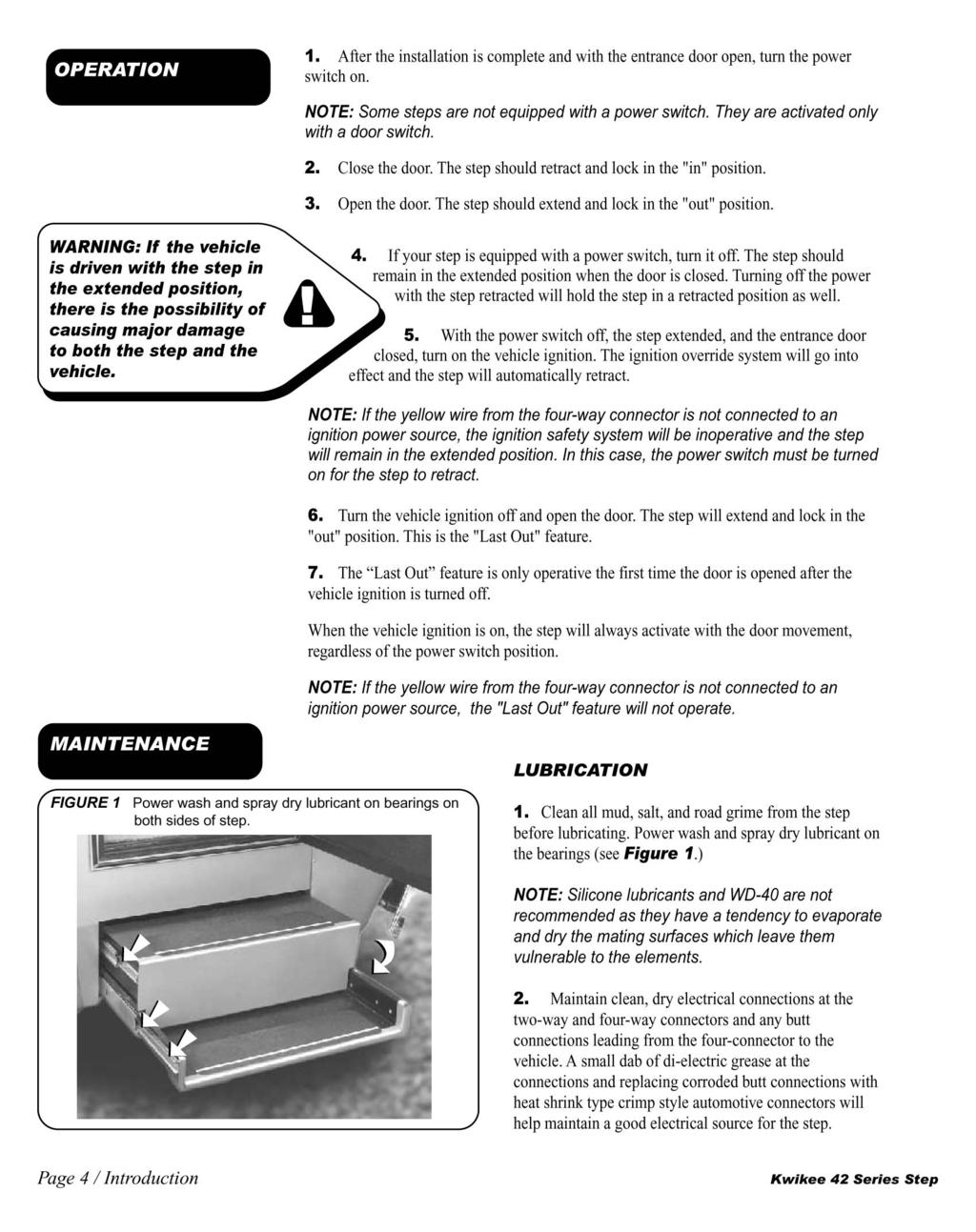
") Kwikee #842 42 Series Step OWNER'S MANUAL (1422258) TABLE OF CONTENTS Safety Information 2 Product Information 3 Step with Control Unit 3 Operation 3 General Service 4 Prior To Operation 4 Adjusting Cam
Kwikee #842 42 Series Step OWNER'S MANUAL (1422258) TABLE OF CONTENTS Safety Information 2 Product Information 3 Step with Control Unit 3 Operation 3 General Service 4 Prior To Operation 4 Adjusting Cam
Kwikee Revolution Step Series
 Kwikee Revolution Step Series OWNER'S MANUAL (3010002262) Rev: 07.26.2018 Kwikee Revolution Step Series Owner's Manual 3010002262 TABLE OF CONTENTS Safety Information 2 Product Information 2 General Service
KWIKEE #888 ELECTRIC STEP. Owner's Manual ( )
") KWIKEE #888 ELECTRIC STEP Owner's Manual (1422279) TABLE OF CONTENTS Safety Information 2 Motor Assembly Identification 3 Product Information 4 Steps With Control Unit 4 Steps Without Control Unit 4 General
KWIKEE #888 ELECTRIC STEP Owner's Manual (1422279) TABLE OF CONTENTS Safety Information 2 Motor Assembly Identification 3 Product Information 4 Steps With Control Unit 4 Steps Without Control Unit 4 General
revised. You can make sure you are looking at the most recent KEEPING SERVICE INFORMATION CURRENT
 1 part 1: WELCOME to the Kwikee Products Service Training. It is our sincere hope that the information you gain from this training will enhance your confidence in and familiarity with the products we manufacture.
42 Series Step. Owner's Manual #842A. Equipped with a Permanent Magnet Motor. Table of Contents
 Owner's Manual #842A 10/05 Kwikee #1422258, Rev. 0A ED 42 Series Step Equipped with a Permanent Magnet Motor D IS C O N TI N U For steps with Control Unit 909510000 and steps without Control Units Table
Kwikee Platinum Series OWNER'S MANUAL
 Kwikee Platinum Series OWNER'S MANUAL TABLE OF CONTENTS Safety Information 2 Product Information 2 General Service Notes 3 Prior To Operation 3 Operation 4 Step with Control Unit 4 Troubleshooting 5 Step
4 7 Series Step Equipped with a
 Owner's Manual 47 Series Step (>Sl(ff Kvllkee ltjot0001164 Rev 0A 4 7 Series Step Equipped with a Permanent Magnet Motor Introduction /\.CAUTION READALL OPERATING INSTRUCTIONS FIRST BEFORE USING YOUR KW
Auto-Level Troubleshooting (Old Platform) Electronic Control- Prior to 2009, Pressure Switch Control panel #s 2057, 2058, 2795, 2795B
 Electronic Control- Prior to 2009, Pressure Switch Control panel #s 2057, 2058, 2795, 2795B") Auto-Level Troubleshooting (Old Platform) Electronic Control- Prior to 2009, Pressure Switch Control panel #s 2057, 2058, 2795, 2795B This guide addresses the troubleshooting of electronic controls used
Auto-Level Troubleshooting (Old Platform) Electronic Control- Prior to 2009, Pressure Switch Control panel #s 2057, 2058, 2795, 2795B This guide addresses the troubleshooting of electronic controls used
Owner's Manual #875. Table of Contents. 2 Step Identification Information. Warranty Information. 2 Introduction. 3 Operating the Step
 wner's Manual #875 9/02 Kwikee Products o. Inc. Kwikee #1422255 E Electric Steps Equipped with a Permanent Magnet Motor and ontrol nit (For steps using control units 9009506000, 909506000, 909507000, or
STANDARD STEP IDENTIFICATION
 Content Table of Contents Page 1-2: Introduction & Step ID Instructions Page 3: Single Step Parts Page 4-5: Double Step Parts Page 6: Page 6: Page 7: Page 8: NOTE Triple Step Parts IMGL Control Box IMGL
Service Manual for Battery Control Center
 Service Manual for Battery Control Center P/N 82 E0071 00 (Ref. 81 1317) June, 1999 Battery Control Box Operation Charging Circuit This function charges the coach battery from the engine alternator while
Embedded Rack Slide-out System
 Embedded Rack Slide-out System SERVICE MANUAL Rev: 02.16.2017 Page 1 Electric Embedded Rack Slide-out System TABLE OF CONTENTS Safety Information 3 Product Information 3 Operation 4 Extending Slide-Out
IMGL and 9510 Control Replacement Kit #214 INSTALLATION MANUAL
 IMGL and 9510 Control Replacement Kit #214 INSTALLATION MANUAL TABLE OF CONTENTS Safety Information 2 Product Information 2 Removal and Replacement of IMGL Assembly 4 Removal and Replacement of The Control
Compact Triple Electric Step OWNERS MANUAL
 Compact Triple Electric Step OWNERS MANUAL TABLE OF CONTENTS Safety Information 2 Product Information 3 Operation 3 Installation 3 Removal of Existing Step 3 Extending Step Assembly 3 Wiring the Step 4
Coachstep OWNER'S MANUAL
 Coachstep OWNER'S MANUAL TABLE OF CONTENTS System and Safety Information 3 Operation 4 Maintenance 4 How to Adjust Cams 4 Lubrication 4 Coachstep Gear Plate and Bolt Replacement 5 Coachstep Motor Replacement
OPERATOR S MANUAL HWH COMPUTER-CONTROLLED 2000 SERIES LEVELING SYSTEM. FEATURING: Single Step Touch Panel Control Air Leveling
 OPERATOR S MANUAL HWH COMPUTER-CONTROLLED 000 SERIES LEVELING SYSTEM R HWH CORPORATION R FEATURING: Single Step Touch Panel Control Air Leveling HWH COMPUTERIZED LEVELING LEVEL AIR EXCESS SLOPE MODE DUMP
BOLT-ON AND WELD-ON FLUSH FLOOR SLIDEOUT SYSTEMS OPERATION AND SERVICE MANUAL
 BOLT-ON AND WELD-ON FLUSH FLOOR SLIDEOUT SYSTEMS OPERATION AND SERVICE MANUAL TABLE OF CONTENTS SYSTEM...... Warning........ Description...... Prior to Operation OPERATION... Main Components... Mechanical...
Sofa Slideout Assembly OWNER'S MANUAL. Rev: Page 1 Sofa Slideout Owners Manual
 Sofa Slideout Assembly OWNER'S MANUAL Rev: 06.14.2016 Page 1 Sofa Slideout Owners Manual TABLE OF CONTENTS Warning, Safety, and System Requirement Information 3 Product Information 3 Prior to Operation
TROUBLE SHOOTING FOR NEGATIVE GROUND TRUCKS
 TROUBLE SHOOTING GUIDE TROUBLE SHOOTING FOR NEGATIVE GROUND TRUCKS IMPORTANT CAUTIONS WHEN CHECKING SENSOR SYSTEM, DO NOT HAVE VEHICLE ENGINE RUNNING EXCEPT WHERE TOLD TO DO SO. Ensure that the electrical
Stewart-Warner Electronic Tachometer 54.07
 General Description General Description Engine speeds are shown in revolutions-per-minute (rpm) by the electronic tachometer (Fig. 1). The tachometer is used as a guide for shifting, and to keep the engine
Troubleshooting Guide
 Troubleshooting Guide P/N 0153180 July 1999 P.O. Box 1160 St. Joseph, MO 64502-1160 1-800-255-0317 Fax: 816-360-9379 www.snorkelusa.com GENERAL INFORMATION This manual contains procedures for locating
Troubleshooting Guide
 Troubleshooting Guide diesel - gasoline - LPG P/N 0172021 June 1999 P.O. Box 1160 St. Joseph, MO 64502-1160 1-800-255-0317 Fax: 816-360-9379 www.snorkelusa.com GENERAL INFORMATION This manual contains
STARTER CIRCUIT TROUBLESHOOTING
 2000 Honda Accord EX Sedan V6-3.0L Vehicle > Starting and Charging > Starting System > Starter Motor > Testing and Inspection > Component Tests and General Diagnostics STARTER CIRCUIT TROUBLESHOOTING Starter
Thunder Power Tarp Kit Operation. Dual Arm Curb Side Stowing Single Arm Curb Side Stowing Flex Arm Curb Side Stowing.
 Thunder Power Tarp Kit Operation Dual Arm Curb Side Stowing Single Arm Curb Side Stowing Flex Arm Curb Side Stowing 011-52475 Rev - 2 P a g e USE THE PROCEDURES BELOW TO OPERATE THE TARP SYSTEM Powering
PowerLevel s e r i e s
 Owner s Manual Hydraulic Leveling CONTENTS Introduction Operation Control Panel Automatic Leveling Manual Leveling Retracting Jacks Remote Operation Care & Maintenance Troubleshooting Error Codes 1 2 2
Troubleshooting Guide
 Troubleshooting Guide diesel - gasoline - LPG diesel - gasoline - LPG diesel - gasoline - LPG P/N 0191681 May, 1999 An ISO 9001 Registered Company P.O. Box 1160 St. Joseph, MO 64502-1160 1-800-255-0317
CP 634 DELUXE 4-CHANNEL KEYLESS ENTRY SYSTEM
 CP 634 DELUXE 4-CHANNEL KEYLESS ENTRY SYSTEM Installation And Operation Manual MEGATRONIX VAN NUYS, CA U.S.A. CP634 1 REMOTE CONTROL CONVENIENT SYSTEM INSTALLATION & OPERATION INSTRUCTIONS INTRODUCTION
BE 1 BODY ELECTRICAL SYSTEM
 BE1 BE2 GENERAL INFORMATION Wiring color code Wire colors are indicated by an alphabetical code. B = Black L = Blue R = Red BR = Brown LG = Light Green V = Violet G = Green O = Orange W = White GR = Gray
ANTI-LOCK BRAKE SYSTEM
 ANTI-LOCK BRAKE SYSTEM 1993 Mitsubishi Diamante 1993 BRAKES Mitsubishi - Anti-Lock Brake System Diamante DESCRIPTION The Anti-Lock BRAKE SYSTEM (ABS) is designed to prevent wheel lock-up during heavy braking.
Thunder Power Tarp Kit Operation
 Thunder Power Tarp Kit Operation Dual Arm Curb Side Stowing Single Arm Curb Side Stowing 011-52476 Rev. H P a g e 2 In this booklet you will find: OPERATING INSTRUCTIONS... 3 Powering up or down the system...
REPAIR MANUAL HWH COMPUTER-CONTROLLED HYDRAULIC LEVELING SYSTEM 400 SERIES FEATURING: PADDLE SWITCH CONTROL AUTOMATIC LEVELING VERTICAL
 HCORPORATIONH W R REPAIR MANUAL HWH COMPUTER-CONTROLLED HYDRAULIC SYSTEM 400 SERIES FEATURING: PADDLE SWITCH CONTROL ON LOW EMERGENCY CAUTION! BLOCK FRAME SECURELY BEFORE CHANGING TIRES OR WORKING UNDER
CRUISE CONTROL SYSTEM
 CRUISE CONTROL SYSTEM 1993 Mitsubishi Montero 1993 ACCESSORIES & EQUIPMENT Mitsubishi Cruise Control Systems Montero DESCRIPTION & OPERATION The cruise control system is electronically and vacuum controlled.
BATTERY DISCONNECT SERVICE MANUAL
 Battery Disconnect provides a simple and safe means of remotely disconnecting batteries of an RV or boat. With a touch of a remote switch, the batteries will be completely disconnected, preventing unwanted
ELECTRIC BEDROOM SLIDEOUT SYSTEM OPERATION AND SERVICE MANUAL
 ELECTRIC BEDROOM SLIDEOUT SYSTEM OPERATION AND SERVICE MANUAL TABLE OF CONTENTS SYSTEM...... Warning...... Description..... Prior to Operation... System Maintenance..... OPERATION... Warning... Extending
R & D SPECIALTIES ROTROL I USER'S MANUAL
 R & D SPECIALTIES ROTROL I USER'S MANUAL TABLE OF CONTENTS INTRODUCTION...2 SPECIFICATIONS...2 CONTROLS AND INDICATORS...3 TIME DELAYS...4 INSTALLATION...5 SYSTEM OPERATION...9 TROUBLESHOOTING...13 OPTIONAL
C TROUBLESHOOTING SIENNA (EWD613U) VOLTAGE CHECK CONTINUITY AND RESISTANCE CHECK
 VOLTAGE CHECK CONTINUITY AND RESISTANCE CHECK") To Ignition SW IG Terminal Fuse SW 1 [A] [B] Voltmeter VOLTAGE CHECK (a) Establish conditions in which voltage is present at the check point. [A] - Ignition SW on [B] - Ignition SW and SW 1 on [C] - Ignition
To Ignition SW IG Terminal Fuse SW 1 [A] [B] Voltmeter VOLTAGE CHECK (a) Establish conditions in which voltage is present at the check point. [A] - Ignition SW on [B] - Ignition SW and SW 1 on [C] - Ignition
Starter, Delco Remy 15.01
 Starter, Delco Remy.0 General Information General Information The Delco Remy starter mounts at the forward face of the flywheel bell housing on the right side of the engine. The starter assembly consists
MEGA 462 REMOTE CONTROL AUTO ALARM SYSTEM INSTALLATION & OPERATION INSTRUCTIONS WIRING DIAGRAM. White. H1 5 Pin White. H6 2 Pin White.
 MEGA 462 REMOTE CONTROL AUTO ALARM SYSTEM INSTALLATION & OPERATION INSTRUCTIONS WIRING DIAGRAM H7/1 Green : (-) 200mA Pulse H7 3 Pin H7/3 Blue : (-) 200mA Unlock White LED Indicator Valet Switch H6 2 Pin
Hydro-Sync Slide-Out System
 Hydro-Sync Slide-Out System SERVICE MANUAL Rev: 08.14.2018 Hydro-Sync Slide-out System Service Manual TABLE OF CONTENTS Safety Information 3 Product Information 3 Operation 4 Extending Slide-Out Room 4
POWER DOOR LOCK CONTROL
 BE60 POWER DOOR LOCK CONTROL SYSTEM PARTS LOCATION TROUBLESHOOTING The table below will be useful for you in troubleshooting these electrical problems. The most likely causes of the malfunction are shown
1. SPECIFICATION Typ. HPS EPS Capacity 120 A 140 A. 76/140 A at 1,800/6,500 rpm. 70/120 A at 1,800/6,500 rpm. Normal output.
 145300 093 1. SPECIFICATION Typ. HPS EPS Capacity 120 A 140 A Alternator Battery Normal output 70/120 A at 1,800/6,500 rpm 76/140 A at 1,800/6,500 rpm Regulator voltage 14.6 V Brush Length 12.5 mm Wear
PowerLevel. Operation Guide. Owner s Manual Hydraulic Leveling CAUTION. Winnebago Industries Hydraulic Leveling System by Power Gear.
 Owner s Manual Hydraulic Leveling CONTENTS Introduction 1 Operation 2 Control Panel 2 Automatic Leveling 3 Manual Leveling 3 Retracting Jacks 4 Remote Operation 4 Care & Maintenance 5 Troubleshooting 6
Ground Control TT Leveling System OWNER'S MANUAL
 Ground Control TT Leveling System OWNER'S MNUL TBLE OF CONTENTS System Information 2 Features 2 Safety Information 2 Touch Pad Diagram 3 Operation 4 Basic Jack Operation 4 Unhitching From Tow Vehicle 4
Hydraulic Through Frame Slide-out SERVICE MANUAL
 Hydraulic Through Frame Slide-out SERVICE MNUL TBLE OF CONTENTS Warning, Safety, and System Requirement Information 3 Description 3 Safety Information 3 Prior to Operation 4 Operation 4 Extending Slide-Out
LCI Motorized Leveling - Unidirectional (2009-Present)
") LCI Motorized Leveling - Unidirectional (2009-Present) OWNER'S MANUAL Rev: 07.09.2018 LCI Motorized Leveling (2009 - Present) Owner's Manual TABLE OF CONTENTS SYSTEM 3 Prior to Operation 3 System Description
LCI Motorized Leveling - Unidirectional (2009-Present) OWNER'S MANUAL Rev: 07.09.2018 LCI Motorized Leveling (2009 - Present) Owner's Manual TABLE OF CONTENTS SYSTEM 3 Prior to Operation 3 System Description
LC I LIPPERT COMPONENTS HYDRAULIC FULL WALL SLIDEOUT SYSTEM OPERATION AND SERVICE MANUAL
 LC I LIPPERT COMPONENTS HYDRAULIC FULL WALL SLIDEOUT SYSTEM OPERATION AND SERVICE MANUAL TABLE OF CONTENTS SYSTEM...... 3 Warning...... 3 Description..... 3 Prior to Operation... 4 4 OPERATION... Main
CS-865RKE Series II REMOTE KEYLESS ENTRY SYSTEM
 INTRODUCTION: CS-865RKE Series II REMOTE KEYLESS ENTRY SYSTEM INSTALLATION & OPERATING INSTRUCTIONS CONGRATULATIONS on your choice of a Remote Keyless Entry System by Crimestopper Security Products Inc.
Above Floor Slide-out OEM INSTALLATION MANUAL
 bove Floor Slide-out OEM INSTLLTION MNUL TLE OF CONTENTS System Information 2 Safety Information 3 Resources Required 3 Installation 4 Prior to Installation 4 Installing the Slide-Out ssembly Onto the
1999 Mercury Cougar ACCESSORIES & EQUIPMENT' 'Passive Anti-Theft Systems - Cougar 1999 ACCESSORIES & EQUIPMENT
 DESCRIPTION 1999 ACCESSORIES & EQUIPMENT Passive Anti-Theft Systems - Cougar Passive Anti-Theft System (PATS) is available on some vehicles. The system is passive in that it does not require any activity
HEADLIGHT AND TAILLIGHT SYSTEM
 BE13 PARTS LOCATION BE14 BODY ELECTRICAL SYSTEM TROUBLESHOOTING The table below will be useful for you in troubleshooting these electrical problems. The most likely causes of the malfunction are shown
2003 PILOT - Power Window Multiplex Control Unit Input Test
 2003 PILOT - Power Window Multiplex Control Unit Input Test Passenger's Unit 1. Before testing the power window control functions, troubleshoot the multiplex control system. 2. Remove the passenger's multiplex
REPAIR MANUAL HWH JOYSTICK-CONTROLLED LEVELING SYSTEM 200/210 SERIES
 R HCORPORATIH W R REPAIR MANUAL HWH JOYSTICK-CTROLLED LEVELING SYSTEM 200/210 SERIES FEATURING: JOYSTICK BIAXIS-CTROL KICK-DOWN OR STRAIGHT-ACTING S WITH OR WITHOUT AIR DUMP LEFT NOT IN PARK/ BRAKE DUMP
with lcd display 12-42v
 instructions for: AUTO PROBE with lcd display 12-42v MODEL No: PP7 Thank you for purchasing a Sealey product. Manufactured to a high standard this product will, if used according to these instructions
19. ELECTRIC STARTER 19-0 ELECTRIC STARTER XCITING 500/250
 19 ELECTRIC STARTER STARTING SYSTEM LAYOUT ----------------------------------------- 19-1 SERVICE INFORMATION------------------------------------------------ 19-2 TROUBLESHOOTING-----------------------------------------------------
GLM SERIES CONTROL Users Manual Rev:
 GLM SERIES CONTROL Users Manual Rev: 808062 Connecting Power Page 2 Motor Terminal Wiring Diagrams Page 3 Getting Started / Setup Page 4 1. Obstruction Detection Devices Page 4 2. Checking Power and Direction
AUTOMATIC LEVELING SYSTEM OPERATION & MAINTENANCE
 WARNING For maximum stability during use of the PowerPlus Leveling Systems, all levelers and wheels must be in contact with the ground. NEVER use levelers to change tires or to perform under chassis work
DLKEK3HN INSTALLATION INSTRUCTIONS
 DLKEK3HN INDEX: INSTALLATION INSTRUCTIONS WIRING INSTRUCTIONS... PG 2-5 LED STATUS INDICATOR... PG 6 VALET/OVERRIDE BUTTON... PG 6 SHOCK SENSOR... PG 7 PROGRAMMABLE JUMPER-PINS... PG 7 PROGRAMMING REMOTE
Service/Installation Manual Full Wall Slide Systems CONTENTS. 82-S0379 Rev 3. Page. Before you operate the slide system 2
 Service/Installation Manual Full Wall Slide Systems CONTENTS Page Before you operate the slide system Operating instructions Preventive maintenance Manually overriding your slide system 0" Stroke system
Operating Manual OBD Link Connector
 Operating Manual OBD Link Connector OBD Link Connector (OLC) provides the following functions when it is plugged into the car or truck Diagnostic Link Connector (DLC) port: 1. TEST OBD2 PORT BEFORE PLUG
WARRANTY WILL BE VOID If These Steps are Not Performed Before Installing The Control STEPS TO PERFORM BEFORE CONTROL INSTALLATION
 Curtis 1268-5411 This sheet is provided to aid in the installation of your remanufactured CURTIS controller. Upon installation, you may encounter problems that may, or may not, be due to a faulty controller.
Programming Instructions for : Pressure 2 1/16 + DOWN MODE UP. Spek Pro Fuel Rail Pressure Gauge
 Programming Instructions for : Pressure 2 1/16 Spek Pro Fuel Rail Pressure Gauge Refer to the Flow Chart Programming Instructions while reviewing this guide. Gauge is field programmable by the operator
POWER DOOR LOCK CONTROL
 BE96 POWER DOOR LOCK CONTROL SYSTEM PARTS LOCATION BE97 WIRING AND CONNECTOR DIAGRAM BE98 TROUBLESHOOTING You will find the troubles easier using the table well shown below. In this table, each number
Vehicle Security System
 Installation Instructions Vehicle Security System PROFESSIONAL INSTALLATION STRONGLY RECOMMENDED Installation Precautions: Roll down window to avoid locking keys in vehicle during installation Avoid mounting
INSTALLATION MANUAL. Model: PLUS For Technical Assistance, please call (800) , or visit
 , or visit") R Vehicle Security INSTALLATION MANUAL Model: PLUS-4700 This device complies with part 15 of the FCC rules. Operation is subject to the following two conditions: (1) This device may not cause harmful interference;
R Vehicle Security INSTALLATION MANUAL Model: PLUS-4700 This device complies with part 15 of the FCC rules. Operation is subject to the following two conditions: (1) This device may not cause harmful interference;
Vehicle Security System
 Installation Instructions Vehicle Security System PROFESSIONAL INSTALLATION STRONGLY RECOMMENDED Installation Precautions: Roll down window to avoid locking keys in vehicle during installation Avoid mounting
ILQ TROUBLESHOOTING GUIDE
 TROUBLESHOOTING GUIDE Rev. 1.1, Date 1-15-2009 1 Series (until June 2008) Troubleshooting: with rectangle circuit board on driver side Table of content: Page 1) Gate overview and connector setup...2 2)
Operation Guide. Operation Guide. Winnebago Hydraulic Leveling Systems by Kwikee. Introduction. Table of Content WARNINGS
 Operation Guide 05/07 Kwikee #1422192 Rev. 0F Table of Content Page Introduction 1 Safety Information 1 Operation 2 Control Panel 3 Manual Leveling 3 Automatic Leveling 3 Remote Operation 4 Stabilizing
ULTRA LEVEL MOTORIZED LEVELING
 ULTRA LEVEL MOTORIZED LEVELING OWNER'S MANUAL Page 1 TABLE OF CONTENTS SYSTEM 3 Prior to Operation 3 System Description 3 Features 3 Fluid Recommendation 4 Component Description 4 System Wiring Requirements
BE 66 POWER WINDOW CONTROL PARTS LOCATION
 BE66 POWER WINDOW CONTROL SYSTEM PARTS LOCATION BE67 TROUBLESHOOTING The table below will be useful for you in troubleshooting these electrical problems. The most likely causes of the malfunction are shown
oubleshooting Guide diesel - gasoline - LPG electric P.O. Box 1160 St. Joseph, MO Fax:
 Troub oubleshooting Guide diesel - gasoline - LPG electric P/N 0162737 October 2005 P.O. Box 1160 St. Joseph, MO 64502-1160 1-800-255-0317 Fax: 785-989-3075 www.snorkelusa.com GENERAL INFORMATION This
LCI Motorized Leveling ( )
") ED U TI N LCI Motorized Leveling (2002-2008) D IS C O N OWNER'S MANUAL Rev: 12.27.2017 Page 1 LCI Motorized Leveling (02-08) Owner's Manual TABLE OF CONTENTS System 3 System Description 3 Component Description
ED U TI N LCI Motorized Leveling (2002-2008) D IS C O N OWNER'S MANUAL Rev: 12.27.2017 Page 1 LCI Motorized Leveling (02-08) Owner's Manual TABLE OF CONTENTS System 3 System Description 3 Component Description
EQUALIZER SYSTEMS County Road 3 Elkhart, IN Fax
 EQUALIZER SYSTEMS 55169 County Road 3 Elkhart, IN 46515 800-846-9659 574-264-3437 Fax 574-266-6083 SERVICE INFORMATION FOR GULF STREAM COACH Many of the perceived problems with leveling and slide systems
GENERAL REQUIREMENTS:
 Installation & Service Manual Slim Rack Bunk Lift System with Control Box 1510000199 or 1510000260 Content Copyright Power Gear Issued: January 2013 # 3010002675, Rev. 0D Installation and Service Manual
33 FLASH CODE 33 - TBS HIGH
 33 FLASH CODE 33 - TBS HIGH Section Page 33.1 DESCRIPTION OF FLASH CODE 33... 33-3 33.2 SAE J1587 EQUIVALENT CODE FOR FLASH CODE 33... 33-3 33.3 TROUBLESHOOTING FLASH CODE 33... 33-4 Figure 33-1 Turbo
COUNTERS. Concrete Mixer Supply.Com SECTION 6. Counters
 Concrete Mixer Supply.Com SECTION 6 Counters 6-1 11 10 1 2 4 12 3 13 14 6-2 7 8 5 9 6 Item # CMS # OEM Part# Description of Part 1 CT 1000 Proximity Switch 2 Wire 1 CT 1000 A 060.110174 Proximity Switch
9-2 FAULT CODE DIAGNOSTICS AND REPAIR PROCEDURES
 SERVICE BULLETIN (Not applicable to Mack Trucks Australia) (Supersedes bulletin SB-221-032 dated 3/20/03) NUMBER: SB-221-032 DATE: 12/4/03 MODEL: All 9-2 FAULT CODE DIAGNOSTICS AND REPAIR PROCEDURES A
PAGE Both power cords must be connected & powered to operate the E-TES 120.
 PAGE 1 This document outlines questions to ask and components to check during E-TES 120 troubleshooting. More detailed troubleshooting procedures are available in the E-TES 120 Troubleshooting Guide. 1.
Level-Up Motorhome Leveling
 Level-Up Motorhome Leveling Rev: 08.06.18 Page 1 CCD-0001751 TABLE OF CONTENTS Introduction 3 Components 3 Operation 5 Selecting a Site 5 Automatic Leveling Procedure 5 Automatic Leveling Descriptive Logic
VEHICLE SPEED CONTROL SYSTEM
 J VEHICLE SPEED CONTROL SYSTEM 8H - 1 VEHICLE SPEED CONTROL SYSTEM CONTENTS page DIAGNOSIS... 2 GENERAL INFORMATION... 1 page SERVICE PROCEDURES... 9 GENERAL INFORMATION The vehicle speed control system
MBCM-24 MULTIPLE BATTERY CHARGING MODULE (FOR MARINE APPLICATIONS) FEATURES SPECIFICATIONS APPLICATIONS DESCRIPTION & OPERATION ORDERING INFORMATION
 FEATURES SPECIFICATIONS APPLICATIONS DESCRIPTION & OPERATION ORDERING INFORMATION") FEATURES Extends the trolling motor run time by charging the trolling motor batteries each time the boat s main engine is used. Automatically senses engine s alternator charge voltage, connects trolling
FEATURES Extends the trolling motor run time by charging the trolling motor batteries each time the boat s main engine is used. Automatically senses engine s alternator charge voltage, connects trolling
Electric Through Frame Slide-Out
 Electric Through Frame Slide-Out OWNER'S MANUAL Rev: 11.13.2017 Page 1 Electric Through Frame Slide-out Owner's Manual TABLE OF CONTENTS Warning, Safety, and System Requirement Information 2 Description
Detroit Speed, Inc. Electric Headlight Door Kit Corvette P/N: &
 Detroit Speed, Inc. Electric Headlight Door Kit 1968-82 Corvette P/N: 122006 & 122007 The Detroit Speed Inc. Electric Headlight Door Kit replaces the stock vacuum actuated system on all 1968-82 Corvettes.
2002 ENGINE PERFORMANCE. Self-Diagnostics - RAV4. Before performing testing procedures, check for any related Technical Service Bulletins (TSBs).
.") 2002 ENGINE PERFORMANCE Self-Diagnostics - RAV4 INTRODUCTION NOTE: Before performing testing procedures, check for any related Technical Service Bulletins (TSBs). To properly diagnosis and repair this
2002 ENGINE PERFORMANCE Self-Diagnostics - RAV4 INTRODUCTION NOTE: Before performing testing procedures, check for any related Technical Service Bulletins (TSBs). To properly diagnosis and repair this
1995 Jeep Grand Cherokee Limited. CRUISE CONTROL SYSTEM' '1995 ACCESSORIES & SAFETY EQUIPMENT Chrysler Corp. Cruise Control Systems
 TROUBLE SHOOTING NO CRUISE CONTROL WHEN SET BUTTON IS PRESSED & RELEASED Check for: blown fuse, no vacuum at servo and/or defective servo, disconnected speed control cable, brakelight switch out of adjustment,
Fault Code 34 - Weak Battery Voltage Supply
 Fault Code 34 - Weak Battery Voltage Supply Fault Isolation Procedures TRTS0930 Fault Code 34 - Weak Battery Voltage Supply J1587: MID 130 PID 168 FMI 14 J1939: SA 3 SPN 168 FMI 14 Overview This fault
N1387 Series Troubleshooting Guide for N Alternators
 N1387 Series Troubleshooting Guide for N1387-1 Alternators Hazard Definitions These terms are used to bring attention to presence of hazards of various risk levels or to important information concerning
MSD-8 Plus Ignition PN 7805
 MSD-8 Plus Ignition PN 7805 Note: Solid Core spark plug wires cannot be used with an MSD Ignition. Parts Included: 1 - MSD-8 Plus Ignition 1 - Mag Pickup Extension Harness, PN 8860 4 - Vibration Mounts
A/C PRESSURE MONITOR INSTALLATION INSTRUCTIONS SYSTEM OPERATION GREEN INDICATOR LIGHT
 A/C PRESSURE MONITOR INSTALLATION INSTRUCTIONS Do not attempt to clean or inspect anything while the engine is running. Cleaning and inspection must be done by a certified mechanic. All A/C service must
Covers All 430, 440, 441 and CJ Series Advanced Security Systems.
 INSTALL GUIDE Covers All 430, 440, 441 and CJ Series Advanced Security Systems www.ultrastarters.com Technical Support: 866-698-5872 ext 0 support@ultrastarters.com FCC/ID Notice This device complies with
English - Español - Français - Deutsch - Italiano
 English - Español - Français - Deutsch - Italiano INTRODUCTION Thank you for purchasing Power Probe products. The Power Probe is the best professional electrical tester for reducing diagnostic time in
THROTTLE & RPM-ACTIVATED NITROUS CONTROL SYSTEM P/N 15970NOS
 THROTTLE & RPM-ACTIVATED NITROUS CONTROL SYSTEM P/N 15970NOS Installation Instructions 199R10300 INTRODUCTION: Congratulations on the purchase of your NOS throttle and RPM-activated nitrous control system!
SYMPTOM POSSIBLE CAUSES CORRECTIVE ACTION. Batteries Battery connections
 ELECTRICAL SYSTEM AND TESTING TROUBLESHOOTING GUIDE 2 Troubleshooting 11 TROUBLESHOOTING GUIDE 2 SYMPTOM POSSIBLE CAUSES CORRECTIVE ACTION Vehicle does not operate Batteries Batteries discharged Charge
SERIES 700/700E FACTORY KEYLESS UPGRADE INSTALLATION MANUAL
 SERIES 700/700E FACTORY KEYLESS UPGRADE INSTALLATION MANUAL Items Supplied with the System: Installation Instructions: Main unit 1. Mounting the module: Plug In LED Mount the module in a suitable location
INSTALLATION INSTRUCTIONS FOR THE TOMAHAWK ELECTRIC REVERSE
 INSTALLATION INSTRUCTIONS FOR THE TOMAHAWK ELECTRIC REVERSE LAST UPDATED: April 2018 Thank you for choosing the Motor Trike Electric Reverse. We ask that you read the directions before you start and follow
Circuits. What are circuits?
 Circuits Circuits What are circuits? A closed loop made of a conducting substance that allows electrons to flow from the negative terminal to the positive terminal Parts of a Circuit 1 Power Supply Provides
Service Bulletin. (This bulletin and all other active bulletins are downloadable from our website at
 Bulletin 00--ABDE Service Bulletin (This bulletin and all other active bulletins are downloadable from our website at www.frymaster.com/parts_service.) Bulletin 00--ABDE Page of + Worksheets Date: 0//00
Click Here for Printable PDF File
 HWH Online Technical School Lesson 13: Hydraulic Leveling System Identification and Operation PART 2 Computer-Control (Automatic) Leveling Systems The 400 Series 610 Central Ground Series (400 / 500 /
2005 Honda Civic DX. Information marked with an asterisk (*) applies to the D17A2 engine.
 applies to the D17A2 engine.") DTC P0135: PRIMARY HO2S (SENSOR 1) HEATER CIRCUIT MALFUNCTION NOTE: Information marked with an asterisk (*) applies to the D17A2 engine. 1. Reset the ECM/PCM (see HOW TO RESET THE ECM/PCM ). 2. Start the
DTC P0135: PRIMARY HO2S (SENSOR 1) HEATER CIRCUIT MALFUNCTION NOTE: Information marked with an asterisk (*) applies to the D17A2 engine. 1. Reset the ECM/PCM (see HOW TO RESET THE ECM/PCM ). 2. Start the