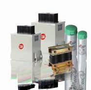
MAGNETIC CONTACTOR & MOTOR STARTER
|
|
|
- Noah Roberts
- 5 years ago
- Views:
Transcription

1 MAGNETIC CONTACTOR & MOTOR STARTER P
2


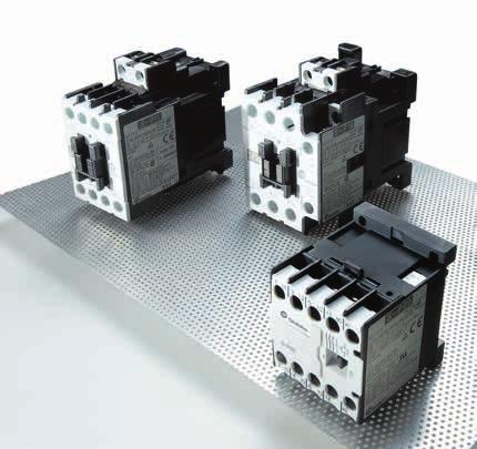
3 Functionalities and characteristics of Magnetic Contactor Configuration Composite magnetic switch (abbreviated as ) is comprised of a contactor for switching on and off current and a thermal overload relay for protecting the load. Functions a. Switching the control system for electric power transmission and distribution. b. Operation of the start and stop of motors. c. Electric power control for all kinds of industrial machinery, machine tools, injection molding machines. MAGNETIC CONTACTOR / STARTER Feature a. Products comply with multiple international standards. Compliant standards: JIS, JEM, IEC, EN, VDE Certificate: UL, UR, CSA, TUV, CE b. Auxiliary Contact Block designed for installing on the front and on the side can satisfy the spatial requirements of different operating environments. s AP-2P (1NO 1NC, 2NO, 2NC) AP-4P (2NO 2NC 4NO, 3NO 1NC) APS-11 (1NO 1NC) 1

4 c. Increase the reliability of auxiliary contacts (S-P60T and lower). Dual silver contact on movable contact Patterned interface on fixed contact 2MAGNETIC CONTACTOR / STARTER s Notes: Apply the above auxiliary terminal design can increase the reliability of the contacts and minimize the contact resistance variation. Descriptions of product characteristics S-P300 S-P400 Category Usability Product features Energy saving design with low power consumption for operating coils and operating VA capacity. Operating coils apply common AC/DC power, AC or DC operation, DC holding, absolutely free of electromagnetic noise. Wide range of operating voltage V, V, V, ease of customer use. Internationalization Compliant with IEC, CE, UL, TUV worldwide standards. Safety Spaced safety partition design: prevent short-circuit accidents caused by falling foreign objects. Safety trip mechanism design: when main contact melts down, auxiliary NC contact will break apart and open. Trip indication safety mechanism design: prevent external forces or human faulty activation which could lead to false function that bring about danger. Highly voltage drop withstand coil design (prevent the motor from starting at insufficient voltage [<65%Us is not allowed to activate]). s Contact material does not contain cadmium, which complies with RoHs requirements
5 Description of thermal overload relay Automatic temperature compensation design Bi-metal design can adjust and compensate automatically for ambient temperature changes, which increase the reliability of the product. Single unit installation base can be added for independent use -P12, -P18 can be installed to single unit installation base, which can be used independently on the track or be fixed on the installation plate. Safety terminal cover design for high safety level Terminal cover, is easy to install and complies with IEC degree of protection of IP 20. MAGNETIC CONTACTOR / STARTER Auxiliary terminal of thermal overload relay is 1NO 1NC The auxiliary contact are designed independently, which can be used for the control of two different power sources and are convenient for wiring Thermal overload relay reset/trip indicator can be seen easily and clear (Reset state) White rod will appear in the indicator window. (Trip) White rod shifted and unable to be seen directly. Switching of thermal overload relay between manual/automatic reset is easy (customers can switch by themselves according to their needs) Reset button Reset button Switch plate Reset button Switch plate Reset button -P12 Manual Automatic reset switching method Press reset button down and hold it; in the meantime, pull switch plate to the right to position A to lock reset rod and keep it in pressed down state, which then becomes the automatic reset state. Automatic Manual reset switching method Pull switch plate to the left to position H to have reset rod recoiled back upward and finish. -P20~-P600 Manual Automatic reset switching method Use cross screwdriver and align it with the cross hole on the top of reset button, engage and drive the button rotating it 90 counterclockwise to have the arrow points from H to A and keep reset button in pressed down state. Automatic Manual reset switching method Use cross screwdriver and align it with the cross hole on the top of reset rod, engage and drive the rod rotating it 90 clockwise to have the arrow points from A to H and the reset rod recoiled back to its original position. s 3


6 S-P Type designation S - 2 P 35T 220V Model S AC Magnetic contactor S-P Non-reversing/reversing Blank Non-reversing 2 Reversing P P 4MAGNETIC CONTACTOR / STARTER s S-2 P30T -P Type designation O-P11 O-2 P11 -P11PB -2 P Rated capacity T 35T 40T 50T 60T 80T 100T 125T 150T 200T 220T 300T 400T 600 Control circuit voltage EX. 110V 220V 380V 440V (Refer to P34) - 2 P 35T PB 380V/ 220V 28A E Model O AC Magnetic contactor without enclosure AC Magnetic contactor with enclosure 2 3 Non-reversing/reversing Blank Non-reversing 2 Reversing P P 4 Rated capacity T 35T 40T 50T 60T 80T 100T 125T 150T 200T 220T 300T 400T Push button Blank Non- Push button type PB With Push button type (O model is without PB) 6 Main circuit voltage EX 110V 220V 380V 440V (When main circuit voltage and control circuit voltage are the same, it will be blank.) 7 Control circuit voltage EX 110V 220V 380V 440V... (Refer to P34) 8 heater rated capacity EX 3.3A 6.5A 9A 11A 15A...350A... 9 Type Blank Compressor Type (2 heaters) E 3 heaters PP Differential Type
7 Magnetic Contactor / Starter AC control Type Magnetic Contactor Motor Starter Model Nonreversing S-P11 S-P12 without enclosure with enclosure with enclosure (push button) TOR Reversing S-2 P11 S-2 P12 Nonreversing O-P11 O-P12 Reversing O-2 P11 O-2 P12 Nonreversing -P11 -P12 Reversing -2 P11-2 P12 Nonreversing -P11PB -P12PB Standard -P12 E -P12 E Differential -P12PP -P12PP 240V 3.5/ 4.5/ / 4.5/ 13 MAGNETIC CONTACTOR / STARTER Rated Capacity Auxiliary Contact IEC EN DIN VDE 0660 AC 3 (kw/hp/a) UL 508 CSA-C22.2 AC3 (HP/A) IEC EN GB AC 15 3 ø 380/415V 5.5/ 7.5/ / 7.5/ V 5.5/ 7.5/ / 7.5/ V 5.5/ 7.5/ 9 5.5/ 7.5/ 9 660V 5.5/ 7.5/ 7 5.5/ 7.5/ 7 Continuous Current (Ith) AC1 (A) Rated insulation voltage (Ui) 1 ø 3 ø (V) AC660 AC ~120V 0.5/ / ~240V 2/ 10 2/ ~240V 3/ 9.6 3/ ~480V 7.5/ / ~600V 10/ 11 10/ 11 Continuous Current (Ith) AC1 (A) Rated insulation voltage (Ui) (V) AC600 AC600 NEMA 0 0 Contact Standard 1NO 1NO 1NC Special 1NC 2NC or 2NO 220V V Continuous Current (Ith) AC1 (A) Contact class (UL) A600, P600, Q300 A600, P600, Q300 Electrical Life AC3 1.6 Mil. 1.6 Mil. Magnetic Contactor Mechanical Life 10 Mil. 10 Mil. Operation (Time/Hour) Weight (kg) Appearance Dimensions (W H D) (mm) Installation dimension (mm) s Mechanical Interlock MPU-11 MPU-21 5
8 Magnetic Contactor / Starter AC control Magnetic Contactor Model Nonreversing without enclosure Reversing Nonreversing Reversing (A) 25 S-P15 S-P16 S-P21 (A) S-P25 S-2 P15 S-2 P16 S-2 P21 (A) S-2 P25 O-P15 O-P16 O-P21 (A) O-P25 O-2 P15 O-2 P16 O-2 P21 (A) O-2 P25 6MAGNETIC CONTACTOR / STARTER s Type Rated Capacity Auxiliary Contact Magnetic Contactor Motor Starter IEC EN DIN VDE 0660 AC 3 (kw/hp/a) UL 508 CSA-C22.2 AC3 (HP/A) IEC EN GB AC 15 with enclosure with enclosure (push button) TOR 3 ø Continuous Current (Ith) Rated insulation voltage (Ui) 1 ø 3 ø Continuous Current (Ith) Rated insulation voltage (Ui) NEMA Contact Continuous Current (Ith) Contact class Nonreversing Reversing Nonreversing Standard Differential 240V 380/415V 440V 550V 660V AC1 (A) (V) 100~120V 200~240V 200~240V 380~480V 550~600V AC1 (A) (V) Standard Special 220V 380V AC1 (A) (UL) Electrical Life AC3 Mechanical Life Weight Operation Appearance Dimensions (W H D) Installation dimension Mechanical Interlock (Time/Hour) (kg) (mm) (mm) -P15 -P16 -P21 (A) -P25-2 P15-2 P16-2 P21 (A) -2 P25 -P15PB -P16PB -P21PB (A) -P25PB -P12 E -P20 E -P20 E -P20 E(TA) -P12PP -P20PP -P20PP -P20(TA)PP 4.5/ 6/ / 6/ / 7.5/ / 8.5/ / 10/ / 10/ 18 11/ 15/ 21 12/ 16/ / 10/ / 10/ 16 11/ 15/ 21 12/ 16/ / 10/ / 10/ 13 11/ 15/ 17 12/ 16/ / 10/ 9 7.5/ 10/ 9 11/ 15/ 14 12/ 16/ AC660 AC660 AC660 AC660 1/ 16 2/ 24 2/ 24 3/ 17 3/ 17 3/ 17 5/ / 22 10/ 28 10/ 14 15/ 21 15/ 21 10/ 11 15/ 17 15/ AC600 AC600 AC NO 1NO 1NC 1NO 1NC (2NO 2NC) 1NO 1NC 1NC A600, Q300 A600, Q300 A600, Q Mil. 1.3 Mil. 1.3 Mil. 1.3 Mil. 10 Mil. 10 Mil. 10 Mil. 10 Mil MPU-11 MPU-21 MPU-21 MPU-21
9 30T 35T 40T 50T 60T S-P30T S-P35T S-P40T S-P50T S-P60T S-2 P30T S-2 P35T S-2 P40T S-2 P50T S-2 P60T O-P30T O-P35T O-P40T O-P50T O-P60T O-2 P30T O-2 P35T O-2 P40T O-2 P50T O-2 P60T -P30T -P35T -P40T -P50T -P60T MAGNETIC CONTACTOR / STARTER -2 P30T -2 P35T -2 P40T -2 P50T -2 P60T -P30TPB -P35TPB -P40TPB -P50TPB -P60TPB -P20 E(TA) -P20 E(TA) -P20 E(TA) -P60 E -P60 E(TA) -P20(TA)PP -P20(TA)PP -P20(TA)PP -P60PP -P60(TA)PP 7.5/ 10/ 30 9/ 12.5/ 35 11/ 15/ 44 15/ 20/ 58 19/ 25/ 65 15/ 20/ / 25/ 35 22/ 30/ 40 30/ 40/ 52 37/ 50/ 65 15/ 20/ / 25/ 27 22/ 30/ 40 30/ 40/ 52 37/ 50/ 65 15/ 20/ / 25/ 22 22/ 30/ 32 30/ 40/ 41 37/ 50/ 52 15/ 20/ / 25/ 18 22/ 30/ 26 30/ 40/ 34 37/ 50/ AC660 AC660 AC660 AC660 AC660 2/ 24 2/ 24 3/ 34 5/ 56 5/ 56 5/ 28 5/ / 40 10/ 50 10/ 50 10/ 28 10/ 28 15/ 42 20/ 54 20/ 54 20/ 27 20/ 27 20/ 27 30/ 40 40/ 52 30/ 32 30/ 32 30/ 32 40/ 41 50/ AC600 AC600 AC600 AC600 AC NO 2NC 2NO 2NC 2NO 2NC 2NO 2NC 2NO 2NC A600, Q300 A600, Q300 A600, Q300 A600, Q300 A600, Q Mil. 1.3 Mil. 1.3 Mil. 1.3 Mil. 1.3 Mil. 10 Mil. 10 Mil. 10 Mil. 6 Mil. 6 Mil s MPU-11 MPU-11 MPU-11 MPU-11 MPU-11 7
10 Magnetic Contactor / Starter AC control Magnetic Contactor Model Nonreversing without enclosure Reversing Nonreversing Reversing 80T 100T 125T 150T S-P80T S-P100T S-P125T S-P150T S-2 P80T S-2 P100T S-2 P125T S-2 P150T O-P80T O-P100T O-P125T O-P150T O-2 P80T O-2 P100T O-2 P125T O-2 P150T 8MAGNETIC CONTACTOR / STARTER s Type Rated Capacity Auxiliary Contact Magnetic Contactor Motor Starter IEC EN DIN VDE 0660 AC 3 (kw/hp/a) UL 508 CSA-C22.2 AC3 (HP/A) IEC EN GB AC 15 with enclosure with enclosure (push button) TOR 3 ø Continuous Current (Ith) Rated insulation voltage (Ui) 1 ø 3 ø Continuous Current (Ith) Rated insulation voltage (Ui) NEMA Contact Continuous Current (Ith) Contact class Nonreversing Reversing Nonreversing Standard Differential 240V 380/415V 440V 550V 660V AC1 (A) (V) 100~120V 200~240V 200~240V 380~480V 550~600V AC1 (A) (V) Standard Special 220V 380V AC1 (A) (UL) Electrical Life AC3 Mechanical Life Weight Operation Appearance Dimensions (W H D) Installation dimension Mechanical Interlock (Time/Hour) (kg) (mm) (mm) -P80T -P100T -P125T -P150T -2 P80T -2 P100T -2 P125T -2 P150T -P60 E(TA) -P120 E(TA) -P120 E(TA) -P120 E(TA) -P60(TA)PP -P120(TA)PP -P120(TA)PP -P120(TA)PP 22/ 30/ 80 30/ 40/ / 50/ / 60/ / 60/ 80 60/ 80/ / 100/ / 125/ / 60/ 75 60/ 80/ / 100/ / 125/ / 60/ 60 60/ 80/ 85 75/ 100/ / 125/ / 60/ 50 60/ 80/ 70 75/ 100/ 90 90/ 125/ AC660 AC660 AC660 AC / 80 15/ 68 25/ 68 30/ 80 50/ / / 65 60/ / / / 62 60/ / / AC600 AC600 AC600 AC NO 2NC 2NO 2NC 2NO 2NC 2NO 2NC A600, Q300 A600, Q300 A600, Q300 A600, Q Mil. 1.2 Mil. 1.2 Mil. 1.2 Mil. 6 Mil. 6 Mil. 6 Mil. 6 Mil MPU-50 Install by manufacturer MPU-125 MPU M5
11 200T 220T 300T 400T 600C S-P200T S-P220T S-P300T S-P400T M-600C S-2 P200T S-2 P220T S-2 P300T S-2 P400T RC-600C O-P200T O-P220T O-P300T O-P400T O-2 P200T O-2 P220T O-2 P300T O-2 P400T -P200T -P220T MAGNETIC CONTACTOR / STARTER -2 P200T -2 P220T -P220T E -P220T E -P400T E -P400T E -P600 E -P220TPP -P220TPP -P400TPP -P400TPP -P600PP 55/ 75/ / 85/ / 125/ / 150/ / 220/ / 150/ / 160/ / 220/ / 300/ / 420/ / 150/ / 160/ / 250/ / 340/ / 420/ / 150/ / 180/ / 250/ / 340/ / 420/ / 150/ / 180/ / 300/ / 380/ AC660 AC660 AC1000 AC1000 AC660 75/ / / / / / / / / / / / AC600 AC600 AC1000 AC NO 2NC 2NO 2NC 2NO 2NC 2NO 2NC 2NO 2NC A600, Q300 A600, Q300 A600, Q300 A600, Q300 A600, Q Mil. 1.2 Mil. 1.2 Mil. 1.2 Mil. 0.6 Mil. 6 Mil. 6 Mil. 6 Mil. 6 Mil. 6 Mil s M6 60 MPU-125 MPU-125 MPU-125 MPU-125 9
12 MAGNETIC CONTACTOR / STARTER Magnetic Contactor / Starter AC control Mini Contactor Type Rated Capacity Magnetic Contactor Motor Starter IEC EN DIN VDE 0660 AC 3 (kw/hp/a) UL 508 CSA-C22.2 AC3 (HP/A) Model Nonreversing S-P06 S-P09 without enclosure with enclosure Reversing S-2 P06 S-2 P09 Nonreversing O-P06 O-P09 Reversing Nonreversing Reversing with enclosure (push button) Nonreversing TOR 3 ø Standard Differential -P09PP -P09PP 240V 1.5/ 2/ / 3/ /415V 3/ 4/ 6.6 4/ 5.5/ 9 440V 3/ 4/ 6.5 4/ 5.5/ V 3/ 4/ 5 4/ 5.5/ V 3/ 4/ 4 4/ 5.5/ 5 Continuous Current (Ith) AC1 (A) Rated insulation voltage (Ui) (V) AC660 AC660 1 ø 3 ø 100~120V 0.25/ / ~240V 1/ 8 1.5/ ~240V 2/ 6.8 3/ ~480V 3/ 4.8 5/ ~600V 3/ 3.9 5/ 6.1 Continuous Current (Ith) AC1 (A) Thermal Overload Relay Standard With phase failure protection Type 09 Contactor Assembled Type Independently Installed Type Contactor Assembled Type Independently Installed Type Reset Mode Magnetic Contactor TOR Adjustment Range (A) Auxiliary Contact -P09PP Manual / Automatic S-P06, S-P09. Rating (A) Range (A) ~ ~ ~ ~ ~ ~ ~ ~4 5 4~ ~9 1NO 1NC Weight Auxiliary Contact IEC EN GB AC 15 Rated insulation voltage (Ui) (V) AC660 AC660 NEMA Contact Standard 1NO 1NO Special 1NC 1NC 220V V Continuous Current (Ith) AC1 (A) Contact class (UL) A600 A600 Dimensions (mm) (W H D) Electrical Life AC3 1.6 Mil. 1.6 Mil. Mechanical Life 10 Mil. 10 Mil. Operation (Time/Hour) Weight (kg) Magnetic Contactor Appearance Dimensions (W H D) (mm) Installation dimension (mm) Mechanical Interlock 50 4-M4 35 s Specification Table S-P06, S-P09 Description AC12V AC24V AC48V AC110V AC120V AC220V rated specifications marking 12V 50Hz 12V 60Hz 24V 50Hz 24V 60Hz 48~50V 50Hz 48~50V 60Hz 100V 50Hz 100~110V 60Hz 110~120V 50Hz 115~120V 60Hz 200~220V 50Hz 220V 60Hz Description AC230V AC240V AC380V AC440V AC480V AC550V rated specifications marking 230V 50Hz 230V 60Hz 220~240V 50Hz 240~260V 60Hz 346~380V 50Hz 380V 60Hz 400V 50Hz 400~440V 60Hz 415~440V 50Hz 460~480V 60Hz 500V 50Hz 500~550V 60Hz 10


13 DC control type Type designation - 2 P V Model DC Contactor Non-reversing/ reversing Blank 2 Non-reversing Reversing MAGNETIC CONTACTOR / STARTER -P11 3 P P 4 5 Rated capacity Control circuit voltage EX 12V 24V 48V...110V 220V... (Refer to P33) -2 P11 MDO DC control type Type designation MDO - 2 P V / 220V 28A E Model MDO DC Magnetic Switch without enclosure 2 Non-reversing/ reversing Blank 2 Non-reversing Reversing 3 P P MDO-P Rated capacity Main circuit voltage EX 110V 220V 380V 440V... (When main circuit voltage and control circuit voltage are the same, it will be blank.) 6 Control circuit voltage EX 12V 24V 48V...110V 220V... 7 heater rated capacity EX 3.3A 6.5A 9A 11A...21A... s Blank Compressor Type (2 heaters) 8 Type E 3 heaters MDO-2 P11 PP Differential 11
14 MAGNETIC CONTACTOR / STARTER Magnetic Contactor / Starter DC control Type Magnetic Contactor Motor Starter Nonreversing -P11 -P16 -P21 without enclosure with enclosure with enclosure (push button) Reversing -2 P11-2 P16-2 P21 Nonreversing MDO-P11 MDO-P16 MDO-P21 Reversing MDO-2 P11 MDO-2 P16 MDO-2 P21 Nonreversing Reversing Nonreversing TOR Standard -P12 -P20 -P20 Differential -P12PP -P20PP -P20PP 240V 3.5/ 4.5/ / 6/ / 7.5/ 24 Rated Capacity IEC EN DIN VDE 0660 AC 3 (kw/hp/a) UL 508 CSA-C22.2 AC3 (HP/A) 3 ø 380/440V 5.5/ 7.5/ / 10/ 18 11/ 15/ V 5.5/ 7.5/ 9 7.5/ 10/ 13 11/ 15/ V 5.5/ 7.5/ 7 7.5/ 10/ 9 11/ 15/ 14 Continuous Current (Ith) AC1 (A) ø 3 ø 110~120V 0.5/ 9.8 1/ 16 2/ ~240V 2/ 12 3/ 17 3/ ~240V 3/ 9.6 5/ / ~480V 7.5/ 11 10/ 14 15/ ~600V 10/ 11 10/ 11 15/ 17 Continuous Current (Ith) AC1 (A) NEMA Auxiliary contact 1NO or 1NC 1NO 1NC 1NO 1NC s Control coil voltage DC (V) 12/ 24/ 48/ 72/ 110/ 125/ 220 Electrical Life AC3 (10 thousand) Mechanical Life (10 thousand) Magnetic Contactor Weight (kg) Appearance Dimensions (W H D) Installation dimension (mm) (mm) 35 2-M M4 70 Mechanical Interlock MPU-11 MPU-11 MPU-11 12

15 S-PSC Capacitor use Type designation S - P 35 SC 220V Model S Electromagnetic contactor 2 P P (Non-reversing) MAGNETIC CONTACTOR / STARTER Rated capacity Purposes SC Applied to switching capacitor type. Control circult voltage EX 110V 220V 380V 440V Feature: a : applicable to rated voltage AC600V and below, with frequency at 50Hz/60Hz, and applied as a contactor for connecting and disconnecting low-voltage capacitors in parallel. b : contactor is equipped with current limiting resistor, which can suppress surge current output from capacitors when they are initially connected, which could effectively reduce the impact of surge current to the capacitors and increase the life and reliability of capacitors. s 13
 AC-6b 3 ø (kvar/a) 200~240V 6.7/ 18 8.5/ 22 10/ 26 15/ 39 20/ 48 25/ 66 35/ 92 400~440V 12.5/ 16 16.7/ 22 20/ 26 25/ 33 33.")
16 MAGNETIC CONTACTOR / STARTER Capacitor Contactor Type SC-P12 SC-P16 SC-P20 SC-P25 SC-P33 SC-P45 SC-P60 Rated insulation voltage (Ui) (V) Rated Capacity IEC EN DIN VDE 0660 AC 3 (kw/hp/a) AC-6b 3 ø (kvar/a) 200~240V 6.7/ / 22 10/ 26 15/ 39 20/ 48 25/ 66 35/ ~440V 12.5/ / 22 20/ 26 25/ / 44 45/ 59 60/ V 14/15 18/20 23/25 28/31 38/42 48/53 72/79 660~690V 18/ 15 24/ 20 30/ 25 36/ 30 48/ 40 58/ 49 75/ 63 Continuous Current (Ith) AC1 (A) Auxiliary Contact 2NO or 1NO 1NC 2NO 1NC 2NO 1NC 3NO 2NC 3NO 2NC 3NO 2NC 3NO 2NC Auxiliary Contact IEC EN AC12 (A) 100~120V ~220V ~440V ~600V Continuous Current (Ith) (A) Mechanical Life / Electrical Life (AC-6b) 440V (10 thousand) 100 / / / / / / / 30 Operation Frequency (time/ hour) Weight (kg) Magnetic Contactor Installation Dimensions (W H D) (mm) Dimensions (mm) M M M M xM Capacitor Unit s Capacitor Unit AP-40 A AP-40 B Magnetic Contactor Maximum operating power(kvar) 220~240V 400~440V 660~690V Max. peak current(a) S-P S-P S-P S-P40T S-P50T S-P60T S-P80T


17 SF Definite purposes Type designation SF - 20 C 2 M Model SF Definite purposes 2 Rated capacity 20, 25, 30, 35, 40 MAGNETIC CONTACTOR / STARTER 3 Type 4 C close type Contact structure 1 1 Pole 2 2 Pole 3 1 Pole + conductor contact SF25C2 5 Code of voltage Frequency H A L M B F 50Hz 24V 110~120V 200V 220V 208~240V 277V 60Hz 24V 110~120V 200V 220V 208~240V 277V Features: All contacts are AMP250 quick contacts, which saves wiring Compact size saving panel space. Standard dimensions of the installation holes, compliant with the installation dimensions of the product of the same grade made by other brands. Comply with Air-conditioning and Refrigeration Institute, USA ARI 780/790 standards. Certified by cul and compliant with the US UL508 standards. Certified by CSA, compliant with Canadian C.S.A. C22.2 No.14 standards. Comply with IEC standards, CE marking. Operating voltage of coil: 85%~105% rated voltage s 15
18 MAGNETIC CONTACTOR / STARTER Definite Purpose Magnetic Contactor SF C1 C2 C3 Type 1 Pole SF20C1 SF25C1 SF30C1 SF35C1 SF40C1 Type 2 Pole SF20C2 SF25C2 SF30C2 SF35C2 SF40C2 1Pole w/shunt SF20C3 SF25C3 SF30C3 SF35C3 SF40C3 Start Current(A) (Per Pole) Start Current(A) (Single Phase) (2 Pole) AC 240V / AC 277V AC 480V AC 600V AC 240V / AC 277V AC 480V AC 600V Rated Current w/resistance load (A) Full Rated Current (A) Mechanical / Electrical life ( 10 thousand ) 50/25 50/25 50/25 50/25 50/25 Operation frequency ( time / hour ) Control Voltage 50/60 Hz 24 / / 200 / 220 / / 277 Note: locked rotor current is the rotor current when the motor/compressor rotor is locked/immobilized, i.e. starting current as it is typically named. Applicable scope Applicable to the motor protective system in air-conditioning equipment, refrigerator or the control of the heater, motor, pump, fan, compressor in other industrial equipment. Operating environment Altitude below 2000m Ambient temperature: -40 ~65 (dew is not allowed) Relative humidity: 45~85%RH Installation direction The normal installation direction of SF series contactor is vertical, but is allowed to tilt 30 along the front and the rear directions; and is allowed to rotate 360 along the front direction for installation. s 16
19 Magnetic Control Relays Rated Capacity IEC AC15 (A) Type SR-P40 SR-P50 SR-P80 Auxiliary Contact 4NO 3NO 1NC 2NO 2NC 5NO 4NO 1NC 3NO 2NC 2NO 3NC 8NO 7NO 1NC 6NO 2NC 5NO 3NC 4NO 4NC 220V V MAGNETIC CONTACTOR / STARTER Rated insulation current (Ui) (V) Continuous Current (Ith) (A) Contact Class (UL) A600, Q300 A600, Q300 A600, Q300 Electrical Life (10 thousand) 50 and up 50 and up 50 and up Mechanical Life (10 thousand) Operation Frequency (time / hour) SR Anti-surge interference type Type SR-P40SA SR-P50SA SR-P80SA Contact structure 4NO 3NO 1NC 2NO 2NC 5NO 4NO 1NC 3NO 2NC 2NO 3NC 8NO 7NO 1NC 6NO 2NC 5NO 3NC 4NO 4NC Rated capacity (A) AC 12 (IEC) DC 12 (IEC) Continuous Current 110V V V V V V V V (lth)(a) contact class (UL) A600,Q300 A600,Q300 A600,Q300 Electrical life (10 thousand times) Mechanical Life (10 thousand times) s 17
20 MAGNETIC CONTACTOR / STARTER Auxiliary Contact Block AP Installation 2P FRONT MOUNTED TYPE 4P FRONT MOUNTED TYPE SIDE MOUNTED TYPE Type AP-20 AP-11 AP-02 AP-40 AP-31 AP-22 APS-11 APL-11 Contact 2NO 1NO 1NC 2NC 4NO 3NO 1NC 2NO 2NC 1NO 1NC 1NO 1NC Applicable contactor SR-P40, SR-P50 S-P11~ S-P80T -P11~ -P21 SR-P40, SR-P50 S-P11~ S-P80T -P11~ -P21 SR-P40, SR-P50 S-P11~ S-P60T -P11~ -P21 S-P125, S-P150T S-P200T, S-P220T S-P300T, S-P400T Rated Capacity AC 15 (A) 220V V 0.95 Operation current (Ith) (A) 16 Auxiliary Contact Block MAP Installation 2P FRONT MOUNTED TYPE 4P FRONT MOUNTED TYPE Type MAP-20 MAP-11 MAP-02 MAP-40 MAP-31 MAP-22 Contact 2NO 1NO 1NC 2NC 4NO 3NO 1NC 2NO 2NC Applicable contactor Rated Capacity AC 15 (A) S-P06, S-P V V 1.9 Continuous Current (Ith) (A) 10 Timer Type PTR-30 PTR-180 Contact 1NO 1NC 1NO 1NC Adjustable time (Sec) 0~30 0~180 Applicable contactor Rated Capacity AC 15 (A) SR-P40, SR-P50, S-P11~ S-P60T, -P11~ -P V V 0.95 Continuous Current (Ith) (A) 16 s Varistors: Anti-surge interference Type BACW220V BACW380V Applicable contactor SR-P40, SR-P50, S-P11~ S-P60T. 18
21 Push button PB Type PB2 PB3 MAGNETIC CONTACTOR / STARTER Contact structure Green Red Green Green Red External dimensions(mm) Wiring duc Wiring duct WET. 72.5g 110g Separate Mounting Unit + = s Type TOR UATP12 -P12 19
22 MAGNETIC CONTACTOR / STARTER eristics Type eristics Capacity (VA) S-P06 S-P09 S-P11 S-P15 S-P12 S-P16 S-P21 S-P25 S-P30T S-P35T S-P40T S-P50T S-P60T S-P80T S-P100T S-P125T S-P150T S-P200T S-P220T S-P300T S-P400T Impulse Operation Power Consumption (W) Operation Vot. (Ue) M-600C On 55~70 55~68 55~68 59~70 60~75 63~75 65~75 75~80 75~80 65~80 72~79 Off 35~50 34~48 34~48 36~52 40~57 40~57 40~55 40~55 40~60 20~50 59~66 Aux. OFF Close Time (ms) Open Time (ms) Aux. ON Contact ON Aux. OFF Aux. ON Contact ON Specification Table S-P11~S-P25, S-P30T~P220T, SR-P40~P80, SC-P12~P60 Description AC12V AC24V AC48V AC110V AC120V AC220V rated specifications marking 12V 50Hz 12V 60Hz 24V 50Hz 24V 60Hz 48~50V 50Hz 48~50V 60Hz 100V 50Hz 100~110V 60Hz 110~120V 50Hz 115~120V 60Hz 200~220V 50Hz 220V 60Hz Description AC230V AC240V AC380V AC440V AC480V AC550V rated specifications marking 230V 50Hz 230V 60Hz 220~240V 50Hz 240~260V 60Hz S-P300T~P400T 346~380V 50Hz 380V 60Hz 400V 50Hz 400~440V 60Hz 415~440V 50Hz 460~480V 60Hz 500V 50Hz 500~550V 60Hz Description AC48V AC110V AC220V AC380V AC550V rated specifications marking AC 48~50V 50/60Hz DC 48V AC V 50/60 Hz DC V AC 200~250V 50/60Hz DC 200~250V AC 265~450V 50/60Hz AC 440~575V 50/60Hz M-600C s Description AC110V AC120V AC220V AC230V AC260V 100V 50Hz 110~120V 50Hz 208~220V 50Hz 230~240V 50Hz 240~260V 50Hz rated specifications marking 100~110V 60Hz 115~120V 60Hz 220V 60Hz 230~240V 60Hz 260~280V 60Hz Description AC380V AC440V AC480V AC550V rated specifications marking 346~380V 50Hz 380V 60Hz 380~415V 50Hz 400~440V 60Hz 415~440V 50Hz 460~480V 60Hz 500V 50Hz 500~550V 60Hz 20

 only for 220 400 600 type 6 Type Blank PP 2 heaters (standard) or 3 heaters")
23 Thermal overload relay Type designation - P 20 E TA PP Model Thermal overload (overcurrent) relay 2 P P series MAGNETIC CONTACTOR / STARTER 3 Rated Capacity Type Blank E 2 heaters or Differential Type 3 heaters -P20TA 5 Contact/CT Blank Contact without TA with TA contact 20 type 28A~40A Ampere is left blank TA 60 type 67A~80A Ampere is left blank 120 type 105A~160A Ampere is left blank CT CT included (current transformer) only for type 6 Type Blank PP 2 heaters (standard) or 3 heaters Differential Type s 21
24 MAGNETIC CONTACTOR / STARTER Thermal Overload Relay Standard #3 With phase failure protection #3 Type Contactor Assembled Type -P12E -P20E -P20ETA Independently Installed Type -P12ER Contactor Assembled Type -P12PP -P20PP -P20TAPP Independently Installed Type -P12PPR Reset Mode Manual / Automatic Manual / Automatic Magnetic Contactor S-P11, S-P12, S-P15. S-P16, S-P21, S-P25, S-P30T, S-P35T, S-P40T. S-P25, S-P30T, S-P35T, S-P40T. Rating (A) Range (A) Rating (A) Range (A) Rating (A) Range (A) ~ ~ ~34 TOR Adjustment Range (A) ~ ~ ~ ~ ~ ~ ~ ~ ~ ~ ~ ~ ~ ~ ~ ~ ~ ~ ~ ~8 9 7~11 9 7~ ~ ~ ~ ~ ~24 Auxiliary Contact 1NO 1NC 1NO 1NC Weight 0.11/ / / 0.21 Dimensions (mm) (W H D) -P12(PP): P12(PP)R: P20(PP): P20TA(PP): s -P12(PP): -P12(PP)R: 35 Installation Dimensions (mm) M4 34x52 M4 35x56/60 52 M4 36.5x Note. 1. The purpose of using TOR is protecting load tripping. For protecting circuit, please choose circuit breaker. 2. When adjusting the rated current; please refer to the TOR range table above. Do not exceed its range. 3. (E): 3 Elements 4. : The rating current of -P12 can only use up to "11A" when combined with S-P11. Correct Incorrect
25 Standard With phase failure protection Type Contactor Assembled Type -P60E -P60ETA -P120E -P120ETA Independently Installed Type Contactor Assembled Type -P60PP -P60TAPP -P120PP -P120TAPP Independently Installed Type MAGNETIC CONTACTOR / STARTER Reset Mode Manual / Automatic Manual / Automatic Magnetic Contactor S-P50T, S-P60T, S-P80T. S-P60T, S-P80T. S-P100T, S-P125T, S-P150T. Rating (A) Range (A) Rating (A) Range (A) Rating (A) Range (A) Rating (A) Range (A) 11 9~ ~ ~ ~130 TOR Adjustment Range (A) 15 12~ ~ ~ ~ ~ ~ ~ ~ ~ ~ ~ ~65 Auxiliary Contact 1NO 1NC 1NO 1NC Weight 0.28/ / Dimensions (mm) (W H D) -P60(PP): P60TA(PP): P120(PP): P120TA(PP): s Installation Dimensions (mm) M5 86x M5 119x Note. 1. The purpose of using TOR is protecting load tripping. For protecting circuit, please choose circuit breaker. 2. When adjusting the rated current; please refer to the TOR range table above. Do not exceed its range. 3. (E): 3 Elements Correct Incorrect 23
26 MAGNETIC CONTACTOR / STARTER 220T 400T 600CT -P220TE -P400TE -P600E -P220TPP -P400TPP -P600PP Manual / Automatic Manual / Automatic Manual / Automatic S-P200T, S-P220T. S-P300T, S-P400T. M-600C Rating (A) Range (A) Rating (A) Range (A) Rating (A) Range (A) 80 60~ ~ ~ ~ ~ ~ ~ ~ ~ ~ ~ ~ ~ ~440 1NO 1NC 1NO 1NC 1NO 1NC / TOR: TOR W/CT: s Ø 5.2 Ø 5.2 Ø M4 36.5x Ø
27 Thermal overload (overcurrent) relay Tripping eristic -P12E tripping characteristic curve -P18E below 6.5A tripping characteristic curve MAGNETIC CONTACTOR / STARTER operation time cold status heat status operation time cold status heat status Multiples of rated current Multiples of rated current -P18E above 9A tripping characteristic curve -P20E below 6.5A tripping characteristic curve operation time cold status heat status operation time cold status heat status Multiples of rated current Multiples of rated current s 25
28 MAGNETIC CONTACTOR / STARTER Thermal overload (overcurrent) relay Tripping eristic -P20ETA above 9A tripping characteristic curve -P60ETA tripping characteristic curve operation time cold status heat status operation time cold status heat status Multiples of rated current Multiples of rated current -P120ETA tripping characteristic curve -P220ECT P400ECT -P220TE P400TE 130A tripping characteristic curve operation time cold status operation time cold status heat status heat status s Multiples of rated current Multiples of rated current 26
29 Thermal overload (overcurrent) relay Tripping eristic -P220ECT -P400ECT -P220TE -P400TE 160A tripping characteristic curve -P600ECT tripping characteristic curve MAGNETIC CONTACTOR / STARTER operation time cold status heat status operation time cold status heat status Multiples of rated current Multiples of rated current -P12PP tripping characteristic curve -P20TAPP tripping characteristic curve operation time over-load protection curve Phase failure protection cure operation time over-load protection curve Phase failure protection curve operation time s Multiples of rated current Multiples of rated current Mu 27
30 MAGNETIC CONTACTOR / STARTER Thermal overload (overcurrent) relay Tripping eristic -P60TAPP tripping characteristic curve -P120TAPP tripping characteristic curve operation time over-load protection curve Phase failure protection curve operation time over-load protection curve Phase failure protection curve Multiples of rated current Multiples of rated current -P220CTPP P400CTPP P600CTPP -P220TPP P400TPP tripping characteristic curve operation time over-load protection curve Phase failure protection curve s Multiples of rated current 28

31 Reduced voltage Starter (Y-D Starter) Type designation - O P35 T 380V/ 220V 28A E Model Star-delta Starter MAGNETIC CONTACTOR / STARTER 2 Type O without enclosure E A with enclosure Push button Indicator lamp with enclosure Push button Indicator lamp Ammeter 3 Rated capacity O-P60 4 Contact / CT Blank CT not included T CT included 5 Main circuit voltage EX 110V 220V 380V 440V... When main circuit voltage and control circuit voltage are the same, it will be blank.) E-P21 6 Control circuit voltage EX 110V 220V 380V 440V... 7 heater rated capacity EX 40A 54A...350A... 8 Type Blank Standard (2 heaters) E 3 heaters PP Differential s 29
32 MAGNETIC CONTACTOR / STARTER Structure, principle When starting by - starting method, starting current and torque of motor will be reduced to 1/3 of those of direct starting; the purpose is to suppress starting current, but somehow it also suppresses torque at the same. Comparison table between direct starting and - starting (the values in the table are all shown in %) Starting method Linear current (starting current) When starting Torque Linear voltage (power voltage) Linear current (loading current) In operation Phase current Direct starting / 3=58 - starting 600 1/3= /3= / 3=58 Operating circumstance (1) Unloaded starting circumstance. e.g.: (1-1) Starting the driving shaft of machine tool. (1-2) Typical starting of woodworking machinery. (1-3) Starting of grinding, drilling machines etc. (1-4) Motor with clutch. (2) Light loading circumstance. e.g.: (2-1) Small-size belt conveyer. (2-2) Light loading air compressor or water pump. (2-3) Stamping press etc. (3) Equipment that needs to limit starting current. (4) Equipment that needs to reduce starting impact. s Notes (1) When speed of the motor exceeds 80% of rated value, it is the optimal time to perform - switching. (2) Starting time of can be defined according to motor capacity (kw). Use the equation t = 4 +2 to derive the time required (second) (3) When starting by -, ensure the power supply capacity is sufficient to prevent voltage drop in power supply during transition from starting to operation, which could cause the contactor to break or burn out. Remarks: 1. Three-phase induction motor can be started by the following methods: (1) Full voltage direct starting. (2) Reduced voltage starting. (2-1) - starting. (2-2) Reactor starting. (2-3) Self-coupled transformer starting. (2-4) Primary resistor starting. 2. If the motor is not limited by its starting method, direct starting can be applied for all large or small-size models. If all motors are started by direct starting, the stability of system power supply will definitely be impacted. When starting, all the appliances connected to the same loop circuitry will be influenced by voltage drop. Lamps will flash and the motor will trip, due to overload of increased current resulting from low voltage. Therefore, national standards or power company internal regulations always define the circumstances that require reduced voltage starting. 30

 MCM S-P21 S-P35T S-P50T S-P60T S-P80T S-P100T S-P125T S-P150T S-P220T MCD S-P21 S-P35T S-P50T S-P60T S-P80T S-P100T S-P125T S-P150T S-P220T MCS S-P11 S-P16 S-P21 S-P21 S-P35C")
33 Reduced voltage starter (Y-D Starter) Type Rated capacity Model Open O-P21 O-P35 O-P50 O-P60 O-P80 O-P100 O-P125 O-P150 O-P220 O-P21T O-P35T O-P50T O-P60T O-P80T O-P100T O-P125T O-P150T O-P220T Enclosure E-P21 E-P35 E-P50 E-P60 E-P80 E-P100 E-P125 E-P150 E-P220 A-P21 A-P35 A-P50 A-P60 A-P80 A-P100 A-P125 A-P150 A-P220 Rated voltage kw HP kw HP kw HP kw HP kw HP kw HP kw HP kw HP kw HP 200~220V ~440V MAGNETIC CONTACTOR / STARTER AC contactor Wire (m ) MCM S-P21 S-P35T S-P50T S-P60T S-P80T S-P100T S-P125T S-P150T S-P220T MCD S-P21 S-P35T S-P50T S-P60T S-P80T S-P100T S-P125T S-P150T S-P220T MCS S-P11 S-P16 S-P21 S-P21 S-P35C S-P35T S-P50T S-P50T S-P60T -P20 -P60 -P60 -P120 -P120 -P120 -P220T -P220T -P400T TOR -P20TA -P60TA -P60TA -P120TA -P120TA -P120TA -P220T -P400T -P400T Line 2.5~16 2.5~25 2.5~35 2.5~50 10~70 10~95 35~150 35~150 35~240 Load 2.5~10 2.5~16 2.5~25 2.5~35 4~50 4~70 10~95 10~90 16~150 Control circuit 1~2.5 1~2.5 1~2.5 1~2.5 1~2.5 1~2.5 1~2.5 1~2.5 1~2.5 Note: 1. E-P21~P220 is with enclosure, push button, indicator light and door lock. 2. A-P21~P220 is with enclosure, push button, indicator light, door lock, and current meter. 3. O-P21~P220 is attached with CT as current meter. s A-P50 A-P50 31
34 MAGNETIC CONTACTOR / STARTER Wiring Connection with Breaker TOR tion table TOR Symbol descriptions MC Magnetic contactor GL Indicator light (green) A Ammeter TOR Thermal overload (overcurrent) relay RL Indicator light (red) Fuse Fuse RT Time limited relay CT Current transformer PB Push button 1. The numbers in the parentheses are applicable to Model P80~P220 type. 2. Setting time for RT (Timer): t = kw ( 1 second) s 32
35 tion Table - Starter Heater selection table (A) Motor output kw (HP) selection of - Starter A B ~220V 380~440V A B A B A B A B A B A B A B A B A B (2) 3 (4) (2 1/2) 3.7 (5) (3) 4.5 (6) MAGNETIC CONTACTOR / STARTER 11 3 (4) 5.5 (7 1/2) -P20 -P (5) 7.5 (10) (6) 10 (13) (7 1/2) 11 (15) (8) 14 (19) (10) 15 (20) 33 9 (12 1/2) 19 (25) -P20TA -P20TA -P60 -P60 -P60 -P (15) 22 (30) (19) 26 (35) (20) 30 (40) (25) 37 (50) (30) 45 (60) - P60TA -P60TA -P60TA -P120 -P120 -P120 -P120 -P120 -P (34) 50 (67) (40) 55 (75) (50) 75 (100) - P120TA - P120TA -P120TA -P120TA -P120TA -P120TA -P220T -P220T -P220T -P220T (60) 90 (125) (75) 110 (150) -P400T -P400T s (85) 132 (200) (100) 150 (200) - P400T (150) 200 (260) 33
36 MAGNETIC CONTACTOR / STARTER tion Table Direct On-Line Starter Motor rated capacity kw (HP) Heating element rating (A) (1/47) 0.13A 0.1~0.16A (1/30) 0.2A 0.16~0.24A 0.04 (1/19) 0.32A 0.24~0.4A 0.09 (1/8) 0.5A 0.4~0.6A 0.12 (1/6) 0.8A 0.6~1.0A 0.25 (1/3) 1.3A 1.0~1.6A S-P06 S-P09 3 ø 200V~220V tion of the contactor 0.37 (1/2) 2.0A 1.6~2.4A 0.75 (1) 3.2A 2.4~4.0A 1.1 (1 1/2) 5A 4.0~6.0A 1.5 (2) 7.5A 6.0~9.0A 0.03 (1/25) 0.25A 0.19~0.31A 0.05 (1/15) 0.4A 0.3~0.5A 0.1 (1/8) 0.6A 0.45~0.75A 0.15 (1/5) 0.9A 0.7~1.1A 0.2 (1/4) 1.2A 0.9~1.5A 0.3 (2/5) 1.7A 1.3~2.1A 0.4 (1/2) 2.1A 1.6~2.6A 0.75 (1) 3.3A 2.5~4.1A 1.1 (1 1/2) 4.4A 3.4~5.4A 1.5 (2) 6.5A 5~8A 2.2 (3) 9A 7~11A S-P11, S-P12 S-P15, S-P16 S-P21 S-P25 S-P30T S-P35T S-P40T 3 (4) 11A 9~13A 3.7 (5) 15A 12~18A 5.5 (7 1/2) 21A 17~24A 6.5 (8 1/2) 28A 22~34A 7.5 (10) 9 (12 1/2) 33A 28~38A S-P50T S-P60T S-P80T 11 (15) 40A 32~48A 15 (20) 54A 43~65A 19 (25) 67A 54~80A 22 (30) 80A 60~100A 25 (35) 105A 80~130A 30 (40) 37 (50) 130A 100~160A 45 (60) 160A 120~200A S-P100T S-P125T S-P150T S-P200T S-P220T s 55 (75) 65 (85) 200A 150~250A S-P300T S-P400T 75 (100) 260A 200~320A 90 (125) 110 (150) 350A 260~440A M-600C 132 (180) 160 (220) 500A 400~600A 34
37 tion Table Direct On-Line Starter Motor rated capacity kw (HP) Heating element rating (A) (1/30) 0.13A 0.1~0.16A 0.04 (1/19) 0.2A 0.16~0.24A 0.09 (1/8) 0.32A 0.24~0.4A 0.18 (1/4) 0.5A 0.4~0.6A 0.25 (1/3) 0.8A 0.6~1.0A 0.37 (1/2) 1.3A 1.0~1.6A 0.55 (3/4) 0.75 (1) 2.0A 1.6~2.4A S-P06 S-P09 3 ø 380V~440V tion of the contactor MAGNETIC CONTACTOR / STARTER 1.1 (1 1/2) 3.2A 2.4~4.0A 1.5 (2) 2.2 (3) 5A 4.0~6.0A 3 (4) 7.5A 6.0~9.0A 0.05 (1/15) 0.25A 0.19~0.31A 0.1 (1/8) 0.4A 0.3~0.5A 0.2 (1/4) 0.6A 0.45~0.75A 0.3 (2/5) 0.9A 0.7~1.1A 0.4 (1/2) 1.2A 0.9~1.5A 0.75 (1) 1.7A 1.3~2.1A 1.1 (1 1/2) 2.1A 1.6~2.6A 1.5 (2) 3.3A 2.5~4.1A 2.2 (3) 4.4A 3.4~5.4A 3 (4) 6.5A 5~8A 3.7 (5) 9A 7~11A 4 (5 1/2) 4.5 (6) 11A 9~13A 5.5 (7 1/2) 7.5 (10) 15A 12~18A S-P11, S-P12 S-P15, S-P16 S-P21 S-P25 S-P30T S-P35T S-P40T 11 (15) 21A 17~24A 12 (16) 15 (20) 28A 22~34A 19 (25) 33A 28~38A 22 (30) 40A 32~48A 25 (35) S-P50T S-P60T S-P80T 30 (40) 54A 43~65A 37 (50) 67A 54~80A 45 (60) 50 (70) 80A 60~100A S-P100T S-P125T S-P150T 60 (80) 105A 80~130A 75 (100) 130A 100~160A 90 (125) 160A 120~200A 110 (150) 200A 150~250A 132 (180) S-P200T S-P220T S-P300T S-P400T s 150 (200) 260A 200~320A 160 (220) 220 (330) 250 (350) 315 (420) 350A 260~440A 500A 400~600A M-600C 35
38 MAGNETIC CONTACTOR / STARTER tion Table Direct On-Line Starter Motor rated capacity kw (HP) Heating element rating (A) 0.06 (1/12) 0.13A 0.1~0.16A 0.09 (1/8) 0.2A 0.16~0.24A 0.12 (1/6) 0.32A 0.24~0.4A 0.18 (1/4) 0.5A 0.4~0.6A 0.37 (1/2) 0.8A 0.6~1.0A 0.55 (3/4) 1.3A 1.0~1.6A 0.75 (1) 1.1 (1 1/2) 2.0A 1.6~2.4A S-P06 S-P09 3 ø 500V~550V tion of the contactor 1.5 (2) 3.2A 2.4~4.0A 2.2 (3) 5A 4.0~6.0A 3 (4) 4 (5 1/2) 7.5A 6.0~9.0A 0.12 (1/6) 0.25A 0.19~0.31A 0.18 (1/4) 0.4A 0.3~0.5A 0.25 (1/3) 0.6A 0.45~0.75A 0.37 (1/2) 0.9A 0.7~1.1A 0.55 (3/4) 1.2A 0.9~1.5A 0.75 (1) 1.7A 1.3~2.1A 1.1 (1 1/2) 2.1A 1.6~2.6A 1.5 (2) 3.3A 2.5~4.1A 2.2 (3) 4.4A 3.4~5.4A 4 (5 1/2) 6.5A 5~8A S-P11, S-P12 S-P15, S-P16 S-P21 S-P25 S-P30T S-P35T S-P40T 4.5 (6) 9A 7~11A 5.5 (7 1/2) 7.5 (10) 11A 9~13A 11 (15) 15A 12~18A 12 (16) 21A 17~24A 15 (20) 19 (25) 28A 22~34A 22 (30) 33A 28~38A S-P50T S-P60T S-P80T 30 (40) 40A 32~48A 37 (50) 54A 43~65A 45 (60) 67A 54~80A 50 (70) S-P100T S-P125T S-P150T 60 (80) 80A 60~100A s 75 (100) 105A 80~130A 90 (125) 130A 100~160A S-P200T S-P220T 110 (150) 132 (180) 160A 120~200A S-P300T S-P400T 150 (200) 200A 150~250A 160 (220) 260A 200~320A 220 (330) 350A 260~440A M-600C (420) 500A 400~600A
39 tion Table Magnetic contactor selection Capacitor use 3 Phase Rated Capacity kvar(a) Model 200~220V 400~440V 500V 600V S-P11,12 3(8.5) 4(6) S-P21 4.5(14) 9(13) S-P30T,S-P35T 6(18) 12(18) S-P40T 8.5(25) 15(23) S-P50T 12(35) 20(30) MAGNETIC CONTACTOR / STARTER S-P60T 13(40) 24(35) 25(30) 25(25) S-P80T 15(50) 25(40) 30(35) 30(30) S-P100T 22(65) 40(60) 45(50) 45(45) S-P125T 24(72) 46(67) 50(55) 50(50) S-P150T 25(80) 51(75) 60(70) 60(60) S-P220T 50(150) 96(140) 110(130) 110(110) S-P300 65(200) 120(180) 130(150) 130(130) S-P400 85(250) 170(250) 200(230) 200(200) S-C (500) 350(500) 350(400) 400(400) Single Rated Capacity kvar(a) Model Single Phase 3 Phase in 200~220V 400~440V 500V 600V S-P11,12 1.7(8.5) 2.4(6) S-P21 2.8(14) 5(13) S-P30T,S-P35T 3.6(18) 7(18) S-P40T 5(25) 9(23) S-P50T 7(35) 12(30) S-P60T 8(40) 14(35) 20(40) 25(40) S-P80T 10(50) 15(40) 25(50) 30(50) S-P100T 13(65) 25(60) 30(60) 35(60) S-P125T 14(72) 27(67) 33(70) 37(70) S-P150T 15(80) 30(75) 35(80) 40(80) S-P220T 30(150) 55(140) 75(150) 90(150) s S-P300 40(200) 72(180) 90(180) 100(180) S-P400 50(250) 100(250) 120(250) 140(250) S-C (500) 200(500) 250(500) 300(500) Note: Single phase: kvar = (Hz) ( F) (V)2 3 phase: 3 x single phase kvar 37
40 MAGNETIC CONTACTOR / STARTER Installation notes Operating environment Altitude below 3000m Ambient temperature: -30 ~+70 (dew is not allowed) Relative humidity: Relative humidity could not exceed 50% when the surrounding temperature is +40oC. For lower temperature, the relative humidity can be higher. The average maximum relative humidity for the month with the highest humidity is 90%, and the average lowest temperature of that month is +25oC. Please consider the possibility of frosting on the surface of the product due to temperature change. Withstand vibration 10Hz 55Hz 2G Withstand impact 5G Storage temperature: (dew is not allowed) Please do not install in a place that contains dust, moisture, salt, oil stains, or corrosive or flammable gases. After switch installed, please add temporary protection to avoid harmful substances like dust or moisture etc coming into contact with it, if the switch is not to be used for a long period of time. operating voltage should be applied within 85~110% of rated voltage. If higher than 110%, the coil life will be reduced, or the coil could burn out if lower than 85%. Installation direction The regular installation direction of the contactor is vertical, but is allowed 20 tilt along all directions. Refer to the figure below. Regular installation Tilt installation s Downward installation X Upward installation X 38 Note. If installation dimensional drawing is required, please contact regional distributor or b.export@seec.com.tw


41
42 MOTOR CONTROL (CONTACTOR/ / M), CIRCUIT BREAKER (MCCB/ ELCB/ EMCCB/ MCB), AIR CIRCUIT BREAKER, AUTOMATIC TRANSFER SWITCHES (Panel Board Type/ Residential Unit Use), SURGE PROTECTIVE DEVICE, LOW VOLTAGE POWER CAPACITORS, SMART METER, INVERTER Breaker & switchgears overseas sales dept. 3F, No.9, Sec. 1, Chang-an E. Rd., Zhongshan Dist., Taipei City 10441, Taiwan T F b.export@seec.com.tw Headquarters 16F, No.88, Sec. 6, Zhongshan N. Rd., Shilin Dist., Taipei City 11155, Taiwan T F Distributor B180717E.-P-OB
MAGNETIC CONTACTOR & MOTOR STARTER
 http://www.seec.com.tw http://circuit-breaker.seec.com.tw MAGNETIC CONTACTOR & MOTOR STARTER P Functionalities and characteristics of Magnetic Contactor Configuration Composite magnetic switch (abbreviated
Ktec Contactors and thermal overloads
 Contactors and thermal overloads Techna KTEC series contactors provide a complete solution for your ac contactor requirements.the range carries TUV, UL & CSA certification, for use in Europe, North America
Meta Solution. Contactors and Overload relays
 Meta Solution Contactors and Overload relays Meta Solution New generation of Contactors from LSIS Contactors and Overload Relays Metasol Contactors Designed to show superior technology: The Metasol series
Manual Motor Starters. Meta-MEC
 Manual Motor Starters Meta-MEC Manual Motor Starters LS Meta-MEC Manual Motor Starters provide completed ranges up to 100A 45 mm 55 mm 32AF 2 2 45 mm 70 mm 63AF 100AF 3 3 Manual LS Meta-MEC Motor Starters
AF series contactors (9 2650)
") R E32527 R E39322 contactors General purpose and motor applications AF series contactors (9 2650) 3- & 4-pole contactors General purpose up to 2700 A Motor applications up to 50 hp, 900 kw NEMA Sizes 00
R E32527 R E39322 contactors General purpose and motor applications AF series contactors (9 2650) 3- & 4-pole contactors General purpose up to 2700 A Motor applications up to 50 hp, 900 kw NEMA Sizes 00
Essential equipment for all your requirements
 NEW CTX CONTACTORS Essential equipment for all your requirements 9 A TO 310 A THREE-POLE INDUSTRIAL CONTACTORS CTX three-pole industrial contactors, a sense of family The new range of CTX contactors provides
AF40... AF96 3-pole contactors Technical data
 Main pole - Utilization characteristics according to IEC Standards IEC 60947- / 60947-4- and EN 60947- / 60947-4- Rated operational voltage Ue max. 690 V Rated frequency (without derating) 50 / 60 Hz Conventional
AF40... AF96 3-pole contactors 30 to 60 hp at 480 V AC AC / DC operated with 1 N.O. + 1 N.C. auxiliary contacts
 AF4... AF96 -pole contactors to 6 hp at 48 V AC AC / DC operated with N.O. N.C. auxiliary contacts Description AF4... AF96 contactors are mainly used for controlling -phase motors and power circuits up
Contactor Catalogue. According to CE, IEC 947, EN Pole & 4 Pole Contactors 4kW - 160kW Thermal Overload
 According to CE, IEC 947, EN 60947 Contactor Catalogue 3 Pole & 4 Pole Contactors 4kW - 160kW Thermal Overload Mini-Contactors 4kW - 5.5kW DC Contactors Mini-Relays 10A Motor Starter DOL, Star-Delta Capacitor
CI-TI Contactors and motor starters Types CI 61 - CI 98
 Data sheet CI-TI Contactors and motor starters s CI 6 - CI 98 Contactors CI 6, CI 7, CI 86 and CI 98 switch powers of up to 0 kw, 7 kw, 45 kw and 55 kw respectively under 80 V - loads. Accessories include
AF series contactors (9 2650)
") R E32527 R E39322 contactors General purpose and motor applications AF series contactors (9 2650) 3- & 4-pole contactors General purpose up to 2700 A Motor applications up to 50 hp, 900 kw NEMA Sizes 00
R E32527 R E39322 contactors General purpose and motor applications AF series contactors (9 2650) 3- & 4-pole contactors General purpose up to 2700 A Motor applications up to 50 hp, 900 kw NEMA Sizes 00
Meta Solution. Contactors and Overload relays
 Meta Solution Contactors and Overload relays New generation of Contactors from LS Industrial Systems Contactors and Overload Relays Metasol Contactors Designed to show superior technology: The Metasol
Selection Guide Motor Control Device Solutions
 Selection Guide Motor Control Device Solutions Expect more and get it from c3controls. Our portfolio of Motor Control Devices consists of worldclass products designed and manufactured to meet your requirements
22AF 40AF AF 150AF 225AF 400AF 800AF
 Contactors MC-Series UL508 E108780 Contactor 3 Pole Standards and Certifications UL508 IEC 60947-2 & IEC 60947-4-2 CSA C22.2 No.14 Features 8 Frame Sizes 1/2HP up to 600HP @ 480V AC Screw Terminals (Lug
Approved Standards. Motor Contactor. Main contactor. Accessoires. 21 Motor Contactor J7KN
 Motor Contactor Main contactor AC & DC operated Integrated auxiliary contacts Screw fixing and snap fitting (35 mm DIN rail) up to 45 kw Range from 4 to 110 kw (AC 3, 380/415V) Finger proof ( VBG 4) Accessoires
AF09... AF30 3-pole Contactors up to 25 HP / 600 VAC
 AF09... AF0 -pole Contactors up to 25 HP / 600 VAC Contactors and Overload Relays Overview.../0 AF09... AF0 -pole Contactors.../2 Main Technical Data.../8 Main Accessory Fitting Details.../2 Main Accessory.../24
AF / AF12Z pole Contactors AC / DC Operated - with Screw Terminals
 Technical Datasheet 1SBC101404D0201 24/03/11-30-10-.. / Z-30-10-.. 3-pole Contactors AC / DC Operated - with Screw Terminals (Z) contactors are used for controlling power circuits up to 690 V AC and 220
Industrial Contactors CTX 3 3P 185A - 800A
 87045 LIMOGES Cedex Telephone: +33 5 55 06 87 87 FAX: +33 5 55 06 88 88 Industrial Contactors CONTENTS PAGES 1. Description - Use... 1 2. Range... 1 3. Overall dimensions... 1 4. Installation - Connection...
AF09... AF30 3-pole Contactors up to 20 HP / 480 VAC
 AF0... AF0 -pole Contactors up to 20 HP / 480 VAC Contactors and Overload Relays Overview...2 AF0... AF0 -pole Contactors Ordering Details...4 Main Technical Data...20 DC Circuit switching...2 Main Accessory
HEAVY DUTY POWER RELAYS FEATURES
 VDE VC HEAVY DUTY POWER RELAYS VC RELAYS Faston terminal Screw terminal mm 9 FEATURES VC power relays are designed for controlling heavy duty loads safely: Contact gap of 3 mm or more -point contacts for
TeSys contactors. Use in category DC-1 (resistive loads; time constant L/R y 1 ms) Rated operational current Ie. to be wired in series
 Rated operational current Ie. to be wired in series") Selection 3-pole shockproof contactors FG d.c. supply Selection guide for utilisation categories DC-1 to DC-5 Use in category DC-1 (resistive loads; time constant L/R y 1 ms) Rated operational current
Selection 3-pole shockproof contactors FG d.c. supply Selection guide for utilisation categories DC-1 to DC-5 Use in category DC-1 (resistive loads; time constant L/R y 1 ms) Rated operational current
Series KTU7 UL489 Molded Case Circuit Breakers
 Series KTU7 UL489 Molded Case Circuit Breakers Versatile, convenient and space saving for a variety of applications Sprecher+Schuh s KTU7 series of UL Molded Case Circuit Breakers are UL489 and CE listed
B115...B180 RF200 RFN200 B250...B400 RF400 RFN400
 Page -2 Page -4 Page -6 FOR BG SERIES MINI-CONTACTORS Type RF9, phase failure sensitive, manual resetting Type RFA9, phase failure sensitive, automatic resetting Type RFN9, non-phase failure sensitive,
Technical Information
 C5 C5- C5- C5- C5- C5-550 ➊ 700 860 1000 1200 Rated Insulation Voltage U i to IEC 947-1 [V] 1000V 1000V 1000V 690V 690V UL/CS [V] 600V Rated Impulse Voltage U imp C5-550 / 700 / 860 [kv] 3.5 C5-1000 /
Control Power V AC, 50/60 Hz 150-C30NBD 150-C30FHD
 Bulletin Product Selection Open Type and Non-Combination Enclosed (IP, NEMA /) Controllers For use with Line-Connected Motors Rated Voltage [V AC] / Motor Current [A]...... Max. kw, Hz Max. Hp, Hz Control
3 - Protection components Motor circuit-breakers
 Contents 0 - Protection components Motor circuit-breakers protection components for the motor protection Thermal-magnetic motor circuit-breakers Selection guide..............................................page
Motor Protection Circuit Breakers
 Motor Protection Circuit Breakers About us Larsen & Toubro is a technologydriven USD 9.8 billion company that infuses engineering with imagination. The Company offers a wide range of advanced solutions
CTX 3 Control relays Cat. N (s) : /06/09..14/16/19..24/26/29
 : /06/09..14/16/19..24/26/29") 87045 LIMOGES Cedex Telephone: +33 5 55 06 87 87 FAX: +33 5 55 06 88 88 CTX 3 Control relays Cat. N (s) : 4 168 00..04/06/09..14/16/19..24/26/29 CONTENTS PAGES 1. Description - Use... 1 2. Range... 1 3.
87045 LIMOGES Cedex Telephone: +33 5 55 06 87 87 FAX: +33 5 55 06 88 88 CTX 3 Control relays Cat. N (s) : 4 168 00..04/06/09..14/16/19..24/26/29 CONTENTS PAGES 1. Description - Use... 1 2. Range... 1 3.
ASL09..S 3-pole Contactors - Spring Terminals
 4 kw 5 hp ASL09..S 3-pole Contactors - Spring DC Operated Description - 3-pole contactors with spring terminals, - N.C. or N.O. built-in auxiliary contact, - Low coil consumption, - Polarity on the coil
Series KTU7 UL489 Molded Case Circuit Breakers
 Series UL489 Molded Case Circuit Breakers Versatile, convenient and space saving for a variety of applications Sprecher+Schuh s series of UL are UL489 and CE listed for global applications. The current
YS Series Contactors YS1N- F11 ****
 YS Series YS Series Contactors Key features of the YS Series include: Compact size AC and C coil, reversing and non-reversing Weld-resistant silver alloy contacts No cadium used in contacts Highly reliable
AE 9... AE 40 Contactors NE... Contactor Relays
 Technical data AE 9... AE 0 Contactors NE... Contactor Relays AE 9... AE 0 Contactors NE.. Contactor Relays Contents AE 9... AE 0 Contactors Description... 2 Ordering Details... 3 Technical Data... Terminal
AF09... AF38 4-pole Contactors AC / DC Operated - with Screw Terminals
 AF09... AF38 4-pole Contactors AC / DC Operated - with Screw Terminals 25 to 55 A culus CE Application AF09... AF38 4-pole contactors are used for controlling power circuits up to 600 V AC and 240 V DC.
SIRIUS 3RU2 Thermal Overload Relays
 Overview 1 2 3 4 6 1 2 NSB0_0207a Connection for mounting onto contactors: Optimally adapted in electrical, mechanical and design terms to the contactors. The overload relay can be connected directly to
AF / AF30Z stack 3-pole Contactors AC / DC Operated - with Screw Terminals
 Technical Datasheet 1SBC101415D0201 25/03/11 AF30-30-11-.. / AF30Z-30-11-.. 2-stack 3-pole Contactors AC / DC Operated - with Screw Terminals AF30(Z) contactors are used for controlling power circuits
ECET 211 Electric Machines & Controls Lecture 6 Contactors and Motor Starters. Lecture 6 Contactors and Motor Starters
 ECET 211 Electric Machines & Controls Lecture 6 Contactors and Motor Starters Text Book: Chapter 6, Electric Motors and Control Systems, by Frank D. Petruzella, published by McGraw Hill, 2015. Paul I-Hai
Modular contactors and relays
 pages /4 to / pages /8 and /9 pages /10 and /11 pages /12 and /13 Presentation and standards Presentation Designed for use in modular panels and enclosures, these contactors feature : i Easy installation
Meta Solution. Contactors and Overload relays
 Meta Solution Contactors and Overload relays Meta Solution New generation of Contactors from LSIS Contactors and Overload Relays Metasol Contactors Designed to show superior technology: The Metasol series
Technical Information
 -100 Controller IEC Performance Data (CSA C22.2, UL 508 No. 14 in connection with a short-circuit protection device Catalog No. -100... 25A 40A 63A 90A Maximum Short-Circuit Current 480V [ka] 65 65 42
2.1 Warnings & Agency Approvals Electrical Connections - Specifications Standard Wiring Configurations...2 4
 CHAPTER ELECTRICAL 2 INSTALLATION Contents of this Chapter... 2.1 Warnings & Agency Approvals..................2 2 2.1.1 Isolation..............................................2 2 2.1.2 Electrical Power
Industrial Protection Products Edition
 Industrial Protection Products 2016 Edition COMPANY PROFILE Shanghai Liangxin Electrical Co., LTD. one of the leading low-voltage electrical component manufacture in the high-end market, was established
FMotor Circuit Controllers
 Technical Information Motor Circuit Controller IEC Performance Data Catalog Number KTA7-25S...32S 0.16A 0.25A 0.4A 0.63A 1A 1.6A 2.5A 4A 6.3A 10A 16A 20A 25A 29A 32A Rated Operational Current, I e [A]
Data sheet. CI-TI TM Contactors and Motor Starters Circuit Breakers CTI B1427
 Data sheet CI-TI TM Contactors and Motor Starters Circuit Breakers November 2002 DKACT.PD.C00.L2.02 520B1427 Introduction Circuit breakers/manual motor starters cover the power ranges 0.09-12.5 kw This
Short form catalogue. Motor protection & control
 Short form catalogue Star Series Motor protection & control Motor Protection and Control up to 25 HP / 600 VAC Overview...2 Contactors and Overload Relays...11 4-pole Contactors...41 Control Relays...59
Page. Circuit-Breakers M4 2 for motor protection. Auxiliary contacts 3 Signalling switch Auxiliary releases
 Circuit Breakers M4 Page Circuit-Breakers M4 2 for motor protection Auxiliary contacts 3 Signalling switch Auxiliary releases Insulated 3-pole busbar system 4 Terminal block DIN-rail adapters 5 Busbar
FUJI Magnetic Contactors and Motor Starters
 FUJI Magnetic Contactors and Motor Starters Technical Information AEH28a CONTENTS Chapter Contactors and Starters - International standards... 4-2 Ratings and specifications... 8-3 Performance and characteristics...
AF / AF38Z pole Contactors AC / DC Operated - with Screw Terminals
 Technical Datasheet 1SBC101412D0201 25/03/11-30-00-.. / Z-30-00-.. 3-pole Contactors AC / DC Operated - with Screw Terminals (Z) contactors are used for controlling power circuits up to 690 V AC and 220
Types of Motor Starters There are several types of motor starters. However, the two most basic types of these electrical devices are:
 Introduction Motor starters are one of the major inventions for motor control applications. As the name suggests, a starter is an electrical device which controls the electrical power for starting a motor.
TeSys contactors 5. Characteristics 5. Mini-contactors TeSys LC1 SK and LP1 SK. Environment Rated insulation voltage (Ui) 5/30
 5/30") Characteristics TeSys contactors Mini-contactors TeSys LC SK and LP SK Environment Rated insulation voltage (Ui) Conforming to 0, VDE 00 gr C,BS, CSA - n, UL 0 V 0 Conforming to standards IEC 0, NF C -0,
Characteristics TeSys contactors Mini-contactors TeSys LC SK and LP SK Environment Rated insulation voltage (Ui) Conforming to 0, VDE 00 gr C,BS, CSA - n, UL 0 V 0 Conforming to standards IEC 0, NF C -0,
CI-TI Contactors and Motor Starters Type CI 6-50
 Data sheet CI-TI Contactors and Motor Starters CI 6-50 CI-TI contactors and motor starters provide trouble-free switching and maximum protection for costly motors and other electrical equipment. The components
Controls. CONTACTORS CWB Line (up to 40A)
") Controls CONTACTORS CWB Line (up to 40A) 0800 367 934 Contactors CWB Line (up to 40A) CONTACTORS CWB Line (up to 40A) Summary New WEG CWB Contactors 4 The Technology Within 6 Energy Savings 7 Easy Panel
Controls CONTACTORS CWB Line (up to 40A) 0800 367 934 Contactors CWB Line (up to 40A) CONTACTORS CWB Line (up to 40A) Summary New WEG CWB Contactors 4 The Technology Within 6 Energy Savings 7 Easy Panel
AF / AF16Z pole Contactors AC / DC Operated - with Screw Terminals
 Technical Datasheet 1SBC101408D0201 25/03/11-30-01-.. / Z-30-01-.. 3-pole Contactors AC / DC Operated - with Screw Terminals (Z) contactors are used for controlling power circuits up to 690 V AC and 220
Switches Unlimited Phone: * Fax:
 For Info: sales@switchesunlimited.com www.switchesunlimited.com Phone: 800-1-0487 Fax: 718-67-6370 Page -4 Page -8 THREE-POLE CONTACTORS IEC Ith ratings in AC1 duty at 40 C: 16 to 1600A IEC Ie ratings
Page 2-4 Page 2-8. Page Page 2-13
 Page -4 Page -8 THREE-POLE CONTACTORS IEC Ith ratings in AC1 duty at 40 C: 16 to 1600A IEC Ie ratings in AC3 440V duty: 6 to 630A IEC Power ratings in AC3 400V duty:. to 335kW UL/CSA ratings: 3 to 500HP
Contactor Types CI 61-98
 MKING MODERN LIVING POSSIBLE Data sheet Contactor s CI 6-98 Contactors CI 6, CI 73, CI 86 and CI 98 switch powers of up to 30 kw, 37 kw, 45 kw and 55 kw respectively under 3 380 V C-3 loads. ccessories
AF / AF09Z pole Contactors AC / DC Operated - with Screw Terminals
 Technical Datasheet SBC042D020 06/04/ -22-00-.. / Z-22-00-.. 4-pole Contactors AC / DC Operated - with Screw Terminals (Z) contactors are used for controlling power circuits up to 690 V AC and 440 V DC.
About us. Switchgear Factory, Mumbai
 About us Larsen & Toubro is a technologydriven USD 8.5 billion company that infuses engineering with imagination. The Company offers a wide range of advanced solutions in the field of Engineering, Construction,
MAKING MODERN LIVING POSSIBLE. Technical brochure. Minicontactors CI 5-
 MKING MODERN LIVING POSSIBLE Technical brochure Minicontactors CI 5- www.danfoss.com 2 IC.PD.C10.F3.02-520B4167 Danfoss /S, C-SMC, mr, 07-2010 Contents Page Minicontactor CI 5- Introduction...............................................................................4
UL & CSA Technical data A/AE9 A/AE/AF110, AL9 AL40 AC & DC operated
 11Across the line UL & CSA Technical data A/AE9 A/AE/AF110, AL9 AL40 AC & DC operated contactor frame size A/AE/AL A/AE/AL A/AE/AL A/AE/AL A/AE/AL A/AE/AL A/AE/AF A/AE/AF A/AE/AF A/AE/AF A/AE/AF A/AE/AF
Description. Positive safety relays
 Type N & KC Positive safety Description A.C. or D.C. operated DIN rail or panel mounting 600 volt heavy duty design, A600-10 amp, Q300-5 amp Snap-on accessories available: 1 & 4 pole adder deck Pneumatic
Quick selection table
 Quick selection table Contactors... 100 to 800A Frame size 100A 15A 150A -pole Contactors s AC/DC common coil See page 46 for more details CGC-100 CGC-15 CGC-150 See page 46 for more details Ratings /
RSC09 RSC16 RSC22 RSC38 RSC43 RSC63 RSC-AUX
 IEC-Contactor RSC 1 Features Rated operational current 9 63 (C-3) Coil voltages C 24, 230V 3 main contacts and auxiliary contact Extendable with auxiliary contact block Mounting position any 2 Description
GV2, GV3, and GV7 Manual Motor Starters, Controllers, and Protectors Standard Features
 Standard Features Table : Standard Features GV2ME GV2P GV3P GV7RE/GV7RS 0. to 32 A Up to 20 hp @ 460 V 0 SCCR @ 480 V Push Button Operator 0. to 30 A Up to 5 hp @ 460 V 50 SCCR @ 480 V Rotary Handle Operator
Application Description
 -14 Type, Intelligent Technologies (IT.) Soft Starters February 2007 Contents Description Page Type, Intelligent Technologies (IT.) Soft Starters Product Description....... -14 Application Description....
Thermal Overload Relays
 Data Sheet Thermal Overload Relays Ex9RD Series Ex9RD93 Ex9RD25 www.noarkusa.com NOARK Ex9RD Series Thermal overload relays are economic electromechanical protection devices for the main circuit. They
Other Devices. Installation Contactors Z-SCH. Connection diagrams Z-SCH NO 3 NO / 1 NC. Permitted Installation Positions
 Installation Contactors Z-SCH These switching devices have been designed and rated particularly for modular installation in modular distribution boxes for electrical installation or cabinets with device
Reduced Voltage Motor Starters
 Reduced Voltage Motor Starters Soft Start Controllers. Solid-State Controllers Product Overview........................................ Type S70, Soft Start Controllers............................. Type
1 Phase electronic contactor (SC 1)
") 1 Phase electronic contactor (SC 1) - Rated operational voltage up to 600VAC 50/60 Hz - Rated operational current up to 15/30A/50/63A AC-1 - Control voltage from or - Compact modular design 22.5, 45, or
1 Phase electronic contactor (SC 1) - Rated operational voltage up to 600VAC 50/60 Hz - Rated operational current up to 15/30A/50/63A AC-1 - Control voltage from or - Compact modular design 22.5, 45, or
Model Number Legend. Motor Contactor J7KN. Motor Contactor J7KN 1
 Motor Contactor J7KN Range from 4 to 500 kw (AC 3, 380/415 V) AC and DC operated Integrated auxiliary contacts; integrated aux. contact of J7KN contactors up to 11kW suitable for electronic circuits Screw
Characteristics TeSys contactors 0 TeSys k contactors and reversing contactors
 90 Characteristics TeSys contactors 0 TeSys k contactors and reversing contactors Environment characteristics Conforming to standards IEC 60947, NF C 63-110, VDE 0660, BS 5424 Product certifications LCp
B6, B7, BC6, BC7, TBC7 3- and 4-pole mini contactors VB6, VB7, VBC6, VBC7 3- and 4-pole mini reversing contactors Technical data
 B6, B7, BC6, BC7, TBC7 - and 4-pole mini contactors VB6, VB7, VBC6, VBC7 - and 4-pole mini reversing contactors Main pole Utilization characteristics according to IEC Standards IEC/EN 60947-1, IEC/EN 60947-4-1
Softstarters Softstarters
 , PSS & PST(B), PSS & PST(B) Low Voltage Products & Systems 6.1 General information PSR PSS From the moment the first electrical motors appeared, engineers have been searching for a way to avoid electrical
Low Voltage Industrial Controls. CWB and RW27-2D. IEC Contactors and Thermal Overload Relays
 CWB and RW27-2D IEC Contactors and Thermal Overload Contactors Overload A-2-800-ASK4WEG www.weg.net/us Contactors CWB CWB Features A-4 Catalog Number Format A-7 Accessories Overview A-8 Part Number List
F-Series. Circuit Breaker
 F-Series Circuit Breaker The F-Series hydraulic/magnetic high amperage circuit breakers are designed to handle high current applications in extremely hot and/or cold locations. Due to its timeproven hydraulic/magnetic
Transfer switch OTEC and OTECSE open transition
 Specification sheet OTEC and OTECSE open transition 125-600 Amp Description OTEC transfer es are designed for operation and ing of electrical loads between primary power and standby generator sets. They
F-Series. Circuit Breaker
 F-Series Circuit Breaker The F-Series hydraulic/magnetic high amperage circuit breakers are designed to handle high current applications in extremely hot and/or cold locations. Due to its timeproven hydraulic/magnetic
Mini contactors. Mini contactors providing various connections and Accessories. Screw clamps. Ratings. For fast-on connections
 Mini contactors providing various connections and Accessories Screw clamps Fast-on Ratings AC3 ratings (IEC609-) Frame size 220 ~ 280 ~ 0 ~ 20V 0V 5V 690V 6A 1.5kW 2.2kW 3kW 3kW A 6A 5A A 9A 2.2kW kw 3.kW
Series CA5 Contactors
 Series C5 Contactors The contactor for heavy industrial applications from 500HP to 900HP DISCONTINUED This series is being replaced by the C9 Series of contactors C5 Series contactors provide large horsepower
Mini Contactors CI 4-
 Data sheet Mini Contactors CI 4- Introduction CI 4 minicontactors cover the power range 1.5 to 5.9 kw and are available for a.c. and d.c. coil voltages. Characteristic of the minicontactors is that they
Contact us. ABB France Electrification Products Division Low Voltage Products and Systems 3, rue Jean Perrin F Chassieu cedex / France
 Contact us ABB France Electrification Products Division Low Voltage Products and Systems 3, rue Jean Perrin F-69687 Chassieu cedex / France You can find the address of your local sales organisation on
XT IEC Power Control Manual Motor Protectors
 May 07 Product Selection Table 7. Rotary with Screw Terminals Global Ratings and North American Ratings Type and Type 2 Coordination Motor Protective Device with Thermal and Magnetic Trip Rated Uninterrupted
Safety Limit Switch
 Safety Limit Switch D4B-@N CSM_D4B-_N_DS_E_5_1 Snap-action contact with certified direct operation certification. Maintenance, seal, and resistance to shock increased and direct mechanism added. Three-conduit
BEST QUALITY & BEST PRICE
 www.pownix.com 전자개폐기 Order Code List of AC Technical Information Control Relay Accessories Thermal Overload Relay 70 71 ~ 77 78 ~ 93 94 ~ 97 98 ~ 100 101~ 107 BEST QUALITY & BEST PRICE 70 Best Quality
VB6, VB7 3-pole mini reversing contactors with screw terminals 4 to 5.5 kw AC operated
 VB6, VB7 -pole mini reversing contactors with screw terminals 4 to 5.5 kw AC operated VB7-0-10 2CDC211006F0011 Description VB6, VB7 -pole compact design reversing contactors are space optimized control
Open Chassis Star-Delta Starter User Guide
 Open Chassis Star-Delta Starter User Guide (7.5kW~90kW) V2.0.1 Contents 1 Safety information... 1 2 Technical Data... 2 3 Supply & Motor Connections & Circuit Diagrams... 5 4 Control Connections & Operation...
Bulletin 825 SMM Smart Motor Manager
 Bulletin 825 SMM Smart Motor Manager Your order must include: Cat. no. of the Smart Motor Manager selected with supply Voltage Suffix Code, Cat. no. of Converter Module selected, and, If required, Cat.
Motors Automation Energy Transmission & Distribution Coatings. UMBW UL489 and UL1077 Thermal-Magnetic MCB
 Motors Automation Energy Transmission & Distribution Coatings UMBW UL489 and UL1077 Thermal-Magnetic MCB UL489 AND UL1077 Circuit Protection Overview: Single pole and multi-pole thermal-magnetic minature
IEC Utilization Categories (Explanation)
") IEC Utilization Categories (Explanation) IEC Utilization Categories Voltage Category Typical Applications A.C. A.C. and D.C. D.C. AC AC AC AC ACa ACb AC6a AC6b AC7a AC7b AC8a AC8b AC AC AC AC AC AC AC
IEC Utilization Categories (Explanation) IEC Utilization Categories Voltage Category Typical Applications A.C. A.C. and D.C. D.C. AC AC AC AC ACa ACb AC6a AC6b AC7a AC7b AC8a AC8b AC AC AC AC AC AC AC
D509E. Manual Motor - Starters
 D509E Manual Motor - Starters Index Page Manual Motors Starters 182 Auxilliary Contact Blocks 182 Trip Alarm Aux. Switch 182 Shunt Release 182 Under-voltage Release 183 Accessories 183 Busbar Connectors
NR2 Thermal Overload Relay. 1. General. 2. Type Designation. 3. Features. Relays. EU Germany Ukrain Russia South Africa USA
 R Relays C US LISTED EU Germany Ukrain Russia South Africa USA NR Thermal Overload Relay. General. Certificates: CE, VDE, Ukrain, PCT, RCC, UL;. Electric ratings: AC 50/0Hz, 90V, 0.A~30A;.3 Tripping class:
Star Series Motor protection & control
 Contact us ABB Inc. Low Voltage Control Products 16250 W. Glendale Drive New Berlin, WI 53151 Phone: 888-385-1221 Fax: 800-726-41 USA Technical support & Customer Service: 888-385-1221, Option 4 7:30AM
Contactors. CT1115/04, CT1130/04 CT1215/04, CT1230/04 CT1315/04, CT1330/04 1, 2 and 3 pole power contactors for AC and DC Catalogue C20.
 Connect - Contact - Control Contactors CT5/0, CT0/0 CT5/0, CT0/0 CT5/0, CT0/0, and pole power contactors for AC and DC Catalogue C0.en Power contactors for AC and DC, Series CT Owing to a new blowout technology,
Installation Contactors RIC, RAC
 Installation Contactors RIC, RAC 1 Characteristics Rated operational current: 20 63 A Coil voltages: UC 24, 36, 230 V / AC 400 V Hum-free (UC versions) 2 4 contacts NC or NO Extendable with auxiliary contacts
Section. IEC Contactors Selection Guide...D-3. Non-Reversing Contactors YS1N AC Controlled...D-5 YS3N DC Controlled...
 Section Selection Guide...-3 Non-Reversing Contactors YS1N AC Controlled...........-5 YS3N C Controlled...........-6 Reversing Contactors YS1R AC Controlled...........-7 YS3R C Controlled...........-8
Electrical data Nominal voltage AC 24 V Nominal voltage frequency
 Technical data sheet Globe valve actuator with emergency control function for 2-way and 3-way globe valves Actuating force N Nominal voltage AC 24 V Control 3-point Nominal stroke 2 mm Design life SuperCaps:
For full product information, visit Use the SpeedSpec Code or scan the QR Code for quick access to the specific web page.
 Safety Interlock Switches D4S-N D4SN For full product information, visit www.sti.com. Use the SpeedSpec Code or scan the QR Code for quick access to the specific web page. Slim Safety Door Switches with
MS Overview. General purpose contactors. MS Overview. General purpose contactors. The main benefits: Handling of the contactors
 MS Overview General purpose contactors General purpose contactors The main benefits: Coil terminals Mounting pitch DIN rail mounting catch Model name Indication of surge absorber (optional) Rated voltage
SECTION MOTOR CONTROL
 SECTION 26 24 19 MOTOR CONTROL PART 1 - GENERAL 1.1 SECTION INCLUDES A. Manual motor starters B. Magnetic motor starters C. Combination magnetic motor starters D. Solid-state reduced voltage motor starters
GJL 100 A Molded Case Circuit Breaker GJL 75 A Motor Circuit Protector
 GJL 100 A Molded Case Circuit Breaker GJL 75 A Motor Circuit Protector Catalog 0500CT9702R409 2009 Class 525/580 CONTENTS Description............................................. Page General Characteristics...................................
HIB Enclosed Inverter User Guide
 HIB Enclosed Inverter User Guide (0.75kW~22kW) V1.2.0 Contents 1 Safety information...1 2 Technical Data...2 3 Motor Connection...4 4 Operation...5 5 Single phase circuit diagram...7 6 Three phase circuit