|
|
|
- Percival Paul
- 5 years ago
- Views:
Transcription

1 Access Blue Boom G&C Electronics cc. T/A ET Systems 15 Nelson Rd, Observatory, Cape Town, South Africa Technical specifications may change without prior notice. All goods are subject to the standard factory warranty as laid out on the last page of this publication Rev: 2008/03/001

2
3 Legend to Cable and Conduit requirements A. Intercom, proximity reader, keypad, ticket feeder. (Check with your supplier for number of cables) B. Presence safety loop (Single strand 1.5mm silicone panel flex) C. Safety IR beam TX (2 x0.5mm) D. Free exit loop (Single strand 1.5mm silicone panel flex) E. Internal pushbutton trigger (2x0.5mm) F. 220Vac mains supply (3x2.5mm 15A) ALL TRENCHING SHOULD BE COMPLETED BEFORE CASTING THE MOUNTING PLINTH
4 Notes about the Cabling and Conduiting. A. When making use of an intercom, proximity tag reader, ticket feeder, keypad or other entry trigger device ensure that the output is potential free. B. When determining the position of your safety presence loop ensure that it is halfway between the entry and exit side of the boom pole/arm/fence position. This will ensure that the arm/fence will not falsely activate the safety reverse routine. The loop should also be positioned halfway along the length of the pole. C. When determining the position of your safety IR beam set, ensure that the fence or arm will not falsely trigger the safety reverse routine. In the case of high undercarriage vehicles also using the entry/exit, install two safety IR beam receivers. These receivers need to be wired in series to one another. D. When using a Free exit loop in conjunction with a entry trigger (Bi-directional access point. Entry/exit) Please note that the common of the loop detectors relay is connected to the closed limit input of the boom. That way when the boom is closing behind a vehicle entering the property it will not stop and reopen as the vehicle passes over the Free exit loop. E. In the case of a long cable run (>10m ) it is advised that a relay be installed at the end of the cable run. This minimizes the possibility of false triggers being cause by induction around the cable run. The output of the device connected to this cable needs to be potential free. F. Please check with the local council electrical department for the wiring bylaws in that area before installing and connecting any 220Vac mains supply.
5
6 Notes about mounting the Access Blue Boom 1. It is advisable to prepare a plinth that is raised above the road level. This prevents damming of water around the base. 2. All conduiting should be prepared prior to casting of the plinth and no additional holes should be cut or drilled into the sides of the boom box as this will interfere with the weather proofing. All cable access is up through the base of the boom. Prepare your conduits so that they do not interfere with the mounting straps in the base. Use a cable tie to hold them together at the centre of your plinth. If casting your bolts in the concrete ensure you have enough thread exposed to reach above the mounting rim. 3. If using the anchor bolts supplied ensure that the plinth has set before drilling. Lightly fasten the mounting plates onto the bolts without expanding the sheaths. Insert the bolts into the holes you have prepared and tighten the bolts until the sheaths have expanded sufficiently. Beware not to over tighten the bolts as this can crack your newly cast plinth. 4. When leveling the boom use a level on the sides of the box rather than the top of it. Use spacers braced under the mounting rim.
, and the pole/arm/fence (A) with the wooden inserts in place")
 with washers onto the threaded rod that protrudes on the boom box side of the cradle (C) 5.")
7 Attaching the Pole, arm or fence DONE IN THE RAISED POSITION! 1. Firstly fasten four of the dome nuts (D) to the threaded rods supplied 2. Insert all four of the threaded rods with washers, through the clamping plate (B), and the pole/arm/fence (A) with the wooden inserts in place inside (A) 3. Hold the pole/arm/fence upright and feed the threaded rods into the holes in the drive shaft cradle (C) 4. Fasten the remaining dome nuts (D) with washers onto the threaded rod that protrudes on the boom box side of the cradle (C) 5. Insert end cap (H) into the open end of (A)


8 The Arms, Poles and Fences come pre-assembled. The table at the front of this manual lists the standard available options. 1. There is no modification necessary to the 180 Jack-knife arm or the Fence these are ready to mount directly onto the pole mounting cradle of the output drive shaft. 2. Both the 180 Jack-knife arm and the fence make use of a steering arm. The mounting for these differ in that the 180 Jack-knife s steering arm attaches to the top of the boom box above and behind the drive shaft and the Fence s steering arm attaches to the just above the base of the boom box. 3. In both cases fit the pivot end A over the mounting B as shown on the facing page.

9 Attaching the steering arm continued 1. Remember to lock the steering arm onto its mounting using the nut A and the screw B.

 at either end c. Twisting the steering arm (C) to lengthen or shorten it. d.")
10 2. To level the 180 Jack-knife arm or straighten the pickets on the fence by lengthening or shortening the steering arm. a. This is done by unscrewing the covers (B) at either end of the steering arm and exposing the locking nuts (A) b. Loosening the locking nuts (A) at either end c. Twisting the steering arm (C) to lengthen or shorten it. d. Once the steering arm is at the necessary length. Re-fasten the nuts (A). e. Replace the covers (B) at either end. A B C A B C
 here and adjust to the required position.")
 A The Last picket which is also the rest for the entire fence can be adjusted by turning the spring loaded")
11 Adjusting the limit switches if necessary The limit positions have been setup in the factory. If however you need to adjust the limit position then loosen (A) here and adjust to the required position. Take care the cam arm does not ride up heavy against the rubber stoppers. Re-fasten (A) A The Last picket which is also the rest for the entire fence can be adjusted by turning the spring loaded stopper further into or out of the bottom of the picket. Use this to assist with the leveling of the fence.


12 Removing the top cover To release the top cover turn the cover release rod as shown above here In the case of the 180 Jack-knife loosen the flange nut and remove the steering arm mounting stud before unlocking the cover. When replacing the cover replace the steering arm mounting stud and refasten the flange nut after the cover is locked in place

13 Remove cover by lifting the side above the release rod first

.")
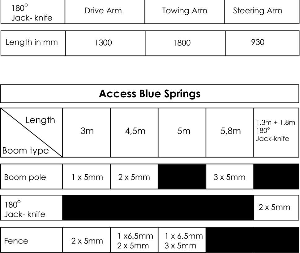
14 Springs and tensioning First ensure that you have the correct springs and number of springs for the pole/arm/fence as per the table at the beginning of this manual. If needed the spring tension can be adjusted with the boom in the raised position (only). Do this by adjusting nuts (A) Ensure the springs rest in the slots of the spring mounting rods.

15 Using the manual maneuver To raise or lower the boom manually, turn the manual maneuver crank at the base of the electric motor as shown here. This would be used to test the spring tension. The boom should move with the same degree of resistance either up or down.


16 Gaining access to the electronics To access the control card remove the controller box from its mounting, by sliding it up and then forward away from the side. The entire control box can now be removed from the box. Remove the cover by unscrewing the four cover screws.

17 PRG JUMPER ON: TRIGGER TO OPEN TRIGGER TO CLOSE TRIGGER WHILE OPENING WILL STOP THE POLE, TRIGGER AGAIN TO CLOSE TRIGGER WHILE CLOSING WILL REVERSE THE POLE DIRECTION OFF: TRIGGER TO OPEN IF NO BEAM INPUT IS ACTIVATED, THE POLE WILL CLOSE AFTER 20 SECONDS IF THE BEAM INPUT IS ACTIVATED, THE POLE WILL CLOSE AFTER 2 SECONDS. IF THE BUTTON INPUT IS MADE WHILE THE POLE IS IN THE OPEN POSITION THE 20 SECOND COUNT WILL RESTART. IF THE BUTTON INPUT IS MADE WHILE THE POLE IS CLOSING THE POLE WILL REVERSE AND THE 20 SECOND COUNTER WILL RESTART. IF BEAM INPUT IS ACTIVATED THE POLE WILL CLOSE AFTER 2 SECONDS.
18 Wiring of the AC1U/Blue boom (N/O Limit) Control card Vac Live input Vac Neutral input 3. Not used 4. Capacitor white and motor Brown 5. Motor Green 6. Capacitor white and motor Blue 7. Fan 8. Fan 9. Common output Vdc 0,8A Aux output 11. Common output (with wire link to Safety presence loop/ir Beam input remove link when installing beams or loop) 12. Safety presence loop/ir Beam input (Linked to common remove link when installing beams or loop) (N/C) 13. Closed Limit input Blue (N/O) 14. Common output 15. Open Limit input Brown (N/O) 16. Not Used 17. Common output 18. Button trigger input (N/O) 19. Status LED Cathode output 20. Status LED Anode output In the case of a bi-directional entry and exit point using a free exit loop, connect the common of the detector relay to the closed limit input. This prevents the car from stopping the boom from lowering when the car passes over the loop.
19 WARRANTY: All goods manufactured by G&C Electronics cc T/A ET Systems carry a 12 month factory warranty from date of invoice. All goods are warranted to be free of faulty components and manufacturing defects. Faulty goods will be repaired or replaced at the sole discretion of ET Systems free of charge. This warranty is subject to the goods being returned to the premises of ET Systems. The carriage of goods is for the customers account. This warranty is only valid if the correct installation and application of goods, as laid out in the applicable documentation accompanying said goods, is adhered to. All warranty claims must be accompanied by the original invoice. All claims made by the end user must be directed to their respective service provider/installer. The following conditions will disqualify this product from the warranty as laid out above. These conditions are non-negotiable. Any unauthorized non-manufacturer modifications to the product or components thereof.
Automatic Garage Door Operator
 Automatic Garage Door Operator support@et.co.za ET Systems (PTY) Ltd 15 Nelson Rd, Observatory, Cape Town, South Africa www.et.co.za Technical specifications may change without prior notice. All goods
ET BLUE-ROLL Domestic type roll-up garage door operator. Installation manual Revision Oct
 ET BLUE-ROLL Domestic type roll-up garage door operator Installation manual Revision Oct.08.002 support@et.co.za Technical specifications may change without prior notice. All goods are subject to the standard
DTS SECURITY P.O.BOX 3399 EDENVALE 1610 Base plate-mounting instructions TELEPHONE
 DTS ECO 500 SLIDING GATE MOTOR INSTALLATION MANUAL DTS SECURITY P.O.BOX 3399 EDENVALE 1610 Base plate-mounting instructions TELEPHONE 086 1000 387 Spartan +2711 392 5540 (H/O) Pretoria +2712 361 5528 Alberton
UMPETHA U / Domestic sliding gate operator by ET SYSTEMS. USER GUIDE
 Domestic sliding gate operator by ET SYSTEMS. USER GUIDE 1 Table of contents Page Description 3 Safety obligations and general warnings M anual ov erride 3 How to mov e the gate by hand. Manual override
Installer Instructions
 (400mm stroke length) Plus For dimensions of the 300mm model please contact us directly Installer Instructions 1 Page Table of contents Category Introduction 3 Safety obligations and general warnings 4
TEL: G&C Electronics CC E. T.
 TEL: +27 21 448 6774 G&C Electronics CC FAX: +27 21 447 7794 E. T. CK 89/31531/23 E-mail : etsystems@icon.co.za Internet: www.et.co.za 15 Nelson Road P.O. Box 34524 Observatory Groote Schuur Cape Town
DTS 412/512/624 SLIDING GATE MOTOR INSTALLATION MANUAL
 DTS 412/512/624 SLIDING GATE MOTOR INSTALLATION MANUAL DTS SECURITY P.O.BOX 3399 EDENVALE 1610 TELEPHONE 086 1000 387 Base plate-mounting instructions Alberton 011 907 8846 Centurion 012 653 4434 Edenvale
MODEL D-WBG Wishbone Arm Barrier Gate Operator
 INSTALLATION AND OWNER S MANUAL MODEL D-WBG Wishbone Arm Barrier Gate Operator UL 325 and UL 991 Listed WITH NITRO BOARD (SEE SUPPLEMENTAL MANUAL) Serial #: Date Installed: Your Dealer: READ THIS MANUAL
ALVARADO (1029 mm) 25 (635 mm) 36.5 (927.1 mm)
 25 (635 mm) 36.5 (927.1 mm)") ALVARADO EDCX Bullnose Waist High Turnstile Technical Specifications Dimensions Unit Height: Unit Width: Unit Depth: 40.5 (1029 mm) 25 (635 mm) 36.5 (927.1 mm) Materials Cabinet: Formed and welded 14 gauge
ALVARADO EDCX Bullnose Waist High Turnstile Technical Specifications Dimensions Unit Height: Unit Width: Unit Depth: 40.5 (1029 mm) 25 (635 mm) 36.5 (927.1 mm) Materials Cabinet: Formed and welded 14 gauge
(1032 mm) 30.5 (775 mm) 44 ( mm)
 30.5 (775 mm) 44 ( mm)") ALVARADO EDCX-EK Waist High Turnstile Technical Specifications Dimensions Unit Height: Unit Width: Unit Depth: 40.625 (1032 mm) 30.5 (775 mm) 44 (1117.6 mm) Materials Cabinet: Formed and welded 14 gauge
ALVARADO EDCX-EK Waist High Turnstile Technical Specifications Dimensions Unit Height: Unit Width: Unit Depth: 40.625 (1032 mm) 30.5 (775 mm) 44 (1117.6 mm) Materials Cabinet: Formed and welded 14 gauge
CENTOR TRAFFIC BARRIER
 CENTOR TRAFFIC BARRIER Product Code: CP72CENTOR INSTALLATION MANUAL Latest Revision: 15.03.2007 Document Ref.: 1123.D.01.0002_8 Table of Contents Introduction...................................................................
R3R5 quick setup guide ROTARY SWING GATE OPERATOR
 R3R5 quick setup guide TM TM ROTARY SWING GATE OPERATOR 1 REQUIRED TOOLS & EQUIPMENT Check that you have all the tools required. (IM page 1) 3 SITE CONSIDERATIONS Check for the safety and suitability of
MODEL D-SBG Single Arm Barrier Gate Operator
 INSTALLATION AND OWNER S MANUAL MODEL D-SBG Single Arm Barrier Gate Operator UL 325 and UL 991 Listed WITH NITRO BOARD (SEE SUPPLEMENTAL MANUAL) Serial #: Date Installed: Your Dealer: READ THIS MANUAL
Domestic sliding gate operator by ET SYSTEMS. Installer instructions
 Domestic sliding gate operator by ET SYSTEMS. Installer instructions 1 Table of contents Page Category Introduction 3 Safety obligations and general warnings 4 Identification of components 5 Technical
MODEL WBG WISHBONE BARRIER GATE OPERATOR
 TABLE OF CONTENTS MODEL WBG WISHBONE BARRIER GATE OPERATOR Important Safety Information.....3 System Designer Safety Instructions.......4 Installer Safety Instructions........ 5 End User Safety Warnings...-
PARQUBE FIRST LINE MAINTENANCE MANUAL
 PARQUBE FIRST LINE MAINTENANCE MANUAL Site Maintenance Procedures This document contains important information pertaining to the servicing of a PARQUBE site as well as procedures for logging calls, ordering
Index. COMPACT domestic gate operator
 COMPACT domestic gate operator Index Introduction. 3. General motor layout 4. General site layout 5. Terms and definitions. 6.. Site evaluation. 6. Gate evaluation 7. Removing the lid 8. Placing the gate
Typical applications are the control of barriers/booms in the parking and access control environments.
 Barrier Logic Model - BL110B The BL110B is a barrier logic unit which has been developed to control barriers using magnetic motors with ease of installation. The BL110B accepts inputs from card readers
PowerMaster MODEL MBG. Installation Manual U L R UL 325 AND UL 991 LISTED MEDIUM DUTY BARRIER GATE OPERATOR TABLE OF CONTENTS
 PowerMaster TABLE OF CONTENTS MODEL MBG MEDIUM DUTY BARRIER GATE OPERATOR Important Safety Information...... 3 System Designer Safety Instructions.......4 Installer Safety Instructions....... 5 Installation
INSTALLATION GUIDE. For Carrier/Bryant Residential Power Systems
 INSTALLATION GUIDE For Carrier/Bryant Residential Power Systems For 100 Amp Automatic Transfer Switch/Load Center Model: KGATX0116100 16 circuit installed with 16kW generators. This Automatic Transfer
Roll Up Door Operator
 INSTRUCTIONS & OWNERS MANUAL Roll Up Door Operator 2 INDEX Preparation before installation 4. Terms and definitions 5. Pictures & names of parts 6. Mounting the weight bar 7. Installing the operator 7.
Instruction Manual for the. E-SL 450 Series
 Instruction Manual for the E-SL 450 Series Estate Slide Summary of Functions The Estate Slide is only to be used for vehicular Slide gates in a Class I setting. Class I: A vehicular gate opener (or system)
ACSI MODEL 1440 POWER SUPPLY INSTALLATION INSTRUCTIONS
 II 1400-8 Features: ACSI MODEL 1440 POWER SUPPLY INSTALLATION INSTRUCTIONS Filtered/Regulated 24 Volts DC Up to Full 2 Amps Load Capacity Class 2 Rated Outputs Overload, Over Voltage, and Short Circuit
#366. Gate Operator Pre-Installation and Site Planning. Introduction
 Gate Operator Pre-Installation and Site Planning Introduction Although each manufacturer s equipment has unique design characteristics and functions, gate operators are somewhat similar in many installation
12V PROGRAMMABLE POWER OUT
 Page 1 ACCESSORIES STARTER IGNITION BATTERY WIRES SIDE VIEW BLUE RED YELLOW 30 A 10 A BLUE / WHITE YELLOW WHITE / BLUE WHITE / DOOR TRIGGER See opt. 16 DOOR TRIGGER (input positive) See opt. 16 PARKING
INSTALLER S MANUAL AUTOMATIC GARAGE DOOR OPENER
 take control of your world INSTALLER S MANUAL AUTOMATIC GARAGE DOOR OPENER REVISED DATE: March 2004 INDEX 1. WHAT S IN THE BOX A list of contents you will receive with this product and technical specifications
TMT Boxer 24v slider motor installation notes from EasyGate
 TMT Boxer 24v slider motor installation notes from EasyGate Install Physical Gate Stops Physical Gate Stops MUST be installed at each end of your gate. If the Limit Switch on the boxer motor fails to stop
DOMESTIC SLIDING GATE OPERATOR
 D Turbo Pocket mechanical installation guide TM DOMESTIC SLIDING GATE OPERATOR This guide is designed specifically for installers who are familiar with the installation of standard sliding gate motors,
JBI Docupunch P33 Automatic Punch
 JBI Docupunch P33 Automatic Punch Instruction Manual Provided By http://www.mybinding.com http://www.mybindingblog.com TABLE OF CONTENTS SECTION I: INSTALLATION & TESTING: 1) Uncrating, Inspection & removal
Unpack. Left Handing (L) the Operator. StrongArmPark DC Breakaway Bracket Installation Video
 the Operator. StrongArmPark DC Breakaway Bracket Installation Video") DC Left Handing (L) Standard. Factory ships left handing operator. NOTE: If your site requires right handing, place the order with your distributor as a StrongArmPark DC with right handing. Handing changes
DC Left Handing (L) Standard. Factory ships left handing operator. NOTE: If your site requires right handing, place the order with your distributor as a StrongArmPark DC with right handing. Handing changes
62 Deck Idler Kit High Speed
 Part No. 00 FORM NO. -899 6 Deck Idler Kit High Speed For Model 70 Serial No. 99000 to 99000 For Model 7 Serial No. 9900 to 99000 INSTALLATION INSTRUCTIONS Loose Parts Note: Use the chart below to identify
91 (2311 mm) (1581mm) (1375 mm)
 (1581mm) (1375 mm)") ALVARADO MSTX Maximum Security Turnstile Technical Specifications Dimensions Unit Height: Unit Width: Unit Depth: 91 (2311 mm) 62.25 (1581mm) 54.125 (1375 mm) Materials Yoke: (Curved Section) Yoke Guard
ALVARADO MSTX Maximum Security Turnstile Technical Specifications Dimensions Unit Height: Unit Width: Unit Depth: 91 (2311 mm) 62.25 (1581mm) 54.125 (1375 mm) Materials Yoke: (Curved Section) Yoke Guard
Long-Range Barrier Sensors
 Long-Range Barrier Sensors Manual Model # of Beams Length E-9626-2B190Q 2 pairs 26 (66cm) E-9643-4B190Q 4 pairs 43 (109cm) E-9661-6B190Q 6 pairs 61 (155cm) E-9679-8B190Q 8 pairs 79 (201cm) 4 Different
491 Harness Installation Kit
 491 Harness Kit 002-0759-00 Kit Components: Qty Harness Assy... 1 Wire Clip... 2 Wire Tie (7 1/2 )... 5 Wire Tie (7 1/4 )... 4 Instruction... 1 Remove Back Cover Warning Disconnect Power before removing
Midmark Light Install: L/R mounted on Ultra Chair
 Midmark Install: L/R mounted on Ultra Chair warning Equipment is not suitable for use in the presence of a flammable anesthetic mixture. Applies to Models: 153914 (-002) 153915 (-002) Language of origin:
AccuSpark. Fitting and Information Guide For. Modules Distributors coils Tools. Modern Ignition for Classic cars
 AccuSpark Modern Ignition for Classic cars Fitting and Information Guide For Modules Distributors coils Tools www.accuspark.co.uk 1 Before fitting AccuSpark Distributors AccuSpark electronic ignition kit.
Gate Operators, Inc. Model 7100UL Residential & Medium Duty Commercial Slide Gate Operator INSTALLATION MANUAL
 Gate Operators, Inc. Model 7100UL Residential & Medium Duty Commercial Slide Gate Operator INSTALLATION MANUAL 10-04-00 CONTENTS Safety Precautions... 2 Applications... 3 Pre-Installation Checklist...
10260 Retrofit to 10260A Non-Contact Sensor Instructions Kits through -512
 10260 Retrofit to 10260A Non-Contact Sensor Instructions Kits 51404974-501 through -512 Document Number Form: 62-86-33-16D Effective: 3-1-01 Supersedes: 11-00 Summary Retrofitting your 10260 actuator from
SLIDING GATE OPENER USER MANUAL
 is600 / is900solar24 SLIDING GATE OPENER USER MANUAL Bluetooth charge monitoring app INDEX 1.1 GENERAL SAFETY PRECAUTION 1.2 KIT CONTENTS.. P.1 P.2 1.3 DIMENSION... P.3 1.4 TECHNICAL FEATURES P.4 1.5 INSTALLATION
ET-500 AUTOMATIC SLIDE GATE MOTOR INSTALLER S MANUAL FOR ACDC500 & DC500 MODELS
 ET-500 AUTOMATIC SLIDE GATE MOTOR INSTALLER S MANUAL FOR ACDC500 & DC500 MODELS take control of your world REVISED DATE: May 2004 INDEX 1. WHAT S IN THE BOX A list of contents you will receive with this
INSTALLATION INSTRUCTION 88088
 INSTALLATION INSTRUCTION 88088 For Rancho Suspension Systems RS6588 & RS6589: FORD F-150 READ ALL INSTRUCTIONS THOROUGHLY FROM START TO FINISH BEFORE BEGINNING INSTALLATION Rev B IMPORTANT NOTES! WARNING:
INSTALLATION INSTRUCTIONS Air Spring Kit Ford F-150 4WD IMPORTANT NOTES
 INSTALLATION INSTRUCTIONS 6154 Air Spring Kit 2004+ Ford F-150 4WD Thank you for purchasing a quality Hellwig Product. PLEASE READ THIS INSTRUCTION SHEET COMPLETELY BEFORE STARTING YOUR INSTALLATION IMPORTANT
Installation and Service Manual
 RESIDENTIAL PLATFORM LIFTS RPL400 / RPL600 Installation and Service Manual WARNING! STRICT ADHERENCE TO THESE INSTALLATION INSTRUCTIONS IS REQUIRED to promote the safety of those installing this product,
Rotary Dropper. Universal Friction Feeder. Mechanical Components Guide
 Rotary Dropper Universal Friction Feeder Part Number: 00900424/Rev. A (November, 2002) 2002 Streamfeeder, LLC. All rights reserved. No part of this publication may be reproduced, photocopied, stored on
HercuLine 2000 Series Gear Kit Replacement Instructions
 HercuLine 2000 Series Gear Kit Replacement Instructions 51452443-501 Document Information Form: 62-86-33-35 Effective: 5/04 Supersedes: None Summary This kit contains all the gears, idler shafts and hardware
BEAMER Tilt Beam Sensor
 User s Manual BEAMER Tilt Beam Sensor Serial No. 140 Chestnut Street San Francisco, CA 94111 Phone: 415 364 3200 Fax: 415 861 1448 www.geomechanics.com CAUTION: Never measure the sensor inside your Beamer
Midi Traffic Light installation manual TRAFFIC CONTROL ACCESSORIES
 Midi Traffic Light installation manual TRAFFIC CONTROL ACCESSORIES Company Profile 1986 1990 1995 1999 Centurion Systems today In-house R & D development team Manufacture to international quality standard
ENCORE 52" X-TREME. 2-BAG GRASS CATCHER for units w/ S/N and above ASSEMBLY AND PARTS DIAGRAMS
 ENCORE 52" X-TREME 2-BAG GRASS CATCHER for units w/ S/N 53138 and above ASSEMBLY AND PARTS DIAGRAMS Notes: ASSEMBLY INSTRUCTION Figure 1 Using 1/2" wrench, remove the discharge cover and the RH deck belt
Saimatic Aster Gate Operator, Automation System Manual. 110V or 220V
 Saimatic Aster Gate Operator, Automation System Manual 110V or 220V 1 WARNINGS AND PRECAUTIONS Read the instructions carefully before installing the gate automation system. Keep these instructions for
Instruction Manual. Model RAM-1000 UL & RAM-5500 UL For Class I, II, III, IV Vehicular Gate Operators. No Rev
 Rev 060202 Instruction Manual Model RAM-1000 UL & RAM-5500 UL For Class I, II, III, IV Vehicular Gate Operators C No. 545327 US TABLE OF CONTENTS Important Safety Requirements & Instructions.......................................1,2
Emergency lighting units EM powerled
 EM power EM power SEFTEST 1 2 W Combined emergency lighting Driver 1 4 W Product description Emergency lighting Driver with self-test function For self-contained emergency lighting SEV for output voltage
IMI vibration switch USER MANUAL INSTALLATION - OPERATION - MAINTENANCE
 USER MANUAL IMI vibration switch INSTALLATION - OPERATION - MAINTENANCE Z0929039_A ISSUED 03/2017 READ AND UNDERSTAND THIS MANUAL PRIOR TO OPERATING OR SERVICING THIS PRODUCT. contents Overview General
650 Series Cargo Van Lift Mounting Instructions Ford Transit (Standard Roof) 2015-Present
 2015-Present") TOMMY GATE OWNER'S / OPERATOR'S MANUAL 650 Series 650 LB Capacity 650 Series Cargo Van Lift Mounting Instructions Ford Transit (Standard Roof) 2015-Present Installing the Base Plate 1. Examine the interior
TOMMY GATE OWNER'S / OPERATOR'S MANUAL 650 Series 650 LB Capacity 650 Series Cargo Van Lift Mounting Instructions Ford Transit (Standard Roof) 2015-Present Installing the Base Plate 1. Examine the interior
Linear Actuator Swing Gate Operator Installation Manual Model # LA405-24
 Linear Actuator Swing Gate Operator Installation Manual Model # LA405-24 2 Contents Contents Product Information and Specs. 3 Mechanical 3 Electrical, Line Connections 3 Electrical, Control Connections
SECURITY DOOR CONTROLS
 CR4 FOUR STATION CONTROL MODULE The CR4 module operates on 12V or 24V DC and provides control of four (4) stations. Each CR4 station accepts a Dry () trigger input and provides one (1) Fused 2 Amp SPDT
Installation Manual. For. PWC 3000 Boat Lifts
 Installation Manual For PWC 3000 Boat Lifts Page 2 Safety Precautions 1. Your boat lift is a heavy duty piece of equipment. It is important that all persons that may operate this unit have read and understood
650 Series Cargo Van Lift Mounting Instructions Fullsize Ford 1992-Present
 TOMMY GATE OWNER'S / OPERATOR'S MANUAL 650 Series 650 LB Capacity 650 Series Cargo Van Lift Mounting Instructions Fullsize Ford 1992-Present Installing the Base Plate 1. Examine the interior and exterior
Types of Doors that can be automated using the digi.one: Sectional overhead doors, single/double, steel or timber. Tip up doors, steel or timber.
 Types of Doors that can be automated using the digi.one: Sectional overhead doors, single/double, steel or timber. Tip up doors, steel or timber. Page 1 1. Features Microprocessor based control system
Hunter Automatics HA-8. Installation Manual
 Hunter Automatics HA-8 Installation Manual WARNING TO REDUCE RISK OF INJURY 1. READ AND FOLLOW ALL INSTALLATION INSTRUCTIONS CAREFULLY. FAILURE TO DO SO MAY RESULT IN PERSONAL INJURY OR PROPERTY DAMAGE
Series AA Roller Door
 Series AA Roller Door Installation Instructions TAUREAN DOOR SYSTEMS Phone (03) 9721-8366 www.taureands.com.au Extreme safety warning. Safe practices must be observed when working at heights, lifting roller
Series B Roller Door. Installation Instructions. TAUREAN DOOR SYSTEMS Phone (03)
") Series B Roller Door Installation Instructions TAUREAN DOOR SYSTEMS Phone (03) 9721-8366 www.taureands.com.au Extreme safety warning. Safe practices must be observed when working at heights, lifting roller
Series B Roller Door Installation Instructions TAUREAN DOOR SYSTEMS Phone (03) 9721-8366 www.taureands.com.au Extreme safety warning. Safe practices must be observed when working at heights, lifting roller
Cabinet Free Universal Assist Lifter Instructions
 PART LIST 1 @ Left Undermount Bracket 1 @ Right Undermount Bracket 2 @ 1-5/16 Pivot Arm 2 @ 1-1/8 Bent Arms w/ Foams 2 @ M8 Bolt 1 @ 1-5/16 Coupler 2 @ Gas Shocks w/ Sliding Cylinder Mount 2 @ 3-1/4 x
F ERNI K I T THE FERNI-S KIT CONSISTS OF:
 CAME UNITED KINGDOM LTD ORCHARD PARK INDUSTRIAL ESTATE TOWN STREET, SANDIACRE, NOTTINGHAM, NG10 5BP TEL: 0115 921 0430 FAX: 0115 921 0431 INTERNET - www.cameuk.com E-MAIL - enquiries@cameuk.com TECHNICAL
Emergency lighting units EM powerled
 EM power EM power SEFTEST 1 2 W Combined emergency lighting Driver 1 4 W Product description Emergency lighting Driver with self-test function For self-contained emergency lighting SEV for output voltage
Quarter Master Series 94 Actuator
 Quarter Master Series 94 Actuator Installation, Operation and Maintenance Manual Assembly Series 94 Manual Rev V 9/5/13 Page 1 of 12 Table of Contents Series 94 Electric Actuator Introduction... 3 Description...
PLASTIC FOLDING ARM KIT This kit is designed for the 1600 model barrier gate operators only. Recommended for low headroom applications.
 PLASTIC FOLDING ARM KIT This kit is designed for the 600 model barrier gate operators only. Recommended for low headroom applications. Kit Includes: Plastic Arms Attachment Assembly Clamp Locking Turnbuckle
Barrier Gate Manual. (DZX2.1 Control Board) (The third version) (Pictures for reference only, the product prevail in kind)
 (The third version) (Pictures for reference only, the product prevail in kind)") Barrier Gate Manual (DZX2. Control Board) (The third version) (Pictures for reference only, the product prevail in kind) Contents. Brief Introduction... 2. Functions and Features... 3. Technical Data...2
Barrier Gate Manual (DZX2. Control Board) (The third version) (Pictures for reference only, the product prevail in kind) Contents. Brief Introduction... 2. Functions and Features... 3. Technical Data...2
Site Maintenance Procedures Revision 3
 Site Maintenance Procedures Revision 3 1 Site Maintenance Procedures This document contains important information pertaining to the servicing of a HUB site as well as procedures for logging calls, ordering
12V DC MOTORISED OPENER FOR SWING GATES Section Table of Contents Page
 12V DC MOTORISED OPENER FOR SWING GATES Section Table of Contents Page 1 Introduction 2 2 Warnings 4 3 Technical Specifications 5 4 Positioning 6 5 Wiring Diagram 7 6 Standard Installation Kit 8 7 Installation
INSTALLATION AND OWNERS MANUAL
 SLIDE GATE OPERATORS: COMPACT 300 COMPACT 500 SOLO CONDO CONDO AC/DC SWING GATE OPERATORS: DURASWING GARAGE DOOR OPERATORS: LAZER SECTIONAL LAZER ROLL UP LAZER VERTICAL ROLL UP LAZER TIP UP PROUD MANUFACTURERS
FULL HEIGHT ALUMINUM TURNSTILE DOUBLE UNIT AT-FAL SERIES I N STALLATION AND O P E RATING I N STRUCTIONS
 FULL HEIGHT ALUMINUM TURNSTILE DOUBLE UNIT AT-FAL SERIES I N STALLATION AND O P E RATING I N STRUCTIONS CONTENTS 1. SITE PREPARATION 2. EXPLODED VIEW DRAWING 3. UNPACKING 4. SPECIFICATIONS 5. INSTALLATION
INSTALLATION INSTRUCTIONS
 Equipped with AEM Dryflow Filter No Oil Required! INSTALLATION INSTRUCTIONS PART NUMBER: 21-8028 2010 CHEVROLET Camaro V6-3.6L SEE * NOTE * NOTE: Legal in California only for racing vehicles which may
Railway. assembly instructions. data and power solution. model# RAIL-LINEAR model# RAIL-90 model# RAIL-BULLPEN model# RAIL-3WAY model# RAIL-4WAY
 assembly instructions Railway data and power solution model# RAIL-LINEAR model# RAIL-90 model# RAIL-BULLPEN model# RAIL-3WAY model# RAIL-4WAY linear 90 bullpen 3-way 4-way Components and tools Safety instructions/warning
WARNING: HARDWARE PACK (A ) DO NOT INSTALL if the truck has been lifted and the stock jounce bumper spacers are not on the vehicle.
 DO NOT INSTALL if the truck has been lifted and the stock jounce bumper spacers are not on the vehicle.") DO NOT INSTALL if the truck has been lifted and the stock jounce bumper spacers are not on the vehicle. 2550 WARNING: Do not inflate this assembly when it is unrestricted. The assembly must be restricted
DO NOT INSTALL if the truck has been lifted and the stock jounce bumper spacers are not on the vehicle. 2550 WARNING: Do not inflate this assembly when it is unrestricted. The assembly must be restricted
DTS SLIDING GATE MOTOR INSTALLATION MANUAL. DTS 600 Elite with SL150 PCB DTS SECURITY P.O.BOX 3399 EDENVALE 1610 TELEPHONE
 DTS SLIDING GATE MOTOR INSTALLATION MANUAL DTS 600 Elite with SL150 PCB DTS SECURITY P.O.BOX 3399 Base plate-mounting EDENVALE instructions 1610 TELEPHONE 086 1000 387 Spartan +2711 392 5540 (H/O) Pretoria
This Automatic Transfer Switch with built-in Load Center includes an Express Install Kit.
 This Automatic Transfer Switch with built-in Load Center includes an Express Install Kit. Saves on installation time and cost, in many cases up to 50% compared to traditional transfer switch installations.
CRUSH HAZARD: CHILD SAFETY HAZARD:
 1 This Operations Manual contains important instructions, warnings, and safety procedures that must be understood BEFORE assembling or using the M.I.N.E. Trapping System. Failure to review and understand
Grass Catcher. Instructional / Parts Manual Part Number: January ( & ) & Drive Kits ( , , )
 & Drive Kits ( , , )") Grass Catcher Instructional / Parts Manual Part Number: January 200 5020 ( 507 & 5026 ) & Drive Kits ( 52030, 5203, 52032) Table of Contents Z RIDER GRASS CATCHER TWO PACKAGED ITEMS LIST 507 BLOWER ASSEMBLY
Grass Catcher Instructional / Parts Manual Part Number: January 200 5020 ( 507 & 5026 ) & Drive Kits ( 52030, 5203, 52032) Table of Contents Z RIDER GRASS CATCHER TWO PACKAGED ITEMS LIST 507 BLOWER ASSEMBLY
INSTALLATION M ANUAL
 INSTALLATION MANUAL Table of Contents UL Listings Installing the Warning Sign / Precautions Methods of Installation / Compact Installation Mounting the Secondary Entrapment / Welding Gate Arn Mounting
MST. model. alvaradomfg.com
 alvaradomfg.com FULL HEIGHT TURNSTILES model The is the most trusted, secure and reliable full height turnstile available. It is installed in thousands of locations around the world and offers key product
DODGE DAKOTA 3 KIT INSTALLATION INSTRUCTIONS KIT# 60043
 DODGE DAKOTA 3 KIT INSTALLATION INSTRUCTIONS 2000-2002 KIT# 60043 Installation of a Performance Automotive Group body lift kit will change the vehicle s center of gravity and handling characteristics both
INDEX INTRODUCTION.P2 WARRANTY..P2 LEGAL REQUIREMENTS AND WARNINGS...P3 RECOMMENDED TOOLS...P3 TERMS AND DEFINITIONS. P4 MOTOR LAYOUT...
 INDEX INTRODUCTION.P2 WARRANTY..P2 LEGAL REQUIREMENTS AND WARNINGS...P3 RECOMMENDED TOOLS...P3 TERMS AND DEFINITIONS. P4 MOTOR LAYOUT...P5 SITE EVALUATION...P6 GATE EVALUATION. P7 START UP FORCE.P8 REMOVING
INSTALLATION INSTRUCTION 88092
 INSTALLATION INSTRUCTION 88092 FOR RANCHO SUSPENSION SYSTEM RS6592: NISSAN XTERRA & 2WD FRONTIER READ ALL INSTRUCTIONS THOROUGHLY FROM START TO FINISH BEFORE BEGINNING INSTALLATION Rev C IMPORTANT NOTES!
OPERATING INSTRUCTIONS PLEASE READ CAREFULLY
 OPERATING INSTRUCTIONS PLEASE READ CAREFULLY 925-0330 Rev 0 0416 TABLE OF CONTENTS SAFETY SUMMARY... 3 SPECIFICATIONS... 4 1.0 INTRODUCTION/DESCRIPTION.... 5 2.0 LOCATION AND MOUNTING... 5 3.0 CONNECTIONS
InstaTrike. Installation Manual. Yamaha Virago 750/1100
 InstaTrike By Installation Manual Yamaha Virago 750/1100 Limited Warranty TOW-PAC, INC. warrants to the first end user purchaser that this product InstaTrike when purchased will be free from defective
THT-100 ASTG THT-100 ASTG2 Security Turnstiles. Installation, Operation and Maintenance Manual. 1 Rev
 THT-100 ASTG THT-100 ASTG2 Security Turnstiles Installation, Operation and Maintenance Manual 1 Rev 0103.01 CONTENTS IMPORTANT SAFEGUARDS........................................3 SAFETY PRECAUTIONS...........................................3
Contents. Section 5: Adjustments Ball Detect Adjustment Transport Band Tension Adjustment
 Contents Section 5: Adjustments... 5-3 1. Ball Detect Adjustment... 5-3 2. Transport Band Tension Adjustment... 5-5 3. Transport Band Drive Belt Tension Adjustment... 5-7 4. Ball Cushion Adjustment...
Emergency lighting units EM powerled
 EM power EM power PRO EZ-3, 1 2 W Combined emergency lighting Driver 1 4 W Product description Emergency lighting Driver with I interface and automatic test function For self-contained emergency lighting
E-SL 450BD Series INSTRUCTION MANUAL WARNING USER DRIVEN MANUAL*
 USER DRIVEN MANUAL* Any feedback, changes, or advice we are glad to hear it. Please contact us at support@estateswing.com WARNING Read all instructions before beginning installation or use of this gate
Read and understand all instructions and warnings prior to installation of product and operation of vehicle.
 #F9378 Installation Instructions 1998-2000 Ford Ranger 3" Body Lift Kit Read and understand all instructions and warnings prior to installation of product and operation of vehicle. Zone Offroad Products
INSTALLATION INSTRUCTIONS DRAWERS #240
 INSTALLATION INSTRUCTIONS DRAWERS #240 Please read and fill out the enclosed warranty registration card to activate your warranty. SHIPMENT CONTENTS #1 Lid #2 Rear #3 Left side panel #4 Right side panel
FRAME MOUNTED SPRING LOADED CONSERVATION COULTER
 FRAME MOUNTED SPRING LOADED CONSERVATION COULTER MODEL 2991 AND 2999 SET-UP & PARTS CATALOG YETTER MANUFACTURING CO. FOUNDED 1930 Colchester, IL 62326-0358 Toll free: 800/447-5777 309/776-3222 (Fax) Website:
WARNING! THIS PRODUCT IS
 HOLLYWOOD R A C K S www.hollywoodracks.com Assembly and Installation instructions for model numbers: Road Runner 3 Series HR300-3-bike model for 2 receiver, class 2 or higher HR310-3 bike model for 1 ¼
Last Revision: 30JN THRU 1979 C3 CORVETTE STANDARD (NON-ADJUSTABLE) STEERING COLUMN DISASSEMBLY & REPAIR INSTRUCTIONS PAPER #2
 STEERING COLUMN DISASSEMBLY & REPAIR INSTRUCTIONS PAPER #2") Last Revision: 30JN2007 1969 THRU 1979 C3 CORVETTE STANDARD (NON-ADJUSTABLE) STEERING COLUMN DISASSEMBLY & REPAIR INSTRUCTIONS PAPER #2 Disassembly and Repair Instructions Addressed in this Paper Degree
Last Revision: 30JN2007 1969 THRU 1979 C3 CORVETTE STANDARD (NON-ADJUSTABLE) STEERING COLUMN DISASSEMBLY & REPAIR INSTRUCTIONS PAPER #2 Disassembly and Repair Instructions Addressed in this Paper Degree
Sliding Gate Operator User's Manual
 Sliding Gate Operator User's Manual SL600AC. Products introduction Please read the instructions carefully before proceeding. MCU is supplied to control the gate operator. Keypad / single button interface.
Installation Manual. For. Alumavator and Platinum. Vertical Installation. Elevator Boat Lifts
 Installation Manual For Alumavator and Platinum Vertical Installation Elevator Boat Lifts Page 2 Safety Precautions 1. Your boat lift is a heavy duty piece of equipment. It is important that all persons
2904 Power Supply Installation Instructions I-EA00041
 FEATURES Controls an opening with electrified locking device and automatic door operator Separate inputs for activation switch on entry and exit sides of opening Separate 24 VDC outputs for fail safe and
EDC-E. Waist HIGH Turnstiles. alvaradomfg.com
 Waist HIGH Turnstiles alvaradomfg.com Descriptive SPECIFICATIONS The is an extended length cabinet turnstile with extended length turnstile arms. It is a rugged, multi-purpose turnstile used to provide
Read and understand all instructions and warnings prior to installation of system and operation of vehicle.
 102 S. Michigan Ave., Coldwater, MI 49036 Phone: 517-279-2135 Web/live chat: www.bds-suspension.com E-mail: tech@bds-suspension.com Part#: 023620 Product: 6" Suspension System Application: 2009-2012 Ford
INSTRUCTION MANUAL_. Specifications. Electrical.
 308 Industrial Park Road Starkville, MS 39759 USA Ph: (662) 323-9538 FAX: (662) 323-6551 DX-77A 7-Band HF Vertical 10, 12, 15, 17, 20, 30, 40-Meter INSTRUCTION MANUAL_ General Description The "DX-77-A"