Installer Instructions
|
|
|
- Lambert Newman
- 5 years ago
- Views:
Transcription

1 (400mm stroke length) Plus For dimensions of the 300mm model please contact us directly Installer Instructions 1
2 Page Table of contents Category Introduction 3 Safety obligations and general warnings 4 Technical specifications 5 Dimensions 6 Cable requirements Hardware installation 6 Using the manual release 7 Assembling the mounting brackets 8 & 9 Inward swing installation method 10 & 11 Outward swing installation method 12 Control box connections 13 Limit switch and motor wiring for inward swings 14 Limit switch and motor wiring for outward swings 15 Visual setting of the limit switches Motor control programming 16 Using the limit switches and limit configuration tester. 17 Using the motor direction tester. 18 Auto-close time programming 19 Pedestrian opening and auto-close time programming. 20 Delay time programming. 21 Courtesy light on time programming. 22 Safety beam switch type programming. 23 Adjusting the safety obstruction sensing. Receiver programming 24 Master erasing the receiver memory. 25 Learning new remote buttons into the receiver memory. Operating mode selection 26 Standard mode (Start, Stop, Start mode) 26 Simple auto-close mode 27 Condo/Loop mode 27 Delay mode 28 Strike lock mode 28 Magnetic lock mode. Additional features 29 Holiday lock-out 29 Courtesy light functionality 30 Auto-close override/party mode 30 Pedestrian operation Trouble shooting 31 Buzzer indication trouble shooting guide 31 Status LED indication guide 32 Warranty 2
3 WARNING TO THE INSTALLER. GENERAL SAFETY OBLIGATIONS. Caution! It is important for personal safety to follow all the instructions carefully. Incorrect installation or misuse may cause serious personal harm. Keep the instructions in a safe place for future reference. This product was designed and manufactured strictly for the use indicated in this documentation. Any other use not expressly indicated in this documentation, may damage the product and/or be a source of danger. We accept no responsibility due to improper use of this product. Care must be taken not to install this product in an unsafe environment. I.e. near inflammable gases and or fumes. We will not accept responsibility if the principles of good workmanship are disregarded by the installer. The construction of the gate must be sound and automatable. It is the responsibility of the installer to ensure that all mountings to the gate are sufficient to withstand the necessary forces in cases of overload. Before carrying out any work on the product, ensure that the electrical supply is switched off. It is highly recommended that a set of safety infra-red beams be used in conjunction with this product. We accept no responsibility regarding safety and correct operation of the automation if other manufacturer s equipment is added to this product. Do not make any modifications or alterations to this product. It is the responsibility of the installer/ service provider to completely instruct and demonstrate the proper use of this product, especially the emergency override, to the end user. It is also the responsibility of the installer/ service provider to issue all end user documentation, which accompanies this product, to the end user. Ensure that other persons, especially children are clear of the gate and opener before and during operation. Keep remote transmitters away from children to prevent accidental activation of the system. The end user should refrain from attempting to make any repairs or adjustments to the system and should contact professional qualified assistance timorously. Anything other than expressly provided for in these instructions is not permitted. The electrical supply to this product must comply with the local electrical code of practice and any electrical work must be carried out by a qualified electrician. Over and above the recommendation to use safety infra-red beams with this product it is mandatory to ensure sufficient beam sets are installed and are in proper working condition when using the automatic closing feature. 3
4 Technical specifications POWER SUPPLY AT GATE 29V AC POWER CONSUMPTION < 30W (250Vac) MOTOR VOLTAGE 24V DC MAX. DRIVE ARM SPEED 16mm/sec OPERATIONS PER DAY 100 OPERATING TEMPERATURE RANGE -10 / +50 C ANTI-CRUSHING SAFETY SENSING ELECTRONIC MAXIMUM GATE LEAF LENGTH 2.5 meters MAXIMUM GATE MASS 200kg AUXILIARY OUTPUT FOR ANCILLIARIES (Peak) 12V DC at 300mA Automatic overload protection RATED BATTERY CHARGING VOLTAGE 27.5V DC BUILT IN RECEIVER FORMAT Keeloq Rolling code RECEIVER FREQUENCY MHz 4
5 1100mm 660mm 380mm ET 90 BLUE PLUS 2012/007 5
6 WIRING REQUIREMENTS A Courtesy Light 2 + earth 1mm (3 Amp max load) B Motor 1 and 2 wiring 2 x 2.5mm (Motor) and 3 x 0.5mm (Limits) C Infra-red safety beams TX 2 x 0.5mm D Infra-red safety beams RX 4 x 0.5mm E Triggers and status LED to and from house 0.5mm x 2 LED, 0.5mm x 1 Common, 0.5mm x 1 Button trigger, 0.5mm x 1 Pedestrian trigger. F Vac supply from house 2 + earth 2.5mm USING THE MANUAL RELEASE Ensure the rubber cover is returned and in place when done using the manual release. 6
7 ASSEMBLING THE MOUNTING BRACKETS Motor mounting bracket PK-0002 PK-0003 PK-0002 Gate mounting bracket PK-0002 PK
8 INWARD SWING INSTALLATION METHOD A) Using a chalk line project a line through the centre of each hinge as shown here. This is the origin line. B) Using the template, supplied, or a tape measure, mark off a setup line parallel to the origin line. This setup line must be 190mm away from the origin line on the secure side of the gates. C) Once again use the centre of each hinge to start measuring from. D) Measure along the setup line 190mm away from the driveway. Use your template or a tape measure to do this. This should give you a point exactly 45 to the hinge. E) E) Prepare the motor mount brackets as per page 5. Then mount the brackets so that the motor pivot point is centred over (B and D) on the setup line. 8
9 Inward swing = Motors installed on secure side of gates and gates opening into the secured property. F) Install the motor on the motor mount bracket. Using the manual override key, unlock the gearbox. G) Extend the stainless drive arm until the amount of exposed stainless equals 450mm. Use a tape measure or the template supplied for this. H) Make up the gate mount bracket as per page 5 and install it on the gate mount end of the drive arm. Next swing the gate into the closed position (Directly over the origin line (A)). With the gate in the closed position swing the motor towards the gate to find the gate mount bracket mounting position. The distance between the gate mount bracket pivot point and the origin line should never exceed 180mm for this model. Thereby always ensuring the motor ends in a bracing position when open or closed. If the motor does not brace into the gate the positive locking angle will be ineffective making it easy to force the gate open. Engage the motor and run it directly off the battery to see if there is any stutter or binding in the gate movement. The time for the gate to swing to 45 in either direction should equal the time it takes to swing from 45 to the final 90. If satisfied with the motor position and the movement of the gate, remove the motor again and using a welder weld the bracket components together to prevent shifting in the future. If possible the brackets should also be welded to the gates and posts for the same reason. 9
10 OUTWARD SWING INSTALLATION METHOD. A) Using a chalk line project a line through the centre of each hinge as shown here. This is the origin line. B) Using the template, supplied, or a tape measure, mark off a setup line parallel to the origin line. This setup line must be 190mm away from the origin line on the secure side of the gates. C) Once again use the centre of each hinge to start measuring from. D) Measure along the setup line 190mm towards the driveway. Use your template or a tape measure to do this. This should give you a point exactly 45 to the hinge. E) Prepare the motor mount brackets as per page 5. Then mount the brackets so that the motor pivot point is centred over (B and D) on the setup line. For outward swings you will need to make up additional brackets as shown above to position the motor mounting brackets in position. 10
11 F) Make up the gate mount bracket as per page 5 and install it on the gate mount end of the drive arm. Install the motor on the motor mount bracket. Using the manual override key, unlock the gearbox. Outward swing = Motors installed on secure side of gates and gates opening away from the secured property. G) Extend the stainless drive arm until the amount of exposed stainless equals 450mm. Use a tape measure or the template supplied for this. H) Next swing the gate into the full open position. With the gate in the open position swing the motor towards the gate to find the gate mount bracket mounting position. The distance between the gate mount bracket pivot point and the hinge centre line should never exceed 180mm for this model. Thereby always ensuring the motor ends in a bracing position when open or closed. If the motor does not brace into the gate the positive locking angle will be ineffective making it easy to force the gate open. Engage the motor and run it directly off the battery to see if there is any stutter or binding in the gate movement. The time for the gate to swing to 45 in either direction should equal the time it takes to swing from 45 to the final 90. If satisfied with the motor position and the movement of the gate, remove the motor again and using a welder weld the bracket components together to prevent shifting in the future. If possible the brackets should also be welded to the gates and posts for the same reason. 11
12 CONTROL BOX CONNECTIONS 12
13 LIMIT SWITCHES AND MOTOR WIRING NB!! A linear type motor such as the 90 Blue Plus swings in conjunction with the gate it is operating. This means the cable transferring the motor and limit switch circuits to and from the motor must also move. If sufficient slack is not allowed for the cable to flex and move, the cabled circuits can and will be damaged in this section of the circuit. Please ensure the cable is installed as per the following diagram to prevent unnecessary strain on the cable. Do not trim the motor cables. Do not cable tie, tape or fasten the cables to any fixed point. Always allow the cables to hang naturally and free. Ensure the cables do not snag or catch on anything as the gates swing back and forth. 13

14 LIMIT SWITCHES AND MOTOR WIRING (INWARD SWING) Connect the motor wires to the control card con 3 terminal connector. See note on previous page about the motor cable preparation. Connect the limit wires to the control card con 1 terminal connector. NB! RED = Common Black = Closed Yellow =Open Closed limit Black wire Open limit Yellow wire 14
15 LIMIT SWITCHES AND MOTOR WIRING (OUTWARD SWING) Connect the motor wires to the control card con 3 terminal connector. See note on previous page about the motor cable preparation. Connect the limit wires to the control card con 1 terminal connector. NB! RED = Common Black = Open Yellow = Closed Open limit Black wire Closed limit Yellow wire 15

16 VISUAL SETTING OF THE LIMIT SWITCHES Action Response 1. Activate the manual override on both motors. It is now possible to swing the gates by hand. 2. Close the gate. Limit magnet attached to the drive arm approaches closed limit. 3. Loosen the locking screws on the closed reed switch. For this example the inward swing is shown. Refer to limit and motor wiring on pages 12 and Slide the closed reedswitch along while monitoring the L1 limit LED or use the Audible limit test function explained on page 15. The reed switch can now be slid along the switch holder. Be careful not to rip the limit wires by pulling to hard when moving the switch. The L1 limit LED for that motor will extinguish. 5. When satisfied with the limit position, lightly tighten the locking screws to keep the reed-switch in place. Move the gates to the open position and repeat for the open limits. Motor 1 s limit LED indication. Off when activated. Motor 2 s limit LED indication. Off when activated. Closed limit Open limit Closed Limit Open Limit 16

17 AUDIBLE SETTING OF THE LIMIT SWITCHES AND TESTING THE LIMIT WIRING Action Response 1. Unlock motors and move gates manually to middle of travel. 2. Enter program mode by switching dipswitch 6 on only. 2 beeps 3. Press and release BT button. Single beep tone and both motor 1 opening and closing LEDs come on indicating Motor 1inputs are being tested. 4. Move gate 1 by hand to the closed position. 5. Move gate 1 by hand to the open position. 6. Press and release BT button. Single beep tone to indicate the correct closed limit has been activated, followed by a continuous tone as long as the switch is activated. Fine tune if necessary. Double beep tone to indicate the correct open limit input has been activated, followed by a continuous tone as long as the switch is activated. Fine tune if necessary. Double beep tone and both motor 2 opening and closing LEDs come on indicating Motor 2 inputs are being tested. 7. Move gate 2 by hand to the closed position. 8. Move gate 2 by hand to the open position. Single beep tone to indicate the correct closed limit has been activated, followed by a continuous tone as long as the switch is activated. Fine tune if necessary. Double beep tone to indicate the correct open limit input has been activated, followed by a continuous tone as long as the switch is activated. Fine tune if necessary. Any multiple beeps at any stage indicate faulty wiring or limit switches. 9. Switch 6 off to exit limit position test mode. 17

18 TESTING THE GATE MOTOR DIRECTION WIRING GATES MUST CLOSE FIRST! 1. Enter program mode by switching dip-switch 6 on only. 2 beeps 2. Switch dip-switch 5 on. 3. Manually move the gates to middle of travel and relock. 3. Press and hold BT button Gates must run closed. If the gates begin opening release button to stop running. Then swap motor RED and BLK 2.5mm wires over. 18
19 PROGRAMMING OF TIMERS AUTO-CLOSE TIMER:- (Only use auto-close functions when safety beams have been installed) (Default = 15sec.) NB! The auto-close mode type must still be selected after all programming is completed. (See operating mode selection on page 30 and 31 ) Action Response 1. Enter program mode by switching dip-switch 6 on only. 2 beeps 2. Dip-switch 1 on 3. Press and hold BT button, count beeps for required time. 1 = 1sec. 2 = 2sec....cont. 255 = 4 min 25 sec. (Max) 4. Release BT button at required auto-close time Continuous beep 5. Dip-switch 1 off Continuous beep stops To change the time again without leaving programming, repeat from point 2. Switch dip-switch 6 off or continue to another programming option. NB! This does not activate the Auto-close function. For this see selecting operating modes on page 30 and

20 PEDESTRIAN OPENING AND AUTO-CLOSE TIME:- (Only use auto-close functions when safety beams have been installed) (Default = Motor 1 opens fully and 5sec. auto-close time) Action Response 1. Enter program mode by switching dip-switch 6 on only. 2 beeps 2. Dip-switch 2 on 3. Press and release BT button. Motor 1 closes if not closed already. 4. From the closed position motor 1 will begin opening. 5. Press and release the BT button when the required opening distance is reached. Motor 1 stops opening. 6. Press and hold BT button, count beeps for required auto-close time. 1 = 1sec. 2 = 2sec....cont. 255 = 4min 25 sec. (Max) 7. Release BT button at required pedestrian autoclose time Gate closes after which the buzzer emits a continuous beep tone. 8. Dip-switch 2 off Continuous beep tone stops To change the settings again without leaving programming, repeat from point 2. Switch dip-switch 6 off or continue to another programming option. 20
21 DELAY TIME:- (Used when gates overlap each other) (Default = 3sec.) NB! The delay between gates must still be selected after all programming is completed. (See operating mode selection on page 31) Action Response 1. Enter program mode by switching dip-switch 6 on only. 2 beeps 2. Dip-switch 3 on 3. Press and hold BT button, count beeps for required time. 1 = 1sec. 2 = 2sec....cont. 255 = 4min25 sec. (Max) 4. Release BT button at required delay time Continuous beep 5. Dip-switch 3 off Continuous beep stops To change the time again without leaving programming, repeat from point 2. Switch dip-switch 6 off or continue to another programming option. NB! This does not activate the delay function. For this see selecting operating modes on page 31 21


22 COURTESY LIGHT ON TIME:- (Default = 4 minutes.) See page 32 Lock mode selection. Action Response 1. Enter program mode by switching dip-switch 6 on only. 2 beeps 2. Dip-switch 4 on 3. Press and hold BT button, count beeps for required time. 1 = 1 min. 2 = 2 min....cont. 255 = 4h25 min. (Max) 4. Release BT button at required courtesy light on time Continuous beep 5. Dip-switch 4 off Continuous beep stops To change the time again without leaving programming, repeat from point 2. Switch dip-switch 6 off or continue to another programming option. 22
 After confirmation beeps Continuous beep 4.")
23 CHANGING SWITCH TYPE FOR SAFETY BEAM INPUT:- Default:- Normally open Action Response 1. Enter program mode by switching dip-switch 6 on only. Two beeps 2. Dip-switch 1 and 2 on 3. Press and release Set button Beeps confirm change 1 = N/C 2 = N/O (Default) After confirmation beeps Continuous beep 4. Dip-switch 1 and 2 off Continuous beep off To change again without leaving programming, repeat from point 2. Switch dipswitch 6 off or continue to another programming option 23


24 ADJUSTING SAFETY OBSTRUCTION SENSING:- Default: - least resistance most sensitive Action Response 1. Rotate Load pot for each motor independently to new sensing level. Motor 1 shown here. Clockwise = heavier gate resistance less sensitive Anti-clockwise = lighter gate resistance more sensitive 1. Rotate Load pot for each motor independently to new sensing level. Motor 2 shown here. Clockwise = heavier gate resistance less sensitive Anti-clockwise = lighter gate resistance more sensitive Adjusting the load sensing level Load sensing level should be set to allow the gate to complete a full swing in either direction. However when standing in the gate path and allowing the gate to encounter your shoulder while your feet are braced apart, the gate sensing should stop the gate and respond as per the safety for the direction it was travelling in. Collision/obstruction/hindrance while opening. (All modes) If a collision, obstruction or hindrance is encountered before the full open position is reached while opening, both gates will stop, and then only the gate obstructed will back off slightly from the obstruction. The controller then waits for the next trigger input. The status LED will flash rapidly once both gates are stationery. BT trigger clears the status LED indication. For trigger responses see mode selection on page 30. Collision/obstruction/hindrance while closing. (All modes) If a collision, obstruction or hindrance is encountered while closing, both gates will stop and reverse to the fully open position. The status LED will flash rapidly once both gates are stationery after opening away from the collision. The next trigger input starts the gates closing. BT trigger clears the status LED indication. For trigger responses see mode selection on page 30. Consecutive collision lock-out. In cases of a collision, obstruction or hindrance inhibiting the gate from opening or closing fully to the corresponding limit, four times in a row, the controller will lock out all operation for 3 minutes after which it will beep once to indicate time - out is complete. After this mandatory time out, attempts can be made to operate the gates again. If the cause of the collision lock-out is not cleared, the system will lock again on the fourth failure to reach the limit switch. 24
 pedestrian and (BT) button trigger pins to centre pin (Use the key-ring supplied with the transmitters to do this as shown here) 3.")
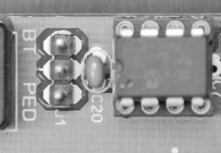
25 RECEIVER PROGRAMMING: - MASTER ERASE; (Recommended on first time installation) Action 1. All power off Response 2. Short both (PED) pedestrian and (BT) button trigger pins to centre pin (Use the key-ring supplied with the transmitters to do this as shown here) 3. Power up (RX) receiver LED flashes rapidly - stops flashing - on continuously. 4. Remove all power 5. Remove (RX) receiver pin short 6. Power up (RX) receiver LED on 25
 receiver LED flickers 2. Short Centre (RX) receiver pin to (BT) button trigger pin.")
 receiver LED remains lit in standby 4.")
 Action Response 1. Press and hold required TX button (RX) receiver led flickers 2.")
26 Learning a TX button for (BT) Full opening operation using (RX) receiver pins: - (25 user memory) Action Response 1. Press and hold required TX button (RX) receiver LED flickers 2. Short Centre (RX) receiver pin to (BT) button trigger pin. (RX) receiver LED flashes confirmation 1 flash = First transmitter learnt 2 flashes = Successful there is still memory available Multiple rapid flashes = memory full 3. Remove short after confirmation (RX) receiver LED remains lit in standby 4. Release transmitter button Learning a TX button for (PED) pedestrian ((PED) pedestrian) operation using (RX) receiver pins: - (6 user memory) Action Response 1. Press and hold required TX button (RX) receiver led flickers 2. Short Centre (RX) receiver pin to (PED) pedestrian pin (RX) receiver LED flashes confirmation 1 flash = First transmitter learnt 2 flashes = Successful there is still memory available Multiple rapid flashes = memory full 3. Remove short after confirmation (RX) receiver LED remains lit in standby 4. Release transmitter button 26
 button trigger input again. The gates can then be reversed by activating the (BT) button trigger input again.")
 Party mode is available in this mode. (See additional features below) Holiday lock out is available in this mode.")
27 OPTIONAL OPERATING MODES Dip-switch selection Mode All off STOP, START, STOP MODE When the control is activated using any (BT) button trigger input the gates will open or close and can be stopped in mid cycle using any (BT) button trigger input again. The gates can then be reversed by activating the (BT) button trigger input again. In this mode the gates will remain open where they have been stopped by button or open limit until the (BT) button trigger input is activated again. (No auto close) Party mode is available in this mode. (See additional features below) Holiday lock out is available in this mode. (See additional features below) Dip-switch selection Mode Dip-switch 1 ON SIMPLE AUTO-CLOSE (Default 15 sec.) As per Standard mode above however the following differs: - The control unit times out the pre-programmed auto-close time from any open position after which it begin closing the gates. While closing the gates any (BT) button trigger or BM input will stop and reverse the motors direction back towards the full open position. In any open position while auto-close is timing out a BM input will reset the auto-close timer. Auto-close override/party mode is available in this mode. (See additional features below) Holiday lock out is available in this mode. (See additional features below) 27
28 Dip-switch selection Mode CONDO/LOOP AUTO-CLOSE Dip-switch 2 ON (Default 15 sec.) (select when using a loop detector) In this mode all triggers are ignored while the gates are opening. On reaching the full open position the unit times out the pre-programmed auto-close time after which it will begin closing the gates. If the BM or BT button trigger input is activated while the auto-close timer is running the time will simply reset. On closing any BT button trigger input or BM input will re-open the gates to the full open position. USE THIS MODE WHEN CONECTING A LOOP DETECTOR. This mode excludes Holiday lock-out, Auto-close override/party mode Dip-switch selection Mode Dip-switch 3 ON DELAY MODE (Default 3 sec.) This mode is used when an electric lock is installed to lock the two gates together or one of the gates overlaps the other in the closed position. From the closed position Motor 1 will begin opening the programmed delay time before Motor 2 (default is 3 seconds). From the open position Motor 2 will begin closing first followed after the delay time by motor 1. This mode ensures the gates never snarl up in the closed position and can be used where one gate must open further than the other. 28
29 Dip-switch selection Mode Dip-switch 4 ON STRIKE LOCK MODE With this mode selected the courtesy light relay becomes an in line switch (N/O) to be used in the power supply circuit for a spring loaded solenoid electric lock such as an electric strike, rim or catch lock. When in the closed position the courtesy light relay will pulse momentarily, before the motors start running. The reason for this is to prevent the motors pulling against the lock before it has released. Dip-switch selection Mode Dip-switch 5 ON MAGNETIC LOCK MODE With this mode selected the courtesy light relay becomes an in line switch (N/C) to be used in the power supply circuit for a continuous supply magnetic lock. When the gates are trigger to operate in either direction, the courtesy light relay will energise for prior to the motors running and will remain energised as long as the motors are running. The reason for the delay is to prevent the motors pulling against the lock before it has released. If all that happens when triggering the gates is 20 beeps, then both dip-switch 4 and 5 have been selected to on. Correct the combination to both off, 4 on only or 5 on only as per the installation requirements to clear the error condition. 29
30 ADDITIONAL FUNCTIONS HOLIDAY LOCK-OUT Available in all but Condo/loop Auto-close mode. Action 1. Close gates Response 2. Press and hold the (PED) pedestrian button on a master remote Until 5sec beep begins. 3. Release (PED) pedestrian button on master remote Beeping will continue until confirmation or 5sec expires. 4. Press and release (BT) button trigger button on the master remote before 5sec beep stop. 1 x multiple rapid beeps will confirm holiday lock-out is active. To unlock repeat After multiple confirmation beeps gate will immediately start opening when unlocked. Holiday lock-out is available only when using a master remote. (No hardwired devices will activate or de-activate it) A master remote is a remote that has (BT) button trigger control as well as (PED) pedestrian opening control. If no (BT) button trigger confirmation trigger is received by the time the intermittent beeps stop (5sec.), the gates will not change status. COURTESY LIGHT OUTPUT Not available in strike lock or Magnetic lock mode. The courtesy light output will activate on any opening trigger ((BT) button trigger or (PED) pedestrian). The light on timer will only start timing out once the gates are closed again. 30
 button trigger button After 5sec unit will emit Multiple rapid beeps to confirm. 3. Release button after beeps 4.")
31 AUTO-CLOSE OVERRIDE/PARTY MODE Available in all but Complex Auto-close mode. Action 1. With the gates stopped at any position other than fully closed. Response 2. Press and hold any TX (BT) button trigger button After 5sec unit will emit Multiple rapid beeps to confirm. 3. Release button after beeps 4. To deactivate repeat 2 and 3 above Gates will not begin closing after auto-close time has expired. 1 x long beep and gates starts closing. If any (PED) pedestrian or (BT) button trigger input is momentarily activated while the unit is in either Holiday lock-out or Auto-close override/party mode the unit will only emit the multiple rapid beeps and not run the gate. PEDESTRIAN FUNCTION. Available in all modes Action Response 1. With the gates closed 2. Press and release any PED (pedestrian) input. 1. Three beep tones 2. Only gate 1 opens to open limit. 3. After pedestrian auto-close time the gate returns to the close position. Any further (PED) pedestrian input triggers while the gate is running are ignored except in the open position, where the auto-close timer will simply reset. Any BM input while the (PED) pedestrian routine is running will cause the gate to continue to the open position if busy opening or reverse back to the open position if closing. If already in the open position, the pedestrian auto-close timer will simply reset. If any (BT) button trigger input is activated while at any stage of the pedestrian routine, the controller will exit pedestrian mode and run both gates to the open position as per the operating mode selected. 31
32 BUZZER INDICATIONS OVERVIEW Beeps Gate status Dipswitch 6 PROG Action Response Motor Condition Solution Table ref: 2 x Rapid beeps 2 x 2sec. Beeps 3 x 1sec. Beeps 5 x Rapid beeps Gates anywhere Gates stopped Gates closed Gates anywhere but closed Off or On Off Off Off Momentary BT or Ped input Momentary BT Momentary Ped Momentary BT or Ped input Attempts to run Gates run after beeps Gates open partially None Battery flat or faulty Household mains failure Pedestrian function activated Auto-close override/party mode active Allow recharge and check for Aux devices overload. If problem persists after ±8 hours charging, replace battery Restore power supply Toggle off 34 5 x Rapid beeps Full closed Off Momentary BT or Ped input None Holiday lockout active Close gates Toggle off Beeps Gates anywhere Off Momentary BT or Ped input None Both dipswitches 4 and 5 on. Select correct setting 32 Continuous rapid beeps Gates anywhere On None None Holiday lockout active Close gates Toggle off 33 Continuous as long as trigger is held Gates anywhere Off Continuous BT or PED Input None Multiple collision lockout Clear obstruction and wait three minutes before using gates again. 27 STATUS LED OVERVIEW Off Slow flash On Rapid Flash Gates are closed Gates are running or waiting for auto-close time to time out Gates are open Gates are obstructed or have exceeded max run time. 32
33 WARRANTY: All goods manufactured by G&C Electronics cc T/A ET Systems carry a 12 month factory warranty from date of invoice. All goods are warranted to be free of faulty components and manufacturing defects. Faulty goods will be repaired or replaced at the sole discretion of ET Systems free of charge. This warranty is subject to the goods being returned to the premises of ET Systems. The carriage of goods is for the customer s account. This warranty is only valid if the correct installation and application of goods, as laid out in the applicable documentation accompanying said goods, is adhered to. All warranty claims must be accompanied by the original invoice. All claims made by the end user must be directed to their respective service provider/installer. The following conditions will disqualify this product from the warranty as laid out above. These conditions are non-negotiable. Any unauthorized non-manufacturer modifications to the product or components thereof. The use of the ET 90 BLUE PLUS swing gate operators in heavy traffic applications such as office parks and residential complexes. The following items are not included in the warranty. The battery The motor brushes Damage resultant of wind and other climatic influences such as lightning strikes. Damage due to high voltage surges on the household mains or short circuiting of the gates to the electric fencing. Damage due to infestation i.e. Ants nesting 33
UMPETHA U / Domestic sliding gate operator by ET SYSTEMS. USER GUIDE
 Domestic sliding gate operator by ET SYSTEMS. USER GUIDE 1 Table of contents Page Description 3 Safety obligations and general warnings M anual ov erride 3 How to mov e the gate by hand. Manual override
Domestic sliding gate operator by ET SYSTEMS. Installer instructions
 Domestic sliding gate operator by ET SYSTEMS. Installer instructions 1 Table of contents Page Category Introduction 3 Safety obligations and general warnings 4 Identification of components 5 Technical
ET BLUE-ROLL Domestic type roll-up garage door operator. Installation manual Revision Oct
 ET BLUE-ROLL Domestic type roll-up garage door operator Installation manual Revision Oct.08.002 support@et.co.za Technical specifications may change without prior notice. All goods are subject to the standard
TEL: G&C Electronics CC E. T.
 TEL: +27 21 448 6774 G&C Electronics CC FAX: +27 21 447 7794 E. T. CK 89/31531/23 E-mail : etsystems@icon.co.za Internet: www.et.co.za 15 Nelson Road P.O. Box 34524 Observatory Groote Schuur Cape Town
DTS 412/512/624 SLIDING GATE MOTOR INSTALLATION MANUAL
 DTS 412/512/624 SLIDING GATE MOTOR INSTALLATION MANUAL DTS SECURITY P.O.BOX 3399 EDENVALE 1610 TELEPHONE 086 1000 387 Base plate-mounting instructions Alberton 011 907 8846 Centurion 012 653 4434 Edenvale
DTS SECURITY P.O.BOX 3399 EDENVALE 1610 Base plate-mounting instructions TELEPHONE
 DTS ECO 500 SLIDING GATE MOTOR INSTALLATION MANUAL DTS SECURITY P.O.BOX 3399 EDENVALE 1610 Base plate-mounting instructions TELEPHONE 086 1000 387 Spartan +2711 392 5540 (H/O) Pretoria +2712 361 5528 Alberton
12V DC MOTORISED OPENER FOR SWING GATES Section Table of Contents Page
 12V DC MOTORISED OPENER FOR SWING GATES Section Table of Contents Page 1 Introduction 2 2 Warnings 4 3 Technical Specifications 5 4 Positioning 6 5 Wiring Diagram 7 6 Standard Installation Kit 8 7 Installation
DTS SLIDING GATE MOTOR INSTALLATION MANUAL. DTS 600 Elite with SL150 PCB DTS SECURITY P.O.BOX 3399 EDENVALE 1610 TELEPHONE
 DTS SLIDING GATE MOTOR INSTALLATION MANUAL DTS 600 Elite with SL150 PCB DTS SECURITY P.O.BOX 3399 Base plate-mounting EDENVALE instructions 1610 TELEPHONE 086 1000 387 Spartan +2711 392 5540 (H/O) Pretoria
 Access Blue Boom support@et.co.za 0860 109 238 G&C Electronics cc. T/A ET Systems 15 Nelson Rd, Observatory, Cape Town, South Africa www.et.co.za Technical specifications may change without prior notice.
Automatic Garage Door Operator
 Automatic Garage Door Operator support@et.co.za ET Systems (PTY) Ltd 15 Nelson Rd, Observatory, Cape Town, South Africa www.et.co.za Technical specifications may change without prior notice. All goods
R3R5 quick setup guide ROTARY SWING GATE OPERATOR
 R3R5 quick setup guide TM TM ROTARY SWING GATE OPERATOR 1 REQUIRED TOOLS & EQUIPMENT Check that you have all the tools required. (IM page 1) 3 SITE CONSIDERATIONS Check for the safety and suitability of
PAGE. 20. Connecting an intercom.
 PAGE C0NTENTS 2. Introduction. 2. Warnings. 2. Specifications. 3. General information. 3. Terms and definitions. 4. Installation. 5. Pedestal mount. 6. Pedestal mount inward swing. 7. Pedestal mount outward
Roll Up Door Operator
 INSTRUCTIONS & OWNERS MANUAL Roll Up Door Operator 2 INDEX Preparation before installation 4. Terms and definitions 5. Pictures & names of parts 6. Mounting the weight bar 7. Installing the operator 7.
Gate & Door Controller with LCD and Intelligent Technology
 2nd Edition Gate & Door Controller with LCD and Intelligent Technology 24Sv1 and 12Sv1 Motor Controllers Setup and Technical information for single motor controller for gates & doors Includes latest Intelligent
ET-500 AUTOMATIC SLIDE GATE MOTOR INSTALLER S MANUAL FOR ACDC500 & DC500 MODELS
 ET-500 AUTOMATIC SLIDE GATE MOTOR INSTALLER S MANUAL FOR ACDC500 & DC500 MODELS take control of your world REVISED DATE: May 2004 INDEX 1. WHAT S IN THE BOX A list of contents you will receive with this
Index. COMPACT domestic gate operator
 COMPACT domestic gate operator Index Introduction. 3. General motor layout 4. General site layout 5. Terms and definitions. 6.. Site evaluation. 6. Gate evaluation 7. Removing the lid 8. Placing the gate
APOLLO Gate Operators, Inc.
 APOLLO Gate Operators, Inc. Model 7200ETL Post Mounted Residential & Heavy Duty Commercial Slide Gate Operator INSTALLATION MANUAL 04/11 CONTENTS IMPORTANT SAFETY INSTRUCTIONS... 3 Applications... 4 Pre-Installation
CONTROL UNIT BIOS2. Manual for installation. Programmable Control board for wings gates.
 Programmable Control board for wings gates www.remotecontrolgates.co.uk Manual for installation Compatible from firmware version BIOS2BT02 CONTROL UNIT BIOS2 1. Introduzione The control unit BIOS2 is particularly
Instruction Manual MB4 Rolling garage door opener
 Instruction Manual MB4 Rolling garage door opener INSTALLATION INSTRUCTIONS OWNERS COPY 1 WARNING: It is vital for the safety of persons to follow all instructions. Failure to comply with the installation
APOLLO Gate Operators, Inc.
 APOLLO Gate Operators, Inc. Model 3500ETL/3600ETL Commercial Swing Gate Operator INSTALLATION MANUAL 01/08 CONTENTS IMPORTANT SAFETY INSTRUCTIONS. 3 Applications... 4 Pre-Installation Checklist... 5 Parts
INSTALLATION M ANUAL
 INSTALLATION MANUAL Table of Contents UL Listings Installing the Warning Sign / Precautions Methods of Installation / Compact Installation Mounting the Secondary Entrapment / Welding Gate Arn Mounting
Model 1550 Single Swing Gate Model 1650 Dual Swing Gate
 Gate Operators, Inc. Model 1550 Single Swing Gate Model 1650 Dual Swing Gate Swing Gate Operator CONTENTS Safety Precautions... 2 Applications... 3 Pre-Installation Checklist... 4 Parts Identification...
INSTALLATION AND OWNERS MANUAL
 SLIDE GATE OPERATORS: COMPACT 300 COMPACT 500 SOLO CONDO CONDO AC/DC SWING GATE OPERATORS: DURASWING GARAGE DOOR OPERATORS: LAZER SECTIONAL LAZER ROLL UP LAZER VERTICAL ROLL UP LAZER TIP UP PROUD MANUFACTURERS
HYPPOETL HYPPO DUALETL 12 VOLT DC Swing Gate Operator
 HYPPOETL HYPPO DUALETL 12 VOLT DC Swing Gate Operator Manufactured by NICE SpA INSTALLATION MANUAL 08/10 CONTENTS IMPORTANT SAFETY INSTRUCTIONS... 3 Applications...... 4 Pre-Installation Checklist... 5
TAILOR MADE METAL FABRICATIONS LTD. VEHICLE ACCESS CONTROL BARRIER (VAC B)
") TAILOR MADE METAL FABRICATIONS LTD. VEHICLE ACCESS CONTROL BARRIER (VAC B) TECHNICAL MANUAL v1.3 JANUARY 2014 Technical Manual (Updated 6 th January 2014) No Vehicle timer Vehicle delay timer Overrun timer
TAILOR MADE METAL FABRICATIONS LTD. VEHICLE ACCESS CONTROL BARRIER (VAC B) TECHNICAL MANUAL v1.3 JANUARY 2014 Technical Manual (Updated 6 th January 2014) No Vehicle timer Vehicle delay timer Overrun timer
Gate Operators, Inc. Model 7100UL Residential & Medium Duty Commercial Slide Gate Operator INSTALLATION MANUAL
 Gate Operators, Inc. Model 7100UL Residential & Medium Duty Commercial Slide Gate Operator INSTALLATION MANUAL 10-04-00 CONTENTS Safety Precautions... 2 Applications... 3 Pre-Installation Checklist...
CB CONTROL BOARD INSTRUCTION MANUAL VERSION 1.03 DATE 30/10/2000
 CB-9 3.02 CONTROL BOARD INSTRUCTION MANUAL VERSION 1.03 DATE 30/10/2000 FIRMWARE VERSION 1.09 Thank you for choosing the CB-9 control system. We encourage you to read and understand this manual prior to
EC DECLARATION OF CONFORMITY
 EC DECLARATION OF CONFORMITY Manufacturer : Address: Declares that: FAAC S.p.A. Via Benini, 1-40069 Zola Predosa BOLOGNA - ITALY 844 T control board, conforms to the essential safety requirements of the
CONTENTS INTRODUCTION
 CONTENTS INTRODUCTION 2 Lubrication 3 Physical dimensions 4 Technical specifications 5 STANDARD INSTALLATION KIT 6 WARNINGS 7 INSTALLATION OF THE UNIT 8 Initial preparations and mounting the base plate
R3 Roller Garage Door Opener
 R3 Roller Garage Door Opener INSTALLATION INSTRUCTIONS OWNERS COPY 1 WARNING: It is vital for the safety of persons to follow all instructions. Failure to comply with the installation instructions and
L I M I T E D L I F E T I M E W A R R A N T Y
 L I M I T E D L I F E T I M E W A R R A N T Y Products manufactured and sold by OMEGA RESEARCH & DEVELOPMENT, INC. (the Company), are warranted to be free from defects in materials and workmanship under
GLM SERIES CONTROL Users Manual Rev:
 GLM SERIES CONTROL Users Manual Rev: 808062 Connecting Power Page 2 Motor Terminal Wiring Diagrams Page 3 Getting Started / Setup Page 4 1. Obstruction Detection Devices Page 4 2. Checking Power and Direction
IMPORTANT SAFETY RECOMMENDATIONS
 - 1 - - 2 - IMPORTANT SAFETY RECOMMENDATIONS FAILURE TO COMPLY WITH THE FOLLOWING SAFETY RECOMMENDATIONS MAY RESULT IN SERIOUS PERSONAL INJURY, DEATH AND/OR PROPERTY DAMAGE The installation of the Automatic
CB-9 CONTROL BOARD INSTRUCTION MANUAL
 CB-9 CONTROL BOARD INSTRUCTION MANUAL AUGUST 95 The CB-9 control board is designed to automate 1 or 2 A.T.A swing gate or sliding gate drive units. This instruction manual gives detailed instructions on
IMPORTANT SAFETY RECOMMENDATIONS
 801-001-01 C IMPORTANT SAFETY RECOMMENDATIONS FAILURE TO COMPLY WITH THE FOLLOWING SAFETY RECOMMENDATIONS MAY RESULT IN SERIOUS PERSONAL INJURY AND/OR PROPERTY DAMAGE. 1. For ADDITIONAL SAFETY we STRONGLY
USERS GUIDE LO-21U LOCKOUT RELAY
 USERS GUIDE LO-21U LOCKOUT RELAY PRODUCT DESCRIPTION The LO-21U (PN: 10LO21U) is a micro-processed lock out module designed to operate on swing door applications with BEA s Bodyguard or DK-12 overhead
HIGH SPEED SLIDING GATE OPENER
 HIGH SPEED SLIDING GATE OPENER Model: is1200 + Elsema s Eclipse Control Card with GDS Operator USER MANUAL CONTENTS Section No: Page No: 1 Safety Precautions 3 2 Wiring Requirements 4 3 Installation details
The House of Gate Automation
 OPTIONAL EXTRA'S SOFT START / SOFT START This is provided as an optional extra and must be requested to fit to a new or old system. It provides an adjustable slow start and slow stop to prevent slambing
Types of Doors that can be automated using the digi.one: Sectional overhead doors, single/double, steel or timber. Tip up doors, steel or timber.
 Types of Doors that can be automated using the digi.one: Sectional overhead doors, single/double, steel or timber. Tip up doors, steel or timber. Page 1 1. Features Microprocessor based control system
INSTALLER S MANUAL AUTOMATIC GARAGE DOOR OPENER
 take control of your world INSTALLER S MANUAL AUTOMATIC GARAGE DOOR OPENER REVISED DATE: March 2004 INDEX 1. WHAT S IN THE BOX A list of contents you will receive with this product and technical specifications
Linear Actuator Swing Gate Operator Installation Manual Model # LA405-24
 Linear Actuator Swing Gate Operator Installation Manual Model # LA405-24 2 Contents Contents Product Information and Specs. 3 Mechanical 3 Electrical, Line Connections 3 Electrical, Control Connections
Installation and Set Up Instructions
 SL 2000 DC2 SLIDING GATE MOTOR KIT Solar Powered and 12V Low Voltage Installation and Set Up Instructions Unit 27 / 49 Corporate Boulevard Bayswater Vic 3153 Phone 1800 111 930 Email info@gforceautogates.com.au
FROG KIT. Installation Instructions for a Pair of gates... TECHNICAL HELPLINE THE FROG-P KIT CONSISTS OF:
 CAME UNITED KINGDOM LTD UNIT 3 ORCHARD PARK INDUSTRIAL ESTATE, TOWN STREET, SANDIACRE, NOTTINGHAM NG10 5BP TEL: 0115 921 0430 FAX: 0115 921 0431 TECHNICAL HELPLINE 0115 921 0430 INTERNET - www.cameuk.com
APOLLO Gate Operators, Inc.
 APOLLO Gate Operators, Inc. Model BA12 12 VOLT DC BARRIER ARM OPERATOR INSTALLATION MANUAL 0707 CONTENTS IMPORTANT SAFETY INSTRUCTIONS... 3 Applications... 4 Pre-Installation Checklist... 5 Operator Installation...
12V PROGRAMMABLE POWER OUT
 Page 1 ACCESSORIES STARTER IGNITION BATTERY WIRES SIDE VIEW BLUE RED YELLOW 30 A 10 A BLUE / WHITE YELLOW WHITE / BLUE WHITE / DOOR TRIGGER See opt. 16 DOOR TRIGGER (input positive) See opt. 16 PARKING
Automatic Swing door Operator SD3108 Product manual. Notes: please keep the manual properly for reference. Do carefully read this manual before use.
 Automatic Swing door Operator SD3108 Product manual Notes: please keep the manual properly for reference. Do carefully read this manual before use. Safety Warning! Please read carefully the instructions
DTS 600/800 SECTIONAL DOOR OPERATOR INSTALLATION MANUAL. Comply to: SANS IEC NRCS Cert. no /002
 DTS 600/800 SECTIONAL DOOR OPERATOR INSTALLATION MANUAL Comply to: SANS IEC 60-335-2-103 NRCS Cert. no. 88934/002 DTS SECURITY P.O.BOX 3399 EDENVALE 1610 TELEPHONE 086 1000 387 Base plate-mounting instructions
A U T O M A T I C T R A N S M I S S I O N M U L T I - C H A N N E L T W O - W A Y L C D R E M O T E S T A R T E R AS-2510 TW.
 A U T O M A T I C T R A N S M I S S I O N M U L T I - C H A N N E L T W O - W A Y L C D R E M O T E S T A R T E R S Y S T E M AS-2510 TW User Guide Transmitter Part Number and Module Serial Number...2
Sectional And Tilting Door Opener
 Sectional And Tilting Door Opener Installation Instructions and User Guide FS 600 FS 1000 FS 1200 600N 1000N 1200N FS 600-Speed FS 1000-Speed 600N 1000N S/N WARNING Please read the manual carefully before
Operators, Inc. Model 1550ETL Single Swing Gate Operator Model 1650ETL Dual Swing Gate Operator INSTALLATION MANUAL 04/07
 APOLLO Gate Operators, Inc. Model 1550ETL Single Swing Gate Operator Model 1650ETL Dual Swing Gate Operator INSTALLATION MANUAL 04/07 CONTENTS IMPORTANT SAFETY INSTRUCTIONS... 3 Applications... 4 Pre-Installation
DKC400Y AC Sliding Gate Installation Manual. Sliding Gate Opener. Model: DKC400Y. Installation Manual WARNING
 Sliding Gate Opener Model: DKC400Y Installation Manual WARNING Read and thoroughly understand all instructions before installing or operating this automatic gate opener. Failure to do so may cause serious
F ERNI K I T THE FERNI-S KIT CONSISTS OF:
 CAME UNITED KINGDOM LTD ORCHARD PARK INDUSTRIAL ESTATE TOWN STREET, SANDIACRE, NOTTINGHAM, NG10 5BP TEL: 0115 921 0430 FAX: 0115 921 0431 INTERNET - www.cameuk.com E-MAIL - enquiries@cameuk.com TECHNICAL
SWING GATE OPENERS 24V DC GEAR MOTOR
 SWING GATE OPENERS 24V DC GEAR MOTOR FOR RESIDENTIAL USER MANUAL Flashing Light Push Button Control box Gate 2 Gate 1 Index 1. Warnings 2 4. Technical Characteristics 16 2. Product Description 2.1 Applications
TWO-WAY LED AUTOMATIC TRANSMISSION REMOTE STARTER. User Guide WARNING
 TWO-WAY LED AUTOMATIC TRANSMISSION REMOTE STARTER User Guide WARNING It is the responsibility of the vehicle operator to ensure their vehicle is parked in a safe and responsible manner. 1. When leaving
CHUBBSAFES EVOLVE INSTRUCTION MANUAL
 CHUBBSAFES EVOLVE INSTRUCTION MANUAL 1 Ref: BASS-0010-B/21.02.2014 Table of content 1- CHARACTERISTICS... 4 1-1 Models... 4 1-2 Dimensions & Weights... 4 1-3 Interior fittings (standard and optional)...
INSTALLATION INSTRUCTIONS AND OPERATION MANUAL
 INSTALLATION INSTRUCTIONS AND OPERATION MANUAL UL325-2010 Compliant Commercial and Industrial Door Operator Logic Control Continuous Duty IMPORTANT INSTALLATION INSTRUCTIONS WARNING To reduce the risk
Automatic concealed bollards 275 H600 and 275 H800 Control station
 Automatic concealed bollards 275 H600 and 275 H800 Control station Technical installation manual CE Declaration Warnings for the installer Bollard electrical connection Technical specifications for control
Covers All 430, 440, 441 and CJ Series Advanced Security Systems.
 INSTALL GUIDE Covers All 430, 440, 441 and CJ Series Advanced Security Systems www.ultrastarters.com Technical Support: 866-698-5872 ext 0 support@ultrastarters.com FCC/ID Notice This device complies with
TWO-WAY LCD AUTOMATIC TRANSMISSION REMOTE STARTER. User Guide
 TWO-WAY LCD AUTOMATIC TRANSMISSION REMOTE STARTER User Guide A note concerning the battery inside the transmitter: Depending on your usage of the transmitter, the battery can last anywhere between 3 to
SKC400U SLIDING GATE OPENER OWNER S MANUAL
 SKC400U SLIDING GATE OPENER OWNER S MANUAL IMPORTANT SAFTEY INFORMATION Installing the SKC400U Gate Opener requires wiring of standard 110V electrical lines. This should only be performed by a trained
Installation and Set Up Instructions
 SL SLIDING GATE MOTOR KIT Solar Powered and 12V Low Voltage Installation and Set Up Instructions Unit 27 / 49 Corporate Boulevard Bayswater Vic 3153 Phone 1800 111 930 Email info@gforceautogates.com.au
Installation and Maintenancee Manual
 Installation and Maintenancee Manual Commercial Boom Gate Operator Model: GDS BOOM 4 and 6 A.B.N. 62 059 806 405 Nov 2013 Section No: CONTENTS Page Number: 1 Safety Precautions 3 2 Specifications 4 3 Mechanical
Installing the gate post bracket with the cardboard arm template
 ......... Installing the gate post bracket with the cardboard arm template... Installing gate posts brackets and arms for Push-to-Open or Pull-to-Open gates... Connection of Power Source 240Vac or Solar...
TWO-WAY LED MANUAL TRANSMISSION REMOTE STARTER. User Guide WARNING
 TWO-WAY LED MANUAL TRANSMISSION REMOTE STARTER User Guide WARNING It is the responsibility of the vehicle operator to ensure their vehicle is parked in a safe and responsible manner. 1. When leaving the
Model PRO-9675FT4 Owner's Manual
 Model PRO-9675FT4 Owner's Manual 4 Button Remote Start Security System With Plug-In Shock Sensor & Starter Disable FEATURES : w 2 Four Button Programmable RF Transmitters w Four Channel Code Learning Receiver
Rolling Door Opener INSTALLATION INSTRUCTION AND OWNERS MANUAL
 Rolling Door Opener INSTALLATION INSTRUCTION AND OWNERS MANUAL IMPORTANT SAFETY INFORMATION FAILURE TO COMPLY WITH THE FOLLOWING SAFETY RECOMMENDATIONS MAY RESULT IN SERIOUS PERSONAL INJURY, DEATH AND
SWING GATE OPENERS 24V DC GEAR MOTOR
 SWING GATE OPENERS 24V DC GEAR MOTOR FOR RESIDENTIAL USER MANUAL Flashing Light Push Button Control box Gate 2 Gate 1 Index Warnings 2 5. Technical Characteristics 21 1. Product Description and Applications
Congratulations. You ve just purchased the most advanced flasher available on the market today. This
 Congratulations. You ve just purchased the most advanced flasher available on the market today. This relay-isolated, solid-state module is designed to be installed into vehicles with a positive switched
Acdc slimglide roller door operator
 Acdc slimglide roller door operator Owners manual ACDC SlideGlide ROLLER DOOR OPERATOR WARNING It is vital for the safety of persons to follow all instructions. Failure to comply with the installation
OPERATING INSTRUCTIONS
 RS2-G3 ONE BUTTON 2-WAY REMOTE START SYSTEM OPERATING INSTRUCTIONS CONGRATULATIONS on your choice of a Cool Start Remote Engine Starter and Keyless Entry with DP Technology by Crimestopper Security Products
Installation and Set Up Instructions
 Model FG 5-7 / SW 5-7 / DSW 5-7 Swing Gate Motor Kit Solar powered and 12V Low Voltage Installation and Set Up Instructions Unit 27 / 49 Corporate Boulevard Bayswater Vic 3153 Phone 1800 111 930 Email
IRREVERSIBLE OPERATOR FOR SWING GATES AND DOORS
 VH IRREVERSIBLE OPERATOR FOR SWING GATES AND DOORS WARNING!! Before installing, thoroughly read this manual that is an integral part of the pack Our products if installed by qualified personnel capable
Roller Door Operator
 INSTALLATION INSTRUCTIONS AND OWNERS MANUAL Roller Door Operator IMPORTANT PLEASE READ THESE INSTRUCTIONS CAREFULLY PRIOR TO COMMENCING THE INSTALLATION OF THE OPERATOR UNIT CAUTION This Automatic Opener
Sliding Gate Opener User s Manual
 Gat Model: Sliding Gate Opener User s Manual GA2500 Gate1Access, LLC. www.gate1access.com Email: support@gate1access.com 1 Thank you for purchasing GA2500 gear rack drive sliding gate opener. We are sure
User manual. e-gate SLD-24V
 User manual FOR e-gate SLD-24V 24V Sliding Gate Operators Contents how to use your automatic gate operator...... 1 how the controls work.................. 2 how to manually release the gate...........
GARAGE DOOR OPENER OWNER S MANUAL S3/S4
 GARAGE DOOR OPENER OWNER S MANUAL S3/S4 Features! Locking door during power failure: If power failure occurs while the door is operating, the door can be released by pulling the clutch down, allowing
DOMESTIC SLIDING GATE OPERATOR
 D Turbo Pocket mechanical installation guide TM DOMESTIC SLIDING GATE OPERATOR This guide is designed specifically for installers who are familiar with the installation of standard sliding gate motors,
TWO-WAY LED MANUAL / AUTOMATIC TRANSMISSION REMOTE STARTER. User Guide WARNING
 TWO-WAY LED MANUAL / AUTOMATIC TRANSMISSION REMOTE STARTER User Guide WARNING It is the responsibility of the vehicle operator to ensure their vehicle is parked in a safe and responsible manner. 1. a)
General Information...3. Features...5. Parts Identification...6. Installation...8. Alternate Installation Electrical Fine Tuning...
 pg 1 Contents Pg. General Information...3 Features...5 Parts Identification...6 Installation...8 Alternate Installation...12 Electrical...13 Fine Tuning...17 Master and Slave...18 Wiring Diagrams...19
AUTOMATIC AND MANUAL TRANSMISSION MODELS* *MUST USE M SERIES REMOTE STARTER!
 REV.2011.7.22 80 SERIES Advanced Remote Starters & Vehicle Security Systems AUTOMATIC AND MANUAL TRANSMISSION MODELS* *MUST USE M SERIES REMOTE STARTER! WARING: NEVER USE AN AUTOMATIC TRANSMISSION STARTER
IMI vibration switch USER MANUAL INSTALLATION - OPERATION - MAINTENANCE
 USER MANUAL IMI vibration switch INSTALLATION - OPERATION - MAINTENANCE Z0929039_A ISSUED 03/2017 READ AND UNDERSTAND THIS MANUAL PRIOR TO OPERATING OR SERVICING THIS PRODUCT. contents Overview General
SYMBOL LEGEND DANGER WARNING NOTE THIS INDICATES DANGER TO THE LIFE AND HEALTH OF THE USER IS APPROPRIATE PRECAUTIONS ARE NOT TAKEN
 SYMBOL LEGEND DANGER THIS INDICATES DANGER TO THE LIFE AND HEALTH OF THE USER IS APPROPRIATE PRECAUTIONS ARE NOT TAKEN WARNING THIS WARNS THAT MATERIALS MAY BE DAMAGED IF APPROPRIATE PRECAUTIONS ARE NOT
Heavy Duty Commercial Linear Gate Operator
 MAX SUPER ARM 2300 Heavy Duty Commercial Linear Gate Operator Moves heavy gates up to 20 High traffic high wind Self-locking, Mag Lock unnecessary Overload clutch release on 3 ton impact MAX AC control
Instruction Manual for the. E-SL 450 Series
 Instruction Manual for the E-SL 450 Series Estate Slide Summary of Functions The Estate Slide is only to be used for vehicular Slide gates in a Class I setting. Class I: A vehicular gate opener (or system)
INSTALLATION GUIDE Table of Contents
 CT-3100 Automatic transmission remote engine starter systems. What s included..2 INSTALLATION GUIDE Table of Contents Door lock toggle mode..... 4 Notice...2 Installation points to remember. 2 Features..2
Saimatic Aster Gate Operator, Automation System Manual. 110V or 220V
 Saimatic Aster Gate Operator, Automation System Manual 110V or 220V 1 WARNINGS AND PRECAUTIONS Read the instructions carefully before installing the gate automation system. Keep these instructions for
AUTOMATIC CONTROL ROLLING DOOR OPENER
 AUTOMATIC CONTROL ROLLING DOOR OPENER INSTALLATION INSTRUCTION AUTOMATIC OBSTRUCT PHOTOELECTRIC BEAM ROLLING CODE SYSTEM AUTO CLOSE DOOR ANTI-THEFT SYSTEM INSTALLATION INSTRUCTION AND RDO OWNERS MANUAL
SYMBOL LEGEND DANGER WARNING NOTE THIS INDICATES DANGER TO THE LIFE AND HEALTH OF THE USER IS APPROPRIATE PRECAUTIONS ARE NOT TAKEN
 SYMBOL LEGEND DANGER THIS INDICATES DANGER TO THE LIFE AND HEALTH OF THE USER IS APPROPRIATE PRECAUTIONS ARE NOT TAKEN WARNING THIS WARNS THAT MATERIALS MAY BE DAMAGED IF APPROPRIATE PRECAUTIONS ARE NOT
Setup and Programming Manual
 Microprocessor and Handy Terminal Setup and Programming Manual Versions U04 to U19 for Sliding Door Systems P/N 159000 Rev 7-2-07 The manufacturer, NABCO Entrances, Inc. suggests that this manual be given
Installing the gate post bracket with the cardboard arm template
 ......... Installing the gate post bracket with the cardboard arm template... Installing gate posts brackets and arms for Push-to-Open or Pull-to-Open gates... Connection of Power Source 240Vac or Solar...
INSTALLATION AND OPERATION INSTRUCTIONS
 120 Cat. No. H8863 Model: WS-S-TMR INSTALLATION AND OPERATION INSTRUCTIONS IF YOU CANNOT READ OR UNDERSTAND THESE INSTALLATION INSTRUCTIONS DO NOT ATTEMPT TO INSTALL OR OPERATE INTRODUCTION This remote
General Information...3. Features...5. Parts Identification...6. Installation...8. Alternate Installation Electrical Fine Tuning...
 pg 1 Contents Pg. General Information...3 Features...5 Parts Identification...6 Installation...8 Alternate Installation...12 Electrical...13 Fine Tuning...17 Master and Slave...18 Wiring Diagrams...19
EDR G /03
 1 Important safety instructions for operation It is vital for the safety of persons to follow all instructions. Save these instructions. WARNING Do not allow children to play with door controls. Keep remote
MODEL D-WBG Wishbone Arm Barrier Gate Operator
 INSTALLATION AND OWNER S MANUAL MODEL D-WBG Wishbone Arm Barrier Gate Operator UL 325 and UL 991 Listed WITH NITRO BOARD (SEE SUPPLEMENTAL MANUAL) Serial #: Date Installed: Your Dealer: READ THIS MANUAL
Altec LMAP. (Load Moment and Area Protection) Telescopic Boom Cranes. Calibration
 Telescopic Boom Cranes. Calibration") Altec LMAP (Load Moment and Area Protection) Telescopic Boom Cranes Calibration Contents System Components...1 Anti-Two Block...1 Area Alarm...1 Boom Angle Sensor...1 Display...1 Extension Sensor...2 Function
Altec LMAP (Load Moment and Area Protection) Telescopic Boom Cranes Calibration Contents System Components...1 Anti-Two Block...1 Area Alarm...1 Boom Angle Sensor...1 Display...1 Extension Sensor...2 Function
UNDERGROUND OPERATOR FOR SWINGING GATES. WARNING!! Before installing, thoroughly read this manual that is an integral part of the pack
 UNDERGROUND OPERATOR FOR SWINGING GATES COMPAS 2 WARNING!! Before installing, thoroughly read this manual that is an integral part of the pack Our products if installed by qualified personnel capable to
Typical Installation Schematic
 The 760 Gate Automation System The FAAC 760 automation system consists of a monoblock hydraulic unit and foundation box assembly. The system is designed for underground installation, and will not alter
ARCHITECTURAL CONTROL SYSTEMS, INCORPORATED ST. LOUIS, MISSOURI
 II 1400-6 ARCHITECTURAL CONTROL SYSTEMS, INCORPORATED ST. LOUIS, MISSOURI ACSI 1426-04-AO ELECTRIC LATCH RETRACTION CONTROLLER INSTALLATION INSTRUCTIONS I.D. 1092, REV. C INSTALLATION For C-UL Listed applications,
INSTALLATION GUIDE. FCC ID NOTICE
 REV.5 RS. ADVANCED REMOTE STARTER INSTALLATION GUIDE www.security.soundstream.com FCC ID NOTICE This device complies with Part 5 of the FCC rules. Operation is subject to the following conditions:. This
Installation and a Maintenancee Manual
 Installation and a Maintenancee Manual Commercial Sliding Gate Operator MODEL: GDS 450 LV (WITH ELSEMA ECLIPSE OPERATING SYSTEM) MADE IN AUSTRALIA FROM AUSTRALIAN & QUALITY IMPORTED COMPONENTS A B N July