INSTRUCTION MANUAL_. Specifications. Electrical.
|
|
|
- Pierce Grant Tate
- 6 years ago
- Views:
Transcription
1 308 Industrial Park Road Starkville, MS USA Ph: (662) FAX: (662) DX-77A 7-Band HF Vertical 10, 12, 15, 17, 20, 30, 40-Meter INSTRUCTION MANUAL_ General Description The "DX-77-A" is an omnidirectional, self-supporting, automatic-bandswitching vertical radiator which operates on the 10, 12, 15, 17, 20, 30 and 40 meter Amateur bands. No ground radials are used with the DX-77-A. The DX-77-A design is based upon an off-center-fed dipole, sometimes called a "Windom" antenna. Highefficiency high-power traps are used to isolate the active sections of this antenna. The DX-77-A uses a heavy-duty tiltable mast clamp which will accept masts of up to 2 118" inches O.D. The entire antenna may be easily raised and lowered for tuning purposes and for recreational - vehicle (RV) installations. The DX-77-A also features an overall length of 29 feet (8.8 m), which contributes to exceptional bandwidths on 40 and 20 meters. Specifications Electrical. Frequency Bands: 2:1 VSWR Bandwidth 40m MHz 100 KHz min.; 150' KHz typ. 30m MHz 100' KHz min., 150 KHz tpy. 20m MHz 200 KHz min., 250 KHz typ. 17m MHz 200 KHz min., 250: KHz typ. 15m MHz 400 KHz min., 500 KHz typ. 12m MHz 300 KHz min., 400 KHz typ. lom MHz 1500 KHz min., 1700 KHz typ. VSWR' of Resonance less than. 1.5:1 Maximum Power (at 95 F) watts ave., 1500 watts PEP Gain unity gain (compared to half-wave vertical dipole) Input Impedance...50 ohms Mechanical: Total Height feet (8.8' m) Bottom Radial Elements...4 each, 5 feet (1.5 m) Allowable Mast O.D inches (44-53 mm) Recommended Masts8 to 10 foot length) Aluminum, 2 inch O.D.,.125 wall min Steel, 2 inch O.D., :058 wall min. Weight lbs. (11.35 kg:) Wind Area ' sq. ft. (.1767 sq. m.) Maximum Wind Speed (unguyed) mph ( Kmph)
2 Choose Location Choose a location for the DX-77-A in the clear, away from trees, buildings, power-lines and other metallic objects. The DX-77-A should be attached to a steel mast or heavy aluminum mast which is capable of supporting a structure of this size. The DX-77-A does NOT utilize a ground radial system, and the addition of ground radials will NOT improve the performance. However, high-conductivity ground in the immediate vicinity will increase the gain by decreasing ground losses. WARNING: Installation of this product near power lines is dangerous! For your safety, follow the installation instructions. Failure to do so could result in serious or fatal injury! The mast height can be from 4 feet (1.2 m) to 10 feet (3 m). The recommended height is approximately 7 feet (2.1 m). This puts the bottom radials above eye-level and out-of-reach of most children! A 10 foot (3 m) 2" O.D. steel mast set 3 feet (1 m) into concrete makes an ideal support. The DX-77-A may also be mounted on a roof tripod or on a tower structure, however, tuning should be performed prior to installation. Since wind survival is 60 mph, tower mounting is discouraged. If you guy the support mast or tripod, use non-metallic guy ropes. A ground wire may be connected to the mounting brackets (Item 15) for lightning protection. Tools Required: Tape Measure, 12 feet for assembly, and tuning Nut Driver, 3/8 inch for tuning and for assembly' of matching unit Nut Driver, 5/16 inch for tightening of tubing clamps 2 each 'Open-End Wrench, 1/2 inch for base bracket assembly 2 each Open-End Wrench, 7/16 inch for assembly of matching unit An adjustable wrench may be' used in place of the open-end wrenches. Pre-Assembly When unpacking your antenna, check all parts against the parts list in the rear of this manual. Read the instructions and study the illustrations before beginning your assembly and installation. The DX-77-A has been partially pre-assembled for your convenience. Each trap assembly is marked with a label: this label also indicates the depth of insertion into the adjacent assembly. The trap assemblies have frequency labels that you can use as an approximate guide to tune your DX-77-A to its resonant frequencies. If these labels have worn off, or are missing, the normal insertion depth is 3 inches (76mm) The DX-77-A incorporates several improvements over the original DX-77. Rain-caps are included with the 17, 20, and 30 meter traps to prevent detuning from rain, ice, and snow accumulation.
3 Installation of Tubing Clamps Select the proper size tubing clamp as shown in the chart. When installing the clamps, place the clamp near the tube end with the top of the clamp over the slot in the tube as shown in Figure 1. After adjustment of the tubing lengths, tighten the clamp with a 5/16 inch nut driver, socket, or open end wrench until the tubing will not twist or telescope. Part Number Description Fits Tubing Sizes Clamp, Size # all stainless steel 1/2 and 3/4" 5/6" hex head screw Part Number Description Fits Tubing Sizes Clamp, Size # all stainless steel 1" 5/6" hex head screw Part Number Description Fits Tuubing Sizes Clamp, Size # all stainless steel 1 1/4" 5/6" hex head screw Figure 1 Clamp Assembly
4 NOTE Tubing insertion depth is 3" (76 mm) unless otherwise noted. Ite m No. Description No. Description 1 Tube, 7/16" x 62" 10 Tubing Section #2, 1 1/4" x 48" 3 Tube, 5/8" x 48" swaged 11 Tubing Section #1 6 Trap Assembly #3, 30 meter 24 Clamp, #6 tube 7 Trap Assembly #2, meter 25 Clamp, #10 tube 8 Trap Assembly #1, meter 26 Clamp, #16 tube 9 Tubing Section #3, 1 1/8" x 48" 27 Caplug, 7/16" black ; it Item Figure 2 Overall View of DX77-A
5 Assembly of Antenna If available, place two saw-horses approximately 15 feet (4.6m) apart. These will be used to support the antenna during assembly. Select Tubing Sections #1, #2, and #3 (Items 11, 10, and 9). Insert Section #2 into the top of Section #1. Place a size #16 tubing clamp over the slot in Section #1 and tighten. Insert Section #3 into the top of Section #2. Place a size #16 tubing clamp over the slot in Section #2 and tighten. See Figure 2 for dimensions. Select Trap Assembly # 1 ( meter) and a size #16 tubing clamp. Place the tubing clamp over the top of Section #3 and insert the Trap Assembly #1 into the top of Section #3 to the label. Tighten the clamp. Select Trap Assembly #2 (17-20 meter) and a size #16 tubing clamp. Place the tubing clamp over the top of the #1 Trap Assembly and insert the #2 Trap Assembly to the label. Rotate the #2 Trap Assembly so that the lower capacitor does not touch any part of the #1 Trap Assembly. Select Trap Assembly #3 (30 meter) and a size #10 tubing clamp. -Place the tubing clamp over the top of the #2 Trap Assembly and insert the #3 Trap Assembly to the label. Tighten the clamp. Select the 5/8 x 48 inch swaged tube and #10 tubing clamp. Place the tubing clamp over the top of the #3 Trap Assembly and insert the tube 3 inches, so that 45 inches is exposed. Tighten the clamp. Select the 7/16 x 55 inch tube and #6 tubing clamp. Install this tube in the same manner so that 54 inches is exposed. Tighten the clamp. Refer to Figures 1 and 2 for assistance. Select the four (4) radial brackets, x 1 inch screws, #10 internal lockwashers, nuts, and four (4) 5/8" x 7 1/2" tubes. Loosely preassemble the brackets and only 3 tubes on a flat surface first. Place this assembly on the fiberglass portion of Base Section #l, and finish assembling as shown in Figure 3. The bottom of this bracket assembly should be 1/2" above the 2" OD tubing part of Section #1. NOTE: To fold this assembly for transport, remove the outer screw from each joint. Swivel the radial tubes up alongside the radiator tubing. Install the screws back into the joint holes and tighten for safekeeping. Select the four (4) 7/16" x 52" tubes and four (4) #6 tubing clamps. Place each tubing clamp over the end of each of the 5/8" x 7 1/2" radial tubes. Insert each of the 7/16" tubes into the 5/8" radial tubes so that 46" (1.17 m) is exposed. Tighten all four clamps. Place a caplug over the end of each tube.

 bottom")


6 Mathing Unit Assembly Select the DX-77-A matching unit, upper clamp, Assemble as shown in Figure 4. Tighten all con- two (2) bottom clamps, x 1" screws, nections securely. nuts and lockwashers, 1/4"- 20 x 1" bolt, 1/4"-20 nuts and lockwashers. Figure 4 Matching Unit Assembly
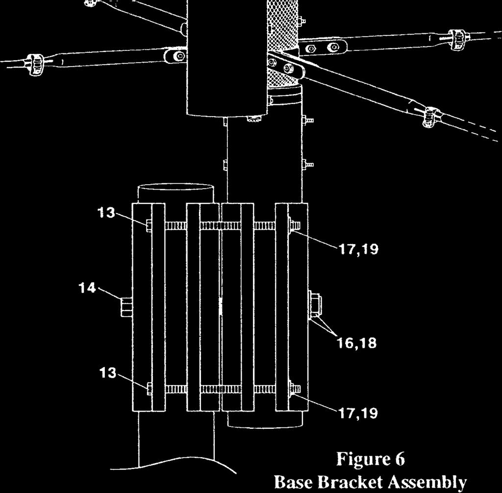
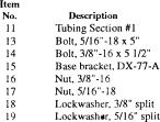
7 Base Bracket Assembly Select the DX-77-A Base Parts Pack. If you will be using the tilt-over feature, you will need to drill a 3/8" hole through your support mast at the mounting location. To do this easily, first install two of the base brackets on your support mast and secure. Use a 3/8" drill bit to drill through each side of the mast using the holes in the brackets as guides. Assemble the mast brackets to both the support mast and to Tubing Section # 1 Assembly as shown in Figure 5. (Temporarily remove Tubing Section #2 and above while assembling the mast brackets to the mast). Practice swivelling Section #1 to a vertical position and installing the other bolts. With help from at least one more person, reattach the rest of the antenna, then swivel the DX-77-A to a vertical position and install all the mounting bolts as shown in Figure 6. Tighten securely! NOTE: Tightening the pivot bolt more (Item 14) will help hold the antenna during raising and lowering. CAUTION: Do not attempt to raise or lower this antenna by yourself. Item No. Description ion Item 11 Tubing Section #1 No. Description 14 Bolt, 3/8"-16 x 5 1/2" Figure 5 16 Nut, 3/8" Base bracket, DX-7 7 Base Bracket Assembly 18 Lockwasher, 3/8" split
8 Tuning the DX-77-A Each band on the DX-77-A can be independently tuned for resonance by adjusting each trap resonance on the meter bands, and by adjusting the tip length on 40 meters. The DX-77-A radiating element length may also be adjusted slightly between the trap assemblies. Each trap consists of one coil and at least one capacitor tube. The center conductor of each capacitor tube is attached to the top of the coil, and the outside tubing of each capacitor is attached to the bottom of the coil by an adjustable-position clamp. The DX-77-A normally comes with this adjustable clamp positioned near the bottom of the coil. This sets the resonance of each band near the top (US-phone) end. To adjust the trap lower in frequency, loosen this clamp, and slide it downward, and retighten. This adds a length of the capacitor tubing and radiator tubing in series with the coil and effectively increases the inductance, thereby lowering the trap resonance. This in turn lowers the antenna resonance on that band. this adjustment can lower the resonant frequency from 100 KHz on 30 meters to as much as 400 KHz on 10 meters. The match on all bands (lower SWR) is pre-set by the matching network in the plastic box and by the length of the radial tubes. If you find that your SWR is too high because of surrounding objects or proximity to the ground, you may try adjusting the lengths of the radial tubes. If you are close to the ground (less than 48 inches), try adjusting all of the radial tubes shorter to decrease the capacitive loading effect. If you are at least 5 feet above ground and at least 20 feet from any fence, building or vertical metallic object, and your SWR is above 1.5:1 at resonance on all bands, you may have a problem in the matching network. If ALL of the bands show high SWR, check where the black wire is connected. If the black wire is connected to ground through the mounting bracket instead of to the radial tubes, all of the bands will show resonances from 200 KHz to 1000 KHz too low! Do not allow anything to touch the radial elements except the black wire! The resonances on the DX-77-A may also be adjusted by increasing or decreasing the length of the vertical radiator. The 10, 12, and 15 meter bands can be lowered in frequency by setting the length of this trap assembly to 44 inches instead of 42 inches. The lower bands will also be affected slightly. Also, the 17 and 20 meter bands can be raised in frequency approx. 100 KHz by setting the length of the meter trap assembly to 32 1/2 inches instead of 34 inches. The 30 and 40 meter bands will also be affected slightly. The 30 meter band can be raised in frequency approx. 50 KHz by setting the length of the 30 meter trap assembly to 29 inches instead of 31 1/2 inches. Again, 40 meters will be affected with this change. To change the resonance on 40 meters, adjust the length of the tip (nominally 54 inches),- longer to go lower, and shorter to go higher. This adjustment will not affect the other bands!
9 DX-77-A Mining Guide: To Lower Resonance: To Raise Resonance: 10 meters: Move 10m adj. clamp lower Shorten 42" length of trap 12 meters: Move 12m adj. clamp lower Shorten 42" length of trap 15 meters: Move 15m adj. clamp lower Shorten 42" length of trap 17 meters: Move 17m adj. clamp lower Shorten 34" length of trap 20 meters Move 20 m adj. clamp lower Shorten 34" length of trap Lengthen 34" length of trap 30 meters: Move 30m adj. clamp lower Shorten 31 1/2" length of trap Lengthen 31 1/2" length of trap 40 meters: Lengthen tip dimension Shorten tip dimension NOTE: When lengthening trap section dimensions, allow at least 2" insertion into the 1 1/8" tubes and at least 1" insertion of the 40m tip into the next section. Toning Guide inch = KHz 1 inch = KHz 1 inch = KHz 1 inch = KHz 1 inch = KHz NOTE: The tuning of one band may affect the tuning of adjacent bands. Check these frequencies before proceeding to the next band.


10 Detail A Front View Detail B Side View


11 Service Information If you are encounter technical problems and need assistance, you should contact Hy-Cain Customer Service Department. All requests, inquires, warranty claims, or for ordering replacement parts, contact: Hy-Gain 308 Industrial Park Road Starkville, Mississippi USA Phone: FAX: Typical VSWR Curves: NOTE: VSWR will vary with height above ground and location near houses, fences, masts, and other surrounding objects.
12 DX-77-A Parts List Item Part Tube, 7/16" x 62" Tube, 7/16" x 52" Tube, 5/8" x 48" swaged Tube, 5/8" x 7 1/2" swaged Matching Unit, DX-77-A Trap Assembly #3, 30m Trap Assembly #2, 17-20m Trap Assembly #1, m Tubing Assembly #3, 1 1/8"x 48" Tubing Assembly #2, 1 1/4"x 48" Tubing Assembly #1 (Base) Parts Pack, DX-77-A Base Bolt, 5/16"- 18 x 5" Bolt, 3/8"-16 x 5 1/2" Base bracket, DX-77-A Nut, 3/8" Nut, 5/16" Lockwasher, 3/8" split Lockwasher, 5/16" split Parts Pack, DX-77-A Clamps, etc Clamp, matching unit - top Clamp, matching unit - bottom Clamp, radial element Clamp, #6 tube Clamp, #10 tube Clamp, #16 tube...: Caplug, 7/16" black Bolt, 1/4"-20 x l" Bolt x 1" Nut, Hex Nut, 1/4"-20 Hex Lockwasher, 1/4" internal Lockwasher, #10 internal... 15
13 Item Number Part Number DX-77-A Parts List (continued) Description Qty Coil Assembly, 30m Coil Assembly, 20m Coil Assembly, 17m Coil Assembly, m Capacitor Assembly, 30m Capacitor Assembly, 20m Capacitor Assembly, 17m Capacitor Assembly, 15m Capacitor Assembly, 12m Capacitor Assembly, 10m... l NOTE: Some extra small parts are included as spares.
14 LIMITED WARRANTY Hy-Gain Warrants to the original owner of this product, if manufactured by Hy-Gain and purchased from an authorized dealer or directly from Hy-Gain to be free from defects in material and workmanship for a period of 12 months for rotator products and 24 months for antenna products from date of purchase provided the following terms of this warranty are satisfied. 1. The purchaser must retain the dated proof-of-purchase (bill of sale, canceled check, credit card or money order receipt, etc.) describing the product to establish the validity of the warranty claim and submit the original or machine reproduction of such proof of-purchase to Hy-Gain at the time of warranty service. Hy-Gain shall have the discretion to deny warranty without dated proof-of-purchase. Any evidence of alteration, erasure, or forgery shall be cause to void any and all warranty terms immediately. 2. Hy-Gain agrees to repair or replace at Hy-Gain s option without charge to the original owner any defective product under warranty, provided the product is returned postage prepaid to Hy-Gain with a personal check, cashiers check, or money order for $8.00 covering postage and handling. 3. Under no circumstances is Hy-Gain liable for consequential damages to person or property by the use of any Hy-Gain products. 4. Out-of-warranty Service: Hy-Gain will repair any out-of-warranty product provided the unit is shipped prepaid. All repaired units will be shipped COD to the owner. Repair charges will be added to the COD fee unless other arrangements are made. 5. This warranty is given in lieu of any other warranty expressed or implied. 6. Hy-Gain reserves the right to make changes or improvements in design or manufacture without incurring any obligation to install such changes upon any of the products previously manufactured. 7. All Hy-Gain products to be serviced in-warranty or out-of-warranty should be addressed to hy-gain, 308 Industrial Park Road, Mississippi 39759, USA and must be accompanied by a letter describing the problem in detail along with a copy of your dated proof-of-purchase. 8. This warranty gives you specific rights, and you may also have other rights which vary from state to state.
2009 MFJ ENTERPRISES, INC.
 Model MFJ-4416BRC INSTRUCTION MANUAL CAUTION: Read All Instructions Before Operating Equipment MFJ ENTERPRISES, INC. 300 Industrial Park Road Starkville, MS 39759 USA Tel: 662-323-5869 Fax: 662-323-6551
Transceiver Voltage Conditioner
 Transceiver Voltage Conditioner Model MFJ-4403 INSTRUCTION MANUAL CAUTION: Read All Instructions Before Operating Equipment MFJ ENTERPRISES, INC. 300 Industrial Park Road Starkville, MS 39759 USA Tel:
ASSEMBLY AND INSTALLATION INSTRUCTIONS 738XB 70 CM OSCAR BOOMER MHz COMMUNICATIONS ANTENNAS (7/94)
") ASSEMBLY AND INSTALLATION INSTRUCTIONS 7XB 70 CM OSCAR BOOMER 432-4 MHz COMMUNICATIONS ANTENNAS 951451 (7/94) WARNING THIS ANTENNA IS AN ELECTRICAL CONDUCTOR. CONTACT WITH POWER LINES CAN RESULT IN DEATH,
ASSEMBLY AND INSTALLATION INSTRUCTIONS 7XB 70 CM OSCAR BOOMER 432-4 MHz COMMUNICATIONS ANTENNAS 951451 (7/94) WARNING THIS ANTENNA IS AN ELECTRICAL CONDUCTOR. CONTACT WITH POWER LINES CAN RESULT IN DEATH,
MODEL DB-1015A 10- and 15-Meter Duo-Band Antenna Order No
 MODEL DB-1015A 10- and 15-Meter Duo-Band Antenna Order No HY-GAIN ELECTRONICS CORPORATION 8601 Northeast Highway 6 Lincoln, Nebraska 68505 Telephone 464-9151 Area Code 402 printed. copyri ght Hy-Gain Electronics
LIST OF ILLUSTRATIONS
 TABLE OF CONTENTS (Cont.) CHAPTER 4......4-1 Installation......4-1 Installation on a Crank-Up Tower........4-1 Attaching the Antenna to the Mast......4-1 Other Types of Towers......4-3 Lightning Protection......4-3
12 Meter Add-On Kit for the Hustler 4/5/6-BTV Vertical Antennas
 12 Meter Add-On Kit for the Hustler 4/5/6-BTV Vertical Antennas DXE-AOK-12M Patent Pending DXE-AOK-12M-INS Revision 1d DXE-AOK-12M Installed on a BTV with optional Tilt Base and Direct Coax Feedpoint DX
CW Optimizer Capacity Hat Kit. 75/80 and 80/40 Thunderbolt Vertical Antennas. for the DXE-7580-THK
 CW Optimizer Capacity Hat Kit for the 75/80 and 80/40 Thunderbolt Vertical Antennas DXE-7580-THK DXE-7580-THK-INS Revision 1a DX Engineering 2012 P.O. Box 1491 Akron, OH 44309-1491 USA Phone: (800) 777-0703
Single Leg AM/CM 20, 24 and 30
 800/846-9659 www.equalizersystems.com Installation and Operation Guide April 2007 Single Leg AM/CM 20, 24 and 30 Installation Tools Required for Installation Ratchet, sockets and wrench set Wire cutters/crimpers
PRORAC CONTRACTOR SERIES UNIVERSIAL STEEL ECONO TRUCK RACK INSTALLATION INSTRUCTIONS
 PRORAC CONTRACTOR SERIES UNIVERSIAL STEEL ECONO TRUCK RACK INSTALLATION INSTRUCTIONS 500 Lb. Capacity Package Contents: Parts Hardware (4) Legs (12) 3/8-16 x 1-1/4 Hex Head Bolts (36) Flat Washers (4)
ASSEMBLY INSTRUCTIONS FOR TRANSIT CONNECT RACK
 ASSEMBLY INSTRUCTIONS FOR TRANSIT CONNECT RACK FTC948-1 shown above Package Contents: HARDWARE KIT PARTS (4) 3/8-16 x 3 CARRIAGE BOLTS (1) RAIL DRIVER S SIDE ASSEMBLY (16) 3/8-16 x 2 CARRIAGE BOLTS (1)
UNIVERSAL REMOVABLE REAR CROSSBAR CONVERSION INSTRUCTIONS FOR HAULER RACK II & SERVICE BODY SERIES RACKS
 UNIVERSAL REMOVABLE REAR CROSSBAR CONVERSION INSTRUCTIONS FOR HAULER RACK II & SERVICE BODY SERIES RACKS T11U2863-1 shown above Package Contents: (2) Y BRACKETS (8) 3/8-16 x 2 CARRAIGE BOLTS (4) 3/8-16
Please visit for the latest version of these installation instructions.
 Please visit www.blueox.com for the latest version of these installation instructions. BX1986 Please read BOTH these and the General Information sheet prior to installing or operating this equipment. 1.
advanced FLOW engineering Instruction Manual P/N:
 advanced FLOW engineering Instruction Manual P/N: 46-79001 Make: Jeep Model: Wrangler JK Year: 2007-2015 Please read the entire instruction manual before proceeding. Ensure all components listed are present.
Installation Instructions READ THOROUGHLY BEFORE BEGINNING Signature Series Rail Kit Dodge Ram Trucks-all, including Mega-cabs
 INDEX Failure to follow all of these instructions may result in death or serious injury!. GUIDELINES FOR MATCHING TOW VEHICLE AND TRAILER. Pages -. DRILLED AND BOLTED INSTALLATION FIGURE. Page 4. NO-DRILL,
VAN LADDER RACK FOR ULR-E INSTRUCTIONS P/N ULRDD-1
 VAN LADDER RACK FOR ULR-E INSTRUCTIONS P/N ULRDD-1 Before you begin: Remove all components from the shipping carton. The rack should be assembled on a padded surface such as carpet to prevent scratching
Single Leg AM / CM 20, 24 and 30. Installation
 1-800-846-9659 www.equalizersystems.com Installation and Operation Guide January 2011 Single Leg AM / CM 20, 24 and 30 Installation Tools Required for Installation Ratchet, Sockets and Wrench Set Wire
Installation and Operation Guide October 2010
 1-800-846-9659 www.equalizersystems.com Hydraulic Trailer Jack Installation and Operation Guide October 2010 Hydraulic Trailer Jack AJ Dual Leg General Description Dual leg trailer jack Lifting capacity:
ASSEMBLY INSTRUCTIONS FOR V10SE & V11SE E MOUNT RACKS P/N V10SEV-1 / V11SEV-1
 ASSEMBLY INSTRUCTIONS FOR V10SE & V11SE E MOUNT RACKS P/N V10SEV-1 / V11SEV-1 V10SEV-1 shown above Package Contents: HARDWARE KIT (6) CLIPS (6) CLIP END CAPS (8) 3/8-16 x 3 CARRAIGE BOLTS (16) 3/8-16 x
Please visit for the latest version of these installation instructions.
 Please visit www.blueox.com for the latest version of these installation instructions. BX2409 2009-18 Dodge Ram 1500 Sport/ST/Laramie Limited Please read BOTH these and the General Information sheet prior
Please visit for the latest version of these installation instructions.
 Please visit www.blueox.com for the latest version of these installation instructions. Attachment Tab Height: 15-1/2 Serial Number Attachment Tab Width: 24 Please read BOTH these and the General Information
Please visit for the latest version of these installation instructions.
 Please visit www.blueox.com for the latest version of these installation instructions. Attachment Tab Height: 19-1/2 Serial Number Attachment Tab Width: 19 Please read BOTH these and the General Information
Important Information
 Boat Lift Boss Installation Instructions For Metal Craft Lifts (Kit 3005.7204) Important Information Before installation, read and understand all instructions and warnings. All 120 Volt units MUST have
Operating and Installation Instructions
 Model Number 20902 Fabricator's Power Module Kit - Aluminum Operating and Installation Instructions CAUTION! This product is to be installed only by persons knowledgeable in the repair and modification
Please visit for the latest version of these installation instructions.
 Please visit www.blueox.com for the latest version of these installation instructions. Attachment Tab Height: 16 Serial Number Attachment Tab Width: 35 Please read BOTH these and the General Information
Installation manual. Replacement front sway bar end link Dodge Ram Dodge Ram 1500 Part # 30927
 Part # 30927 1998-2012 Dodge Ram 2500-3500 1998-2001 Dodge Ram 1500 Replacement front sway bar end link Part # Description Qty. 30927NB1 Hardware bag 1 30927NB2 Hardware bag 1 30927INST Instruction manual
Please visit for the latest version of these installation instructions.
 Please visit www.blueox.com for the latest version of these installation instructions. Attachment Tab Height: 21 Serial Number Attachment Tab Width: 31.25 Please read BOTH these and the General Information
Please visit for the latest version of these installation instructions.
 Please visit www.blueox.com for the latest version of these installation instructions. BX3796 Attachment Tab Height: 13-1/2 Serial Number Attachment Tab Width: 24 Please read BOTH these and the General
Please visit for the latest version of these installation instructions.
 Please visit www.blueox.com for the latest version of these installation instructions. BX1728 2017-18 GMC Acadia (Includes Denali & All-Terrain) (No Limited) Attachment Tab Height: 16 Serial Number Attachment
advanced FLOW engineering Stage-2 Air Intake Instruction Manual P/N: / /
 advanced FLOW engineering Stage-2 Air Intake Instruction Manual P/N: 51-76202/54-76202/75-76202 Make: Jeep Model: Wrangler (TJ) Year: 1997-2006 Engine: I6-4.0L Please read the entire instruction manual
INSTALLATION MANUAL Model
 VAN SOLUTIONS FOR THE WAY YOU WORK INSTALLATION MANUAL Model 2291-3-01 Weather Guard / Knaack 800-456-7865 Toll Free 420 E. Terra Cotta Ave 800-334-2981 Fax Crystal Lake, IL 60014 USA Knaack.OrderEntry@wernerco.com
RV Stabi-Lizer Installation & Operation Manual Effective May 2018
 RV Stabi-Lizer Installation & Operation Manual Effective May 2018 Contents Installation Pages 2 & 3 Operation Page 4 Manual override Page 5 Drawings Page 6 & 7 Warranty Page 8 Tools required for installation
Installation Instructions **THIS RAIL MOUNTING KIT USES 11 BOLTS**
 Installation Instructions CUSTOM QUICK INSTALL MOUNTING KIT FORD SUPER DUTY Part Numbers: 50074 WARNING:Under no circumstances do we recommend exceeding the towing vehicle manufacturers recommended vehicle
Please visit for the latest version of these installation instructions.
 Please visit www.blueox.com for the latest version of these installation instructions. BX1715 2014-15 Chevy Malibu (All Models) 2016 Chevy Malibu Limited (No Active Shutter or E-Assist) Attachment Tab
advanced FLOW engineering Instruction Manual P/N: Make: Can-AM Model: Maverick Year: Engine: 1000cc
 advanced FLOW engineering Instruction Manual P/N: 85-80066 Make: Can-AM Model: Maverick Year: 2013-2016 Engine: 1000cc Please read the entire instruction manual before proceeding. Ensure all components
OWNER S MANUAL. Sentry & Sentry CT THREE YEAR WARRANTY. Phone: ( ) Fax: (605) SAFETY INSTRUCTIONS
 Fax: (605) SAFETY INSTRUCTIONS") OWNER S MANUAL Sentry & Sentry CT HARD ROLL-UP TRUCK BED COVER SAFETY INSTRUCTIONS 1. Do not place objects on or against cover or framework. 2. Do not tie cargo to truck bed cover framework. 3. Never allow
OWNER S MANUAL Sentry & Sentry CT HARD ROLL-UP TRUCK BED COVER SAFETY INSTRUCTIONS 1. Do not place objects on or against cover or framework. 2. Do not tie cargo to truck bed cover framework. 3. Never allow
42 ft/lbs PARTS LIST
 ASSEMBLY OPERATION REPLACEMENT PARTS Chevy Venture 04-06 TP20044,Rev.5 BOLT TORQUE SPECIFICATIONS STANDARD BOLTS: METRIC BOLTS: Size Grade Torque 5/16" 5 20 ft/lbs. 3/8" 5 35 ft/lbs. 7/16" 5 56 ft/lbs.
INSTALLATION INSTRUCTIONS
 THANK YOU FOR CHOOSING KURYAKYN! Protect yourself and others from possible injury and property damage or loss. Pay close attention to all instructions, warnings, cautions, and notices regarding the installation,
GRADING SCRAPERS INDUSTRIAL SERIES OPERATION, SERVICE & PARTS MANUAL FOR MODELS: GSI7-SS, GSI7, GSI8, GSI10, & GSI12.
 GRADING SCRAPERS INDUSTRIAL SERIES OPERATION, SERVICE & PARTS MANUAL FOR MODELS: GSI7-SS, GSI7, GSI8, GSI10, & GSI12 September 2006 FORM: IndGradingScrpr.QXD TABLE OF CONTENTS Safety Information......................1-2
INSTALLATION MANUAL VAN SOLUTIONS FOR THE WAY YOU WORK. Model E. Terra Cotta Ave Fax
 VAN SOLUTIONS FOR THE WAY YOU WORK INSTALLATION MANUAL Model 2291-3-01 Weather Guard / Knaack 800-456-7865 Toll Free 420 E. Terra Cotta Ave 800-334-2981 Fax Crystal Lake, IL 60014 USA Knaack.OrderEntry@wernerco.com
E9X/E8X/E6X CHASIS VEHICLES (With N54 Motors)
") Installation Manual P/N 1-301-1706-01 (N54 Coil-Pack Conversion Kit) E9X/E8X/E6X CHASIS VEHICLES (With N54 Motors) Warning: This installation is not recommended for a novice or the new guy in the shop.
Installation Manual P/N 1-301-1706-01 (N54 Coil-Pack Conversion Kit) E9X/E8X/E6X CHASIS VEHICLES (With N54 Motors) Warning: This installation is not recommended for a novice or the new guy in the shop.
Swing Arm Magnifying Lamp
 Owner s Manual & Safety Instructions Save This Manual Keep this manual for the safety warnings and precautions, assembly, operating, inspection, maintenance and cleaning procedures. Write the product s
Please visit for the latest version of these installation instructions.
 Please visit www.blueox.com for the latest version of these installation instructions. BX1726 (All Models) (No Active Shutters or E-Assist) Attachment Tab Height: 12 Serial Number Attachment Tab Width:
INSTALLATION MANUAL Models &
 VAN SOLUTIONS FOR THE WAY YOU WORK INSTALLATION MANUAL Models 2295-3-01 & Weather Guard / Knaack 800-456-7865 Toll Free 420 E. Terra Cotta Ave 800-334-2981 Fax Crystal Lake, IL 60014 USA Knaack.OrderEntry@wernerco.com
Please visit for the latest version of these installation instructions.
 Please visit www.blueox.com for the latest version of these installation instructions. BX1138 2014-18 Jeep Cherokee (No Trailhawk) (Includes Adaptive Cruise) Attachment Tab Height: 19-1/2 Serial Number
SHOP PRESS ASSEMBLY INSTRUCTIONS
 SHOP PRESS ASSEMBLY INSTRUCTIONS 240AO - 40 Ton Air Over Shop Press PRESS SPECIFICATIONS Sunex Part No. A B C D E F G H 240AO 74.2" 32" 29.7" 12" 6.7" 1.2" Air Assist Y(2) A - Total Height B - Inside Width
8700 Series 8900 Series Rolling Air Jacks
 8700 Series 8900 Series Rolling Air Jacks Installation, Operation & Repair Parts Information - NOTICE - AIR SUPPLY MUST HAVE IN-LINE FILTER/REGULATOR/LUBRICATOR (NOT INCLUDED) TO VALIDATE THE ROLLING AIR
Installation manual. Rear traction bars. Ram Ram Part # Part # Important customer information:
 Installation manual Rear traction bars Ram 2500 2003-2013 Ram 3500 2003-2012 Part # 30991 sj12062011rev.01 Part # 30991 2003-2013 Ram 2500, 2003-2012 Ram 3500 Rear traction bars Part # Description Qty.
Please visit for the latest version of these installation instructions.
 Please visit www.blueox.com for the latest version of these installation instructions. BX3623 2017-19 Subaru Impreza (Manual) (No Fog Lights) Attachment Tab Height: 13 Serial Number Attachment Tab Width:
Please read BOTH these Installation Instructions and the General Information sheet prior to installing or operating this equipment.
 Attachment Tab Height: 24-1/4 Serial Number Attachment Tab Width: 24 Please read BOTH these and the General Information sheet prior to installing or operating this equipment. 1. Blue Ox towing products
GERINGHOFF. Corn Header Manual f HEADSIGHT.COM
 GERINGHOFF Corn Header Manual 09020701f HEADSIGHT.COM 574.546.5022 About Headsight Headsight Contact Info Headsight, Inc. 4845 3B Road Bremen, IN 46506 Phone: 574-546-5022 Fax: 574-546-5760 Email: info@headsight.com
Please visit for the latest version of these installation instructions.
 Please visit www.blueox.com for the latest version of these installation instructions. BX1139 2018 Jeep Wrangler / Wrangler Unlimited (JL) (All Models w/standard Bumper) Attachment Tab Height: 18 Serial
DURA-BOUNCE 12FT TRAMPOLINE ENCLOSURE
 DURA-BOUNCE 12FT TRAMPOLINE ENCLOSURE MODEL# 9312TS PRODUCT MANUAL - VERSION 03.16.03 FOR AGES: 6+ ADULT(S) NEEDED: TOOLS NEEDED: WARNING/ADVERTENCIA CUSTOMER SERVICE Do not allow more than one person
BOLT TORQUE SPECIFICATIONS STANDARD BOLTS:
 04-06 TP20124,Rev.3 ASSEMBLY OPERATION REPLACEMENT PARTS Mitsubishi Montero Limited Mitsubishi Montero XLS BOLT TORQUE SPECIFICATIONS STANDARD BOLTS: METRIC BOLTS: Size Grade Torque 5/16" 5 20 ft/lbs.
Please visit for the latest version of these installation instructions.
 Please visit www.blueox.com for the latest version of these installation instructions. BX2414 2019 Ram 1500 (Includes Rebel) (No Classic) Attachment Tab Height: 17 Serial Number Attachment Tab Width: 38.5
INSTALLATION MANUAL Models &
 VAN SOLUTIONS FOR THE WAY YOU WORK INSTALLATION MANUAL Models 2275-3-01 & 2277-3-01 Weather Guard / Knaack 800-456-7865 Toll Free 420 E. Terra Cotta Ave 800-334-2981 Fax Crystal Lake, IL 60014 USA Knaack.OrderEntry@wernerco.com
MODEL 2604 WARNING <THESE INSTRUCTIONS MUST BE GIVEN TO THE END USER> Custom 5th Wheel Hitch Mounting Rail Installation Instructions
 B&W Trailer Hitches 1216 Hawaii Rd / PO Box 186 Humboldt, KS 66748 P:620.473.3664 F:620.869.9031 Custom 5th Wheel Hitch Mounting Rail Installation Instructions
Please visit for the latest version of these installation instructions.
 Please visit www.blueox.com for the latest version of these installation instructions. 2013-18 Ford C-Max (Includes Hybrid & Energi) Attachment Tab Height: 12 Serial Number Attachment Tab Width: 20 Please
OWNER S MANUAL. Sentry & Sentry CT THREE YEAR WARRANTY. Phone: ( ) Fax: (605) SAFETY INSTRUCTIONS
 Fax: (605) SAFETY INSTRUCTIONS") OWNER S MANUAL Sentry & Sentry CT HARD ROLL-UP TRUCK BED COVER SAFETY INSTRUCTIONS 1. Do not place objects on or against cover or framework. 2. Do not tie cargo to truck bed cover framework. 3. Never allow
OWNER S MANUAL Sentry & Sentry CT HARD ROLL-UP TRUCK BED COVER SAFETY INSTRUCTIONS 1. Do not place objects on or against cover or framework. 2. Do not tie cargo to truck bed cover framework. 3. Never allow
Please visit for the latest version of these installation instructions.
 Please visit www.blueox.com for the latest version of these installation instructions. BX2643 Please read BOTH these and the General Instructions prior to installing or operating this equipment. 1. Blue
EZ Carrier 3. Owner s Manual. Keep instructions for future reference
 EZ Carrier vv Owner s Manual Keep instructions for future reference Introduction The EZ Carrier provides all the flexibility you may need to transport your mobility scooter. The features include: The capability
advanced FLOW engineering Instruction Manual P/N: , & , &
 advanced FLOW engineering Instruction Manual P/N: 51-32412, 54-32412 & 75-32412 51-32413, 54-32413 & 75-32413 Make: DODGE Model: RAM 2500/3500 Year: 2013-2014 Engine: L6-6.7L (td) Please read the entire
Please visit for the latest version of these installation instructions.
 Please visit www.blueox.com for the latest version of these installation instructions. Attachment Tab Height: 24-1/2 BX2675 (Incudes Super Duty & ACC) Serial Number Attachment Tab Width: 34-1/2 Please
advanced FLOW engineering Instruction Manual P/N: /
 advanced FLOW engineering Instruction Manual P/N: 54-12162 / 51-12162 Make: Dodge/Chrysler Model: Challenger/Charger/300C Year: 11-17 Engine: V8-5.7L HEMI Please read the entire instruction manual before
ASSEMBLY & OPERATION MANUAL. CDVK2 Power Tower RECORD SERIAL NUMBER HERE
 ASSEMBLY & OPERATION MANUAL CDVK2 Power Tower RECORD SERIAL NUMBER HERE www.inspirefitness.net by Health In Motion LLC Feb. 2011 TABLE OF CONTENTS Section Description.. Page Instructions.. 1 Tools Required
AEROMOTIVE Part # /2 4.6L SOHC Ford Fuel Rail Kit INSTALLATION INSTRUCTIONS
 AEROMOTIVE Part # 14125 96-98 1/2 4.6L SOHC Ford Fuel Rail Kit INSTALLATION INSTRUCTIONS CAUTION: Installation of this product requires detailed knowledge of automotive systems and repair procedures. We
Hi-Rise 18K 5TH WHEEL CONVERSION HITCH
 ASSEMBLY INSTRUCTIONS Hi-Rise 18K 5TH WHEEL CONVERSION HITCH DEALER/INSTALLER: (1) Provide this Manual to end user. END USER: (1) Read and follow this Manual every time you use Hitch. (2) Save this Manual
Please visit for the latest version of these installation instructions.
 Please visit www.blueox.com for the latest version of these installation instructions. BX2412 2016-18 Ram 1500 Rebel 2016-18 Ram 1500 Bighorn/Laramie/Laramie Longhorn (Chrome Bumpers) 2018 Ram 1500 (Metal
INSTALLATION INSTRUCTIONS MOUNTING KIT COMMERCIAL TRUCK FOR 34 OUTSIDE FRAME WIDTH ONLY. Front of vehicle
 INSTALLATION INSTRUCTIONS MOUNTING KIT COMMERCIAL TRUCK FOR 34 OUTSIDE FRAME WIDTH ONLY DEALER/INSTALLER: (1) Provide this Manual to end user. END USER: (1) Save this Manual for future reference. (2) Pass
10 Ch Peak & Hold Injector Driver PN
 Installation Instructions 10 Ch Peak & Hold Injector Driver PN 30-2710 WARNING: installation is not for the electrically challenged! Use this product with extreme caution! If you are uncomfortable with
INSTALLATION INSTRUCTIONS MOUNTING KIT GENERAL MOTORS Chevrolet Silverado/GMC Sierra 2500HD & 3500HD
 INSTALLATION INSTRUCTIONS MOUNTING KIT GENERAL MOTORS 2001-2006 Chevrolet Silverado/GMC Sierra 2500HD & 3500HD DEALER/INSTALLER: (1) Provide this Manual to end user. END USER: (1) Save this Manual for
equalizersystems.com. Installation and Operation Guide October Revision- November 2016
 1-800-846-9659 equalizersystems.com Installation and Operation Guide October 2010 Revision- November 2016 AJ Series Single Leg Hydraulic Jack: 7,500# Capacity Installation Tools Required for Installation
STRIKEMASTER. Ice Augers
 BIG VOLT Owner s Manual ATTENTION: PRIOR TO FIRST USE It is recommended that everyone who uses this product should read the StrikeMaster owner s manual. It is recommended to use a 1 volt, deep cycle battery
Please visit for the latest version of these installation instructions.
 Please visit www.blueox.com for the latest version of these installation instructions. 2012-17 Chevy Sonic (LS/LT/LTZ/RS) Attachment Tab Height: 13-1/2 Serial Number Attachment Tab Width: 18 Please read
Please visit for the latest version of these installation instructions.
 Please visit www.blueox.com for the latest version of these installation instructions. BX1126 Attachment Tab Height: 14-1/2 Serial Number Attachment Tab Width: 24 Please read BOTH these and the General
INSTALLATION INSTRUCTIONS FOR MOUNTING HARDWARE KIT F-105K2.5
 MY SAFE T PLUS UNIT INSTALLATION INSTRUCTIONS FOR MOUNTING HARDWARE KIT F-105K2.5 This kit supports installation of SAFE T PLUS : MODEL # 41-140 (RED) MODEL # 41-180 (WHITE) MODEL #41-230 (BLUE) KEEP INSTRUCTIONS
USER'S MANUAL QUESTIONS? CAUTION. Model No. GGSY Serial No. Write the serial number in the space above for reference.
 Æ Model No. GGSY91.0 Serial No. Write the serial number in the space above for reference. USER'S MANUAL Serial Number Decal QUESTIONS? As a manufacturer, we are committed to providing complete customer
MODEL 7400 STRUT SPRING COMPRESSOR
 MODEL 7400 STRUT SPRING COMPRESSOR Installation, Operation & Repair Parts Information Branick Industries, Inc. 4245 Main Avenue P.O. Box 1937 Fargo, North Dakota 58103 REV112712 P/N: 81-0103A TABLE OF
AEROMOTIVE Part # / L SOHC Ford Fuel Rail Kit INSTALLATION INSTRUCTIONS
 AEROMOTIVE Part # 14119 98 1/2-04 4.6L SOHC Ford Fuel Rail Kit INSTALLATION INSTRUCTIONS CAUTION: Installation of this product requires detailed knowledge of automotive systems and repair procedures. We
metric BOlTs: 42 ft/lbs.
 08-09 TP20059,Rev.5 Dodge Caravan Plymouth Voyager BOlT TORQuE specifications standard BOlTs: size grade Torque 5/6 5 20 ft/lbs. /8 5 5 ft/lbs. 7/6 5 56 ft/lbs. /2 5 85 ft/lbs. metric BOlTs: size 8mm 0mm
User s Manual and Operating Instructions
 User s Manual and Operating Instructions Model Numbers: CL-36-BDF-A, CL-42-BDF-A, CL-48-BDF-A E355088 READ AND SAVE THESE INSTRUCTIONS IMPORTANT: Read and understand all of the instructions in this manual
Please visit for the latest version of these installation instructions.
 Please visit www.blueox.com for the latest version of these installation instructions. BX1689 Please read BOTH these and the General Information sheet prior to installing or operating this equipment. 1.
Please visit for the latest version of these installation instructions.
 Please visit www.blueox.com for the latest version of these installation instructions. Attachment Tab Height: 18 Serial Number Attachment Tab Width: 18 Please read BOTH these and the General Information
PRODUCT NAME ORDER # PAGE # ANTENNAS
 PRODUCT NAME ORDER # PAGE # ANTENNAS 890-960 Yagi Antenna UBR-Y9000 w/ lead 0580 450 Mhz Yagi Antenna UBR-Y4000 w/ lead 05803 806-960 & 70-990 MHz Dual Band Omni Antenna 09835 3 806-960 & 70-500 Yagi Multiband
advanced FLOW engineering Instruction Manual P/N: /
 advanced FLOW engineering Instruction Manual P/N: 46-70040 / 46-70042 Make: Dodge/RAM Model: 2500 Year: 2003-2013 Engine: L6-5.9L (td)/6.7l (td) Make: Dodge/RAM Model: 3500 Year: 2003-2012 Engine: L6-5.9L
advanced FLOW engineering Instruction Manual P/N: &
 advanced FLOW engineering Instruction Manual P/N: 46-70031 & 46-70032 Make: Dodge Model: 2500/3500 Year: 94-02 Engine: L6-5.9L (td) Cummins Make: Dodge Model: 2500/3500 Year: 94-02 Engine: V8-5.9L & V10-8.0L
HIGHLANDER Residential Platform Lift
 HIGHLANDER Residential Platform Lift RPL400 RPL600 This manual has been provided to assist you with lift installation and operation. For further assistance please contact your authorized Harmar dealer
Please visit for the latest version of these installation instructions.
 Please visit www.blueox.com for the latest version of these installation instructions. BX2625 2011-15 Lincoln MKX (includes Adaptive Cruise Control) Attachment Tab Height: 18-1/4 Attachment Tab Width:
MODEL 7600 STRUT SPRING COMPRESSOR
 MODEL 7600 STRUT SPRING COMPRESSOR Installation, Operation & Repair Parts Information Branick Industries, Inc. 4245 Main Avenue P.O. Box 1937 Fargo, North Dakota 58103 REV6162014 P/N: 81-0246 TABLE OF
Operating Instructions & Parts Manual. Fuel Tank Adapter
 Operating Instructions & Parts Manual Fuel Tank Adapter Model Number 40080 Capacity 80 lb.! This is the safety alert symbol. It is used to alert you to potential personal injury hazards. Obey all safety
Installation manual. Rear ladder bars. Chevy/GMC 2500/3500 HD. Part # Part # Important customer information:
 Installation manual 2011-2018 Chevy/GMC 2500/3500 HD Part # 10892 sj07272011rev.01 Part # 10892 2011-2018 Chevy/GMC 2500/3500 HD Part # Description Qty. 10892-01 Rear ladder bar brackets 2 10892-02 Front
The contents of this package are not suitable for children under 3 years of age.
 FLAT BENCH PRODUCT MANUAL - VERSION 08.17.04 FOR AGES: 13+ WEIGHT LIMIT: 400 Lbs 181 Kgs ADULT(S) NEEDED: TOOLS NEEDED: WARNING/ADVERTENCIA CUSTOMER SERVICE Do not allow more than one person at any time.
advanced FLOW engineering Instruction Manual P/N: / Make: Toyota Model: Tacoma Year: Engine: L4-2.7L
 advanced FLOW engineering Instruction Manual P/N: 51-82722 / 54-82722 Make: Toyota Model: Tacoma Year: 2005-2015 Engine: L4-2.7L Please read the entire instruction manual before proceeding. Ensure all
Instruction Manual. ATV Plow Tube System
 Instruction Manual ATV Plow Tube System Manual Conventions This manual uses the following symbols to help differentiate between different kinds of information. The safety symbol is used with a key word
A S S E M B L Y I N S T R U C T I O N S
 A S S E M B L Y I N S T R U C T I O N S Please Do Not Return This Product to the Store! Contact Escalade Sports customer service department at: Phone: 1-888-USA-GOAL Toll-Free! Fax: 1-866-873-3536 Toll-Free!
SPECIFICATIONS CONTENTS:
 Model 3052A 1,100 Lbs Air Assist 2 Stage Transmission Jack INSTRUCTION MANUAL CONTENTS: Page 1 Specifications Page 2 Warning Information Page 3 Assembly Page 4 Operating Instructions Page 4 Preventative
DRAGO. Corn Header Manual f HEADSIGHT.COM
 DRAGO Corn Header Manual 09020801f HEADSIGHT.COM 574.546.5022 About Headsight Headsight Contact Info Headsight, Inc. 4845 3B Road Bremen, IN 46506 Phone: 574-546-5022 Fax: 574-546-5760 Email: info@headsight.com
QUADBOSS UTV STRAIGHT PUSH TUBE OWNER S MANUAL
 PAGE of 6 PART #938 QUADBOSS UTV STRAIGHT PUSH TUBE OWNER S MANUAL This owner s manual covers all aspects of your new push tube including assembly, replacement parts, installation, warranty, and troubleshooting.
Please visit for the latest version of these installation instructions.
 Please visit www.blueox.com for the latest version of these installation instructions. 2014-2017 Ram 2500 (All beds) Please read these in their entirety prior to installing or operating this equipment.
Model AS-FM64 Wall Mount. Full Motion Television Wall Mount
 Model AS-FM64 Wall Mount Full Motion Television Wall Mount Getting Started Introduction Congratulations on the purchase of your new Audio Solutions AS-FM64 Television Wall Mount. For maximum benefit, please
Please visit for the latest version of these installation instructions.
 Please visit www.blueox.com for the latest version of these installation instructions. Attachment Tab Height: 16.5 Serial Number Attachment Tab Width: 30.5 Please read BOTH these and the General Information