Saimatic Aster Gate Operator, Automation System Manual. 110V or 220V
|
|
|
- Leo Wheeler
- 5 years ago
- Views:
Transcription

1 Saimatic Aster Gate Operator, Automation System Manual 110V or 220V 1
2 WARNINGS AND PRECAUTIONS Read the instructions carefully before installing the gate automation system. Keep these instructions for future reference. Installation, electrical wiring, and adjustments must be carried out in compliance with current safety standards. Distributors and dealers of SAIMATIC products cannot be held responsible for damages or injuries caused by improper installation of gates or gate automation systems. Before installing the gate automation system, make all necessary structural modifications to ensure that any cutting, entrapment, or crushing areas are mechanically or electronically protected. This equipment should be used only for the purpose for which it has been designed and intended for. Any other use should be considered improper and therefore dangerous. The suppliers cannot be held responsible for damage or injury caused by improper, incorrect, or unreasonable use. Before carrying out any cleaning or maintenance operations, switch off electrical power supply and / or unplug the power connector from the controller circuit board. The yellow / green wire of each operator MUST be connected to a good electrical ground point. The end-user must avoid any attempt to repair or adjust the automation personally; these operations must be carried out exclusively by qualified personnel. Use only SAIMATIC original spare parts for maintenance operations. The installer must supply all information regarding manual operation of the system in the event of an electrical failure or other emergency. The automation is equipped with an anti-crush safety system that is a torque control device which guarantees the utmost safety and reliability if properly adjusted. In any event, the suppliers of this product always recommend the installation of other safety devices, taking into consideration current local safety standards, installation site, system operation logics (programming), and the dimensions and weight of the gates. Safety devices such as photo-switches, safety edges, vehicle detectors, etc. will protect the crushing and entrapment areas of the gates and the automation system. G.E.M. is not responsible for anything not installed by G.E.M. 2
3 3
4 ASTER AUTOMATION SYSTEM The Aster Automation System for swing gates comprises one or two electromechanical operators which drive the gate leaves by means of a worm screw. The operators lock mechanically, which means that their pistons cannot be extended or retracted by physical means, except when the special unlocking device has been turned by a unique key. Thus, no electric lock is required. The system can be fitted with an electric lock in order to prevent damage to the gates or the operators by persons forcing the gates. Even the use of electric locks cannot prevent damage caused by extreme forces. Gate automation systems are NOT security systems, they are only intended to provide users with a convenient means of opening and closing the gates. All electric locks have special mounting requirements. Installers should plan ahead to ensure that they have prepared the gate properly. The Electronic Controller supplied with the system enables programming and control of system operation. CTR V for 110 Volt source for 110V operators. CTR V PM8000 for 220 Volt source for 220V operators. SITE PREPARATION To ensure trouble-free operation for many years, the gates and the automation must be installed properly. Failure to observe the following points may cause many problems and / or damage to the system. 1. The roadway beneath double gates should be level to within one inch, or it should slope away from the open gates. The gates should not open 'uphill' or toward the hill. Be sure single swing gates are not hindered by the slope of the driveway. 2. The pillars or posts that the gates are hinged from should be planned with the automation in mind. Due to the mounting requirements of the operators, some popular methods of mounting the gates do not work well with this type of operators. 3. The design of the gates should be planned in accordance with the requirements of the automation system. Certain gate designs may need to be altered or improved before any attempt is made to automate them. 4. The electrical requirements of the system and of any accessories should be considered well in advance of commencing work on the site. Poor planning of electrical requirements is the most common cause of problems and increased costs. 5. One of the advantages of the ASTER automation system is its ability to close the gates tightly together and properly aligned... each and every time. In order for this to occur, it is imperative that gate travel limiters be installed for both the open and the closed positions of the gates. 4


5 FOR STRENGTH PURPOSES, THE FRONT BRACKET MUST BE WELDED IN AN AREA THAT CAN WITHSTAND HEAVY FORCES. DO NOT WELD A CROSS BAR ON JUST A FEW PICKETS OR THE PICKETS WILL BEND. WELD A CROSS BAR ACROSS ALL OF THE PICKETS OR WELD THE FRONT BRACKET AT THE TOP OF THE GATE DIRECTLY TO THE FRAME. POSITIVE STOP : DETERMINE THE LOCATION, MARK AND DRILL THE HOLES. USE 1/2" RED-HEAD BOLTS. CAUTION: MOUNT THE POSITIVE STOP ON CONCRETE ONLY. 5
6 MECHANICAL PREPARATION The ASTER automation system can be used to open swinging gates which swing outward (push out) or inward (pull in). In either case, the ASTER operators should be located inside the property for their protection. The ASTER operators should be mounted at a height, which aligns with one of the horizontal members of the gate leaf. If there is no convenient member to attach to, one should be provided. The ideal location for such a member is 6 to 12 inches higher than the lower frame member of the gate. It is not recommended to attach the ASTER to only 2 or 3 pickets of the gate, as they may be damaged. Mounting of the ASTER near the top of the gate may cause the gate to twist when the bottom of the gate meets its travel limit stopper. Never mount the ASTER upside down as water will get in the vent holes on the bottom of the motor casing. The rear mounts (stationary end) can be welded or bolted securely to the posts or pillars, which support the gates. The front mounts (attached to the horizontal members) can also be welded or bolted on. The dimensions A and B as given in the following drawings are very important for the correct operation of the system. If, for some reason, the dimensions cannot be followed as given, then the difference between A and B must be limited to 1 1/2 inches or less. If the gates are to be hung from large posts or pillars (more than 6 inches square), then it is recommended that the hinges be located near the inside corner of the post or pillar. This will avoid the need for a recess in the pillar. If the dimensions of the gate post or position of the hinge do not allow for the specified dimensions, then make a recess in the gate post as shown below, or change the design of the system to a "push out" configuration. If neither of these options are possible, then order an ASTER 600 system. ASTER 600 operators have a stroke of 23 inches and can accommodate pillars up to 24 inches square. Remember that solid, mechanical travel limits must be provided to absorb the inertia of the moving gates. The ASTER is not intended to be used to stop the gate. Under no circumstances should the telescoping shaft of the ASTER ever be allowed to extend fully under power. To do so may cause the shaft to jam or come apart.

7 INSTALLATION DIMENSIONS 1 CALCULATING INSTALLATION DIMENSIONS: GENERAL RULES Fig. A The dimensions 'a' and 'b' as referred to in Fig. A, are very important for the proper operation of the gate system. These dimensions vary with each installation, due to choice of operator, opening angle, and length of gate. See next page for calculations. Note that the calculations are based on typical opening angles of 90 degrees. For gates, which have opening angles other than 90 degrees, use the formulas as given, and then modify the dimensions 'a' and 'b' according to the following table: OPENING dimension dimension ANGLE 'a' 'b' degrees 60 increase by 30% decrease by 30% 70 increase by 20% decrease by 20% 80 increase by 10% decrease by 10% 100 decrease by 10% increase by 10% 110 decrease by 20% increase by 20% 120 decrease by 30% increase by 30% For reasons of operator clearance, the minimum value for 'z' is 1 1/2 inches. If the dimensions of the gate post or position of the hinges do not allow for the specified distance of 'a', then a recess must be made in the gate post as shown in Fig. B.
8 CALCULATION OF DIMENSIONS A & B (in Inches) REFERENCE PAGE 6 OF INSTALLATION GUIDE For gates opening approximately 90 degrees, use the following formula. Lakv 2 where " I " is the length of the gate leaf in feet, and where " a " is the angle of opening in degrees, and where " k " is the constant.01745, and where " v " is the velocity of the ram in inches per second according to the following table: Example: For Aster B-300 N and B-400 N operators, use.575 For MA-270 Hydraulic operators, use.625 For Aster B-400 F and B-600 F operators, use.900 Gate leaf is 10 feet long and opens 90 degrees and is driven by an Aster B-400 N operator. I=10 a=90 k = v=.575 Results: Then: 10 x 90 x x.575 = inches 2 Dimension " a " should be 4 1/2 inches, and dimension " b " should be 4 1/2 inches in order for the gate tip velocity to not exceed 1 foot per second. The approximate opening (swing) time will be equal to I x a x k or seconds in the example given.
9 OPEN TO THE INSIDE GATE INSTALLATION & PREPARATION

10 OPEN TO THE OUTSIDE GATE INSTALLATION & PREPARATION
11 ELECTRICAL PREPARATION Electrical power to the system should be a dedicated (not shared with other devices) line directly from the electrical service panel to the Electronic Controller. The controller can be located on the nearest gate post or it can be located on a nearby wall or fence. It should be within plain view of the gates so that the gates can be observed during setup and programming. Electronic Controllers: CTR V for 110 Volt source for 110V operators. CTR V PM8000 for 220 Volt source for 220v operators. Power supply required, 110 or 220 Volts A.C. single phase (no neutral required on 220V operators). From the controller, a 3-wire feed for 110V or 220V is required to each ASTER (2 wire for 12V). The preferred cable is 3c/14 gauge NMWU or TECK or 4 single conductors in a proper PVC electrical conduit. For sites that will have a number of accessories such as vehicle detector loops, safety photo-beams, digital entry keypads, card readers, key switches, intercoms (audio and video),tv cameras, electric strikes for passage gates, etc., it is strongly recommended that a large outdoor electrical enclosure be provided for the PM 8000 controller and all the accessory devices. When using a large enclosure, all conduits and wiring from all sources and devices will terminate within the enclosure, and it will become the master junction box. In most cases, a 14" x 16" NEMA 4X enclosure with internal back panel is preferred. Rob-Roy Stahlin J1614HW and BP1614AL is highly recommended as it is made of fiberglass and is corrosion free and easy to drill. It also will pass radio waves from the remote controls to the receiver inside without the need for an external antenna and coaxial cable. For smaller and simpler installations, one or two standard outdoor junction boxes will usually suffice for all interconnections. Note that low voltage wiring and junction boxes should be separated from those used for high voltage.

12 ~
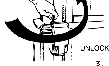
13 INSTALLATION OF THE OPERATORS 1. Fix the rear mount to the post or pillar according to the instructions in Table A. It may be necessary to adjust the length of the bracket. Warning: Observe the specified dimensions to ensure proper functioning. In the case of brick, stone, or concrete pillars, the bracket will need to be welded to a wall plate, which will then be drilled and fixed to the pillar. 2. Fix the ASTER to the rear mount using the pins and screw-plugs provided. Note that ASTER is provided in left and right hand versions. Left and right are determined by standing on the driveway looking toward the street. 3. Unlock the operator with the special key provided (1/2 turn in direction of arrow on casting near lock). 4. Extend the shaft to the end of its stroke. 5. Lock the operator with the key. 6. Rotate the extended shaft 1 full turn clockwise. The shaft will retract about 3/4 inch. 7. Fit the front mount with the pin and screw-plug provided. 8. Close the gate leaf against its limit stop and, keeping the operator perfectly horizontal, locate the attachment position of the front mount. 9. Fix the front mount temporarily with a clamp or vise-grip. 10. Again unlock the ASTER with the key, and ensure that the gate opens smoothly and that it stops on the travel limit stops, and that the telescoping shaft does not bottom out when fully retracted or fully extended. 11. Permanently attach the front mount to the horizontal member of the gate. If welding, detach the ASTER first to prevent splatter from damaging the stainless shaft. 12. Repeat the above operations for the second ASTER, if applicable.
14 INSTALLATION OF THE ELECTRONIC CONTROLLER Choose a convenient location for the controller. It can be surface mounted or recessed into the pillar or wall. If it is recessed, accurate planning is required in order for all conduits and wires to enter the controller's enclosure properly. In most cases, surface mounting is preferred. If the controller is located within reach of the power cord of the nearest ASTER, the cord can be routed directly into the control box without the need for an intermediate junction box. There are 2 knockouts in the bottom of the enclosure, one for high voltage wiring and one for low voltage. In some cases there may be no external low voltage wiring, and both knockouts can then be dedicated for high voltage conduits. Notice that there are 4 existing holes in the backside of the enclosure for mounting to any flat surface. Never drill holes through the enclosure as rainwater will enter the sealed area and possibly ruin the circuit board. If it is necessary to bring wires into the enclosure (other than through the knockouts), always enter at the bottom surface where the knockouts are located, and use a good sealant to prevent insects and water from entering the enclosure. An 8 uf capacitor for 220V or 25 uf capacitor for 110V are provided with each ASTER, and it is to be connected between the brown and black wires in the cord of each ASTER. An ideal location for this capacitor is inside the junction box where the ASTER's cord is spliced to the wires coming from the control unit. If there is a flap or "astragal" on one of the leaves in a two gate system, It must arrive at the closed position before the opposite leaf. An adjustable electronic delay is available for motor M2 only. When connecting the motor wires to the PM 8000 terminal strip, be certain to connect the wires from the motor on the gate with the astragal to M1, so that the delay on M2 affects the opposite leaf. When the gates are opened, the leaf with the astragal (Ml) will delay for 1 1/2 seconds. This opening delay is not adjustable. Follow the wiring diagrams with care, using 18 to 22-gauge wire for low voltage devices, and 14-gauge wire for the operators. Wires and cables should be rated for use in wet locations. If safety devices are not being used, the three positions of the terminal strip marked N.C. should be jumped to common. The three LED indicators (2 yellow, 1 red) above the terminal strip must be lighted before the system will operate. The 2 green LEDs are for the two positions marked N.O. They are normally dark.
15 CTR17-110V or CTR17-220V PM8000 Control Unit (main fuse for 110V is 10 amp, 220V is 5 amp, 24V out fuse is 2 amp)
16 CTR17-110V or CTR17-220V PM8000 Control Unit (main fuse for 110V is 10 amp, 220V is 5 amp, 24V out fuse is 2 amp) 110V or 220V Fuse Main power supply 220Vac 5 amp 110Vac 10amp
17
18 START-UP 1. Program the Electronic Controller to set the specific requirements of the system. See the accompanying sheet for detailed instructions. 2. Connect the system to the power supply and check that the green "Alimentazione" LED is lit. Check also that the two yellow and one red LEDs above the terminal strip are all lit. 3. Unlock each ASTER with the special key and move each leaf to its mid-point position. Relock each ASTER. 4. Provide the controller with a "start" signal via the remote controls or another device, and check that the gates begin to move. You should hear a rhythmic clicking of one of the relays within the controller. If the gates do not move, check that the trimmer on the torque adjustment card is set to its mid-point. Use a small 'jewellers' screwdriver. If the gate still does not move, check that the ASTER is locked and that the capacitor has been properly installed. 5. If one or both gates begin to close, disconnect the power and reverse the wires in the terminal strip labeled AP and CH for the motor which is closing. This will swap the positions of the brown and black wires of the operator, and will cause the Aster to reverse directions. 6. Re-connect the power and give the controller a start signal. Both gates should now open. Let them time-out before giving a close signal. Open and close the gates several times and check that the motors stay energized for a few seconds after they bump against their travel limit stops. Adjust trimmer "lavoro" and try again until the motors remain energised for about 3 or 4 seconds longer that it takes to effect a full opening or closing cycle. Changes to the trimmer 'lavoro' only take effect at the commencement of the next opening cycle. 7. In the case of overlapping leaves (one fitted with an astragal), it is possible to delay the closing of the leaf driven by motor M2. To adjust the delay time, set trimmer "SFASAM" so that the delayed leaf closes approx. 2 seconds after the opposite leaf. Start with the trimmer at the 9 o'clock position. 8. For gate systems that are configured to close automatically after a certain time has elapsed, trimmer "PAUSA" will set the delay time. Safety devices such as photobeams or vehicle detector loops MUST be fitted in such cases. 9. The Electronic Controller is fitted with an electronic anti-crushing safety system which limits the amount of thrust which can be exerted by the gates. When the obstacle is removed, the gate will again proceed until the set operation time has expired. To adjust the pressure that the gates can exert, use the trimmer on the torque adjustment card. Note that the speed of the gates can not be influenced by this adjustment. The dimensions A and B as referred to earlier determine gate speed. Always use the minimum amount of thrust, which will still move the gates reliably in all weather conditions. (eg. wind or cold temperatures) 10. Check that all hardware has been properly tightened, that the hinges are greased, and that all accessory devices are operating properly. Finally, check that the gasket is properly installed and the cover of the controller is securely fastened. Congratulations, you should now have completed your installation.
19 Example Elec Prep. Photo-beam located just outside of gates when closed. Power supply needs vary with voltage required by operator.
20 Example Elec Prep. Photo-beam located just outside of gates when closed. Power supply needs vary with voltage required by operator.
Linear Actuator Swing Gate Operator Installation Manual Model # LA405-24
 Linear Actuator Swing Gate Operator Installation Manual Model # LA405-24 2 Contents Contents Product Information and Specs. 3 Mechanical 3 Electrical, Line Connections 3 Electrical, Control Connections
Typical Installation Schematic
 The 760 Gate Automation System The FAAC 760 automation system consists of a monoblock hydraulic unit and foundation box assembly. The system is designed for underground installation, and will not alter
Installation and Maintenance Manual
 Installation and Maintenance Manual Swing Gate Operator Model HL410-21 & HL410L-21 2 Contents Contents Parts & Components 3 Specifications & Capacities 4 Safety Information 6 Installer 6 End User 7 General
SWING GATE OPENERS 24V DC GEAR MOTOR
 SWING GATE OPENERS 24V DC GEAR MOTOR FOR RESIDENTIAL USER MANUAL Flashing Light Push Button Control box Gate 2 Gate 1 Index 1. Warnings 2 4. Technical Characteristics 16 2. Product Description 2.1 Applications
Instruction Manual for the. E-SL 450 Series
 Instruction Manual for the E-SL 450 Series Estate Slide Summary of Functions The Estate Slide is only to be used for vehicular Slide gates in a Class I setting. Class I: A vehicular gate opener (or system)
Automation Swing Gate Opener
 Automation Swing Gate Opener Operating and installation instructions SP EIFFEL 400 V1.0 Rev 08/01 CONTENTS 0) GENERAL SAFETY REGULATIONS...Page 0 1) DESCRIPTION...Page 03 ) TECHNICAL SPECIFICATIONS 3)
LI-2B Installation Manual
 ARCO Pty. Ltd. LI-2B Intelligent Gate Controller Installation/Owners Manual Please do not commence installation until you have read this instruction book. Contents: Introduction Installation Options: Standard
PW320/PW330 USER MANUAL SWING GATE OPENERS 24V DC GEAR MOTOR FOR RESIDENTIAL. Flashing Light. Push Button. Control box. Gate 2.
 PW320/PW330 USER MANUAL SWING GATE OPENERS 24V DC GEAR MOTOR FOR RESIDENTIAL Flashing Light Push Button Control box Gate 2 Gate 1 Declaration of Conformity Applicant: Powertech Electronics Inc. Manufacturer:
PW150/PW200 USER MANUAL SWING GATE OPENERS 24V DC GEAR MOTOR
 PW150/PW200 USER MANUAL SWING GATE OPENERS 24V DC GEAR MOTOR FOR RESIDENTIAL Flashing Light Push Button Control box Declaration of Conformity Applicant: Powertech Electronics Inc. Manufacturer: Timotion
ACSI MODEL 1440 POWER SUPPLY INSTALLATION INSTRUCTIONS
 II 1400-8 Features: ACSI MODEL 1440 POWER SUPPLY INSTALLATION INSTRUCTIONS Filtered/Regulated 24 Volts DC Up to Full 2 Amps Load Capacity Class 2 Rated Outputs Overload, Over Voltage, and Short Circuit
is250/is250d/is250solar SWING GATE OPENER MANUAL
 is250 / is250d / is250solar SWING GATE OPENER USER MANUAL INDEX 1.1 GENERAL SAFETY PRECAUTION...P.1 1.2 INSTALLATION A. STANDARD INSTALLATION...P.2 B. INSTALLATION CHECK...P.3 C. REAR BRACKET INSTALLATION...P.4
Installing the gate post bracket with the cardboard arm template
 ......... Installing the gate post bracket with the cardboard arm template... Installing gate posts brackets and arms for Push-to-Open or Pull-to-Open gates... Connection of Power Source 240Vac or Solar...
EC MACHINE DIRECTIVE COMPLIANCE DECLARATION
 EC MACHINE DIRECTIVE COMPLIANCE DECLARATION (DIRECTIVE 89/392 EEC, APPENDIX II, PART B) Manufacturer: FAAC S.p.A. Address: Via Benini, 1 40069 - Zola Predosa BOLOGNA - ITALY Hereby declares that: the 770
2904 Power Supply Installation Instructions I-EA00041
 FEATURES Controls an opening with electrified locking device and automatic door operator Separate inputs for activation switch on entry and exit sides of opening Separate 24 VDC outputs for fail safe and
Gate Operators, Inc. Model 7100UL Residential & Medium Duty Commercial Slide Gate Operator INSTALLATION MANUAL
 Gate Operators, Inc. Model 7100UL Residential & Medium Duty Commercial Slide Gate Operator INSTALLATION MANUAL 10-04-00 CONTENTS Safety Precautions... 2 Applications... 3 Pre-Installation Checklist...
Installing the gate post bracket with the cardboard arm template
 ......... Installing the gate post bracket with the cardboard arm template... Installing gate posts brackets and arms for Push-to-Open or Pull-to-Open gates... Connection of Power Source 240Vac or Solar...
Model 1550 Single Swing Gate Model 1650 Dual Swing Gate
 Gate Operators, Inc. Model 1550 Single Swing Gate Model 1650 Dual Swing Gate Swing Gate Operator CONTENTS Safety Precautions... 2 Applications... 3 Pre-Installation Checklist... 4 Parts Identification...
FROG KIT. Installation Instructions for a Pair of gates... TECHNICAL HELPLINE THE FROG-P KIT CONSISTS OF:
 CAME UNITED KINGDOM LTD UNIT 3 ORCHARD PARK INDUSTRIAL ESTATE, TOWN STREET, SANDIACRE, NOTTINGHAM NG10 5BP TEL: 0115 921 0430 FAX: 0115 921 0431 TECHNICAL HELPLINE 0115 921 0430 INTERNET - www.cameuk.com
SLIDING GATE OPENER USER MANUAL
 is600 / is900solar24 SLIDING GATE OPENER USER MANUAL Bluetooth charge monitoring app INDEX 1.1 GENERAL SAFETY PRECAUTION 1.2 KIT CONTENTS.. P.1 P.2 1.3 DIMENSION... P.3 1.4 TECHNICAL FEATURES P.4 1.5 INSTALLATION
HYDRAULIC SWING GATE OPENER
 is320 / is320d HYDRAULIC SWING GATE OPENER USER MANUAL INDEX 1.1 GENERAL SAFETY PRECAUTION...P.1 1.2 INSTALLATION A. INSTALLATION CHECK...P.2 B. BRACKET MOUNTING DIMENSIONS...P.3 C. INSTALLATION...P.4
Easy/Tran TF STANDBY POWER FURNACE SWITCH TOOLS NEEDED FOR INSTALLATION. PARTS LIST for Easy / Tran TF FURNACE TRANSFER SWITCH
 STANDBY POWER FURNACE SWITCH Easy/Tran TF Congratulations on your purchase of the Reliance Controls Easy/Tran TF furnace transfer switch. Reliance has been manufacturing transfer switches and equipment
D Vers. 03 ELECTROMECHANICAL AUTOMATION FOR SWING GATES
 E5 D811007 15-09-99 Vers. 03 ELECTROMECHANICAL AUTOMATION FOR SWING GATES 122 This product complies with recognised technical standards and safety regulations. We declare that this product is in conformity
LINCE 300/400/600. User s and Intaller s manual
 LINCE 300/400/600 User s and Intaller s manual v1.0 REV. 09/2013 00. CONTENT 01. SAFETY INSTRUCTIONS INDEX STANDARDS TO FOLLOW 00. CONTENT Index page 01.A 01. SAFETY INSTRUCTIONS Standards to follow page
TMT Boxer 24v slider motor installation notes from EasyGate
 TMT Boxer 24v slider motor installation notes from EasyGate Install Physical Gate Stops Physical Gate Stops MUST be installed at each end of your gate. If the Limit Switch on the boxer motor fails to stop
AgriWheel Single Gate Kit Low Voltage & Solar. Installation & Operating Instructions
 AgriWheel Single Gate Kit Low Voltage & Solar Installation & Operating Instructions Thank you for purchasing you AgriWheel system. Please remove the lids from both the machine and control box and remove
PowerMaster MODEL MBG. Installation Manual U L R UL 325 AND UL 991 LISTED MEDIUM DUTY BARRIER GATE OPERATOR TABLE OF CONTENTS
 PowerMaster TABLE OF CONTENTS MODEL MBG MEDIUM DUTY BARRIER GATE OPERATOR Important Safety Information...... 3 System Designer Safety Instructions.......4 Installer Safety Instructions....... 5 Installation
EC MACHINE DIRECTIVE COMPLIANCE DECLARATION
 770 EC MACHINE DIRECTIVE COMPLIANCE DECLARATION (DIRECTIVE 89/392 EEC, APPENDIX II, PART B) Manufacturer: FAAC S.p.A. Address: Via Benini, 1 40069 - Zola Predosa BOLOGNA - ITALY Hereby declares that: the
Section A1. Vehicular Gate Operators. This Price Schedule is effective June 1, Date Page Comment All June, 2016 Price Schedule update.
 June 2016 PRICE SCHEDULE A 2.0 Section A1 This Price Schedule is effective June 1, 2016. Date Page Comment 6-1-16 All June, 2016 Price Schedule update. Prices and specifications subject to change without
INSTALLATION AND OPERATING INSTRUCTIONS
 INSTALLATION AND OPERATING INSTRUCTIONS MANUAL TRANSFER SWITCHES FROM 0 Residential Wattage Requirements Appliance Running Watts Add watts for starting Furnace blower, gas or fuel 1/8 hp 300 500 1/8 hp
F ERNI K I T THE FERNI-S KIT CONSISTS OF:
 CAME UNITED KINGDOM LTD ORCHARD PARK INDUSTRIAL ESTATE TOWN STREET, SANDIACRE, NOTTINGHAM, NG10 5BP TEL: 0115 921 0430 FAX: 0115 921 0431 INTERNET - www.cameuk.com E-MAIL - enquiries@cameuk.com TECHNICAL
6002 swing gate actuator - installation guide
 600 swing gate actuator - installation guide 600 Residential Swing Gate Actuator Installation Guide DKS DoorKing, Inc. 0 Glasgow, Avenue Inglewood, Ca. 900 0.645.00 0.64.586 fax info@doorking.com www.doorking.com
FM200 FLOW/NO-FLOW MONITOR INSTALLATION AND TECHNICAL MANUAL 120 VAC MODEL 6/1/2017
 FM200 FLOW/NO-FLOW MONITOR INSTALLATION AND TECHNICAL MANUAL 120 VAC MODEL 6/1/2017 Maxi-Tronic, Inc. 417 Wards Corner Road Loveland, OH 45140 513.398.2500 800.659.8250 FAX: 513.398.2536 info@maxitronic.com
Porte 150 Users Manual Swing Gate Opener 24V DC
 Porte 150 Users Manual Swing Gate Opener 24V DC for residential use only Signal Light Push-button Control Box 14 Contents 1. Important Safety Information 2. Product Description and Application 2.1 Application
Installation manual ASTER AUTOMATION FOR SWING GATES 11_16
 Installation manual ASTER AUTOMATION FOR SWING GATES 11_16 Contents 1. GENERAL SAFETY PRECAUTIONS... page 01 2. INTENDED USE AND APPLICATION... page 01 2.1 Kit contents... page 01 2.2 Technical features...
INSTRUCTIONS FOR INSTALLATION
 HYDRAULIC OPERATOR MODO 110-110/L FOR SINGLE- OR DOUBLE-WING SWING GATES INSTRUCTIONS FOR INSTALLATION GENERAL WARNINGS These warnings constitute an integral and essential part of the product and must
Milwaukee's Electric Actuator Installation, Operation & Maintenance Manual
 Milwaukee's Electric Actuator Installation, Operation & Maintenance Manual 1 Cover screws 9/64 Allen wrench. Terminal strip screws 1/8 wide flat head screw driver. Mounting pad screws 3/8 socket Cover
IRREVERSIBLE OPERATOR FOR SWING GATES AND DOORS
 VH IRREVERSIBLE OPERATOR FOR SWING GATES AND DOORS WARNING!! Before installing, thoroughly read this manual that is an integral part of the pack Our products if installed by qualified personnel capable
MODEL D-SBG Single Arm Barrier Gate Operator
 INSTALLATION AND OWNER S MANUAL MODEL D-SBG Single Arm Barrier Gate Operator UL 325 and UL 991 Listed WITH NITRO BOARD (SEE SUPPLEMENTAL MANUAL) Serial #: Date Installed: Your Dealer: READ THIS MANUAL
ARTICULATED ARM GATE OPENER USER MANUAL
 is270 / is270d / is270solar ARTICULATED ARM GATE OPENER USER MANUAL INDEX 1.1 GENERAL SAFETY PRECAUTION...P.1 1.2 INSTALLATION A. STANDARD INSTALLATION...P.2 B. INSTALLATION CHECK...P.3 C. COMPONENTS FOR
Owner's/Installation Manual
 Owner's/Installation Manual Power Management Module (PMM) and Starter Kit NOTE: The starter kit must be purchased and installed prior to individual PMM usage. Model Numbers: 00686-0 PMM 00699-0 PMM WITH
MASTIFF 300/300M SWING GATE OPENER USER MANUAL
 MASTIFF 300/300M SWING GATE OPENER USER MANUAL INDEX 1.1 GENERAL SAFETY PRECAUTION 1.2 INSTALLATION A. STANDARD INSTALLATION B. DIMENSION CHART C. MOTOR FIXING D. WIRE CONNECTION E. EMERGENCY RELEASE F.
DKC400Y AC Sliding Gate Installation Manual. Sliding Gate Opener. Model: DKC400Y. Installation Manual WARNING
 Sliding Gate Opener Model: DKC400Y Installation Manual WARNING Read and thoroughly understand all instructions before installing or operating this automatic gate opener. Failure to do so may cause serious
IMPORTANT SAFETY RECOMMENDATIONS
 801-001-01 C IMPORTANT SAFETY RECOMMENDATIONS FAILURE TO COMPLY WITH THE FOLLOWING SAFETY RECOMMENDATIONS MAY RESULT IN SERIOUS PERSONAL INJURY AND/OR PROPERTY DAMAGE. 1. For ADDITIONAL SAFETY we STRONGLY
HIGH SPEED SLIDING GATE OPENER
 HIGH SPEED SLIDING GATE OPENER Model: is1200 + Elsema s Eclipse Control Card with GDS Operator USER MANUAL CONTENTS Section No: Page No: 1 Safety Precautions 3 2 Wiring Requirements 4 3 Installation details
READ AND FOLLOW ALL SAFETY INSTRUCTIONS SAVE THESE INSTRUCTIONS
 5 Swift Lock Ready Shape Tree (Patent Pending) Instructions IMPORTANT SAFETY INSTRUCTIONS When using electrical products, basic precautions should always be followed including the following: READ AND FOLLOW
INSTRUCTIONS FOR THE RELIANCE CONTROLS ARM SERIES AUTOMATIC TRANSFER SWITCH
 INSTRUCTIONS FOR THE RELIANCE CONTROLS ARM SERIES AUTOMATIC TRANSFER SWITCH THE RELIANCE CONTROLS ARM SERIES AUTOMATIC TRANSFER SWITCH IS NOT FOR "DO-IT-YOURSELF" INSTALLATION. It must be installed by
Series BFM Bulk Flow Monitor 1A FUSE RED LED RELAY. Part Number BFM-1 BFM-2 BFM-3 BFS-1
 Series Bulk Flow Monitor Specifications - Installation and Operating Instructions Bulletin FL-1-4x 3/4 CONDUIT KNOCKOUTS BFS 1A FUSE RED LED RELAY 5-9/64 [130.45] TRANSFORMER 3[76.20] GREEN LED 7 [177.80]
ELECTRO-MECH SCOREBOARD CO.
 ELECTRO-MECH SCOREBOARD CO. MM-338 FOOTBALL SCOREBOARD OWNER S HANDBOOK Thank you for choosing an Electro-Mech Scoreboard for your athletic complex. We are confident that your new scoreboard will give
INSTALLATION INSTRUCTION W Track Recessed 120V Flangeless
 W Track Recessed 120V Flangeless WT4-RTL, WT8-RTL, WT12-RTL SAFETY INSTRUCTION Read all of these instructions before installing the track system. Turn off power at main switch before installing or modifying
Sliding Gate Operator User's Manual
 Sliding Gate Operator User's Manual PY800AC/PY00AC. Products introduction Please read the instructions carefully before proceeding. MCU is supplied to control the gate operator. Keypad / single button
Model 400. Opening a Whole New World: FAAC Swing Gate Systems SWEETS UL 325 COMPLIANT CSI # Gate Operators
 Look for us in SWEETS 2006 landscape architect directory and at: www.sweets.com Opening a Whole New World: FAAC Swing Gate Systems Model 400 The Model 400 is specifically designed for situations needing
INSTALLATION INSTRUCTIONS & MANUAL BOOK FOR ARCHITECTS, GENERAL CONTRACTORS & DEALERS REV-2
 INSTALLATI INSTRUCTIS & MANUAL BOOK FOR ARCHITECTS, GENERAL CTRACTORS & DEALERS REV-2 C Applied Applied MODEL: MIRACLE 1 HIGH-QUALITY, MECHANICAL, LINEAR OPERATOR FOR SWING GATES COPYRIGHT 1998 ELITE ACCESS
Contents. EC DECLARATION OF CONFORMITY FOR MACHINES... p. 10. WARNINGS FOR THE INSTALLER... p. 10
 Contents EC DECLARATION OF CONFORMITY FOR MACHINES... p. 10 WARNINGS FOR THE INSTALLER... p. 10 1. DESCRIPTION AND TECHNICAL SPECIFICATIONS... p. 11 1.1. DIMENSIONS... p. 11 2. ELECTRIC DEVICES (standard
PERSA 400 USER S AND INSTALLER S MANUAL V1.0 REV. 10/2016
 PERSA 400 USER S AND INSTALLER S MANUAL V1.0 REV. 10/2016 00. CONTT 01. SAFETY INSTRUCTIONS INDEX 01. SAFETY INSTRUCTIONS STANDARDS TO FOLLOW 02. PACKAGE INSIDE PACKAGE 03. OPERATOR TECHNICAL SPECIFICATIONS
YG101 SWING GATE OPENER OWNER S MANUAL
 YG101 SWING GATE OPENER OWNER S MANUAL IMPORTANT SAFTEY INFORMATION Installing the YG101 Gate Opener requires wiring of standard 110V electrical lines. This should only be performed by a trained technician.
APOLLO Gate Operators, Inc.
 APOLLO Gate Operators, Inc. Model 3500ETL/3600ETL Commercial Swing Gate Operator INSTALLATION MANUAL 01/08 CONTENTS IMPORTANT SAFETY INSTRUCTIONS. 3 Applications... 4 Pre-Installation Checklist... 5 Parts
Arnberg Industries & It s Partners are not responsible for any damage or injury caused by correct or incorrect installation of this transfer switch.
 3560 NE ROZENE WAY BREMERTON, WASHINGTON 98311 (530) 316-1049 Generator Transfer Switch Model; HTS15-MAN & HTS15-MAN-2 Tools Needed For Installation Power drill Wire stripper and cutter (10 to 14 gauge)
3143 Production Drive Fairfeild, Ohio Model HA Installation and Service Manual
 3143 Production Drive Fairfeild, Ohio 45014 513-874-3733 Model HA-1000 Installation and Service Manual 3143 Production Drive Fairfeild, Ohio 45014 513-874-3733 Model HA-1000 Installation and Service Manual
Installation and Set Up Instructions
 Model FG 5-7 / SW 5-7 / DSW 5-7 Swing Gate Motor Kit Solar powered and 12V Low Voltage Installation and Set Up Instructions Unit 27 / 49 Corporate Boulevard Bayswater Vic 3153 Phone 1800 111 930 Email
Installation and Set Up Instructions
 SL 2000 DC2 SLIDING GATE MOTOR KIT Solar Powered and 12V Low Voltage Installation and Set Up Instructions Unit 27 / 49 Corporate Boulevard Bayswater Vic 3153 Phone 1800 111 930 Email info@gforceautogates.com.au
INSTALLATION INSTRUCTIONS
 INSTALLATION INSTRUCTIONS WARNING: WARNING: www.altronicinc.com DEVIATION DEVIATION FROM THESE FROM INSTRUCTIONS THESE INSTRUCTIONS MAY LEAD MAY TO LEAD IMPROPER TO IMPROPER OP- ERATION OF ENGINE THE MACHINE
VEHICULAR AC & DC. Residential Apartment/College Residence Halls Gated Communities Mixed Use Buildings Commercial/Industrial Parking Self Storage
 VEHICULAR AC & DC SWING GATE OPERATORS Residential Apartment/College Residence Halls Gated Communities Mixed Use Buildings Commercial/Industrial Parking Self Storage AC & DC POWERED Gate OPERATORS Safety
Next, chase the threads in the lower A-arm mounts with the 5/8-18 tap and blowout any remaining particles.
 Next, chase the threads in the lower A-arm mounts with the 5/8-18 tap and blowout any remaining particles. Now, apply some anti-seize to the threads of the pivot stud. Also put anti-seize inside the bore
Installation manual. English. mystrike OPENER FOR RACK-DRIVEN SLIDING MOTOR
 Installation manual English mystrike OPENER FOR RACK-DRIVEN SLIDING MOTOR 1. WARNINGS AND GENERAL SAFETY INSTRUCTIONS This manual contains important safety information. An incorrect installation or an
Installation and Set Up Instructions
 SL SLIDING GATE MOTOR KIT Solar Powered and 12V Low Voltage Installation and Set Up Instructions Unit 27 / 49 Corporate Boulevard Bayswater Vic 3153 Phone 1800 111 930 Email info@gforceautogates.com.au
Sliding Gate Operator User's Manual
 Sliding Gate Operator User's Manual SL600AC. Products introduction Please read the instructions carefully before proceeding. MCU is supplied to control the gate operator. Keypad / single button interface.
FITTING AND CONNECTION INSTRUCTIONS
 LEPUS is an oil-bathed motor-reducer created for sliding gates automation. The motor-reducer irreversibility allows a perfect and safe gate closing avoiding the setup of an electrolock and in case of power
Buffalo America C Column Mountable Gate Opener WARNING
 Column Mountable Gate Opener WARNING Read all instructions before beginning installation or use of this gate opener. This operator exerts a high level of force. Exercise caution at all times and stay clear
Installation Instructions
 Installation Instructions MX3635-01 Rev. E Models HydraSwing 40s HydraSwing 40F 4,000 lb (1,814 kg) 10-15 seconds HydraSwing 40 4,000 lb (1,814 kg) 15-20 seconds HydraSwing 40 Twin 4,000 lb (1,814 kg)/leaf
PBA Series Prelube Controls
 VARNA Products Engineered Innovation PBA Series Prelube Controls Simple, Compact, Industrial Full featured control for running prelube from the control or from a remote station Easy internal wiring connections
Actuator Arm and Control Box Mounting
 Actuator Arm and Control Box Mounting To wire this operator and complete the installation, refer to a specific control box Wiring/Owner s manual. 6002 Vehicular Swing Gate Operator 6002-065-Y-1-13 Copyright
Product Manual MNX10015 / REV B MODEL SB142, SB242. Dual Output Series Switch Boxes
 Product Manual MNX10015 / REV B MODEL SB142, SB242 Dual Output Series Switch Boxes Contents Section I Overview Introduction.... 2 Description... 2 Section II Installation Mounting... 3 Electrical Connections...
E-SL 450BD Series INSTRUCTION MANUAL WARNING USER DRIVEN MANUAL*
 USER DRIVEN MANUAL* Any feedback, changes, or advice we are glad to hear it. Please contact us at support@estateswing.com WARNING Read all instructions before beginning installation or use of this gate
READ AND FOLLOW ALL SAFETY INSTRUCTIONS SAVE THESE INSTRUCTIONS
 7.5 Swift Lock Ready Shape Tree (Patent Pending) Instructions IMPORTANT SAFETY INSTRUCTIONS When using electrical products, basic precautions should always be followed including the following: READ AND
INSTALLATION AND OWNER S MANUAL MODEL ASW Actuator Swing Gate Operator
 INSTALLATION AND OWNER S MANUAL MODEL ASW Actuator Swing Gate Operator Serial #: Date Installed: Your Dealer: READ THIS MANUAL CAREFULLY BEFORE INSTALLATION OR USE. SAVE THESE INSTRUCTIONS. Introduction
JEEVES. JEEVES Installation Manual. Installation Manual The Easiest Do-It-Yourself Dumbwaiter on the Market
 1 888-323-8755 www.nwlifts.com JEEVES Installation Manual The Easiest Do-It-Yourself Dumbwaiter on the Market This manual will cover the installation procedure step-by-step. The installation of this dumbwaiter
SWING GATE OPENERS 24V DC GEAR MOTOR
 SWING GATE OPENERS 24V DC GEAR MOTOR FOR RESIDENTIAL USER MANUAL Flashing Light Push Button Control box Gate 2 Gate 1 Index Warnings 2 5. Technical Characteristics 21 1. Product Description and Applications
CHUBBSAFES EVOLVE INSTRUCTION MANUAL
 CHUBBSAFES EVOLVE INSTRUCTION MANUAL 1 Ref: BASS-0010-B/21.02.2014 Table of content 1- CHARACTERISTICS... 4 1-1 Models... 4 1-2 Dimensions & Weights... 4 1-3 Interior fittings (standard and optional)...
#366. Gate Operator Pre-Installation and Site Planning. Introduction
 Gate Operator Pre-Installation and Site Planning Introduction Although each manufacturer s equipment has unique design characteristics and functions, gate operators are somewhat similar in many installation
Installation Manual E8-400 E8-500 E Solar or Electric Systems
 Installation Manual E8-400 E8-500 E8-600 Solar or Electric Systems 1 WARNING Important Safety Information Gate equipment has hazards associated with its use and therefore by installing this product the
Please DO NOT Touch me!... Unless you are an Authorized Service Technician!
 V 0503 TABLE OF CONTENTS N T Attention: This handbook is exclusively for qualified installation personnel, and assistance and/or maintenance service. - The performances indicated in this handbook are valid
Inteli-Lift GEN II DUMBWAITER
 1 877-345-4387 530-295-4900 www.eilifts.com Inteli-Lift GEN II DUMBWAITER The Easiest Dumbwaiter system on the Market Fully UL Certified Dumbwaiter Systems UL File # SA32120 This manual will cover the
ACSI MODEL 1406BB-04-AO POWER SUPPLY INSTALLATION INSTRUCTIONS
 II 1400-10 ACSI MODEL 1406BB-04-AO POWER SUPPLY INSTALLATION INSTRUCTIONS Features: Up to 1.95 Amps Load Capacity Class 2 Rated Outputs Overload, Over Voltage, and Short Circuit Protection Standby Battery
SECTION HYDRAULIC FOUR FOLD DOORS MODEL 48 LOUVERS
 SECTION 08350 HYDRAULIC FOUR FOLD DOORS MODEL 48 LOUVERS PART 1 GENERAL 1.01 RELATED DOCUMENTS A. Drawings and general provisions of the Contract, including General and Supplementary Conditions and Division-1
 Access Blue Boom support@et.co.za 0860 109 238 G&C Electronics cc. T/A ET Systems 15 Nelson Rd, Observatory, Cape Town, South Africa www.et.co.za Technical specifications may change without prior notice.
EstateSwing.com. Plug-in Option. E-S 1000H Series INSTRUCTION MANUAL
 EstateSwing.com Plug-in Option E-S 1000H Series INSTRUCTION MANUAL Estate Swing Summary of Functions The Estate Swing is only to be used for vehicular swing gates in a Class I setting. Class I: A vehicular
Technical Manual. DLM Module. This manual should remain with the unit.
 Technical Manual DLM Module This manual should remain with the unit. Safety Rules SAVE THESE INSTRUCTIONS! Read the following information carefully before attempting to install, operate or service this
MASTERsine Inverter PXA Series Installation Guide
 Backup Power System Expert TM MASTERsine Inverter PXA Series Installation Guide Important Safety Instructions IMPORTANT: Read and save this Installation Guide for future reference. This chapter contains
GENERAL SAFETY... 3 PARTS LIST...
 Rev 17a 1 GENERAL SAFETY... 3 PARTS LIST... 4 GTR100... 4 GTR058... 5 TECHNICAL SPECIFICATIONS... 6 FEATURES:... 6 QUICK INSTALLATION GUIDE... 7 GATE ARM INSTALLATION... 8 BEFORE YOU START... 8 INSTALLATION
The POWER. In PRESENTATION PRODUCTS. Instruction Book for COSMOPOLITAN ELECTROL For Sizes Up To 9'x12' DA-LITE SCREEN COMPANY, INC.
 The POWER In PRESENTATION PRODUCTS Instruction Book for COSMOPOLITAN ELECTROL For Sizes Up To 9'x12' DA-LITE SCREEN COMPANY, INC. 3100 North Detroit Street Post Office Box 137 Warsaw, Indiana 46581-0137
CSA CERTIFIED Conforms to UL 507
 Installation tion Instructions Please read and save these instructions! TURBO/MAXX12 Volt All Weather RV Ventilator Fans P/N 00-965001 Deluxe Model 1200T WITH THERMOSTAT P/N 00-965007 Standard Model 3550
FOR INDOOR/SEASONAL USE ONLY
 9' Warm White /Multi LED Color Changing One Plug Tree V66362-60 INSTRUCTION MANUAL Thank you for purchasing a SYLVANIA Pre-lighted Tree. This tree assembles in minutes and is decorated with energy saving
GLM SERIES CONTROL Users Manual Rev:
 GLM SERIES CONTROL Users Manual Rev: 808062 Connecting Power Page 2 Motor Terminal Wiring Diagrams Page 3 Getting Started / Setup Page 4 1. Obstruction Detection Devices Page 4 2. Checking Power and Direction
Table of Contents. General Safety Preparation for Installation Parts List Optional Accessories Part List... 5
 REV 12a Table of Contents General Safety....... 2 Preparation for Installation....... 3 Parts List....... 4 Optional Accessories Part List...... 5 Technical Specifications & Feature...... 5 Installation
INSTALLATION M ANUAL
 INSTALLATION MANUAL Table of Contents UL Listings Installing the Warning Sign / Precautions Methods of Installation / Compact Installation Mounting the Secondary Entrapment / Welding Gate Arn Mounting
TECHNICAL DATA HYDRAULIC UNIT
 GB INSTRUCTIONS MANUAL RISING BOLLARD OIL-HYDRAULIC AUTOMATION COMPONENTS strabuc 918 RELEASE KEY PLUG FOR RELEASE HOLE BOLLARD COVER 12 V WARNING LIGHTS REFLECTORS COMPLETELY RETRACTABLE POST WITH ELECTROPHORESIS
MEKO OPENER FOR RACK-DRIVEN SLIDING MOTOR
 Installation Manual MEKO OPENER FOR RACK-DRIVEN SLIDING MOTOR 02_2016 1. WARNINGS AND GENERAL SAFETY INSTUCTIONS This manual contains important safety information. An incorrect installation or an improper
INSTALLATION INSTRUCTIONS For Light*Waves Flex II Kit with 300-Watt remote transformer
 IMPORTANT SAFETY INSTRUCTIONS READ ALL OF THESE BEFORE INSTALLING THE TRACK SYSTEM. SAVE THESE INSTRUCTIONS AND REFER TO THEM WHEN ADDITIONS TO OR CHANGES TO THE SYSTEM ARE MADE. THIS IS A 12-VOLT SYSTEM
METROLOGIC INSTRUMENTS, INC. MX001 Industrial Control Interface Installation and User s Guide
 METROLOGIC INSTRUMENTS, INC. MX001 Industrial Control Interface Installation and User s Guide Copyright 2007 by Metrologic Instruments, Inc. All rights reserved. No part of this work may be reproduced,
EXTREME R MOTOR OWNER'S MANUAL
 EXTREME R MOTOR OWNER'S MANUAL 2 HP, 3 HP & 5 HP WITH SELF-ENGAGING CHAIN HOIST FOR TECHNICAL SUPPORT PLEASE CALL 1-(855) 594-4969 3137B(0) ECN 1313 BY JM 7/9/15 OPERATOR SERIAL# PRO-FDG MOTOR OPERATORS