Table of Contents. General Safety Preparation for Installation Parts List Optional Accessories Part List... 5
|
|
|
- Shona Stevens
- 5 years ago
- Views:
Transcription

1 REV 12a
2 Table of Contents General Safety Preparation for Installation Parts List Optional Accessories Part List Technical Specifications & Feature Installation Overview Installation of the Operator Manual Operation Fit the plastic rack reinforced with steel.. 8 Installation of the Limit Switch Connecting Of Power Supply Connecting of the Control Board Setting of the Control Board Test the reversing sensitivity How to learn or erase the remote How to use the remote to control the operator.. 14 Trouble Shooting Maintenance

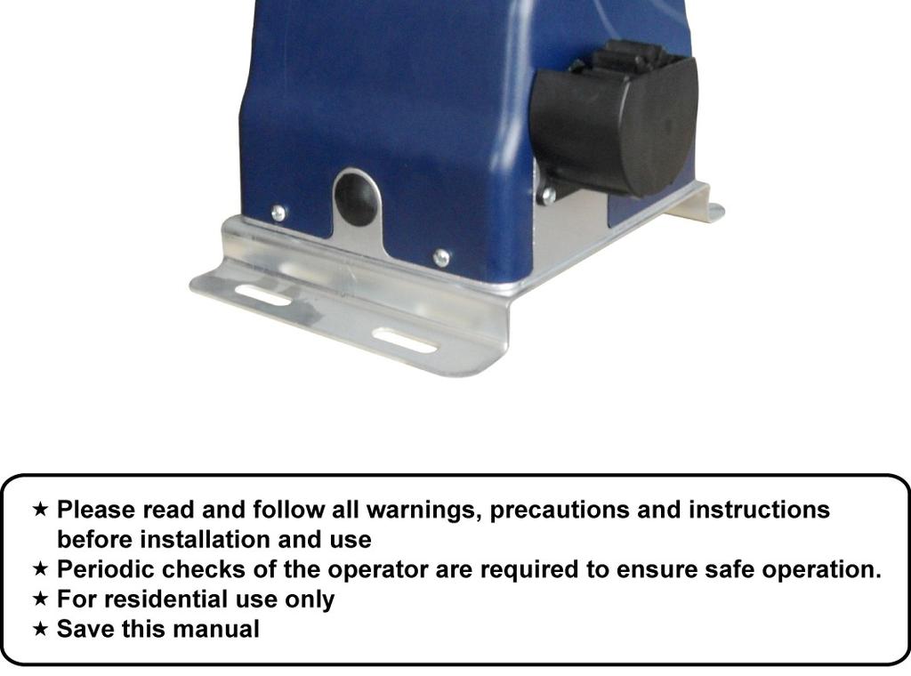
3 Thank you for purchasing DSR400 sliding gate operator. We are sure that the products will be greatly satisfying as soon as you start to use it. The product is supplied with a user s manual which encloses installation and safety precautions. These should be read carefully before installation and operation as they provide important information about safety, installation, operation and maintenance. This product complies with the recognized technical standards and safety regulations. General Safety WARNING! An incorrect installation or improper use of the product can cause damage to persons, animals or properties. Scrap packing materials (plastic, cardboard, polystyrene etc.) according to the provisions set out by current standards. Keep nylon or polystyrene bags out of children s reach. This product was exclusively designed and manufactured for the use specified in the present documentation. Any other use not specified in this documentation could damage the product and be dangerous. The factory declines all responsibility for any consequences resulting from improper use of the product, or use which is different from that expected and specified in the present documentation. Do not install the product in explosive atmosphere. The factory declines all responsibility for any consequences resulting from failure to observe Good Technical Practice when constructing closing structures (door, gates etc.), as well as from any deformation which might occur during use. Disconnect the electrical power supply before carrying out any work on the installation. Also disconnect any buffer batteries, if fitted. Fit an omnipolar or magnetothermal switch on the mains power supply, having a contact opening distance equal to or greater than 3,5 mm. Make sure a residual current circuit breaker with a 30mA threshold is fitted before the power supply mains. Check that earthing is carried out correctly: connect all metal parts for closure (doors, gates etc.) and all system components provided with an earth terminal. Fit all the safety devices (photocells, electric edges etc.) which are needed to protect the area from any danger caused by squashing, conveying and shearing. Position at least one visible indication device (Alarm lamp), and fix a Warning sign to the structure. The factory declines all responsibility with respect to the automation safety and correct operation when other supplier s components are used. Only use original parts for any maintenance or repair operation. Do not modify the automation components, unless explicitly authorized by the factory. Instruct the product user about the control systems provided and the manual opening operation in case of emergency. 2

4 Do not allow persons or children to remain in the automation operation area. Keep radio control or other control devices out of children s reach, in order to avoid unintentional automation activation. The user must avoid any attempt to carry out work or repair on the automation system, and always request the assistance of qualified personnel. Anything which is not expressly provided for in the present instructions is not allowed. Before installing the gate opener, check that all moving part as well as the sliding gate is in good mechanical condition, correctly balanced and opens and closes properly. Save these instructions for future use. Preparation for Installation Before proceeding to your operator installation, check if your gate structure is in accordance with the current standards, especially as follows: The gate sliding track is linear and horizontal, and the wheels are suitable,the gate should be mounted and moving freely. Check that the structure is sufficiently strong and rigid, and that its dimensions and weights conform to those listed in the specifications table of this document. Make sure that the gate is plumb and level. The fence posts must be mounted in concrete. The gate does not bind or drag on the ground. The gate manual operation can be carried out smoothly along its entire run, and there is no excessive side slipping. The opening and closing gate stops are positioned. WARNING: Remember that control devices are intended to facilitate gate operation, but can not solve problems due to any defects or deficiency resulting from failure to carry out correct installation or maintenance. Take the product out of its packing and inspect it for damage. Should it be damaged, contact your dealer. Remember to dispose of its components (cardboard, polystyrene, nylon, etc.) according to the current prescriptions. Refer to the following Figures for gate installation. In sake of safety, a positive stop must be mounted on the two end of ground track. 3

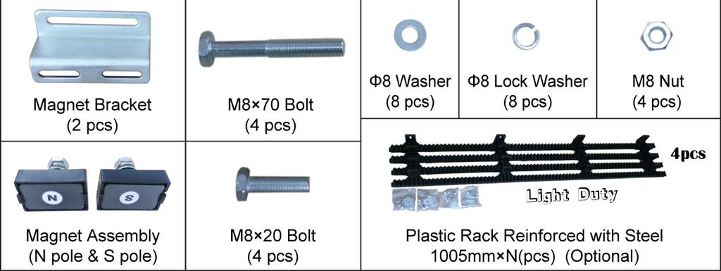
5 Parts List 4


6 Optional Accessories Parts List Technical Specifications & Features Specifications Power supply: 120V/60HZ or 230V/50HZ Motor: 24VDC Absorbed power: 120W Gate moving speed: (7 /second) 18 cm/second Max gate weight: 400KGS Max torque: 8Nm Environmental conditions: from -15 C to +40 C Protection class: IP44 5 REV 12a

7 Dimensions: CM Features: Soft start and soft stop Midway mode Easy to install and low maintain Quick selection for the gate open/close direction Reliable rolling code technology Emergency release key in case of power failure Stop/Reverse in case of obstruction during gate opening/closing Built in adjustable auto-close (0, 30, 60, 90 seconds) Built in max. 90 seconds Motor running time (MRT) for multiple safety protection Reliable electromagnetism limit for easy adjustment Optional accessories Installation Overview Installation of the Operator Caution: *Be sure that the operator is installed in a level and paralleled position and is properly secured. Improper installation could result in property damage, severe injury, and/or death. 6
8 * Before starting installation, ensure that there is no point of friction during the entire movement of the gate and there is no danger of derailment. * Ensure that the Warning Signs are present. Necessary Tools: The following tools may be necessary to install the Gate operator. You will need screwdrivers, an electric drill, wire cutters and a wire stripper, a socket set, and possibly access to a welder. When install the operator, you should build a concrete pad to support the base plate of operator in order to maintain proper stability. The installation proceeds are as follows: 1.Dig a hole for a concrete pad which should be approximately 50 x 32 x 35cm (20 x 13 x 14 ). It may protrude 10 cm (4 ) above ground and 25 cm (10 ) in depth underground. Increase the pad height if necessary to protect the system from flooding, heavy snow etc. 2. Prepare one or more conduits for the electrical cables before pour concrete. Remember that cable conduits have to pass through the hole in the base plate. 3. Pour concrete and before it starts to harden, check that it is parallel to the gate leaf and perfectly level. 4. Mark the position of four expansion anchors according to the position of mounting hole on the base plate as soon as concrete become harden. Double check your marking, move the base plate and drill the 4 holes using a 10mm (3/8 ) masonry bit. Put the 4 expansion anchors (provided) into the holes and firmly tighten. 5. Place the opener onto base plate. Check that it is perfectly parallel to the gate leaf, and then screw the four bolts and washers supplied. It's only temporary installation. Further adjustment will be required when install the rack. Manual Operation The operator should be put in the manual (emergency release) position before fitting the rack, installing the operator and limit switch. The process is as follows: 1) Take of the rubber stopple. 2) Insert the Release Key(provided)and turn it in counter-clockwise 90 to disengage the clutch between the gear shaft and power output. Now the operator is in the manual operation. 7
 2. Put one end of rack section on the gear of operator as a temporary support. Make rack level and mark the rack s mounting holes on the gate. 3.")

9 Fit the plastic rack reinforced with steel 1. Start with gate in closed position 2. There are four sections of plastic rack which is one meter length, each section for standard package. (you can order extra rack from dealer if necessary) 2. Put one end of rack section on the gear of operator as a temporary support. Make rack level and mark the rack s mounting holes on the gate. 3. Fit the rack by self-threading screws. This kind of plastic rack is quieter and allows height adjustments to be made even after it has been fixed. Please keep 1.0mm space between the rack and the gear to avoid the weight of the gate leaf effect on the operator. Important: * Check that the rack teeth must engage the gear teeth throughout their full thickness. If not, adjust the position of the operator or/and place a few shims between the rack and gate. 4. Manually slide the gate leaf to ensure the rack is proper on the gear of operator. 5. Repeat same steps of first rack section to install the rest rack sections until proper length is reached. 8
10 6. Cut away any excess of the rack (Note: rack length must be longer than actual travel of the gate) 7. Thoroughly fasten the four nuts as well as spring washers onto expansion bolts tightly, enabling the operator is firmly secured on the concrete pad during the whole gate travel. Installation of the Limit Switch Before install limit switch, make sure the gate operator is put in manual operation. (the clutch connected with gear shaft is disengaged) and the mains power supply is disconnected. Position the two Magnet Components approximately on the gate and move the gate by hand to fix them in place. Fit magnets bracket Push the gate fully closed by hand. Locate and install the magnet bracket so that the operator will stop at the desired close position when the close limit switch approaches it. Push the gate fully open by hand. Locate and install the magnet bracket so that the operator will stop at the desired open position when the open limit switch approaches it. The magnet component with N pole outside must be installed at left side and the magnet component with S pole outside must be installed at right side from the view inside of property. Finally adjust the magnet to the proper position by moving the gate with the motor. The magnet should be away from the magnetic limit switch. If it is too far away, the switch will fail to work. The distance between the magnet and the opener should be 1/2 (12mm) with the opener cover on. Adjust the position of the magnet until the positions of the opening and closing meet the requirement. 9 REV 12a
11 Connecting Of Power Supply The power supply cord should not be smaller than mm 2 (18AWG)for its diameter. Connect the live wire, neutral wire and earth wire to the L, N and PE terminal respectively. Connecting Of the Control Board 10

12 1. Motor The RED wire of the motor should be connected into the 1 terminal. The GREEN wire of the motor should be connected into the 2 terminal. 2. Limit Switches The RED wire of the limit switches should be connected into the 3 terminal. The BLACK wire of the limit switches should be connected into the 4 terminal. The YELLOW wire of the limit switches should be connected into the 5 terminal. 3. Alarm Lamp (24VDC) The RED wire of the alarm lamp should be connected into the 6 terminal. The WHITE wire of the alarm lamp should be connected into the 7 terminal. 4. Battery The positive terminal of the battery should be wired to the 8 terminal. The negative terminal of the battery should be wired to the 9 terminal. Recommend strongly to use the controller LM118 (WA4004)to connect Battery with battery s Terminal of control board if the battery is used as the primary power supply in system (such as SOL PLUS KIT). Please refer to the user manual of control LM118(WA4004)separately. 5. External Receiver The RED wire of the external receiver should be connected into the 12 terminal. The BLACK wire of the external receiver should be connected into the 13 terminal. The BROWN wire of the external receiver should be connected into the 14 terminal. 6. Push Button The push button should be wired to the 14 and 15 terminals. The gate operator works alternately by pushing the button (open-stop-close-stop-open). 7. Wired Keypad (24VDC) The RED wire of the wired keypad should be connected into the 12 terminal. The BLACK wire of the wired keypad should be connected into the 13 terminal. The BLUE wire of the wired keypad should be connected into the 14 terminal. The WHITE wire of the wired keypad should be connected into the 15 terminal. 8. Photocell Use a 2-core cable to connect the + ~ terminal of the photocell s emitter to the 12 terminal, the - ~ terminal to the 13 terminal. Also the + ~ and - ~ terminals of the photocell s receiver should be connected to the 12 and 13 terminals in parallel. Use another 2-core cable to connect the COM terminal of the receiver to the 16 terminal, the NC terminal to the 17 terminal. 9. Loop Detector First insert the LOOP DETECTOR BOARD into the CONTROL BOARD, and then connect the twisted-pair to the 18 and 19 terminals. 11 REV 12a


13 10. Solar Panel Please refer to the manual instruction of solar panel and controller separated. Setting Of the Control Board WARNING: Cut off the power before change the settings. Keep away from the gate during you set the gate opener system in case of the unexpected gate moving. Always ask the help of professional technician /electrician if you have any question. 1. DIP Switches The DIP switches are used to set the running time of the motor in pedestrian mode, fine adjust the soft stop period of the motor, auto close time of the gate opener and fast change the open/close direction which is determined by the position of the gate opener installed. DIP Switch #1 #2: Running time of the motor in Midway Mode DIP Switch #1: ON 2 Seconds OFF 0 DIP Switch #2: ON 4 Seconds OFF 0 NOTE: The midway mode function would be disabled if both DIP switches are turned off. Factory default setting is disabled. E.g. Running time of the opener in midway mode is 2+4=6 seconds. DIP Switch #3 #5: Fine adjust the soft stop period of the motor DIP Switch #3: ON 0.5 Second OFF 0 DIP Switch #4: ON 1 Seconds OFF 0 DIP Switch #5: ON 2 Seconds OFF 0 NOTE: Every time you restart the gate opener after power off, you should use the access control device (such as remote, push button and etc.) to operate the gate operator to run for a complete opening cycle and a complete closing cycle. You would achieve the soft stop in your next opening/closing cycle. Factory default soft stop time is 1 Seconds. You can turn the DIP switches on/off to fine adjust the soft stop time to meet your actual needs. E.g. The soft stop period of the motor is 0.5+1=1.5 seconds. 12
. E.g. Auto close time of the gate opener is 30+60=90 seconds. DIP Switch #8: Left/Right open 2.")

14 DIP Switch #6 #7: Auto close time of the gate operator DIP Switch #6: ON 30 Seconds OFF 0 DIP Switch #7: ON 60 Seconds OFF 0 NOTE: The auto close function would be disabled if both DIP switches are turned to off (factory default setting). E.g. Auto close time of the gate opener is 30+60=90 seconds. DIP Switch #8: Left/Right open 2. Potentiometers Potentiometer A and B are used to adjust the stall force of the gate operator. One for opening force and another for closing force. Turn the potentiometer clockwise to increase the stall force. Turn the potentiometer counter-clockwise to decrease the stall force. Test the reversing sensitivity For the sake of safety, it is very important to test the reversing sensitivity as soon as the control board set is finished. The reversing sensitivity adjustment is inverse correlation with stall force adjustment in potentiometer A and B. In other word, the stall force level is higher; the reversing sensitivity level is lower. Put an immobile object along the gate path, and then operate the gate to strike it during the open and close cycles. The gate must reverse as soon as object is struck with it. If the gate doesn t reverse, please increase the reversing sensitivity by turning the potentiometer in counter-clockwise direction. (Turning the stall force potentiometer toward to MIN position to increase the reversing sensitivity) Note 1: If the sensitivity setting is too higher, the gate will stop or reverses very easy by itself while there is little obstruction or resistance such as strong wind or heavy snow sometimes. Note 2: Always check the gate reversing function every each time of control board set or restart after power off. 13

15 How to learn or erase the remote Learn the remote Press and release the learn button, the REM LED light will be on, then press the key in the remote twice in 2 seconds, the REM LED light will flash for 4 seconds. Now the remote has been learnt successfully. Erase all the remote codes Press and hold the learn button until the REM LED light is off. Now all remote codes have been erased. How to use the remote to control the opener Key A is used to operate the opener to work alternately (open-stop-close-stop-open). When the Pedestrian Mode function is enabled, Key B is used to achieve the Pedestrian Mode function (open the gate for the pre-setting time). When the Pedestrian Mode function is disabled, the opener works alternately (open-stop-closestop-open) by pressing Key B. The Key C and Key D are optional for programming to operate another garage door opener, swing/sliding gate opener in our brand. When the key has been programmed, you can press it to operate the corresponding opener to work alternately (open-stop-close-stop-open). Troubleshooting Have a multi-meter to check voltage and continuity. Use caution when checking high voltage terminals. Symptom Possible Solution(s) The remote control does not emit any single The opener doesn t run. Power LED is OFF The opener doesn t run. Power LED is ON The gate starts but it is immediately stop or reverse Check if the batteries are exhausted, replace them if necessary. 1. Make sure that the power cord is properly plugged into the mains outlet. 2. Check the fuse is blown in the control board; if necessary, identify the reason for the failure and then replace a new one. Make sure the photocell beam is not blocked if the photocell is used. Check the terminal 16 should be shorted with terminal 17 by a jumper wire. Please reset this jumper wire if it is loss. 1. The selected force is too small to move the gate. Turn the Potentiometer clock-wise to increase the force. 2. Disconnect the gate from the gate operator and check that the gate slides freely without any binding. 14

16 Maintenance Every six months check the following items for proper operation of the unit. REV 12a * Lubricate shafts. * Keep operator clean at all times. * Check for loose or corroded wire * Ensure the operator is well earthed, and correctly terminated. * Always check the Stop/Reverse in case of obstruction function when performing any maintenance. If this function can t be made operable, remove this operator from service until the cause of the malfunction is identified and corrected LockMaster All Rights Reserved 15
Sliding Gate Opener User s Manual
 Gat Model: Sliding Gate Opener User s Manual GA2500 Gate1Access, LLC. www.gate1access.com Email: support@gate1access.com 1 Thank you for purchasing GA2500 gear rack drive sliding gate opener. We are sure
GENERAL SAFETY... 3 PARTS LIST...
 Rev 17a 1 GENERAL SAFETY... 3 PARTS LIST... 4 GTR100... 4 GTR058... 5 TECHNICAL SPECIFICATIONS... 6 FEATURES:... 6 QUICK INSTALLATION GUIDE... 7 GATE ARM INSTALLATION... 8 BEFORE YOU START... 8 INSTALLATION
Instruction Manual for the. E-SL 450 Series
 Instruction Manual for the E-SL 450 Series Estate Slide Summary of Functions The Estate Slide is only to be used for vehicular Slide gates in a Class I setting. Class I: A vehicular gate opener (or system)
Sliding Gate Operator User's Manual
 Sliding Gate Operator User's Manual PY800AC/PY00AC. Products introduction Please read the instructions carefully before proceeding. MCU is supplied to control the gate operator. Keypad / single button
Sliding Gate Operator User's Manual
 Sliding Gate Operator User's Manual SL600AC. Products introduction Please read the instructions carefully before proceeding. MCU is supplied to control the gate operator. Keypad / single button interface.
DKC400Y AC Sliding Gate Installation Manual. Sliding Gate Opener. Model: DKC400Y. Installation Manual WARNING
 Sliding Gate Opener Model: DKC400Y Installation Manual WARNING Read and thoroughly understand all instructions before installing or operating this automatic gate opener. Failure to do so may cause serious
Safety Installation Information Single Gate Opener Parts List...4. Dual Gate Opener Parts List...5. Technical Specifications & Features...
 Table of Contents ` Safety Installation Information..... 2-3 Single Gate Opener Parts List.........4 Dual Gate Opener Parts List........5 Technical Specifications & Features...........6-7 Installation
PY600AC Sliding Gate Opener User Manual
 PY600AC Sliding Gate Opener User Manual 2017 Dear users, Thank you for choosing this product. Please read the manual carefully before assembling and using it. Please do not leave out the manual if you
INSTALLATION M ANUAL
 INSTALLATION MANUAL Table of Contents UL Listings Installing the Warning Sign / Precautions Methods of Installation / Compact Installation Mounting the Secondary Entrapment / Welding Gate Arn Mounting
SKC400U SLIDING GATE OPENER OWNER S MANUAL
 SKC400U SLIDING GATE OPENER OWNER S MANUAL IMPORTANT SAFTEY INFORMATION Installing the SKC400U Gate Opener requires wiring of standard 110V electrical lines. This should only be performed by a trained
HIGH SPEED SLIDING GATE OPENER
 HIGH SPEED SLIDING GATE OPENER Model: is1200 + Elsema s Eclipse Control Card with GDS Operator USER MANUAL CONTENTS Section No: Page No: 1 Safety Precautions 3 2 Wiring Requirements 4 3 Installation details
 www.wholesalegateopener.com REV 11C Table of Contents Safety Installation Information..... 2-3 Dual Gate Opener Parts List (902).....4 Single Gate Opener Parts List (901)......5 Optional Accessories Parts
Gate Operators, Inc. Model 7100UL Residential & Medium Duty Commercial Slide Gate Operator INSTALLATION MANUAL
 Gate Operators, Inc. Model 7100UL Residential & Medium Duty Commercial Slide Gate Operator INSTALLATION MANUAL 10-04-00 CONTENTS Safety Precautions... 2 Applications... 3 Pre-Installation Checklist...
FORCE SPD 800/1500/2000
 English AUTOMATION SYSTEMS FOR SLIDING GATES Operating and installation instructions FORCE SPD 800/1500/2000 v1.0 Rev 11/2012 INDEX 1) General Safety Regulations... pág. 01 2) Description... pág. 02 3)
APOLLO Gate Operators, Inc.
 APOLLO Gate Operators, Inc. Model BA12 12 VOLT DC BARRIER ARM OPERATOR INSTALLATION MANUAL 0707 CONTENTS IMPORTANT SAFETY INSTRUCTIONS... 3 Applications... 4 Pre-Installation Checklist... 5 Operator Installation...
SLIDING GATE OPENER USER MANUAL
 is600 / is900solar24 SLIDING GATE OPENER USER MANUAL Bluetooth charge monitoring app INDEX 1.1 GENERAL SAFETY PRECAUTION 1.2 KIT CONTENTS.. P.1 P.2 1.3 DIMENSION... P.3 1.4 TECHNICAL FEATURES P.4 1.5 INSTALLATION
EC DECLARATION OF CONFORMITY FOR MACHINES (DIRECTIVE 98/37/EC) WARNINGS FOR THE INSTALLER
 WARNINGS FOR THE INSTALLER") EC DECLARATION OF CONFORMITY FOR MACHINES (DIRECTIVE 98/37/EC) Manufacturer: Address: Declares that: FAAC S.p.A. Via Benini, 1-40069 Zola Predosa BOLOGNA - ITALY 740-24V mod. operator is built to be integrated
EC DECLARATION OF CONFORMITY FOR MACHINES (DIRECTIVE 98/37/EC) Manufacturer: Address: Declares that: FAAC S.p.A. Via Benini, 1-40069 Zola Predosa BOLOGNA - ITALY 740-24V mod. operator is built to be integrated
EC DECLARATION OF CONFORMITY
 EC DECLARATION OF CONFORMITY Manufacturer : Address: Declares that: FAAC S.p.A. Via Benini, 1-40069 Zola Predosa BOLOGNA - ITALY 844 T control board, conforms to the essential safety requirements of the
UNDERGROUND OPERATOR FOR SWINGING GATES. WARNING!! Before installing, thoroughly read this manual that is an integral part of the pack
 UNDERGROUND OPERATOR FOR SWINGING GATES COMPAS 2 WARNING!! Before installing, thoroughly read this manual that is an integral part of the pack Our products if installed by qualified personnel capable to
Automation Swing Gate Opener
 Automation Swing Gate Opener Operating and installation instructions SP EIFFEL 400 V1.0 Rev 08/01 CONTENTS 0) GENERAL SAFETY REGULATIONS...Page 0 1) DESCRIPTION...Page 03 ) TECHNICAL SPECIFICATIONS 3)
EC MACHINE DIRECTIVE COMPLIANCE DECLARATION
 EC MACHINE DIRECTIVE COMPLIANCE DECLARATION (DIRECTIVE 89/392 EEC, APPENDIX II, PART B) Manufacturer: FAAC S.p.A. Address: Via Benini, 1 40069 - Zola Predosa BOLOGNA - ITALY Hereby declares that: the 770
SECTIONAL AND TILTING DOOR OPENER INSTALLATION INSTRUCTIONS AND USER GUIDE. Comfort 800E/1000E
 SECTIONAL AND TILTING DOOR OPENER INSTALLATION INSTRUCTIONS AND USER GUIDE Comfort 800E/1000E WARNING Please read the manual carefully before installation and use. The installation of your new door opener
IRREVERSIBLE OPERATOR FOR SWING GATES AND DOORS
 VH IRREVERSIBLE OPERATOR FOR SWING GATES AND DOORS WARNING!! Before installing, thoroughly read this manual that is an integral part of the pack Our products if installed by qualified personnel capable
SKC-500DC SLIDING GATE OPENER OWNER S MANUAL
 SKC-500DC SLIDING GATE OPENER OWNER S MANUAL OUTLINE 1. Safety Precautions 2. Features 3. Specifications 4. Necessary Tools 5. Site Preparation 6. Mechanical Installation 7. Electrical Installation 8.
MOUNTING AND CONNECTING INSTRUCTIONS 1. GATE ARRANGEMENT ENGLISH
 SATURN SATURN is a motor reducer designed for the automation of sliding gates with grease lubrication of the gear in the 600 version; in oil bath in the 1000 and 2000 versions. The irreversibility of the
Sliding Gate Operator. User's Manual WARNING THIS PRODUCT MUST BE INSTALLED BY A QUALIFIED ELECTRICIAN
 Sliding Gate Operator User's Manual WARNING THIS PRODUCT MUST BE INSTALLED BY A QUALIFIED ELECTRICIAN BMG Imports Sliding Gate Opener MODEL No. LW550 Power rating: 220-240v AC 50Hz 550w Duty Close: 0-120
Installation and Set Up Instructions
 SL 2000 DC2 SLIDING GATE MOTOR KIT Solar Powered and 12V Low Voltage Installation and Set Up Instructions Unit 27 / 49 Corporate Boulevard Bayswater Vic 3153 Phone 1800 111 930 Email info@gforceautogates.com.au
Instruction Manual MB4 Rolling garage door opener
 Instruction Manual MB4 Rolling garage door opener INSTALLATION INSTRUCTIONS OWNERS COPY 1 WARNING: It is vital for the safety of persons to follow all instructions. Failure to comply with the installation
Linear Actuator Swing Gate Operator Installation Manual Model # LA405-24
 Linear Actuator Swing Gate Operator Installation Manual Model # LA405-24 2 Contents Contents Product Information and Specs. 3 Mechanical 3 Electrical, Line Connections 3 Electrical, Control Connections
EC MACHINE DIRECTIVE COMPLIANCE DECLARATION
 770 EC MACHINE DIRECTIVE COMPLIANCE DECLARATION (DIRECTIVE 89/392 EEC, APPENDIX II, PART B) Manufacturer: FAAC S.p.A. Address: Via Benini, 1 40069 - Zola Predosa BOLOGNA - ITALY Hereby declares that: the
APOLLO Gate Operators, Inc.
 APOLLO Gate Operators, Inc. Model 3500ETL/3600ETL Commercial Swing Gate Operator INSTALLATION MANUAL 01/08 CONTENTS IMPORTANT SAFETY INSTRUCTIONS. 3 Applications... 4 Pre-Installation Checklist... 5 Parts
APOLLO Gate Operators, Inc.
 APOLLO Gate Operators, Inc. Model 7200ETL Post Mounted Residential & Heavy Duty Commercial Slide Gate Operator INSTALLATION MANUAL 04/11 CONTENTS IMPORTANT SAFETY INSTRUCTIONS... 3 Applications... 4 Pre-Installation
Typical Installation Schematic
 The 760 Gate Automation System The FAAC 760 automation system consists of a monoblock hydraulic unit and foundation box assembly. The system is designed for underground installation, and will not alter
DOCUMENT TYPE = FITTING INSTRUCTIONS ORIGINAL LANGUAGE = ENGLISH. Maximum door weight = 40kg per leaf total system 80kg
 Evolve SIM Kit DOCUMENT TYPE = FITTING INSTRUCTIONS ORIGINAL LANGUAGE = ENGLISH 80kg Maximum door weight = 40kg per leaf total system 80kg Maximum door width 2 x 2mtr Track = 675-1058mm (Up to 2035 mm
R3 Roller Garage Door Opener
 R3 Roller Garage Door Opener INSTALLATION INSTRUCTIONS OWNERS COPY 1 WARNING: It is vital for the safety of persons to follow all instructions. Failure to comply with the installation instructions and
Installation Manual. Swing Gate System. Leading the way...
 Installation Manual 402 Swing Gate System Leading the way... Contents EC DECLARATION OF CONFORMITY FOR MACHINES... p. 2 WARNINGS FOR THE INSTALLER... p. 2 1. DESCRIPTION AND TECHNICAL SPECIFICATIONS...
Letron Auto Gates (Australia) Pty. Ltd. User s Installation Manual
 Pty. Ltd. User s Installation Manual") Letron Auto Gates (Australia) Pty. Ltd. User s Installation Manual Sliding Gate Motor AUTOMATIC OBSTRUCT PHOTO ELECTRIC BEAM ROLLING CODE SYSTEM AUTO CLOSE DOOR SOLAR COMPATIBLE ( DC ONLY ) Model SL810
Letron Auto Gates (Australia) Pty. Ltd. User s Installation Manual Sliding Gate Motor AUTOMATIC OBSTRUCT PHOTO ELECTRIC BEAM ROLLING CODE SYSTEM AUTO CLOSE DOOR SOLAR COMPATIBLE ( DC ONLY ) Model SL810
Sectional and Tilting Door Opener
 Sectional and Tilting Door Opener Installation Instructions and User Guide 600 800 1000 S/N WARNING Please read the manual carefully before installation and use. The installation of your new door opener
TMT Boxer 24v slider motor installation notes from EasyGate
 TMT Boxer 24v slider motor installation notes from EasyGate Install Physical Gate Stops Physical Gate Stops MUST be installed at each end of your gate. If the Limit Switch on the boxer motor fails to stop
contents OPERATOR Maintenance SHAFT-120 Installation and Operating Manual DoorHan, 2012
 OPERATOR contents General Information Safety instructions Operator unit operator Installation Electrical Connections adjustment of extreme positions operator programming Release operation Maintenance Trouble
SLIDING DOOR OPERATOR INSTRUCTION MANUAL
 SLIDING DOOR OPERATOR INSTRUCTION MANUAL (MODEL NO. 1071.101 & 1071.102) Please carefully keep this manual for good maintenance. Caution Be sure the door opener is far away from moisture, vibration, and
Contents. EC DECLARATION OF CONFORMITY FOR MACHINES... p. 10. WARNINGS FOR THE INSTALLER... p. 10
 Contents EC DECLARATION OF CONFORMITY FOR MACHINES... p. 10 WARNINGS FOR THE INSTALLER... p. 10 1. DESCRIPTION AND TECHNICAL SPECIFICATIONS... p. 11 1.1. DIMENSIONS... p. 11 2. ELECTRIC DEVICES (standard
DESIGNED FOR RESIDENTIAL APPLICATION KIT PL600/PL1000 SLIDING GATE OPENERS
 SLIDING GATE OPENER DESIGNED FOR RESIDENTIAL APPLICATION KIT PL600/PL1000 SLIDING GATE OPENERS The strongest solution for sliding gates PL600/PL1000 electro-mechanical sliding gate openers are designed
Roll Up Door Operator
 INSTRUCTIONS & OWNERS MANUAL Roll Up Door Operator 2 INDEX Preparation before installation 4. Terms and definitions 5. Pictures & names of parts 6. Mounting the weight bar 7. Installing the operator 7.
Installation and Set Up Instructions
 SL SLIDING GATE MOTOR KIT Solar Powered and 12V Low Voltage Installation and Set Up Instructions Unit 27 / 49 Corporate Boulevard Bayswater Vic 3153 Phone 1800 111 930 Email info@gforceautogates.com.au
PW320/PW330 USER MANUAL SWING GATE OPENERS 24V DC GEAR MOTOR FOR RESIDENTIAL. Flashing Light. Push Button. Control box. Gate 2.
 PW320/PW330 USER MANUAL SWING GATE OPENERS 24V DC GEAR MOTOR FOR RESIDENTIAL Flashing Light Push Button Control box Gate 2 Gate 1 Declaration of Conformity Applicant: Powertech Electronics Inc. Manufacturer:
AgriWheel Single Gate Kit Low Voltage & Solar. Installation & Operating Instructions
 AgriWheel Single Gate Kit Low Voltage & Solar Installation & Operating Instructions Thank you for purchasing you AgriWheel system. Please remove the lids from both the machine and control box and remove
HYPPOETL HYPPO DUALETL 12 VOLT DC Swing Gate Operator
 HYPPOETL HYPPO DUALETL 12 VOLT DC Swing Gate Operator Manufactured by NICE SpA INSTALLATION MANUAL 08/10 CONTENTS IMPORTANT SAFETY INSTRUCTIONS... 3 Applications...... 4 Pre-Installation Checklist... 5
HATO 120 / 200 SECTIONAL DOOR OPERATOR USER S MANUAL HATO 120/200 SECTIONAL DOOR OPERATOR USER S MANUAL
 HATO 120/200 SECTIONAL DOOR OPERATOR USER S 2 OUTLINE 1. Safety instructions...4 2. Description and features... 4 3. Technical specifications... 4 4. Check... 5 5. Installation and adjustment... 5 6. Programming...
SWING GATE OPENERS 24V DC GEAR MOTOR
 SWING GATE OPENERS 24V DC GEAR MOTOR FOR RESIDENTIAL USER MANUAL Flashing Light Push Button Control box Gate 2 Gate 1 Index 1. Warnings 2 4. Technical Characteristics 16 2. Product Description 2.1 Applications
SWING GATE OPENERS 24V DC GEAR MOTOR
 SWING GATE OPENERS 24V DC GEAR MOTOR FOR RESIDENTIAL USER MANUAL Flashing Light Push Button Control box Gate 2 Gate 1 Index Warnings 2 5. Technical Characteristics 21 1. Product Description and Applications
COOKSON OWNER S MANUAL
 COOKSON OWNER S MANUAL ELECTRIC CLUTCH RELEASE FOR TUBULAR MOTOR 3117(1) ECN 0951 BY RG 10/28/10 1 PATENT NO. 6,155,324 SPECIFICATIONS ELECTRICAL SPECIFICATIONS TUBULAR MOTOR FOR TUBULAR MOTOR ELECTRICAL
Model 1550 Single Swing Gate Model 1650 Dual Swing Gate
 Gate Operators, Inc. Model 1550 Single Swing Gate Model 1650 Dual Swing Gate Swing Gate Operator CONTENTS Safety Precautions... 2 Applications... 3 Pre-Installation Checklist... 4 Parts Identification...
KVM 25 OPERATION MANUAL / INSTALLER
 KVM 25 OPERATION MANUAL / INSTALLER v1.1 REV. 03/2015 00. CONTENTS 01. SAFETY INSTRUCTIONS INDEX STANDARDS TO FOLLOW 00. CONTENTS index page 01.A 01. SAFETY INSTRUCTIONS standards to follow page 01.B 02.
CONTENTS INTRODUCTION
 CONTENTS INTRODUCTION 2 Lubrication 3 Physical dimensions 4 Technical specifications 5 STANDARD INSTALLATION KIT 6 WARNINGS 7 INSTALLATION OF THE UNIT 8 Initial preparations and mounting the base plate
BOLT-ON AND WELD-ON FLUSH FLOOR SLIDEOUT SYSTEMS OPERATION AND SERVICE MANUAL
 BOLT-ON AND WELD-ON FLUSH FLOOR SLIDEOUT SYSTEMS OPERATION AND SERVICE MANUAL TABLE OF CONTENTS SYSTEM...... Warning........ Description...... Prior to Operation OPERATION... Main Components... Mechanical...
OPERATOR SHAFT-120. Installation and Operating Manual CONTENTS GENERAL INFORMATION SAFETY INSTRUCTIONS OPERATOR UNIT OPERATOR INSTALLATION
 OPERATOR CONTENTS GENERAL INFORMATION SAFETY INSTRUCTIONS OPERATOR UNIT OPERATOR INSTALLATION ELECTRICAL CONNECTIONS ADJUSTMENT OF EXTREME POSITIONS OPERATOR PROGRAMMING RELEASE OPERATION MAINTENANCE TROUBLE
FITTING AND CONNECTION INSTRUCTIONS
 LEPUS is an oil-bathed motor-reducer created for sliding gates automation. The motor-reducer irreversibility allows a perfect and safe gate closing avoiding the setup of an electrolock and in case of power
Installing the gate post bracket with the cardboard arm template
 ......... Installing the gate post bracket with the cardboard arm template... Installing gate posts brackets and arms for Push-to-Open or Pull-to-Open gates... Connection of Power Source 240Vac or Solar...
MEKO OPENER FOR RACK-DRIVEN SLIDING MOTOR
 Installation Manual MEKO OPENER FOR RACK-DRIVEN SLIDING MOTOR 02_2016 1. WARNINGS AND GENERAL SAFETY INSTUCTIONS This manual contains important safety information. An incorrect installation or an improper
Automatic concealed bollards 275 H600 and 275 H800 Control station
 Automatic concealed bollards 275 H600 and 275 H800 Control station Technical installation manual CE Declaration Warnings for the installer Bollard electrical connection Technical specifications for control
Model 2300DL Installation Guide
 Model 2300DL Installation Guide POWER ACCESS CORPORATION 4 HERSHEY DRIVE, DOCK 4 ANSONIA, CT 06401 800-344-0088 WEBSITE: www.power-access.com EMAIL: salesinfo@power-access.com 1 STANDARD PARTS MODEL 2300DL
COOKSON OWNER'S MANUAL
 COOKSON OWNER'S MANUAL FDO-A10 INDUSTRIAL DUTY FIRE DOOR OPERATOR R L I S T E D 3040233 US CONTROL PANEL SERIAL# OPERATOR SERIAL# 9001.DWG ECN 0959 REV 4 SPECIFICATIONS MOTOR TYPE:...INTERMITTENT HORSEPOWER:...1/8
User s Manual. Automatic Switch-Mode Battery Charger
 User s Manual Automatic Switch-Mode Battery Charger IMPORTANT Read, understand, and follow these safety rules and operating instructions before using this battery charger. Only authorized and trained service
Sectional and Tilting Door Opener Installation Instructions and User Guide
 Sectional and Tilting Door Opener Installation Instructions and User Guide ET-600E ET-800E ET-1000E S/N WARNING Please read the manual carefully before installation and use. The installation of your new
Installing the gate post bracket with the cardboard arm template
 ......... Installing the gate post bracket with the cardboard arm template... Installing gate posts brackets and arms for Push-to-Open or Pull-to-Open gates... Connection of Power Source 240Vac or Solar...
EC DECLARATION OF CONFORMITY FOR MACHINES WARNINGS FOR THE INSTALLER
 EC DECLARATION OF CONFORMITY FOR MACHINES (DIRECTIVE 2006/42/EC) Manufacturer: Address: Declares that: FAAC S.p.A. Via Benini, 1-40069 Zola Predosa BOLOGNA - ITALY 740 / 741 mod. operator is built to be
Porte 150 Users Manual Swing Gate Opener 24V DC
 Porte 150 Users Manual Swing Gate Opener 24V DC for residential use only Signal Light Push-button Control Box 14 Contents 1. Important Safety Information 2. Product Description and Application 2.1 Application
PW150/PW200 USER MANUAL SWING GATE OPENERS 24V DC GEAR MOTOR
 PW150/PW200 USER MANUAL SWING GATE OPENERS 24V DC GEAR MOTOR FOR RESIDENTIAL Flashing Light Push Button Control box Declaration of Conformity Applicant: Powertech Electronics Inc. Manufacturer: Timotion
Installation manual. English. mystrike OPENER FOR RACK-DRIVEN SLIDING MOTOR
 Installation manual English mystrike OPENER FOR RACK-DRIVEN SLIDING MOTOR 1. WARNINGS AND GENERAL SAFETY INSTRUCTIONS This manual contains important safety information. An incorrect installation or an
Model 2300JL Installation Guide
 Model 2300JL Installation Guide POWER ACCESS CORPORATION 4 HERSHEY DRIVE, DOCK 4 ANSONIA, CT 06401 800-344-0088 WEBSITE: www.power-access.com EMAIL: salesinfo@power-access.com 1 STANDARD PARTS MODEL 2300JL
BAYT 980. Oil-hydraulic OIL-HYDRAULIC BARRIER FOR TRAFFIC CONTROL INSTALLATION MANUAL. code 4425 Post with fixing base. POLO 44 - optional -
 Oleodinamica BAYT 980 Oil-hydraulic OIL-HYDRAULIC BARRIER FOR TRAFFIC CONTROL POLO 44 - optional - BAYT 980 560 code 4425 Post with fixing base the gate opener Made in Italy INSTALLATION MANUAL GB INSTRUCTIONS
Index. COMPACT domestic gate operator
 COMPACT domestic gate operator Index Introduction. 3. General motor layout 4. General site layout 5. Terms and definitions. 6.. Site evaluation. 6. Gate evaluation 7. Removing the lid 8. Placing the gate
12V DC MOTORISED OPENER FOR SWING GATES Section Table of Contents Page
 12V DC MOTORISED OPENER FOR SWING GATES Section Table of Contents Page 1 Introduction 2 2 Warnings 4 3 Technical Specifications 5 4 Positioning 6 5 Wiring Diagram 7 6 Standard Installation Kit 8 7 Installation
Automatic concealed bollards 275 H600 and 275 H800 with pit
 Automatic concealed bollards 275 H600 and 275 H800 with pit Technical installation manual CE Declaration of conformity Warnings for the installer Bollard technical data Preparing and installing the bollard
F ERNI K I T THE FERNI-S KIT CONSISTS OF:
 CAME UNITED KINGDOM LTD ORCHARD PARK INDUSTRIAL ESTATE TOWN STREET, SANDIACRE, NOTTINGHAM, NG10 5BP TEL: 0115 921 0430 FAX: 0115 921 0431 INTERNET - www.cameuk.com E-MAIL - enquiries@cameuk.com TECHNICAL
AUTOMATIC CONTROL ROLLING DOOR OPENER
 AUTOMATIC CONTROL ROLLING DOOR OPENER INSTALLATION INSTRUCTION AUTOMATIC OBSTRUCT PHOTOELECTRIC BEAM ROLLING CODE SYSTEM AUTO CLOSE DOOR ANTI-THEFT SYSTEM INSTALLATION INSTRUCTION AND RDO OWNERS MANUAL
Installation and a Maintenancee Manual
 Installation and a Maintenancee Manual Commercial Sliding Gate Operator MODEL: GDS 450 LV (WITH ELSEMA ECLIPSE OPERATING SYSTEM) MADE IN AUSTRALIA FROM AUSTRALIAN & QUALITY IMPORTED COMPONENTS A B N July
SLIDE & OL USER'S AND INSTALLER'S MANUAL V1.0 REV. 06/2017
 SLIDE & OL USER'S AND INSTALLER'S MANUAL V1.0 REV. 06/2017 00. CONTT 01. SAFETY INSTRUCTIONS INDEX 01. SAFETY INSTRUCTIONS STANDARDS TO FOLLOW 02. OPERATOR TECHNICAL SPECIFICATIONS DESCRIPTION DIMSIONS
contents Installation Maintenance DOOR OPERATOR SLIDING-1300/2100 Installation and Operating Manual DoorHan, 2012
 DOOR OPERATOR contents general information SAFETY INSTRUCTIONS operator unit Installation Electrical Connections Programming of Remote Controls Release Operation Maintenance Troubleshooting Warranty Card
EC DECLARATION OF CONFORMITY FOR MACHINES (DIRECTIVE 98/37/EC)
") EC DECLARATION OF CONFORMITY FOR MACHINES (DIRECTIVE 98/37/EC) Manufacturer: Address: Declares that: FAAC S.p.A. Via Benini, 1-40069 Zola Predosa BOLOGNA - ITALY The operator mod. 844 R Reversible is built
EC DECLARATION OF CONFORMITY FOR MACHINES (DIRECTIVE 98/37/EC) Manufacturer: Address: Declares that: FAAC S.p.A. Via Benini, 1-40069 Zola Predosa BOLOGNA - ITALY The operator mod. 844 R Reversible is built
2904 Power Supply Installation Instructions I-EA00041
 FEATURES Controls an opening with electrified locking device and automatic door operator Separate inputs for activation switch on entry and exit sides of opening Separate 24 VDC outputs for fail safe and
LIPPERTCOMPONENTS, INC.
 LIPPERTCOMPONENTS, INC. SCHWINTEK INWALL SLIDEOUT SYSTEM OPERATION AND SERVICE MANUAL Contents I. Controls 1-1 System components 1 1-1A versions C1 & C2 2 1-2 Motor wiring harness connections 3 1-3 Extend
Porte 300 Users Manual Swing Gate Opener 24V DC for residential use only
 Porte 300 Users Manual Swing Gate Opener 24V DC for residential use only Signal Light Push-button Control Box Gate 2 Gate 1 Contents 1. Important Safety Information 2. Product Description and Application
SLIDE NEW CONTROL BOARD
 GB SLIDE NEW CONTROL BOARD CN1 CN2 3 4 5 FUSE 2 RL2 RL1 FUSE 1 TR2 TR1 TR3 TR4 U 1 JP1 Ld2 CMR 3 4 CN E Ld7 Ld6 Ld5Ld4Ld3 CN3 3 4 5 6 7 8 9 10 11 SW 12 13 14 Ld1 P2 P1 FUSE 1 FUSE 2 TR1 TR2 TR3 TR4 SW.1
Owner s Manual. Model 9300 Vehicular Slide Gate Operator
 Owner s Manual Model 9300 Vehicular Slide Gate Operator DoorKing, Inc. 120 Glasgow Avenue Inglewood, California 90301 U.S.A. Phone: 310-645-0023 Fax: 310-641-1586 www.doorking.com P/N 9300-065 Rev C 6/03
BARRY BARRIER GATE AUTOMATION
 BARRY BARRIER GATE AUTOMATION Installation Manual 1. WARNINGS AND GENERAL SAFETY INSTUCTIONS This manual contains important safety information. An incorrect installation or an improper use may cause serious
Operators, Inc. Model 1550ETL Single Swing Gate Operator Model 1650ETL Dual Swing Gate Operator INSTALLATION MANUAL 04/07
 APOLLO Gate Operators, Inc. Model 1550ETL Single Swing Gate Operator Model 1650ETL Dual Swing Gate Operator INSTALLATION MANUAL 04/07 CONTENTS IMPORTANT SAFETY INSTRUCTIONS... 3 Applications... 4 Pre-Installation
CHECKLIST & COMPONENTS
 Eclipse Compact www.rollershuttercompany.com Tel 0800 6444121 55mm Roller Garage Doors CHECKLIST & COMPONENTS EQUIPMENT REQUIRED 2 x Step ladders or hop ups Spirit level Tape measure Power drill 10mm A/F
Back-Up Sensor System
 Back-Up Sensor System Model No.: PKC0RE Owner s Manual and Warranty Information OFF ON 0.4m/1.3ft 0.6m/2.0ft 1.0m/3.3ft 1.2m/4.0ft 1.5m/5.0ft LEFT RIGHT Read these instructions completely before using
ASSA ABLOY Series Power Operator Installation and Instruction ASSA Manual ABLOY ASSA ABLOY
 00 Series Power Operator Installation and Instruction ASSA Manual ABLOY Item No. Description Motor (00M) Cover (00COV) Control Inverter (00IN) Power Supply VDC (00PS) Track Assembly (0-) / Replacement
Installation and Maintenance Manual
 Installation and Maintenance Manual Swing Gate Operator Model HL410-21 & HL410L-21 2 Contents Contents Parts & Components 3 Specifications & Capacities 4 Safety Information 6 Installer 6 End User 7 General
User manual. e-gate SLD-24V
 User manual FOR e-gate SLD-24V 24V Sliding Gate Operators Contents how to use your automatic gate operator...... 1 how the controls work.................. 2 how to manually release the gate...........
HALOGEN FLOODLIGHTS Models CHL1260C & 1260T Part Nos: &
 HALOGEN FLOODLIGHTS Models CHL1260C & 1260T Part Nos: 5460600 & 5460595 OPERATING & MAINTENANCE INSTRUCTIONS GC0610 INTRODUCTION Thank you for purchasing this CLARKE Halogen Floodlight. Before attempting
Installation Guide Rollerdor RD55 Econ Roller Garage Door
 Installation Guide Rollerdor RD55 Econ Roller Garage Door 1 Finished door Rollerdor RD55 Econ Roller Garage Door CHECKLIST & COMPONENTS EQUIPMENT REQUIRED 2 x Step ladders or hop ups Spirit level Tape
Embedded Rack Slide-out System
 Embedded Rack Slide-out System SERVICE MANUAL Rev: 02.16.2017 Page 1 Electric Embedded Rack Slide-out System TABLE OF CONTENTS Safety Information 3 Product Information 3 Operation 4 Extending Slide-Out
TIR I GB F D E P
 D811162 ver.05 02-12-05 I GB F D E P AUTOMAZIONI PER PORTE BASCULANTI E SEZIONALI AUTOMATION FOR OVERHEAD AND SECTIONAL GARAGE DOORS AUTOMATION POUR PORTES BASCULANTES ET SECTIONALES GARAGENTORANTRIEB
#366. Gate Operator Pre-Installation and Site Planning. Introduction
 Gate Operator Pre-Installation and Site Planning Introduction Although each manufacturer s equipment has unique design characteristics and functions, gate operators are somewhat similar in many installation
IMPORTANT SAFETY RECOMMENDATIONS
 - 1 - - 2 - IMPORTANT SAFETY RECOMMENDATIONS FAILURE TO COMPLY WITH THE FOLLOWING SAFETY RECOMMENDATIONS MAY RESULT IN SERIOUS PERSONAL INJURY, DEATH AND/OR PROPERTY DAMAGE The installation of the Automatic
D Vers. 03 ELECTROMECHANICAL AUTOMATION FOR SWING GATES
 E5 D811007 15-09-99 Vers. 03 ELECTROMECHANICAL AUTOMATION FOR SWING GATES 122 This product complies with recognised technical standards and safety regulations. We declare that this product is in conformity