LI-2B Installation Manual
|
|
|
- Suzanna Malone
- 5 years ago
- Views:
Transcription

1 ARCO Pty. Ltd. LI-2B Intelligent Gate Controller Installation/Owners Manual Please do not commence installation until you have read this instruction book.
2 Contents: Introduction Installation Options: Standard Installation Installation Procedure Side Mount Installation Restricted Side Room Installation Out Swing Installation Control Board & Settings: Auto Close Overloads Anti-Clash leaf delay Solar Wiring Detail Options: Push Button (PB) Electric Lock (EL) Photoelectric Safety (PE) Troubleshooting Trouble Shooting
3 Dear Installer/Owner Congratulations on your purchase of the Australian Made Arco Pty. Ltd. Automatic Gate Operator. The LI-2B gate operator is a breeze to install. It has been researched, designed and manufactured by Arco Pty. Ltd. to be a reliable operator with almost non-existent maintenance required. To save you time and make installation easier, the LI-2B has a pre-wired control circuit board and placed it under the cover with motor/gears etc. This means that you do not have to spend time wiring up to a separate control box. Circuitry for most options is already included. You simply have to connect up the external devices. No extra boxes or cables are required. The design features in the LI-2B gate operator will save you hours on site and the installation will be neat and tidy. Apart from the physical attributes the control circuit has some powerful operating features. These can be adjusted on-site without modification to suit a range of situations. This manual should answer most of your questions regarding the installation and operating of the LI-2B gate operator. If further information is required, please contact us. The Arco Pty. Ltd. LI-2B gate operator can be purchased as a single gate operator (primary), which comes complete with the Logic Control Circuit board and can be installed on either the left or right hand side. The dual set includes the above as well as a secondary (slave) operator that does not have logic control.
4 Introduction The Arco Pty. Ltd. LI-2B automatic gate operator is an electronically controlled automatic gate operator for swing gates. The LI-2B has a range of features that are built in and some options are also available. The LI-2B intelligent Gate operator can be used in a variety of situations. 240 Volt AC or Solar Power or 12 Volt AC/DC Inward or Outward swinging gates Restricted Side Room Single gate or a gate pair Where a gate is required to swing 90 degree and up to 130 degrees A powerful control system gives the flexibility to change some important characteristics of the operation which include Automatic Close Sensitivity to obstacles The control system also allows for the addition of the following options Electric Lock Photoelectric cells (240 volt only) Operation with a wide range of devices For all its sophistication the LI-2B gate operator is extremely reliable and its robust construction ensures a long trouble free life. Arco Pty. Ltd. has extensively tested the LI-2B gate operator. It has undergone rigorous factory load testing and has been passed as ready for site installation. Please ensure that you read these instructions fully and any other instructions supplied then simply follow the step-by-step instructions.
5 The LI-2B gate operators are suitable for gates that are correctly hinged and operate smoothly and evenly both before and after the LI-2B gate operator is fitted. The LI-2B gate operators are suitable for and guaranteed when the following conditions are met. The LI-2B gate drive system will drive a variety of gate styles, sizes and weights. Suitability is dependant on the quality of hinging and the ongoing force required at ONE metre from the hinge centre-point to open and close the gate. 15kg is the acceptable maximum for gates opening IN (Pull) and 7.5kg for gates opening OUT (Push) Do not connect to any 240-volt power, solar panel or battery if you do not understand any of the instructions or have any doubts. Please call, fax or us re your concerns BEFORE you apply power to the unit or you may void your warranty. DO NOT connect the RED spade terminal to the battery until you are ready to set the Limit Switches. The RED spade terminal is supplied disabled* from the battery. (* i.e. Not connected to the battery) Important All power (240 volt/battery/solar panel) MUST be disconnected before moving Logic Controller (circuit board) to change battery. Correct use of a SURFACE insecticide spray** is advised to deter insects from causing damage to the electronics. ** To avoid loss of warranty DO NOT SPRAY OR ALLOW ANY LIQUIDS ONTO ANY ELECTRONIC CIRCUITRY.


 from the operator to access the slotted fixing holes in the rear of the chassis.")

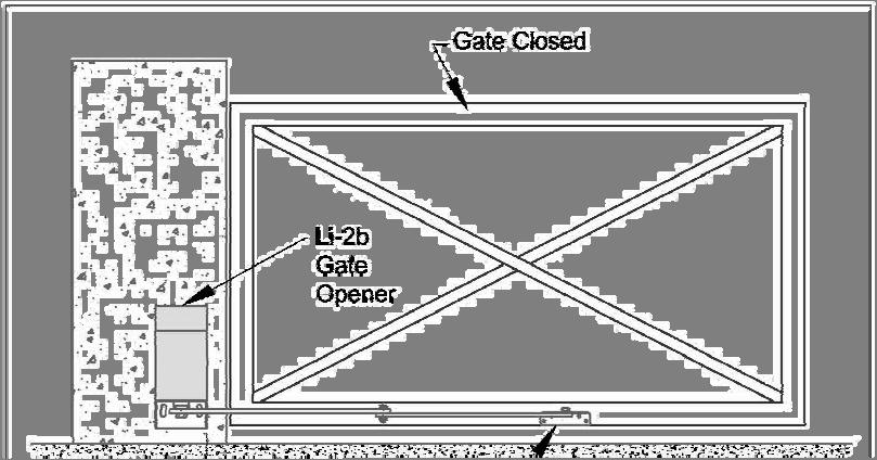
6 Installation Standard Installation A Standard Installation is one where the gate(s) open by swinging INWARDS towards the motor housing. The gate hinge should be no more than 200mm from the rear of the pier/post. Side room of 350mm is required to accommodate the swing of the arms. Refer to Pages 10 & 11 if there is restricted side room (See figure 1) Installation Procedure 1. Ensure that the gates swing freely and that all existing latches/pad-bolts/chains etc are disabled or removed from the gate and gate posts. 2. When using a 240-volt unit, The Master operator (the one containing the circuit board) should be fitted to the gatepost nearest the power supply. Remove the cover(s) from the operator to access the slotted fixing holes in the rear of the chassis. Bend the tabs out and bend them back against the rear of the chassis, in this position they act as a spacer allowing clearance for the cover(s). NOTE: Do not remove these tabs just bend them out and fold them to the back unless you are using the OPTIONAL mounting plate. 3. Position each unit on the gate-post{s} approximately 50mm from the edge of the pier/post. The vertical position is found by locating the gate bracket. The gate bracket is best placed where there is adequate fixing on the gate and movement of the arms is unrestricted (See Figure 2). The gate operator may now be bolted in place.


7
 (See")

.")


 5. The gate bracket should be positioned so the arms are ALMOST")

8 4. If you have a pair of gates then connect the slave to the Master Unit with 2 core Flex/Cable (Max load 8 Amp at 12 Volts) (See Figure 3). The LI-2B operators are set in the factory for a Standard Installation with the Master placed on the LEFT HAND SIDE (From the inside looking out). If the Master has to be located on the right then the motor wires need to be reversed. To accomplish this, locate the connection blocks for each motor on the Circuit Board. Swap the BROWN and BLUE wires for Motor 1 and Motor 2 (See Figure 3) 5. The gate bracket should be positioned so the arms are ALMOST in a straight line when the gates are closed (See figure 4). To check the location of the gate brackets, first disengage the Main arm from the drive shaft (using the spanner provided, unscrew the bolt until the arm swings freely) THEN CLAMP THE GATE BRACKET IN POSITION. Open and close the gate to ensure the gate bracket is appropriately located.


9 6. Connect Power (12 volt or 24 volt or solar) to the Primary operator and connect the battery 7. The Limit Switches may now be adjusted (See figure 5). Each of the Master and Slave operators has its own pair of cams, one to set the open position and one to set the closed position. Firstly mark the position of each cam as a reference. Loosen the screw holding the cams. Operate the LI-2B operator with the transmitter and note which cam controls opening and which cam operates the closing motion. (The cam lobe activates a Limit Switch to turn off the motor). Reposition each cam and operate the LI-2B again. Repeat until the gates open and close to the required positions. 8.


10 Side Mount Installation The LI-2B operator may be mounted sideways with the long side against the pier/post for extra flexibility. This feature is very useful for situations where (Refer to figure 6) The gate must swing further than 90 degrees The gate swings outwards The gate swings outward and it is positioned at least 400mm forward of the back of the pier/post Note: See section on out swing installation. Each LI-2B operator should be fitted to the pier/post with its output shaft close to the gate hinge. With this in mind the Standard Installation instructions may now be followed. Special covers are supplied to suit this type of installation.
.")
. 2.")


11 Restricted Side Room Installation This term is applied to the situation where the movement of the standard arms cannot be accommodated within the side room available. In most situations this problem can be overcome by cutting down the secondary arm. (The link joining the gate to the primary arm). This new length can be approximated by the following procedure. 1. Move the primary arm to a position suitable for the closed gate. Remembering that in the closed position the primary and secondary arms must stop short of a straight-line alignment (See Figure 7). 2. Mark a point on the gate suitable for the gate bracket. Holding the gate bracket in position, measure the distance between the hole centres on the gate bracket and primary arm. Move the primary arm to its maximum open position. Open the gate and measure the distance again. (See figure 8). If the length has changed then the gate bracket must be repositioned and the same process repeated until the dimensions remain the same for both positions. Be careful that the secondary arm does not conflict with the drive shaft of the primary arm. 3. Once the dimensions are consistent a new hole can be drilled in the secondary arm and the arm trimmed to suit. The gate bracket and secondary arm should now be fitted.
12 Out-Swing Installation In this type of installation the gate swings outward away from the LI-2B operator to the open position. Several factors must be considered to determine the most suitable arm length. These include The drive through width required The placement of the gate operator The location of the gate on the pier/post For assistance (if required) please provide a drawing (mud map) of your situation showing all possible measurements. Possible measurements include width between piers/posts, size of piers/posts, single or double gates, position of hinges on piers/posts etc. Note: The polarity of the motor connections may need to be reversed for out-swing operation. See overload section.
.")

 reach full travel on limit switches in OPEN and CLOSED")
 Red LED Close Position This JUMPER fits onto any two of three pins If fitted on pins 1 and two")
13 Settings Auto Close The operator control board is supplied with a JUMPER installed on a three-pin block. This allows the gate to automatically close after a specific period. This period is adjustable. (Refer to figure 9). Turn Auto Close delay dial (Trimpot) Anti-clockwise to increase the hold open time delay before gate closes automatically. Turn/dial trimpot clockwise to shorten the hold open time delay before gate closes automatically. Travel Time There is a Travel Timer and a yellow LED and trimpot dial located to the left of the Auto close Jumper. This should be set to approximately 5 to 10 seconds after full operation after gate(s) reach full travel on limit switches in OPEN and CLOSED position (See figure 10). Travel time can be adjusted by turning dial/trimpot Anti-clockwise to extend travel time and vice-versa. Green LED Open Position (Located above relay 4) Red LED Close Position This JUMPER fits onto any two of three pins If fitted on pins 1 and two the gate is set to close automatically. If fitted on pins two and three the gate will require a signal to close If there is no JUMPER or it is lost the gate will close automatically.
14 Multi-User Function This function is for when the LI-2B gate operator is installed for multi-users (e.g. flats, Apartments etc.) There is a Jumper installed on a three-pin block approximately in the middle of the main control board. If the Jumper is on pins one and two the operator WILL NOT allow the gate to close on a signal, it will continue to open position, time out then auto close. If the Jumper is on pins two and three (Normal) a signal e.g. from the remote control will reverse the direction of the operator. Overloads The overloads (See figure 9) are preset to maximum sensitivity, i.e. slight pressure will cause the operator to STOP if it is opening or STOP & OPEN if it is closing. Note: If these functions are reversed i.e. the gate STOPS when closing and STOPS and REVERSES when opening then the polarity of the motor connections MUST be reversed and the limit switch cams adjusted. There is ONE overload for each gate as indicated on the main circuit board. To reduce the sensitivity on the main circuit board turn the overload dials in the Anti-Clockwise direction. BE CAREFUL large reductions in sensitivity may allow the gate(s) to exert excessive pressure on people or vehicles trapped in the path of the gate(s). Anti-Clash Leaf Delay for Pairs of Gates To avoid jamming there is a time delay between the movements of each gate. This delay may be independently adjusted for the Opening sequence and the Closing sequence. Dial R24 changes the closing delay and R27 changed the opening delay. In situations where the master operator is on the right hand side looking out, the R24 sets the Opening delay and R27 sets the Closing delay. Turning the dials/trimpots Anti-Clockwise gives the minimum delay.


 must be connected to")
 are provided on the")
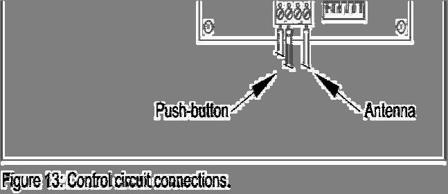
15 Push-Button, Key Pad etc. A variety of hard-wired input devices can be used to operate the LI-2B operator. Input should be in the form of a MOMENTARY CLOSED CIRCUIT. WARNING! Voltage must not be applied to these terminals. DAMAGE to the circuitry will result if voltage is applied. Devices that send a Voltage Pulse (As some intercoms do) must be connected to the circuit board through a relay. Electric Lock Connections for an electric lock/latch (EL) are provided on the circuit board. (See Figure 9) This connection block will supply 12 Volts to energise the lock at the beginning of the Opening and Closing cycles.
 will reverse to the open position.")

16 Photoelectric Safety Cell (240 volt & 12 volt operators only A photoelectric safety cell (PE) may be fitted to detect obstructions in the path of the gate(s). The PE will check for obstructions during the closing cycle only. If an obstruction is encountered the gate(s) will reverse to the open position. If the gate is set in the automatic close mode the gate(s) will remain open until the obstruction is cleared. Wires from the PE should be attached to the appropriate connection block. (See figure 9) Note: Extra power consumption will occur when using Photoelectric Cells so extra panel(s) and battery(s) will be required when gate(s) are operating on solar power only.
17 Solar Wiring Detail Step 1 Locate two way terminal connection block on top plate near motor. This will have Red (Positive) and black (Negative) wires. Connect solar panel direct to it. Red Black + - Brown or Red Blue or Black Solar Panel IMPORTANT As a connected solar panel delivers a charge, the solar panel must be covered or disconnected when any work or wiring is being done on the control board (other than when adjusting trimpots or limit switches) Step 2 Locate RED wire with spade terminal (Which will be disabled from Positive on Battery). Connect this wire and you are ready to set your limits. Negative Wire is already connected - + Red Wire to + Locate Positive Wire (RED) Connect RED wire to + on battery 7.2 Amp Hour SLA Batt Note: All LI-2B gate operator kits (Solar, 240 volt and 12 volt) are supplied complete with a 7.2 Amp hour battery. This battery should be checked regularly.
18 Trouble Shooting Poor range with the radio transmitter (Tx). Our standard transmitters are factory tested to 200 metres. 433Mhz Antenna is generally included to maximize signal to the radio receiver (Rx). Poor range may occur for several reasons. The first two things to check are: A. The Battery in the Tx B. Antenna installation and wiring Other causes is interference from other radio sources such as Electric fences Baby Monitors Other local transmitters Here the best solution is to remove the external source. If this is not possible the problem may sometimes be solved by using special frequency transmitters and a matching radio receiver (Rx). These are options that must be specifically ordered. Other faults may be due to incorrect settings. Refer to Settings section of this manual to ensure the settings are correct.
19 Specifications Dimensions Case: 245mm (H) x 140mm (W) x 335mm (D) Primary Arm: Pivot Centres 550mm Secondary Arm: Pivot Centres 570mm Weight Master Unit including battery Slave 21kg 17kg Remote Control Systems Arco can supply hand held transmitters and receiver boards. There are three models of hand transmitters available single, two and four button. The multi-button units allow individual operation of several devices (gates, doors etc.) from one hand transmitter. Where a system is already installed, on say the garage door, conversion kits can be fitted to allow operation of the door and gates from one multi-button transmitter. Power Requirements Standard.240 Volts 50Hz AC


20

21 0.5A Fuse Auto Reverse Motor 1 & 2 c/wise = less force Travel Time LED Auto Close Anti-c/wise to increase hold open time Battery Negative Positive DC In Negative Positive 10A Fuse Motor 1 Open Close Motor 2 Open Close Electric Lock Negative Positive Travel Time c/wise = minimum Travel Time Three Pin Block Jumper on 1 & 2 = Auto Close Jumper on 2 & 3 = Manual Close Close Delay Open Delay c/wise = Maximum Delay Photoelectric Safety Push Button Open LED Green Close LED Red

22 Arco Pty. Ltd. reserves the right to make changes without notice so discrepancies may occur due to product upgrades. Arco Pty. Ltd Macbeth Street Braeside, Victoria, 3195 Phone:
Letron Auto Gates (Australia) Pty. Ltd. User s Installation Manual
 Pty. Ltd. User s Installation Manual") Letron Auto Gates (Australia) Pty. Ltd. User s Installation Manual Sliding Gate Motor AUTOMATIC OBSTRUCT PHOTO ELECTRIC BEAM ROLLING CODE SYSTEM AUTO CLOSE DOOR SOLAR COMPATIBLE ( DC ONLY ) Model SL810
Letron Auto Gates (Australia) Pty. Ltd. User s Installation Manual Sliding Gate Motor AUTOMATIC OBSTRUCT PHOTO ELECTRIC BEAM ROLLING CODE SYSTEM AUTO CLOSE DOOR SOLAR COMPATIBLE ( DC ONLY ) Model SL810
F ERNI K I T THE FERNI-S KIT CONSISTS OF:
 CAME UNITED KINGDOM LTD ORCHARD PARK INDUSTRIAL ESTATE TOWN STREET, SANDIACRE, NOTTINGHAM, NG10 5BP TEL: 0115 921 0430 FAX: 0115 921 0431 INTERNET - www.cameuk.com E-MAIL - enquiries@cameuk.com TECHNICAL
IMPORTANT SAFETY RECOMMENDATIONS
 801-001-01 C IMPORTANT SAFETY RECOMMENDATIONS FAILURE TO COMPLY WITH THE FOLLOWING SAFETY RECOMMENDATIONS MAY RESULT IN SERIOUS PERSONAL INJURY AND/OR PROPERTY DAMAGE. 1. For ADDITIONAL SAFETY we STRONGLY
Gate & Door Controller with LCD and Intelligent Technology
 2nd Edition Gate & Door Controller with LCD and Intelligent Technology 24Sv1 and 12Sv1 Motor Controllers Setup and Technical information for single motor controller for gates & doors Includes latest Intelligent
LIFTMASTER MAGIC BUTTON FS10 & LPK5 FAST SLIDER
 R MAGIC BUTTON FS0 & LPK5 FAST SLIDER OPERATORS MANUAL FEATURES High speed -800mm/second Corrosion resistant - Hot dip galvanised base with stainless steel cover Speed flexibility - Slow start / slow stop
Installing the gate post bracket with the cardboard arm template
 ......... Installing the gate post bracket with the cardboard arm template... Installing gate posts brackets and arms for Push-to-Open or Pull-to-Open gates... Connection of Power Source 240Vac or Solar...
Instruction Manual for the. E-SL 450 Series
 Instruction Manual for the E-SL 450 Series Estate Slide Summary of Functions The Estate Slide is only to be used for vehicular Slide gates in a Class I setting. Class I: A vehicular gate opener (or system)
ELSEMA Single / Double Gate Controller, with Battery Charger, for 12V / 24V Motor, Enclosed, GATCOxxxCH
 GATCO12SCH, GATCO24SCH, GATCO12DCH, GATCO24DCH Single / Double Gate Controller, with Battery Charger, for 12V / 24V Motor Features 4 Versions: GATCO12SCH 12V Single motor GATCO24SCH 24V Single motor GATCO12DCH
Installation and Set Up Instructions
 Model FG 5-7 / SW 5-7 / DSW 5-7 Swing Gate Motor Kit Solar powered and 12V Low Voltage Installation and Set Up Instructions Unit 27 / 49 Corporate Boulevard Bayswater Vic 3153 Phone 1800 111 930 Email
AgriWheel Single Gate Kit Low Voltage & Solar. Installation & Operating Instructions
 AgriWheel Single Gate Kit Low Voltage & Solar Installation & Operating Instructions Thank you for purchasing you AgriWheel system. Please remove the lids from both the machine and control box and remove
APOLLO Gate Operators, Inc.
 APOLLO Gate Operators, Inc. Model 3500ETL/3600ETL Commercial Swing Gate Operator INSTALLATION MANUAL 01/08 CONTENTS IMPORTANT SAFETY INSTRUCTIONS. 3 Applications... 4 Pre-Installation Checklist... 5 Parts
SWING GATE OPENERS 24V DC GEAR MOTOR
 SWING GATE OPENERS 24V DC GEAR MOTOR FOR RESIDENTIAL USER MANUAL Flashing Light Push Button Control box Gate 2 Gate 1 Index Warnings 2 5. Technical Characteristics 21 1. Product Description and Applications
Installing the gate post bracket with the cardboard arm template
 ......... Installing the gate post bracket with the cardboard arm template... Installing gate posts brackets and arms for Push-to-Open or Pull-to-Open gates... Connection of Power Source 240Vac or Solar...
Saimatic Aster Gate Operator, Automation System Manual. 110V or 220V
 Saimatic Aster Gate Operator, Automation System Manual 110V or 220V 1 WARNINGS AND PRECAUTIONS Read the instructions carefully before installing the gate automation system. Keep these instructions for
INSTALLATION M ANUAL
 INSTALLATION MANUAL Table of Contents UL Listings Installing the Warning Sign / Precautions Methods of Installation / Compact Installation Mounting the Secondary Entrapment / Welding Gate Arn Mounting
AUTOMATIC CONTROL ROLLING DOOR OPENER
 AUTOMATIC CONTROL ROLLING DOOR OPENER INSTALLATION INSTRUCTION AUTOMATIC OBSTRUCT PHOTOELECTRIC BEAM ROLLING CODE SYSTEM AUTO CLOSE DOOR ANTI-THEFT SYSTEM INSTALLATION INSTRUCTION AND RDO OWNERS MANUAL
TMT Boxer 24v slider motor installation notes from EasyGate
 TMT Boxer 24v slider motor installation notes from EasyGate Install Physical Gate Stops Physical Gate Stops MUST be installed at each end of your gate. If the Limit Switch on the boxer motor fails to stop
SWING GATE OPENERS 24V DC GEAR MOTOR
 SWING GATE OPENERS 24V DC GEAR MOTOR FOR RESIDENTIAL USER MANUAL Flashing Light Push Button Control box Gate 2 Gate 1 Index 1. Warnings 2 4. Technical Characteristics 16 2. Product Description 2.1 Applications
PW320/PW330 USER MANUAL SWING GATE OPENERS 24V DC GEAR MOTOR FOR RESIDENTIAL. Flashing Light. Push Button. Control box. Gate 2.
 PW320/PW330 USER MANUAL SWING GATE OPENERS 24V DC GEAR MOTOR FOR RESIDENTIAL Flashing Light Push Button Control box Gate 2 Gate 1 Declaration of Conformity Applicant: Powertech Electronics Inc. Manufacturer:
ELSEMA Single / Double Gate Controller, for 12V / 24V Motor, GATCO12S, GATCO24S, GATCO12D, GATCO24D
 GATCO12S, GATCO24S, GATCO12D, GATCO24D Single / Double Gate Controller, for 12V / 24V Motor Features 4 Versions: 12V / 24V Single / Double Motor Application Control an automatic door or Gate GATCO12S 12V
PW150/PW200 USER MANUAL SWING GATE OPENERS 24V DC GEAR MOTOR
 PW150/PW200 USER MANUAL SWING GATE OPENERS 24V DC GEAR MOTOR FOR RESIDENTIAL Flashing Light Push Button Control box Declaration of Conformity Applicant: Powertech Electronics Inc. Manufacturer: Timotion
INSTALLATION & OWNERS MANUAL. PowerGlide. PowerGlide
 RR INSTALLATION & OWNERS MANUAL PowerGlide Sectional Door Operator PowerGlide Sectional Door Operator N 13655 WARNING MOTORIZED SOLUTIONS www.acdcms.com.au AUSTRALIA 240V WARNING: It is crucial that these
GLM SERIES CONTROL Users Manual Rev:
 GLM SERIES CONTROL Users Manual Rev: 808062 Connecting Power Page 2 Motor Terminal Wiring Diagrams Page 3 Getting Started / Setup Page 4 1. Obstruction Detection Devices Page 4 2. Checking Power and Direction
TEL: G&C Electronics CC E. T.
 TEL: +27 21 448 6774 G&C Electronics CC FAX: +27 21 447 7794 E. T. CK 89/31531/23 E-mail : etsystems@icon.co.za Internet: www.et.co.za 15 Nelson Road P.O. Box 34524 Observatory Groote Schuur Cape Town
Model 2300JL Installation Guide
 Model 2300JL Installation Guide POWER ACCESS CORPORATION 4 HERSHEY DRIVE, DOCK 4 ANSONIA, CT 06401 800-344-0088 WEBSITE: www.power-access.com EMAIL: salesinfo@power-access.com 1 STANDARD PARTS MODEL 2300JL
Model 2300DL Installation Guide
 Model 2300DL Installation Guide POWER ACCESS CORPORATION 4 HERSHEY DRIVE, DOCK 4 ANSONIA, CT 06401 800-344-0088 WEBSITE: www.power-access.com EMAIL: salesinfo@power-access.com 1 STANDARD PARTS MODEL 2300DL
GENERAL SAFETY... 3 PARTS LIST...
 Rev 17a 1 GENERAL SAFETY... 3 PARTS LIST... 4 GTR100... 4 GTR058... 5 TECHNICAL SPECIFICATIONS... 6 FEATURES:... 6 QUICK INSTALLATION GUIDE... 7 GATE ARM INSTALLATION... 8 BEFORE YOU START... 8 INSTALLATION
Plasma Display Electric Pop-Up Lift (PUL)
") I N S T R U C T I O N M A N U A L Plasma Display Electric Pop-Up Lift (PUL) Your is designed for installation in furniture or cabinets. Display mounting is made easy using the Q-latch mounting system and
I N S T R U C T I O N M A N U A L Plasma Display Electric Pop-Up Lift (PUL) Your is designed for installation in furniture or cabinets. Display mounting is made easy using the Q-latch mounting system and
Model 1550 Single Swing Gate Model 1650 Dual Swing Gate
 Gate Operators, Inc. Model 1550 Single Swing Gate Model 1650 Dual Swing Gate Swing Gate Operator CONTENTS Safety Precautions... 2 Applications... 3 Pre-Installation Checklist... 4 Parts Identification...
INSTALLATION AND OWNERS MANUAL
 SLIDE GATE OPERATORS: COMPACT 300 COMPACT 500 SOLO CONDO CONDO AC/DC SWING GATE OPERATORS: DURASWING GARAGE DOOR OPERATORS: LAZER SECTIONAL LAZER ROLL UP LAZER VERTICAL ROLL UP LAZER TIP UP PROUD MANUFACTURERS
The House of Gate Automation
 OPTIONAL EXTRA'S SOFT START / SOFT START This is provided as an optional extra and must be requested to fit to a new or old system. It provides an adjustable slow start and slow stop to prevent slambing
HA PRO INSTALLERʼS MANUAL. HA-008 v3. User s/installer s Manual
 HA-008 v3 HA - 280 PRO User s/installer s Manual INSTALLERʼS MANUAL Manufacturer: COMMERCIAL ELECTRONICS 264 HAYDONS ROAD, WIMBLEDON, LONDON SW19 8TT. UK TEL: +44 020 8404 7105 FAX: +44 020 8404 7104 http://www.hawkcaralarm.com
DTS SECURITY P.O.BOX 3399 EDENVALE 1610 Base plate-mounting instructions TELEPHONE
 DTS ECO 500 SLIDING GATE MOTOR INSTALLATION MANUAL DTS SECURITY P.O.BOX 3399 EDENVALE 1610 Base plate-mounting instructions TELEPHONE 086 1000 387 Spartan +2711 392 5540 (H/O) Pretoria +2712 361 5528 Alberton
IMPORTANT: Before you install the automatic gate lock be sure your gate is level, moves freely on hinges, and is free from binding and/or dragging.
 Before You Start... IMPORTANT: Before you install the automatic gate lock be sure your gate is level, moves freely on hinges, and is free from binding and/or dragging. For the GTO Automatic Gate Lock work
Installation and Set Up Instructions
 SL 2000 DC2 SLIDING GATE MOTOR KIT Solar Powered and 12V Low Voltage Installation and Set Up Instructions Unit 27 / 49 Corporate Boulevard Bayswater Vic 3153 Phone 1800 111 930 Email info@gforceautogates.com.au
Instruction Manual MB4 Rolling garage door opener
 Instruction Manual MB4 Rolling garage door opener INSTALLATION INSTRUCTIONS OWNERS COPY 1 WARNING: It is vital for the safety of persons to follow all instructions. Failure to comply with the installation
R3 Roller Garage Door Opener
 R3 Roller Garage Door Opener INSTALLATION INSTRUCTIONS OWNERS COPY 1 WARNING: It is vital for the safety of persons to follow all instructions. Failure to comply with the installation instructions and
Single or Double 240VAC motor control for domestic and industrial gates and doors.
 COBO30 Double 240V Motor Drive Controller Features For 240Volt Motors Auto Closing Open Only Security Closing and Extended Lock Pulse (user selectable) Travel Timer Push Button Input Photo Cell Input Option
SKC400U SLIDING GATE OPENER OWNER S MANUAL
 SKC400U SLIDING GATE OPENER OWNER S MANUAL IMPORTANT SAFTEY INFORMATION Installing the SKC400U Gate Opener requires wiring of standard 110V electrical lines. This should only be performed by a trained
PHOENIX Amp Brushless Sensorless Speed Control. 1.0 Features of the Phoenix-25 : 2.3 Connecting the Motor. 2.4 Reversing Rotation
 1.0 Features of the Phoenix-25 : Extremely Low Resistance (.013 ohms) High rate (7 KHz) switching (PWM) Up to 25 Amps continuous current with proper air flow, 35 amps surge Five to eight cells with four
CB-9 CONTROL BOARD INSTRUCTION MANUAL
 CB-9 CONTROL BOARD INSTRUCTION MANUAL AUGUST 95 The CB-9 control board is designed to automate 1 or 2 A.T.A swing gate or sliding gate drive units. This instruction manual gives detailed instructions on
MODEL JH JACKSHAFT INDUSTRIAL DOOR OPERATOR INSTALLATION MANUAL. OPERATOR SPECIALTY COMPANY, INC. P.O. Box 128 Casnovia, MI 49318
 MODEL JH JACKSHAFT INDUSTRIAL DOOR OPERATOR INSTALLATION MANUAL OPERATOR SPECIALTY COMPANY, INC. P.O. Box 128 Casnovia, MI 49318 OSCO requires the use of a reversing edge or photoelectric control for pedestrian
FROG KIT. Installation Instructions for a Pair of gates... TECHNICAL HELPLINE THE FROG-P KIT CONSISTS OF:
 CAME UNITED KINGDOM LTD UNIT 3 ORCHARD PARK INDUSTRIAL ESTATE, TOWN STREET, SANDIACRE, NOTTINGHAM NG10 5BP TEL: 0115 921 0430 FAX: 0115 921 0431 TECHNICAL HELPLINE 0115 921 0430 INTERNET - www.cameuk.com
42 Series Step. Owner's Manual #842A. Equipped with a Permanent Magnet Motor. Table of Contents
 Owner's Manual #842A 10/05 Kwikee #1422258, Rev. 0A ED 42 Series Step Equipped with a Permanent Magnet Motor D IS C O N TI N U For steps with Control Unit 909510000 and steps without Control Units Table
Installation and Set Up Instructions
 SL SLIDING GATE MOTOR KIT Solar Powered and 12V Low Voltage Installation and Set Up Instructions Unit 27 / 49 Corporate Boulevard Bayswater Vic 3153 Phone 1800 111 930 Email info@gforceautogates.com.au
CMD-4000 SERIES REV. A 4+ FUNCTION REMOTE CONTROL DOOR LATCH OPENER SYSTEM INTRODUCTION
 CMD-4000 SERIES REV. A 4+ FUNCTION REMOTE CONTROL DOOR LATCH OPENER SYSTEM INTRODUCTION Thank you for purchasing the CMD-4000 series Remote Control Door Latch Opener System from Dakota Digital, Inc. This,
R3R5 quick setup guide ROTARY SWING GATE OPERATOR
 R3R5 quick setup guide TM TM ROTARY SWING GATE OPERATOR 1 REQUIRED TOOLS & EQUIPMENT Check that you have all the tools required. (IM page 1) 3 SITE CONSIDERATIONS Check for the safety and suitability of
WWWAUTO-ROLLER.CO.ZA INSTALLATION MANUAL AUTO- ROLLER
 WWWAUTO-ROLLER.CO.ZA INSTALLATION MANUAL AUTO- ROLLER Notice. Please read these instructions carefully before installing the Rolling Door motor 1. The motor must be installed and operated by a professional.
C15C C15C. Page 1 of 20
 2 x Lid Front Hinge 1135 8 x M8 Bolt 8 x M8 Washer (3mm Thick) 4 x M6 Large washers 4 x M6 Spring washers 4 x M6 x 40mm Bolts 6 x M6 20mm Bolts 6 x M6 Washers 20 x Screws 2 x Lid mount gas strut bracket
MIC210 Electric Farm Conversion Instructions
 MIC210 Electric Farm Conversion Instructions Note: Apply the supplied Dielectric Lubricant to all wire connections when each wire is hooked up. The Dielectric Lubricant will help to prevent corrosion.
Acdc slimglide roller door operator
 Acdc slimglide roller door operator Owners manual ACDC SlideGlide ROLLER DOOR OPERATOR WARNING It is vital for the safety of persons to follow all instructions. Failure to comply with the installation
Electronic Dynamo Regulator INSTRUCTION MANUAL. COPYRIGHT 2014 CLOVER SYSTEMS All Rights Reserved
 DRM TM DRM-HP TM Electronic Dynamo Regulator INSTRUCTION MANUAL COPYRIGHT 2014 CLOVER SYSTEMS All Rights Reserved INTRODUCTION The Clover Systems DRM is a state-of-the art all-electronic voltage and current
APOLLO Gate Operators, Inc.
 APOLLO Gate Operators, Inc. Model BA12 12 VOLT DC BARRIER ARM OPERATOR INSTALLATION MANUAL 0707 CONTENTS IMPORTANT SAFETY INSTRUCTIONS... 3 Applications... 4 Pre-Installation Checklist... 5 Operator Installation...
HYPPOETL HYPPO DUALETL 12 VOLT DC Swing Gate Operator
 HYPPOETL HYPPO DUALETL 12 VOLT DC Swing Gate Operator Manufactured by NICE SpA INSTALLATION MANUAL 08/10 CONTENTS IMPORTANT SAFETY INSTRUCTIONS... 3 Applications...... 4 Pre-Installation Checklist... 5
APOLLO Gate Operators, Inc.
 APOLLO Gate Operators, Inc. Model 7200ETL Post Mounted Residential & Heavy Duty Commercial Slide Gate Operator INSTALLATION MANUAL 04/11 CONTENTS IMPORTANT SAFETY INSTRUCTIONS... 3 Applications... 4 Pre-Installation
Sectional And Tilting Door Opener
 Sectional And Tilting Door Opener Installation Instructions and User Guide FS 600 FS 1000 FS 1200 600N 1000N 1200N FS 600-Speed FS 1000-Speed 600N 1000N S/N WARNING Please read the manual carefully before
MODEL MSW Medium Duty Swing Gate Operator
 INSTALLATION AND OWNER S MANUAL MODEL MSW Medium Duty Swing Gate Operator UL 325 and UL 991 Listed 22-1/4 16-1/2 19-1/2 16 20'' LENGTH X 14-3/4'' WIDTH 2 O.D. PIPE (BY OTHERS) Serial #: Date Installed:
D Vers. 03 ELECTROMECHANICAL AUTOMATION FOR SWING GATES
 E5 D811007 15-09-99 Vers. 03 ELECTROMECHANICAL AUTOMATION FOR SWING GATES 122 This product complies with recognised technical standards and safety regulations. We declare that this product is in conformity
Electronic Dynamo Regulator INSTRUCTION MANUAL. COPYRIGHT 2014 CLOVER SYSTEMS All Rights Reserved
 DRM TM DRM-HP TM Electronic Dynamo Regulator INSTRUCTION MANUAL COPYRIGHT 2014 CLOVER SYSTEMS All Rights Reserved INTRODUCTION The Clover Systems DRM is a state-of-the art all-electronic voltage and current
Installation Guide Rollerdor RD55 Econ Roller Garage Door
 Installation Guide Rollerdor RD55 Econ Roller Garage Door 1 Finished door Rollerdor RD55 Econ Roller Garage Door CHECKLIST & COMPONENTS EQUIPMENT REQUIRED 2 x Step ladders or hop ups Spirit level Tape
Tech Note Truck 14 & 15.5 Twin Plate Cast Iron Type Installation Guidelines
 1. (14 & 15.5 ) Check condition of the flywheel. Grind to resurface or replace flywheel. Surface MUST BE machined or premature clutch failure can occur. Flywheel depth must be 2.938 (74.62mm) for 14 (350mm)
access
 184 Table of Contents Access Garage door Motors Dexxo Pro 800 RTS... 188 Dexxo Pro 1000 RTS... 189 Dexxo Optimo RTS... 190 Receiver Axroll NS... 191 Freeroll ESE RTS, RTS receiver for roller garage doors...
Porte 150 Users Manual Swing Gate Opener 24V DC
 Porte 150 Users Manual Swing Gate Opener 24V DC for residential use only Signal Light Push-button Control Box 14 Contents 1. Important Safety Information 2. Product Description and Application 2.1 Application
Operators Guide: RoboSign Stop/Go Traffic Control System
 Operators Guide: RoboSign Stop/Go Traffic Control System RoboSign Remote controlled Stop/Go temporary traffic control system Operators Guide NZTA Conditions - Automated Stop/Go Traffic Control System NZTA
SPACESAVER EC-300 A ELECTRICS
 INSTALLATION INSTRUCTIONS SPACESAVER EC-300 A ELECTRICS SECTION I TOP MOUNTED ELECTRICS SECTION II FACE PANEL MOUNTED ELECTRICS SECTION III ZFS INSTALLATION INSTRUCTIONS This symbol indicates a connection
PHOENIX Features of the Phoenix-25 : 2.3 Connecting the Motor. 2.4 Reversing Rotation. 2.5 Connecting the Receiver
 Warning! High power motor systems can be very dangerous! High currents can heat wires and batteries, causing fires and burning skin. Follow the wiring directions carefully! Model aircraft equipped with
PowerMaster MODEL MBG. Installation Manual U L R UL 325 AND UL 991 LISTED MEDIUM DUTY BARRIER GATE OPERATOR TABLE OF CONTENTS
 PowerMaster TABLE OF CONTENTS MODEL MBG MEDIUM DUTY BARRIER GATE OPERATOR Important Safety Information...... 3 System Designer Safety Instructions.......4 Installer Safety Instructions....... 5 Installation
contents OPERATOR Maintenance SHAFT-120 Installation and Operating Manual DoorHan, 2012
 OPERATOR contents General Information Safety instructions Operator unit operator Installation Electrical Connections adjustment of extreme positions operator programming Release operation Maintenance Trouble
PHOENIX Features of the Phoenix-10 : 2.3 Connecting the Motor. 2.4 Reversing Rotation. 2.5 Connecting the Receiver
 Warning! High power motor systems can be very dangerous! High currents can heat wires and batteries, causing fires and burning skin. Follow the wiring directions carefully! Model aircraft equipped with
Automatic Gate Lock Installation Manual
 IMPORTANT: Before you install the automatic gate lock be sure your gate is level, moves freely on its hinges, and does not bind or drag against the ground. Automatic Gate Lock Installation Manual PLEASE
Gate Operators, Inc. Model 7100UL Residential & Medium Duty Commercial Slide Gate Operator INSTALLATION MANUAL
 Gate Operators, Inc. Model 7100UL Residential & Medium Duty Commercial Slide Gate Operator INSTALLATION MANUAL 10-04-00 CONTENTS Safety Precautions... 2 Applications... 3 Pre-Installation Checklist...
REMOTE CARAVAN MOVER Installation guide and user information. e-go /10/01/rev 3
 REMOTE CARAVAN MOVER Installation guide and user information Contents 1 1 Introduction 3 Parts List 4 Safety Guidelines 4 Technical Specifications 5 Fitting Guidelines (chassis adapters etc.) 6 Fitting
Instruction Manual MINI IRRIGATION CONTROLLER.
 MINI IRRIGATION CONTROLLER www.krain.com Station Models - Available in 4 OR 6 stations. OUTdoor MODEL - Supplied with 120VAC x 24VAC inbuilt transformer. Optional LEAD with Plug. Instruction Manual Table
GARAGE DOOR OPERATOR USER S MANUAL
 GARAGE DOOR OPERATOR USER S MANUAL - DOMESTIC USE CIL-CD800S Chain) CIL-BD800S Belt GARAGE DOOR OPENER OWNER S MANUAL - DOMESTIC USE CIL-CD800S CD800S(Chain Chain) CIL-BD800S BD800S(Belt Belt) 1 Features
IQ Gate Systems. IQ-500 Installation And Instruction Manual UL 325 and UL 991 Compliant.
 IQ Gate Systems IQ-500 Installation And Instruction Manual www.iqgatesystems.com 1-801-455-7961 UL 325 and UL 991 Compliant Revision B IQ Gate Systems: IQ-500 Installation IQ-500 Capacities: Swing gates
Reproduction or other use of this Manual, without the express written consent of Vulcan, is prohibited.
 SERVICE MANUAL ELECTRIC BRAISING PANS (30 & 40 GALLON) VE30 VE40 ML-126849 ML-126850 VE40 SHOWN - NOTICE - This Manual is prepared for the use of trained Vulcan Service Technicians and should not be used
TELEPHONE TECHNICAL SERVICES DS5 USER GUIDE
 TELEPHONE TECHNICAL SERVICES DS5 USER GUIDE Manufactured in Australia for Telephone Technical Services PO BOX 675 SPRINGWOOD QLD 4127 PRODUCT DESCRIPTION This User Guide describes the installation and
BX88175 Installation Instructions ToadStop II Vacuum Brake System
 BX88175 Installation Instructions ToadStop II Vacuum Brake System Serial No. Customer supplied tools & supplies Utility knife, 12VDC tester, drill & bits: (1/8", 1/4", 5/8 ), ¼ socket drive bit, punch,
CHECKLIST & COMPONENTS
 Eclipse Compact www.rollershuttercompany.com Tel 0800 6444121 55mm Roller Garage Doors CHECKLIST & COMPONENTS EQUIPMENT REQUIRED 2 x Step ladders or hop ups Spirit level Tape measure Power drill 10mm A/F
Reverse Polarity MANUAL. Surechlor S3500
 Reverse Polarity MANUAL Surechlor S00 Surechlor S00 MANUAL Contents Installation Cell Power pack Off Peak Installation Connecting the Pool Pump Installation Layout Operation Chlorine Control LED Chlorine
8. Do not install this product on the exterior of buildings. 9. Do not use as a doorstop. This will void warranty. Installation Instructions
 INSTALLATION 8310-IQ/8320-IQ IntelliMag Electromagnetic Locks Pre-Installation Instructions 1. This product must be installed according to all applicable building and life safety codes. 2. Due to the variety
Installer Instructions
 (400mm stroke length) Plus For dimensions of the 300mm model please contact us directly Installer Instructions 1 Page Table of contents Category Introduction 3 Safety obligations and general warnings 4
Linear Actuator Swing Gate Operator Installation Manual Model # LA405-24
 Linear Actuator Swing Gate Operator Installation Manual Model # LA405-24 2 Contents Contents Product Information and Specs. 3 Mechanical 3 Electrical, Line Connections 3 Electrical, Control Connections
Sprayer Control. Manual for SprayLink Cable Installations. Tank. Jet Agitator. Agitator Valve. Diaphragm Pump. Pressure Transducer.
 Sprayer Control Plumbing & Installation Manual for SprayLink Cable Installations Tank Jet Tank Shut-Off Diaphragm Pump Electric Ball s Transducer Strainer Relief Regulating Copyrights 2012 TeeJet Technologies.
INSTALLATION AND INSTRUCTION MANUAL MODELS: PRO-T, PRO-TB
 INSTALLATION AND INSTRUCTION MANUAL MODELS: PRO-T, PRO-TB AUG, 2010 2 TABLE OF CONTENTS PAGE: VERIFICATION OF OPERATOR AND HARDWARE 3 SPECIFICATIONS 4 SAFETY INSTRUCTIONS 5 INSTALLATION 6 ELECTRICAL CONNECTIONS
MASTER SALT SAND SPREADER WIRELESS CONTROL MANUAL
 MASTER SALT SAND SPREADER WIRELESS CONTROL MANUAL This manual covers 1. Gas spreader wireless controllers (Standard) 2. Gas spreader wireless controllers (Plus) 3. 600DC single motor spreader wireless
SHIFNOID WIRING DIAGRAM
 SHIFNOID WIRING DIAGRAM FOR a HURST QUARTER STICK with a SN5055H THREE SPEED SOLENOID KIT IF YOUR RPM SWITCH OR TIMER SUPPLIES "NORMALLY OPEN GROUND" (SHIFNOID OR MSD) USE THIS DIAGRAM 86 NOT USED 87a
HIGH SPEED SLIDING GATE OPENER
 HIGH SPEED SLIDING GATE OPENER Model: is1200 + Elsema s Eclipse Control Card with GDS Operator USER MANUAL CONTENTS Section No: Page No: 1 Safety Precautions 3 2 Wiring Requirements 4 3 Installation details
Automatic Battery Charger Switching mode with Micro-controlled Input: Vac / Output: 12Volt DC
 Automatic Battery Charger Switching mode with Micro-controlled Input:220-260Vac / Output: 12Volt DC User s Manual and Important Safety Information Model: OC-SW121080 / OC-SW121160 / OC-SW121210 FEATURES
RE Generation II Troubleshooting Guide Section I Preliminary Information and Evaluation
 DODGE ENGINEERING & CONTROLS, INC. 196 Riverneck Road Chelmsford, MA 01824 PHONE (978) 244-1200 FAX (978) 244-1422 TOLL FREE (877) 334-2875 RE Generation II Troubleshooting Guide Section I Preliminary
DODGE RAM 2500
 81234007 2014-2015 DODGE RAM 2500 Congratulations - your new LevelTow Helper Springs are quality products capable of improving the handling and comfort of your vehicle. As with all products, proper installation
Operators, Inc. Model 1550ETL Single Swing Gate Operator Model 1650ETL Dual Swing Gate Operator INSTALLATION MANUAL 04/07
 APOLLO Gate Operators, Inc. Model 1550ETL Single Swing Gate Operator Model 1650ETL Dual Swing Gate Operator INSTALLATION MANUAL 04/07 CONTENTS IMPORTANT SAFETY INSTRUCTIONS... 3 Applications... 4 Pre-Installation
The Right Angle of the Latch to the Snare. Adjusting the Latch relative to the Snare
 Page 1 Applies to product version - 2018 File: Installation-18 Sept Before you start here you should have looked at the Before You Install details. This is designed to help you with the vast range of trailers,
MODEL D-WBG Wishbone Arm Barrier Gate Operator
 INSTALLATION AND OWNER S MANUAL MODEL D-WBG Wishbone Arm Barrier Gate Operator UL 325 and UL 991 Listed WITH NITRO BOARD (SEE SUPPLEMENTAL MANUAL) Serial #: Date Installed: Your Dealer: READ THIS MANUAL
2904 Power Supply Installation Instructions I-EA00041
 FEATURES Controls an opening with electrified locking device and automatic door operator Separate inputs for activation switch on entry and exit sides of opening Separate 24 VDC outputs for fail safe and
12V DC MOTORISED OPENER FOR SWING GATES Section Table of Contents Page
 12V DC MOTORISED OPENER FOR SWING GATES Section Table of Contents Page 1 Introduction 2 2 Warnings 4 3 Technical Specifications 5 4 Positioning 6 5 Wiring Diagram 7 6 Standard Installation Kit 8 7 Installation
ELSEMA 240VAC Slider Control Board, SLD
 SLD Slider Control Board ELSEMA Features For Single 240VAC Motor Built-in transformer, auto close, open only, security close & special security close Application Control an automatic door or gate with
BOLT-ON AND WELD-ON FLUSH FLOOR SLIDEOUT SYSTEMS OPERATION AND SERVICE MANUAL
 BOLT-ON AND WELD-ON FLUSH FLOOR SLIDEOUT SYSTEMS OPERATION AND SERVICE MANUAL TABLE OF CONTENTS SYSTEM...... Warning........ Description...... Prior to Operation OPERATION... Main Components... Mechanical...
PRIMUS IMPORTANT. User Manual and Product Specifications. Portable Solar Panel Kit 80 watt. Read instructions before operation. Part No.
 PRIMUS Portable Solar Panel Kit 80 watt Part No. 522123 User Manual and Product Specifications IMPORTANT Read instructions before operation. Getting to know your Portable Solar Panel Kit Identification
User manual. e-gate SLD-24V
 User manual FOR e-gate SLD-24V 24V Sliding Gate Operators Contents how to use your automatic gate operator...... 1 how the controls work.................. 2 how to manually release the gate...........