APOLLO Gate Operators, Inc.
|
|
|
- Nicholas Small
- 5 years ago
- Views:
Transcription


1 APOLLO Gate Operators, Inc. Model 3500ETL/3600ETL Commercial Swing Gate Operator INSTALLATION MANUAL 01/08
2 CONTENTS IMPORTANT SAFETY INSTRUCTIONS. 3 Applications... 4 Pre-Installation Checklist... 5 Parts Identification... 6 Post Location Guide.. 7 Operator Installation EMERGENCY MANUAL OPERATION 13 Programming Current Sensing /836 Control Board Description Siren Installation.. 20 Radio Receiver Options Troubleshooting guide Warranty
3 IMPORTANT SAFETY INSTRUCTIONS WARNING - To reduce the risk of injury or death: READ AND FOLLOW ALL INSTRUCTIONS. Installation should be performed by a professional installer. Required welding should be performed by a qualified welder. Should electricity be required, use a certified electrician only. Any device that requires 120 Volts AC should be U.L. approved. Review with the owner all safety concerns including: Do not operate the gate unless area around gate is in full view. Never let children operate or play with gate controls. Keep the remote control away from children. Always keep people and objects away from the gate. NO ONE SHOULD CROSS THE PATH OF THE MOVING GATE. Periodically test the obstruction sensitivity to assure safe and proper operation. Do not test sensitivity by standing between the gate and the hinge or stop post. The CAUTION AUTOMATIC GATE signs should be clearly visible from both sides of the gate. Always insure that the gate has closed securely before leaving area. Arrange with local fire and law enforcement for emergency access. Use the emergency release only when the gate is not moving. A secondary entrapment device such as loop detectors, edge switches, and beam detectors are highly recommended and required to meet the UL325 standard. Install control devices such as keypads far enough away (5 feet or further) from any moving parts of the operator and gate to prevent possible injury. Do not install control box where the gate can come in contact with person using the push button on side of control box. Always disconnect the battery or power source when making adjustments or repairs to any part of the gate or operator. All rollers should be covered to prevent injury. KEEP GATES PROPERLY MAINTAINED. Read the owner s manual. Have a qualified service person make repairs to gate hardware. The entrance is for vehicles only. Pedestrians must use separate entrance. Test the gate operator monthly. The gate MUST reverse on contact with a rigid object or stop when an object activates the non contact sensors. After adjusting the force or limit of travel, retest the gate operator. Failure to adjust and retest the gate operator properly can increase the risk of injury or death. SAVE THESE INSTRUCTIONS. 3
4 APPLICATIONS The Model 3500/3600 Swing Gate Operator is designed for residential and commercial applications. The 3500/3600 is listed with ETL and complies with the UL 325 standard. The 3500/3600 will handle swing gates up to 20 feet in length and 1,000 pounds each. A professional fence or gate dealer is recommended to assure proper installation. The Model 3500/3600 operator is 12 Volt DC (Direct Current) powered. There are several advantages with 12 Volt DC systems: Low voltage virtually eliminates risk of electrical shock. Battery powered operators provide up to 200 operations in the event of power outages. The battery may be recharged with a battery charger or by solar energy (Electrical battery chargers should have a class 2 transformer rating). If a battery charger is used and a standard electrical outlet is not readily available, a licensed electrician will be required for proper electrical hook up. The following table should be used as a guide for capacity of operation of operators only, additional options may reduce the the daily usage. Please note that the charge capability of solar panels will vary with different geographical locations. Daily Cycles watt solar panel 10 watt solar panel 20 watt solar panel (requires 5310 regulator) 30 watt solar panel (requires 5310 regulator) 40 watt solar panel (requires 5310 regulator) 1.5 amp battery charger 10 amp battery charger * * * * * * * Note: Double the amount of solar panels for Dual Gate Operators. 4
5 PRE-INSTALLATION CHECKLIST Verify that the application will not exceed the operator specifications. Verify proper installation and operation of the gate. 1. Are the hinges servicable? 2. Does the gate swing free and level? 3. Will the gate require a locking device? 4. Is the hinge and stop posts sturdy enough to handle the gate & operator? 5. Does the gate meet U.L. construction? Determine the general location of the operator, attachment points, and solar panel (if used). 1. Is there a suitable location for the operator? 2.Can the solar panel (if used) be mounted in an unobstructed area facing south (in the northern hemisphere)? 3. Will additional solar panel cable be required? 4. Is electricity available (if required)? Consider safety and access options. Recommend if needed. 1. Will there be children or animals in the area? 2. Are safety loops, edge switches, or photo beam detectors required? 3. How can the gate be opened in emergencies? 4. How will visitors enter and exit? 5. Will vehicles (and trailers) have sufficient room off roadway to operate any control devices such as keypads? 5
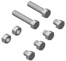
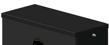

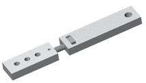

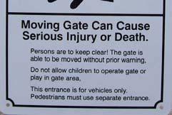
6 PARTS IDENTIFICATION Primary Arm Operator Mounting Plate Adjustable Arm Secondary Arm Fasteners CAUTION Signs (2 each) Gate Bracket Control Box 6
7 POST LOCATION GUIDE Determine the angle that the gate will open to (A). Select the post coordinates (B&C) as shown on the chart below. Distances are from the hinge square to the center of the mounting post. Longer gates should operate at the longer speeds. D A E C B A Open degrees B inches C inches D inches E inches Approximate Seconds to open Optimum

8 OPERATOR INSTALLATION STEP 1 The 3500 operator is designed for installation using a 4 x 4 square post (not supplied) with 1/4 wall thickness. 1. Determine the height on the gate where the operator will attach to. 2. Install the post as per the diagram below. The top of the post should be 2 above the centerline of the location where the gate bracket will be mounted on the gate. Gate bracket should be mounted to a structural member on the gate. Do not attach the gate bracket to pickets. 3. Conduit should be considered at this time for cable routing from control box to operator. 2 Horizontal center line of where gate bracket is to be installed IMPORTANT: The mounting post should be square to the gate in the closed position and level for proper operation. Hinge Wall or Fence Gate Distances are from the hinge to the center of the mounting post B C 8


9 STEP 2 Mount the control box as close to the operator as possible (recommended within 5 feet). Use mounting hardware capable of supporting the weight of the control box with the battery installed. Do not mount the control box where the person using the push button on the side of the box can come in contact with the gate. Set the battery inside of the control box with the terminals toward the front. (Do not use batteries with side terminals.) STEP 3 Weld the mounting bracket on top of the mounting post. The bracket should be level and square to the post. Tack welds may be made from the top side of the bracket and post. Bottom welds should be made for permanent rigidity. STEP 4 Lay the operator chassis on it s side. The two ears on the primary arm should point toward the direction the gate will close. Install the primary arm to the main drive shaft using the 1/4 key stock and tighten both set screws. The collar on the primary arm should be installed on the shaft as far as possible. Primary Arm Two Ears Key stock 9
 1/2 x 3/4 hex")


10 STEP 5 Install the drive unit on the mounting bracket using (4) 1/2 x 3/4 hex bolts and lock washers. STEP 6 Install the secondary arm to the primary arm using a 1/2 x 2-1/4 hex bolt, brass washers, and lock nut. The stop tab should be positioned away from the gate. Stop Tab STEP 7 Install the adjustable arms to the secondary arm using the 1/2 x 1-1/2 hex bolt and nut. Use the middle hole in the adjustable arm. 10

.")
11 STEP 7 Install the gate bracket to the adjustable arm using the 1/2 x 2-1/2 hex bolt, washers, and lock nut. STEP 8 Push the arms assembly up against the gate in the closed position. Make sure that the primary arm is locked into the stop tab on the secondary arm. Tack weld or c-clamp the gate bracket to the gate. Permanent welds or bolt attachment should be completed once limits are set. STEP 9 Route the cable from the control box to the operator. Connect the cable to the left side of the terminal block on the operator as shown. The operator in this manual is set up for left side installation (from inside looking at gate in closed position). For right side installation plug the 5 pin connector into INPUT B on the surge board. Left Side Installation Right Side Installation Red Black Green Orange White Red Black Green Orange White 11


 The gate should be in the")


12 STEP 10 Connect the two ring terminals on the connector end of the cable to the battery. The battery charger or solar panel should be installed at this time. Plug the connector into the Master connector on the circuit board. STEP 11 Press LED Enable on the right side of the circuit board. Turn program switch #1 off (TIMER TO CLOSE) The gate should be in the closed position. Rotate the bottom collar until the closed LED illuminates. Open the gate to the desired open position and stop the gate. Rotate the top magnet collar until the open limit LED illuminates. The close limit should be adjusted to allow the arms to lock over center but ensure that the close LED is illuminated when the gate stops. Magnet Collar - Open Magnet Collar - Close 12


 Applies battery")
13 STEP 12 The close tension on the gate can be further adjusted by: Removing the 1/2 bolt on the secondary arm (course adjustment 1-2 ). Slide the adjustable arm out and rotate counter clockwise to increase close pressure and clockwise to reduce close pressure. The three holes in the adjustable arm will allow further adjustment if necessary. EMERGENCY MANUAL OPERATION For manual operation, flip the release switch on the left underside of the operator. Pull the arms enough to disengage the lock tab and open the gate. The release switch should be reset for normal operation. Or unplug the cable from the control box and plug into the emergency bypass connector EMERGENCY BYPASS (for emergency opening only) Applies battery voltage directly to motor to open gate if control board fails. User must unplug before gate opens to maximum travel or motor will continue to run until it stalls. 13

 should be opened and closed to reset the control board.")
14 STEP 13 Programming Current Sensing The 835/836 control boards incorporate a safety feature that will put the operator into a hard shutdown mode if the control board detects a current sense two consecutive times during a cycle. This hard shutdown condition can only be reset by shorting the FIREBOX or UL connectors on the left side of the control board to ground. This condition may also be reset by pressing the HARD SHUTDOWN RESET button located toward the upper right hand corner of the control board. If a firebox is used in the installation, The firebox door (optional) should be opened and closed to reset the control board. The following instructions must be followed at installation for proper safety assurance. All limits should be set before beginning this procedure. This new procedure applies to revision 31 or higher firmware. 1. Press and hold the LED ENABLE button for five seconds and then release. The STOP LED will blink indicating that the board is in learn mode. 3. Cycle gate for 3 full cycles. The STOP LED will stop blinking indicating that the board is now ready for normal operation 4. Test the auto reverse sensitivity to ensure maximum safety protection. The current sensitivity adjustment pot may be adjusted to decrease or increase sensitivity. COUNTER CLOCKWISE More sensitivity Gate is easy to current sense CLOCKWISE Less sensitivity Gate is harder to current sense 8. Refer to the 835/836 Operator Control Board Manual to set other options such as program switch options and close timer adjustments. Installation is now complete. 14


15 835/836 Control Board Parts Identification Program Switches Timer To Close - Dual Gate Delay - Current Sensitivity - Adjustments Microprocessor GateLink Connector Hard Shutdown Reset Operate Push Button Remote Monitor Outputs and Photo Eye Optional Device Inputs LED Enable & Learn Mode Push Button Stop Circuit Jumper Control Board Reset Fire & ETL Inputs Optional Device Input Emergency Bypass Actuator Connector (Slave) Reverse Battery Polarity Indicators Actuator Connector (Master) 15
 Pin 5 Green Common for both limit switches Pin 6 Yellow Feedback from intelligent actuator(816e/816ex) Pin 7 Black Battery Negative Pin 8 Red Battery Positive EMERGENCY")

 +12V when on closed limit. Ground when off of closed limit.")
 Photo Eye Hookup Photo eye / safety loop wiring. Connect the positive power wire of the accessory to 12V.")
16 Board Actuator Cable Actuator Connector Function Pin 1 Orange Open Limit Pin 2 White Close Limit Pin 3 Black Motor (positive on open, negative on close) Pin 4 Red Motor (negative on open, positive on close) Pin 5 Green Common for both limit switches Pin 6 Yellow Feedback from intelligent actuator(816e/816ex) Pin 7 Black Battery Negative Pin 8 Red Battery Positive EMERGENCY BYPASS (open only) Applies battery voltage directly to motor to open gate if control board fails. User must unplug before gate opens to maximum travel or 15 amp fuse will open. Fuse should be checked before returning gate to service. Remote Outputs and Photo Eye Hookup 12V MAS SLV GND Supplied battery voltage Master Operator Indicator (indicates master side of gate is closed) +12V when on closed limit. Ground when off of closed limit. Slave Operator Indicator (indicates slave side of gate is closed) +12V when on closed limit. Ground when off of closed limit. Battery supplied ground SIREN Connect to siren + applies +12V when gate(s) are running, or in hard shutdown GND LOCK Battery supplied ground Connect to lock + (optional) Magnetic or Solenoid type locks (Dip Switch #6 Selectable) Photo Eye Hookup Photo eye / safety loop wiring. Connect the positive power wire of the accessory to 12V. Connect the ground wire of the accessory to MAS (upper right area of the 835/836 board). Connect the relay wires of the accessory as normal: COM to GND. NO to SAFETY (#14) (for a safety device). When the gate operator begins opening (comes off of the closed limits) the MAS terminal will become a ground and will complete the flow of power to the accessory. This will power the accessory up and it will work as normal until the gate gets closed and the MAS terminal switches and the device will power down. 16
 CURRENT SENSITIVITY")


17 Adjustments TIMER TO CLOSE Adjusts time before gate automatically closes Adjustable 5 to 70 seconds. DUAL GATE DELAY Adjusts delay between master and slave operation 0-4 seconds (836 only with magnetic, solenoid, and other locking devices) CURRENT SENSITIVITY Increases or decreases the Auto Reverse sensitivity. Push Buttons OPERATE When depressed, activates the gate. Used for initial installation and testing. Hard Shutdown Reset Resets the operator when the gate current senses twice before fully opening or closing. LED ENABLE When depressed, activates LEDs for 15 minutes to assist in installation and troubleshooting. Hold the push button down for five seconds to put the board in program mode. RESET Resets the microprocessor. Returns processor to last known state. Jumpers STOP CIRCUIT JUMPER When the STOP CIRCUIT JUMPER is connected, the gate will operate normally. STOP CIRCUIT JUMPER When a 3-button station is connected to the board, the STOP CIRCUIT JUMPER must be removed. 17
. 3 SLAVE DISABLE Enables slave side (dual gate use).")
18 Program Switches OFF ON 1 TIMER TO CLOSE Gate does not automatically close. Gate automatically closes. 2 TIMER TO CLOSE OPT. Gate automatically closes from Gate automatically closes only when completely any position after opening. open (open limit engaged). 3 SLAVE DISABLE Enables slave side (dual gate use). Disables slave side. (single gate use) 4 SIREN DELAY Siren (optional) active when gate is Siren (optional) starts 5 seconds before gate moves. moving. 5 STOP CIRCUIT ENABLE Must hold down open or close Normal operation buttons to move gate. Gate stops Momentary open or close input runs gate to limit. when button released. 6 LOCK TYPE For 12V mechanical (solenoid) locks. For 12V magnetic locks. (+12V for 4 seconds on open cycle) (+12V when on close limit) 7 COAST ENABLE Gate will brake when at Open or Gate will coast (minimally) when it reaches limits. Close limit 8 FREE EXIT OPT. A free exit input will open gate from A free exit input will open gate from any closed position or after a close cycle position after an open or close cycle. only. 9 NOT USED 10 SMART ACT. Off for 416E & 416EX actuators, Used for 816E & 816EX actuators only slide gates, 3500 or when slow down (soft start & stop). feature is not desired. 18
 Supplied Battery Ground Activate Gate (Push button activation when momentarily shorted to ground) Supplied Battery Voltage (Protected with 3 Amp fuse) Reverse edge input.")
19 Optional Device Inputs GND INP 12V GND INP 12V EDGE EDGE GND GND STOP Supplied Battery Ground Activate Gate (Push button activation when momentarily shorted to ground) Supplied Battery Voltage (Protected with 3 Amp fuse) Supplied Battery Ground Activate Gate (Push button activation when momentarily shorted to ground) Supplied Battery Voltage (Protected with 3 Amp fuse) Reverse edge input. When grounded, will stop and reverse gate if closing, resets close timer if gate is open. Reverse edge input. When grounded, will stop and reverse gate if closing, resets close timer if gate is open. Supplied Battery Ground Supplied Battery Ground Stop input from a 3 button station (must remove STOP CIRCUIT JUMPER) Normally closed CLOSE Close input from a 3 button station (see program switch #5 for options) OPEN GND GND Open input from a 3 button station (see program switch #5 for options) Supplied Battery Ground Supplied Battery Ground FREE EXIT Opens gate if closed, stops and reverses gate if closing, resets close timer if gate is open. GND Supplied Battery Ground SHADOW Resets close timer when gate is open (also referred to as under gate loop) GND SAFETY GND Supplied Battery Ground Resets close timer if gate is open, stops and reverses if gate is closing. (Does not open a closed gate) Supplied Battery Ground FIRE UL When grounded, opens gate and holds gate open until released. Clears Hard Shutdown mode of software. When grounded, opens gate and holds gate open until released. Clears Hard Shutdown mode of software. GND INP 12V Supplied Battery Ground Activate Gate (Push button activation when momentarily shorted to ground) Supplied Battery Voltage (Protected with 3 Amp fuse) 19


.")


20 APOLLO Gate Operators, Inc. 911 Siren The 911 Siren is included with all Apollo ETL Gate Operators. Mount siren in an area that will produce maximum performance (additional wire may be required). Connect the red wire to the SIREN connector on the Remote Monitor Output Connector block. Connect the black wire to the GND connector on the Remote Monitor Output Connector block. Red Black Set Program Switch # 4 as preferred: ON - Upon activation, Siren will start for 5 seconds before gate(s) begin moving. OFF - Siren and gate(s) start immediately upon activation. 20


21 APOLLO Gate Operators RECEIVER OPTIONS Do not confuse the receiver code switches with the red program switches on the gate control board. Never set all code switches to the same position. Transmitters must match code switches for proper operation. If power is taken directly from battery or connected as shown below, receiver should be configured for 12VDC Multi-Code/Digi-Code black gray gray red Allstar white black red Lift-Master* Heddolf black white yellow red Linear white/silver common n/o white/gold * Lift-Master will require that the 12/24 jumper be set to 12 and the C/M (constant/momentary) jumper be set to C 21
22 TROUBLESHOOTING OPERATOR & ACCESSORIES Some troubleshooting will require a hand held multimeter. An inexpensive digital multimeter may be purchased at Radio Shack or a local electric supply company. Refer to the owners manual for instructions. SYMPTOM Gate opens OK but after closing, opens back up. 1. Excessive closing pressure on gate. Re-adjust the close limit switch on the operator. 2. Automatic reverse sensitivity is set too sensitive. Re-adjust - CAUTION: Automatic reverse sensitivity should be set sensitive enough to avoid injury. 3. Gate is mechanically binding. Disconnect operator from gate and eliminate binding. 4. Battery voltage is too low. Battery voltage should be 12 to 14 volts under load. Check solar panel output or battery charger output or re-evaluate usage. 5. Replace circuit board. SYMPTOM Gate moves only a few feet, then stops or reverses. 1. Battery voltage is too low. Battery voltage should be 12 to 14 volts under load. Check solar panel output or battery charger output or re-evaluate usage. 2. Verify that program switch #10 is off 3. Gate is mechanically binding. Disconnect operator from gate and eliminate binding. 4. Current sensitivity is adjusted too sensitive. Re-adjust current sensitivity. 5. Re learn the circuit board by holding down the LED Enable push button for 5 seconds and cycle gate until LEDs stop blinking. 6. Replace circuit board 22
23 SYMPTOM Gate will open using push button on side of box, but not with transmitter. 1. Code switches do not match. Check that the code switches in the transmitter and the receiver match. 2. Low or dead battery in transmitter. Replace battery. 3. Fuse blown on circuit board. Check fuses on gate control board. 4. Low battery in operator. Battery voltage should be 12 to 14 volts under load. 5. Replace receiver. SYMPTOM Transmitter works, but not very far. Note: Transmission distances will vary according to terrain, obstructions, and electrical interference. The normal range from inside a vehicle is feet while feet may be obtained from outside the vehicle. 1. Low battery in transmitter. Replace battery. 2. Transmitter malfunctioning. Try a different transmitter. 3. Antenna not making good connection. Be sure center conductor of antenna is penetrating the female connector on the side of the gate box. 4. Reception is being blocked. Raise the height of the antenna using a #244 antenna extension kit. 5. Replace receiver. SYMPTOM Gate randomly opens, closes, or stops for no reason. 1. Transmitter is stuck on. Check all transmitters, keypads, pushbuttons, etc. for a stuck button. 2. Transmitter and receiver code switches are all down, up, or in the middle. Change at least one switch position in the transmitter and receiver. 3. Push button on side of control box is defective. Disconnect and test. 23


24 SYMPTOM Gate will not open or close. Short the GND and UL connections on the lower left set of connectors and test. Disconnect the solar panel or charger and measure the battery voltage. Battery should read 12 or more volts and never drop below 11 volts when gate is operating. Reset program switches to factory settings.. Single Boards # 1, # 2, # 3, # 5, # 9, ON, all others OFF Dual Boards # 1, # 2, # 5, # 9 ON, all others OFF *Be sure to turn Switch # 9 OFF during normal operation. 1 ON 2 ON 3 ON 4 off 5 ON 6 off 7 off 8 off 9 NOT USED 10 off Disconnect all accessories from the circuit board - receivers, push buttons, keypads, loops, phones, intercoms, etc. Activate the operator by momentarily shorting GND to INP on one of the three pin connectors. If the operator works, reconnect each accessory individually starting with push button and test operation. Disconnect operator from circuit board and inspect pins in the connector for damage or poor connections. Check for proper limit switch configuration (multimeter required) on the cable from the operator to the control box: GATE IN OPEN POSITION...Orange & Green wires are shorted, White & Green wires are open. GATE IN CLOSED POSITION.. White & Green wires are shorted, Orange & Green wires are open. GATE IN MID TRAVEL... White, Green, & Orange wires are open, no shorts. Replace circuit board. 24
25 LIMITED TWO-YEAR WARRANTY Apollo Gate Operators are warranted against defects for a period of 24 months from the date of purchase, providing recommended installation procedures are followed. This warranty is in lieu of all other warranties expressed or implied (some states do not allow limitations on how long an implied warranty lasts, so this limitation may not apply to you) and shall be considered void if damage was due to improper installation or use, connection to improper power source, or if damage was caused by fire, flood, or lightning. The manufacturer will not be responsible for any labor charges incurred in the removal or replacement of defective parts. In case of failure due to defective material or workmanship during the warranty period, the defective part will be repaired or replaced at the manufacturer s option at no charge if returned freight prepaid. New or factory rebuilt replacements may be used. Replacement parts are warranted for the remaining portion of the original warranty period. The manufacturer will pay standard ground freight on the return of repaired or replaced items in warranty. 25
HYPPOETL HYPPO DUALETL 12 VOLT DC Swing Gate Operator
 HYPPOETL HYPPO DUALETL 12 VOLT DC Swing Gate Operator Manufactured by NICE SpA INSTALLATION MANUAL 08/10 CONTENTS IMPORTANT SAFETY INSTRUCTIONS... 3 Applications...... 4 Pre-Installation Checklist... 5
Model 1550 Single Swing Gate Model 1650 Dual Swing Gate
 Gate Operators, Inc. Model 1550 Single Swing Gate Model 1650 Dual Swing Gate Swing Gate Operator CONTENTS Safety Precautions... 2 Applications... 3 Pre-Installation Checklist... 4 Parts Identification...
Operators, Inc. Model 1550ETL Single Swing Gate Operator Model 1650ETL Dual Swing Gate Operator INSTALLATION MANUAL 04/07
 APOLLO Gate Operators, Inc. Model 1550ETL Single Swing Gate Operator Model 1650ETL Dual Swing Gate Operator INSTALLATION MANUAL 04/07 CONTENTS IMPORTANT SAFETY INSTRUCTIONS... 3 Applications... 4 Pre-Installation
APOLLO Gate Operators, Inc.
 APOLLO Gate Operators, Inc. Model BA12 12 VOLT DC BARRIER ARM OPERATOR INSTALLATION MANUAL 0707 CONTENTS IMPORTANT SAFETY INSTRUCTIONS... 3 Applications... 4 Pre-Installation Checklist... 5 Operator Installation...
APOLLO Gate Operators, Inc.
 APOLLO Gate Operators, Inc. Model 7200ETL Post Mounted Residential & Heavy Duty Commercial Slide Gate Operator INSTALLATION MANUAL 04/11 CONTENTS IMPORTANT SAFETY INSTRUCTIONS... 3 Applications... 4 Pre-Installation
Gate Operators, Inc. Model 7100UL Residential & Medium Duty Commercial Slide Gate Operator INSTALLATION MANUAL
 Gate Operators, Inc. Model 7100UL Residential & Medium Duty Commercial Slide Gate Operator INSTALLATION MANUAL 10-04-00 CONTENTS Safety Precautions... 2 Applications... 3 Pre-Installation Checklist...
APOLLO Gate Operators, Inc.
 POLLO Gate Operators, Inc. Model 7000TL Post Mounted esidential & Medium Duty Commercial Slide Gate Operator Now with new current sense adjustment procedure - see page 11 INSTLLTION MNUL 051004 CONTNTS
APOLLO Gate Operators, Inc.
 POLLO Gate Operators, Inc. Model 7000TL Post Mounted esidential & Medium Duty Commercial Slide Gate Operator INSTLLTION MNUL 04/07 CONTNTS IMPOTNT SFTY INSTUCTIONS... 3 pplications... 4 Pre-Installation
INSTALLATION M ANUAL
 INSTALLATION MANUAL Table of Contents UL Listings Installing the Warning Sign / Precautions Methods of Installation / Compact Installation Mounting the Secondary Entrapment / Welding Gate Arn Mounting
Linear Actuator Swing Gate Operator Installation Manual Model # LA405-24
 Linear Actuator Swing Gate Operator Installation Manual Model # LA405-24 2 Contents Contents Product Information and Specs. 3 Mechanical 3 Electrical, Line Connections 3 Electrical, Control Connections
Installation and Maintenance Manual
 Installation and Maintenance Manual Swing Gate Operator Model HL410-21 & HL410L-21 2 Contents Contents Parts & Components 3 Specifications & Capacities 4 Safety Information 6 Installer 6 End User 7 General
Nice Apollo Swing Gate Opener Model 1500
 Nice Apollo Swing Gate Opener Model 500 Model 600 Vehicular Swing Gate Opener Revision.0.0.0_-04 TABLE OF CONTENTS EXTREMELY IMPORTANT TECHNICAL SPECIFICATIONS - OVERVIEW - GATE INFORMATION. - ASTM F00.
6002 swing gate actuator - installation guide
 600 swing gate actuator - installation guide 600 Residential Swing Gate Actuator Installation Guide DKS DoorKing, Inc. 0 Glasgow, Avenue Inglewood, Ca. 900 0.645.00 0.64.586 fax info@doorking.com www.doorking.com
RAMSET
 RAMSET TABLE OF CONTENTS Important Safety Requirements & Instructions...1 Responsibilities of Installers and Technicians...2 Important Safety Requirements by UL Standards...3 Classes of Vehicular Gate
RAMSET RAM
 www.ramsetinc.com TABLE OF CONTENTS Important Safety Requirements & Instructions...1 Responsibilities of Installers and Technicians...2 Important Safety Requirements by UL Standards...3 Classes of Vehicular
PowerMaster MODEL MBG. Installation Manual U L R UL 325 AND UL 991 LISTED MEDIUM DUTY BARRIER GATE OPERATOR TABLE OF CONTENTS
 PowerMaster TABLE OF CONTENTS MODEL MBG MEDIUM DUTY BARRIER GATE OPERATOR Important Safety Information...... 3 System Designer Safety Instructions.......4 Installer Safety Instructions....... 5 Installation
Instruction Manual for the. E-SL 450 Series
 Instruction Manual for the E-SL 450 Series Estate Slide Summary of Functions The Estate Slide is only to be used for vehicular Slide gates in a Class I setting. Class I: A vehicular gate opener (or system)
Gate & Door Controller with LCD and Intelligent Technology
 2nd Edition Gate & Door Controller with LCD and Intelligent Technology 24Sv1 and 12Sv1 Motor Controllers Setup and Technical information for single motor controller for gates & doors Includes latest Intelligent
Installation/Owners Manual PATRIOT RSL Vehicular Slide Gate Operator Heavy Duty Battery Powered Solar or AC Charged
 Installation/Owners Manual PATRIOT RSL Vehicular Slide Gate Operator Heavy Duty Battery Powered Solar or AC Charged WARNING TO REDUCE THE RISK OF INJURY OR DEATH 1. READ AND FOLLOW ALL INSTRUCTIONS 2.
INSTALLATION INSTRUCTIONS AND OPERATION MANUAL
 INSTALLATION INSTRUCTIONS AND OPERATION MANUAL UL325-2010 Compliant Commercial and Industrial Door Operator Logic Control Continuous Duty IMPORTANT INSTALLATION INSTRUCTIONS WARNING To reduce the risk
TEL: G&C Electronics CC E. T.
 TEL: +27 21 448 6774 G&C Electronics CC FAX: +27 21 447 7794 E. T. CK 89/31531/23 E-mail : etsystems@icon.co.za Internet: www.et.co.za 15 Nelson Road P.O. Box 34524 Observatory Groote Schuur Cape Town
Nice Apollo Swing. Model 36001K. Vehicular Swing Gate Operator. Revision _2-2014
 Nice Apollo Swing Gate Opener Model 35001K Vehicular Swing Gate Operator Revision 1.0.0.0_2-2014 Model 36001K TABLE OF CONTENTS CAUTIONS AND NOTES 4 EXTREMELY IMPORTANT 4 ETL DEFINITIONS COMPLIANT TO
Installation/Owners Manual
 Installation/Owners Manual PATRIOT I Single Swing Gate Operator PATRIOT II Dual Swing Gate Operator Heavy Duty Battery Powered Solar or AC Charged WARNING TO REDUCE THE RISK OF INJURY OR DEATH 1. READ
AUTOMATIC GATE LOCK. Installation Manual
 IMPORTANT: Before you install the automatic gate lock be sure your gate is level, moves freely on its hinges, and does not bind or drag against the ground. AUTOMATIC GATE LOCK Installation Manual PLEASE
FOR CLASS I, II, III, IV VEHICULAR GATE OPERATORS
 Ramset_Man300.qxd 4/18/05 1:06 PM Page 1 FOR CLASS I, II, III, IV VEHICULAR GATE OPERATORS Ramset_Man300.qxd 4/18/05 1:06 PM Page 2 www.ramsetinc.com Ramset_Man300.qxd 4/18/05 1:06 PM Page 3 TABLE OF CONTENTS
ontrol Systems, Inc. Swing Gate Installation Manual Eagle-200 Series Eagle-100 Series UL325 and UL991 Compliant
 Swing Gate Installation Manual Eagle-200 Series Eagle-100 Series ontrol Systems, Inc. www.eagleoperators.com Operator installation and instructions for the Eagle-200 and Eagle-100 Series. UL325 and UL991
General Information...3. Features...5. Parts Identification...6. Installation...8. Alternate Installation Electrical Fine Tuning...
 pg 1 Contents Pg. General Information...3 Features...5 Parts Identification...6 Installation...8 Alternate Installation...12 Electrical...13 Fine Tuning...17 Master and Slave...18 Wiring Diagrams...19
Owner s Manual. Model 9300 Vehicular Slide Gate Operator
 Owner s Manual Model 9300 Vehicular Slide Gate Operator DoorKing, Inc. 120 Glasgow Avenue Inglewood, California 90301 U.S.A. Phone: 310-645-0023 Fax: 310-641-1586 www.doorking.com P/N 9300-065 Rev C 6/03
115 VAC Control Boxes for
 CLASS 582 HP OPEN CLOSE Wiring / Owner s Manual Use this manual for circuit board 02-010 Revision A or higher. 115 VAC Control Boxes for 6002, 600, 600 and 600 gate operators 02-065-E-5-12 CFORMS TO ANSI/UL-25
FOR CLASS I, II, III, IV VEHICULAR GATE OPERATORS
 R_Ramset_Ram3000.qxd 8/19/05 4:56 PM Page 1 FOR CLASS I, II, III, IV VEHICULAR GATE OPERATORS R_Ramset_Ram3000.qxd 8/19/05 4:56 PM Page 2 www.ramsetinc.com R_Ramset_Ram3000.qxd 8/19/05 4:56 PM Page 3 TABLE
Owner s Manual. Models 6050 and 6100 Vehicular Swing Gate Operators
 Owner s Manual Models 6050 and 6100 Vehicular Swing Gate Operators DoorKing, Inc. 120 Glasgow Avenue Inglewood, California 90301 U.S.A. Phone: 310-645-0023 Fax: 310-641-1586 www.doorking.com P/N 6050-065
115 VAC Control Boxes for
 CLASS MODEL SERIAL 58 HP CLOSE Wiring / Owner s Manual Use this manual for circuit board 0-010 Revision A or higher. EXTERNAL ENTRAPMENT PROTECTI MUST be installed or the gate operator WILL NOT function.
Solar Control Box for
 CLASS MODEL SERIAL 53382 HP CLOSE Wiring / Owner s Manual Use this manual for circuit board 4302-010 Revision N or higher. Solar Control Box for 6002, 6003, 6004 and 6400 gate operators 4302-067-N-2-13
RAM TABLE OF CONTENTS
 TABLE OF CONTENTS Important Safety Requirements & Instructions...1 Responsibilities of Installers and Technicians...2 Important Safety Requirements by UL Standards...3 Classes of Vehicular Gate Operators...4
115 VAC Control Boxes for
 CLASS MODEL SERIAL 8 HP DOORKING CLOSE Wiring / Owner s Manual Use this manual for circuit board 0-00 Revision AA or higher. EXTERNAL ENTRAPMENT PROTECTI MUST be installed or the gate operator WILL NOT
Actuator Arm and Control Box Mounting
 Actuator Arm and Control Box Mounting To wire this operator and complete the installation, refer to a specific control box Wiring/Owner s manual. 6002 Vehicular Swing Gate Operator 6002-065-Y-1-13 Copyright
ACSI MODEL 1406BB-04-AO POWER SUPPLY INSTALLATION INSTRUCTIONS
 II 1400-10 ACSI MODEL 1406BB-04-AO POWER SUPPLY INSTALLATION INSTRUCTIONS Features: Up to 1.95 Amps Load Capacity Class 2 Rated Outputs Overload, Over Voltage, and Short Circuit Protection Standby Battery
User Manual 500 & 700
 User Manual 500 & 700 Polaris 700/702 Polaris 500/502 Warning: Before installing your Polaris Automatic Gate operator (sometimes also referred to as the Product ), read this entire Installation Manual
Installation/Owners Manual
 Installation/Owners Manual Ranger I Single Swing Gate Operator Ranger II Dual Swing Gate Operator Heavy Duty Battery Powered Solar or AC Charged WARNING TO REDUCE THE RISK OF INJURY OR DEATH 1. READ AND
MODEL D-SBG Single Arm Barrier Gate Operator
 INSTALLATION AND OWNER S MANUAL MODEL D-SBG Single Arm Barrier Gate Operator UL 325 and UL 991 Listed WITH NITRO BOARD (SEE SUPPLEMENTAL MANUAL) Serial #: Date Installed: Your Dealer: READ THIS MANUAL
General Information...3. Features...5. Parts Identification...6. Installation...8. Alternate Installation Electrical Fine Tuning...
 pg 1 Contents Pg. General Information...3 Features...5 Parts Identification...6 Installation...8 Alternate Installation...12 Electrical...13 Fine Tuning...17 Master and Slave...18 Wiring Diagrams...19
COMMANDO REMOTE CONTROL ENGINE STARTER. Limited Warranty Statement MADE IN THE U.S.A. IMPORTANT KEEP YOUR INVOICE WITH THIS WARRANTY STATEMENT!
 Limited Warranty Statement GNU COMMANDO LINE WARRANTY STATEMENT GNU warrants this product to be free from defects in material and workmanship for a period of one (1) year from the date of sale to the original
ARCHITECTURAL CONTROL SYSTEMS, INCORPORATED ST. LOUIS, MISSOURI
 II 1400-6 ARCHITECTURAL CONTROL SYSTEMS, INCORPORATED ST. LOUIS, MISSOURI ACSI 1426-04-AO ELECTRIC LATCH RETRACTION CONTROLLER INSTALLATION INSTRUCTIONS I.D. 1092, REV. C INSTALLATION For C-UL Listed applications,
T5-ETL-1K T7-ETL-1K 12 VOLTS DC Swing Gate Operator
 T5-ETL-1K T7-ETL-1K 12 VOLTS DC Swing Gate Operator INSTALLATION MANUAL 1 Rev 1.0 Table of contents IMPORTANT SAFETY INSTRUCTIONS...II APPLICATION. III PRE-INSTALLATION CHECKLIST........ IV PART IDENTIFICATION.....
Model 579 Curtain Machine Manual. General Information. Unpacking:
 Model 579 Curtain Machine Manual. General Information The Model 579 curtain machine is designed for use with most light duty commercial and residential drapery tracks. The 579 curtain machine is designed
MD10. Engine Controller. Installation and User Manual for the MD10 Engine Controller. Full Version
 MD10 Engine Controller Installation and User Manual for the MD10 Engine Controller. Full Version File: MartinMD10rev1.4.doc May 16, 2002 2 READ MANUAL BEFORE INSTALLING UNIT Receipt of shipment and warranty
copyright 2008 chamberlain professional products -
 copyright 2008 chamberlain professional products - www.liftmaster.com TABLE OF CONTENTS Role of Specifiers and Designers Role of Dealers, Installers and Trained Gate System Technicians Role of End Users
INSTALLATION INSTRUCTIONS AND OPERATION MANUAL
 INSTALLATION INSTRUCTIONS AND OPERATION MANUAL NEMA 4X UL325-2010 Compliant Commercial and Industrial Door Operator Logic Control Continuous Duty IMPORTANT INSTALLATION INSTRUCTIONS WARNING To reduce the
For Classes I, II, III, IV
 For Classes I, II, III, IV pg 1 Contents Pg. General Information...3 Features...5 Parts Identification...6 Installation...8 Alternate Installation...12 Electrical...13 Fine Tuning...17 Master and Slave...18
FOR CLASS I VEHICULAR GATE OPERATORS
 FOR CLASS I VEHICULAR GATE OPERATORS www.ramsetinc.com TABLE OF CONTENTS Important Safety Requirements & Instructions.... 1 Responsibilities of Installers and Technicians. 2 Important Safety Requirements
AUTOMATIC GATE OPENER
 AUTOMATIC GATE OPENER INSTALLATION MANUAL Model G750 For Single Gates AUTOMATIC GATE OPENER Installation Manual GATE OPENER CLASS CATEGORIES* The Zareba Automatic Gate Opener is intended for use with vehicular
INSTALLATION INSTRUCTIONS AND OPERATION MANUAL
 INSTALLATION INSTRUCTIONS AND OPERATION MANUAL FS Series Rolling Fire Door Operators UL325-2010 Compliant Restricted Duty Operators CORPORATION IMPORTANT INSTALLATION INSTRUCTIONS WARNING To reduce the
TC26-B Vehicle Sensor
 Section 1 General Description The Model TC26-B is a microprocessor controlled vehicle sensor with a variable range. It is designed to trigger the operation of a traffic controller. The TC26-B will only
INSTALLATION INSTRUCTIONS AND OPERATION MANUAL
 INSTALLATION INSTRUCTIONS AND OPERATION MANUAL - 1/3, 1/2, 3/4hp UL325-2010 Compliant Commercial and Industrial Door Operator Logic Control Duty Cycle 20 Cycles per Hour IMPORTANT INSTALLATION INSTRUCTIONS
INSTALLATION & OWNER'S MANUAL
 INSTALLATION & OWNER'S MANUAL THE EAGLE POWER I BATTERY BACK UP PHONE (818) 764-6690 / TOLL FREE (800) 708-8848 PRE INSTALLATION INSTRUCTIONS BEFORE PROCEEDING WITH INSTALLATION READ THIS MANUAL THOROUGHLY
INSTALLATION INSTRUCTIONS AND OPERATION MANUAL
 INSTALLATION INSTRUCTIONS AND OPERATION MANUAL Commercial and Industrial Fire Door Operator Logic Control Restricted Duty Fire Door Operators IMPORTANT INSTALLATION INSTRUCTIONS WARNING To reduce the risk
12V DC MOTORISED OPENER FOR SWING GATES Section Table of Contents Page
 12V DC MOTORISED OPENER FOR SWING GATES Section Table of Contents Page 1 Introduction 2 2 Warnings 4 3 Technical Specifications 5 4 Positioning 6 5 Wiring Diagram 7 6 Standard Installation Kit 8 7 Installation
Owner s Manual. Overhead Gate Operator. Copyright 2015 DoorKing, Inc. All rights reserved. REV SENSE OPEN GATE FORCED NO NC
 Owner s Manual 50 Overhead Gate Operator EXIT PART REVERSE TIME DELAY REV SENSE OPEN REV SENSE CLOSE 2 3 4 5 6 7 8 2 3 4 PUSH TO OPERATE technician use only GATE FORCED NO NC Copyright 205 DoorKing, Inc.
Installation/Owner s Manual Series 6500
 Installation/Owner s Manual Series 00 Use this manual for circuit board 0-08 Revision A or higher. Vehicular Swing Gate Operator Entrapment Protection must be provided for the gate system where the risk
Solar Control Box for
 CLASS MODEL SERIAL 5338 HP D OOR KIN G OPEN CLOSE Wiring / Owner s Manual Use this manual for circuit board 430-010 Revision AA or higher. EXTERNAL ENTRAPMENT PROTECTI MUST be installed or the gate operator
FSW 900 Swing Gate Operator
 FSW 900 Swing Gate Operator UL325 - UL991 FAAC International Inc. Headquarter & East Coast Operations 3160 Murrell Rd Rockledge, FL 32955 Tel. 800 221 8278 www.faacusa.com FAAC International Inc. West
vehicular gate operator installation instructions and safety information revision B1 april 2007 CLASS I, CLASS II, CLASS III and CLASS IV
 revision B1 april 2007 installation instructions and safety information LISTED 18TC UL 325 UL 991 vehicular gate operator G-5 CLASS I, CLASS II, CLASS III and CLASS IV PARTS DIAGRAM 4 5 10 12 10 16 13
UGP-712 Vehicular swing gate operator
 Vehicular swing gate operator INSTALLATION INSTRUCTION MANUAL PLATINUM ACCESS SYSTEMS Installation Instructions & Safety Information Manual Vehicular Swing Gate Operator Class I, Class II, Class III, and
3 Year SENTRY 300 S / 300 D. Installation/Owners Manual. High Quality Low Voltage Vehicular Swing Gate Opener
 SENTRY 300 S / 300 D High Quality Low Voltage Vehicular Swing Gate Opener Battery Powered Solar or AC Charged Installation/Owners Manual 3 Year Warranty Designed to open all types of gates in all kinds
Two Channel Remote Shutdown Device
 Installation & Operation Standard Features: Two Channel Remote Shutdown Device I. Introduction Latched shutdown for increased safety Powerful transmitter with 300 feet range Waterproof sealed transmitter
DOOR LIMITS A) ENGAGE CHAIN/BELT CONNECTOR TO CARRIAGE CAUTION B) CLOSE TRAVEL LIMIT
 ENGAGE CHAIN/BELT CONNECTOR TO CARRIAGE CAUTION B) CLOSE TRAVEL LIMIT") 20 6 DOOR LIMITS Severe injury or death can result if the door closing force is set too high. Never increase the door closing force above the minimum required to move the door. Never adjust force to compensate
20 6 DOOR LIMITS Severe injury or death can result if the door closing force is set too high. Never increase the door closing force above the minimum required to move the door. Never adjust force to compensate
IMPORTANT: Before you install the automatic gate lock be sure your gate is level, moves freely on hinges, and is free from binding and/or dragging.
 Before You Start... IMPORTANT: Before you install the automatic gate lock be sure your gate is level, moves freely on hinges, and is free from binding and/or dragging. For the GTO Automatic Gate Lock work
Heavy Duty Commercial Linear Gate Operator
 MAX SUPER ARM 2300 Heavy Duty Commercial Linear Gate Operator Moves heavy gates up to 20 High traffic high wind Self-locking, Mag Lock unnecessary Overload clutch release on 3 ton impact MAX AC control
Owner s Manual. Series 6300 Vehicular Swing Gate Operators
 Owner s Manual Series 6300 Vehicular Swing Gate Operators DoorKing, Inc. 120 Glasgow Avenue Inglewood, California 90301 U.S.A. Phone: 310-645-0023 Fax: 310-641-1586 www.doorking.com P/N 6300-065 REV E,
Nice Apollo Swing Gate Opener
 Nice Apollo Swing Gate Opener Vehicular Swing Gate Operator Model T5ETL-1K Model T7ETL-1K Revision 1.0.0.0_2-2014 TABLE OF CONTENTS CAUTIONS AND NOTES 4 EXTREMELY IMPORTANT 4 ETL DEFINITIONS COMPLIANT
Installation/Owner s Manual Series 6500
 Installation/Owner s Manual Series 00 Use this manual for circuit board 0-00 Revision E or higher. EXTERNAL ENTRAPMENT PROTECTI MUST be installed or the gate operator WILL NOT function. Vehicular Swing
INSTALLATION INSTRUCTIONS AND OPERATION MANUAL
 INSTALLATION INSTRUCTIONS AND OPERATION MANUAL Cornell RG Operator RGRL Series (w/ Internal Interlock sensor) ES 10-288 GENERAL NOTES TO REDUCE THE RISK OF SEVERE INJURY OR DEATH, READ AND FOLLOW ALL INSTALLATION
MODEL MSW Medium Duty Swing Gate Operator
 INSTALLATION AND OWNER S MANUAL MODEL MSW Medium Duty Swing Gate Operator UL 325 and UL 991 Listed 22-1/4 16-1/2 19-1/2 16 20'' LENGTH X 14-3/4'' WIDTH 2 O.D. PIPE (BY OTHERS) Serial #: Date Installed:
Cable/Gate Lock INSTALLATION MANUAL
 ACCESS CONTROLS WIRELESS Cable/Gate Lock INSTALLATION MANUAL This convenient battery powered wireless lock has many uses, including; multiple user access to property, securing items such as boats or trailers
Eagle Access Control Systems, Inc. / (800) / (3)
 / (3)") UL Listings IMPORTANT SAFETY INSTRUCTIONS A. WARNING To reduce the risk of injury or death: 1) READ AND FOLLOW ALL INSTRUCTIONS. 2) Never let children operate or play with gate controls. Keep the remote
UL Listings IMPORTANT SAFETY INSTRUCTIONS A. WARNING To reduce the risk of injury or death: 1) READ AND FOLLOW ALL INSTRUCTIONS. 2) Never let children operate or play with gate controls. Keep the remote
Owner s Manual. Model 9100 Vehicular Slide Gate Operator
 Owner s Manual Model 9100 Vehicular Slide Gate Operator DoorKing, Inc. 120 Glasgow Avenue Inglewood, California 90301 U.S.A. Phone: 310-645-0023 Fax: 310-641-1586 www.doorking.com P/N 9100-065 REV C, 1/04
Nice Apollo Slide Gate Opener
 Nice Apollo Slide Gate Opener Vehicular Slide Gate Operator Model 72001K Revision 1.0.0.0_2-2014 TABLE OF CONTENTS CAUTIONS AND NOTES 4 EXTREMELY IMPORTANT 4 ETL DEFINITIONS COMPLIANT TO UL325 4 1 - OVERVIEW
Installation/Owner s Manual Model 9050
 8 CLASS HP MODEL VOLTS PHASE AMPS 0 Hz MAX GATE LOAD DoorKing, Inc., Inglewood, CA Installation/Owner s Manual Model 900 Use this manual for circuit board 70-00 Revision AA or higher. Vehicular Slide Gate
INSTALLATION INSTRUCTIONS AND OPERATION MANUAL
 INSTALLATION INSTRUCTIONS AND OPERATION MANUAL FS Series Rolling Fire Door Operators CORPORATION GENERAL NOTES TO REDUCE THE RISK OF SEVERE INJURY OR DEATH, READ AND FOLLOW ALL INSTALLATION INSTRUCTIONS
AC Powered. AC Powered. Model Installation/Owner s Manual. UL 325 Compliant. AC Powered Vehicular Swing Gate Operator
 Installation/Owner s Manual Model 652-080 AC Powered Vehicular Swing Gate Operator Use this manual for circuit board 100-010 Revision AA or higher. EXTERNAL ENTRAPMENT PROTECTI MUST be installed or the
Installing the gate post bracket with the cardboard arm template
 ......... Installing the gate post bracket with the cardboard arm template... Installing gate posts brackets and arms for Push-to-Open or Pull-to-Open gates... Connection of Power Source 240Vac or Solar...
INSTALLATION INSTRUCTIONS AND SAFETY INFORMATION FOR THE VIKING G-5 GATE OPERATOR SINGLE AND DUAL GATE SYSTEMS
 INSTALLATION INSTRUCTIONS AND SAFETY INFORMATION FOR THE VIKING G-5 GATE OPERATOR SINGLE AND DUAL GATE SYSTEMS CLASS I, CLASS II, CLASS III, AND CLASS IV Residential and Commercial Vehicular Swing Gate
MODEL D-WBG Wishbone Arm Barrier Gate Operator
 INSTALLATION AND OWNER S MANUAL MODEL D-WBG Wishbone Arm Barrier Gate Operator UL 325 and UL 991 Listed WITH NITRO BOARD (SEE SUPPLEMENTAL MANUAL) Serial #: Date Installed: Your Dealer: READ THIS MANUAL
Nice Nice Swing Gate Opener. Model 1550
 Nice Nice Swing Gate Opener Model 1550 Revision 2.0.0.0_7-2018 TABLE OF CONTENTS 1 - OVERVIEW 4 2 - SAFETY INFORMATION 6 3 - Use of Vehicle Detectors 9 4 - Gate Construction and Safety 9 5 - Maintenance
AC Powered. AC Powered. Model Installation/Owner s Manual. AC Powered Vehicular Swing Gate Operator. UL 325 August 2018 Standard
 Installation/Owner s Manual Model 6524-380 AC Powered Vehicular Swing Gate Operator Use this manual for circuit board 4100-018 Revision A or higher. Entrapment Protection must be provided for the gate
Installation Instructions
 Installation Instructions MX3635-01 Rev. E Models HydraSwing 40s HydraSwing 40F 4,000 lb (1,814 kg) 10-15 seconds HydraSwing 40 4,000 lb (1,814 kg) 15-20 seconds HydraSwing 40 Twin 4,000 lb (1,814 kg)/leaf
Owner s Manual. Model 9150 Vehicular Slide Gate Operator
 Owner s Manual Model 9150 Vehicular Slide Gate Operator DoorKing, Inc. 120 Glasgow Avenue Inglewood, California 90301 U.S.A. Phone: 310-645-0023 Fax: 310-641-1586 www.doorking.com P/N 9150-065 REV D, 5/07
Please DO NOT Touch me!... Unless you are an Authorized Service Technician!
 V 0503 TABLE OF CONTENTS N T Attention: This handbook is exclusively for qualified installation personnel, and assistance and/or maintenance service. - The performances indicated in this handbook are valid
Owner s Manual. Model 9310 Vehicular Slide Gate Operator
 Owner s Manual Model 930 Vehicular Slide Gate Operator DoorKing, Inc. 20 Glasgow Avenue Inglewood, California 9030 U.S.A. Phone: 30-65-0023 Fax: 30-6-586 www.doorking.com P/N 930-065 Rev D 5/05 Copyright
INSTALLATION INSTRUCTIONS AND OPERATION MANUAL
 INSTALLATION INSTRUCTIONS AND OPERATION MANUAL - 1/3, 1/2, 3/4hp UL325-2010 Compliant Commercial and Industrial Door Operator Logic Control Duty Cycle 20 Cycles per Hour IMPORTANT INSTALLATION INSTRUCTIONS
INSTALLATION INSTRUCTIONS & MANUAL BOOK FOR ARCHITECTS, GENERAL CONTRACTORS & DEALERS REV-2
 INSTALLATI INSTRUCTIS & MANUAL BOOK FOR ARCHITECTS, GENERAL CTRACTORS & DEALERS REV-2 C Applied Applied MODEL: MIRACLE 1 HIGH-QUALITY, MECHANICAL, LINEAR OPERATOR FOR SWING GATES COPYRIGHT 1998 ELITE ACCESS
AgriWheel Single Gate Kit Low Voltage & Solar. Installation & Operating Instructions
 AgriWheel Single Gate Kit Low Voltage & Solar Installation & Operating Instructions Thank you for purchasing you AgriWheel system. Please remove the lids from both the machine and control box and remove
SWING GATE OPENERS 24V DC GEAR MOTOR
 SWING GATE OPENERS 24V DC GEAR MOTOR FOR RESIDENTIAL USER MANUAL Flashing Light Push Button Control box Gate 2 Gate 1 Index 1. Warnings 2 4. Technical Characteristics 16 2. Product Description 2.1 Applications
Certification and Product Usage Inside Back Cover ACCESS SYSTEMS
 TABLE OF CONTENTS ontents RESIDENTIAL LINEAR ACTUATOR POST MOUNT OPERATORS PRO-SW2000XL Swing Gate Operator 2 PRO-SW4000XL Swing Gate Operator 3 RESIDENTIAL POST OR PAD MOUNT CHAIN DRIVE SLIDE GATE OPERATOR
E-SL 450BD Series INSTRUCTION MANUAL WARNING USER DRIVEN MANUAL*
 USER DRIVEN MANUAL* Any feedback, changes, or advice we are glad to hear it. Please contact us at support@estateswing.com WARNING Read all instructions before beginning installation or use of this gate
Nice Apollo Swing Gate Opener 1712/ VDC
 Nice Apollo Swing Gate Opener 1712/1812-12VDC Vehicular Gate Control Unit 1724/1824-24VDC Revision 1.0.0.0_02-2014 TABLE OF CONTENTS CAUTIONS AND NOTES 5 EXTREMELY IMPORTANT 5 ETL DEFINITIONS COMPLIANT
AUTOMATIC GATE OPENER
 AUTOMATIC GATE OPENER Part # 7001282.001 Rev.A INSTALLATION MANUAL Model G752 For Double Gates AUTOMATIC GATE OPENER Installation Manual GATE OPENER CLASS CATEGORIES* The Zareba Automatic Gate Opener is
Instruction Manual. Model RAM-1000 UL & RAM-5500 UL For Class I, II, III, IV Vehicular Gate Operators. No Rev
 Rev 060202 Instruction Manual Model RAM-1000 UL & RAM-5500 UL For Class I, II, III, IV Vehicular Gate Operators C No. 545327 US TABLE OF CONTENTS Important Safety Requirements & Instructions.......................................1,2
IV. PROOF OF PURCHASE: A warranty claim must be accompanied by proof of the date of purchase.
 PD9100 / 9200 SERIES POWER CONVERTER OWNERS MANUAL PROGRESSIVE DYNAMICS, INC. POWER CONVERTER LIMITED WARRANTY I. LIMITED WARRANTY: Progressive Dynamics, Inc. warrants its power converter to be free from
Table of Contents. General Safety Preparation for Installation Parts List Optional Accessories Part List... 5
 REV 12a Table of Contents General Safety....... 2 Preparation for Installation....... 3 Parts List....... 4 Optional Accessories Part List...... 5 Technical Specifications & Feature...... 5 Installation