Operating instructions Gear Boxes and Geared Motors ZUVERLÄSSIG ANTREIBEND EFFIZIENT
|
|
|
- Simon Small
- 6 years ago
- Views:
Transcription


1 Operating instructions Gear Boxes and Geared Motors ZUVERLÄSSIG NTREIBEND EFFIZIENT Edition 05/2016
2
3 Table of contents 1. Introduction Scope and application of the gear units and geared motors Basic descriptions of the gear units and geared motors with drawings of replacement parts and parts list Worm gear Units and worm gear motors Bevel helical gear units and bevel helical geared motors Worm helical gear units and worm helical geared motors Helical worm gears and helical worm gear motors Bevel gear units and bevel geared motors Condition on delivery and warranty Transportation and storage Installation and commissioning Gear units and geared motors with projecting shaft ends Hollow shaft gear units and geared motors Installing couplings or other components Commissioning worm gear units and variants Commissioning bevel gear units and variants Electrical connections Mounting and commissioning in hazardous areas Operation Lubrication of worm gear units and variants Lubricant amounts Mounting positions for vent filters and oil fittings Lubrication of bevel gear units and variants Lubricant amounts Mounting positions for vent filters and oil fittings Lubricants and manufacturers Troubleshooting Operation in hazardous areas Inspection and maintenance General information Inspection and maintenance in hazardous areas Electric motors Brake motors Three-phase motors Use in hazardous areas Recycling Ex_B_2014IVZ.fm 11. Declaration of conformity
4 1. Introduction This operator's manual contains information on assembly, commissioning, and operation as well as inspection and maintenance of ZE gear units and geared motors. The information in this manual applies to gear units and geared motors in normal operation as well as to applications in potentially explosive atmospheres. Gear units and geared motors of categories 3G and 3D, group II, and categories 2G and 2D, group II, in conformity with Directive 2014/34/EU are considered in this manual. 2. Scope and application of the gear units and geared motors ZE standard gear units include worm gear units, worm helical gear units, helical worm gear units, and bevel gear units as both gear unit and geared motor variants. These standard products meet the maximum requirements for categories 2G and 2D, group II, in conformity with Directive 2014/34/EU: If Worm gear unit types E, M, and S Sizes 040 to 400 Double worm gear unit types D and DM Sizes 050 to 400 Bevel helical gear unit types E, M, and S Sizes 222 to 523 Worm helical gear unit types E and M Sizes 012 to 513 Helical worm gear unit types GE and GM Sizes 050 to 200 Bevel gear unit types W, MW, and SW Sizes 088 to 260 Worm gear set types SO and MO Sizes 040 to 630 Worm gear set types SR and MR Sizes 100 to 630 Worm gear set types SH and MH Sizes 100 to 630 these devices are used in potentially explosive gas and dust atmospheres instead of under normal operating conditions, be sure to observe the additional safety instructions and regulations marked with the symbol! 3. Basic descriptions of the gear units and geared motors with drawings of replacement parts and parts list 3.1 Worm gear Units and worm gear motors These are single-stage worm gear units/worm gear motors with differing designs based on their respective center distances. 2
5 Types E, M, and S Gear unit housing 20 djusting ring 2.1 Double-sided worm 22 O-ring 2.2 Double-sided motor worm 23 Housing cover 2.3 Single-sided worm 24 Set of shim rings 2.4 Single-sided motor worm 25 Snap ring 3 Key 26.1 Shaft cap 4 ngular contact ball bearing 26.2 Radial shaft seal 5 Set of shim rings 27 F flange housing 6 Support washer 28 Cheese head screw 7 Retaining ring 29.1 Yoke and motor flange 8.1 Shaft cap 29.2 Servo yoke 8.2 Radial shaft seal 29.3 Yoke and motor flange 8.3 Radial shaft seal 30 Cheese head screw 8.4 Radial shaft seal 30.1 Lock washer 8.5 Seal ring holder 30.2 Cheese head screw 9 Set of shim rings 31.1 Coupling 10 Grooved ball bearing 31.2 KTR Rotex GS 11.1 Single-sided wheel shaft Coupling hub 11.2 Double-sided wheel shaft Ring gear 11.3 Hollow shaft Coupling hub Hollow shaft for locking ring version 32 HSD locking ring 12 Sliding bushing for locking ring version 33 Torque support + bushing 13 Key 34 Cheese head screw 14 Key 35 Gear mounting base 15.1 Worm gear for friction clutch 36 Warning sign 15.2 Worm gear 37 Threaded plug + seal ring 16 Coupling hub 38 Threaded plug + seal ring 17 Key 80 Threaded plug/vent plug 18 Cone ring 80.1 Seal ring 19 Conical spring washer 99 Motor 3
6 4 Types E, M, and S
7 Types E, M, and S Gear unit housing 29.2 Yoke and motor flange 2.1 Double-sided worm 29.3 Servomotor yoke 2.2 Double-sided motor worm 29.4 Intermediate flange 2.3 Single-sided worm 29.5 Motor yoke 2.4 Single-sided motor worm 30.1 Cheese head screw 3 Key 30.2 Cheese head screw 4 ngular contact ball bearing 30.3 Cheese head screw 5 Set of shim rings 30.4 Cheese head screw 8.1 Radial shaft seal 31.1 Coupling 8.2 Radial shaft seal 31.2 KTR Rotex GS 9 Set of shim rings Coupling hub 10 Grooved ball bearing Ring gear 11.3 Single-sided wheel shaft Coupling hub 11.4 Double-sided wheel shaft 32 HSD locking ring 11.5 Hollow shaft friction clutch 33 Torque support + MEGI bushing 12 Sliding bushing for locking ring version 34 Cheese head screw 13.1 Key 35 Gear mounting base 13.2 Key 36 Warning sign 14 Key 37 Threaded plug + seal ring 15.1 Worm gear for friction clutch 38 Threaded plug + seal ring 15.2 Worm gear 40 Spacer ring 15.3 Worm gear with hollow hub 41 Nilos ring 15.4 Worm gear with hollow hub + HSD 43 Tolerance ring 16 Coupling hub 44 Fan 17 Key 45 Fan shroud 18 Cone ring 46 Cheese head screw 19 Conical spring washer 47 Cheese head screw 20 djusting ring 80 Threaded plug/vent plug 26 Radial shaft seal 81 Seal ring 26.1 Shaft cap 82 Cheese head screw 27.1 Housing C flange 83 Seal ring 27.2 Housing F flange 84 Threaded plug 28.1 Cheese head screw 85 Seal ring 28.2 Cheese head screw 99 Motor 29.1 nnular cap 5
8 Types E and M 250, 315, 400 6
9 Types E and M 250, 315, Gear unit housing 30.1 Cheese head screw 2.1 Double-sided worm shaft 30.2 Cheese head screw 2.2 Double-sided motor worm shaft 31 Coupling assembly 2.3 Single-sided worm shaft 32 Locking ring 2.4 Single-sided motor worm shaft 33.1 Gear mounting bases 3 Key 33.2 Torque support 4 Grooved ball bearing MEGI bushing 5 Set of shim rings 34 Cheese head screw 8.2 Radial shaft seal 35 Vent filter 8.3 Radial shaft seal 40 Spacer ring 9.1 Set of shim rings 41.1 Nilos ring 9.2 Set of shim rings 41.2 Nilos ring 10.1 Grooved ball bearing 43 Tolerance ring 10.2 Grooved ball bearing 44 Fan 11.1 Single-sided wheel shaft 45 Fan shroud 11.2 Double-sided wheel shaft 46 Cheese head screw 12 Sliding bushing for locking ring 47 Cheese head screw 13 Key 48 Cheese head screw 14 Key 49 Threaded plug 15.2 Worm gear 50 Warning sign 15.3 Worm gear with hollow shaft 51 Nilos ring 15.4 Worm gear with hollow shaft for locking ring 52 Tapered roller bearing 26.1 Shaft cap 53 Spacer ring 26.2 Radial shaft seal for solid output shaft 54 Groove nut with retaining washer 26.3 Radial shaft seal for hollow output shaft 55 Grease fitting 27.1 Housing flange for wheel shaft 56.1 nnular cap for wheel shaft 27.2 Housing flange for hollow shaft 56.2 nnular cap for hollow shaft 28.1 Cheese head screw Cheese head screws 28.2 Cheese head screw 58 Eyebolt 29.1 nnular cap 99 Motor 29.2 Motor yoke 7
10 3.2 Bevel helical gear units and bevel helical geared motors Types E, M, and S
11 Types E, M, and S Housing 30 Lock washer 2 Pinion shaft 30.1 Lock washer 3 Key 31 Coupling 4.1 Tapered roller bearing 32 Intermediate flange 4.2 Nilos ring 33 Torque support 5 Retaining ring 34 Cheese head screw 6 Support washer 35 Gear mounting base 7 Set of shim rings 36 Retaining ring 8 nnular cap 37 Support washer 9 Shaft cap 38 Set of shim rings 10 Grooved ball bearing 39 Cylindrical pin 11.1 Hollow shaft 40 Bushing 522/523 only 11.2 Double-sided wheel shaft 41 Retaining ring 11.3 Single-sided wheel shaft 42 Support washer 11.4 Single-sided wheel shaft 43 Set of shim rings 11.5 Hollow shaft with locking ring 44 Key 12 Radial shaft seal/shaft cap 45 ngular contact ball bearing 13 Key 46.1 ngular contact ball bearing 14 Key 46.2 Nilos ring 15 Cylindrical gear 47 Retaining ring 16 Bevel gear set 48 Support washer 17 ngular contact ball bearing 49 Set of shim rings 18.1 ngular contact ball bearing 50 Retaining ring 18.2 Nilos ring 51 Support washer 19 Pinion shaft 52 Set of shim rings 20 Housing cover 53 Key 20.1 Cheese head screw 54 Cylindrical pin 21 Cylindrical gear 55.1 Radial shaft seal 22 Pinion shaft 55.2 Shaft cap 23 Retaining ring 56 Support washer size 2 only 24 Support washer 57 Seal ring holder E522 only 25 Set of shim rings 58 Bushing for locking ring version 26.1 Radial shaft seal 59 Locking ring 26.2 Shaft cap 27 Flange 28 Cheese head screw 81 Threaded plug/vent plug 29 Yoke 82 Seal ring 29.1 Cheese head screw 29.2 Cheese head screw 9
12 3.3 Worm helical gear units and worm helical geared motors Type M 012 These are two- or three-stage gear units/geared motors each consisting of a worm gear stage and one or two downstream cylindrical gear stages in series. 10
13 Type M Gear unit housing 21 Cheese head screw 2 Motor worm shaft 22 Pinion shaft 3 O-ring 23 Support washer 4 ngular contact ball bearing 24 Worm gear 5 Bearing neck 25 Support washer 6 Cheese head screw 26 Tapered roller bearing 7 Set of shim rings 27 Set of shim rings 8 Support washer 28 Support washer 9 Retaining ring 29 Retaining ring 10 Radial shaft seal 30 Shaft cap 11.1 Single-sided wheel shaft 31 Shaft cap 11.2 Single-sided wheel shaft 32 Countersunk screw 11.3 Double-sided wheel shaft 33.1 Gear mounting base 11.4 Hollow shaft 33.2 Torque support 12 Threaded plug MEGI bushing 13 Key 34.1 Cheese head screw 14 Key 34.2 Cheese head screw 15 Grooved ball bearing 35 Cylindrical gear 16 Set of shim rings 36 Shaft cap 17 Support washer 37 Coupling assembly 18 Retaining ring 38 Motor yoke 19 Radial shaft seal 39 Cheese head screw 20 Housing flange 99 Motor 11
14 Types E, M
15 Types E, M Gear unit housing 25 Cheese head screw 2 Worm shaft 26 Frictional shaft-hub locking device 2.1 Motor worm shaft 27 Pinion shaft 3 Key 28 Key 4 ngular contact ball bearing 29 Support washer 5 Housing cover 30 Worm gear 6 Countersunk screw 31 Bushing 7 Spacer ring 32 Nilos ring 8 Nilos ring 33 Tapered roller bearing 9 ngular contact ball bearing 34 Set of shim rings 10 Set of shim rings 35 Support washer 11 Support washer 36 Retaining ring 12 Retaining ring 37 Shaft cap 13 Radial shaft seal 38 Gear mounting base 13.1 Radial shaft seal 38.1 Torque support 14 Threaded plug MEGI bushing 15 Single-sided wheel shaft 39 Cheese head screw 15.1 Single-sided wheel shaft 39.1 Cheese head screw 15.2 Double-sided wheel shaft 40 Cylindrical gear 15.3 Hollow shaft 41 Shaft cap 15.4 Hollow shaft 42 Coupling assembly 16 Key 43 Motor yoke 17 Key 44 Cheese head screw 18 Bushing 45 Retaining ring 19 Grooved ball bearing 46 Set of shim rings 19.1 Grooved ball bearing 47 Pinion shaft 20 Set of shim rings 48 Grooved ball bearing 21 Support washer 48.1 Grooved ball bearing 22 Retaining ring 49 Cylindrical gear 23 Radial shaft seal 99 Motor 24 Housing flange 13
16 3.4 Helical worm gears and helical worm gear motors Types GE and GM These are two-stage gear units/geared motors each consisting of a cylindrical gear stage and a downstream worm gear stage in series. 14
17 Types GE and GM Gear unit housing 29 Threaded plug 2.1 Double-sided worm shaft 30 Cheese head screw 2.2 Single-sided worm shaft 31 Key 3 Key 32 Locking ring 4 Tapered roller bearing 33.1 Gear mounting bases 5 Set of shim rings 33.2 Torque support 6 Support washer MEGI bushing 7 Retaining ring 34 Cheese head screw 8.1 Shaft cap 35 Vent filter 8.2 Radial shaft seal 36 Warning sign 9 Nilos ring 37 Threaded plug 10.1 Grooved ball bearing 38 Threaded plug 10.2 Grooved ball bearing 39 Stud bolt 11.1 Single-sided wheel shaft 40 Retaining ring 11.2 Double-sided wheel shaft 41 Grooved ball bearing 11.3 Hollow shaft 42 Bearing neck 11.4 Hollow shaft for locking ring 43 Hex nut 12 Sliding bushing for locking ring 44 Cheese head screw 13 Key 45 Pinion 14 Key 46 Threaded pin 15.1 Worm gear for friction clutch 47 Pinion shaft 15.2 Worm gear 48 Key 16 Coupling hub 49 Key 17 Key 50 Grooved ball bearing 18 Cone ring 51 Set of shim rings 19 Conical spring washer 52 Support washer 20 djusting ring 53 Retaining ring 21 Shim ring 54 Set of shim rings 22 O-ring 55 Support washer 23 Housing cover 56 Retaining ring 24 Set of shim rings 57 Radial shaft seal 25 Snap ring 58 Bushing 26.1 Shaft cap 59 Cylindrical gear 26.2 Radial shaft seal 60 Countersunk washer 26.3 Radial shaft seal 61 Cheese head screw 27 F flange housing 99 Motor 28 Cheese head screw 15
18 3.5 Bevel gear units and bevel geared motors Types W and MW These are single-stage bevel gear units/bevel geared motors
19 1 Housing 18 Bearing neck 2.1 Hollow shaft 19 Pinion shaft 2.2 Double-sided wheel shaft 20 Key 2.3 Single-sided wheel shaft 21 Radial shaft seal 2.4 Single-sided wheel shaft 22.1 Yoke (V design) 3 Key 22.2 Yoke 4 Key 23 Cheese head screw 5.1 Bevel gear 24 Pinion shaft 5.2 Bevel pinion 25 Tapered roller bearing 6 Nilos ring 26 Support washer 7 Deep groove ball bearing/tapered roller bearing 27 Retaining ring 8 O-ring 28 Set of shim rings 9 Set of shim rings 29 Support washer 10 nnular cap 30 Retaining ring 11.1 Cheese head screw 31 Radial shaft seal 11.2 Lock washer 32.1 Intermediate flange 12.1 Radial shaft seal 32.2 Cheese head screw 12.2 Shaft cap 33 Support washer 13.1 Countersunk screw 40.1 Coupling hub 13.2 Countersunk washer 40.2 Ring gear 14.1 Retaining ring 40.3 Coupling hub 14.2 Set of shim rings 81 Threaded plug/vent plug 16 ngular contact ball bearing/tapered roller bearing 82 Seal ring 4. Condition on delivery and warranty Before being shipped, all ZE gear units, ZE geared motors, and worm gear sets undergo a final inspection and are checked to ensure that order requirements have been met. The gear units and geared motors are shipped with an epoxy resin-based primer coating in RL 7035 (bright gray) and filled with oil unless otherwise stated. The vent filter and the coupling (only for types M and DM without motor) are supplied as loose parts in separate packaging. The individually shipped gear sets are coated with a corrosion inhibitor before being packaged. During ll the warranty period, ZE gear units may only be opened with our express permission; otherwise the warranty will be invalidated. instructions pertaining to use of the gear units and the geared motors in potentially explosive gas and dust atmospheres (see 6.7, 7.5, 8.2, and 9.3) must also be followed to ensure safe operation in a normal environment as well as compliance with the warranty. 17
20 5. Transportation and storage Please check the shipment immediately upon receipt for any damage and to ensure that all ordered parts have been received. Should any damage come to your notice, a damage claim must be completed in the presence of the forwarder. Please contact Customer Care as soon as possible after completing the damage claim to determine what steps to follow (see the last page for the appropriate phone number). If the gear unit or the geared motor is initially placed in temporary storage, the building used for storage should be dry and not subject to wide fluctuations in temperature to prevent condensation and any resulting corrosion. 6. Installation and commissioning ny work on gear units or geared motors must be carried out by authorized trained personnel only. If any questions or problems arise during installation, we request that you contact our Customer Care (see the last page for the appropriate phone number). Be sure to ensure that during installation of the ZE gear units and geared motors, the existing oil fittings, e.g., vents, control screw, and drain, are easily accessible. Provision must also be made for sufficient circulation of cool air. The gear unit must be installed in the position specified in the order because only then is unhindered lubrication and air venting during operation ensured. s specified in statutory regulations, the user must ensure that all rotating parts are safeguarded to prevent accidental contact with them. 6.1 Gear units and geared motors with projecting shaft ends During installation of a ZE drive with a projecting shaft end, the gear unit is to be placed with the machine to be driven on an appropriate base or foundation. Flange-mounted gear units can be attached directly to the machine to be driven. In the interest of safe and quiet operation, the shafts must be very carefully aligned. There should be no stresses on the housing or shafts. Use of flexible couplings to compensate for small amounts of misalignment is recommended. 6.2 Hollow shaft gear units and geared motors ZE drives with hollow shafts can be placed directly on the shafts of the machines to be driven. xial fastening should be accomplished using an end washer and a screw if no frictional shaft-hub locking device is used. Care should be taken to ensure that that the mounting surface lies at right angles to the axle of the machine to be driven. Otherwise the unit bearing will be overloaded and could break down prematurely. The reactive force corresponding to the output torque can be compensated for by a ZE torque bracket. In order for additional bending stresses to be avoided, the torque bracket must always be situated on the machine side of the gear unit. Mounting the gear unit directly to the base plate with the machine shaft also mounted near the gear unit should be avoided under all circumstances. For frictional shaft-hub locking devices, never tighten the clamp bolts before the shaft has been installed because otherwise the hollow shaft may become warped. 18
21 6.3 Installing couplings or other components Installation of couplings, sprockets, gear wheels, or pulleys, etc. should be performed while the components are warm or with the help of the thread centering device and a screw. Ensure that there is axial support. Before mounting, apply roller bearing grease to the gear tooth system of the ZE motor coupling. Never hammer supplementary parts onto the shafts because this may damage tooth profiles, roller bearings, and/or retaining rings. 6.4 Commissioning worm gear units and variants Unless otherwise indicated in the order confirmation, ZE worm gear units and variants as well as ZE geared motors are filled with synthetic lubricant at the factory. If delivery of a gear unit without filling at the factory is requested, the unit should be filled using an oil grade matching the grade specified on the rating plate. When mineral oils are used, reduced performance should be taken into account. We ask that we be consulted before other oil grades are used. The correct oil level has been reached as soon as oil starts dripping out of the hole for the oil filler plug (E and M 100 to 400; GM 063 to 200; and E/ M 012 to 513). For the correct lubricant amounts, please see the lubricant selection chart in Section 7.3. On all gear units that have been filled with lubricant at the factory, first replace the threaded plug with the enclosed vent filter, which should be uncontaminated. stopped-up vent causes internal pressure to increase and can possibly lead to leaks. For gear units delivered without oil fill ports, the vent filter is already installed. Unit size 040 is delivered for all mounting positions in an enclosed version without a vent filter. 6.5 Commissioning bevel gear units and variants Unless indicated otherwise in the confirmation of order, all ZE bevel gear units are filled with synthetic lubricant at the factory. If delivery of a gear unit without filling at the factory is requested, the unit should be filled using an oil grade matching the grade specified on the rating plate. Unit sizes 110 to 260 are equipped with oil filler plugs for checking the oil level. For the necessary lubricant amounts, please see the lubricant selection chart in Section 7.3. On all gear units that have been filled with lubricant at the factory, first replace the threaded plug with the enclosed vent filter, which should be uncontaminated. stopped-up vent causes internal pressure to increase and can possibly lead to leaks. For gear units delivered without oil fill ports, the vent filter is already installed. 19
22 6.6 Electrical connections Electrical connection and maintenance work on electrical drives may only be performed by a qualified electrician in compliance with the applicable accident prevention and installation regulations. Unintentional switching on of the power supply while working on operational live parts should be avoided by adopting appropriate preventive measures. Equipotential bonding must be provided in all cases. vailable supply voltage and frequency must agree with the information given on the ZE geared motor rating plate. Circuit diagrams for both a motor connection as well as the brake can be found in the terminal box. 6.7 Mounting and commissioning in hazardous areas Housing and fastening The gear unit fasteners in the housing as well as the gear mounting bases, mounting flanges, and torque brackets (mostly with rubber compensating elements) must be designed to absorb the external forces with sufficient safety during operation under rated operating conditions. Ensure that the gear unit is mounted without stressing and according to the usual tightening torques for shaft screws (see table) to ensure that it will not loosen during operation. Screw Tightening Torque [Nm] M5 4.8 M6 8.3 M8 20 M10 40 M12 69 M M M M During installation, check the housing wall and oil filler/level plug for damage and ensure that grounding has been performed properly for electrostatic discharge. Lubrication Before commissioning, make sure there is sufficient lubricant in the gear unit. Operation without lubricant will lead to complete failure of the gear unit. The amount of oil to use depends on the mounting position. If the mounting position is modified, an adjustment of the amount of oil used must be made according to the description given in Chapter 7. Never mix oil grades. If the desired oil grade is not available, perform a complete oil change using an alternative oil grade as specified in the table given in Section
23 Venting The vents are designed to keep the internal pressure of the housing within the permissible range. This function contributes to keeping the surface temperature from exceeding 135 C under permissible operating conditions. Valves and filters made of steel are used as vents. The position of the vent is specified and depends on the mounting position. Changing the mounting position may cause the function of the vent to be impeded and lead to damage. Leaving out a vent that has been designated as part of the design can only take place after the specific conditions of operation have been clarified and ZE consulted. During installation of a unit, care should be taken to ensure that the vent is not damaged and its function is not impeded by dust or dirt. Faulty vents can lead to an increase in internal pressure in the housing and thus to increased temperature, which can result in damage. For gear units/geared motors delivered with oil fill ports, the vent is sealed when delivered. Prior to commissioning, the threaded screw must be removed and replaced by the vent, which is included as a separately packaged loose part. Sealing points Check all dynamic sealing points between the shaft surfaces and the sealing edges immediately after commissioning to ensure that they exhibit tight seals and are clean. Bearings Due to installation errors, roller bearings may be subjected to considerable additional forces that the bearing points are not designed to withstand. The bearings could fail prematurely due to these additional forces. Therefore, ensure proper shaft alignment for all shaft connections. Unusual noises and high temperatures may be indicative of bearings subjected to stresses. Shafts and connections Gear shafts may be subjected to additional bending, radial, and axial forces due to faulty installation. The shafts could break. Therefore, be sure that installation is completed as specified. For form-fit shaft-hub connections, care should be taken to ensure that the connections do not have too much play and are not too far out of alignment. Damage may result from impact forces, friction corrosion, or additional forces that cause the connection to fail. Spline shafts and key shafts are to be greased prior to installation to reduce corrosion-induced wear and premature failure. It is of vital importance that requirements regarding tolerances, surface qualities, and grease-free joints be met for frictional shaft-hub connections. n appropriate glue must be used for glued-shrink-fit connections. ZE is responsible for proper assembly of the connections inside the gear unit; please ensure that the connections on the outside of the gear unit are also assembled properly. 21
24 ZE motor couplings and servo couplings During installation of ZE motor couplings, care should be taken to ensure that there is not too much play and no impermissible axial or radial misalignment. Damage may result from impact forces, friction corrosion, or additional forces that cause the coupling to fail. In addition, ensure that the teeth on the ZE couplings have been lubricated with the appropriate grease prior to installation. The ZE couplings must be secured axially on the motor shaft by stud bolts. The servo couplings must be secured by clamping screws tightened to the specified tightening torques. Rotex GS Servo Coupling Size Tightening Torque [Nm] Friction clutches Gear units with friction clutches are supplied with preset slip torques from the factory. The slip torque setting may subsequently be adjusted. Constant slipping must be prevented by disabling mechanisms (also see 7.5). Locking rings and frictional shaft-hub locking devices Narrow, open gaps < 3 mm are to be avoided in areas exposed to dust. It is of vital importance that requirements regarding tolerances, surface qualities, and grease-free mounting surfaces be met for frictional locking rings and frictional shaft-hub locking devices. The screws of the locking ring or the frictional shafthub locking device must be properly tightened to the specified torque value. Locking ring parts or frictional shaft-hub locking devices should not come into contact with stationary parts. Motors and brake motors mounted electric motor must be added by the manufacturer for categories 2G and 2D and include a declaration of conformity and an EC type-examination certificate. Damage to bearings, shafts, and couplings should be prevented through motors exhibiting reduced radial and axial runout in accordance with DIN R. Mounting must be performed according to the mounting guidelines. Provision must be made for equipotential bonding (grounding). Brakes mounted electric brake must be added by the manufacturer for categories 2G and 2D and include a declaration of conformity and EC type-examination certificate. The brake and other attachments must be dimensioned adequately to ensure that excessive mechanical and thermal loads can be ruled out during operation under rated operating conditions. Uninterrupted brake disk dragging must be ruled out by the operator. 22
25 Couplings used by the operator Electrical couplings must be added by the manufacturer for categories 2G and 2D and include a declaration of conformity and EC type-examination certificate. Mechanical couplings must be delivered with a declaration of conformity. The operator must ensure that no contact with stationary parts will occur and that the gap dimensions in areas exposed to dust are sufficiently wide (> 3 mm). Coupling hubs must be secured axially; shaft alignment errors must be avoided. The couplings must be mounted in accordance with manufacturer instructions. Traction gears Traction gears (chain, flat-, round-, and V-belt drives, and timing belt drives) must be delivered with the corresponding declaration of conformity for categories 2G and 2D and require a CE marking. To prevent electrostatic discharge, belts must be manufactured using conductive material. Ensure that no contact with stationary parts will occur and that the gap dimensions in areas exposed to dust are sufficiently wide (> 3 mm). Sprockets and belt pulleys must be secured axially. Shaft forces may not exceed the permissible force for the gear unit. Shaft, sprocket, and belt pulley misalignment must be avoided. The traction gear units must be mounted in compliance with manufacturer instructions. Upstream and downstream gear units Gear units mounted upstream or downstream of the ZE gear unit must be delivered with the appropriate declaration of conformity for categories 2G and 2D and bear the CE marking. The shafts must meet the same radial and axial runout requirements as those applicable to electric motors. The fastening connections must be tightened using the required torque and secured against unintentional loosening. The joint fasteners must be tightened to the specified torques and secured to prevent unintentional loosening. The gear units must be mounted in accordance with manufacturer instructions. Gear wheels Gear wheels attached to gear shafts must be dimensioned to ensure a sufficient degree of safety. Material and manufacturing quality must comply with requirements. The operator must ensure that there is sufficient lubrication. In addition, it must be ensured that no contact with stationary parts will occur and that the gap dimensions in areas exposed to dust are sufficiently wide (> 3 mm). Gear wheels must be secured axially. Shaft forces may not exceed the permissible amount. Shaft and gear wheel misalignment must be avoided. 23
26 Fans The standard fans with fan shrouds and fan blades designed for use with ZE worm gear units are not permitted for use in hazardous areas due to the materials used. Fans used in hazardous areas must meet special requirements in accordance with DIN EN These requirements are met by ZE through special designs for these applications. For gear units with fans, ensure that the fan blades cannot strike any objects and thereby potentially cause frictional heat generation or sparking. Before final commissioning in a hazardous area, a trial run of the machine/unit must be performed, regardless of the circumstances, to check for compliance with permissible temperatures, the presence of leaks, or any unusual noises. This trial run should last at least four hours under real-life operating conditions. 7. Operation 7.1 Lubrication of worm gear units and variants Because the efficiency and the service life of worm gear units depend to a very high degree on the quality of oil used, ZE recommends that only the oil grades specified on the gear unit rating plate or in the lubricant selection charts be used. Never use mineral oil when changing the oil in a ZE gear unit designed for operation with synthetic lubricants. When switching to a different lubricant, ZE recommends rinsing the gear unit with the new lubricant prior to filling. Synthetic lubricants should not be mixed with mineral oil lubricants. lso, not all synthetic lubricants can be mixed with other types of synthetic lubricant. Be sure to maintain cleanliness during filling; use a filter or a fine filter screen where required. The correct oil level has been reached as soon as oil starts dripping out of the hole for the oil filler plug (E and M 100 to 400; GM 063 to 200; and E/M 012 to 513). Please refer to the immersion depths (oil levels) for worm gear sets on Page 26.. For lubricant amounts, please see the lubricant selection chart in Section 7.3. Higher ambient temperatures are taken into account through the operating temperature factor (ft). Gear unit types D and DM have separate lubricating chambers; different oil viscosities can be used starting from unit size 100. The use of lithium soap grease is recommended for lubricating of toothed couplings and roller bearings. Mixing different types of soap is not permissible. ZE gear units that use synthetic lubricants can be used under normal operating conditions over long periods without requiring an oil change an oil change is recommended after approx. 15,000 service hours or after five years at the latest. The synthetic oils listed in the lubricant selection chart afford high output, reduce friction, have a very good viscosity-temperature profile, and offer excellent protection against wear. They are also very resistant to aging. Synthetic gear unit oils can be used at temperatures ranging from -30 C to +140 C. Special-grade seal rings are required for extreme conditions. Mineral oils have lower performance capabilities. n oil change is recommended after approx to 4000 service hours. Gear unit friction and wear are measurably higher for these oils than for synthetic lubricants. The maximum temperature may not exceed 90 C. 24
27 The gear unit should be checked at lengthy intervals for oil loss. If the oil has to be topped up, one of the synthetic lubricants specified on the rating plate should be used. The required oil viscosity varies depending on speed. This applies equally to polyglycols, polyalphaolefins, ester oils, and mineral oils: Worm Shaft Speed (min -1 ) Oil Viscosity (ISO VG) From To Lubricant amounts Lubricant amounts in liters (dm 3 ) Worm gear unit types E and M and servo gear unit type S Mounting Position Size Worm helical gear unit types E and M Mounting Position Size / / / / Duplex worm gear unit types D and DM Here, the amounts for the first and second stages must be added together. 25
28 Helical worm gear unit types GE and GM Mounting Position Size The lubricant amounts specified apply to the mounting positions and ratios for which the greatest amounts of oil are required. The oil level screw (oil filler plug) is the measuring point in all cases; the correct oil level must be checked using the oil level screw. Oil level for worm gear sets The following table contains the recommended oil levels for immersion lubrication. Be sure that there is sufficient lubrication of the bearings lying above the oil level. Oil level in the unit during immersion lubrication: Minimum required oil amount To prevent premature aging due to contamination and heating of the unit oil, amounts should not fall below the following oil levels during immersion lubrication: Gear Set Size Minimum mount of Oil in Gear Unit dm 3 Gear Set Size Minimum mount of Oil in Gear Unit dm
29 7.1.2 Mounting positions for vent filters and oil fittings Worm gear units and worm gear motors E/M/S Mounting position 1 Mounting position Mounting position 2 3 B C ød B F Mounting position Mounting position Mounting position B E E E E Size B C D E F Size 040 without vent = vent filter 27
30 Worm gear units and worm gear motors E/M Mounting position 1 Mounting position Mounting position 2 3 øi N C øk D E øl F M B Mounting position Mounting position Mounting position F øl E N D øi G M M øo øo G øi D øo N Size B C D E F G I K L M N O P R S = vent filter = oil drain = oil level screw (oil filler plug) 1) 1)= across from output side/on mounting side 28
31 Helical worm gear motors GM Mounting position 1 Mounting position Mounting position 2 3 ød C ød E E G ød B B F 1) ød K C K H B B Mounting position Mounting position Mounting position C ød ød I 2) 3) Size B C D E F G H I K = vent filter = oil drain = oil level screw (oil filler plug) 1) = vent on S. 3 possible with custom design 2) = possible on S. 1 with custom design 3) = either on S. 2 or S. 4 29
32 Worm helical gear units and worm helical geared motors E/M 112/ /213 Mounting position 1 Mounting position Mounting position 2 3 C I L E F G K F G I L 56,8 I H G Mounting position Mounting position Mounting position H G C 1) F K C H K E G K C B G G L F C K Vent filter: D Size B C D E F G H I K L 112/ / Size 012 without vent 1) = across from drive side = vent filter = oil drain = oil level screw (oil filler plug) 30
33 Worm helical gear units and worm helical geared motors E/M 312/ /513 Mounting position 1 Mounting position Mounting position 2 3 C I G I L F G K H L E E 1) L B I H G Mounting position Mounting position Mounting position H G C F K C K H E G G F G C K C K Vent filter: D Size B C D E F G H I K L 312/ / ) = across from drive side = vent filter = oil drain = oil level screw (oil filler plug) 31
34 7.2 Lubrication of bevel gear units and variants Lubrication instructions must be precisely followed. Performing maintenance on a regular basis will ensure the highest degree of operational safety and result in a long service life for your gear unit. Never use mineral oil when changing the oil in a ZE gear unit designed for operation with synthetic lubricants. The same thing applies to the reverse case. Synthetic lubricants should not be mixed with mineral oil lubricants. lso, not all synthetic lubricants can be mixed with other types of synthetic lubricant. Be sure to maintain cleanliness during filling; use a filter or a fine filter screen where required. The correct oil level has been reached as soon as oil starts dripping out of the hole for the oil filler plug (W and MW 110 to 260; E and M 222 to 523). ZE gear units that use synthetic lubricants can be used under normal operating conditions over long periods without requiring an oil change an oil change is recommended after approx. 15,000 service hours or after five years at the latest. The synthetic oils listed in the lubricant selection chart afford high output, reduce friction, have a very good viscosity-temperature profile, and offer excellent protection against wear. They are also very resistant to aging. Synthetic gear unit oils can be used at temperatures ranging from -30 C to +140 C. Special-grade seal rings are required for extreme conditions. Mineral oils have lower performance capabilities. n oil change is recommended after approx to 4000 service hours. Gear unit friction and wear are measurably higher for these oils than for synthetic lubricants. The maximum temperature may not exceed 90 C. The gear unit should be checked at lengthy intervals for oil loss. If the oil has to be topped up, one of the synthetic lubricants specified on the rating plate should be used. The required oil viscosity varies depending on speed. This applies equally to polyglycols, polyalphaolefins, ester oils, and mineral oils: Speed of High-Speed Shaft in min -1 Gear Unit Size and ISO VG Lubricant Viscosity From To To 250 Bevel helical gear unit types E/M/S are usually filled with ISO VG 220 lubricants
35 7.2.1 Lubricant amounts Bevel gear units and bevel geared motor types W, MW, and SW Bevel helical gear unit types E, M, and S Gear Size pprox. Filling mount (in Liters) The lubricant amounts specified apply to the mounting positions and ratios for which the greatest amounts of oil are required. The oil level screw (oil filler plug) is the measuring point in all cases; the correct oil level must be checked using the oil level screw. Mounting Position Size
36 7.2.2 Mounting positions for vent filters and oil fittings Bevel gear units and bevel geared motor types W, MW, and SW Mounting position 1 Mounting position 2 Mounting position 3 ød B W 136, W 156, W 199, W 260 W 110 C Mounting position 4 Mounting position 5 Mounting position 6 ød 1 F X G G Size B C D D 1 F G = vent filter = oil drain = oil level screw (oil filler plug) X = position of vent filter for design type
37 R Bevel helical gear units and bevel helical geared motors E/M/S Mounting position 1 Mounting position 2 Mounting position 3 B 1 G B F D E C C Mounting position 4 Mounting position 5 Mounting position 6 F D B F G E E E G D G a D F B Size B C D D1 F G = vent filter = oil drain = oil level screw (oil filler plug) X = position of vent filter for design type 0002 a = on the back 35


38 7.3 Lubricants and manufacturers Lubricant type Quality/ ISO VG H2 lubricants (standard industrial lubricants) Mineral oils Poly-α-olefins Esters CLP 100 lpha SP 100 Optigear 1100/100 CLP 220 lpha SP 220 Optigear 1100/220 CLP 460 lpha SP 460 Optigear 1100/460 CLP 680 lpha SP 680 Optigear 1100/680 CLP HC CLP HC 220 CLP HC 460 CLP HC 680 CLP E 100 CLP E 220 lphasyn EP 220 lphasyn EP 460 lphasyn EP 680 Performance Bio GE 220 ESS Optigear Synthetic PD 220 Optigear Synthetic PD 460 Optigear Synthetic PD 680 Renolin CLP 100 Renolin CLP 220 Renolin CLP 460 Renolin CLP 680 Renolin Unisyn CLP 100 Renolin Unisyn CLP 220 Renolin Unisyn CLP 460 Renolin Unisyn CLP Plantogear 220 S Klüberoil GEM N Mobilgear 600 XP 100 Klüberoil Mobilgear GEM N 600 XP 100 Klüberoil Mobilgear GEM N 600 XP 100 Klüberoil Mobilgear GEM N 600 XP 100 Klübersynth GEM N - Klübersynth GEM Mobil SHC Gear N 220 Klübersynth GEM N Klübersynth GEM N Mobil SHC Gear 460 Mobil SHC Gear 680 Klüberbio - C Klübersynth GEM Omala S2 G 100 Omala S2 G 220 Omala S2 G 460 Omala S2 G 680 Omala S4 GX 100 Omala S4 GX 220 Omala S4 GX 460 Omala S4 GX Naturelle Gear Fluid EP 220 CLP E Plantogear Klüberbio - Naturelle Gear 460 S C Fluid EP 460 CLP E Polyglycols Greases (roller bearings + radial shaft seals) CLP PG 100 CLP PG 220 CLP PG 460 CLP PG lphasyn PG 220 lphasyn PG 460 lphasyn PG 680 Spheerol EPL 2 Optigear Synthetic 800/ 100 Optigear Synthetic 800/ 220 Optigear Synthetic 800/ 460 Optigear Synthetic 800/ 680 Tribol GR PD Renolin PG 100 Renolin PG 220 Renolin PG 460 Renolin PG 680 RENOLIT LZR 2 H Klübersynth GH Klübersynth GH Klübersynth GH Klübersynth GH CENTOPLEX 2 EP H1 lubricants (NSF-registered products for the food industry) Glygoyle 100 Glygoyle 220 Glygoyle 460 Glygoyle 680 Mobilgrease XHP Omala S4 WE 220 Omala S4 WE 460 Omala S4 WE 680 Gadus S2 V220 2 Poly-α-olefins CLP HC 100 CLP HC 220 CLP HC 460 CLP HC Optileb GT 100 Optileb GT 220 Optileb GT 460 Optileb GT 680 Cassida HF 100 Cassida HF 220 Cassida HF 460 Cassida HF 680 Klüberoil 4 UH1-100 N Klüberoil 4 UH1-220 N Klüberoil 4 UH1-460 N Klüberoil 4 UH1-680 N - - Mobil SHC Cibus 220 Mobil SHC Cibus 460 Mobil SHC Cibus
39 Polyglycols Greases (roller bearings + radial shaft seals) CLP PG 100 CLP PG 220 CLP PG 460 CLP PG Optileb GT 1800/220 Cassida WG 220 Optileb GT Cassida 1800/460 WG 460 Optileb GT Cassida 1800/680 WG 680 Optileb GR UF 2 - Klübersynth UH Klübersynth UH1 Glygoyle Klübersynth UH1 Glygoyle Klübersynth UH1 Glygoyle Klübersynth UH1 Mobilgrease FM Due to limited space, not all products are listed in the table. Lubricants from other manufacturers such as Total, Lubcon, or Bechem or alternative products from the listed manufacturers can be requested from ZE-ntriebsSysteme or the respective lubricant producers. If in doubt about use of alternative products in ZE gear units, please consult ZE-ntriebsSysteme to avoid problems. 7.4 Troubleshooting If you detect any malfunctions during operation, please try to determine what types of malfunctions are present and remedy them with the help of the following guide. If you are not able to eliminate the malfunction, please contact Customer Care (see back cover). Symptom Possible cause Remedy Oil is leaking: Shaft seal ring defective or + B shaft damaged Call Customer Care On the drive side of the shaft seal ring B O-ring on gear unit cap leaking C Tighten screws on gear unit cap and observe gear On the output side of the shaft seal ring C Surface seal damaged unit If oil continues to leak: On the gear unit cap D Gear unit not bled call Customer Care On the motor flange D Vent gear unit On the motor shaft seal ring Oil is leaking from the air bleed Too much oil in gear unit Correct the amount of oil valve B Drive inserted in wrong (see 7) mounting position/air bleed B Mount air bleed valve correctly valve in wrong position (see designs) and C Frequent cold start (oil foams) correct oil level C Check oil viscosity and oil level Unusual, constant running noise Unusual, irregular running noise Unusually high housing temperatures Output shaft is not rotating even though motor is running or drive shaft is being rotated Meshing/grinding noise: bearing damage B Knocking noise: irregularity in gear toothing Foreign substances in oil See the back cover of the manual for customer care contact details + B Check oil, change bearing, call Customer Care Check oil, shut down gear unit, call Customer Care Insufficient oil Check oil level/correct B Gear tooth system or bearing B Call Customer Care defective Shaft-hub connection or Send in gear unit/gear unit gear tooth system broken motor for repair 37
40 7.5 Operation in hazardous areas Gear unit housing, gear mounting bases, and mounting flange The components are designed so that internal and external forces occurring during operation under rated operating conditions can be absorbed with a sufficient level of safety. Unit thermal performance has been designed so that surface temperatures do not exceed 135 C under permissible operating conditions at a maximum ambient temperature of 40 C. The thermal limits as well as the maximum circumferential speeds of toothed wheels and shafts under radial shaft seals are taken into account in the specified performance data. This serves to prevent damage due to thermal overloading and insufficient lubrication. Our ZE catalog contains design guidelines, including rated data T2perm. and operating factors (fom, fsf, ft, fon), which must be observed by the operator. Be sure that there is no excessive loading and that any damages (e.g., cracks) in the housing wall are detected in a timely manner by conducting regular inspections. dditional holes drilled in the housing wall at a later time must be appropriately secured. lso make sure that no fasteners come loose or are damaged on the cover locks during operation. Torque supports The torque supports are designed so that external forces occurring during operation under rated operating conditions can be absorbed with a sufficient level of safety; their surfaces reach the maximum housing temperature. Make sure that no overloading occurs, the fasteners remain tight during operation, and the compensation bushings perform their compensating function. Static seals The seals can be damaged due to mechanical, thermal, or chemical factors or due to loosening of mounting elements such as screws and retaining rings and therefore stop working; lubricant may leak out. If lubricant is lost due to improper use or overloading, excessive temperatures will occur and moving parts in the gear unit will be damaged. Dynamic seals ll seals (radial shaft seals) are mounted in accordance with manufacturer instructions. The designated operating conditions also comply with manufacturer instructions. Guidelines for sealing edge overtemperature are given by the manufacturer and state that for shaft speeds of up to 3000 min -1, the overtemperature of the sealing edge with respect to the oil sump will not exceed 40 K if the housing is vented and the seal ring is sufficiently lubricated. Dynamic seals are wear parts for which there is currently no definitive information on service life available. During operation the sealing point/surface (radial shaft seal/shaft surface) can become damaged internally and externally due to the effects of force, acids, basic solutions, solvents, certain oils, and UV rays as well as dust and dirt. Excessively high temperatures and corrosion during operation can also cause damage to the sealing points (surfaces). During operation be sure to check that sealing points/surfaces are clean and free of damage. 38
41 Vents The vents are designed to keep the internal pressure of the housing within the permissible range. This function contributes to keeping the surface temperature from exceeding 135 C under permissible operating conditions. Leaving out a vent that has been designated as part of the design can only take place after the specific conditions of operation have been clarified and ZE consulted. Bearings ll roller bearings must have oil or lifetime grease lubrication. dditional loading can be avoided through following of all roller bearing manufacturer instructions and optimal bearing arrangement and adjustment. The calculated service life for these conditions is at least 8000 hours for all gear units. fter that, the bearings must be inspected and may need to be replaced. The surface temperatures in the bearing regions cannot exceed 135 C under the permissible service conditions at an ambient temperature of 40 C. In addition, the bearings on the fast-running drive side are cooled by the oil. Continuous or intermittent torsional load spikes can lead to premature failure of a roller bearing. Lateral forces introduced via shafts from the outside by wheels, friction rollers, gear wheels, or pulleys may also damage the bearings. Take measures to ensure that the gear unit is not exposed to loads in excess of the allowable loads specified by the manufacturer. Dust and dirt from the outside or inside can also damage the roller bearings. Shafts and shaft-hub connections No additional heat is generated by the shaft-hub connection. The shafts are designed for long-term operation under the rated conditions. Failure of the material used to make the shaft is not to be expected under the permissible service load conditions. The operator must ensure that no overloads, torsional load spikes, or additional radial loads (e.g., from attached wheels, friction rollers, gear wheels, or pulleys) exceeding allowable levels occur. The form-fit shaft-hub connections (keys, spline shafts, fitting screws, and locating pins) are designed for long-term operation under the rated conditions. Care should be taken to ensure that the spline and key shafts are sufficiently lubricated and that overloads due to periodic or constant torsional load spikes, resulting in excessive shear and compressive stresses, are avoided. The interference-fit shaft-hub connections (longitudinal and transverse pressfit connections, glue shrink-fit connections) are designed for long-term operation under the rated conditions. single instance of torsional overloading of an interference-fit shaft-hub connection can dramatically reduce the transmittable torque. dditional axial and bending loads also reduce the resistance of the connection. It must be ensured that permissible torque values and forces are not exceeded. ZE motor couplings and servo couplings The ZE coupling includes both form-fit and interference-fit connections and is durably designed. If required, the interference-fit connection can be secured by pins. 39
42 Intermittent or continuous torsional load spikes may lead to the failure of a ZE motor coupling due to excessive shear and compressive stresses. Be sure to avoid overloading due to impermissibly high torques. The servo couplings used by ZE have type-examination certification for use in categories 2G and 2D. Friction clutches No additional heat is generated by the friction clutch as long as it is not permanently applied. Only if the set torque is exceeded do relative movements occur, generating additional heat. Constant slipping must be prevented when a friction clutch is used. This can be achieved through temperature and slip monitoring and appropriate shutoff mechanisms. Repeated occurrence of torque overload or constant torque overload of a friction coupling can reduce the transmittable torque. Ensure that the permissible torque values are not exceeded and that the coupling is correctly set. Locking rings and frictional shaft-hub locking devices No additional heat is generated by the locking rings or frictional shaft-hub locking devices. The connections are durably designed for long-term operation under rated conditions. Constant slipping can result in considerable heat buildup. The locking ring parts should not come into contact with stationary parts. Narrow, open gaps must be prevented in dusty areas. Locking rings must be covered using suitable design measures. single instance of torsional overloading of a frictional locking ring or a frictional shaft-hub locking device can dramatically reduce the transmittable torque. dditional axial and bending loads also reduce the resistance of the connection. Ensure that the permissible torque values and forces are not exceeded. Gear wheels The calculated service life under rated torque conditions is at least 12,000 hours. fter that, the gear sets must be checked and, if necessary, replaced. Failure of the gear wheel material is not to be expected under the permissible service load conditions. Intermittent or continuous torsional load spikes may lead to failure of tooth flank faces or roots. If no break occurs during overloading, at least a temperature rise is to be expected. Be sure to avoid overloading, especially due to impermissibly high torques. Lubricants Gear units for use in potentially explosive atmospheres may only be filled with synthetic polyglycol-based oils. The flash point is generally above 250 C for the recommended lubricants. Certain types of lubricant are recommended and the lubricant amounts specified for this type of application. The recommended lubricants are equally appropriate for lubricating gear tooth systems, roller bearings, and seals. Lubricants undergo an aging process and become increasingly contaminated over the course of their service lives. This degrades the lubricant properties. For this reason, lubricants can only be used for a limited period and must be changed at given intervals. The maximum 40
43 useful life depends on the type of lubricant and the service demands made on the lubricant; however, it is at least 15,000 service hours. The lubricant must be changed after this period or after five years at the latest. The type of lubricant used plays a decisive role in temperature and wear behavior. Lubricants based on different substances or from different suppliers may not be mixed. The base oils, additives, and thickeners may be incompatible with one another and seriously degrade the properties of the lubricant. When adding lubricant, only use the lubricant stated on the rating plate. When switching to a new lubricant during an oil change, first rinse the gear unit housing with the new lubricant. It is the responsibility of the operator to use an appropriate lubricant. Recommendations can be found in Section Inspection and maintenance 8.1 General information ZE gear unit will run reliably for many years under rated operating conditions. fter commissioning, the gear unit should still be checked, cleaned, and serviced at regular intervals. The intervals for inspection and maintenance are highly dependent on the application: a drive that is only required for occasional positioning tasks in a clean environment at room temperature requires less effort than a drive being used at high temperatures in three-shift operations involving a dirty environment. Inspection and maintenance intervals will normally be the same as the intervals specified by the manufacturer for the entire machine or unit. In some applications, sensors are deployed on the drives to continuously monitor the condition (current consumption, torque values, temperatures, and vibrations). In any case, a drive should be checked and maintained on a regular basis. The following checks should be made in the process: Contamination Condition of housing, covers, and fasteners Condition and function of vents Seal ring and cover leaks Bearing noise Gear tooth system noise Shaft-hub connections and couplings Temperature on the housing surface Oil dripping and oil level Overall condition of lubricant (oil samples) Motor noise and current consumption Recommended oil change intervals These measures ensure the operational capability of your machine or assembly unit, prevent unexpected malfunctions, and minimize the risk of accidents. 41
44 8.2 Inspection and maintenance in hazardous areas Gear unit housing Perform regular checks to ensure that the fasteners on the gear housing and the cover locks are not loose or damaged and that any cracks in the housing wall resulting from overloading or extreme shocks are detected in a timely manner. In addition, care should be exercised that the oil level screw is not exposed to force and that any damage is detected in a timely manner because failure to detect this may lead to loss of oil. Dust and layers of dirt on the housing surface may interfere with heat dissipation and thus cause impermissible temperature buildup. Ensure that surfaces are checked and cleaned at regular intervals. The ingress of dust and dirt into the housing will impair the lubricating performance and lead to damage of the moving parts; this will lead to wear and an increase in temperature. Take appropriate measures to ensure that no dust or dirt enters the housing during maintenance work or cleaning. If contamination is suspected, at least the lubricant should be changed, the temperature checked, and a check for gear unit noise made. If a large quantity of foreign substances enters the gear unit, the unit must be cleaned or replaced by a qualified specialist. There should be no oil leaking out of the housing during normal operation. If improper operation or overloading causes there to be loss of lubricant, this will cause overheating and damage to moving parts. Monitor and inspect the housing on a regular basis to detect and stop any lubricant leaks. If a significant loss of lubricant is suspected, the cause of the leak should be eliminated, the specified lubricant added, the temperature checked, and gear unit noise checked. Gear mounting bases, mounting flanges, and torque supports Ensure that no overloading of the gear mounting bases, the mounting flanges, or the torque supports (or their compensating bushings) occurs and that any part damage is detected in a timely manner by performing inspections on a regular basis. Seals The elastomeric materials of the seal rings are not resistant to some gear unit oils and greases. These oils and greases should not be used; otherwise damage to the elastomer will result. Only lubricants specified on the rating plate or given in the manufacturer specifications may be used. Take appropriate measures and perform regular checks to ensure that sealing points keep functioning (cleanliness of the sealing point, no insufficient lubrication due to loss of oil) and that any lubricant leaks are detected in a timely manner. If a significant loss of lubricant is suspected, the cause of the leak should be eliminated, the specified lubricant added, the temperature checked, and gear unit noise checked. Lubricants may only be added by specialized personnel. 42
45 Vents The effects of force, excessive lubrication or the wrong type of lubricant, or dust and dirt may impair the vent function, causing the internal housing pressure to increase and the temperature to rise accordingly. Ensure that the vent is free of damage and operational and perform regular checks for contamination and any lubricant leakage. If a significant loss of lubricant is suspected, the cause of the leak should be eliminated, the specified lubricant added, the temperature checked, and gear unit noise checked. Bearings Ensure that the loads on the gear unit comply with the permissible loads specified by the manufacturer. Performing regular checks of temperature, noise, and lubrication will prevent sudden failure. Replacement is recommended after the service life has been reached. Roller bearing repairs may only be performed by specialized personnel. Gear shafts The gear shafts may not be subjected to overloading conditions. Be sure that any cracks in the shaft resulting from overloading are detected in a timely manner by performing regular inspections. Shaft-hub connections Overloading due to impermissibly high torque values is to be avoided for all shaft-hub connections (form-fit and interference-fit connections). In addition, make certain that form-fit connections are sufficiently greased and that a check is regularly made of the greasing. Shaft-hub connections must be regularly checked for unacceptable play and to determine transmittable torque values. ZE motor couplings Ensure that overloading resulting from impermissibly high torque values is avoided and perform regular checks of the greasing completed during installation. ZE motor couplings must be regularly checked for unacceptable play and damages and to ensure reliable torque transmission. Friction clutches Friction couplings must be checked on a regular basis to determine transmittable torque values. ny existing slip or temperature monitoring system must also be checked regularly to ensure proper function. Gear wheels Ensure that the maximum loads on the gear unit comply with the permissible loads specified by the manufacturer. Performing regular checks of temperature, noise, and lubrication will prevent sudden failure. Replacement is recommended after the service life has been reached. Repairs may only be performed by specialized personnel. Only lubricants specified on the rating plate or given in the manufacturer specifications may be used. Lubricants may only be changed and/or added by specialized personnel. 43
46 Lubricants Only lubricants specified on the rating plate or given in the manufacturer specifications may be used. Ensure that the amount is adequate. Regular inspection of the lubricant amount and the sealing points is recommended. Lubricants may only be changed and/or added by specialized personnel. Please see 7. for recommended change intervals. Dust, dirt, and water in the lubricant can severely impair the lubrication of the moving parts. Make sure that no excessive dust or dirt deposits collect at sealing points or vents. There should be no ingress of dust, dirt, or water into the gear unit. When cleaning the unit, make sure not to point any high-velocity cleaning jets directly at seals or vents. The operator must perform regular checks to ensure that sealing points and vents remain free of damage. defective sealing point or vent must be assessed and repaired or replaced by qualified personnel. Perform inspections on a regular basis to ensure that any lubricant leakage is detected and eliminated in a timely manner. If a significant loss of lubricant is detected, the specified lubricant should be added, the temperature checked, and gear unit noise checked. Lubricants based on different substances or from different suppliers may not be mixed. The base oils, additives, and thickeners may be incompatible with one another and seriously degrade the properties of the lubricant. When switching to a new lubricant during an oil change, first rinse the gear unit housing with the new lubricant. Fans Check and clean the gear unit fans on a regular basis because dust and dirt deposits in a fan reduce its cooling performance and may lead to unacceptable heat buildup due to friction. 44
47 9. Electric motors 9.1 Brake motors Brake motors are equipped with spring-applied brakes (mounted between motor end shield and fan blade) underneath the fan shroud. When the motor is started the brake is supplied with DC voltage via an appropriate rectifier. The spring-applied brake is an electromagnetic power off brake consisting of a magnet (1), an armature disk (2), and a brake rotor (3). It is fastened with screws (4) to the end shield (5) and enclosed in a fan shroud (6). The motor end shield serves as a braking surface. In a current-free condition, the compression springs (7) press the armature disk (2) against the brake rotor (3) and the brake rotor against the motor end shield (5). Braking torque is produced on both friction surfaces by a frictional clamping force. When the motor is started the magnet coil is excited and the magnet (1) attracts the armature disk (2) with a magnetic force that opposes the spring force. The brake rotor (3) is released. Braking torque can be reduced by a maximum of 40% by means of the adjustment ring (8). Manual release knob The manual release knob is used to release the brakes manually and is available as an accessory SLü 1 Magnet 4 Screws 7 Compression spring 2 rmature disk 5 End shield 8 Self-aligning ring 3 Brake rotor 6 Fan shroud 9 Manual release knob 45
48 Braking voltage assignment Braking voltage is normally designed to match the motor delta voltage (i.e., motor 230/ 400 V / = brake coil control 230 V C). For motors that use star-delta starting and on pole-changing motors, the braking voltage is designed according to the phase voltage of the main power supply from the grid. Nominal voltage Phase voltage = ir gap The air gap G a should be checked from time to time. Wear on the surfaces of the rotor subjected to friction depends upon the masses to be braked, the rotational speeds, and the frequency of switching. Upon reaching G a max. (see table), adjust the air gap to Ga. Special seals to prevent ingress of dust, dirt, and moisture For operation under extreme conditions of dust, airborne fibres, dirt, and water as well as intermittent operation in connection with frost, an enclosed brake version is available (optionally on request). Wiring diagrams Brake Brake Terminal board Terminal board V 2 W 2 U 2 V 2 W 2 U 2 U 1 V 1 W 1 U 1 V 1 W 1 + Direct current (24/96//190 V=) + Direct current (24/96//190 V=) L 1 L 2 L 3 L 1 L 2 L 3 Connection ~230 V ý (delta connection) Connection ~400 V Y (star connection) 46
49 9.2 Three-phase motors Motors complying with IEC standards as well as custom-built motors can be delivered as three-phase motors. The data specified on the rating plate must be heeded during electrical connection work. Wiring diagrams Terminal board Terminal board V 2 W 2 U 2 U 1 V 1 W 1 V 2 W 2 U 2 U 1 V 1 W 1 L 1 L 2 L 3 Connection ~230 V ý (delta connection) L 1 L 2 L 3 Connection ~400 V Y (star connection) 9.3 Use in hazardous areas Geared motors and geared brake motors When geared motors for use in potentially explosive atmospheres of category 2 G/D are supplied, a category 2 G/D gear unit will have a motor intended for operation in a category 2 G/D atmosphere mounted with an EC type examination. Reduced radial runout, axial runout, and coaxiality tolerances as per DIN R should be used. The appropriate operating manual is enclosed. The gear unit and the motor each receive a rating plate indicating designation for category 2G/D. If a motor is being replaced, the user must ensure that the replacement motor is also designed for 2G/D category applications (EC type examination), has the appropriate marking (including documentation), and complies with the reduced radial runout, axial runout, and coaxiality tolerances set out in DIN R. If, Gear units without motors In cases where a gear unit without a motor is ordered for category 2G/D, as the user, you are responsible for ensuring that the motor is in compliance with category 2 G/D applications (designated for category 2G/D and EC type examination including documentation and reduced radial runout, axial runout, and coaxiality tolerances set out in DIN R). as the user, you choose to mount the motor on the gear unit yourself, be sure that the motor shaft axle and the input shaft of the gear unit are in alignment. 47
50 10. Recycling End-of-life ZE drives should be disassembled and the parts sorted and sent to the appropriate recycling facilities. ZE can assist its customers in disposal, if so desired. The following components contain the main recyclable materials: Housing parts (steel, cast iron, and aluminium) Gear wheels (steel and bronze) Motors (steel, cast iron, aluminium, copper, rare earths) Lubricants (petrochemical raw materials) Seal materials are special waste products that cannot be recycled. If so desired, ZE can assume the task of proper disposal of these materials. 48
51 11. Declaration of conformity Konformitätserklärung (according to EU Directive 2014/34/EU, ppendix VIII) (im Sinne der Richtlinie 2014/34/EU, nhang VIII) ZE ntriebssysteme declares in solo responsibility that the ZE worm gear units, ZE worm helical gear units, ZE helical worm gear units, ZE bevel gear units and ZE bevel helical gear units each type standard in category 2G and 2D, that are subject to this declaration, are meeting the requirements set forth in erklärt in alleiniger Verantwortung, dass die ZE Schneckengetriebe, ZE Schnecken-Stirnradgetriebe, ZE Stirnrad-Schneckengetriebe, ZE Kegelradgetriebe und ZE Kegel-Stirnradgetriebe jeweils in Standardausführung der Kategorie 2G und 2D, auf die sich diese Erklärung bezieht, mit der Directive 2014/34/EU Richtlinie 2014/34/EU übereinstimmen. pplicable standard: DIN EN :2011, DIN EN :2009, DIN EN :2011, DIN EN :2004, DIN EN 14986:2007, DIN EN 60529:2014 ngewandte Normen: DIN EN :2011, DIN EN :2009, DIN EN :2011, DIN EN :2004, DIN EN 14986:2007, DIN EN 60529:2014 ZE ntriebssysteme GmbH & Co. KG will archive the required documents according to 2014/34/EU at the following location: ZE ntriebssysteme GmbH & Co. KG hinterlegt die gemäß 2014/34/EU nhang VIII geforderten Unterlagen bei benannter Stelle: IBExU Institut für Sicherheitstechnik GmbH, Fuchsmühlenweg 7, D Freiberg Hamburg, den ppa. Markus Riester Manager, Quality ssurance ppa. Kaj Sellschopp Manager, Development & Construction 49
52 Declaration of conformity Konformitätserklärung (according to EU Directive 2014/34/EU, ppendix VIII) (im Sinne der Richtlinie 2014/34/EU, nhang VIII) ZE ntriebssysteme declares in solo responsibility that the ZE worm gear units, ZE worm helical gear units, ZE helical worm gear units, ZE bevel gear units and ZE bevel helical gear units each type standard in category 3G and 3D, that are subject to this declaration, are meeting the requirements set forth in erklärt in alleiniger Verantwortung, dass die ZE Schneckengetriebe, ZE Schnecken-Stirnradgetriebe, ZE Stirnrad-Schneckengetriebe, ZE Kegelradgetriebe und ZE Kegel-Stirnradgetriebe jeweils in Standardausführung der Kategorie 3G und 3D, auf die sich diese Erklärung bezieht, mit der Directive 2014/34/EU Richtlinie 2014/34/EU übereinstimmen. pplicable standard: DIN EN :2011, DIN EN :2009, DIN EN :2011, DIN EN :2004, DIN EN 14986:2007, DIN EN 60529:2014 ngewandte Normen: DIN EN :2011, DIN EN :2009, DIN EN :2011, DIN EN :2004, DIN EN 14986:2007, DIN EN 60529:2014 ZE ntriebssysteme GmbH & Co. KG will archive the required documents according to 2014/34/EU at the following location: ZE ntriebssysteme GmbH & Co. KG hinterlegt die gemäß 2014/34/EU nhang VIII geforderten Unterlagen bei benannter Stelle: IBExU Institut für Sicherheitstechnik GmbH, Fuchsmühlenweg 7, D Freiberg Hamburg, ppa. Markus Riester Manager, Quality ssurance ppa. Kaj Sellschopp Manager, Development & Construction 50
53 Declaration of conformity Konformitätserklärung (according to EU Directive 2014/34/EU, ppendix VIII) (im Sinne der Richtlinie 2014/34/EU, nhang VIII) ZE ntriebssysteme declares in solo responsibility that the ZE worm gear motors, ZE worm helical gear motors, ZE helical worm gear motors, ZE bevel gear motors and ZE bevel helical gear motors each type standard in category 2G and 2D, that are subject to this declaration, are meeting the requirements set forth in erklärt in alleiniger Verantwortung, dass die ZE Schneckengetriebemotoren, ZE Schnecken-Stirnradgetriebemotoren, ZE Stirnrad- Schneckengetriebemotoren, ZE Kegelradgetriebemotoren und ZE Kegel-Stirnradgetriebemotoren jeweils in Standardausführung der Kategorie 2G und 2D, auf die sich diese Erklärung bezieht, mit der Directive 2014/34/EU Richtlinie 2014/34/EU übereinstimmen. pplicable standard: DIN EN :2011, DIN EN :2009, DIN EN :2011, DIN EN :2004, DIN EN 14986:2007, DIN EN 60529:2014 ngewandte Normen: DIN EN :2011, DIN EN :2009, DIN EN :2011, DIN EN :2004, DIN EN 14986:2007, DIN EN 60529:2014 ZE ntriebssysteme GmbH & Co. KG will archive the required documents according to 2014/34/EU at the following location: ZE ntriebssysteme GmbH & Co. KG hinterlegt die gemäß 2014/34/EU nhang VIII geforderten Unterlagen bei benannter Stelle: IBExU Institut für Sicherheitstechnik GmbH, Fuchsmühlenweg 7, D Freiberg Hamburg, ppa. Markus Riester Manager, Quality ssurance ppa. Kaj Sellschopp Manager, Development & Construction 51
54 Declaration of conformity Konformitätserklärung (according to EU Directive 2014/34/EU, ppendix VIII) (im Sinne der Richtlinie 2014/34/EU, nhang VIII) ZE ntriebssysteme declares in solo responsibility that the ZE worm gear motors, ZE worm helical gear motors, ZE helical worm gear motors, ZE bevel gear motors and ZE bevel helical gear motors each type standard in category 3G and 3D, that are subject to this declaration, are meeting the requirements set forth in erklärt in alleiniger Verantwortung, dass die ZE Schneckengetriebemotoren, ZE Schnecken-Stirnradgetriebemotoren, ZE Stirnrad- Schneckengetriebemotoren, ZE Kegelradgetriebemotoren und ZE Kegel-Stirnradgetriebemotoren jeweils in Standardausführung der Kategorie 3G und 3D, auf die sich diese Erklärung bezieht, mit der Directive 2014/34/EU Richtlinie 2014/34/EU übereinstimmen. pplicable standard: DIN EN :2011, DIN EN :2009, DIN EN :2011, DIN EN :2004, DIN EN 14986:2007, DIN EN 60529:2014 ngewandte Normen: DIN EN :2011, DIN EN :2009, DIN EN :2011, DIN EN :2004, DIN EN 14986:2007, DIN EN 60529:2014 ZE ntriebssysteme GmbH & Co. KG will archive the required documents according to 2014/34/EU at the following location: ZE ntriebssysteme GmbH & Co. KG hinterlegt die gemäß 2014/34/EU nhang VIII geforderten Unterlagen bei benannter Stelle: IBExU Institut für Sicherheitstechnik GmbH, Fuchsmühlenweg 7, D Freiberg Hamburg, ppa. Markus Riester Manager, Quality ssurance ppa. Kaj Sellschopp Manager, Development & Construction 52
55 Notes: 53

56 PRTNER WITH IDES ZE-ntriebsSysteme GmbH & Co KG Schützenstraße Hamburg Germany T +49 (0) F +49 (0) info@zae.de ZE TREIBT N UND BEWEGT Sustainability initiative partner for machinery and plant engineering
Operating and maintenance instructions. Gearboxes and geared motors
 Operating and maintenance instructions Gearboxes and geared motors SZM/I, ZM/I, ZMD/I Responsible Mädler branches according to German Post Code Areas: For Switzerland: PCA 1, 2 and 3 Subsidiary Mädler
Addendum to the Assembly and Operating Instructions
 Drive Technology \ Drive Automation \ System Integration \ Services *2276652_1216* Addendum to the Assembly and Operating Instructions Industrial Gear Units X.. Series Helical and Bevel-Helical Gear Units
Addendum to the Assembly and Operating Instructions
 Drive Technology \ Drive Automation \ System Integration \ Services *235971_317* Addendum to the Assembly and Operating Instructions Industrial Gear Units X.. Series Helical and Bevel-Helical Gear Units
Operating Instructions
 Operating Instructions Table of contents Table of contents... 1 1. Declaration... 1 2. Warranty and liability... 2 3. Gear description... 2 4. Gear types... 2 5. Safety... 3 5.1 General safety information...
Das Winkelgetriebe. Made in Germany. Service. bevel gearboxes. Miniature. gearboxes. Bevel. Hygiene-design. gearboxes. gearboxes.
 Made in Germany Miniature bevel gearboxes Bevel gearboxes Das Winkelgetriebe Hygiene-design gearboxes Hypoid gearboxes Worm gearboxes Gearbox motors Servo gearboxes (precision gearboxes) Special gearboxes
Catalogue geared motors. Edition 01/
 Catalogue geared motors Edition 0/0 Page Gearboxes and Lubrication Standard fitting - BG and BF - BK and BS Position of the terminal box and the cabel entry - BG and BF - BK and BS Radial and axial forces
5 Gear units, types of installation, lubricant quantities. 5.1 Standard fitting positions/ types of installation for Bauer geared motors
 26 5 Gear units, types of installation, lubricant quantities 5.1 Standard fitting positions/ types of installation for Bauer geared motors 5 27 28 5.2 Position of the terminal box and the cable entry points
POWER GEAR. The high performance bevel gearbox.
 MS-Graessner GmbH & Co. KG THE GEAR COMPANY The high performance bevel gearbox Precision combines with performance. Bevel gear technology is at the heart of an assembly consisting of gear housing, shafts,
Spindle Gear Manual. Gears and linear products since 1964
 Spindle Gear Manual /// Page 2 Design of the spindle gear /// Page Mounting instructions /// Page Operating instructions and choice of oil /// Page 6 Unique gear number /// Page 7 Spare parts diagram ///
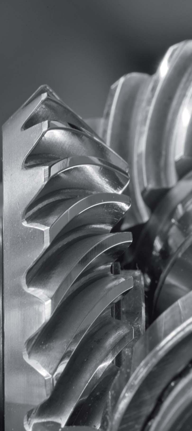
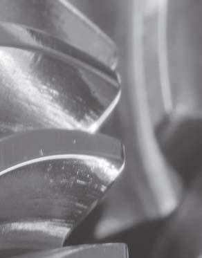
Examples of Applications
 Examples of Applications Optimum positioning of the tooth contact pattern is essential for a precise, low-noise bevel gear pairing. Angular milling head with ground bevel gear set by MS-Graessner. High-transmission
5 Lubrication, Cooling and Heating
 Overview of the and cooling types Lubrication, and Heating.1 Overview of the and cooling types The following combinations of and cooling types are possible. Lubrication Splash with shaft end pump /SEP
KS TWINGEAR. Compact, precise and powerful.
 MS-Graessner GmbH & Co. KG THE GEAR COMPANY Compact, precise and powerful Precision combines with performance. Bevel gear technology is at the heart of an assembly consisting of gear housing, shafts, flanges
8 Design and Operating Notes
 Lubricants Design and Operating Notes.1 Lubricants General information Unless a special arrangement is made, SEW-EURODRIVE supplies the drives with a lubricant fill adapted for the specific gear unit and
X.. Series Helical and Bevel-Helical Gear Units
 SEW-EURODRIVE Easy Guide Industrial Gear Units X.. Series Helical and Bevel-Helical Gear Units Edition 05/2018 24803731/ EN 2/16 Gear unit structure 1 Safety notes 2 Gear unit designs 3 Mounting positions
NMRV - MCV - NRV NMRV+NMRV PC+NMRV
 MAINTENANCE AND OPERATING INSTRUCTIONS FOR WORM GEAR REDUCERS AND GEARMOTORS SERIES: NMRV - MCV - NRV NMRV+NMRV PC+NMRV GB NMRV-UM-9 99/01 rev.15.07.99 2 Warehouse storage When moving the unit, care should
EN Page 1/9 EGT-TD Lubricant approvals latest version:
 EN Page 1/9 Change information: Chap. /page Description (changes to the previous edition) Modification no. General 1.3 / 4 1.4 / 5 1.5 / 6 SEW lubricants added. Lubricant supplier Texaco deleted. Chapter
6 Lubricants. 6 Design and Operating Notes. 6.1 Lubricants. General information
 Lubricants Design and Operating Notes.1 Lubricants General information Unless a special arrangement is made, SEW supplies the drives with a lubricant fill adapted for the specific gear unit and mounting
BA EN.=A. Ä.=A.ä. Operating Instructions. Gearbox. Type 12. / 52.
 BA 12.0028 EN.=A. Ä.=A.ä Operating Instructions Gearbox Type 12. / 52. Product key Gearboxes 1 2... Product group Product family Gearbox size Design Geared motors 1 2... Product group Product family Gearbox
6 Design and operating notes
 Error! B ookmark not d efined.error! Boo kmark not defin ed. Error! B ookmark not d efined.error! Boo kmark not defin ed. and operating notes Lubricants and operating notes.1 Lubricants.1.1 General information
6 Design and Operating Notes
 Design and Operating Notes Lubricants Design and Operating Notes. Lubricants General information Unless a special arrangement is made, SEW-EURODRIVE supplies the drives with a lubricant fill adapted for
Operating and Maintenance Instructions. Abteilung TB, Schell Seite 1 8 SERIES 56
 Abteilung TB, Schell Seite 1 8 These instructions supersede all earlier instructions, in particular BWS 109-0 till BWS 109-3. For applications in areas with explosion hazard it is obligatory to observe
Operating Instruction
 Operating Instruction Drive element LEWA - ecosmart type LCA with manual stroke adjustment, motor mounted vertically Table of contents 1 General information / safety 1.1 Important preliminary information
Approved Suppliers
 EN Page 1/8 Change information: Chap. /page Description (changes to the previous edition) Modification no. Page 7 CLP HC 320 / Mobil SHC Gear 320 / highest oil bath temperature changed from 95 C to 100
LUBRICATION, INSTALLATION, OPERATION & MAINTENANCE INSTRUCTIONS FOR STAINLESS STEEL CONE DRIVE SPEED REDUCERS
 LUBRICATION, INSTALLATION, OPERATION & MAINTENANCE INSTRUCTIONS FOR STAINLESS STEEL CONE DRIVE SPEED REDUCERS Cone Drive double-enveloping worm gear speed reducers are used throughout industry to provide
5 Lubrication, Cooling, and Heating
 Lubrication,, and Heating Overview of the and cooling types Lubrication,, and Heating.1 Overview of the and cooling types The following combinations of and cooling types are possible. Lubrication Splash
MAINTENANCE AND USE INSTRUCTIONS FOR WORM GEAR REDUCERS AND GEARMOTORS SERIES: SW - ISW - SW+SW ISW+SW
 MAINTENANCE AND USE INSTRUCTIONS FOR WORM GEAR REDUCERS AND GEARMOTORS SERIES: SW - ISW - SW+SW ISW+SW GB 2 Warehouse storage When moving the unit, care should be taken to protect external parts from breakage
POWER GEAR The high performance bevel gearbox
 MS-Graessner GmbH & Co. KG THE GEAR COMPANY The high performance bevel gearbox Precision combines with performance. Bevel gear technology is at the heart of an assembly consisting of gear housing, shafts,
Original operation instructions GFC escalator gear units FTSST158.1, FTSST180.1, FTSST212.1
 Translation of the Original operation instructions GFC escalator gear units FTSST158.1, FTSST180.1, FTSST212.1 AUMA Drives GmbH Grenzstraße 5 D-01640 Coswig/ Germany Phone: +49 (0) 3523 94 60 Fax: +49
Installation and Operating Instructions for EAS -NC clutch Type 45_. _. _ Sizes 02 and 03
 Table of contents: Please read and observe this Operating Instruction carefully! A possible malfunction or failure of the clutch and any damage may be caused by not observing it. Page 1: - Table of contents
Operating Instructions. Globoidal cam gear
 Operating Instructions Globoidal cam gear Type : Serial No. : TABLE OF CONTENTS 1. General 1.1 Validity 1.2 Safety instructions 1.3 Shipment 1.4 Transport Regulations 1.5 Weights of gear types 2. Instructions
OIL CAPACITIES FOR SERIES HP APPROXIMATE CAPACITIES IN QUARTS AND GALLONS
 OIL CAPACITIES FOR SERIES HP APPROXIMATE CAPACITIES IN QUARTS AND GALLONS SINGLE REDUCTION REDUCERS - FLOOR MOUNTED POSITION UNIT SIZE 0 5 0 5 0 50 60 80 00 0 WORM OVER GEAR WORM UNDER GEAR VERTICAL OUTPUT
Operating Instructions
 BA 12.0028 450 298 EN Operating Instructions K12.0549 Typ Gearboxes 12.jjj 52.jjj Product key Gearboxes ➀ ➁ ➂ ➃ Product group Product family Gearbox size Design ➀ ➁ ➂ ➃ 12. 602. 20. 11 Geared motors ➀
Certified Quality System UNI EN ISO 9001 : 2008 SERVICE MANUAL PGRF series Release A10/14
 312 Certified Quality System UNI EN ISO 9001 : 2008 www.comerindustries.com SERVICE MANUAL PGRF series Release A10/14 INDEX GENERAL INFORMATION... 3 GEARBOX UNIT IDENTIFICATION... 3 RISKS AND PRECAUTIONS...
FLENDER ZAPEX couplings. Type ZWT. Operating instructions BA 3505 EN 10/2011. FLENDER couplings
 FLENDER ZAPEX couplings Type ZWT Operating instructions FLENDER couplings FLENDER ZAPEX couplings Type ZWT Operating instructions Translation of the original operating instructions Technical data Notes
Original operation instructions Worm gear units S40.1 S450.1
 Translation of the Original operation instructions AUMA Drives GmbH Grenzstraße 5 D-01640 Coswig/ Germany Phone: +49 (0) 3523 94 60 Fax: +49 (0) 3523 74 675 www.auma-drives.com AUMA Drives Service Phone:
Handbuch für installation, betrieb und wartung Planetengetriebe
 Italy Headquarters Installation, use and maintenance manual Manuale Installazione Uso e Manutenzione Riduttori Epicicloidali Installation, Operation and Service Manual Handbuch für installation, betrieb
Operating Instructions. Parallel shaft cam gear
 Operating Instructions Parallel shaft cam gear Type : Serial No. : C O N T E N T S 1. General 1.1 Validity 1.2 Safety instructions 1.3 Shipment 1.4 Transport Regulations 1.5 Weights of gear types 2. Instructions
ATEX g500. Gearboxes B45... B4300 H45... H3000 S S4500. Operating Instructions
 ATEX g500 B45... B4300 H45... H3000 S130... S4500 Gearboxes Operating Instructions EN Ä.X@[ä.X@[ Please read these instructions before you start working! Follow the safety instructions enclosed. 0Abb.
RADEX -N Composite Operating/Assembly instructions
 1 of 14 RADEX -N is a torsionally stiff flexible steel lamina coupling. It is able to compensate for shaft misalignment, for example caused by thermal expansion, etc. note ISO 101. Drawn: 0.05.15 Kb/Wig
PO Box 645, Stockton, Missouri, FAX superiorgearbox.com
 I000-7000-D0447-A 4/7/05 1 SAFETY PRECAUTIONS CAUTION Please read this entire document prior to operating the gear drive. Gear drive failure and / or injury to operators may be caused by improper installation,
XCEL Series of Turbine Mixers
 TABLE OF CONTENTS - TABLE OF CONTENTS Bulletin 01-050 (Recommended bolting torques)..pg.1 Bulletin 02-135 (Installation of Mixer Drive Size 15 to 19)..Pg. 2 Bulletin 04-135 (Maintenance of Mixer Drive
Operating Instructions
 ISO 9001 ISO 9001 Gear Units OIVCE0101/0514 Operating Instructions Contents Contents... 02 1 - How to Use This Manual... 04 2 - Unit Designation... 05 2.1- Detailed Unit Designation... 05 2.2- Nameplate,
6 Design and Operating Notes
 Lubricants and fill quantities GK 0 Design and Operating Notes. Lubricants and fill quantities General information Unless a special arrangement is made, SEW-EURODRIVE supplies the drives with a lubricant
3 Mounting Positions and Important Order Information
 General information on mounting positions M1 Mounting Positions and Important Order Information.1 General information on mounting positions Mounting position designation SEW differentiates between si mounting
Starting up hydraulic systems
 General / Installation A hydraulic system that operates economically, safely, and trouble-free requires careful planning, as well as proper installation and start-up. Conscientious maintenance has a considerable
Addendum to the Assembly and Operating Instructions
 Drive Technology \ Drive Automation \ System Integration \ Services *2100516_017* Addendum to the Assembly and Operating Instructions Industrial Gear Units Motor Pump with Pressure Lubrication /ONP1 Edition
ATEX G.. Ä.TEóä. Gearboxes / geared motors GST, GFL, GKS, GKR, GSS. Operating Instructions. .TEó
 ATEX G.. GST, GFL, GKS, GKR, GSS Gearboxes / geared motors Operating Instructions EN Ä.TEóä.TEó Please read these instructions before you start working! Follow the enclosed safety instructions. 0Abb. 0Tab.
5 Lubricants. Lubricants Guidelines for lubricant selection. 5.1 Guidelines for lubricant selection STOP
 Guidelines for lubricant selection Lubricants. Guidelines for lubricant selection Unless a special arrangement is made, SEW-EURODRIVE delivers the planetary gear unit without an oil fill and the primary
INSTALLATION, OPERATION AND MAINTENANCE INSTRUCTIONS
 INSTALLATION, OPERATION AND MAINTENANCE INSTRUCTIONS Contents Section 1. General Observations... 2 2. Operation... 4 3. Control During Operation... 5 4. Trouble Shooting... 6 5. Maintenance... 7 Please
DOCUMENTATION - INSTALLATION _ MAINTENANCE
 Bevel gears DOKUMENTATION BETRIEBS_ UND WARTUNGSANLEITUNG DOCUMENTATION - INSTALLATION _ MAINTENANCE FOR BEVEL GEARS 1 Bevel gears Radial forces Permissible radial load (stress) on input (d 1 ) and output
Addendum to the Assembly and Operating Instructions
 Drive Technology \ Drive Automation \ System Integration \ Services *205516_017* Addendum to the Assembly and Operating Instructions Industrial Gear Units Motor Pump with Pressure Lubrication /ONP1L Edition
BoWex FLE-PA. BoWex FLE-PAC. KTR-N Sheet: Edition: EN 1 of BoWex FLE-PA / FLE-PAC Operating/Assembly instructions
 1 of 17 is a torsionally rigid flange coupling. It is able to compensate for shaft misalignment, for example caused by manufacturing inaccuracies, thermal expansion, etc. BoWex FLE-PA BoWex FLE-PAC Drawn:
314 ORDINARY MAINTENANCE MANUAL FOR. PGA series VERTICAL MOUNTING POSITION. Release A02/15
 314 www.comerindustries.com ORDINARY MAINTENANCE MANUAL FOR PGA series VERTICAL MOUNTING POSITION Release A02/15 INDEX General information...page 3 Ordinary maintenance...page 4 Oil lubricant replacement...page
Operating Instructions
 Operating Instructions BE2700 Brinkmann Immersions pumps of the series TA/STA/TAL/SAL901... 1303 Contents 1 General...1 2 Safety...2 3 Transport and storage...2 4 Description of product and accessories...2
BA EN.A0= L force Geared Motors. Ä.A0=ä. Operating Instructions GST, GFL, GKS/GKL, GKR, GSS. Gearbox
 BA 12.0023 EN.A0= L force Geared Motors Ä.A0=ä Operating Instructions G GST, GFL, GKS/GKL, GKR, GSS Gearbox Product key Legend for product key Gearbox type GST GFL GKS/GKL GKR GSS Helical gearbox Shaft
Worm Gear Reducers Installation, Lubrication and Maintenance Instructions
 Selection Information Read ALL instructions prior to operating reducer. Injury to personnel or reducer failure may be caused by improper installation, maintenance or operation. Written authorization from
HP High-Performance Gear Units with <2' Adjustable Backlash
 Page HP High-Performance Gear Units with
Installation and Operational Instructions for EAS -Compact overload clutch, Type 49_. 4._ Sizes 4 and 5
 Please read these Operational Instructions carefully and follow them accordingly! Ignoring these Instructions may lead to malfunctions or to clutch failure, resulting in damage to other parts. Contents:
CHO HELICAL-HYPOID GEAR UNITS
 CHO HELICAL-HYPOID GEAR UNITS Kuželočelní převodovky INTRODUCTION CHO helical hypoid gear units have been conceived to be used instead of worm gearboxes where high efficiency is requested, especially with
For advanced drive technology CLAMPEX. Shaft-hub-connection. KTR Precision joints CLAMPEX
 technology CLAMPEX Shaft-hub-connection CLAMPEX KTR Precision joints 227 technology Table of contents Page Brief information 228 Selection and calculation 25-255 CLAMPEX -Selection Shaft diameter = d 0
INTRODUCTION GENERAL GUIDELINES ATTACHING THE DRIVE PARTS
 INTRODUCTION Kretzschmar DC motors are of substantialy designed and manufactured to high standards. These motors will work satisfactorily for many years as long as they are maintained following the instructions.
VEM motors Thurm GmbH
 VEM motors Thurm GmbH Installation, Operating and Maintenance Instructions Single-Phase Squirrel-Cage Induction Motors, Standard Version March 2005 1. General To avoid damage to the motors and equipment
Danfoss Bauer GmbH Esslingen BA GB
 Danfoss Bauer GmbH 73726 Esslingen Operating instructions Direct current permanent magnet geared motors BA 148 04 GB 1 Installation The drive must be assembled and connected by qualified personnel (skilled
6 Design and Operating Notes
 Reduced backlash gear units GSE Design and Operating Notes.1 Reduced backlash gear units Helical, parallel shaft helical and helical-bevel gear units with reduced backlash are available from gear unit
For advanced drive technology CLAMPEX. Shaft-Hub-Connection. KTR Precision Joints CLAMPEX
 technology CLAMPEX Shaft-Hub-Connection CLAMPEX KTR Precision Joints 07 technology Table of contents Page Brief information 09 Selection and calculation -5 CLAMPEX -Selection Shaft diameter = d 0 10 0
FLENDER ARPEX Plate packs with close-fitting bolt connection. ARW-4 Sizes to Assembly instructions An 4239 en 12/2015.
 FLENDER ARPEX Plate packs with close-fitting bolt connection ARW-4 Sizes 101-4 to 292-4 Assembly instructions FLENDER couplings FLENDER ARPEX Plate packs with close-fitting bolt connection ARW-4 Sizes
Operating instruction ATEX. European Directive 2014/34/EU. Spiral bevel gearboxes in explosion proof version
 Operating instruction ATEX European Directive 2014/34/EU Spiral bevel gearboxes in explosion proof version Product Code Spiral Bevel Gearboxes Gearbox type Gearbox size Gear ratio Bottom-facing side Fittings
2000HG R-SERIES IN-LINE HELICAL GEAR REDUCER
 2000HG R-SERIES IN-LINE HELICAL GEAR REDUCER INSTALLATION AND MAINTENANCE MANUAL April 10, 2018 7997 Allison Avenue, Indianapolis, IN 46268 Website: www.sterlingelectric.com (800) 866-7973 FAX (317) 872-0907
Parts made by people who race and know what it is about
 RACING TRANSMISSIONS / 840 SERIES The 840 series has been one of the best options for front engine-rear wheel drive racing cars with4/6 cylinder engines since 1975; formerly, with the TC models, and at
Maintenance Instructions
 General Note These instructions contain information common to more than one model of Bevel Gear Drive. To simplify reading, similar models have been grouped as follows: GROUP 1 Models 11, 0, 1,, (illustrated),,
PO Box 645, Stockton, Missouri, FAX superiorgearbox.com W D0446-A 4/1/05 1
 W000-7000-D0446-A 4/1/05 1 SAFETY PRECAUTIONS CAUTION Please read this entire document prior to operating the gear drive. Gear drive failure and / or injury to operators may be caused by improper installation,
TROUBLESHOOTING SPECIAL TOOL ASSEMBLY AND ADJUSTMENT
 1 INDEX Models FD, FE, FF and SG REAR AXLE 10-1 10-108E-07 CHAPTER 10 REAR AXLE Models FD, FE, FF and SG TROUBLESHOOTING...10-2 10 SPECIAL TOOL...10-3 WHEEL HUB AND RELATED PARTS DISASSEMBLY...10-7 INSPECTION...10-9
ATEX g500. Ä.TF}ä. Gearboxes B45... B450 H45... H450 S S660. Operating Instructions .TF}
 ATEX g500 B45... B450 H45... H450 S130... S660 Gearboxes Operating Instructions EN Ä.TF}ä.TF} Please read these instructions before you start working! Follow the enclosed safety instructions. 0Abb. 0Tab.
Geared motors. G-motion const. G-motion const
 Geared motors G-motion const G-motion const Product code Geared motors Type designation Gearbox Gearbox No. of Input Output Drive size type size stages design design G G G G G S F K K S T L S R S Helical
GENERAL INSTRUCTIONS RETAIN FOR FUTURE USE
 GENERAL INSTRUCTIONS RETAIN FOR FUTURE USE U10000-1 of 2 1. Importance of the operating instructions These operating instructions are intended to provide general information and safety guidelines. It is
Screw Jack M-J / MH-Series Version N/VK/R. Operating Manuel
 Screw Jack M-J / MH-Series Version N/VK/R Operating Manuel 1 Important Information... 2 1.1 Instructions on Documentation...2 1.2 Safekeeping of the Documentation...2 1.3 Used Symbols...2 1.4 Qualified
Edition. Planetary Gear Units P..RF.., P..KF.. Series 12/2002. Operating Instructions X / EN
 Planetary Gear Units P..RF.., P..KF.. Series Edition 12/2002 Operating Instructions 1055 291X / EN SEW-EURODRIVE Contents M1 M6 1 Important Notes... 4 2 Safety Notes... 5 2.1 Extended storage... 7 2.2
Axial Piston Fixed Pump A17FNO Series 10
 Axial Piston Fixed Pump A17FNO Series 10 RE 91510 Issue: 06.2012 Replaces: 03.2010 Size 125 Nominal pressure 250 bar Maximum pressure 300 bar For commercial vehicles Open circuit Features Fixed pump with
DRIVE SHAFT & FRONT AXLE
 DRIVE SHAFT & FRONT AXLE Return To Main Table of Contents GENERAL... 2 DRIVE SHAFT... 6 HUB AND KNUCKLE... 13 FRONT AXLE... 15 GENERAL GENERAL SPECIFICATIONS Drive shaft Joint type Outer Inner Length (Joint
Gearmotors and Gear Reducers
 Gearmotors and Gear Reducers OPERATING INSTRUCTIONS 01 805 52 US GENERAL These operating instructions are intended to help you install and operate the drive. For trouble free service, proper installation
SERIES PC INSTRUCTION AND OPERATION MANUAL
 MEGGA SERIES PC INSTRUCTION AND OPERATION MANUAL Models PCT and PCF Close-coupled and frame-mounted single-stage horizontal end-suction pumps. WARNING: Read this manual before installing or operating this
Pneumatic Axial Fan Type Tech. Doc. No. 802
 Pneumatic Axial Fan Type Tech. Doc. No. 802 Illustration can differ from the original Operation and Maintenance Manual Compiled: 06.08.13 815340300_en_Version_02 Page 1 of 11 ATTENTION!!! This pneumatic
PLS / WPLS / PLV / PLS-HP / PLF-HP PLN / WPLN / WGN / PLFN PSN / PSFN PLE / WPLE / PLFE PLPE / WPLPE / PLHE
 Instruction Manual Standard Planetary Gearbox PLS / WPLS / PLV / PLS-HP / PLF-HP PLN / WPLN / WGN / PLFN PSN / PSFN PLE / WPLE / PLFE PLPE / WPLPE / PLHE GB_ 100225283 / Rev. Stand 004 www.zetek.ru +7(495)
Troubleshooting Power Transmission Couplings
 Troubleshooting Power Transmission Couplings Introduction Power transmission couplings are used to connect two shafts that turn in the same direction on the same centerline. There are three principle types
7 Design and Operating Notes
 Lubricants Design and Operating Notes.1 Lubricants General information Unless a special arrangement is made, SEW-EURODRIVE supplies the drives with a lubricant fill adapted for the specific gear unit and
Geareducer model 2700 and 3000
 USER MANUAL Geareducer model 2700 and 3000 INSTALLATION - OPERATION - MAINTENANCE M02-128C ISSUED 04/2013 READ AND UNDERSTAND THIS MANUAL PRIOR TO OPERATING OR SERVICING THIS PRODUCT. maintenance schedule
Gear Units R..7, F..7, K..7, S..7 Series, Spiroplan W. Edition 04/2000. Operating Instructions / EN
 Gear Units R..7, F..7, K..7, S..7 Series, Spiroplan W Edition 04/2000 07/2002 Operating Instructions 1055 2715 / EN SEW-EURODRIVE Inhaltsverzeichnis 1 Important Notes... 4 2 Safety Notes... 5 3 Gear Unit
SERVO MOTORS BRUSHLESS SERVO MOTORS OPERATING INSTRUCTIONS 2016
 SERVO MOTORS BRUSHLESS SERVO MOTORS OPERATING INSTRUCTIONS 2016 3009/16 en Ed.02.2016 Read these Operating Instructions before performing any transportation, installation, commissioning, maintenance or
Instruction for RBP250-3 and RBP300-3
 Framo Anti-heeling Pump 1275-0029 -401 Rev.C Instruction for RBP250-3 and RBP300-3 2 of 13 CONTENTS Page 1 General description 2 1.1 Technical data 3 2 Operating information 3 2.1 Prior to initial start
Installation and Operational Instructions for EAS -Compact overload clutch Type 49_. 4._ Sizes 01 to 3
 Please read these Operational Instructions carefully and follow them accordingly! Ignoring these Instructions may lead to malfunctions or to clutch failure, resulting in damage to other parts. Contents
T R A N S M I S S I O N S OPERATING AND MAINTENANCE MANUAL FG GEAR UNITS UM03/2012/ENG
 T R A N S M I S S I O N S UM03/20/ENG ZG KG FG SG GEAR UNITS ZG FG KG SG. INFORMATION. General information These Operating manual (OM) is part of the gear unit as supplied, and you must read them before
Bevel gearboxes. Catalogue
 Bevel gearboxes Catalogue INDEX Bevel gearbox description... page 2 Manufacturing features... page 2 Materials and components... page 4 Bevel gearbox selection... page 5 Thermal power limit... page 7
FF 20 DIAPHRAGM PUMP INSTALLATION INSTRUCTIONS
 FF 20 INSTALLATION INSTRUCTIONS DIAPHRAGM PUMP FF 20 DCB-4 FF 20 DC-M Before operating the pump and the accessories, please read the Installation Instructions and safety precautions. Installation Instructions
Installation and Operational Instructions for EAS - HTL housed overload clutch Sizes 01 3 Type 490._24.0
 Please read these Operational Instructions carefully and follow them accordingly! Ignoring these Instructions may lead to malfunctions or to clutch failure, resulting in damage to other parts. Contents:
ROTEX Operating/Assembly instructions Type AFN-SB spec. ROTEX
 0223 EN 1 of 13 Torsionally flexible jaw-type couplings AFN-SB spec. and their combinations for finish bored, pilot bored and unbored couplings 0223 EN 2 of 13 is a torsionally flexible jaw coupling. It
SERIES G3DB/AG3DB ELEVATOR
 TM INSTRUCTIONS AND PARTS LIST SERIES G3DB/AG3DB ELEVATOR WARNING This manual, and GENERAL INSTRUCTIONS MANUAL, CA-1, should be read thoroughly prior to pump installation, operation or maintenance. SRM00059
OPERATING INSTRUCTIONS. E Series Worm Gearboxes OIECE
 OPERATING INSTRUCTIONS Worm Gearboxes OIECE0300-048 Contents Contents... 02 - How To Use This Manual... 04 2- Type Designation... 05 2. Detailed unit designation... 05 2.2 Nameplate unit designation...
Operating Instructions
 ISO 9001 ISO 9001 Gear Units OIDCE0201-0814 Operating Instructions Contents Contents 1 How To Use This Manual... 04 2 Unit Designation... 05 2.1 Detailed unit designation... 05 2.2 Nameplate unit designation...
Parts List Single Reduction Models, Cast Iron Units
 Parts List Single Reduction Models, Cast Iron Units 60 51 51 10 24 11 11 9 24 12 19 17 27 31 8 23 7 14 20 28 26 5 1 2 6 44 60 50 23 7 6 30 27 30 4 3 30 13 29 14 22 18 27 43 48 50 8 15 16 12 25 9 51 51
Operating manual. Custom made gearboxes
 Operating manual Custom made gearboxes DSS-Nr. 100389549 DSS-Rev. 001 Datum 16.01.2018 Contents Contents 1 General information 3 1.1 Using the operating manual 3 1.2 Warnings in this operating manual 4