PO Box 645, Stockton, Missouri, FAX superiorgearbox.com
|
|
|
- Elfrieda Parrish
- 6 years ago
- Views:
Transcription
1 I D0447-A 4/7/05 1
2 SAFETY PRECAUTIONS CAUTION Please read this entire document prior to operating the gear drive. Gear drive failure and / or injury to operators may be caused by improper installation, operation or maintenance. The buyer shall be responsible to: Determine if the gear drive selected is mechanically adequate for the chosen application and to verify that published catalog capacities are not exceeded. Ensure that all connected rotating parts in the system are free from critical torsional or any other type vibration. Eliminate any obstruction to cooling airflow when mounting the gear drive. Also consider any accumulation of external debris which could reduce cooling airflow over the unit during operation. INSTALLATION Gear drives must be mounted on a rigid, structurally sound baseplate. Flatness within in. is recommended. Ensure that gear drive mounting pads rest evenly on the baseplate. The use of shims may be required to avoid housing distortion which could alter the gear mesh or cause premature bearing failure. The gear drive may be driven by direct coupling, flexible coupling, or V-belt drive. Couplers should require only a light force to install. The driveline must be accurately aligned within the equipment manufacturer s requirements to limit operating loads and minimize thrust loads on the gear drive shaft. V-belt drives must be mounted close to the housing to minimize excessive overhung loading which could result in early bearing or shaft failures. Sheaves must fit correctly. At installation, a tight forced fit could move the shaft from its normal position and cause internal damage. A loose fit could induce excessive vibration during operation and cause shaft damage or breakage. WARNING When mounting the gear drive, the buyer is responsible to properly determine the quality or grade of fastener, thread engagement, load carrying capacity and torque requirements. WARNING The buyer is responsible to provide protective shields over all external rotating parts, couplers, or shaft extensions mounted on or with the gear drive. Eye shields and protective clothing must be worn when installing or maintaining the gear drive and operating system. I D0447-A 4/7/05 2
3 Initial operation should be carried out under no-load conditions. Before applying power to the gear drive installation, review the following: Check tightness of mounting bolts. Check for proper oil level in gear drive. Be certain that tools, debris, etc., are clear from rotating parts. Rotate the input shaft by hand. If it does not rotate freely, check for uneven mounting, coupling misalignment, or excessive belt tension. If all tests are satisfactory, make connections to shaft(s), ensure that all safety devices are in place, and begin operation. LUBRICATION All gear drives are factory tested prior to shipment. They include the correct amount of oil unless specified by the customer to be shipped dry. The amount of oil in gear drives varies depending on mounting position. In general, the oil level should, as a minimum, partially cover all bearings when the unit is not running. To determine specific oil quantity and type for each model gear drive, contact Technical Support or refer to the associated Superior Gearbox drawing. CAUTION Prior to operation, make sure the gear drive contains the correct amount of oil. If under-filled or over-filled, damage to the gear drive or injury to personnel may result. Approved Lubricants: For gear drives operating in an ambient temp of 15 to 125 F, and oil temperatures to 200 F, Mobilube EP 85W140 (or equivalent) is recommended. For gear drives requiring start-up in an ambient temp below 15 F or operating continuously above 200 F, Mobilube synthetic SHC 80W140 (or equivalent) is recommended. For low RPM applications, Mobilux EP 0 grease (or equivalent) may be used. CAUTION Do not combine synthetic with non-synthetic oils in the gear drive. I D0447-A 4/7/05 3
4 MAINTENANCE WARNING Disconnect power prior to any maintenance and do not bypass or inactivate any safety or protective device. Lock out and tag the power supply to prevent unexpected application of power. Routinely inspect mounting bolts, couplers, or other power transmitting devices to ensure all parts are firmly anchored. Keep shafts and vent plugs (when included) clean to prevent foreign particles from entering seals or housing. Inspect daily for any oil leaks and any unusual noises. Inspect weekly for end play in shafts. Inspect belt drive tension after the first ten hours of operation and periodically thereafter. Check the oil level every 24 hours of operation. Change the oil when the gear drive has been in service for 50 hours. Routine oil change intervals will vary for each particular installation depending on the severity of the environment. Normal changes should occur between 250 and 1000 hours of operation. The longest life at continuous service will be realized when the oil temperature does not exceed 200 F. For oil substitutions, or for high input speeds, contact Superior Gearbox. WARNING Do not change or add oil while the gear drive is running. Damage to the gear drive or injury to personnel may result. The gear drive housing, oil, plugs, and associated components may reach high temperatures and cause severe burns. Use extreme care when servicing the gear drive. LONG TERM STORAGE or INACTIVITY When a gear drive is stored, prior to initial installation, or following removal from service, the following steps are recommended: Fill completely with oil. Attach a prominent notice that the gear drive must be drained and refilled to the proper level prior to start-up. Apply a rust preventive to the externally exposed shafts. Store the gear drive in a temperature and humidity controlled area. Periodically, rotate the input shaft by hand. If the gear drive is in service but inactive for 60 days or more, periodically rotate the input shaft by hand and check the oil level prior to start-up. I D0447-A 4/7/05 4
5 GEAR DRIVE DISASSEMBLY Gear drive disassembly should be accomplished in a clean, dry, and well lighted area. For a general representation of gear drive parts, see the generic gear drive illustrations on pages 7 and 8. For specific model or assembly information, contact Superior Gearbox. WARNING During operation, the gear drive housing, plugs, and oil may reach high temperatures. To avoid severe burns after removing from operation, allow sufficient time for the gear drive to cool to ambient prior to disassembly. 1. Drain oil by removing a bottom drain plug (refer to the assembly drawing). If the unit is filled with grease, proceed to step Remove all hex bolts from the housing cover and from the two input caps or from one input cap and a hydraulic adapter. 3. Remove the housing cover carefully to prevent damage to the cover gasket. 4. Remove the worm wheel, bearings, and output shaft (if solid shaft unit) as an assembly. If the bearings will be replaced, note the location and number of any shims used. These should be reinstalled in the same sequence when the unit is reassembled. Press out the oil seals in both the housing and cover and discard. 5. Remove the two input caps or input cap and hydraulic adapter. Note the location and number of any shims used. These should be installed in the same sequence when the unit is reassembled. 6. Using a small arbor press or a rubber mallet, drive out the input shaft / worm gear and bearings. Press out any oil seals remaining in the housing and discard. 7. If the bearings must be replaced, use extreme care to prevent any damage to the seal areas when using press equipment during removal and re-installation. The seal surface finish must be 8 to 25 micro-inch. Both the bearing and seal areas should be polished after bearing removal, however, do not reduce their diameters by excessive polishing or burnishing. 8. If gear replacement is required, use extreme care during removal and replacement of any keys to prevent damage to the shaft seal area. (Note: Only the I210 series uses a keyed input worm gear). I D0447-A 4/7/05 5
6 GEAR DRIVE REASSEMBLY CAUTION The reassembly area should be clean, dry, well lighted and free from oil, grease, or any debris which could contaminate the gear drive oil, bearings or seals. 1. Prior to assembly, all mating surfaces of the unit must be clean and free from oil or debris. 2. SOLID SHAFT UNIT (See page 7): Install key and retaining ring onto output shaft. Insert shaft into gear wheel from rear (wheel cover) side until retaining ring seats into hub recess. Re-install the same number, and in the same sequence, any shims removed during the disassembly process. Press the inner bearing cones onto both sides of shaft until seated onto gear wheel or shims. HOLLOW BORE UNIT (See page 8): Re-install onto the worm wheel the same number, and in the same sequence, any shims removed during the disassembly process. Press the inner bearing cones onto both sides of the worm wheel until seated onto hub or shims. 3. Press the outer bearing cups into the housing and wheel cover. 4. Install the gear wheel into the housing and bolt on cover (use only 4 alternating bolts). 5. CHECK OUTPUT ROLLING TORQUE Rolling torque shall fall within 5 to 25 in-lbs. If not within limits, contact Technical Support at Superior Gearbox. 6. Remove cover and worm wheel from housing. 7. Install keyed worm gear onto input shaft (I210 series only). Press inner bearing cones onto shaft. Insert shaft / gear assembly into housing. 8. Install outer bearing cups into both ends of housing. Re-install the same number, and in the same sequence, any shims removed during the disassembly process. Install seals into end caps. Install end caps (with gaskets) onto housing. Note that shims are positioned between bearing cup and nose of end cap. Ensure that seals are not damaged by shaft during installation. Tighten end cap bolts alternately, such that the outer bearing cups are moved into proper position in housing. 9. Re-install worm wheel, meshing gear teeth with worm. Bolt on cover (4 alternating bolts). 10. CHECK INPUT ROLLING TORQUE Check rolling torque thru the input, which shall fall within 5 to 15 in-lbs. If not within limits, contact Technical Support at Superior Gearbox. 11. SET GEAR MESH Remove wheel cover and gear wheel. Coat gear wheel teeth with lithium base grease (white or yellow). Re-install into housing with cover. Rotate input shaft to complete one revolution of gear wheel. Remove wheel cover and gear wheel. Check mesh pattern on wheel teeth. Gear teeth should mesh on the centerline of gear wheel within ±.03. If not on centerline, contact Technical Support at Superior Gearbox. 12. Reassemble. Torque 5/16-18 screws to ft-lbs. Fill with the proper amount of oil through the oil fill hole. Replace the fill plug. This completes the reassembly. I D0447-A 4/7/05 6
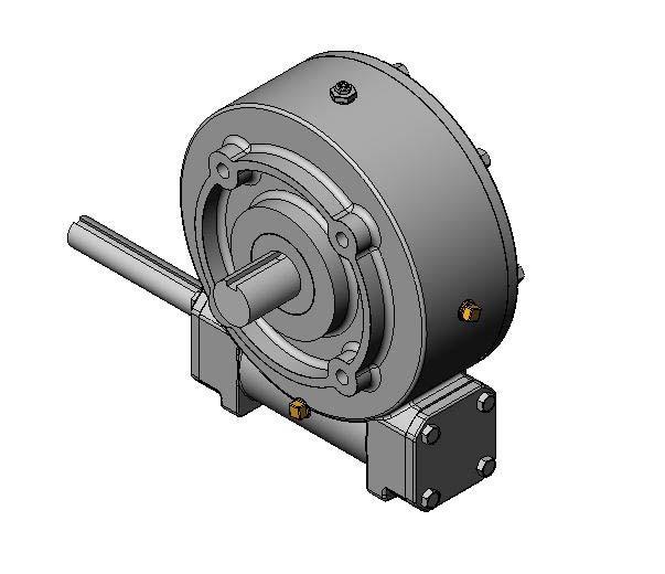
7 GENERIC WORM GEAR DRIVE ILLUSTRATION SOLID SHAFT UNIT I D0447-A 4/7/05 7


8 GENERIC WORM GEAR DRIVE ILLUSTRATION HOLLOW BORE UNIT I D0447-A 4/7/05 8
 UNTIL IT PROTRUDES FROM FROM FAR")


9 INSTALLATION OF OUTPUT SHAFT INTO HOLLOW BORE WORM DRIVE 1. PUSH SHAFT (IN DIRECTION OF ARROW) UNTIL IT PROTRUDES FROM FROM FAR SIDE 2. INSTALL KEY INTO SHAFT 3. INSTALL EXTERNAL RETAINING RING INTO GROOVE ON END OF SHAFT 4. PULL SHAFT BACK THRU HOLLOW BORE UNTIL RETAINING RING SEATS AGAINST INTERNAL SHOULDER 5. INSTALL INTERNAL RETAINING RING INTO GROOVE OF HOLLOW BORE. THIS WILL TRAP THE SHAFT RETAINING RING BETWEEN THE HOLLOW BORE SHOULDER AND THE INTERNAL RETAINING RING 6. PRESS THE END CAP INTO THE WORM DRIVE COVER I D0447-A 4/7/05 9
10 TROUBLESHOOTING SYMPTOM PROBABLE CAUSE REMEDY Breather leaking Incorrect oil level Check oil level RPM too high Reduce RPM Unit running hot Provide additional cooling Unit running hot Incorrect oil level Check oil level Inadequate air flow Provide additional cooling Excessive RPM or load Change to synthetic oil Contaminated oil Replace oil Failing bearings Replace bearings Unusual noise Gear mesh changed Inspect driveline Excessive external load Inspect belt tension Failing bearings or gears Replace bearings or gears Oil leaking Failing seals Replace seals Mating surfaces Rebuild gear drive Vibration Loose mounting bolts Inspect / tighten Loose couplers, pulleys Inspect / tighten Failing bearings or gears Replace bearings or gears Driveline misalignment Correct misalignment I D0447-A 4/7/05 10
PO Box 645, Stockton, Missouri, FAX superiorgearbox.com W D0446-A 4/1/05 1
 W000-7000-D0446-A 4/1/05 1 SAFETY PRECAUTIONS CAUTION Please read this entire document prior to operating the gear drive. Gear drive failure and / or injury to operators may be caused by improper installation,
Maintenance Instructions
 General Note These instructions contain information common to more than one model of Bevel Gear Drive. To simplify reading, similar models have been grouped as follows: GROUP 1 Models 11, 0, 1,, (illustrated),,
Worm Gear Reducers Installation, Lubrication and Maintenance Instructions
 Selection Information Read ALL instructions prior to operating reducer. Injury to personnel or reducer failure may be caused by improper installation, maintenance or operation. Written authorization from
LUBRICATION, INSTALLATION, OPERATION & MAINTENANCE INSTRUCTIONS FOR STAINLESS STEEL CONE DRIVE SPEED REDUCERS
 LUBRICATION, INSTALLATION, OPERATION & MAINTENANCE INSTRUCTIONS FOR STAINLESS STEEL CONE DRIVE SPEED REDUCERS Cone Drive double-enveloping worm gear speed reducers are used throughout industry to provide
Ironman e Series Installation, Lubrication and Maintenance Instructions
 Ironman e Series Installation, Lubrication and Maintenance Instructions Important Selection Information Read ALL instructions and safety precautions prior to operating unit. Injury to personnel or unit
Ironman E Series Installation, Lubrication and Maintenance Instructions
 Ironman E Series Installation, Lubrication and Maintenance Instructions A Regal Brand Important Selection Information Read ALL instructions and safety precautions prior to operating unit. Injury to personnel
Service Manual. Example Part Number. Motor Supplier. Motor Number. Model. Bail Boss. Ratio. Shaft
 Service Manual 50 Series Digger models Example Part Number 50 05 f 54 Model Ratio Shaft Bail Boss Motor Supplier Motor Number This service manual is effective: S/N: 58670 to current date: 9-003 to CURRENT
SERIES G3DB/AG3DB ELEVATOR
 TM INSTRUCTIONS AND PARTS LIST SERIES G3DB/AG3DB ELEVATOR WARNING This manual, and GENERAL INSTRUCTIONS MANUAL, CA-1, should be read thoroughly prior to pump installation, operation or maintenance. SRM00059
Gear Products Inc N. 161st E. Ave. Tulsa, OK Phone (918) Fax (918)
 Fax (918)") SERVICE MANUAL Disassembly & Assembly Procedures Worm Gear Swing Drive 003 Series Gear Products Inc. 1111 N. 161st E. Ave. Tulsa, OK 74116 Phone (918) 234-3044 Fax (918) 234-3455 Worm Gear Swing Drive
SERVICE MANUAL Disassembly & Assembly Procedures Worm Gear Swing Drive 003 Series Gear Products Inc. 1111 N. 161st E. Ave. Tulsa, OK 74116 Phone (918) 234-3044 Fax (918) 234-3455 Worm Gear Swing Drive
Parts List Single Reduction Models, Cast Iron Units
 Parts List Single Reduction Models, Cast Iron Units 60 51 51 10 24 11 11 9 24 12 19 17 27 31 8 23 7 14 20 28 26 5 1 2 6 44 60 50 23 7 6 30 27 30 4 3 30 13 29 14 22 18 27 43 48 50 8 15 16 12 25 9 51 51
OIL CAPACITIES FOR SERIES HP APPROXIMATE CAPACITIES IN QUARTS AND GALLONS
 OIL CAPACITIES FOR SERIES HP APPROXIMATE CAPACITIES IN QUARTS AND GALLONS SINGLE REDUCTION REDUCERS - FLOOR MOUNTED POSITION UNIT SIZE 0 5 0 5 0 50 60 80 00 0 WORM OVER GEAR WORM UNDER GEAR VERTICAL OUTPUT
SERVICE MANUAL 375 SERIES DIGGER MODELS
 SERVICE MANUAL 75 SERIES DIGGER MODELS Example Part Number 75 F 0 BP Model Ratio Shaft Bail Boss Motor Supplier Motor Number Back Spin Protection THIS SERVICE MANUAL IS EFFECTIVE: S/N: 00 TO CURRENT DATE:
Service Manual. Example Part Number. Motor Supplier. Motor Number. Ratio. Bail Boss. Input. Model. Shaft. Cover
 Service Manual 0 Series Digger models Example Part Number 0 7 f 0 C 7 Model Ratio Shaft Bail Boss Motor Supplier Motor Number Cover Input This service manual is effective: S/N: 0000 to current date: 0
2000HB K-SERIES HELICAL BEVEL GEAR REDUCER
 2000HB K-SERIES HELICAL BEVEL GEAR REDUCER INSTALLATION AND MAINTENANCE MANUAL January 22, 2018 7997 Allison Avenue, Indianapolis, IN 46268 Website: www.sterlingelectric.com (800) 866-7973 FAX (317) 872-0907
2000HG NEW STYLE HELICAL GEAR RATIO MULTIPLIER. INSTALLATION AND MAINTENANCE MANUAL May 4, Indianapolis, Indiana (800)
") 2000HG NEW STYLE HELICAL GEAR RATIO MULTIPLIER INSTALLATION AND MAINTENANCE MANUAL May 4, 2017 Indianapolis, Indiana (800) 866-7973 e-mail: sales@sterlingelectric.com www.sterlingelectric.com 7997 Allison
2000HG NEW STYLE HELICAL GEAR RATIO MULTIPLIER INSTALLATION AND MAINTENANCE MANUAL May 4, 2017 Indianapolis, Indiana (800) 866-7973 e-mail: sales@sterlingelectric.com www.sterlingelectric.com 7997 Allison
INSTALLATION, OPERATION, AND MAINTENANCE MANUAL RBK FRP FAN
 Bulletin 62-January-20-09 ROOF UPBLAST & SIDEWALL CENTRIFUGAL FIBERGLASS EXHAUST FAN INSTALLATION, OPERATION, AND MAINTENANCE MANUAL RBK FRP FAN The M.K. Plastics catalog on the above corrosion resistant
Amerigear SF Spindle
 Amerigear SF Spindle Installation and Maintenance Manual Form No. 381-SH, 4/01 Spindle Installation and Maintenance Manual TABLE OF CONTENTS SECTION TITLE PAGE 1 Introduction...: 3 2 General Information...:
Installation,Operation, and Lubrication Instructions SPEED REDUCERS ILDE-00 TYPE DE ENGINEERING SERVICE BULLETIN
 ENGINEERING SERVICE BULLETIN ILDE-00 D-90 TYPE DE SPEED REDUCERS Installation,Operation, and Lubrication Instructions This Engineering Service Bulletin is designed to enable users to obtain the best possible
Installation, Lubrication and. Maintenance. Instructions CONGRATULATIONS!
 Helical InlineDrs,7-07 8/2/07 11:50 AM Page 1 Installation, Lubrication and Maintenance Instructions CONGRATULATIONS! Your decision to purchase a world class reducer from Grove Gear will provide you with
BALDOR IN-LINE HELICAL REDUCER
 BALDOR IN-LINE HELICAL REDUCER s 38 thru 88 These instructions should be read thoroughly before installation or operation. WARNING: High voltage and rotating parts can cause serious or fatal injury and
Geareducer model 2700 and 3000
 USER MANUAL Geareducer model 2700 and 3000 INSTALLATION - OPERATION - MAINTENANCE M02-128C ISSUED 04/2013 READ AND UNDERSTAND THIS MANUAL PRIOR TO OPERATING OR SERVICING THIS PRODUCT. maintenance schedule
SERIES PC INSTRUCTION AND OPERATION MANUAL
 MEGGA SERIES PC INSTRUCTION AND OPERATION MANUAL Models PCT and PCF Close-coupled and frame-mounted single-stage horizontal end-suction pumps. WARNING: Read this manual before installing or operating this
RUFNEK 80 DESIGN SERIES 001 SERVICE MANUAL INTRODUCTION AND THEORY OF OPERATION...2 ASSEMBLY NUMBER EXPLANATION...2 WINCH MODEL CODES...
 RUFNEK 80 DESIGN SERIES 001 SERVICE MANUAL INTRODUCTION AND THEORY OF OPERATION...2 ASSEMBLY NUMBER EXPLANATION...2 WINCH MODEL CODES...2!WARNING!...3 MAINTENANCE...4 GENERAL DISASSEMBLY...5 A. MOTOR DISASSEMBLY...5
2000RA SMOOTH BODY WORM GEAR REDUCER. INSTALLATION AND MAINTENANCE MANUAL June 26, Indianapolis, Indiana (800)
") 2000RA SMOOTH BODY WORM GEAR REDUCER INSTALLATION AND MAINTENANCE MANUAL June 26, 2017 Indianapolis, Indiana (800) 866-7973 e-mail: sales@sterlingelectric.com www.sterlingelectric.com 7997 Allison Avenue,
2000RA SMOOTH BODY WORM GEAR REDUCER INSTALLATION AND MAINTENANCE MANUAL June 26, 2017 Indianapolis, Indiana (800) 866-7973 e-mail: sales@sterlingelectric.com www.sterlingelectric.com 7997 Allison Avenue,
Installation, Operating and Maintenance Instructions. Rotating Machine Screw Actuators. With Parts List Publication Part No.
 Installation, Operating and Maintenance Instructions With Parts List Publication Part No. SK-2389-R1 Rotating Machine Screw Actuators 1/4 Through 1-Ton Capacity Caution This manual contains important information
Amerigear SL Spindle
 Amerigear SL Spindle Installation and Maintenance Manual Form No. 378-SH, 6/97 Spindle Installation and Maintenance Manual TABLE OF CONTENTS SECTION TITLE PAGE 1 Introduction...: 3 2 General Information...:
Housing (Front) - Remove
 - Remove") SENR9978-01 63 1. Lift the assembly (3) of the idler gear and the hub over the housing for the crankshaft front seal (2) and insert the hub into the recess in the cylinder block. Refer to illustration
SENR9978-01 63 1. Lift the assembly (3) of the idler gear and the hub over the housing for the crankshaft front seal (2) and insert the hub into the recess in the cylinder block. Refer to illustration
Geareducer models 1800 and 2000
 USER MANUAL Geareducer models 1800 and 2000 INSTALLATION - OPERATION - MAINTENANCE M00-1218C ISSUED 08/2015 READ AND UNDERSTAND THIS MANUAL PRIOR TO OPERATING OR SERVICING THIS PRODUCT. operation and
Amarillo PUMP DRIVES (250 HP THROUGH 350 HP) INSTRUCTIONS FOR REPAIRING MODELS 250, 300, and 350
 INSTRUCTIONS FOR REPAIRING MODELS 250, 300, and 350") Amarillo PUMP DRIVES (250 HP THROUGH 350 HP) INSTRUCTIONS FOR REPAIRING MODELS 250, 300, and 350 Amarillo Right Angle Pump Drives, if properly installed and maintained, should provide years of service
Amarillo PUMP DRIVES (250 HP THROUGH 350 HP) INSTRUCTIONS FOR REPAIRING MODELS 250, 300, and 350 Amarillo Right Angle Pump Drives, if properly installed and maintained, should provide years of service
DT Small Mixers Installation, Operation, Maintenance Manual
 Manual 272.01 DT Small Mixers Installation, Operation, Maintenance Manual Equipment Reference: 60DTA, 60DTL Style Mixer TABLE OF CONTENTS Initial Inspection 1 Chemineer Assistance 1 Storage 2 Mounting
Instruction Manual For DODGE. Airport Baggage Handling Systems Speed Reducers
 Instruction Manual For DODGE Airport Baggage Handling Systems Speed Reducers ABHS TXT109 - TXT115 - TXT125 ABHS TXT209 - TXT215 - TXT225 ABHS TXT309A - TXT315A - TXT325A ABHS TXT409A - TXT415A - TXT425A
Kysor Rear Air Fan Drives
 On/Off Technology for Heavy-Duty Truck Applications Installation & Service Guide Kysor Rear Air Fan Drives thermal.borgwarner.com For Additional BorgWarner Thermal Systems Information: 800-927-7811 USA
2000HG R-SERIES IN-LINE HELICAL GEAR REDUCER
 2000HG R-SERIES IN-LINE HELICAL GEAR REDUCER INSTALLATION AND MAINTENANCE MANUAL April 10, 2018 7997 Allison Avenue, Indianapolis, IN 46268 Website: www.sterlingelectric.com (800) 866-7973 FAX (317) 872-0907
DeZURIK R1 AND R2 POWERRAC ACTUATORS
 R1 AND R2 POWERRAC ACTUATORS Instruction D10268 July 2016 Instructions These instructions provide installation, operation, and maintenance information for R1 AND R2 POWERRAC Actuators. They include procedures
Kysor On/Off Rear Air Fan Drive
 . Proper precautions must be taken to prevent personal injury from contact with moving parts, unintended engine start, or other hazards present when working with powered equipment. Refer to the vehicle
4.2 WATER PUMP (GEAR CASE MOUNTED AND LATER) (GCM)
 (GCM)") SERIES 60 SERVICE MANUAL 4.2 WATER PUMP (GEAR CASE MOUNTED - 1991 AND LATER) (GCM) The centrifugal-type water pump circulates the engine coolant through the cooling system. The pump is mounted on the rear
SERIES 60 SERVICE MANUAL 4.2 WATER PUMP (GEAR CASE MOUNTED - 1991 AND LATER) (GCM) The centrifugal-type water pump circulates the engine coolant through the cooling system. The pump is mounted on the rear
SECTION steering mechanism
 07-302.01/ 1 2011MR17 SECTION 07-302.01 GENERAL Description See Figure 1. The includes the steering wheel (1), the steering column, the miter box (3), the steering shafts (2 and 4), and the drag link (7).
Geareducer. Repair Manual. Series 27A Series 27T Series 27.1 RM-27D. Manual A
 Geareducer Repair Manual Series 27A Series 27T Series 27.1 RM-27D Manual 92-1412A General Geareducers can be repaired in the field; however, major repairs require the use of a fully equipped machine shop.
Full View Flow Indicator
 Full View Flow Indicator Threaded and Flanged Process Connection Installation / Operation / Maintenance Manual P.O. Box 1116 Twinsburg, OH 44087 Phone: 330/405-3040 Fax: 330/405-3070 E-mail: view@ljstar.com
DelTorq Series 21 ACTUATOR
 Jamieson Equipment Company DelTorq Series 21 ACTUATOR INSTALLATION, OPERATION AND MAINTENANCE MANUAL ENGINEERING DATA SHEET E.D.S. NO EDS055 ISSUE DATE - -- 20/01/2007 (Please read the entire instructions
IOM Manual. IOM Manual. Series 20/21.
 IOM Manual IOM Manual Series 20/21 www.flowlinevalves.com Flow Line Valve and Controls, L.L.C. 110 Main Project Road Schriever, LA 70395 P.O. Box 677 Schriever, LA 70395 Phone 985-414-6004 * Toll Free
NSGV Direct Drive Pressure Blower (AF) Aluminum Housing & Wheel
 Aluminum Housing & Wheel") NSGV SERIES AF PRESSURE BLOWER I, O & M MANUAL NSGV Direct Drive Pressure Blower (AF) Aluminum Housing & Wheel RECEIVING AND INSPECTION All shipments are F.O.B. factory, Decatur, Illinois. It is, therefore,
NSGV SERIES AF PRESSURE BLOWER I, O & M MANUAL NSGV Direct Drive Pressure Blower (AF) Aluminum Housing & Wheel RECEIVING AND INSPECTION All shipments are F.O.B. factory, Decatur, Illinois. It is, therefore,
DelTech Controls L.L.C.
 DelTech Controls L.L.C. DelTorq Series 20 ACTUATORS TECHNICAL DATA SHEET T.D.S. NO. 20 105 / R1 ISSUE DATE : NOV 2004 INSTALLATION, OPERATION AND MAINTENANCE MANUAL Guarantee : ( Please read the entire
INSTALLATION, OPERATION, AND MAINTENANCE MANUAL CNW DHK PVK
 FRP Centrifugal & Inline Fans Bulletin 90-01- NOV2002 INSTALLATION, OPERATION, AND MAINTENANCE MANUAL This publication contains the installation, operation and maintenance instructions for the following
BDU-10/21 Hydrostatic Transmissions Service and Repair Manual
 Hydrostatic Transmissions Service and Repair Manual BLN-50327 January 2018 Table of Contents Table of Contents Description Page Introduction... 3 General Description... 3-5 Fluids... 6 Safety Precautions...
INSTALLATION AND OPERATION
 WARNING: Because of the possible danger to persons(s) or property from accidents which may result from the improper use of products, it is important that correct procedures be followed. Products must be
SERVICE MANUAL GENERAL ASSEMBLY...14
 DESIGN SERIES 006 RUFNEK 80 SERVICE MANUAL INTRODUCTION AND THEORY OF OPERATION...2 ASSEMBLY NUMBER EXPLANATION... 2 WINCH MODEL CODES... 2 MAINTENANCE... 5 GENERAL DISASSEMBLY...6 A. MOTOR DISASSEMBLY...6
 Page 1 of 15 Transmission, Model S5-42 ZF Model S5-42 ZF Disassembly NOTE: For 4x4 and F-Super Duty vehicles, skip to Step 5. 1. Attach the transmission to the Bench Mounted Holding Fixture T57L-500-B
INSTALLATION, OPERATION, MAINTENANCE MANUAL FOR MANUALLY OPERATED STOP CHECK VALVE
 INSTALLATION, OPERATION, MAINTENANCE MANUAL FOR MANUALLY OPERATED STOP CHECK VALVE Page 1 of 13 1.1 General CHAPTER 1 - GENERAL INFORMATION This manual contains maintenance instructions with pertinent
JT Series Miter Gearbox
 JT Series Miter Gearbox 1 Contents General information ---------------------------------------------------------------------------- 3 Configurations -----------------------------------------------------------------------------------
INSTRUCTION MANUAL AND PARTS LIST FOR PG/RG3D_-187, 218, 250 and 312 SERIES PUMPS
 INSTRUCTION MANUAL AND PARTS LIST FOR PG/RG3D_-187, 218, 250 and 312 SERIES PUMPS WARNING This Instruction Manual and General Instructions Manual, CA-1, should be read thoroughly prior to pump installation,
Geareducer models
 USER MANUAL Geareducer models 2200-2250-2400 OPERATION - MAINTENANCE - REPAIR M99-1260E ISSUED 6/2012 READ AND UNDERSTAND THIS MANUAL PRIOR TO OPERATING OR SERVICING THIS PRODUCT. operation and service
Flow Line Controls. Installation & Operations Manual SERIES 20/21 Pneumatic Actuators
 Flow Line Controls Installation & Operations Manual SERIES 20/21 Pneumatic Actuators Flow Line Controls, Inc. P.O. Box 677 Schriever, LA 70395 Phone: 985-414-6003 Toll Free 1-800-815-9226 Fax 985-414-6072
NOTE: Visit our website at for video repair procedures, under the Tools section.
 Repair Instructions Hypro Repair Tools: Tool Box No. 3010-0168 1/4" Allen Wrench No. 3020-0008 Support Bars (2) No. 3010-0064 Port Brush No. 3010-0066 1/16" Allen Wrench No. 3020-0009 Brush Holder No.
Valtek Auxiliary Handwheels and Limit Stops
 Valtek Auxiliary s and Limit Stops Table of Contents Page 1 General information 2 Installation 2 Side-mounted handwheels, size 25 and 50 (linear actuators) 3 Side-mounted handwheels, size 100 and 200 (linear
RUFNEK 45 SERVICE MANUAL
 DESIGN SERIES 003 RUFNEK 45 SERVICE MANUAL INTRODUCTION AND THEORY OF OPERATION...2 ASSEMBLY NUMBER EXPLANATION...2 WINCH MODEL CODES...2!WARNING!...3 MAINTENANCE...5 GENERAL DISASSEMBLY...6 A. MOTOR DISASSEMBLY...7
Installation and Parts Replacement Manual for DODGE Double Reduction Screw Conveyor and Hydroil Screw Conveyor Drive
 Installation and Parts Replacement Manual for DODGE Double Reduction Screw Conveyor and Hydroil Screw Conveyor Drive SCXT / HSCXT 1A SCXT / HSCXT 5C SCXT / HSCXT 2A SCXT / HSCXT 3B SCXT / HSCXT 4B SCXT
Model QED-D, QED-A, QED-L
 This supplement is for Field Service use only, as complete dis-assembly and re-assembly of the QED reducer by the customer is NOT recommended. This supplement only extends to single reduction QED units.
tRIPr Chief Grain Cart. Operator s Manual. Operator s Manual
 125-000-01 125-000-01 1tRIPr 1tRIPr Operator s Manual 1210 Chief Grain Cart Operator s Manual Operator s Manual TO THE DEALER Predelivery/Delivery Checklist 1210 Grain Cart PREDELIVERY/DELIVERY CHECKLIST
Binks MODELS & AGITATOR DRIVE UNITS
 Binks MODELS 31-393 & 31-394 AGITATOR DRIVE UNITS for Agitator Equipped Drum MODEL 31-393 Includes the following items: 1, 2, and 3. 1 MODEL 31-394 shown. 17 4 3 2 12 13 14 15 2 3 8 5 9 11 8 10 6 7 17
OVERLOAD CLUTCHES FOR INDEX DRIVES
 The Driving Force in Automation OVERLOAD CLUTCHES FOR INDEX DRIVES WARNING WARNING This is a controlled document. It is your responsibility to deliver this information to the end user of the CAMCO indexer.
/ Marley Geareducer Model 3600 and 4000 / User Manual C
 / Marley Geareducer Model 3600 and 4000 / User Manual 00-198C / Operation and Service Instructions / Protection Against Corrosion As shipped, a Marley Geareducer is protected internally against corrosion
I N S TA L L AT I O N G U I D E
 INSTALLATION GUIDE TM Installation Guide Contents Page Open Differential Part Identification & Terminology... 2 Powertrax No-Slip Differential Exploded View... 3 Vehicle Preparation for Installation (steps
Advanced Technology Tension Clutches
 P-220 819-0339 Advanced Technology Tension Clutches Installation Instructions Contents Installation................................. 2 Clutch Repair On the Shaft.................. 4 Clutch Service Major.......................
Maintenance Information
 16573370 Edition 2 February 2014 Air Grinder 99V Series Maintenance Information Save These Instructions Product Safety Information WARNING Failure to observe the following warnings, and to avoid these
RUFNEK 100 SERVICE MANUAL
 DESIGN SERIES 004 RUFNEK 100 SERVICE MANUAL INTRODUCTION AND THEORY OF OPERATION...2 ASSEMBLY NUMBER EXPLANATION...2 WINCH MODEL CODE...2 MAINTENANCE...5 GENERAL DISASSEMBLY...6 A. MOTOR DISASSEMBLY...6
Through-Shaft Clutch-Brake LSCB-32HT, LSCB-32HT, LSCB-44, LSCB-44HT, LSCB-54HT FORM NO. L D-0606 MEX (55) QRO (442)
 QRO (442)") Through-Shaft Clutch-Brake LSCB-HT, LSCB-HT, LSCB-, LSCB-HT, LSCB-5HT In accordance with Nexen s established policy of constant product improvement, the specifications contained in this manual are subject
Through-Shaft Clutch-Brake LSCB-HT, LSCB-HT, LSCB-, LSCB-HT, LSCB-5HT In accordance with Nexen s established policy of constant product improvement, the specifications contained in this manual are subject
REDUCER LUBRICATION HORIZONAL APPLICATIONS VERTICAL MOUNT REDUCER INSTALLATION CHAR-LYNN H, S, T AND 2000 SERIES 6B SPLINE MOTOR INSTALLATION
 Parts Replacement Manual For HYDROIL TORQUE-ARM Speed Reducers Taper Bushed For Char-Lynn * H, S, T and 000 Series B Spline Motors SIZES: HXT0A, HXTA, HXT0A These instructions must be read thoroughly before
SERVICE MANUAL L130B / L4130 Series Logstacker Drive Axle With Bolt-On Stub End Retainer
 SERVICE MANUAL L130B / L4130 Series Logstacker Drive Axle With Bolt-On Stub End Retainer Page 1 Allied Form #80-930 Rev 07/2009 SERVICE MANUAL LOG STACKER DA202 DRIVE AXLE TABLE OF CONTENTS PROCEDURE FOR
I N S TA L L AT I O N G U I D E
 INSTALLATION GUIDE TM Installation Guide Contents Page Open Differential Part Identification & Terminology... 2 Powertrax No-Slip Differential Exploded View... 3 Vehicle Preparation for Installation (steps
Figure 1 - Assembly. Note: A Screw Conveyor Drive consists of two sub-assemblies and a drive shaft all listed below.
 Instruction Manual For Dodge 6B Hydroil Screw Conveyor Drive HSCXT3A 6B thru HSCXT7 6B Double Reduction Hydroil Screw Conveyor Drive for Char-Lynn H, S, T and 000 Series 6B Spline Motors These instructions
AIR CLEANERS Model MC 3000 OWNER S MANUAL CAUTION Read complete instructions before operating. Please file for future reference.
 AIR CLEANERS Model MC 3000 OWNER S MANUAL CAUTION Read complete instructions before operating. Please file for future reference. MODEL MC 3000 SPECIFICATION Input Volts: 208-230/430 VAC, 60Hz, 3 Phase
FHB 8110 Brake Assemblies Installation, Operation and Maintenance Manual Airflex
 FHB 8110 Brake Assemblies Installation, Operation and Maintenance Manual Airflex General Information Forward this manual to the person responsible for Installation, Operation and Maintenance of the product
TL (TIL03029) REPAIR MANUAL. Telma model FN72-40 replacement on Arvin Meritor forward tandem carrier. Page 1 of JUL-11.
 REPAIR MANUAL. Telma model FN72-40 replacement on Arvin Meritor forward tandem carrier. Page 1 of JUL-11.") REPAIR MANUAL Telma model FN72-40 replacement on Arvin Meritor forward tandem carrier Page 1 of 10 29-JUL-11 Exploded view P/N: FE962100 Stator Carrier Kit Includes: Qty Description Telma P/N 1 Stator
REPAIR MANUAL Telma model FN72-40 replacement on Arvin Meritor forward tandem carrier Page 1 of 10 29-JUL-11 Exploded view P/N: FE962100 Stator Carrier Kit Includes: Qty Description Telma P/N 1 Stator
INSTALLATION AND MAINTENANCE MANUAL
 TYPE 2 PTO INSTALLATION AND MAINTENANCE MANUAL P.O. Box 8148 Wichita Falls, Texas 76307 1600 Fisher Rd. Wichita Falls, Texas 76305 Phone: (940) 7611971 Fax: (940) 7611989 www.wptpower.com email: info@wptpower.com
INSTALLATION, OPERATION AND MAINTENANCE MANUAL FOR INSTRUMENT ISOLATION VALVE
 PAGE : 01 OF 07 INSTALLATION, OPERATION AND MAINTENANCE MANUAL FOR INSTRUMENT ISOLATION VALVE PREPARED BY CHECKED BY APPROVED BY NAME M.Bhuvaneswari Y.Nesabalan M.Selvam DATE 22-Mar-201 19-Nov-2013 22-Nov-2013
Kysor On/Off Rear Air Fan Drive
 . Proper precautions must be taken to prevent personal injury from contact with moving parts, unintended engine start or other hazards present when working with powered equipment. Refer to the vehicle
2000RA WORM GEAR REDUCER
 2000RA WORM GEAR REDUCER INSTALLATION AND MAINTENANCE MANUAL February 22, 2010 Indianapolis, Indiana (800) 866-7973 Hamilton, Ontario (800) 809-0330 e-mail: sales@sterlingelectric.com www.sterlingelectric.com
CARLYLE JOHNSON MAXITORQ MODEL FEA CLUTCH, SPRING APPLIED - ELECTRICALLY RELEASED MAINTENANCE REPAIR TROUBLESHOOTING MANUAL
 CARLYLE JOHNSON MAXITORQ MODEL FEA CLUTCH, SPRING APPLIED - ELECTRICALLY RELEASED MAINTENANCE REPAIR TROUBLESHOOTING MANUAL The Carlyle Johnson Machine Company, LLC 291 Boston Turnpike / P O Box 9546 /
354 CHAPTER EIGHT WATER PUMP
 354 CHAPTER EIGHT 33 Shift handle F : Forward N : Neutral R : Reverse proper alignment of the water tube to the water pump opening during each installation attempt. Make sure the locating pins enter the
Dodge TORQUE-ARM II Speed Reducers Ratios 5, 9, 15, 25, and 40:1
 Installation and Parts Replacement Manual For Dodge TORQUE-ARM II Speed Reducers Ratios 5, 9, 15, 25, and TA0107L TA1107H TA2115H TA3203H TA4207H TA5215H TA6307H TA7315H TA8407H TA9415H TA10507H TA12608H
Maintenance Information
 80234313 Edition 1 June 2006 Air Grinder, Die Grinder, Sander and Belt Sander Series G1 (Angle) Maintenance Information Save These Instructions WARNING Always wear eye protection when operating or performing
Parts Replacement Manual For HYDROIL TORQUE-ARM Speed Reducers Taper Bushed For Char-Lynn H, S, T and 2000 Series 6B Spline Motors
 s Replacement Manual For HYDROIL TORQUE-ARM Speed Reducers Taper Bushed For Char-Lynn H, S, T and 000 Series B Spline Motors SIZES: HXT3B, HXTB/HXTB, HXTC These instructions must be read thoroughly before
Disassembly and Assembly
 SENR9973-01 September 2007 Disassembly and Assembly 400C Industrial Engine HB (Engine) HD (Engine) HH (Engine) HL (Engine) HM (Engine) HN (Engine) HP (Engine) HR (Engine) Important Safety Information Most
L Hydrostatic Transaxle Service & Repair Manual
 Hydrostatic Transaxle Service & Repair Manual BLN-50334 January 2018 Table of Contents Table of Contents Description Page Introduction...4 General Description... 4-5 Fluids... 5 Safety Precautions...6
A. Adapter A metal component that fastens the caliper to the knuckle. Some brake systems do not use adapters.
 BRAKES UNIT 5: DISC BRAKE DIAGNOSIS AND REPAIR LESSON 3: SERVICE DISC BRAKE CALIPERS I. Terms and definitions A. Adapter A metal component that fastens the caliper to the knuckle. Some brake systems do
SECTION Front Drive Axle/Differential
 205-03-i Front Drive Axle/Differential 205-03-i SECTION 205-03 Front Drive Axle/Differential CONTENTS PAGE Axle... 205-03-2 205-03-2 Front Drive Axle/Differential 205-03-2 Axle Special Tool(s) C-Frame
F O R M. Thank you for choosing a Regal Sludge Collector Drive. OtN & CbN 5X Sludge Collector Drives. 9387E Revised October 2015
 OtN & CbN 5X Sludge Collector Drives Power Transmission Solutions Regal Beloit America, Inc. 7120 New Buffi ngton Road Florence, KY 41042 Application Engineering: 800 626 2093 www.regalpts.com F O R M
Tubular Centrifugal Inline Fans TCN
 Operation and Maintenance Manual Tubular Centrifugal Inline Fans TCN MONOXIVENT - SOURCE CAPTURE SYSTEMS 0 Mill St., Rock Island, IL 0-0- - info@monoxivent.com monoxivent.com TCN Tubular Centrifugal Inline
SERVICE PARTS LIST SPECIFY CATALOG NO. AND SERIAL NO. WHEN ORDERING PARTS 13 HP DIRECT DRIVE PRESSURE WASHER CATALOG NO
 SPECIFY CATALOG NO. AND SERIAL NO. WHEN ORDERING PARTS HP DIRECT DRIVE PRESSURE WASHER CATALOG NO. 555-22 SERVICE PARTS LIST STARTING SERIAL NUMBER B06A REVISED BULLETIN PAGE OF BULLETIN NO. 5-20-000 DATE
HYDRAULIC PUMP. INSTALLATION, OPERATION, & MAINTENANCE MANUAL MAINTENANCE MANUAL #: MM-HP Rev. A Page 1 of 12
 INSTALLATION, OPERATION, & #: MM-HP001 4-20-09 Rev. A Page 1 of 12 HYDRAULIC PUMP PART NUMBER HP46982ALSL & HP46982SL HYDRAULIC PUMP MM-HP001 Rev. A Page 2 of 12 Table of Contents 1.0 General Page 3 2.0
REMOVAL & INSTALLATION
 REMOVAL & INSTALLATION AXLE SHAFTS & BEARINGS Removal CAUTION: Failure to turn off air suspension power before raising vehicle may result in unexpected inflation or deflation of air springs. DO NOT reconnect
I N S TA L L AT I O N G U I D E
 INSTALLATION GUIDE TM Installation Guide Contents Page Open Differential Part Identification & Terminology... 2 Powertrax No-Slip Differential Exploded View... 3 Vehicle Preparation for Installation (steps
Installation, Operation and Maintenance Guide II NIBCO High Performance Butterfly Valves Series 6822 and 7822
 Installation, Operation and Maintenance Guide II NIBCO High Performance Butterfly Valves Series 6822 and 7822 Statements: NIBCO High Performance Butterfly Valves, Series 6822 and 7822, have been designed
EZ LINER EXPRESS USERS MANUAL
 EZ LINER EXPRESS 2013 Vehicle Service Group CHIEF'S LIMITED ONE-YEAR WARRANTY & LIABILITY Chief Automotive Technologies warrants for one year from date of installation and/or purchase any components of
Operating & Maintenance Manual For Steam Conditioning Valve
 For Steam Conditioning Valve 1 Table of Contents 1.0 Introduction 3 2.0 Product description 3 3.0 Safety Instruction 4 4.0 Installation and Commissioning 5 5.0 Valve Disassembly 6 6.0 Maintenance 6 7.0
DeZURIK R1 POWERRAC ACTUATOR ON 1/2-3" PEC ECCENTRIC VALVES
 R1 POWERRAC ACTUATOR ON 1/2-3" PEC ECCENTRIC VALVES Instruction D10381 August 2012 Instructions These instructions provide information about the R1 PowerRac actuator. They are for use by personnel who
Operation and Maintenance Manual. Series BI Centrifugal Blowers
 Operation and Maintenance Manual Series BI Centrifugal Blowers This publication contains the installation, operation and maintenance instructions for standard units of the Monoxivent Series BI-Centrifugal
INSTRUCTION MANUAL AND PARTS LIST FOR SERIES 8L-630J AND 630M WARNING
 INSTRUCTION MANUAL AND PARTS LIST FOR SERIES 8L-630J AND 630M WARNING READ CA-l AND TIDS INSTRUCTION MANUAL PRIOR TO INSTALLATION, OPERATION OR MAINTENANCE WARNING This Instruction Manual and General Instructions
DIFFERENTIALS & AXLE SHAFTS
 DIFFERENTIALS & AXLE SHAFTS 2001 Chevrolet Camaro 2000-01 DRIVE AXLES General Motors Differentials & Axle Shafts Chevrolet; Camaro Pontiac; Firebird DESCRIPTION & OPERATION Drive axle is a semi-floating,