Operating Instructions. Parallel shaft cam gear
|
|
|
- Conrad Bruce
- 5 years ago
- Views:
Transcription

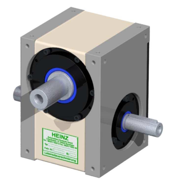


1 Operating Instructions Parallel shaft cam gear Type : Serial No. :
2 C O N T E N T S 1. General 1.1 Validity 1.2 Safety instructions 1.3 Shipment 1.4 Transport Regulations 1.5 Weights of gear types 2. Instructions for application of the gears 2.1 Installation position 2.2 Mounting of the gear 2.3 Gear operation 3. Start up 3.1 Gear function 3.2 Oil level 3.3 Interruption operation 3.4 Important instructions 4. Maintenance Instructions 4.1 General remark 4.2 Drive 4.3 Motor brake 4.4 Gear 5. Inspection instructions 5.1 Inspection cycle Hour-Service 6. Spare part installation 6.1 Remark 6.2 Parallel shaft mechanism Replacing cam followers (parallel shaft cam stays built in) Replacing turret (parallel shaft cam stays built in) Replacing parallel shaft cam (turret stays built in) Replacing mechanism completely 6.3 Tapered roller bearings 6.4 Spare part drawing 6.5 Spare and wearing parts 7. Final remark BWV_HSP_ E 2 / 16
3 1 General 1.1 Validity These operating instructions are valid for parallel shaft cam gears. They are to be read and applied by all persons in the user s premises who are made responsible for the installation, operation, maintenance or repair of these gears. For the sake of simplicity, the parallel shaft cam gears will be referred to as the gears within the following instructions. Every gear is manufactured to the state-of-the-art and according to recognized safety regulations. Applications other than specified or exceeding the limiting parameters, e.g. higher speeds and/or loads or other installation positions, are considered to be contrary to agreement. The manufacturer shall not be held responsible for any damage resulting from this. In such cases, the risk is carried solely by the operating company. The agreement regarding application also covers reading the operating instructions and compliance with the inspection and maintenance stipulations. Maintenance work may only be carried out by qualified personnel who are acquainted with the principles of the gear function. 1.2 Safety instructions The gear corresponds to the recognized safety regulations. When employed as part of a machine or plant, danger of injury or death for the user or a third person can result, e.g. due to removal of the lever, gear wheel with chain or similar parts. In such cases, suitable local protective measures should be taken by the user. 1.3 Shipment Every gear is subjected to go through an inspection process and is properly packed. In spite of this, we request that the gear is unpacked immediately on arrival at the installation location and checked for transport damage. Any complaints should be reported immediately to the transport company. 1.4 Transport regulations Eyebolts may be screwed into the fixing holes provided. Lifting ropes or chains may only be applied on these eyebolts. The weight of the gear should be taken from table 1.5. BWV_HSP_ E 3 / 16
4 1.5 Weight of the gears Basic series Gear type Housing Weight without motor [kg] HSP 40 GG 4,5 HSP 50 GG 7,5 HSP 63 GG 12,5 HSP 80 GG 25,0 HSP 100 GG 43,0 HSP 125 GG 77,0 HSP 160 GG 150 HSP 200 GG 280 HSP 250 GG 480 Modified series HSP 315 GG 680 Gear type Housing Weight without motor [kg] HSP 65 GG 14,5 HSP 80 X GG 27,0 HSP 80 XK GG 27,5 HSP 105 GG 48,0 HSP 130 GG 85,0 BWV_HSP_ E 4 / 16
5 2. Instructions for application of the gears 2.1 Installation position Due to its universal construction, the gear can be integrated into a machine or a plant in nearly every position required. When placing the order, the customer can preset the installation position, the mounting position and possibly the oil holes. The predetermined installation position is decisive for the lubrication of the gear components and may therefore not be subsequently altered at the plant location. Illustration 1: Gear installation positions 2.2 Mounting the gear Due to the principle of the functioning of the gear, the output shaft as well as the input shaft are subjected to variable torques. The following must therefore be observed: The gear must be mounted on a rigid machined surface. The fixing bolts must be secured and, if possible, the position of the gear should be additionally fixed by means of dowel pins. The connection between the gear and the driven load must be direct, free of play and torsionally rigid. This also applies to the drive side of the gear. 2.3 Gear operation The following should be observed with regards to gear operation: Elasticity and play in the driven masses can result in vibration and must therefore be avoided. A possibly installed overload protection should be mounted on the output shaft. BWV_HSP_ E 5 / 16
6 3. Start up 3.1 Gear function HEINZ gears form a compact, robust unit which, through the use of accurately calculated disk cams, enable the transformation of a constant input speed into an optimum, precise and impact-free (intermittent) output movement. The cam rollers fitted in the turret are guided precisely in the curve by the hardened and ground cam path. This cam path is formed with a variable slope and is divided into a dwell angle and index angle area. When the cam is rotated, the precise jolt and impact-free movement of the output shaft is produced by the cam path and the cam follower. As the cam course is constructed standard symmetrically. The dwell angle area has a zero slope. Through this, the cam followers result in a precise, selflocking positioning of the output shaft without an additional locking mechanism. When a brake motor is employed, the positioning of the output shaft is independent on the braking accuracy of the motor as the accurate positioning is dictated by the position of cam followers in the dwell angle area. The whole dwell angle area is available for braking (see 3.3). 3.2 Oil level The oil level should be checked before start up. It is sufficient it the oil can be observed through the oil level indicating glass (see also 4.3 gear) Basic series Gear type oil volume [ L ] Gear type oil volume [ L ] modified series oil volume Gear type [ L ] HSP 40 0,2 HSP 160 8,0 HSP 65 0,4 HSP 50 0,3 HSP ,0 HSP 80X 1,0 HSP 63 0,5 HSP ,0 HSP 80XK 1,0 HSP 80 1,0 HSP ,0 HSP 105 2,0 HSP 100 2,0 HSP 130 3,5 HSP 125 4,0 BWV_HSP_ E 6 / 16
7 3.3 Interruption Operation If the dwell angle area of the disk cam is insufficient for the interval of interruption required for production, the interval can be prolonged by using a brake motor. The procedure is initiated by an end position switch which is operated by one of the cams connected to the input shaft. During the start up as well as during operation it has to be observed that after the braking has occurred, the shaft key groove of the input shaft has to be positioned parallel to face 3 of the housing and that it points towards the output shaft ( in case of double shift also a torsion of 180 is possible, cam followers should be in the middle of the dwell). If the gear is fitted with an additional indicator, it should be observed that after braking has occurred, the indicator is always positioned in the middle of the marking plate. 3.4 Important Instructions With two speed drives, normal operation occurs always at the higher speed (high speed). The lower speed (low speed) may only be used for setting up the unit or moving into the dwell angle area after an emergency stop. During automatic operation, the gear may not be switched into the low speed position while the unit is in the movement phase. With control systems which only allow switching of the high speed through the low speed, this may only occur during the dwell angle, this means during the standstill period of the output shaft or rather within the marking plate. Any damage which is caused by failure in complying with these instructions will result in the rejection of any guarantee claim by the manufacturer. BWV_HSP_ E 7 / 16
8 4. Maintenance Instructions 4.1. General Remark In case of queries i.e. spare part orders, please state the type and serial number of the gear in question. 4.2 Drive The maintenance instructions for the gear brake motor or other drive units should be taken from the instructions supplied by the corresponding manufacturer. 4.3 Motor brake Due to wear of motor brake, the interruption in the dwell angle area as described in 3.3. should be checked from time to time. The brake should be re-adjusted or renewed if necessary. BWV_HSP_ E 8 / 16
9 4.4 Gear unit Oil Lubrication In Standard the gear unit is delivered with the synthetic lubricating oil Klübersynth GHE It is lubricated for life, i.e. no oil changes are necessary at all. The oil level should be checked at regular intervals. Sufficient oil is present if when the gear unit is stationary the oil can be seen in the sightglass The lubrication of the cam rollers and the came is thus guaranteed For rotating speed < 150 rpm For rotating speed > 150 rpm Klübersynth GHE Klübersynth GHE Mobil Glygoyle HE 460 (ISO V6 460) Mobil Glygoyle 22 (ISO V6 150) Shell Omala S4 WE 460 Shell Omala S4 WE 150 WARNING WARNING Warning: Never mix different oil sorts! Only top up with the lubricant described above! If used for the food industry, the gear unit is delivered with NSF H1 registered, conform to FDA 21 CFR oil "Klübersynth UH " It is lubricated for life, i.e. no oil changes are necessary at all. The oil level should be checked at regular intervals. Sufficient oil is present if when the gear unit is stationary the oil can be seen in the sightglass The lubrication of the cam rollers and the came is thus guaranteed For rotating speed < 150 rpm For rotating speed > 150 rpm Klübersynth UH Klübersynth UH WARNING WARNING Warning: Never mix different oil sorts! Only top up with the lubricant described above! Grease Lubrication It is lubricated for life, i.e. no grease are necessary at all. The grease level should be checked at regular intervals. Normal Grease Lubrication NSF H1 registered, conform to FDA 21 CFR Castrol Olit 00 Cassida RLS 00 Microlube GB 00 Klübersynth UH WARNING WARNING Warning: Never mix different oil sorts! Only top up with the lubricant described above! BWV_HSP_ E 9 / 16
10 5. Inspection instructions 5.1 Inspection Cycle It is recommended to control the oil level approximately every 8000 operation hours in order to avoid any damage of the gear by leakage of oil Hour Service Immediate availability of important components is guaranteed through stocking of a stand-by set (disk cams, output and cam followers) by the unit operator. BWV_HSP_ E 10 / 16
11 6. Spare parts installation 6.1 Remark Please read the following complete text carefully before the disassembly. All construction elements have to be cleaned and to be checked if they are in perfect condition before being installed. The list of spare parts may be helpful for the disassembly and the installation of the individual parts. 6.2 disk cam mechanism The mechanism is a unit consisting of two disk cam, cam followers and turret. Due to a possible wear of the cam followers or the parallel shaft cam, it may be necessary to replace the following parts: Cam followers Turret Parallel shaft cam Complete mechanism Replacing cam followers (parallel shaft cam stays built in) Drain oil Move input shaft into dwell angle area Unscrew end cap of output shaft Lift output shaft out of parallel shaft housing Unscrew stud bolts off turret (are glued in) and remove cam followers Check shaft bore of cam followers in the turret if they are damaged and possibly widened In case of defective bores: see In case of perfect condition of bores, push in new cam followers into turret In case of cam followers without key way, bore with core hole drill a centralisation in every cam followers shaft. The depth of centralisation depends on the centralisation point of the stud bolts according to DIN914 (German Industrial Standard) Secure cam followers with stud bolts (glue thread in) Check parallel shaft cam and replace by a new one if necessary (see chapter 6.2.3) Put output shaft with turret back into housing (observe the position of the shaft key groove of the output shaft) BWV_HSP_ E 11 / 16
12 Apply appropriate permanently elastic sealing material upon cleaned sealing surface and install end cap Move input shaft and check regular movement of mechanism Fill in oil Replacing turret ( parallel shaft cam stays built in) In the case of a defective cam followers shaft bore remove (smaller) tapered roller bearing Remove stud bolts off turret and disassemble turret off output shaft Screw tight new turret with installed cam followers again and put in new studs Heat tapered roller bearing slightly (max. 80 C) and push over output shaft Put output shaft with turret back into housing (observe position of shaft key groove of output shaft) Proceed with assembly as describe in chapter Replacing parallel shaft cam (turret stays built in) Drain oil Move input shaft into dwell angle area Screw off housing cover Release safety catch of securing steel sheets and unscrew lock nut Unscrew both eccentric covers Push inner ring of tapered roller bearing (maximum 3 mm less than width of lock nut) off input shaft by using lock nuts Pull off tapered roller bearing by using an extractor Remove lock nut and securing steel sheets Drive input shaft out of parallel shaft cam without using too much power on the cam followers Take old parallel shaft cam out of housing Put new parallel shaft cam with dwell angle area between two cam followers (Observe position of shaft key groove of output shaft) Drive input shaft into cam without using too much power on the cam followers Screw new securing steel sheets and new lock nuts on input shaft Heat tapered roller bearing (max. 80 C) and push over input shaft (replace defective bearings by new ones) Screw off eccentric cover. While doing so, make sure no preloading is produced between cam follower and cam, possibly move cam by using the lock nut or turn eccentric cover Check preloading of tapered roller bearing in dwell angle area, possibly by adjusting the eccentric cover Adjust mechanism without backlash by turning eccentric cover and/or by moving the cam BWV_HSP_ E 12 / 16
13 The height tolerance of the input shaft pivot may not exceed maximum 0,02 mm on the total length of the pivot. An even contact reflection of the cam follower and parallel shaft cam is absolutely required - check with inking past! Screw lock nuts tightly and secure Screw eccentric cover tightly Turn input shaft with hand and check its even running, possibly repeat adjustment Cover all openings Put pins into eccentric cover (possibly earmark pin holes on same pc-diameter with same depth of bores, remove chips) Screw off eccentric cover, seal, bring into line above pin bore, tighten slightly, push pins and screw tightly Install new oil seals seal housing cover and screw tightly Fill in oil Replacing mechanism completely Please refer to chapter to for the instructions for disassembling and installation of the turret. 6.3 Tapered roller bearing When installing new tapered roller bearings, it has to be observed that the bearings are adjusted free of play. If the backlash is to high or too low, this can be corrected by adjusting the housing cover or eccentric cover. Afterwards check the correct running of the mechanism by turning the input shaft, readjust if necessary. BWV_HSP_ E 13 / 16
14 6.4 Spare part drawing BWV_HSP_ E 14 / 16
15 6.5 Spare and wearing parts 1. Mechanism 1.1 Parallel shaft cam 1.2 Turret 1.3 Cam followers 2. Bearing set 2.1 Tapered roller bearing output Tapered roller bearing output Tapered roller bearing output 3. Sealing set 3.1 Oil seal output 3.2 Oil seal input 3.3 O-Ring output 3.4 O-Ring input 4. Input shaft 5. Output shaft 7. Final remark All repair work requires a certain amount of experience and should therefore be carried out by HEINZ fitters. Address of HEINZ: HEINZ AUTOMATIONS-SYSTEME GmbH Lilienthalstr Bensheim Tel.: +49 (0)6251 / Fax: +49 (0)6251 / mail@heinz-automation.de BWV_HSP_ E 15 / 16


16 Lilienthalstrasse 21 - D Bensheim Telefon +49(0)6251/ Fax +49(0)6251/ BWV_HSP_ E 16 / 16
Operating Instructions. Globoidal cam gear
 Operating Instructions Globoidal cam gear Type : Serial No. : TABLE OF CONTENTS 1. General 1.1 Validity 1.2 Safety instructions 1.3 Shipment 1.4 Transport Regulations 1.5 Weights of gear types 2. Instructions
HP High-Performance Gear Units with <2' Adjustable Backlash
 Page HP High-Performance Gear Units with
Operating and Maintenance Manual. for. HADEF overhead crane. as jointed crane TA
 5.52.714.00.1.0 Edition 03.2004 GB Operating and Maintenance Manual for HADEF overhead crane as jointed crane TA Subject to changes. 1 HADEF Table of Contents 1 General Page 3 2 Product description Page
Assembly and Maintenance Manual Type RSBW
 Assembly and Maintenance Manual Type RSBW Hatschekstr. 36 69126 Heidelberg Germany Tel +49(0)6221 30470 Tel +49(0)6221 304731 info@stieber.de www.stieber.de Stieber Clutch Date of issue: 16/03/2017 GB
Assembly and Maintenance Manual Type ASNU
 Assembly and Maintenance Manual Type ASNU Hatschekstr.36 69126 Heidelberg Germany Tel +49(0)6221 30470 Fax +49(0)6221 304731 info@stieber.de www.stieber.de Date of issue: 30.05.2018 GB Revision: 0 U:\EngUsers\!ProduktDoku\1AAA_Einbauerklaerung_Wartungsanleitung_Konformitaetserklaerung\1AAA_Wartungsanleitungen\Orginal_Worddatei\_ASNU.docx
RADEX -N Composite Operating/Assembly instructions
 1 of 14 RADEX -N is a torsionally stiff flexible steel lamina coupling. It is able to compensate for shaft misalignment, for example caused by thermal expansion, etc. note ISO 101. Drawn: 0.05.15 Kb/Wig
Mounting and Operating Instructions EB 8135/8136 EN. Series V2001 Valves Type 3535 Three-way Valve for Heat Transfer Oil
 Series V2001 Valves Type 3535 Three-way Valve for Heat Transfer Oil Type 3535 Three-way Valve with bellows seal and rod-type yoke (partial view) Mounting and Operating Instructions EB 8135/8136 EN Edition
Instructions for Use Plain Trolley ULK Geared Trolley UHK
 Instructions for Use Plain Trolley Geared Trolley Item no. Load-carrying capacity (payload) Weight Trolley widths *special trolley widths* Device dimensions mm H / W / D Minimum curve radius mm -005 0,5
Operating Instructions
 Operating Instructions Table of contents Table of contents... 1 1. Declaration... 1 2. Warranty and liability... 2 3. Gear description... 2 4. Gear types... 2 5. Safety... 3 5.1 General safety information...
Operating manual Separator
 Operating manual Separator Sheet no. AS/4.1.141.1.1 issue 20.08.2014 Contents Section Title Page 0 Introduction... 1 1 Intended use......1 2 Marking of the fitting... 1 3 Safety instructions... 2 4 Transport
Product Information Overspeed governor GB 260
 Product Information GB 260 Copyright as per DIN ISO 16016. Manufactured under licence of C. Haushahn GmbH & Co. I Subject to modification. Published by SLC Sautter Lift Components GmbH & Co. KG Borsigstrasse
Assembly and Maintenance Manual Type AS
 Assembly and Maintenance Manual Type AS Hatschekstr.36 69126 Heidelberg Germany Tel +49(0)6221 30470 Fax +49(0)6221 304731 info@stieber.de www.stieber.de Date of issue: 30.05.2018 GB Revision: 0 U:\EngUsers\!ProduktDoku\1AAA_Einbauerklaerung_Wartungsanleitung_Konformitaetserklaerung\1AAA_Wartungsanleitungen\Orginal_Worddatei\_AS.docx
EU DECLARATION CONFORMANCE
 LOGIFLEX ELF / ELFS EU DECLARATION CONFORMANCE Manufacturer: Logitrans A/S Hillerupvej 35 DK-6760 Ribe Denmark It is hereby declared that: Machine: Productgroup: Logiflex Type: ELF/ELFS Year of manufacture/
For advanced drive technology CLAMPEX. Shaft-hub-connection. KTR Precision joints CLAMPEX
 technology CLAMPEX Shaft-hub-connection CLAMPEX KTR Precision joints 227 technology Table of contents Page Brief information 228 Selection and calculation 25-255 CLAMPEX -Selection Shaft diameter = d 0
D58 Series Brake Instructions
 D58 Series Brake Instructions 4740 W. Electric Avenue Milwaukee, WI 53219 414/672-7830 FAX 414/672-5354 www. dingsbrakes.com Safety information 2 Safety information 2.1 Persons responsible for the safety
Technical Specifications
 Technical Specifications Overview RollerDrive CNC The answer for a CNC rotary axis Pure Motion By Zero-Backlash Technology TM The RollerDrive CNC, a CNC rotary table, is designed to fulfill the demands
Installation and Operating Instructions for EAS -NC clutch Type 45_. _. _ Sizes 02 and 03
 Table of contents: Please read and observe this Operating Instruction carefully! A possible malfunction or failure of the clutch and any damage may be caused by not observing it. Page 1: - Table of contents
Operating Instructions Thread Rolling Heads F 001, F 01, K 01-1
 Head in fixed application (for F and K types): The front part of the head is turned by using the handle (25) with the ball (23) (if used on automatics, closing is accomplished by using closing roller over
Drive Unit e-drive1. Installation instructions 04/2014. English translation of the original German installation instructions
 Drive Unit e-drive1 Installation instructions 04/2014 English translation of the original German installation instructions Contents Foreword... 3 Availability... 3 Structural features in the text... 3
For advanced drive technology CLAMPEX. Shaft-Hub-Connection. KTR Precision Joints CLAMPEX
 technology CLAMPEX Shaft-Hub-Connection CLAMPEX KTR Precision Joints 07 technology Table of contents Page Brief information 09 Selection and calculation -5 CLAMPEX -Selection Shaft diameter = d 0 10 0
Translation of the Original operating instructions Lifting device Z 70 /...
 Translation of the Original operating instructions Lifting device Z 70 /... Content 1. Lifting device / Correct use according to regulations 2. Basic principles 3. General information 4. Special remarks
V SWISS MADE LINEAR TECHNOLOGY
 Compact units Excerpt from main catalogue SWISS MADE LINEAR TECHNOLOGY V 11-15 Line Tech compact units Table of contents Product overview 106 107 Design fundamentals / Lubrication / Maintenance 108 Profile
Selection Tool. on the Internet at in the section MÄDLER -Tools. Other sizes and designs on request. Connecting Shafts Page 766
 Couplings Overview Friction Clutches Friction Clutches Type B Axial Arrangement Friction Clutches Type C Transversal Flexibility Sliding Hubs with Torsionally-Flexible Coupling Multi-Disk Friction Clutches
Instruction and Installation Manual
 Instruction and Installation Manual ROSTA Tensioner Devices Tensioners Accessories -G -W -R Sprocket wheel N Chain rider P Oil resistant Up to + 120 C Reinforced Sprocket wheel set Chain rider set -I -F
Installation and Operational Instructions for EAS - HTL housed overload clutch Sizes 01 3 Type 490._24.0
 Please read these Operational Instructions carefully and follow them accordingly! Ignoring these Instructions may lead to malfunctions or to clutch failure, resulting in damage to other parts. Contents:
Roller chain idler sprocket units Idler pulley units
 Roller chain idler sprocket units Idler pulley units Roller chain idler sprocket units, idler pulley units Page Product overview Roller chain idler sprocket units, idler pulley units... 334 Design and
Mounting and Operating Instructions EB 8039 EN. Type 3351 Pneumatic On/off Valve. Type 3351 Pneumatic On/off Valve. Type 3351 Pneumatic On/off Valve
 Type 3351 Pneumatic On/off Valve Type 3351 Pneumatic On/off Valve Type 3351 Pneumatic On/off Valve Version with handwheel Mounting and Operating Instructions EB 8039 EN Edition May 2016 Definition of signal
Bellows Page 415. Overview Universal Joints. Single Universal Joints. Speeds* max. min
 Overview Universal Joints Single Universal Joints Type UKM GF KE WEL RW AR WE WEN WER Material Plastic Plastic Stainless STAINLESS Bearings Bores mm 2-10 8-16 0-40 6-30 6-45, hardened 6-30, hardened 6-40
Take off case cover.
 33 14 520 Replacing complete locking differential (Type M) - final drive removed - Removing and installing final drive, included in Repair Manual MF, model-dependent, from '85, refer to 33 10 010. Drain
Operating Instruction:
 Operating Instruction: Leakage - Butterfly valve with manual operation Types LSV 4365 LSV 4366 LSV 4367 LSV 4368 LSV 4369 LSV 4370 Kieselmann GmbH Paul-Kieselmann-Str. 4-10 75438 Knittlingen Telefon +49
Belt Conveyor Pull Rope Switch Types HEN, HEK and SEM OPERATING INSTRUCTIONS
 Belt Conveyor Pull Rope Switch Types HEN, HEK and SEM OPERATING INSTRUCTIONS 2 CE-Sign and Conformity The device meets the requirements of the valid European and national regulations. Conformity has been
Sensor-Bearing Units Steer-By-Wire Modules Mast Height Control units Other sensorized units
 Mechatronics Sensor-Bearing Units... 957 Steer-By-Wire Modules... 967 Mast Height Control units... 969 Other sensorized units... 971 955 Sensor-Bearing Units SKF Sensor-Bearing Units... 958 SKF Explorer
IP 900 W/KS & IP 900 D/KS
 B W/KS & D/KS Installation and operating instructions We reserve the right to make modifications in the interest of technical development (4) 15975178 GB 04/05 1 pplication reas The submersible waste-water
Operating and installation instructions
 Pneumatic actuators DP34 Tandem / DP34 Tridem DP34T Contents DP34Tri 1.0 General information on operating instructions...2-2 2.0 Notes on possible dangers...2-2 2.1 Significance of symbols...2-2 2.2 Explanatory
INDEX. 414 Agitator reversing mechanism which varies point of reversal. 250 Alternate and intermittent drive for two shafts
 INDEX Agitating device for pin hopper.----------------------------------------- 414 Agitator reversing mechanism which varies point of reversal. 250 Alternate and intermittent drive for two shafts.-----.----------.--..--
Mounting and Operating Instructions EB 8097 EN. Type and Type Pneumatic Control Valves
 Type 3347-1 and Type 3347-7 Pneumatic Control Valves Type 3347-7, cast body with welding ends Type 3347-7, bar stock body with threaded connections Mounting and Operating Instructions EB 8097 EN Edition
Crossed Roller Ways. Description of each series and Table of dimensions. Anti-Creep Cage Crossed Roller Way
 Crossed Roller Ways Description of each series and Table of dimensions Crossed Roller Way Page - to -7 Anti-Creep Cage Crossed Roller Way Page - to - Crossed Roller Way Unit Page - to - In the table of
BoWex FLE-PA. BoWex FLE-PAC. KTR-N Sheet: Edition: EN 1 of BoWex FLE-PA / FLE-PAC Operating/Assembly instructions
 1 of 17 is a torsionally rigid flange coupling. It is able to compensate for shaft misalignment, for example caused by manufacturing inaccuracies, thermal expansion, etc. BoWex FLE-PA BoWex FLE-PAC Drawn:
Service manual. Gear pumps - series T3S
 Service manual Gear pumps - series T3S 1. Basic description Gear pumps serve to transform mechanical energy into pressure energy of a liquid. T3S line pumps with external helical gearing can be used -
AGN 076 Alternator Bearings
 Application Guidance Notes: Technical Information from Cummins Generator Technologies AGN 076 Alternator Bearings BEARING TYPES In the design of STAMFORD and AvK alternators, the expected types of rotor
Compensation unit AGE-XY 50-80
 Translation of the origninal manual Compensation unit AGE-XY 50-80 Assembly and operating manual Superior Clamping and Gripping Imprint Imprint Copyright: This manual remains the copyrighted property of
back to main page Type: Butterfly valves Instructions and Operation Manual Warning! Warning! Danger for life! 1. Intended use Danger for life!
 Instructions and operation manual for butterfly valves This manual is intended to support the users of Herberholz butterfly valves type HRD/HRA, RD/RA, LDKE/LDKF for installation, operation and maintenance
Operating Instructions for Elevator Buffers type LP
 Operating Instructions for Elevator Buffers type LP 1 Scope of application The Elevator Buffer type LP is an energy dissipation type buffer according to EN 81-1/2, EN 81-20, EN 81-50 5.5 and therefore
Operating Instructions ROCO Butterfly Valve with SKG Slider-crank Mechanism, with Electric Multi-turn Actuator
 Operating Instructions ROCO Butterfly Valve with SKG Slider-crank Mechanism, with Electric Multi-turn Actuator 1 Product and Performance Description 2 Design Features of ROCO Butterfly Valve 3 Installation
A408 GB. Pneumatic oil and diesel pumps 1:1
 03 594 A408 GB Pneumatic oil and diesel pumps 1:1 G Operating instructions for Pneumatic oil and diesel pump 1:1 Contents 1. General details 2 1.1 Intended use 2 1.2 Design and functional description 2
DeZURIK " BAW AWWA BUTTERFLY VALVES WITH EPOXY-RETAINED SEAT
 DeZURIK 20 144" BAW AWWA BUTTERFLY VALVES WITH EPOXY-RETAINED SEAT Instruction D10373 April 2017 Instructions These instructions provide information about the 20 (250 F2 model only) and the 24-144 BAW
Hoist Brake Motor. Hoist Gearbox Reeving Wire Rope Construction
 DR11 Monorail Hoist Hoist Brake Motor Hoist Gearbox Reeving Wire Rope Construction Rope Drum Trolley Brake Motor Trolley gearbox Trolley Trolley Wheels Load Block Hoist VFD Controls Trolley VFD Controls
OVERLOAD CLUTCHES FOR INDEX DRIVES
 The Driving Force in Automation OVERLOAD CLUTCHES FOR INDEX DRIVES WARNING WARNING This is a controlled document. It is your responsibility to deliver this information to the end user of the CAMCO indexer.
Take off case cover.
 33 14 520 Removing complete locking differential. (Type K) - final drive removed - Removing and installing final drive, refer to 33 10 010 Drain off fluid. Secure final drive to special tool 33 1 010 (retaining
FAG Wheel Bearing Repair Solution for Light Commercial Vehicles
 FAG Wheel Bearing Repair Solution for Light Commercial Vehicles Mercedes-Benz Sprinter, Viano, Vito and Volkswagen Crafter Front Axle The content of this brochure shall not be legally binding and is for
Operating Manual for extrusion valve MMKD-40 KV/LV/LVP
 Operating Manual for extrusion valve MMKD-40 KV/LV/LVP Read this manual carefully before installing, operating or servicing this equipment. Keep always handy for further use. ALFRED SCHÜTZE Apparatebau
Electropneumatic Converters i/p Converters Type 6111 Mounting and Operating Instructions EB 6111 EN
 Electropneumatic Converters i/p Converters Type 6111 Fig. 1 Type 6111 in standard version Fig. Type 6111 mounted on a supply air manifold Fig. 3 Type 6111 in field enclosure Mounting and Operating Instructions
COLOMBO FILIPPETTI SPA
 PARALLEL OSCILLATING DRIVES CF3 COLOMBO FILIPPETTI SPA HEAVY-DUTY SERIES 165P 200P 250P 315P LA MECCANICA RAZIONALE Via Rossini, 26-24040 CASIRATE D'ADDA [BG] - ITALY - TEL.0363/3251 - TELEFAX 0363/325252
The Available Solution CYCLO DRIVE. Gearmotors & Speed Reducers. Series
 The Available Solution CYCLO DRIVE Gearmotors & Speed Reducers 6000 Series WHAT DO YOU THINK OF THIS? THESE ARE THE ADVANTAGES OF THE NEWEST CYCLO, 6000 SERIES: More frame sizes, gear ratios and motor
ROSTA MOTORBASES ROSTA. Self-Tensioning Motor Mount for Belt Drives. without slippage self-adjusting maintenance-free
 MOTORBASES Self-Tensioning Motor Mount for Belt Drives without slippage self-adjusting maintenance-free Technology Tensioning Motorbase Type MB for Belt Drives The elastic tensioning motorbase type MB,
Mounting and Operating Instructions EB 3913 EN. Electropneumatic Converters i/p Converter Type
 Electropneumatic Converters i/p Converter Type 3913-0001 Fig. 1 Type 3913-0001 Electropneumatic Converter with pressure gauge and bracket Mounting and Operating Instructions EB 3913 EN Edition August 2011
INSTALLATION AND MAINTENANCE MANUAL Rev. 12/2015 Deda Elementi. seat post. seat post
 INSTALLATION AND MAINTENANCE MANUAL Rev. 12/2015 Deda Elementi seat post UK seat post Thank you for choosing a DEDA ELEMENTI and MUD product. We at DEDA ELEMENTI develop, manufacture, and constantly test
Mounting and Operating Instructions EB 8048 EN. Type and Type Pneumatic Control Valves Type 3249 Aseptic Angle Valve
 Type 3249-1 and Type 3249-7 Pneumatic Control Valves Type 3249 Aseptic Angle Valve Ball body version Special version with packing Type 3249-7 Control Valve with Type 3277 Actuator and integrated positioner
Operating / Assembly Instructions Type A and CS Coupling
 Page: 1 of 14 Subject Index 1. Technical Data 2. Hints 2.1. General Hints 2.2. Warning and Safety Hints. 2.3. General Hints to Danger. 2.4. Proper use. 3. Storage. 4. Assembly. 4.1. Coupling components.
Ball Rail Systems RE / The Drive & Control Company
 Ball Rail Systems RE 82 202/2002-12 The Drive & Control Company Rexroth Linear Motion Technology Ball Rail Systems Roller Rail Systems Standard Ball Rail Systems Super Ball Rail Systems Ball Rail Systems
Fuse state indicator MEg72. User manual
 Fuse state indicator MEg72 User manual MEg Měřící Energetické paráty, a.s. 664 31 Česká 390 Czech Republic Fuse state indicator MEg72 User manual Fuse state indicator MEg72 INTRODUCTION The fuse state
Operating and Maintenance Instructions. Abteilung TB, Schell Seite 1 8 SERIES 56
 Abteilung TB, Schell Seite 1 8 These instructions supersede all earlier instructions, in particular BWS 109-0 till BWS 109-3. For applications in areas with explosion hazard it is obligatory to observe
Storage, operating and maintenance instructions for AZ plug valves and Standard valves
 ARMATUREN Plug - Valves metallic with PTFE Sleeve 2-7 way Storage, operating and maintenance instructions for AZ plug valves and Standard valves Plug - Valves FEP/PFA - lined, 2-3 way Butterfly - Valves
Service manual. Gear pumps - series QHD
 Service manual Gear pumps - series QHD 1. Basic description Gear pumps serve to transform mechanical energy into pressure energy of a liquid. The series pumps are designed primarily for use in mobile hydraulics
Mounting Tools 2 Checking Clearances 3 Components 4-5 Mounting 6-21 Correct Method of Tensioning the Chain 22 Adjusting The Overall Dimension 23-24
 Mounting Tools 2 Checking Clearances 3 Components 4-5 Mounting 6-21 Correct Method of Tensioning the Chain 22 Adjusting The Overall Dimension 23-24 Maintenance 25 Repairing Main Body Patterns 26 Removal
Mounting instructions Directions for use MAKROLUX. Halogen-spot lamp for consulting room and hospital
 Mounting instructions Directions for use MAKROLUX Halogen-spot lamp for consulting room and hospital Stand model with five-feet base, design without heat protection filter 1100 1012 00 Stand model with
SNN SPLIT PLUMMER BLOCKS
 SNN SPLIT PLUMMER BLOCKS SNN SPLIT PLUMMER BLOCKS FROM NSK The SNN split plummer block from NSK combines quality materials and design to maximize bearing performance. With features like serialized cap
Adjustable Speaker Mount GRAVIS 8
 Adjustable Speaker Mount GRAVIS 8 User's Manual Translation of the original instructions Important Information, Please Read Before Use! KLING & FREITAG GmbH Junkersstraße 14 D-30179 Hannover TEL +49 (0)
Assembly and maintenance manual Type FSO, FSO-GR, FS, HPI
 Type FSO, FSO-GR, FS, HPI Hatschekstr.36 69126 Heidelberg Deutschland Tel +49(0)6221 30470 Fax +49(0)6221 304731 info@stieber.de www.stieber.de Date of issue: 23.08.2018 GB Revision: 0 U:\EngUsers\!ProduktDoku\1AAA_Einbauerklaerung_Wartungsanleitung_Konformitaetserklaerung\1AAA_Wartungsanleitungen\Orginal_Worddatei\M1124E_0_FSO_FSO-GR_FS_HPI.docx
Adjustable Speaker Mount GRAVIS 12
 Adjustable Speaker Mount GRAVIS 12 User's Manual Translation of the original instructions Version 3.3 Released: 19.01.2017 Important Information, Please Read Before Use! KLING & FREITAG GmbH Junkersstraße
INSTRUCTIONS FOR USE FACE GEARBOXES
 INSTRUCTIONS FOR USE FACE GEARBOXES TNC MTC-TC KTM ES Declaration of Conformity Producer: TOS ZNOJMO, akciová společnost Družstevní 3 CZ 669 02 Znojmo Equipment: Face gearboxes Type/ Modification:MTC,
Operating Instruction
 Operating Instruction Drive element LEWA - ecosmart type LCA with manual stroke adjustment, motor mounted vertically Table of contents 1 General information / safety 1.1 Important preliminary information
Bowl feeder WV401-1 / Translation of operating and installation instructions
 Bowl feeder WV401-1 / 402-1 Translation of operating and installation instructions Copyright by Afag GmbH This operation instruction applies to: Bowl feeder WV401-1 Bowl feeder WV402-1 Type 230 V / 50
VBK 2596/12E/RSF. Thickness and Width Gauge for Strip and Profile. Operating- & Service Instructions. (with lateral guide rollers)
") Thickness and Width Gauge for Strip and Profile (with lateral guide rollers) VBK 2596/12E/RSF Operating- & Service Instructions erstellt am 5.2.1998 freigegeben am Bemerkungen Rev.01 Seiten:16 Name: Rietdorf
Thickness and Width Gauge for Strip and Profile (with lateral guide rollers) VBK 2596/12E/RSF Operating- & Service Instructions erstellt am 5.2.1998 freigegeben am Bemerkungen Rev.01 Seiten:16 Name: Rietdorf
OPERATING INSTRUCTIONS Thread unscrewing unit Z 5410, Z5420, Z5430
 STRACK NORMA GmbH & Co. KG Postfach 16 29 58466 Lüdenscheid Königsberger Str. 11 58511 Lüdenscheid Tel.: 0 23 51 / 87 01-0 Fax: 0 23 51 / 87 01-100 E-Mail: info@strack.de http://www.strack.de D 8138E 02.2009
HCS14/16/18 Hydraulic Cut-off Saw. Prior to Operation. We thank you for choosing a HYCON cut-off saw.
 Prior to Operation HCS14/16/18 Hydraulic Cut-off Saw From serial No. 0164 Revised September 2003 HYCON A/S Vester Hassingvej 33 DK-9320 Hjallerup Denmark Tel: +45 9647 5200 Fax: +45 9647 5201 Mail hycon@hycon.dk
Rotary feed-through DDF-S/-KS
 Translation of the Original Operating Manual Rotary feed-through DDF-S/-KS Assembly and Operating Manual Superior Clamping and Gripping Imprint Imprint Copyright: This manual remains the copyrighted property
Operating and installation instructions
 DP30 DP32 DP33 DP34 Contents 1.0 General information on operating instructions... 2-2 2.0 Notes on possible dangers... 2-2 2.1 Significance of symbols... 2-2 2.2 Explanatory notes on safety information...
Instructions for Fitting, Operating and Maintenance Canopy Door RE / (St.: )
") EN Instructions for Fitting, Operating and Maintenance Canopy Door 1 818 012 RE / (St.: 12.2010) 12.2010 ENGLISH Contents 1 Safety Instructions... 3 1.1 Qualified persons... 3 1.2 Symbols and signal words
EN Instructions for Fitting, Operating and Maintenance Canopy Door 1 818 012 RE / (St.: 12.2010) 12.2010 ENGLISH Contents 1 Safety Instructions... 3 1.1 Qualified persons... 3 1.2 Symbols and signal words
INSTALLATION, OPERATION AND MAINTENANCE INSTRUCTIONS
 INSTALLATION, OPERATION AND MAINTENANCE INSTRUCTIONS Contents Section 1. General Observations... 2 2. Operation... 4 3. Control During Operation... 5 4. Trouble Shooting... 6 5. Maintenance... 7 Please
OPERATION & SERVICE MANUAL DRUM (MANUAL DRUM LIFTER)
") OPERATION & SERVICE MANUAL DRUM-55-36 (MANUAL DRUM LIFTER) Vestil Manufacturing Corp. 2999 North Wayne St., Angola, IN 46703 Ph: 260-665-7586. Fax: 260-665-1339 E-mail: Sales@vestil.com Website: www.vestil.com
OPERATION & SERVICE MANUAL DRUM-55-36 (MANUAL DRUM LIFTER) Vestil Manufacturing Corp. 2999 North Wayne St., Angola, IN 46703 Ph: 260-665-7586. Fax: 260-665-1339 E-mail: Sales@vestil.com Website: www.vestil.com
REPAIR MANUAL. Version 02/11/01 CD ZF GETRIEBE GMBH SAARBRÜCKEN
 REPAIR MANUAL 6 HP-26 Version CD ZF GETRIEBE GMBH SAARBRÜCKEN subject to alterations Copyright 2002 all rights reserved and published by ZF Getriebe GmbH, Saarbrücken, Department MKTD No part of this manual
OPERATING INSTRUCTIONS INDEPENDENT WHEEL SUSPENSION RL 75 E/EC FRONT AXLE/TAG AXLE RL 75 A
 INDEPENDENT WHEEL SUSPENSION RL 75 E/EC FRONT AXLE/TAG AXLE RL 75 A 587.97.90 en Preface This documentation has been developed for specialized staff trained by ZF Friedrichshafen AG for repair and maintenance
Tension Meter. PT Series. Instruction Manual PT-100-L. Valid as of: Please keep the manual for future reference!
 Tension Meter S C H M I D T PT Series c o n t r o l i n s t r u m e n t s Edition PT 01.0.E Model PT-100 PT-100-L Instruction Manual Valid as of: 15.04.2011 Please keep the manual for future reference!
ZG-ZS. Geared scroll chucks. Geared scroll chucks ZG-ZS
 The spiral ring chuck - a proven and universal suitable clamping system - finds it s application wherever a high clamping force, high runout accuracy and very high repeatability are required. For use on
Mounting and operating instructions EB 5801 EN. Electric Actuators Type 5801 (Rotary Actuator) Type 5802 (Linear Actuator)
 Type 5802 (Linear Actuator)") Electric Actuators Type 5801 (Rotary Actuator) Type 5802 (Linear Actuator) Linear Actuator with Type 3260 Control Valve Rotary actuator with lever system Linear actuator with Type 3321 (V2001) Control
Electric Actuators Type 5801 (Rotary Actuator) Type 5802 (Linear Actuator) Linear Actuator with Type 3260 Control Valve Rotary actuator with lever system Linear actuator with Type 3321 (V2001) Control
Servo-conventional milling machine
 Universal Milling Machine Servo-conventional milling machine Control developed and built in Germany Positioning control for traveling pre-selected paths on all axes Constant cutting speed, whereby the
Product Range Modules ROSTA Tensioner Devices
 Product Range Modules ROSTA Page 17 14 Tensioning Technology Chain Tensioning Roller chains are power transmission components with positive transmission which, by virtue of their design are subject, depending
MEYER-Rotating Fork Positioners are attachments used to transport loads and replace
 This MEYER-Attachment complies in every aspect to the EC-Safety Guidelines. The Certificate of Conformation / Declaration by the Manufacturer has been delivered with the attachment. The CE-Symbol can be
Hand Pallet Truck NC. Operation Manual
 Hand Pallet Truck -------NC Operation Manual Operation Manual 1 Application Range This product is suitable for using in rated load of up to 5500lbs. This PL5500HD is the perfect jack for handling palletized
Bearings and steel balls
 Bearings and steel balls Deep groove ball bearings DIN 625 T1 P. 2-5 Deep groove ball bearings stainless steel DIN 625 T1 P. 2-15 Angular ball bearings DIN 628 T1 P. 2-17 Spindle bearings DIN 628 T1 P.
OPERATING INSTRUCTIONS (Translation) Hoisting crane
 Hoisting crane") 1. User Groups Duties Operator Operation, visual inspection Specialist personnel OPERATING INSTRUCTIONS (Translation) Hoisting crane Type 4781.0,25 Assembly, disassembly, repair, maintenance Tests GB Qualifications
1. User Groups Duties Operator Operation, visual inspection Specialist personnel OPERATING INSTRUCTIONS (Translation) Hoisting crane Type 4781.0,25 Assembly, disassembly, repair, maintenance Tests GB Qualifications
User Guide. Lubricus Lubrication System LUB-D1/LUB-D2/LUB-D3/LUB-D4 (24 VDC)
") User Guide Lubricus Lubrication System LUB-D1/LUB-D2/LUB-D3/LUB-D4 (24 VDC) version 04/2013 Content General Information 3 Warning 3 Scope of Supply 3 Overview 3 General safety details 4 Intended use 4
User Guide Lubricus Lubrication System LUB-D1/LUB-D2/LUB-D3/LUB-D4 (24 VDC) version 04/2013 Content General Information 3 Warning 3 Scope of Supply 3 Overview 3 General safety details 4 Intended use 4
Hot Pressing Device PQ-58
 Habasit AG Postfach, CH-4153 Reinach-Basel Phone ++41 61 715 15 15 Fax ++41 61 715 15 55 Operating Instructions 36007 Author: Gul/Ni/Nyk Page 1 of 20 Replaces: Edition 03/0102 Hot Pressing Device The is
ENGINE WINCHES from 300 to 5000 kg - TS and TD Series
 ENGINE WINCHES from 300 to 5000 kg - TS and TD Series INSTRUCTION MANUAL START-UP AND MAINTENANCE In an endeavor to improve its products, HUCHEZ reserves the right to alter the equipment described herein,
The chronograph calibres CHRO PC 17 jewels CHRO C12 PC 17 jewels CHRO C12 PC AMPM GMT 17 jewels CHRO PC CAL 17 jewels
 Technical guide The chronograph calibres 860 27 CHRO PC 17 jewels 861 27 CHRO C12 PC 17 jewels 910 27 CHRO C12 PC AMPM GMT 17 jewels 930 27 CHRO PC CAL 17 jewels o 27.00 mm / Power-reserve Jewel number
ACTUATOR HON
 ACTUATOR HON 672 672.20 OPERATING AND MAINTENANCE INSTRUCTIONS/ SPARE PARTS EDITION 01/2017 Serving the Gas Industry Worldwide Contents Page 1. General information 3 1.1 Safety information 3 2. Specific
Universal. CNC Turning machine TNA500 TNA600
 Universal CNC Turning machine TNA500 TNA600 TRAUB TNA this name is highly regarded throughout the world for machining large chuck, shaft or bar parts. With their precision and efficiency, short setup time
FLENDER ZAPEX couplings. Type ZWT. Operating instructions BA 3505 EN 10/2011. FLENDER couplings
 FLENDER ZAPEX couplings Type ZWT Operating instructions FLENDER couplings FLENDER ZAPEX couplings Type ZWT Operating instructions Translation of the original operating instructions Technical data Notes
Operating Instructions for Paddle Flowswitch Model: PPS-...
 Operating Instructions for Paddle Flowswitch Model: PPS-... 1. Note Please read and take note of these operating instructions before unpacking and commissioning. The instruments may only be used, maintained