Troubleshooting Power Transmission Couplings
|
|
|
- Gordon Blankenship
- 6 years ago
- Views:
Transcription
1 Troubleshooting Power Transmission Couplings Introduction Power transmission couplings are used to connect two shafts that turn in the same direction on the same centerline. There are three principle types of couplings; rigid, flexible and special purpose. Rigid couplings are used in applications where misalignment is not a factor, where flexibility is not required and where the coupling is not required to absorb load shocks or torque changes. Rigid couplings connect shafts using bolted flanges, keyed sleeves or ribbed clamps bolted together over the shaft ends with keyways. Rigid couplings are used primarily for vertical drive systems. Lubrication is not required, but larger couplings, or those running at high speeds, may require balancing to reduce vibration. Flexible couplings also connect two rotating shafts, but are designed to dampen vibration, absorb some shock loading and provide some axial movement or end float of the shafts, as well as compensate for minor misalignment. There are three fundamental categories of flexible couplings; mechanically flexible, such as gear and chain couplings, material flexible, such as disc, spring, diaphragm, elastomeric and bellows and combination, such as metallic grid couplings, that provide a combination of mechanical and material flexibility. Special purpose couplings include such devices as mechanically flexible Ujoints and constant velocity joints used for automobile applications, magnetic couplings, such as magnet to magnet and eddy current couplings and fluid couplings, such as liquid, silicone and shot filled types. Magnet and fluid couplings provide no contact between drive and driven elements, offer low maintenance and both are capable of absorbing shock loads. 1

2 A unique special purpose type, the Schmidt or offset coupling is designed to handle large parallel shaft offsets of up to 18 inches and 1,000,000 in-lbs of torque. (SEE FIGURE 1.) FIGURE 1. The Schmidt or offset coupling. There are over 80 styles of flexible couplings used today in approximately 90 percent of all industrial applications. The most common are briefly described below under their respective categories. 1. Mechanically flexible couplings, such as gear and chain couplings, provide a flexible connection by permitting coupling components to move or slide over each other. Some minor misalignment is provided by the clearances between gear teeth and chain and sprocket teeth respectively, however shafts should be aligned to less than inches to ensure long coupling life. These coupling types require lubrication using recommended coupling grease or EP oil. As might be expected, approximately 75% of gear and chain coupling failures are caused by misalignment or improper or insufficient lubrication. Some newer types of gear and chain couplings contain nylon gear sleeves or nylon chains respectively and these types do not require lubrication. (SEE FIGURES 2. & 3.) 2


3 FIGURE 2. FIGURE 3. Chain coupling steel. Chain coupling nylon. 2. Material flexible couplings, as the name implies, provide flexibility by incorporating elements that accommodate a certain amount of bending or flexing. The flexing materials that provide the connection between the coupling drive and driven components include laminated discs, bellows, diaphrams and elastomeric materials that may include rubber or plastics, such as neoprene and urethane. 3
 FIGURE 4. Laminated disc coupling undergoing laser alignment.")
4 Generally speaking these coupling types require little maintenance other than alignment and their service life is limited by the fatigue limit of the flexing material itself. (SEE FIGURES 4. & 5.) FIGURE 4. Laminated disc coupling undergoing laser alignment. 4

5 FIGURE 5. Typical flexible coupling with elastomeric material which might be natural rubber, urethane or neoprene. 3. Combination mechanical/material flexible couplings include the very popular grid coupling, which is a compact unit capable of transmitting high torque at speeds up to 6,000 rpm. The construction of the coupling consists of two flanged hubs each with specially designed grooved slots cut axially on the outer edges of the flanges. The flanges are connected by using a serpentine spring grid that fits the grooved slots. The flexibility of this grid provides torsional resilience, can provide some misalignment and end float, dampen vibration and may reduce peak or shock loads by up to 25%. Grid type couplings require lubrication using good quality coupling grease in the areas of the grooved slots and serpentine spring. (SEE FIGURES 6 & 7.) 5
6 FIGURE 6. Grid coupling. (The serpentine spring has been removed so that it does not interfere with the alignment procedure). FIGURE 7. The wear areas of the grid coupling are the grooved slots and the serpentine spring. Why Couplings Fail Couplings fail for several reasons, but the primary causes are improper selection for the particular application, excessive misalignment, improper, inadequate, or 1

7 insufficient lubrication, harsh environmental or operating conditions and excessive speeds or loads. 1. The application factor. Following is a general guide for coupling application and a corresponding selection recommendation. (SEE TABLE 1.) 2
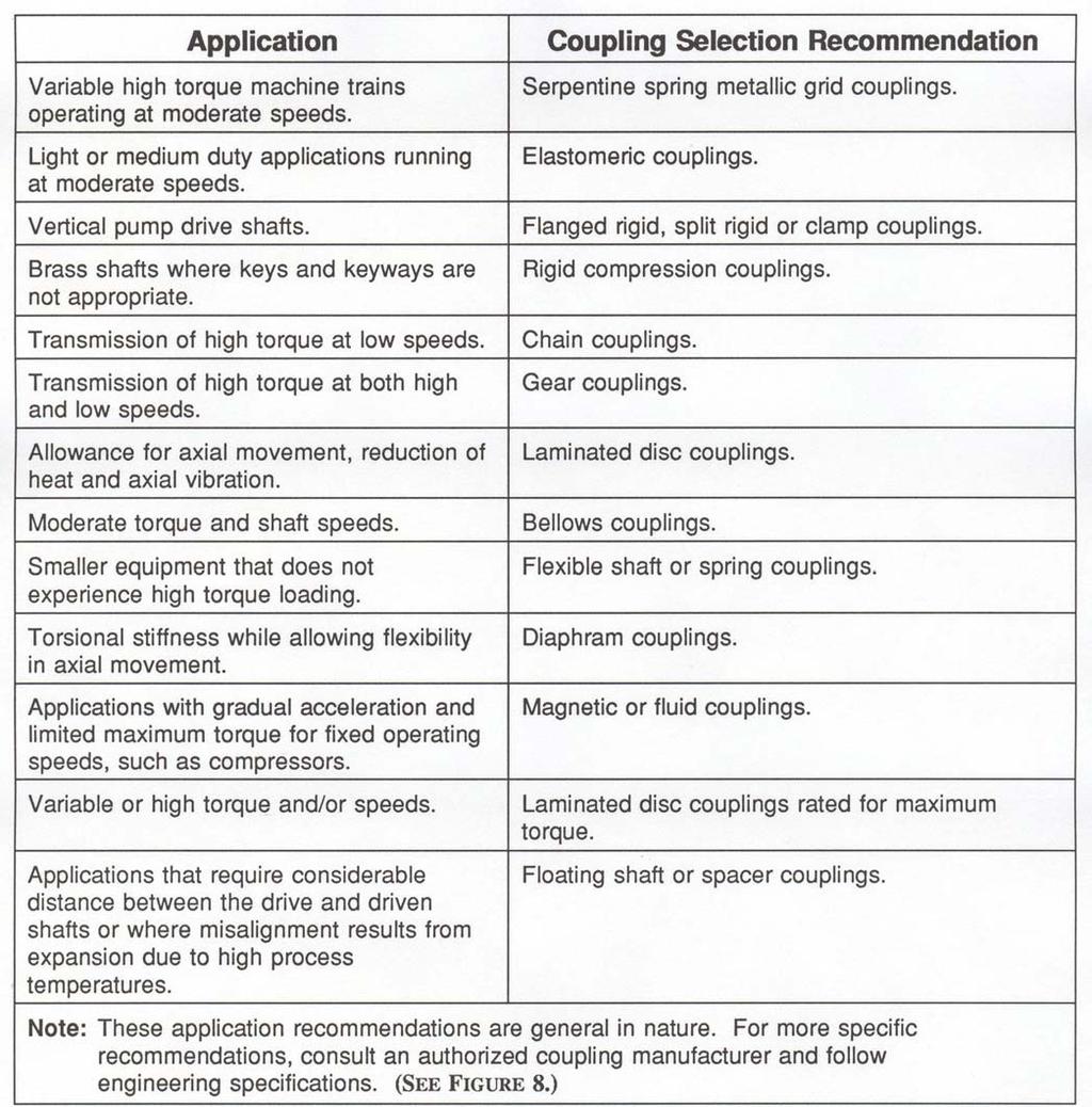
8 3 TABLE 1.

9 FIGURE 8. Some manufacturers like Falk, provide a coupling selector guide that carries the service factor for various equipment types and provides corresponding coupling recommendations. 2. The alignment factor. There is a perception that flexible couplings can accommodate a great deal of parallel offset and/or angular shaft misalignment. This is untrue. Depending upon the coupling type, flexible couplings can only accommodate from ¼ to about 2 ½ degrees of misalignment and high speed, high load drive applications must be aligned to much closer tolerances. (SEE FIGURE 9.) 4
, Process fluid")
10 FIGURE 9. Types of Misalignment Symptoms of misalignment include; Noise at the coupling, Powdered rubber particles or leaking lubricant directly below the coupling (depending upon coupling type), Process fluid and/or oil leaks at the drive, driven (or both) shafts, Premature shaft, shaft keyway, or key fatigue or breakage, Premature or frequent bearing or seal failure at one or both machines, Soft Foot condition at foot bolts, Broken or constantly loosening of foot bolts at one or both machines, Shimmering of oil on base plates, or near the foot bolts, High operating temperatures at or near the coupling, 5
11 High vibration conditions, usually at both machines, Cracked or broken foundation, particularly at or near the foot bolts, Continuing or intermittent leaks at pipe joints caused by pipe strain, High energy consumption, No compensation for thermal growth at either drive or driven machine during initial alignment procedure, Settling of machine or foundation after installation. The following chart lists acceptable misalignment tolerances based on machine speed. (SEE FIGURE 10.) TABLE 2. Allowable Misalignment Tolerances Machine Speed RPM Parallel Offset Misalignment (in MILS) Angular Misalignment (in MILS) < >

12 FIGURE 10. Gear coupling with spacer undergoing laser alignment. The coupling connects an electric motor driving a hammer mill. Fluid couplings are referred to as special purpose, however they are also rigid and cannot accommodate misalignment. (SEE FIGURE 11.) 1
 of the other flange.")
13 FIGURE 11. Fluid coupling undergoing a laser alignment procedure. Alignment can also be determined initially with a dial indicator. To determine parallel offset, mount the indicator on one hub with the point touching the outside diameter (OD) of the other flange. Rotate the hub on which the indicator is mounted while holding the other flange stationary. The parallel misalignment can be determined by obtaining the minimum and maximum readings and dividing by two. (Rotating the flange under the indicator point will not produce a measure of parallel offset). To determine angular misalignment, move the dial indicator point so that it is touching the face of the other hub. Again rotate the hub on which the indicator is mounted while holding the other stationary. 2
14 Again note the minimum and maximum readings. Each inch difference between the two readings for each inch the indicator point is located from the centerline of the shaft indicates an angular misalignment of about one (1) degree. Another issue that may affect alignment is end float or axial shaft movement. There is a tendency for shafts to be pulled closer to their own machine as soon as they are started. As shafts tend to separate at startup, axial end float tries to pull the coupling apart and allowable end float should not exceed ¼ inch. 1. The lubrication factor. There are three flexible coupling types that require lubrication. These are gear and chain mechanically flexible couplings and combination mechanical and material flexible grid couplings. The lubricants used for gear and grid couplings may include; ISO 460 compounded oils with tackiness additives for low speeds and centrifugal G forces of up to 8000 or ISO 100 rust and oxidation inhibited anti-wear oils for high speeds, centrifugal G forces of over 8000 and low temperatures of -20 C (-4 F). NLGI Grades 1 and 2 coupling greases containing high viscosity oil fortified with rust and oxidation inhibitors, extreme pressure additives and tackiness agents to prevent separation at high speeds and high centrifugal G forces, may be recommended for gear, chain and grid type couplings. Note: Centrifugal Force G may be calculated from the equation: G = 14.2 X 10 6 dn2 Where d = pitch diameter of the coupling in inches And N = revolutions per minute. 3
15 Generally, oil or grease can be used at coupling speeds of 3600 to 6000 rpm. Oil is recommended where coupling speeds exceed 6000 rpm. Gear and grid style couplings incorporate seals or gaskets to contain the lubricant and prevent the entry of foreign material. These units contain access plugs for relubrication which must be properly torqued after re-lubrication to ensure that centrifugal force does not loosen the plugs and cause a serious safety hazard. Re-lubrication and inspection intervals should be considered as preventive maintenance tasks and carried out at least annually, (or more frequently, if conditions such as high temperatures call for shorter intervals). The amount of lubricant used is also important. Gear couplings, if overfilled with lubricant, may lockup and the coupling will no longer maintain its flexibility. (Any increase in vibration of the coupling after re-lubrication suggests excessive lubricant). If a coupling is disassembled for re-lubrication, ensure that the two flange halves are marked for correct reassembly and be certain to use specified coupling flange bolts properly torqued. Install new seals or gaskets if the old seals and gaskets have any damage, nicks or are no longer pliable. Before reassembly of grid type couplings, carefully inspect the serpentine spring for damage, wear or fatigue cracks and inspect the grid grooves for excessive wear or evidence of fatigue. On chain and gear type couplings, inspect the chain, sprocket and gear teeth for looseness, wear and evidence of fatigue. (SEE FIGURE 12.) 4

16 FIGURE 12. Courtesy American Axle & Manufacturing. Coupling shows failed serpentine spring and grease residue that had undergone oxidation. The old lubricant removed from the coupling should also be inspected for metal particles indicating wear and darkening in colour suggesting oxidation. Finally, after re-lubrication and re-installation, ensure that safety guards or mesh screens are reinstalled and secured. 2. The operational and environmental factors. Operating conditions and environmental considerations play a large role in the long life and reliability of flexible couplings. Operating temperatures will affect not only the lubricant, but can seriously shorten the life of the materials used in elastomeric couplings. Generally, seals and coupling components cannot withstand temperatures much above 104 C (220 F) and group I mineral base oil begins to oxidize at 71 C (160 F). These guidelines should be understood and applied by machinery operators and as a result, when high operating temperatures and/or where zero back lash is required, flexible disc couplings are recommended over elastomeric types. 5

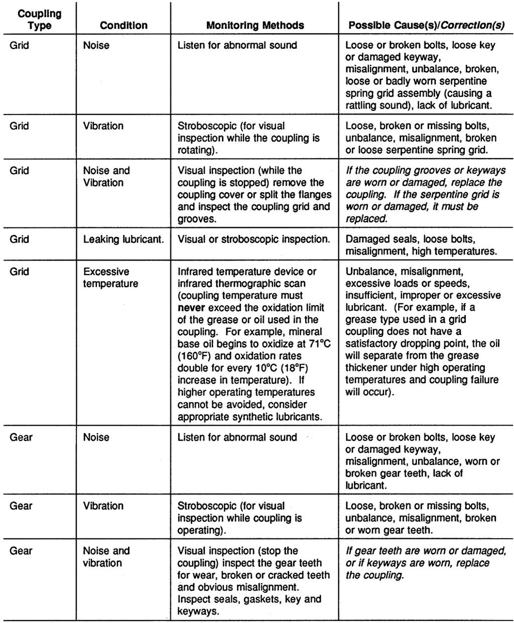
17 In addition, solvents, caustic process fluids and water washing practices may be harmful to some elastomeric couplings and disc, grid or gear couplings may be required. Wherever high loads and speeds are required, disc and gear couplings may be the best choice. Finally, if high temperatures are being experienced, remember that an angular misalignment of as little as inches can increase adjacent bearing temperatures by as much as 18 C (65 F). The lesson is that coupling operating conditions and environment, lubrication and alignment are all related. (SEE TABLE 3.) TABLE 3. 6
18 7
19 8
20 These troubleshooting guidelines are general in nature and cover only those very common flexible couplings described in the guide. For uniquely designed or 9
21 special purpose couplings, contact the appropriate manufacturer for selection, maintenance and troubleshooting recommendations. Conclusion Troubleshooting coupling problems is quite simple, so long as the troubleshooter understands coupling design and application limitations and remembers that reliable machine trains are dependent upon the couplings that connect drive to driven equipment. R e f e r e n c e s Condition Monitoring Standards, Volume 1, IDCON Inc. 2001, PP Industrial Machinery Repair, R. Smith and K. Mobley, 2003, Butterworth- Heinemann, PP Power Transmission Handbook, 4 th Edition, Power Transmission Distributors Association, 2006, PP Coupling Standards, American Gear Manufacturers Association, AGMA 9000, 9001, 9002, 9003, 9004, 9008, The Practical Handbook of Machinery Lubrication, 3 rd Edition, L. Leugner, PP ,
lea) shows a compression type. These couplings are used for
 shows a compression type. These couplings are used for") Mechanical Equipment - Course 230.1 SHAFT COUPLINGS Couplings Couplings are used to join two shafts provide some means of transmitting power source to a driven member. There are two tiona of couplings,
Mechanical Equipment - Course 230.1 SHAFT COUPLINGS Couplings Couplings are used to join two shafts provide some means of transmitting power source to a driven member. There are two tiona of couplings,
Introduction. Lubrication Related Failures. Gear Couplings. Failure Analysis All Types (Page 1 of 7)
") All Types (Page 1 of 7) Introduction A gear coupling serves as a mechanical device which connects shafts of two separate machines and accommodates small amounts of shaft misalignment. Commercial gear couplings
All Types (Page 1 of 7) Introduction A gear coupling serves as a mechanical device which connects shafts of two separate machines and accommodates small amounts of shaft misalignment. Commercial gear couplings
LUBE FITTINGS Cover halves have 3/8 NPT Iube holes. Use a standard grease gun and Iube fitting as instructed on Page 4.
 Falk Steelflex Couplings Installation & Maintenance Type T10 Sizes 1150 1260 & 150 260 (Page 1 of 6) How To Use This Manual This manual provides detailed instructions on maintenance, lubrication, installation,
Installation and Maintenance Instructions Falk Wrapflex (Page 1 of 7) 1. General Information. 2. Safety and Advice Hints DANGER! Type 10R.
 1. General Information. 2. Safety and Advice Hints DANGER! Type 10R.") (Page 1 of 7) This is the Original Document in English Language Type 10R Type 31R Type 35R Figure 1 - Wrapflex coupling range 1. General Information 1.1. Falk Wrapflex Couplings are designed to provide
(Page 1 of 7) This is the Original Document in English Language Type 10R Type 31R Type 35R Figure 1 - Wrapflex coupling range 1. General Information 1.1. Falk Wrapflex Couplings are designed to provide
Amerigear SL Spindle
 Amerigear SL Spindle Installation and Maintenance Manual Form No. 378-SH, 6/97 Spindle Installation and Maintenance Manual TABLE OF CONTENTS SECTION TITLE PAGE 1 Introduction...: 3 2 General Information...:
SKF Flex Coupling Installation Instructions
 SKF Flex Coupling Installation Instructions The performance of the coupling depends largely upon how you install and maintain. 1. Thoroughly clean all components, paying particular attention to the removal
IDENTIFYING DISC COUPLING FAILURES COUPLING FUNDAMENTALS
 IDENTIFYING DISC COUPLING FAILURES While couplings are designed for infinite life, they must be operated within their intended design limits in order to achieve optimal performance. Due to installation
The Lubrication Requirements of Couplings
 The Lubrication Requirements of Couplings Adam M. Davis, Noria Corporation In an ideal world, multiple components could be produced in a single piece, or coupled and installed in perfect alignment. However,
Thomas Disc Couplings Installation and Maintenance Series 52 Sizes with classical disc pack TM (Page 1 of 10) DANGER!
 DANGER!") Thomas Disc Couplings Installation and Maintenance Series 52 Sizes 125-925 with classical disc pack TM (Page 1 of 10) This is the Original Document in English Language Figure 1-1. General Information Thomas
Thomas Disc Couplings Installation and Maintenance Series 52 Sizes 125-925 with classical disc pack TM (Page 1 of 10) This is the Original Document in English Language Figure 1-1. General Information Thomas
GRUNDFOS WHITE PAPER. When considering the overall pumping. COUPLINGS by Greg Towsley
 GRUNDFOS WHITE PAPER COUPLINGS by Greg Towsley When considering the overall pumping system, the shaft coupling is not usually thought of as an important element in the system. Improper selection and maintenance
Contents. SKF Grid Couplings Selection... 34
 SKF Couplings Contents The SKF brand now stands for more than ever before, and means more to you as a valued customer. While SKF maintains its leadership as a high-quality bearing manufacturer throughout
The Importance of Shaft Alignment
 The Importance of Shaft Alignment by John Piotrowski The most frequently asked questions by managers, engineers, foremen, contractors, and trades people concerning the subject of shaft (mis)alignment and
EXPANSION JOINT SELECTION GUIDE
 EXPANSION JOINT SELECTION GUIDE The proper selection and application of an expansion joint is the determining factor in its operation and life. Improper selection and application will lead to problems
Amerigear SF Spindle
 Amerigear SF Spindle Installation and Maintenance Manual Form No. 381-SH, 4/01 Spindle Installation and Maintenance Manual TABLE OF CONTENTS SECTION TITLE PAGE 1 Introduction...: 3 2 General Information...:
PRECISION BELLOWS COUPLINGS
 PRECISION BELLOWS COUPLINGS Bellows couplings are used where precise rotation, high speeds, and dynamic motion must be transmitted. They exhibit zero backlash and a high level of torsional stiffness, offering
We can get more favorable convenience and cost down by using the WCC Taper Grid Steel Flexible Coupling.
 We can get more favorable convenience and cost down by using the WCC Taper Grid Steel Flexible Coupling. 1) PARALLEL The movement of the grid in the lubricated grooves accommodates parallel misalignment
Disc Couplings DI Style (6-Bolt) Installation Guide
 Installation Guide") Disc Couplings DI Style (6-Bolt) Installation Guide 1.0 INTRODUCTION: The following document is intended for the explicit use of Lovejoy customers to aid in the installation of Lovejoy power transmission
Disc Couplings DI Style (6-Bolt) Installation Guide 1.0 INTRODUCTION: The following document is intended for the explicit use of Lovejoy customers to aid in the installation of Lovejoy power transmission
TECHNICAL SERVICE MANUAL
 TECHNICAL SERVICE MANUAL HEAVY-DUTY bracket mounted PUMPS SERIES 4193 AND 493 SIZES GG - AL SECTION TSM 154 PAGE 1 of 10 ISSUE C CONTENTS Introduction....................... 1 Special Information...................
PO Box 645, Stockton, Missouri, FAX superiorgearbox.com
 I000-7000-D0447-A 4/7/05 1 SAFETY PRECAUTIONS CAUTION Please read this entire document prior to operating the gear drive. Gear drive failure and / or injury to operators may be caused by improper installation,
Installation,Operation, and Lubrication Instructions SPEED REDUCERS ILDE-00 TYPE DE ENGINEERING SERVICE BULLETIN
 ENGINEERING SERVICE BULLETIN ILDE-00 D-90 TYPE DE SPEED REDUCERS Installation,Operation, and Lubrication Instructions This Engineering Service Bulletin is designed to enable users to obtain the best possible
GatesFacts Technical Information Library Gates Compass Power Transmission CD-ROM version 1.2 The Gates Rubber Company Denver, Colorado USA
 PREVENTING DRIVE BELT ALIGNMENT PROBLEMS Dan Parsons Plant Engineering July, 1993 Amount of angular and parallel misalignment determines what action to take. Misalignment is one of the most common causes
PERFORMANCE THROUGH REVOLUTION
 PERFORMANCE THROUGH REVOLUTION Dynamatic has a complete range of gear pumps for both mobile and industrial market segments. Dynamatic developed these pumps in technical collaboration with DOWTY Hydraulic
This file is available for free download at
 This file is available for free download at http://www.iluvmyrx7.com This file is fully text-searchable select Edit and Find and type in what you re looking for. This file is intended more for online viewing
Marine Engineering Exam Resource Review of Couplings
 1. What are rigid couplings used for? Used to join drive shafts together. True alignment and rigidity are required. Example Drive shafts and production lines, bridge cranes, solid shaft that needs to be
Maintenance Instructions. World Leader in Modular Torque Limiters. JSE AEA Extruder Clutch
 World Leader in Modular Torque Limiters PROTECTING EQUIPMENT& MACHINERYYEARSInstallation and Maintenance Instructions JSE.5-0234AEA Extruder Clutch 1304 Twin Oaks Street Wichita Falls, Texas 76302 (940)
INSTRUCTION MANUAL FOR DODGE GRID-LIGN FLEXIBLE COUPLINGS
 INSTRUCTION MANUAL FOR DODGE GRID-LIGN FLEXIBLE COUPLINGS Sizes 1020-1140 T10 (Close Coupled, Horizontally Split Cover) T20 (Close coupled, Vertically Split Covers) T31 (Full Spacer ) T35 (Half Spacer
INSTRUCTION MANUAL AND PARTS LIST FOR PG/RG3D_-187, 218, 250 and 312 SERIES PUMPS
 INSTRUCTION MANUAL AND PARTS LIST FOR PG/RG3D_-187, 218, 250 and 312 SERIES PUMPS WARNING This Instruction Manual and General Instructions Manual, CA-1, should be read thoroughly prior to pump installation,
TECHNICAL SERVICE MANUAL
 Electronic copies of the most current TSM issue can be found on the Viking Pump website at www.vikingpump.com TECHNICAL SERVICE MANUAL HEAVY-DUTY Stainless steel BRACKET MOUNTED PUMPS SERIES 127 AND 4127
Maintenance Instructions
 General Note These instructions contain information common to more than one model of Bevel Gear Drive. To simplify reading, similar models have been grouped as follows: GROUP 1 Models 11, 0, 1,, (illustrated),,
SERIES PC INSTRUCTION AND OPERATION MANUAL
 MEGGA SERIES PC INSTRUCTION AND OPERATION MANUAL Models PCT and PCF Close-coupled and frame-mounted single-stage horizontal end-suction pumps. WARNING: Read this manual before installing or operating this
GatesFacts Technical Information Library Gates Compass Power Transmission CD-ROM version 1.2 The Gates Rubber Company Denver, Colorado USA
 MAKING THE RIGHT SHAFT CONNECTIONS Daniel Schwartz & Gary Porter Power Transmission Design August, 1996 Securing a belt pulley to a drive shaft often seems like such a routine task, that engineers and
Type A10. Falk Freedom Disc Couplings Installation and Maintenance. Type A10 Sizes 85 thru 8770 (Page 1 of 5)
") Falk Freedom Disc Couplings Installation and Maintenance Type A0 Sizes 8 thru 8770 (Page of ) How To Use This Manual This manual provides detailed instructions on installation, annual maintenance and parts
Falk Freedom Disc Couplings Installation and Maintenance Type A0 Sizes 8 thru 8770 (Page of ) How To Use This Manual This manual provides detailed instructions on installation, annual maintenance and parts
TECHNICAL INFORMATION
 General Nomenclature Spherical Roller Bearings The spherical roller bearing is a combination radial and thrust bearing designed for taking misalignment under load When loads are heavy, alignment of housings
Models FW, FWO & FWW 403 thru 1018
 BULLETIN 2332 P-222-28 Installation Instructions Overrunning Clutch Couplings Models FW, FWO & FWW 403 thru 1018 23601 Hoover Road - Warren, MI 48089-3994 - 586-758-5000 www.formsprag.com Introduction
HORSTMAN GREASED LIGHTNING CLUTCH
 HORSTMAN GREASED LIGHTNING CLUTCH Horstman s Greased Lightning (GL) clutch is designed for ultra high performance, and requires expert setup and a serious commitment to maintenance. Warning!!! 1. Clutch
OIL CAPACITIES FOR SERIES HP APPROXIMATE CAPACITIES IN QUARTS AND GALLONS
 OIL CAPACITIES FOR SERIES HP APPROXIMATE CAPACITIES IN QUARTS AND GALLONS SINGLE REDUCTION REDUCERS - FLOOR MOUNTED POSITION UNIT SIZE 0 5 0 5 0 50 60 80 00 0 WORM OVER GEAR WORM UNDER GEAR VERTICAL OUTPUT
LUBRICATION, INSTALLATION, OPERATION & MAINTENANCE INSTRUCTIONS FOR STAINLESS STEEL CONE DRIVE SPEED REDUCERS
 LUBRICATION, INSTALLATION, OPERATION & MAINTENANCE INSTRUCTIONS FOR STAINLESS STEEL CONE DRIVE SPEED REDUCERS Cone Drive double-enveloping worm gear speed reducers are used throughout industry to provide
INSTALLATION AND OPERATIING INSTRUCTIONS FOR R+W FLEXIBLE GEAR COUPLINGS BZ / BZA
 INSTALLATION AND OPERATIING INSTRUCTIONS FOR R+W FLEXIBLE GEAR COUPLINGS BZ / BZA GENERAL INFORMATION Please carefully and completely read the following installation, operation and maintenance procedures
Installation and Maintenance Instructions JSE MAEAD Extruder Clutch. World Leader in Modular Torque Limiters
 World Leader in Modular Torque Limiters Installation and Maintenance Instructions JSE.5-0104MAEAD Extruder Clutch 1304 Twin Oaks Street Wichita Falls, Texas 76302 (940) 723-7800 Fax: (940) 723-7888 E-mail:
INSTALLATION, OPERATION AND MAINTENANCE INSTRUCTIONS
 INSTALLATION, OPERATION AND MAINTENANCE INSTRUCTIONS Contents Section 1. General Observations... 2 2. Operation... 4 3. Control During Operation... 5 4. Trouble Shooting... 6 5. Maintenance... 7 Please
Installation and Maintenance Instructions JSE1-0128MAEAD Extruder Clutch. World Leader in Modular Torque Limiters
 World Leader in Modular Torque Limiters Installation and Maintenance Instructions JSE1-0128MAEAD Extruder Clutch 1304 Twin Oaks Street Wichita Falls, Texas 76302 (940) 723-7800 Fax: (940) 723-7888 E-mail:
Why Choose Rexnord? 866-REXNORD/ (Within the U.S.) (Outside the U.S.)
 (Outside the U.S.)") 866-REXNORD/866-739-6673 (Within the U.S.) 44-643-366 (Outside the U.S.) www.rexnord.com Why Choose Rexnord? When it comes to providing highly engineered products that improve productivity and efficiency
866-REXNORD/866-739-6673 (Within the U.S.) 44-643-366 (Outside the U.S.) www.rexnord.com Why Choose Rexnord? When it comes to providing highly engineered products that improve productivity and efficiency
REASONS YOUR BEARINGS WILL FAIL. Ritbearing CORPORATION
 12 REASONS YOUR BEARINGS WILL FAIL Ritbearing Things break. No matter what you do, there is always a chance that products you own will fail. The same holds true for bearings, but that doesn t mean that
CHASSIS CONTENTS EXTERIOR PARTS 6-1 FRAME COVER 6-2 REAR FRAME COVER 6-4 FRONT WHEEL 6-6 FRONT BRAKE 6-10 HANDLEBARS 6-17 FRONT FORK 6-19
 CHASSIS CONTENTS EXTERIOR PARTS 6- FRAME COVER 6- REAR FRAME COVER 6-4 FRONT WHEEL 6-6 FRONT BRAKE 6-0 HANDLEBARS 6-7 FRONT FORK 6-9 STEERING 6-6 REAR WHEEL 6-3 REAR BRAKE 6-39 6 REAR SHOCK ABSORBER 6-43
(d) Bore Size Check from Dimensions table (page 112) that chosen flanges can accommodate required bores.
 Bore Size Check from Dimensions table (page 112) that chosen flanges can accommodate required bores.") Fenaflex Couplings The Fenaflex coupling is a highly flexible, torsionally elastic coupling offering versatility to designers and engineers with a choice of flange combinations to suit most applications.
Fenaflex Couplings The Fenaflex coupling is a highly flexible, torsionally elastic coupling offering versatility to designers and engineers with a choice of flange combinations to suit most applications.
Service Manual #67. Installation and Service Instructions 6000, 7000 & 8000 Series Magnetically Coupled Pumps
 Service Manual #67 Installation and Service Instructions 6000, 7000 & 8000 Series Magnetically Coupled Pumps Table of Contents Section Description Page 1 General Description 4 2 The Pumping Principle 5
Power Transmission Belt Drive System Installation, Maintenance and Troubleshooting Guide
 Power Transmission Drive System Installation, Maintenance and Troubleshooting Guide www.contitech.us Table of Contents Installation Guide 2 Table of Contents Installation V-s V-s 3 Banded s Torque Team
INSTRUCTION MANUAL INTERNAL GEAR PUMP TITAN G-4124A SERIES=> FLANGED TITAN G-124A SERIES => FLANGED MODELS:
 INSTRUCTION MANUAL INTERNAL GEAR PUMP TITAN G-4124A SERIES=> FLANGED TITAN G-124A SERIES => FLANGED MODELS: G-H, G-HL, G-K, G-KK, G-L, G-LQ, G-LL, GLS, G-Q, G-QS 1 Contents Maintenance Thrust bearing adjustment
CHASSIS CONTENTS EXTERIOR PARTS 6-1 FRONT WHEEL 6-2 FRONT BRAKE 6-6 HANDLEBARS 6-12 REAR WHEEL 6-30 REAR BRAKE 6-34 REAR SHOCK ABSORBER 6-36
 CHASSIS CONTENTS EXTERIOR PARTS 6-1 FRONT WHEEL 6-2 FRONT BRAKE 6-6 HANDLEBARS 6-12 FRONT FORK ( ) 6-14 FRONT FORK ( ) 6-20 STEERING 6-27 REAR WHEEL 6-30 REAR BRAKE 6-34 REAR SHOCK ABSORBER 6-36 6 SWING
Installation and Maintenance Instructions JSE2-0241MAEAD Extruder Clutch. World Leader in Modular Torque Limiters
 World Leader in Modular Torque Limiters Installation and Maintenance Instructions JSE2-0241MAEAD Extruder Clutch 1304 Twin Oaks Street Wichita Falls, Texas 76302 (940) 723-7800 Fax: (940) 723-7888 E-mail:
Locking Assemblies Shrink Discs Rigid Couplings.
 M I N I Locking Assemblies Shrink Discs Rigid Couplings www.mav.it our company We are an Italian company world renowned for our creativity and ethics. Established in 1989 we have rapidly built a reputation
Geareducer model 2700 and 3000
 USER MANUAL Geareducer model 2700 and 3000 INSTALLATION - OPERATION - MAINTENANCE M02-128C ISSUED 04/2013 READ AND UNDERSTAND THIS MANUAL PRIOR TO OPERATING OR SERVICING THIS PRODUCT. maintenance schedule
MAINTENANCE MANUAL DP-265
 MAINTENANCE MANUAL DP-265 Drive Gears Sisu Axles, Inc. Autotehtaantie 1 P.O. Box 189 FIN-13101 Hämeenlinna Finland Phone int + 358 204 55 2999 Fax int + 358 204 55 2900 DP265DG.PDF (2/2003) k Table of
AUTOFLEX DISC COUPLINGS
 AUTOFLEX DISC COUPLINGS Contents & Coupling Application Configurations Coupling Type Typical Application Series Page No Introduction - Disc Configuration 2 Coupling Selection 3 & 4 Service Factors High
The gear boxes can be run at the same speeds as the actuator models. Do not exceed torque ratings.
 1. What is the lifting torque required? The lifting torque for a single actuator depends on the load, the worm gear ratio, type of screw (machine cut or ball screw) and the pitch of the lifting screw.
 DRUM BRAKE RIMS Periodic inspection of drum brake rims is necessary to determine indications of uneven or excessive wear. In general, brake rim failures other that regular wear are caused by brake linings
SPECIFICATION/HOW TO ORDER/NOMENCLATURE
 SPECIFICATION/HOW TO ORER/NOMENCLATURE PARA-FLEX SPECIFICATION PARA-FLEX s employ a molded, non-lubricated elastomeric flexing member loaded in shear. The flexible member is compounded natural or neoprene
Installation and Parts Replacement Manual For No. 188D BIO-DISC Reducer
 Installation and Parts Replacement Manual For No. 88D BIO-DISC Reducer These instructions must be read thoroughly before installation or operation. This instruction manual was accurate at the time of printing.
ISO INTERNATIONAL STANDARD
 INTERNATIONAL STANDARD ISO 14691 First edition 1999-11-01 Petroleum and natural gas industries Flexible couplings for mechanical power transmission General purpose applications Industries du pétrole et
Failures of Rolling Bearings in Bar and Rod Mill
 Case Study Failures of Rolling Bearings in Bar and Rod Mill by Christo Iliev University of Zimbabwe, Dept. of Mechanical Engineering Harare, Zimbabwe INTRODUCTION Bar and rod mills can usually be found
Shaft Couplings Tru-Line Flange-Couplings Rigid Shaft Couplings Flexible Couplings
 Shaft Couplings Tru-Line Flange-Couplings Rigid Shaft Couplings Flexible Couplings Edition 2015/2016 RINGSPANN Registered Trademark of RINGSPANN GmbH, Bad Homburg Table of Contents Tru-Line Flange-Couplings
CLUTCH CONTENTS SERVICE DIAGNOSIS. (a) Worn or damaged disc assembly. (b) Grease or oil on disc facings. (c) Improperly adjusted cover assembly.
 Worn or damaged disc assembly. (b) Grease or oil on disc facings. (c) Improperly adjusted cover assembly.") CLUTCH CONTENTS -GROUP 6 Page CLUTCH HOUSING ALIGNMENT... 6 CLUTCH PEDAL FREE PLAY 1 CLUTCH RELEASE BEARING 5 CLUTCH RELEASE FORK... 5 CLUTCH SERVICING 2 PILOT BUSHING CRANKSHAFT TO TRANSMISSION DRIVE
CLUTCH CONTENTS -GROUP 6 Page CLUTCH HOUSING ALIGNMENT... 6 CLUTCH PEDAL FREE PLAY 1 CLUTCH RELEASE BEARING 5 CLUTCH RELEASE FORK... 5 CLUTCH SERVICING 2 PILOT BUSHING CRANKSHAFT TO TRANSMISSION DRIVE
Northern Pump A Division of McNally Industries, LLC
 Operation & Maintenance Manual for Northern 4900 Injection Operation & Maintenance Manual For Northern 4900 Injection Northern Pump A Division of McNally Industries, LLC 340 West Benson Avenue Grantsburg,
High Performance Gear
 JW High Performance Gear In This Section: FHS Type - High Speed Close Coupled FHSA Type - High Speed Standard FHSAA Type - High Speed Precision FHSPAA Type - High Speed Ultra Precision FHSMA Type - High
INSTALLATION AND HANDLING
 SHAFT / AXIS MISALIGNMENT Exact alignment of the shaft axes extends the service life of the coupling and adjacent components by minimizing reaction loads from misalignment. FIT CLEARANCE Overall shaft
SCREW JACK POWER TRANSMISSION COMPONENTS TYPICAL SYSTEM ARRANGEMENTS
 TYPICAL SYSTEM ARRANGEMENTS Duff-Norton offers all of the components necessary to complete your power transmission system, whether it consists of a single actuator or a multiple actuator arrangement. We
WARNING DO NOT USE THE PRODUCTS IN THIS GUIDE IN AIRCRAFT APPLICATIONS. THE PRODUCTS IN THIS GUIDE ARE NOT INTENDED FOR USE IN AIRCRAFT APPLICATIONS.
 P O W E R T R A N S M I S S I O N P R O D U C T S power transmission belt drive system Installation, Maintenance and Troubleshooting Guide WARNING DO NOT USE THE PRODUCTS IN THIS GUIDE IN AIRCRAFT APPLICATIONS.
FHB 8110 Brake Assemblies Installation, Operation and Maintenance Manual Airflex
 FHB 8110 Brake Assemblies Installation, Operation and Maintenance Manual Airflex General Information Forward this manual to the person responsible for Installation, Operation and Maintenance of the product
HOR Series Mechanical Overload Release Clutches
 HOR Series Mechanical Overload Release Clutches P-328-BG Installation & Maintenance Instructions HOR Series Model H16 Contents I. Operating Principle...2 Il. Mounting Adapters and Sprockets or Sheaves
Shaft Couplings Flange-Couplings Rigid Shaft Couplings Flexible Couplings
 Shaft Couplings Flange-Couplings Rigid Shaft Couplings Flexible Couplings 44 Edition 2013/2014 RINGSPANN Registered Trademark of RINGSPANN GmbH, Bad Homburg 2 Table of Contents Flange-Couplings Page Flange-Couplings
Flexible Couplings 44
 Flexible Couplings 44 RINGSPANN Registered Trademark of RINGSPANN GmbH, Bad Homburg MTY (81) 83 54 10 18 Why RINGSPANN Flexible Couplings? No connection of shafts without clutches It is a well-known fact
Installation and Operational Instructions for EAS -Compact overload clutch, Type 49_. 4._ Sizes 4 and 5
 Please read these Operational Instructions carefully and follow them accordingly! Ignoring these Instructions may lead to malfunctions or to clutch failure, resulting in damage to other parts. Contents:
PR Series Positive Rotary Pumps
 PRSM PR Series Positive Rotary Pumps Models PR, PRE, and PRED CONTENTS Thank you for purchasing a Tri-Clover Product! This manual contains disassembly and assembly instructions, maintenance procedures,
COUPLERS 5. Fax: +44 (0)
") COUPLERS Fax: +44 (0)1992 09890 3 COMPOSITE JAW COUPLERS (SERIES FS) L1 2.0 mm Max L2 2.0 mm Max L3 Bore B s 032-037 s 02-08 max features Low mass Freedom from corrosion Good damping properties Low cost
COUPLERS Fax: +44 (0)1992 09890 3 COMPOSITE JAW COUPLERS (SERIES FS) L1 2.0 mm Max L2 2.0 mm Max L3 Bore B s 032-037 s 02-08 max features Low mass Freedom from corrosion Good damping properties Low cost
Pulley Alignment. Parallel Misalignment
 Pulley Alignment There are many different factors that contribute to machine downtime when considering Sheave/Pulley, Belt and Bearing wear. The single biggest factor that can impact the reliability of
Fitting-removal and maintenance
 Fitting-removal and maintenance Fitting of bearings 136 General rules 136 Fitting principles 136 Hot fitting 137 Press fitting (or with anti-rebound hammer) 138 Adapter sleeves 139 Removal of bearings
2.- HANDLING OF VALVES BEFORE ASSEMBLY 3.- FITTING THE VALVE TO THE REST OF THE ASSEMBLY 5.- PERIODICAL INSPECTION OF THE VALVE AND MAINTENANCE
 Page 1 of 16 CONTENTS 1.- INTRODUCTION 2.- HANDLING OF VALVES BEFORE ASSEMBLY 3.- FITTING THE VALVE TO THE REST OF THE ASSEMBLY 4.- OPERATION OF A BALL VALVE 5.- PERIODICAL INSPECTION OF THE VALVE AND
CHAPTER 7 FRONT AXLE
 CHAPTER 7 FRONT AXLE 1. STRUCTURE FRONT AXLE 1.1 FRONT AXLE STRUCTURE 704W701A (1) Front Bracket (2) Rear Bracket (3) Center Pin (4) Front Axle Support (5) Bevel Gear Case (6) Front Axle Case (7) Front
Mechanical Equipment - Course 230.1
 Mechanical Equipment - Course 230.1 BELT DRIVES A conunon method of transmitting power is a combination of belts and pulleys, There are many types of belts and pulleys used for the transmission of power
Platinum Series FEATURES: Up to 16 Stainless Steel Plies
 Maximum Vibration Absorption Longest Cycle Life Soft Spring Rate = Ease of Installation Maximum Safety Platinum Series Series 151-1215 Welded Fixed Flange Series 150-TR-2115 Van Stone Floating Flange Keflex
Trends Regarding Rolling Bearings for Steering Systems
 Trends Regarding Rolling Bearings for Steering Systems M. TANIYAMA * *Automotive Engineering Center, Automotive Bearing Engineering Department Many bearings are used in the columns, gears and pumps of
PK couplings. Product description. PK couplings
 Product description The INKOMA-PK coupling is machine component designed to transmit torque between axially parallel, radially offset shafts. The coupling permits both static and dynamic stepless adjustment
Product description. PK couplings
 Product description The INKOMA-PK coupling is machine component designed to transmit torque between axially parallel, radially offset shafts. The coupling permits both static and dynamic stepless adjustment
Chapter 11 Rolling Contact Bearings
 Chapter 11 Rolling Contact Bearings 1 2 Chapter Outline Bearing Types Bearing Life Bearing Load Life at Rated Reliability Bearing Survival: Reliability versus Life Relating Load, Life, and Reliability
Bearings. Rolling-contact Bearings
 Bearings A bearing is a mechanical element that limits relative motion to only the desired motion and at the same time it reduces the frictional resistance to the desired motion. Depending on the design
DIAGNOSIS AND TESTING
 205-02B-1 DIAGNOSIS AND TESTING Rear Drive Axle and Differential Special Tool(s) Dial Indicator Gauge with Holding Fixture 100-002 (TOOL-4201-C) or equivalent 205-02B-1 4 Has the driveline system been
Parts made by people who race and know what it is about
 RACING TRANSMISSIONS / 840 SERIES The 840 series has been one of the best options for front engine-rear wheel drive racing cars with4/6 cylinder engines since 1975; formerly, with the TC models, and at
2002 F-Super Duty /Excursion Workshop Manual
 Page 1 of 5 SECTION 205-02D: Rear Drive Axle/Differential Ford 10.50-Inch Ring Gear 2002 F-Super Duty 250-550/Excursion Workshop Manual DIAGNOSIS AND TESTING Procedure revision date: 02/02/2005 Rear Drive
Instruction and Installation Manual
 Instruction and Installation Manual ROSTA Tensioner Devices Tensioners Accessories -G -W -R Sprocket wheel N Chain rider P Oil resistant Up to + 120 C Reinforced Sprocket wheel set Chain rider set -I -F
OVERLOAD CLUTCHES FOR INDEX DRIVES
 The Driving Force in Automation OVERLOAD CLUTCHES FOR INDEX DRIVES WARNING WARNING This is a controlled document. It is your responsibility to deliver this information to the end user of the CAMCO indexer.
They are mainly used with hydraulic machineries, pumps, blower fans, conveyors, cranes & general power driven industrial equipments.
 www.koreacoupling.co.kr Korea Coupling Co., Ltd., This is a specialist for power transmission equipments manufacturer including shaft couplings and supply high quality products to various industries, such
KTR Torque Limiters Overload Protection Systems
 KT Torque Limiters Overload Protection Systems UFLEX - Friction Disk - Zero Backlash Ball Detent KT SI - Ball/oller Bearing Style KT SI Compact - Zero Backlash Ball Detent Catalog Contents (Metric) Page
Torque Limiter 320 Series Overview. Torque Limiter 320 Series
 Torque Limiter 0 Series Overview Torque Limiter 0 Series Torque Limiter 0 Series For more than 80 years, Autogard products have led the industry in overload protection with high-quality products, design
Boston Gear ORC Series
 Boston Gear ORC Series Trig-O-Matic Overload Release Clutches Installation and Maintenance Instructions Doc. No. ORC Series Model S www.bostongear.com ORC SERIES TRIG-O-MATIC OVERLOAD RELEASE CLUTCHES
SKF Disc Couplings. Selection
 SK Disc Couplings The SK disc coupling is the ideal solution in medium to high applications that require torsional rigidity, offer some allowance for misalignment, and do not require lubrication. These
FLEXIDYNE PH Couplings
 FLEXIDYNE PH s s:,,,,,, D, D, D These instructions must be read thoroughly before installing or operating this product. DESCRIPTION: dry fluid couplings are a unique concept to provide soft start and momentary
Wye Connector. GT Exhaust Accessories Installation and Operation Manual. Rev. A. (c) Copyright 2012, GT Exhaust, Inc. All Rights Reserved
 Copyright 2012, GT Exhaust, Inc. All Rights Reserved") Wye Connector GT Exhaust Accessories Installation and Operation Manual Rev. A (c) Copyright 2012, GT Exhaust, Inc. All Rights Reserved Published: April 30, 2012 NOTICE The instructions herein must be expressly
Wye Connector GT Exhaust Accessories Installation and Operation Manual Rev. A (c) Copyright 2012, GT Exhaust, Inc. All Rights Reserved Published: April 30, 2012 NOTICE The instructions herein must be expressly
PRODUCT OBSOLETED 1Q16
 TECHNICAL SERVICE MANUAL HEAVY DUTY STEEL EXTERNAL MOUNTED PUMPS SERIES 123 AND 4123 SIZES H-LL SECTION TSM 151.1 PAGE 1 OF 13 ISSUE C CONTENTS Introduction 1 Special Information 2 Maintenance 3 Packed
Best Practice Guideline. Tyre Handling in Surface Operations
 Best Practice Guideline Tyre Handling in Surface Operations www.aspasa.co.za June 2018 Introduction The job of tyre servicing can be extremely hazardous. An inflated large vehicle tyre contains tremendous
PROPELLER SHAFT & DIFFERENTIAL CARRIER SECTIONPD CONTENTS
 PROPELLER SHAFT & DIFFERENTIAL CARRIER SECTIONPD CONTENTS PREPARATION...2 PROPELLER SHAFT...5 On-Vehicle Service...6 Removal and Installation...7 Inspection...7 Disassembly...7 Assembly...8 ON-VEHICLE