INSTALLATION INSTRUCTIONS KAWASAKI MULE PRO-FXT
|
|
|
- Rudolf McGee
- 5 years ago
- Views:
Transcription


1 INSTALLATION INSTRUCTIONS
2 SAFETY INSTRUCTIONS Warning: Failure to heed all safety and operating instructions and warnings regarding use of this product can result in serious bodily injury. READ PROPERLY COMPLETE ASSEMBLY INSTRUCTIONS BEFORE STARTING OF ASSEMBLY Install all parts indicated in assembly instructions. Failure to fully assemble product before use could result in personal injury. Assembly of product requires use of hand or power tools. If you are not experienced in using these types of tools, have product dealer do the install for you. Some parts contain sharp edges, wear protective gloves if necessary. Always keep your assembly area clean, uncluttered and well lit. Keep visitors and children a safe distance away from the assembly area. Visitors should wear the same safety equipment described under. 2 Never operate your UTV with the cab doors open. Failure to properly latch the doors before moving the vehicle could result in serious injury. Dress for safety. DO NOT wear loose clothing, gloves, neckties or jewelry if using power tools to assemble this product. Insert all nut covers after you finish installation. Never drive your UTV with the cab front window in open position. Failure to properly latch/lock front window before driving the vehicle could result in serious injury. For safety purposes, if the DFK Cab doors are removed, it is mandatory that the OEM Half Doors or Nets are REINSTALLED before operating vehicle.
3 MAINTENANCE AND CLEANING To clean polycarbonate surface use soapy water solution or other subtle means. Dirt and dust wash by gently water stream and swipe only with wet or damp means in the direction from top to bottom. The recommended frequency of cleaning of polycarbonate part is about 1 time per month or according to the actual degree of pollution. Do not use detergents that could scratch the surface plates. (abrasives, harsh fabrics, etc.) Do not use solvents or alkaline detergents or cleaners with ammonia (ammonium hydroxide). Do not remove the impurities from the surface of the razor blades or other sharp items. Do not clean cabin when the polycarbonate plates are heated by the sun. 3 Do not use the squeegee, it could be scratched surface plates. Do not clean the water current strength greater than 50 bar (WAP) The manufacturer is not responsible for scratching the surface in case of failure to comply with the above instructions. All bolted connections of cab must be by user at regular intervals checked and tightened.

4 PREPARATION FOR INSTALLATION: Uninstall all additional systems from the roller cages (work lights, rear mirrors, drink holders etc.) CAB PREVIEW 4
 by including screws from inner side (next")
5 RIGHT DOOR BASE + LEFT DOOR BASE One by one replace original screws (red circle) by including screws from inner side (next page). 5

6 6

7 Place the right rear door base onto the UTV roller cage. 7

8 One by one replace the screws from the outter side and fix the right rear door base with the UTV roller cage. 8

9 Place the right rear door base holders onto the right rear door base and fix by included screws, washers, nuts and covers. 9

10 Repeat previous steps with the left rear door base. 10
.")
11 One by one replace original screws (red circle) by included screws from inner side (next page). 11

12 12

13 Place the right front door base onto the UTV roller cage. 13

14 One by one replace the screws from the outter side and fix the right front door base with the UTV roller cage. 14

15 Place the right front door base holders onto the right front door base and fix by included screws, washers, nuts and covers. 15

16 Repeat previous steps with the left front door base. 16

17 REAR PANEL Stick the self glued rubber seal onto the rear UTV frame. Make sure that surface of the frame is clean. 17

18 Place the rear assembly onto the the seal. 18

19 Place the rear upper holder onto the rear polycarbonate and fix by included screw, washers, nut and cover. 19

20 Place the rear bottom holder onto the rear polycarbonate and fix by included screw, washers, nut and cover on both sides. 20

21 Place the rear side holders onto the rear polycarbonate and fix by included screws, washers, nuts and covers on both sides. 21
 by included")
22 FRONT PANEL 1. One by one replace the original screws (red circle) by included screws from inner side (next page) on both sides. 22

23 23

24 Place front bottom ledge onto the UTV roller cage. 24

25 One by one replace the screws from the outer side and fix the front bottom ledge with the UTV roller cage on both sides. 25

26 Insert the included front door stop holder screws into the front bottom ledge holder holes. 26

27 Place the front bottom ledge holder with the screws onto the front bottom ledge and fix by included screws, washers, nuts and covers on both sides. 27

28 Place the front upper ledge onto the UTV roller cage. 28

29 Place the front upper ledge side holder onto the front upper ledge and fix by included screw, washer, nut and cover on both sides. 29

30 ROOF Place the front roof panel onto the UTV roller cage. Take extra care if you have model with A/C pre-installed on the front roof panel. 30

31 Place the front upper ledge/roof holders onto the front upper ledge and fix by included screws, washers, nuts and covers. 31

32 Place the front roof holder ledge onto the front roof panel and fix by included screws, washers, nuts and covers. 32

33 Place the roof hinges onto the front roof panel and fix by included screws, nuts and covers. 33

34 Place the rear roof panel onto the UTV roller cage. 34

35 Adjust the rear roof panel into best position and fix the roof hinges with the rear roof panel by included screws, nuts and covers. 35

36 Place the rear roof holder onto the rear roof panel and fix by included screw, washer, nut and cover. 36

37 Install the roof gas spring into the roof gas spring holders and fix by included nut, washers, and cover. 37


38 ELECTROINSTALLATION WIPER SET View onto the wiper motor with the cover and with the middle ledge. 38 Place the washer onto the wiper longer pin.


39 Place the washer onto shorter wiper pin. View onto installed washers. 39


40 Place the wiper assembly onto the front glass from inner side. Insert these washers onto the wiper s pins and onto the glass from outer side. Fix the wiper motor with the front glass by included nuts and tighten these correctly. 40

41 FRONT PANEL 2 Place the front glass assembly onto the front upper ledge by hinges and fix by included screws, washers, nuts and covers. 41

42 Install the front gas spring into the front gas spring holders and fix by included nuts, wahers and covers. 42

43 RIGHT DOOR + LEFT DOOR Place the right rear door stop holder 2 onto the right rear door stop 1 and fix by included screws, washers, nuts and covers. Install the door stop assembly into the right rear door stop holder 1. 43

44 Place the right rear door stop assembly onto the right front door base in accordance with the welded nuts and fix by included screws and washers. 44

45 Place the right frame hinges onto the right rear door base and fix by included screws, washers, nuts and covers. Lubricate the hinges pins and place washers 10 onto the pins. 45
46 Do NOT switch the upper and bottom hinge. 46

47 Place the right rear door onto the hinges. 47

48 Adjust the right rear door into the best position and tighten screws correctly. 48

49 Adjust the right rear door stop assembly into the best position and tighten screws correctly. 49

50 Install the door gas spring into the right rear gas spring holders and fix by included nuts, washers and covers. 50

51 Place the right frame hinges onto the right front door base and fix by included screws, washers, nuts and covers. Lubricate the hinges pins and place the washers 10 onto the pins. 51

52 Install the gas spring assembly into the right front door stop holder. 52

53 Place the right front door stop assembly onto the front bottom ledge holder prepared screws and fix by included nuts, washers and covers. 53

54 Place the front door ledge onto the original door hinges and fix the ledge with the hinges by included screws, washers, nuts and covers. Fix the front door ledge with the front dashboard by included rubber rivet. 54

55 Place the right front door onto the hinges. 55

56 Adjust the right front door into the best position by hinges and tighten screws correctly. 56

57 Adjust the right front door stop assembly into the best position and tighten screws correctly. 57

58 Install the door gas spring into the right front gas spring holders and fix by included nuts, washers and covers. 58

59 Place the right door mirror onto the right mirror holder and fix by included screws, washers, nuts and covers. 59

60 Place the right door mirror assembly onto the right front door and fix by included screws and washers. 60

61 Repeat previous steps with the left doors. 61

62 Place the rear frame lock cover holder onto the rear panel lock cover and fix by included swell action latch. 62

63 Place the rear panel lock cover assembly into the best position and fix with the UTV panel by included rubber rivets. 63

64 Place the fuel tank cover into the best position and fix by included rubber rivets. 64
65 ELECTROINSTALLATION WIPER/WASHER ASSEMBLY Overall wiring diagram (wiper/washer) 65 SEE NEXT PAGES


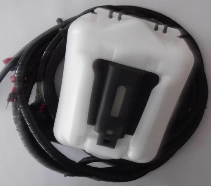
66 Washer tube Parts needed (Included) Switch wiper/washer/off Harness and washer tank 66


67 Install the washer tank to the UTV by washer tank holder and correct screw, washers and nut (included). Run the harness branch No.: 2 from the harness to the dasboard inner space (blue line). 67


68 Find the best place for wiper/washer switch and cut rectangle hole for that. Connect the harness branch No.: 2 with the swith and insert that into the hole. Run the harness branch No.:1 around the roller cage to the wiper motor. 68

.")
69 Connect the harness branch No.:1 with the wiper motor and stretch the washer hose through the bushing. Run the harness branch No.: 4 from the harness to the UTV s main electrification. Find the original cable where is 12V+ after you turn on the main UTV s switch. Connect the harness cables, red to 12V+original electrification and black to UTV s skelet. 69 If you don t find connection for connectors installed on harness branch, you can use other connectors (included). Fill the washer liquide into the washer tank before first usage.


70 Now you can turn on wiper switch and look on the larger wiper pin. If you connect all harness connectors correctly, pin is turning. Find the ends of turning and install the wiper arm on correct position. Fix the wiper arm with the wiper motor pin by included nut. Insert plastic holder onto the wiper latch pin in correct position 70


71 View onto the installed plasstic holder. Insert the wiper arm hook onto the wiper latch plastic holder and press it into the correct position. 71


72 View onto installed wiper arm hook. Connect the washer hose from the harness with the washer hose from wiper arm by included tube. 72
73 ELECTROINSTALLATION HEATER Overall wiring diagram (heater) 73

74 IMPORTANT IT IS ABSOLUTELY NECESSARY TO TAKE OUT THE RUBBER PLUGS FROM THE HEATER TUBES!!! 74
.")

75 Drill necessary holes into the rear glove box cover and lead the hot water hoses and the heater harness through(red circles). 75 Install the hot water pump onto the hot water hose(red circle). Take extra care to the correct orientation. Connect the hot water pump to the pump harness.
 and fix these with the UTV s body by included rubber rivets.")
76 Install the heater holder to best position (heater assembly covers the golve box) and fix these with the UTV s body by included rubber rivets. 76

77 Run the harness branch from the harness to the UTV s main electrification. Find the original cable where is 12V+ after you turn on the main UTV s switch. Connect the harness cables, red to 12V+original electrification and black to UTV s skelet. If you don t find connection for connectors installed on harness branch, you can use other connectors (included). 77


78 Connect hot water hose with the UTV s cooling circuit near the cooler by Y coupling (included). Lead the second hot water hose under the UTV floor to the engine. 78
.")

79 Connect hot water hose with the UTV s cooling circuit near the engine by Y coupling (included). Connect the heater to the hot water hoses and to the heater harness and place the heater onto the heater holder and fix by included nuts, washers and covers on both sides. 79
80 It is absolutely necessary to bleed the air out of the UTV s engine cooling system. Incomplete bleeding of cooling system can result in engine damage. If you don t have sufficient experience with this process, we strongly recommend professional service technician assistance. We are not responsible for damages when cooling system bleeded incompletely. Please note that aditionall heater system will absorbed more than 2 liters of coolant fluid. 1. Important: After the heater system installed check the system for leaks. Turn on the electric vent switch and confirm that the engine is cold. Start the engine, open bleeding valve and wait untill engine warmes up. Important: Allways check engine temperature if it overheats turn of engine. 2. To achieve engine operating temperature depress the accelerator to increase The engine RPM. This will increase the preasure and flow of the water pump forcing more coolant through the heater. After operating temperature ceache turn of engine and open it. Trapped air should come out from heater system throughout bleeding valve. Repeat this procedure until heater/cooling system is completely bleeded out. The DFK Cab heater, like the heater in a car, generates heat from the vehicle s engine. In nearly all cases, the heater should generate enough heat from your UTV, side by side, or tractor engine that you may need to turn the heater off periodically otherwise the air in the cabin may be too hot. 80 It is important to check the coolant level regularly at least 4-5 times during the first several days of operation and fill as necessary until the coolant level has stabilized. The heater will draw and retain coolant, sometimes at the expense of coolant to the engine. This can cause engine overheating if not managed properly.
INSTALLATION INSTRUCTIONS KAWASAKI MULE 610
 INSTALLATION INSTRUCTIONS SAFETY INSTRUCTIONS Warning: Failure to heed all safety and operating instructions and warnings regarding use of this product can result in serious bodily injury. READ PROPERLY
INSTALLATION & OWNER S MANUAL
 Rev. B, p. 1 of 18 INSTALLATION & OWNER S MANUAL KAWASAKI TERYX ClearView Cab p/n: 1KAWT8002CV This cab fits model years: 2014- The contents of this envelope are the property of the owner. Be sure to leave
INSTALLATION & OWNER S MANUAL
 Rev. C, p. 1 of 24 INSTALLATION & OWNER S MANUAL HONDA PIONEER 700-2 ClearView Cab p/n: 1HONP7002CV This cab fits model years up thru 2016. The contents of this envelope are the property of the owner.
INSTALLATION & OWNER S MANUAL
 Rev. D, p. 1 of 29 INSTALLATION & OWNER S MANUAL YAMAHA VIKING YXM 700 ClearView Cab p/n: 1YAMVKCV fits model years up thru 2018 (fits Yanmar Bull model years up thru 2018) The contents of this envelope
INSTALLATION & OWNER S MANUAL
 Rev. C, p. 1 of 24 INSTALLATION & OWNER S MANUAL HONDA PIONEER 700-4 ClearView Cab p/n: 1HONP7004CV fits model years up thru 2017 The contents of this envelope are the property of the owner. Be sure to
SPARE - PARTS CATALOGUE KYMCO 500I, 700I SE
 SPARE - PARTS CATALOGUE KYMCO 500I, 700I SE. CAB PREVIEW 2 3 Position Catalogue no. Description Qty 1 58S01U01S30 ROOF 1 2 58S01U01S21 REAR PANEL 1 3 58S01U01S40 LEFT DOOR 1 4 58S01U01S10 FRONT PANEL 1
SPARE - PARTS CATALOG KAWASAKI MULE 610
 SPARE - PARTS CATALOG KAWASAKI CAB PREVIEW 2 3 Position Catalogue no. Description Qty 1 42S02U01S10 FRONT PANEL MOVABLE 1 2 42S02U01S20 REAR PANEL 1 3 42S02U01S30 ROOF 1 4 42S02U01S40 LEFT DOOR 1 FRONT
Arctic Cat Wildcat Cab kit* Caution: Before using this product, read this manual and follow all safety instructions.
 Owner s Manual Model: Arctic Cat Wildcat Caution: Before using this product, read this manual and follow all safety instructions. Arctic Cat Wildcat Cab kit* Safety Instructions Kit Contents Tool Requirement
SPARE - PARTS CATALOGUE YAMAHA VIKING YXM 700
 SPARE - PARTS CATALOGUE YAMAHA VIKING YXM 700. CAB PREVIEW 2 3 Position Catalogue no. Description Qty 1 41S04U01S30 ROOF 1 2 41S04U01S20 REAR PANEL 1 3 41S04U01S40 LEFT DOOR 1 4 41S04U01S10 FRONT PANEL
SPARE - PARTS CATALOG KAWASAKI MULE PRO-FX(DX)
") SPARE - PARTS CATALOG KAWASAKI CAB PREVIEW 2 3 FRONT PANEL 4 5 6 FRONT UPPER LEDGE HOLDER ASSEMBLY 42S05U01-10M006 7 FRONT UPPER LEDGE SIDE HOLDER ASSEMBLY 42S05U01-10M005 8 FRONT GAS SPRING HOLDER ASSEMBLY
SPARE - PARTS CATALOG KAWASAKI CAB PREVIEW 2 3 FRONT PANEL 4 5 6 FRONT UPPER LEDGE HOLDER ASSEMBLY 42S05U01-10M006 7 FRONT UPPER LEDGE SIDE HOLDER ASSEMBLY 42S05U01-10M005 8 FRONT GAS SPRING HOLDER ASSEMBLY
For Kioti Mechron Caution: Before using this product, read this manual and follow all safety instruction. Defender Cab Owner s Manual.
 ` Defender Cab Owner s Manual Model: Kioti Mechron 2200 Caution: Before using this product, read this manual and follow all safety instruction For Kioti Mechron 2200 Safety Instructions Kit Contents Tool
SPARE PARTS CATALOGUE CUSHMAN 1600 XD R KIOTI MECHRON 2210 LTEC XS 1000
 SPARE PARTS CATALOGUE CUSHMAN 1600 XD R KIOTI MECHRON 2210 LTEC XS 1000. PREVIEW CAB Positio Catalogue no. Description Qty n 1 37S02U01S30 ROOF 1 2 37S02U01S10 FRONT PANEL 1 3 37S02U01S40 LEFT DOOR 1
2011-up Polaris RZR 800* Cab Enclosure Kit. Caution: Before using this product, read this manual and follow all safety instructions.
 Owner s Manual Model: Polaris RZR * 2011-up Polaris RZR 800* Cab Enclosure Kit Caution: Before using this product, read this manual and follow all safety instructions. Safety Instructions Kit Contents
For Honda Big Red. Caution: Before using this product, read this manual and follow all safety instruction. Defender Cab Owner s Manual.
 Defender Cab Owner s Manual Model: Honda Big Red Caution: Before using this product, read this manual and follow all safety instruction For Honda Big Red Safety Instructions Kit Contents Tool Requirement
2008~2010 Polaris RZR 800* Cab Enclosure Kit Slam latch hardware
 Owner s Manual Model: Polaris RZR * 2008~2010 Polaris RZR 800* Cab Enclosure Kit Slam latch hardware Caution: Before using this product, read this manual and follow all safety instructions. Safety Instructions
Assembly Instructions
 Assembly Instructions Part Number Description Model Approx. Assembly Time 99994-0903 Windshield Wiper Kit Mule SX 1 Hour WARNING Improper installation of this accessory could result in an accident causing
Assembly Instructions
 Assembly Instructions Part Number Description Model Approx. Assembly Time 99994-049 Cab Enclosure MULE SX 3-4 Hours WARNING Improper installation of this accessory could result in an accident causing serious
Thank You For Choosing. INSTALLATION INSTRUCTIONS Flip Windshield for Polaris General. Seal. Need help with your installation?
 2753 Michigan Road Madison, Indiana 47250 812-574-7777 INSTALLATION INSTRUCTIONS Flip Windshield for Polaris General A Item Description Qty A Windshield 1 Seal (kit contents continue on following pages)
INSTALLATION & OWNER S MANUAL
 INSTALLATION & OWNER S MANUAL CAB INSTALLATION INSTRUCTIONS JOHN DEERE 3000 SERIES (4200/4300/4400) (4210/4310/4410) & (3120/3320/3520/3720) HARD SIDED CAB ENCLOSURE (p/n 1JD3520AS) SOFT SIDED CAB ENCLOSURE
INSTALLATION & OWNER S MANUAL
 INSTALLATION & OWNER S MANUAL This Curtis Cab is designed and manufactured for use only as reasonable weather protection. This cab is not applicable, Nor should the cab be considered as protection against
NIS NAV AM (MY15 >) - Aluminium Tonneau Cover ATC0051 (silver) ATC0052 (Black) Installation Time: Approx. 60 Minutes WARNING!
 - Aluminium Tonneau Cover ATC0051 (silver) ATC0052 (Black) Installation Time: Approx. 60 Minutes WARNING!") Installation Time: Approx. 60 Minutes WARNING! When in the closed position, Aluminium Tonneau Cover must be latched and tailgate must be closed. Failure to do so could result in unexpected opening of the
Installation Time: Approx. 60 Minutes WARNING! When in the closed position, Aluminium Tonneau Cover must be latched and tailgate must be closed. Failure to do so could result in unexpected opening of the
Vehicle Care ! WARNING: CLEANING PRODUCTS CLEANING THE EXTERIOR
 Chapter 8! WARNING: Many liquids and other substances used in vehicles are poisonous and should never be consumed and must be kept away from open wounds. These substances include antifreeze, brake fluid,
Always refer to the manufacturers recommendations located within the literature contained within the unit packet.
 CARE AND MAINTENANCE The limited warranty and the limited warranties issued by component manufacturers require periodic service and maintenance and the owner s failure to provide this service and/or maintenance
INSTALLATION & OWNER S MANUAL
 Rev. A, p. of 0 INSTALLATION & OWNER S MANUAL MASSEY FERGUSON GC2400 cab kit p/n MFGC2400 Installation Instructions The contents of this envelope are the property of the owner. Be sure to leave with the
For more information about Genuine Toyota products, visit your local Toyota dealer or visit www. toyotaownersonline.com.
 DOYOU Genuine Toyota products are designed specifically to help protect, preserve and maintain your vehicle. When you purchase genuine products, you are investing in the future of your Toyota by ensuring
INSTALLATION & OWNER S MANUAL
 INSTALLATION & OWNER S MANUAL CAB INSTALLATION INSTRUCTIONS FOR MASSEY FERGUSON 233, 428v (gear), 428v (hydro) SOFT SIDED CAB ENCLOSURE (p/n: MF233SS) This Curtis Cab is designed and manufactured for use
Place these instructions in vehicle s glove box after installation is complete. Clean Tonneau Cover with a mild detergent and water solution.
 Place these instructions in vehicle s glove box after installation is complete Installation Time: Approx. 60 Minutes Care Instructions: Clean Tonneau Cover with a mild detergent and water solution. Do
Light condition and operation Windshield glass condition Wiper blade condition Paint condition and corrosion Fluid leaks Door and hood lock condition
 GENERAL CHECKS Engine Compartment The following should be checked regularly: Engine oil level and condition Transmission fluid level and condition Brake fluid level Clutch fluid level Engine coolant level
w w w. h d o n l i n e s h o p. d e DETACHABLE WINDSHIELD AND DOCKING HARDWARE KIT GENERAL INSTALLATION -J00325 REV Kit Number Models
 -J00 REV. 00-- DETACHABLE WINDSHIELD AND DOCKING HARDWARE KIT GENERAL Kit Number -A, 0-, -, 0-, -, - 0, -0 Models These kits fit and later FXST, FXSTB, FXSTC, and and later FXDWG Harley-Davidson model
INSTALLATION INSTRUCTIONS
 REV 1 05/04/2017 INSTALLATION INSTRUCTIONS PART NO. 24388T PRODUCT DESCRIPTION: FRONT BUMPER REPLACEMENT APPLICATION: TOYOTA TACOMA PRODUCT SAFETY & LEGAL DISCLAIMER IMPORTANT READ ALL INSTRUCTIONS CAREFULLY
INSTALLATION INSTRUCTIONS
 Accessory Application Publication No. INSTALLATION INSTRUCTIONS 2 PIECE FOLDING POLY WINDSCREEN (OPTICAL) P/N 0SR72-HL3-100 SXS700M4/M2 Honda Dealer: Please give a copy of these instructions to your customer.
Maintenance Adjustments
 4 Maintenance and Adjustments Chapter Contents Cleaning the Printer and Paper Handling Accessories..... 158 Cleaning the HP Digital Copier....................... 161 Cleaning ADF and Glass............................
TOYOTA Yaris Hatchback EC REARVIEW MIRROR Preparation
 Preparation Part Number: PT374-02090 Kit Contents Item # Quantity Reqd. Description 1 1 Auto Dimming Mirror Assembly w/ shift area light 2 1 Hardware bag Hardware Bag Contents Item # Quantity Reqd. Description
INSTALLATION & OWNER S MANUAL
 INSTALLATION & OWNER S MANUAL CAB INSTALLATION INSTRUCTIONS JOHN DEERE 4000 SERIES (4500/4600/4700) (4510/4610/4710) (4120/4320/4520/4720) HARD SIDED CAB ENCLOSURE (p/n 1JD4120AS) SOFT SIDED CAB ENCLOSURE
Part Number: PT
 Preparation Part Number: PT374-02090 Kit Contents Item # Quantity Reqd. Description 1 1 Auto Dimming Mirror Assembly w/ shift area light 2 1 Hardware bag Hardware Bag Contents Item # Quantity Reqd. Description
INSTALLATION INSTRUCTIONS
 REV 3 05/13/2016 PART NO. 24373T PRODUCT DESCRIPTION: BR10 BUMPER REPLACEMENT APPLICATION: FORD F-250 & F-350 SUPER DUTY EXCLUDES MODELS WITH ADAPTIVE CRUIS CONTROL PRODUCT SAFETY & LEGAL DISCLAIMER IMPORTANT
NOTES FOR SAFETY OPERATOR-ONLY.
 NOTES FOR SAFETY Both the parents and their child must fully understand everything in this manual before riding. This vehicle is for OPERATOR-ONLY. This vehicle is only designed for operation on level,
SECTION 6 5 SERVICE PROCEDURES AND SPECIFICATIONS. Body
 SERVICE PROCEDURES AND SPECIFICATIONS Body SECTION 6 5 Specifications........................................... 208 Protecting your vehicle from corrosion...................... 209 Washing and waxing.....................................
INSTALLATION INSTRUCTIONS
 INSTALLATION INSTRUCTIONS Accessory S P/N 08R04-SZA-100 Application 2009 PILOT Publications No. AII 39405 Issue Date MAY 2008 PARTS LIST TOOLS AND SUPPLIES REQUIRED Left front door visor Isopropyl alcohol
INSTALLATION & OWNER S MANUAL
 Page 1 of 16 INSTALLATION & OWNER S MANUAL YAMAHA VIKING CAB KIT WITH HARD DOORS p/n: 1YAMVK fits model years 2014- (fits Yanmar Bull model years 2017-) NOTE: By design, the doors are made to not be removable!
INSTALLATION & OWNER S MANUAL
 Rev. L p. 1 of 16 INSTALLATION & OWNER S MANUAL V4262 CAMO (SOFT SIDED) CAB KIT INSTALLATION & OWNER S MANUAL The contents of this envelope are the property of the owner. Be sure to leave with the owner
INSTALLATION & OWNER S MANUAL
 INSTALLATION & OWNER S MANUAL CAB INSTALLATION INSTRUCTIONS JOHN DEERE 4000 SERIES (4500/4600/4700) (4510/4610/4710) (4120/4320/4520/4720) HARD SIDED CAB ENCLOSURE (p/n 1JD4120AS) SOFT SIDED CAB ENCLOSURE
Installation Manual: Honda CRV Power Lift Gate System
 Installation Manual: Honda CRV Power Lift Gate System Page 1 of 18 NOTE: Installation Precaution 1. It is recommended to have this product installed by a professional to avoid damage caused by improper
Need Help? XL MODERNA MIRROR Assembly instructions CALL : IMPORTANT - RETAIN FOR FUTURE REFERENCE
 Actual product size H600 x W600 x D35mm Need Help? IMPORTANT - RETAIN FOR FUTURE REFERENCE With: Missing or damaged parts CALL : 0333 777 8999 BEFORE YOU START WARNINGS Important: Retain these instructions
SAFETY SENSORS FIELD OF VIEW WILL BE ALTERED WITH USE OF THE REPLACEMENT BUMPER. Injury hazard
 SAFETY Your safety and the safety of others is very important. In order to help you make informed decisions about safety, we have provided installation instructions and other information. These instructions
DWHOIST. Drywall Hoist Assembly & Operating Instructions
 DWHOIST Drywall Hoist Assembly & Operating Instructions READ ALL INSTRUCTIONS AND WARNINGS BEFORE USING THIS PRODUCT. SAVE THESE INSTRUCTIONS FOR FUTURE REFERENCE. This manual provides important information
INSTALLATION & OWNER S MANUAL
 Pg. 1 of 14 INSTALLATION & OWNER S MANUAL John Deere Gator XUV 825i S4 Cab (p/n: 1GTRXUV4 Steel Cab with Doors) The contents of this envelope are the property of the owner. Be sure to leave with the owner
INSTALLATION INSTRUCTIONS
 PART NO. 568860T / 5688612T PRODUCT DESCRIPTION: RC3 LR SKID PLATE APPLICATION: FORD F-150 PRODUCT SAFETY & LEGAL DISCLAIMER IMPORTANT READ ALL INSTRUCTIONS CAREFULLY BEFORE INSTALLING, FAILURE TO DO SO
TOYOTA COROLLA ILLUMINATED DOOR SILLS Preparation
 Preparation Part Number: PT942-02140 Kit Contents Item # Quantity Reqd. Description 1 1 Illuminated Scuff plate, Front Right Hand 2 1 Illuminated Scuff plate, Front Left Hand 3 1 Door Scuff plate, Rear
A B 0 0 C D E 6 7 G F F H 8 9 K M O O L N I J 1
 1 2 1 5 4 3 2 2 1 6 3 8 7 1 9 4 C A B 5 0 0 D E 6 G 7 F F H 8 K 9 M O O I J L N 1 GENERAL OPERATIONAL PRECAUTIONS 1. Keep work area clean. Cluttered areas and benches invite accidents. 2. Avoid dangerous
SAFETY SENSORS FIELD OF VIEW WILL BE ALTERED WITH USE OF THE REPLACEMENT BUMPER. Injury hazard
 SAFETY Your safety and the safety of others is very important. In order to help you make informed decisions about safety, we have provided installation instructions and other information. These instructions
MAZDA BT-50 (October 2011 Production Onwards) 1 & 3 PIECE HARD TONNEAU REMOTE LOCKING KIT INSTALLATION INSTRUCTIONS
 1 & 3 PIECE HARD TONNEAU REMOTE LOCKING KIT INSTALLATION INSTRUCTIONS") MAZDA BT-50 (October 0 Production Onwards) & 3 PIECE HARD TONNEAU REMOTE LOCKING KIT INSTALLATION INSTRUCTIONS Installation Time: Approx. 0 Minutes Care Instructions: Clean Tonneau Cover with a mild detergent
MAZDA BT-50 (October 0 Production Onwards) & 3 PIECE HARD TONNEAU REMOTE LOCKING KIT INSTALLATION INSTRUCTIONS Installation Time: Approx. 0 Minutes Care Instructions: Clean Tonneau Cover with a mild detergent
INSTALLATION INSTRUCTIONS
 REV 3 05/13/2016 INSTALLATION INSTRUCTIONS PART NO. 702002T PRODUCT DESCRIPTION: REAR INNER FENDER LINER APPLICATION: JEEP WRANGLER / WRANGLER UNLIMITED PRODUCT SAFETY & LEGAL DISCLAIMER IMPORTANT READ
CAUTION-ELECTRICALLY OPERATED PRODUCT:
 CAUTION-ELECTRICALLY OPERATED PRODUCT: NOT RECOMMENDED FOR CHILDREN UNDER 8 YEARS OF AGE, AS WITH ALL ELECTRIC PRODUCTS, PRECAUTIONS SHOULD BE OBSERVED DURING HANDLING AND USE TO PREVENT ELECTRIC SHOCK,INPUT:120V
INSTALLATION & OWNER S MANUAL
 Rev. C, p. 1 of 18 INSTALLATION & OWNER S MANUAL KUBOTA RTV 400 CAB (Not for use on RTV 500) These instructions are for installation of the complete cab as well as the modular components. DESCRIPTION:
INSTALLATION & OWNER S MANUAL
 INSTALLATION & OWNER S MANUAL CAB INSTALLATION INSTRUCTIONS KUBOTA GRAND L 30 SERIES HARD SIDED CAB ENCLOSURE (p/n 1KU3AS) SOFT SIDED CAB ENCLOSURE (p/n 1KU3SS) This Curtis Cab is designed and manufactured
ZAXIS-5 series SUPER LONG FRONT. ZX85US-5B 34.1 kw (45.7 HP) kg. Model Code Engine Rated Power Operating Weight
 kg. Model Code Engine Rated Power Operating Weight") ZAXIS-5 series SUPER LONG FRONT A P P L I C A T I O N & A T T A C H M E N T Model Code Engine Rated Power Operating Weight ZX85US-5B 34.1 kw (45.7 HP) 9 170-9 340 kg SPECIFICATIONS ENGINE Model... Yanmar
ZAXIS-5 series SUPER LONG FRONT A P P L I C A T I O N & A T T A C H M E N T Model Code Engine Rated Power Operating Weight ZX85US-5B 34.1 kw (45.7 HP) 9 170-9 340 kg SPECIFICATIONS ENGINE Model... Yanmar
INSTALLATION & OWNER S MANUAL
 p. 1 of 13 INSTALLATION & OWNER S MANUAL Polaris Ranger 400-EV PathPro SS Cab (fits 2010 - current) (p/n: 1PRG400FS) The contents of this envelope are the property of the owner. Be sure to leave with the
SAFETY RULES SPECIFICATIONS READ ALL INSTRUCTIONS BEFORE OPERATING SAVE THESE INSTRUCTIONS
 READ ALL INSTRUCTIONS BEFORE OPERATING SAVE THESE INSTRUCTIONS Thank you for purchasing 7" Polisher. Before attempting to operate your new Polisher please read these instructions thoroughly. You will need
SECTION 6 5 SERVICE PROCEDURES AND SPECIFICATIONS. Body
 SECTION 6 5 SERVICE PROCEDURES AND SPECIFICATIONS Body Specifications 236 Protecting your vehicle from corrosion 237 Washing and waxing 238 Cleaning the interior 239 235 SPECIFICATIONS DIMENSIONS AND WEIGHT
DETACHABLE QUARTER FAIRING AND DOCKING HARDWARE KIT
 INSTRUCTIONS -J09 REV. 0--00 Kit Numbers 7070-98 (primed kit) DETACHABLE QUARTER FAIRING AND DOCKING HARDWARE KIT General This kit is for installation on 988 and later XL, FXR and FXD model motorcycles
INSTALLATION INSTRUCTIONS
 Accessory Application Publication No. INSTALLATION INSTRUCTIONS HARD ROOF (5P) P/N 0SR85-HL4-501 SXS1000M5D/M5P MII 16083 Issue Date February 2017 Honda Dealer: Please give a copy of these instructions
Package Contents Part A (3) I-Beam (1) Base (2) Other parts
 I-Beam (1) Base (2) Other parts") Page 1 Installation Instructions for 81245 Adjustable Height Gantry Crane 1-Ton Capacity Table of Contents Important Safety Information pg. 2 Specific Operation Warnings pg. 2 Main Parts of Product pg.
Page 1 Installation Instructions for 81245 Adjustable Height Gantry Crane 1-Ton Capacity Table of Contents Important Safety Information pg. 2 Specific Operation Warnings pg. 2 Main Parts of Product pg.
1009 WIPER MOTOR COVER ASSEMBLY 1010 WIPER ARM 1011 PARALLEL WIPER ARM. WIPER BLADE mm mm mm mm 1016 WASHER BOTTLE
 WIPERS HEAVY DUTY WIPER MOTOR 999 TM.81-12v 80 degrees 1000 TM.83-12v 90 degrees 1001 TM.84-24v 90 degrees 1002 TM.86.12-12v 110 degrees WIPER MOTOR 1003 TM.64.1469-12v 90 degrees 1004 TM.64.1467-12v 90
2 line price marking gun
 2 line price marking gun Model 95878 Assembly And Operation Instructions Due to continuing improvements, actual product may differ slightly from the product described herein. 3491 Mission Oaks Blvd., Camarillo,
SAFETY. Injury hazard
 SAFETY Your safety and the safety of others is very important. In order to help you make informed decisions about safety, we have provided installation instructions and other information. These instructions
INSTALLATION INSTRUCTIONS
 REV 2 12/7/2016 INSTALLATION INSTRUCTIONS PART NO. 6841555 PRODUCT DESCRIPTION: OE XTREME BRACKETS PRODUCT SAFETY & LEGAL DISCLAIMER APPLICATION: FORD F-150, F-250, F-350 REGULAR CAB FORD F-250, F-350
1 2 " H Y D R AU L I C V E H I C L E P O S I T I O N I N G J A C K OWNER S MANUAL
 2 " H Y D R AU L I C V E H I C L E P O S I T I O N I N G J A C K OWNER S MANUAL WARNING: Read carefully and understand all INSTRUCTIONS before operating. Failure to follow the safety rules and other basic
JODALE PERRY. Parts List & Mounting Instructions. Jacobsen HR9016 JDP BUILT FOR LIFE
 JODALE PERRY Parts List & Mounting Instructions Jacobsen HR9016 JDP BUILT FOR LIFE Jacobsen HR9016 Mounting Instructions Standard Parts 1 - LH Rear Mounting Bracket 1 - RH Rear Mounting Bracket 1 - Front
READ AND FOLLOW ALL SAFETY INSTRUCTIONS SAVE THESE INSTRUCTIONS
 7.5 Swift Lock Ready Shape Tree (Patent Pending) Instructions IMPORTANT SAFETY INSTRUCTIONS When using electrical products, basic precautions should always be followed including the following: READ AND
SAFETY. Injury hazard
 SAFETY Your safety and the safety of others is very important. In order to help you make informed decisions about safety, we have provided installation instructions and other information. These instructions
RangerWare RZR Fiberglass Top and Rear Installation Instructions. Page 1 of 10
 Page 1 of 10 RangerWare RZR Fiberglass Top and Rear Installation Instructions FIBERGLASS ROOF & REAR PANELS KIT P/N: 2878051, 2878056 Application: Polaris RZR MY 2010 Before you begin, read these instructions
ARTICLE BEGINNING SERVICE PRECAUTIONS
 Page 1 of 96 ARTICLE BEGINNING SERVICE PRECAUTIONS WARNING: WARNING: CAUTION: When performing any inspection or service procedure on this vehicle, ensure following service precautions are followed to prevent
INSTALLATION & OWNER S MANUAL
 INSTALLATION & OWNER S MANUAL INSTALLATION INSTRUCTIONS KAWASAKI MULE 4000 CAB KIT (p/n: KAF40-005WA and KAF40-005BA) NOTE: Hard sided doors are sold separately. This manual is the property of the owner.
*[BK00050( ALL)05/95]
![*[BK00050( ALL)05/95]](/thumbs/95/123627048.jpg "*[BK00050( ALL)05/95]") General Information 1 Table of Contents General Maintenance Information... 3 What Maintenance Schedule Do You Follow?... 5 Normal Schedule... 6 Severe Duty Schedule... 16 Owner Maintenance Checks... 30
General Information 1 Table of Contents General Maintenance Information... 3 What Maintenance Schedule Do You Follow?... 5 Normal Schedule... 6 Severe Duty Schedule... 16 Owner Maintenance Checks... 30
Parts List Continues on Next Page
 Assembly Instructions and Owner s Manual Description: Quantum Hardcoated Polycarbonate UTV Windshield, Wash n Wipe Full Size Model: Part Number: N30202 Installation Time: 60 min Polaris RZR 800, Round
SECTION 1 2 INSTRUMENTS AND CONTROLS. Switches
 SECTION 1 2 INSTRUMENTS AND CONTROLS Switches Headlight and turn signal switch............................ 16 Fog light switch........................................... 17 Windshield wiper and washer
INSTALLATION & OWNER S MANUAL
 Rev. A, p. 1 of 6 INSTALLATION & OWNER S MANUAL YANMAR SA-424 WINDSHIELD KIT P/N 1CYSA4WS FITS SA-424 TRACTORS WITH 4 POST ROPS The contents of this envelope are the property of the owner. Be sure to leave
LA County Fire Department Pre -Trip Inspection Class B Vehicles
 LA County Fire Department Pre -Trip Inspection Class B Vehicles Pre Trip Inspection This slide program was designed to assist firefighter s s with their pre trip inspection This slide program comes with
Parts List DAKAR PRO Brackets Part # Chevrolet Silverado /4WD
 Installation Instructions BR5 Front Bumper Replacement Part Number 24128T Ram 1500 2/4WD (Not compatible with ParkSense, Sport, Express and Rebel Models) Parts List DAKAR PRO Brackets Part # 524765 2014
READ AND FOLLOW ALL SAFETY INSTRUCTIONS SAVE THESE INSTRUCTIONS
 5 Swift Lock Ready Shape Tree (Patent Pending) Instructions IMPORTANT SAFETY INSTRUCTIONS When using electrical products, basic precautions should always be followed including the following: READ AND FOLLOW
PERFORMANCE HOOD VENTS CONTENTS: Left Side Hood Vent (1) Right Side Hood Vent (1) Mounting Bracket, Inner (2) Mounting Bracket, Outer (2) OE Hood Temp
 Right Side Hood Vent (1) Mounting Bracket, Inner (2) Mounting Bracket, Outer (2) OE Hood Temp") CONTENTS: Left Side Hood Vent (1) Right Side Hood Vent (1) Mounting Bracket, Inner (2) Mounting Bracket, Outer (2) OE Hood Template (1) HARDWARE: Mounting Bracket, Inner X 2 Phillips Screw X 8 Mounting
CONTENTS: Left Side Hood Vent (1) Right Side Hood Vent (1) Mounting Bracket, Inner (2) Mounting Bracket, Outer (2) OE Hood Template (1) HARDWARE: Mounting Bracket, Inner X 2 Phillips Screw X 8 Mounting
INSTALLATION INSTRUCTIONS
 PART NO. 23100T PRODUCT DESCRIPTION: Front Winch Bumper, Center Section PRODUCT SAFETY & LEGAL DISCLAIMER IMPORTANT READ ALL INSTRUCTIONS CAREFULLY BEFORE INSTALLING, FAILURE TO DO SO MAY CAUSE PERSONAL
18V CORDLESS GREASE GUN. (Tube Grease Is Not Including)
") 8V GREASE GUN 8V CORDLESS GREASE GUN (Tube Grease Is Not Including) ' PRODUCT SPECIFICATION Charger Input Power Battery Output Power - Battery Capacity Battery Pack Charge Time Maximum Operating Pressure
8V GREASE GUN 8V CORDLESS GREASE GUN (Tube Grease Is Not Including) ' PRODUCT SPECIFICATION Charger Input Power Battery Output Power - Battery Capacity Battery Pack Charge Time Maximum Operating Pressure
INSTALLATION & OWNER S MANUAL
 INSTALLATION & OWNER S MANUAL CAB INSTALLATION INSTRUCTIONS MASSEY FERGUSON TGX SERIES SOFT SIDED CAB ENCLOSURE (p/n MFTGXSS) This Curtis Cab is designed and manufactured for use only as reasonable weather
INSTALLATION & OWNER S MANUAL
 INSTALLATION & OWNER S MANUAL CAB INSTALLATION INSTRUCTIONS MASSEY FERGUSON THX FOR MASSEY FERGUSON 528, 53, AGCO ST28A, ST33A, CHALLENGER MT255B SOFT SIDED CAB ENCLOSURE (p/n MFTHXSS) This Curtis Cab
TC Series Cooling Systems
 TC Series Cooling Systems Table of Contents Table of Contents...1 List of Figures...1 Safety...2 Introduction...2 General Specifications...2 Types of Coolant...2 Routine Maintenance...2 Surge Tank Coolant
Flip Windshield: for Polaris Ranger 900
 INSTALLATION INSTRUCTIONS 2753 Michigan Road Madison, Indiana 47250 812-574-7777 Flip Windshield: for Polaris Ranger 900 Item A Description Windshield A Bulb Seal Read instructions and view illustrations
TOYOTA im INTERIOR LIGHT KIT Preparation
 Preparation Part Number: PT922-12170 Kit Contents Item # Quantity Reqd. Description 1 1 Main Wire Harness 2 1 Switch 3 1 Switch Header 4 1 ECU 5 1 ECU Bracket 6 1 Hardware Kit 7 1 Instruction Card 8 1
VOLKSWAGEN AMAROK 1 & 3 PIECE HARD TONNEAU REMOTE LOCKING KIT INSTALLATION INSTRUCTIONS
 VOLKSWAGEN AMAROK & PIECE HARD REMOTE LOCKING KIT INSTALLATION INSTRUCTIONS Care Instructions: Clean Tonneau Cover with a mild detergent and water solution. Do not use abrasive cleaners or solvents. Place
Installation Instructions. Ultimate Screen. English Version 2.3
 Installation Instructions Ultimate Screen English Version 2.3 REMARKS. This manual simply describes the rules governing use and installing of the Ultimate Screen Blind. For different versions we would
INSTALLATION INSTRUCTIONS
 REV 3 05/13/2016 INSTALLATION INSTRUCTIONS PART NO. 702001T PRODUCT DESCRIPTION: FRONT INNER FENDER LINER APPLICATION: JEEP WRANGLER / WRANGLER UNLIMITED PRODUCT SAFETY & LEGAL DISCLAIMER IMPORTANT READ
INSTRUCTION MANUAL ANGLE GRINDER PT W
 INSTRUCTION MANUAL ANGLE GRINDER PT50360 4½ INCHES 120V 60Hz 600W 5A 12,000 rpm C US Note : Before operating this tool, read this manual and follow all safety rules and operating instructions. This electric
2 PCE HYDRAULIC VEHICLE POSITIONING JACKS
 2 PCE HYDRAULIC VEHICLE POSITIONING JACKS 300MM WHEEL WIDTH CAPACITY STEEL FRAME CONSTRUCTION ADJUSTING RANGE 345MM-625MM K12101-2 Piece Hydraulic Vehicle Positioning Jacks (PU Castors) K12104-2 Piece
CRF1000L/L2/LD/L2D Genuine Accessory User s Guide
 ACCESSORY SOCKET ACCESSORY SOCKET CENTERSTAND CENTER STAND The maximum power rating of connected accessories is 24W (12V, 2A). Use accessories with engine running to avoid discharging the battery. Do not
Document: LIT-MAN-UNV-2 Rev A 10/21/15
 Document: LIT-MAN-UNV-2 Rev A 10/21/15 Limited Warranty This Product is warranted to be free from defects in manufacturing and workmanship and is guaranteed to work for three years or 36,000 miles, or
Removing and installing front windscreen
 51 31 000 Removing and installing front windscreen To bond windshield: Adhesives for cold and hot working are permitted. Remove interior rearview mirror, refer to 51 16 060. If necessary, remove rain sensor,
Cordless Rechargeable Saw Instructions for Use
 Technical data Voltage: DC 10.8V Weight: 1.25Kg Stroke rate: 0-2100/min Stroke: 15mm Cutting capacity: max diameter in wood 80mm / in soft metal 7mm Charging time: Between 5.0-5.5 Hours Battery: 1.3Ah
Disc Grinder Model G 18MR G 23MR G 23MRU
 Disc Grinder Model G 18MR G 23MR G 23MRU Handling instructions G23MR NOTE: Before using this Electric Power Tool, carefully read through these HANDLING INSTRUCTIONS to ensure efficient, safe operation.
LOOKOUT LED LIGHT BAR INSTALLATION MANUAL 7900 SERIES
 LOOKOUT LED LIGHT BAR INSTALLATION MANUAL 7900 SERIES Your purchase of a Wolo warning light is the perfect choice to compliment your vehicle. Wolo s warning lights are manufactured with the finest materials.