4QJY4.0-C & 4QJY4.0-C1 four post parking lift. Manual
|
|
|
- Charity Gardner
- 5 years ago
- Views:
Transcription


1 4QJY4.0-C & 4QJY4.0-C1 four post parking lift Manual
2 Contents 1 Safety instruction and attentions Cautions with words Safety caution signal Using Purpose Expected Rated Lifted Assignment Attentions Introduction on Main Parts of the Lift 7 3 Main parameters of the equipment Outside Dimension Picture Lift parameter chart Installation and operation of the equipment Installation Operation Checking Points before Using General Checking Points Packing, transport and storage Trouble Shooting Hydraulic diagram spare parts list


3 1 Safety instruction and attentions Failure to read these instructions may result in injury to user, and other people within the area of the lift, or vehicles. We are not responsible for any injury or damage as a result of not carefully read and follow these instructions. Always lock the lift in place before going under the vehicle. Never allow anyone to go under the lift when raising or lowering. INSPECT your lift daily. Never operate if it malfunctions or if it has broken or damaged parts. Repairs should be made with original equipment parts. ATTENTION! LOOK OUT! 1.1 Cautions with words Pay special attention to the parts connected with product safety. Here are some examples: If there is this signal before any passage, it means that operation like this is wrong and will lead to big casualty or heavy damage to the device. The figure appearing before passage shows that it is not allowed to operate according to the passage, or the potential risk will develop into big casualty and heavy damage to the lift. The passage besides this signal lists the notice points and security requirements during the process of normally using, maintenance and care of the lift. 3


4 1.2 Safety caution signal Please read Safety Signage carefully, understand and remember them. Routine maintenance and inspection is necessary for safe lift operation Read operating and instruction manuals before operating lift Remain clear of lift when raising or lowering vehicle Clear area if vehicle is in danger of falling Keep feet clear of lift whilst lowering vehicles 4


5 Only authorized personnel in lift vicinity Lift only to be used by trained personnel Do not operate damaged lift Do not exceed lifting capacity Avoid excessive rocking of vehicle while on lift 1.3 Using Purpose The lift is used to parking the car whose weight is less than 4000kg. (Routine check of safety latch system is very important - discovery of device failure before using could help you save production time, avoid expensive property damage, serious personal injury and even death.) 5
6 1.4 Expected Rated Lifted Assignment Rated Load 4QJY4.0-C 4000 kg In principle, the lift we design supports double direction placement of the car, however, it s better to use the shorter arm to support the motor end, because in this case there will be less wear and tear for the lift 1.5 Attentions Operating controls are designed to close when released. Do not block open or override them. NEVER overload your lift. Manufacturer s rated capacity is shown on nameplate affixed to the lift. ALWAYS be clear of the gross weight of vehicle. NEVER use the lift to raise one end or one side of vehicle. NEVER raise vehicle with anyone inside it. No one should be in the lift area during operation. ALWAYS keep lift area free of obstructions, grease, oil, trash and other debris. Before lowering lift, be sure tool trays, stands, etc. are removed from under vehicle. Release locking devices before attempting to lower lift. Adequate ventilation should be provided when working with internal combustion engines. Use only manufacturer s recommended attachments. KEEP HANDS AND FEET CLEAR from any moving parts. Keep feet clear of lift when lowering. Avoid pinch points. GUARD AGAINST ELECTRIC SHOCK. This lift must have ground connection during using to protect the operator from electric shock. Never connect the green power cord wire to a live terminal. This is for ground only. DANGER! The power unit used on this lift contains high voltage. Cut power before performing any electrical repairs. Put plug in a safe distance from power so that it cannot be accidentally plugged in during service. WARNING! RISK OF EXPLOSION. This equipment has internal arcing or sparking parts which should not be exposed to flammable vapors. This machine should not be located in a recessed area or below floor level. MAINTAIN WITH CARE. Keep lift clean for better and safe performance. Follow manual for proper lubrication and maintenance instructions. Keep 6
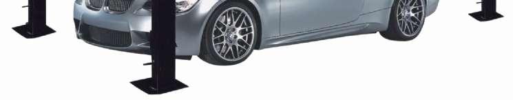
7 control handles and/or buttons dry, clean and free from grease and oil. STAY ALERT. Watch what you are doing. Use common sense. Be aware. CHECK FOR DAMAGED PARTS. Check the working condition of moving parts, breakage of parts or any condition that may affect its operation. Do not use lift if any component is broken or damage NEVER remove safety related components from the lift. Do not use lift if safety related components are damaged or missing. ALWAYS wear safety glasses. Every day eyeglasses should have impact resistant lenses. They are not safety glasses. READ AND UNDERSTAND ALL SAFETY WARNINGS & PROCEDURES BEFORE OPERATING LIFT. POST THESE SAFETY TIPS WHERE THEY WILL BE A CONSTANT REMINDER TO YOUR LIFT OPERATOR. FOR SPECIFIC INFORMATION OF THE LIFT, ALWAYS REFER TO THE LIFT MANUFACTURER S MANUAL. Improper installation can cause accelerated wear, resulting in catastrophic failure such as property damage and body injury. Manufacturer will assume no liability for loss or damage of any kind, caused by not following the operation manual. Read this installation manual thoroughly before attempting to install or operate the lift. 2. Introduction on Main Parts of the Lift The four post parking lift is the more convenient lift for parking the vehicle. The following words will help you understand the working principle of the device before using. Please read this instruction manual carefully, so it will help you operate and use maintain this device in correct way and prolong its lifespan. The lift is characterized with its simple and reasonable structure, low noise, and steady rising and lowing. After installation, connect the power to the power unit, the gear begin to work and the hydraulic oil enter the oil cylinder and push the piton rod up, which cause the chain lift the two platforms to rise. Since the minimum lifting height of the equipment is quite low, this device can be used widely. Because it s convenient to operate, it s used as the necessary maintenance equipment. It s not allowed to lift vehicle whose rated weight is above 4000kg with this equipment. 3. Main parameters of the equipment 3.1 Outside Dimension Picture 7
8 3.2 Lift parameter chart Total Height 2122mm/2322mm Lifting/Dropping Time 50s The Maximum Lifting Height 1850mm/2000mm Overall length: 4457mm/4831mm Rated Load 4000kg/4000kg Motor Power 2.2kw Working Voltage 3~400V+N+PE 1~230V+N+PE Noise Level 70dB(A) Oil Pressure 20MPa 8
9 4 Installation of the equipment 4.1 Installation parts included 3 drip trays 1 jack tray SELECTING SITE: Before installing your new lift, check the following points. OVERHEAD OBSTRUCTIONS: The area where the lift will be located should be free of overhead obstructions such as heaters, building supports, electrical wires etc. FLOOR REQUIREMENTS: Visually inspect the site where the lift is to be installed and check if there is cracked or defective concrete. This lift must be installed on a solid level concrete floor with no more than 2 degrees of slope. A level floor is suggested for proper installation and level lifting. If a floor is of questionable slope, consider a survey of the site and the possibility of pouring a new level concrete slab. This lift is designed to be installed on a minimum of 180mm thick, 3500psi, steel reinforced concrete. Do not install this lift on asphalt, wood, or any other surface other than described. DO NOT install this lift outdoors unless special consideration has been made to protect the power unit from weather conditions. The Power unit is not water proof!!! DO NOT begin installation with lift close to wall. It is necessary to leave adequate clearance for installing safety linkage rods. Allow 1524mm for clearance. NOTE The power unit can be placed in two locations, front left or rear right Unpacking: Unpack the lift close to the installation site. Review your packing list and assembly drawing to verify that you have all the parts. Layout a chalk line on the floor following the floor plan (See pic) Stand the column in place making sure the power unit mounting bracket at the correct location and the lock blocks facing outward. TOOLS recommended "Rotary Hammer Drill or Similar (If Anchoring / Not required) "Medium Crescent Wrench "φ19" Masonry Bit (If Anchoring / Not required) "Medium Pipe Wrench 9
10 "Hammer "Crow Bar" 4 Foot Level "Chalk Line "Open-End Wrench Set: "Medium Flat Screwdriver "Socket and Ratchet Set: "Tape Measure: 5m Minimum "Hex-Key / Allen Wrench Set "Needle Nose Pliers COLUMN & CROSSRAIL INSTALLATION Lay down rear columns. Position the Cross rail at the top of the two columns. (Both cross rails are the same ) Install the Cross rail in the column by sliding the plastic guide blocks into the column channel. The safety latch must be positioned in the same level from the ground, and make safety latch facing towards the outside of the lift when you stand the columns back up. Manually open the safety latch devise on each side of the cross rail and slide the cross rail down until it rests on the safety lock position closest to the floor. Repeat the procedure for the left columns and cross rail. Stand the assembled columns up in positions indicated on the floor plate. Track Installation Start the track with the cylinder. This track will be located with the hose Connection facing out toward the column with power unit bracket attached. With an assistant, pick up and place one end of the main side track on the cross rail, and then pick up and place the other end on the opposite cross rail (if you have three assistants, place both ends at the same time). Use a large screwdriver or aligning punch to align the mounting holes in the cross rails with the mounting holes in the track. Do not leave the tracks unbolted install the mounting bolts immediately! Install M12X100 mounting bolts and M12 washers thru the ramp brackets and wheel stops. Make sure the bolt head is on the flat side of the bracket. Install the two ramp brackets and two wheel stop with bolts and washers as you secure the main side track to the cross rail. Secure the bolts with M12 washers and nuts placed hand tight. Now, install the offside track and again secure with ramp brackets, wheel stops with M12X100 bolts and nuts. After both tracks are installed, tighten all bolts M12X100 bolts -torque -60 N-M. Find the top hat (4 each), M*12*25(4 each), M12 nuts (4 each) and M12 flat washers (4 each), M16 nuts (4 each) and M16 flat washers (4 each) holes for cable face towards the center of the lift. Secure the leg caps with M16X35 bolts. Place the bolts with washers in through channel and secure with washers and nuts on the outside of the leg. Insert the bolt end of the cable through the opening in the offside track, then run cable ¼ turn or 90 degrees around the pulley on the cross rail. Secure the bolt end to the leg top cap. Place washer and nut on threaded end hand tight. Safety Latch Linkage Installation: Locate and identify the components needed to install the safety latch linkage rods. Install the spacers from on the straight threaded end of the M12X1250 bent rod and the threaded end of the M12X2015 (for standard type) /2385(for extra long type) straight safety latch linkage rod. Install the M12X1250 bent safety latch linkage rod into the main side track adjacent to back end of the cylinder (opposite the cylinder rod). Safety latch linkage rod should pass through guide tubes on underside of track. Install the M12X2015 (for standard type) /2385(for extra long type) straight safety latch linkage rod into the main side track from the opposite end. The rod should pass through two guides on the underside of the main side track. 10
11 Install the 90 fitting w/o-ring in the base of power unit pump next to the lever operated release valve. IT IS NOT NECESSARY TO USE TEFLON TAPE ON O-RING FITTING Connect the 2200MM hose to the fitting on the power unit. Attach the other end of the 2200MM hose to outside fitting in main side track. Place a funnel into vent cap hole and fill the tank with one of the following fluids: AW-32 or ISO-32 hydraulic oil. Mobile DTE 24, or Texaco HD 32 DO NOT USE DEXRON IN THIS LIFT! This tank will hold approximately 10L Relocating or changing components may cause problems. Each component in the system must be compatible; an undersized or restricted line will cause a drop in pressure. All valve, pump, and hose connections should be sealed and/or capped until just before use. All parts should be supplied from manufacture. Air hoses can be used to clean fittings and other components. However, the air supply must be filtered and dry to prevent contamination. Most important -cleanliness -contamination is the most frequent cause of malfunction or failure of hydraulic equipment. Check Pulley Cover and Lock Collars: Before proceeding, double check to make sure the locking shaft collars for the cross rail cable pulleys are tight and secure. Check the pulley cover (2-RIGHT and 2 LEFT) over the shaft located on the pulley side of each cross rail. CHECK to make sure the pulley and cover are firm against the locking shaft collar already in place. Check the additional lock collar on the outside of the shaft is tight and secure. To prevent personal injury or death, cross rail lock collars must be tight. If they are ever removed -always make sure the locking shaft collars are tight and secure. Check the cross rail locking assembly before use. Make sure all bolts and collars are tight. The assembly is pre-installed from the factory but parts may come loose during shipping. After installation is completed, before start up, be sure to inspect and tighten all bolts. 4.2 Operation To raise the lift Position the vehicle at the centre of the platform. Check to make sure that the vehicle is secured. Press GREEN button to raise the vehicle To rest the lift in standing position at the desired height by releasing GREEN button. Always ensure that the lift rests on the safety before any attempt is made to work on or near the vehicle. To lower the lift Be sure the safety area is free of people and objects; Raise the lift a little bit by pushing GREEN button to clear off the safety; Press the release handle and at the same time also press unloading handle on the power unit to lower the lift. Lower the lift completely 11
12 5. Checking Points before Using 5.1 General Checking Points Item Detail Method How to avoid 1 Lifting has abnormal sound visual Lubricating, listen replacement 2 the overall appearance of the lift get damage and skew 3 Wire wheels get deformation and damage 4 lifting hydraulic system has abnormal sound and oil spills visual visual visual listen Maintenance, replacement cleaning 5 Has trash inside the column visual Remove, maintenance and replacement 6 Pull four insurance manipulation handles 7 Check the chain, the steel cable is normal no damage visual Visual Take off guard, adjust steel cable and replace new one New replacement 8 Check if the connection is loose bolts parts 9 Check the sprocket, the steel cable wheel whether they are normal no rupture and so on 10 Check the chain, the steel cable wheel if their rotation are normal Visual Operation and visual Operation and visual Re-strengthening and fixed New replacement Oiling Lubricating cleaning new replacement 11 Check up and down movement of two landslide is normal, comfortable and non-jitter 12 Check the action of the four insurance block if it s normal and comfortable (with automatic insert action), check the insurance steel cable if it s loose injury 13 Whether it is automatically stopped when no-load up to the highest location Operation Foreign body cleaning oiling cleaning Operation visual listen Foreign body cleaning oiling cleaning adjustment or new replacement Operation Repair new replacement 14 Check power unit is working properly without abnormal noise 15 Inspect tanks, oil hoses and connecting joints is normal no leakage 12 Operation listen Operation visual Repair new replacement Repair new replacement
13 6. Packing, transport and storage Only skilled personnel who are familiar with the lift and this manual shall be allowed to carry out packing, lifting, handling, transport and unpacking operations. 90%of components were pre-assembled and packed with blister packing in steel frame for shipment. Power unit was packed together with the lift, and power unit stand was packed and fixed on above lifts. Lifting and handling. When loading/unloading or transporting the equipment to the site,be sure to use suitable loading (e.g. cranes,trucks) and hoisting means. Be sure also to hoist and transport the components securely so that they cannot drop, taking into consideration of the package s size, weight and centre of gravity and its fragile parts. Storage and stacking of packaged lifts. Packaged lifts must be stored in a covered place, out of direct sunlight and at a temperature between-10 C and +40 C. Delivery and check of packages. When the lift is delivered, check for possible damages due to transport and storage; verify whether the points are included which is specified in the manufacturer s confirmation of order. In case of damage in transit, the customer must immediately inform the carrier of the problem. Packages must be opened carefully, not to cause damage to people (keep a safe distance when opening straps) and parts of the lift (be careful the objects do not drop from the package when opening). 7. Trouble Shooting Malfunctions Cause Solution The power source or power equipment is malfunctioning. Generator does not work. Check up the power fuse, the contact in the junction box of motor, micro switch, and the condition of up button, change the damaged part. Generator roars and does not work. When the lift is rising,it creeps. Noise is too loud when the lift is working. The lift can t rise. a. The top of vane wheel is deformed. b. Capacitor is damaged. c. The voltage is too low. The equipment is used overload. Air has entered the hydraulic system, and the oil box lack oil. The sliding and rotational part lack lubrication and or change the pin roll. a. There is something wrong with the power unit. b. the button on the power unit is damaged. 13 a. straightening b. replace for new parts c. check up by electric technicians Rise repeatedly to remove the air, and add oil to oil box. Add lubrication, change the pin roll. a. Maintain or change for new parts. b. Maintain or change for new parts.
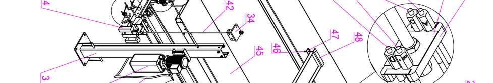
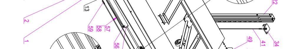
14 When lift is rising the speed is slow and heavy. The lift can t drop. c. Leakage of oil pipeline c. Clean, tighten and change for new parts. a. There is not enough hydraulic oil. a. Add hydraulic oil b. Leakage of oil pipeline b. Maintenance, tighten and c. Oil filter is stopped up. change for new parts. a. The security block is not open. b. Magnets are damaged heavily. c. Disassemble and clean. a. Rise first then drop, or maintain. b. Change for new parts. 8. Hydraulic diagram Item Name Item Name Item Name 1 cylinder 4 Gear pump 7 Release valve 2 Explosion-proo 5 Motor 8 Speed control valve f throttle valve 3 Overflow valve 6 One way valve 9 filter 10. exploded drawing 14


15 15
16 16
17 No. Parts Qty No. Parts Qty 1 L=2000mm hose 1 35 Cover assembly 4 2 Power unit 1 36 Stop plate 2 3 Main column 1 37 M12*90 bolt 4 4 Nylon block 8 38 Cylinder mount 1 5 Safety spring(two side each two) 4 39 Insurance plate 1 6 Safety lock 4 40 L=8060mm steel cable 1 7 Chuck ring 8 41 L=4020mm steel cable 1 8 M6*32 bolt 8 42 L=6620mm steel cable 1 9 D6 flat washer 8 43 L=2580mm steel cable 1 10 d6 spring washer 8 44 Sub runway assembly 1 11 M6 nut 8 45 Main runway assembly 1 12 Short rod 2 46 M6*10 screw 4 13 Linkage rod assembly 1 47 Nylon block 2 14 Space ring 2 48 Jack tray assembly 1 15 M8*12 bolt 8 49 Stop plate 2 16 Long rod screw 2 50 Stop bracket 2 17 Crossbeam assembly 2 51 Ramp assembly 2 18 screw 2 52 M12*100 bolt 4 19 B clip 4 53 Short linkage rod assembly 1 20 Caster kit axle 4 54 Middle lingkage rod assembly 1 21 Caster kit assembly 4 55 cylinder 1 22 Sub column 3 56 Throttle valve 1 23 Lock axle 4 57 L=1860mm hydraulic hose 1 24 M12*30 bolt fitting 1 25 D12 washer Connecting nut 2 26 D12 spring washer Chuck ring 2 27 M12 nut M10*90 screw 6 28 Space ring 2 62 Chuck ring 2 29 Pulley 6 63 M6*12 screw 4 30 bearing 6 64 Oiless bearing 4 31 D52 snap ring 6 65 pulley 4 32 Space ring 4 66 M8*20 screw 4 33 Cable pulley assembly 4 67 Safety lock axle 4 34 Top plate assembly 4 68 Cylinder axle 1 17
ATTENTION. 1. Do not attempt to use the power unit to extend your cylinder. This must be done manually.
 NSS8XLT Installation Manual ATTENTION By following the instructions in this manual you can save yourself much time, frustration and money. The installation of your lift will take 4-5 hours. Do not rush.
Models PR-12F PR-12C PR-15C SURFACE MOUNTED TWO-POST LIFTS INSTALLATION AND OPERATION MANUAL
 Forward this manual to all operators. Failure to operate this equipment as directed may cause injury. INSTALLATION AND OPERATION MANUAL SURFACE MOUNTED TWO-POST LIFTS Models PR-12F PR-12C PR-15C Keep this
GLO-8000 SERIES (GLO-8000 & GLO-8000XLT)
") GLO-8000 SERIES (GLO-8000 & GLO-8000XLT) 8,000 LBS. CAPACITY FOUR-POST STORAGE LIFT INSTALLATION & OPERATION MANUAL SERIAL NUMBER: INSTALLATION DATE: EAGLE EQUIPMENT 1-800-336-2776 REV2011 03.0 BD SHIPPING
GLO-8000 SERIES (GLO-8000 & GLO-8000XLT) 8,000 LBS. CAPACITY FOUR-POST STORAGE LIFT INSTALLATION & OPERATION MANUAL SERIAL NUMBER: INSTALLATION DATE: EAGLE EQUIPMENT 1-800-336-2776 REV2011 03.0 BD SHIPPING
GLO-7000 SERIES (GLO-7000 & GLO-7000XLT)
") GLO-7000 SERIES (GLO-7000 & GLO-7000XLT) 7,000 LBS. CAPACITY FOUR-POST STORAGE LIFT (BLUE) INSTALLATION & OPERATION MANUAL SERIAL NUMBER: INSTALLATION DATE: EAGLE EQUIPMENT 1-800-336-2776 (STANDARD) SHIPPING
GLO-7000 SERIES (GLO-7000 & GLO-7000XLT) 7,000 LBS. CAPACITY FOUR-POST STORAGE LIFT (BLUE) INSTALLATION & OPERATION MANUAL SERIAL NUMBER: INSTALLATION DATE: EAGLE EQUIPMENT 1-800-336-2776 (STANDARD) SHIPPING
Models: SURFACE MOUNTED FOUR-POST LIFTS INSTALLATION AND OPERATION MANUAL
 Forward this manual to all operators. Failure to operate this equipment as directed may cause injury. INSTALLATION AND OPERATION MANUAL SURFACE MOUNTED FOUR-POST LIFTS Models: FL-18 BP-18 BP-27/ BP-27A
Model FP14KO-A Wheel alignment & Open Front Four-Post Lift
 Model FP14KO-A Wheel alignment & Open Front Four-Post Lift ( 14000LBS / 6300Kg Capacity) ASSEMBLY & OPERATION INSTRUCTIONS ( Series T1) 2009.7. INTRODUCTION Model FP14KO-A is a four-post lift is used in
Index. 1. Important safety instructions Overview of the lift Installation instructions Operation instructions 8-9
 2 Index 1. Important safety instructions 4-5 1.1 Safety Warnings 1.2 Qualified personnel 1.3 Safety 1.4 Warning signs 2. Overview of the lift 6 2.1 General descriptions 2.2 Technical data 2.3 Construction
Read this entire manual before operation begins.
 Read this entire manual before operation begins. Record below the following information which is located on the serial number data plate. Serial No. Model No. Date of Installation Contents Specifications.............
Model SL-12K-A SCISSOR LIFT. wheel alignment model. (11000 LBS / 5000Kg Capacity) INSTALLATION & OPERATION INSTRUCTION (SECOND EDITION)
 INSTALLATION & OPERATION INSTRUCTION (SECOND EDITION)") Model SL-12K-A SCISSOR LIFT wheel alignment model (11000 LBS / 5000Kg Capacity) INSTALLATION & OPERATION INSTRUCTION (SECOND EDITION) 2007. 6. CONTENTS Chapter 1 Introduction & Specifications ---------------------------------------
Model SL-12K-A SCISSOR LIFT wheel alignment model (11000 LBS / 5000Kg Capacity) INSTALLATION & OPERATION INSTRUCTION (SECOND EDITION) 2007. 6. CONTENTS Chapter 1 Introduction & Specifications ---------------------------------------
Model PL-7 / PL-7X AUTOMOBILE STACKER INSTALLATION AND OPERATION MANUAL
 Forward this manual to all operators. Failure to operate this equipment as directed may cause injury. AUTOMOBILE STACKER INSTALLATION AND OPERATION MANUAL Model PL-7 / PL-7X Keep this operation manual
Model FP12K-K Flat Deck Four-Post Lift
 Model FP12K-K Flat Deck Four-Post Lift (12,000LBS Capacity) ASSEMBLY & OPERATION INSTRUCTION 2006.4. TABLE OF CONTENTS Important Note--------------------------------------------------------------------------------Page
ASSEMBLY & OPERATION INSTRUCTION MANUAL
 Sliding Bridge Jack 3,500 lbs. Capacity ASSEMBLY & OPERATION INSTRUCTION MANUAL TABLE OF CONTENTS Specifications... 2 Description & Features... 3 Installation Instructions... 4 Safety Instructions... 4
Read this entire manual before operation begins.
 Read this entire manual before operation begins. Record below the following information which is located on the serial number data plate. Serial No. Model No. Date of Installation Contents Specifications.............
Jema Autolifte A/S. Manual Release INSTALLTION, OPERATION AND MAINTENANCE MANUAL JA3500F ORIGINAL FOUR POST LIFT. Capacity: 3500KG
 Jema Autolifte A/S ORIGINAL JA3500F FOUR POST LIFT Capacity: 3500KG Manual Release INSTALLTION, OPERATION AND MAINTENANCE MANUAL Read this entire manual carefully and completely before installation and
CONTENTS. Product Features and Specifications...1. Installation Requirement Steps of Installation.. 5. Exploded View Test Run...
 CONTENTS Product Features and Specifications...1 Installation Requirement... 3 Steps of Installation.. 5 Exploded View...18 Test Run...21 Operation Instruction...22 Maintenance... 23 Trouble Shooting...
Read this entire manual before operation begins.
 Read this entire manual before operation begins. Record below the following information which is located on the serial number data plate. Serial No. Model No. Date of Installation Contents Specifications.............
CONTENTS. Product Features and Specifications...1. Installation Requirement Steps of Installation.. 5. Exploded View Test Run...
 CONTENTS Product Features and Specifications...1 Installation Requirement... 4 Steps of Installation.. 5 Exploded View...21 Test Run...26 Operation Instruction...27 Maintenance... 28 Trouble Shooting...
CONTENTS. Product Features and Specifications Installation Requirement Installation Exploded View Operation Instruction...
 1 CONTENTS Product Features and Specifications... 3 Installation Requirement... 5 Installation... 6 Exploded View... 20 Test... 22 Operation Instruction... 25 Maintenance... 26 Trouble Shooting... 27 Parts
TP15KC-KX Two-Post Clear Floor Lift
 TP15KC-KX Two-Post Clear Floor Lift (Symmetric) 15,000 lbs. Capacity (3,750 lbs. Max per Arm) ASSEMBLY & OPERATION INSTRUCTION MANUAL Feb. 2017 IMPORTANT NOTES READ THE INSTALLATION AND OPERATION MANUAL
Model FP14KA-C Alignment Four-Post Lift
 Model FP14KA-C Alignment Four-Post Lift (14000 LBS Capacity) ASSEMBLY & OPERATION INSTRUCTION 2006.4. TABLE OF CONTENTS Important Note--------------------------------------------------------------------------------Page
Instruction Manual For Auto Shift Hydraulic Lift Table
 Instruction Manual For Auto Shift Hydraulic Lift Table Model Number: CART-550-AS Note: Owner/Operator must read and understand this Instruction Manual before operating the lift & tilt table. Contents 1
CONTENTS. Product Features and Specifications Installation Requirement Steps of Installation 4. Exploded View Test Run...
 CONTENTS Product Features and Specifications... 1 Installation Requirement... 3 Steps of Installation 4 Exploded View... 14 Test Run... 16 Operation Instruction... 19 Maintenance... 20 Trouble Shooting...
CONTENTS. Product Features and Specifications...1. Installation Requirement...3. Steps of Installation...4. Exploded View Test Run...
 TP10AS 2-POST LIFT CONTENTS Product Features and Specifications...1 Installation Requirement...3 Steps of Installation...4 Exploded View...24 Test Run....28 Operation Instruction...29 Maintenance...30
Read this entire manual before operation begins.
 Read this entire manual before operation begins. Record below the following information which is located on the serial number data plate. Serial No. Model No. Date of Installation Contents Specifications.............
Perfect Park 7000 Installation & Unloading Instructions Operating Manual
 Perfect Park 7000 Installation & Unloading Instructions Operating Manual 1) Always file a claim with the truck line if the lift has been damaged! (If you don t originally notice the damage, but find some
Installation Instructions X-Force UTV Lift (000 Series) Capacity 2,275 lbs (1,035 kg)
 Capacity 2,275 lbs (1,035 kg)") Installation Instructions X-Force UTV Lift (000 Series) Capacity 2,275 lbs (1,035 kg) Read entire manual before assembling, installing, operating, or servicing this equipment. LP20640 IN20793 September
Installation Instructions X-Force UTV Lift (000 Series) Capacity 2,275 lbs (1,035 kg) Read entire manual before assembling, installing, operating, or servicing this equipment. LP20640 IN20793 September
Read this entire manual before operation begins.
 Read this entire manual before operation begins. Record below the following information which is located on the serial number data plate. Serial No. Model No. Date of Installation Contents Specifications.............
Read this entire manual before operation begins.
 Rev. 12/12/2017 Read this entire manual before operation begins. Record below the following information which is located on the serial number data plate. Serial No. Model No. Date of Installation Contents
Atlas PV-9WP Addendum
 Atlas PV-9WP Addendum 9,000 lb. Capacity Two-Post Overhead Lift The Atlas PV-9WP above ground hoist is 6 inches wider than the Atlas PV-9P, giving it an overall width of 141 (11 9 ) and a drive thru width
FOUR POST LIFT STRONGMAN TOOLS. Manual to be used with only Strongman Tools Ltd 4 Post Lift
 FOUR POST LIFT STRONGMAN TOOLS Manual to be used with only Strongman Tools Ltd 4 Post Lift 2. SAFETY WARNINGS Thoroughly read this manual before operating the lift and comply with the instructions. Always
Floor Plate Style Lift And Overhead Beam Style Lift. Two Post Lift
 Floor Plate Style Lift And Overhead Beam Style Lift 9,000 POUND Two Post Lift ASSEMBLY & OPERATION INSTRUCTION TABLE OF CONTENTS Important Note Page 3 Definition Page 4 Preparation and General Information
FP8K-B, FP8K-DX & FP8K-DX-XLT Four Post Storage Lifts
 FP8K-B, FP8K-DX & FP8K-DX-XLT Four Post Storage Lifts 8,000 lbs. Capacity (4,000 lbs. per axle) INSTALLATION / OWNERS MANUAL READ THIS MANUAL THOROUGHLY BEFORE INSTALLING, OPERATING, OR MAINTAINING THIS
It is the shop owner's responsibility to train all operators in lift operation and safety.
 2 Your new lift will provide years of dependable service if installed, operated and maintained properly. Read and be prepared to follow all safety, installation, operation, and maintenance instructions
Important. Contents. Contact us:
 Operator's Manual Third Edition Third Printing Important Read, understand and obey these safety rules and operating instructions before operating this machine. Only trained and authorized personnel shall
Read this entire manual before operation begins.
 Read this entire manual before operation begins. Record below the following information which is located on the serial number data plate. Serial No. Model No. Date of Installation Contents Important Information........
INSTALLATION MANUAL & OPERATION INSTRUCTIONS. OVERHEAD CAR LIFT 2-POST LIFT AUTO HOIST APlusLift HW-10KOH
 INSTALLATION MANUAL & OPERATION INSTRUCTIONS OVERHEAD CAR LIFT 2-POST LIFT AUTO HOIST APlusLift HW-10KOH 1 READ THIS MANUAL COMPLETELY BEFORE INSTALLING LIFT!!! DISTRIBUTED BY: Songa Enterprises LLC 8512
Lifting height 5.5" - 72" with adapters " Height overall 165" Width between columns 122" Drive through 109" Width overall 151.
 Model Number TP12KC-D Capacity 12,000 lbs. Lifting height 5.5" - 72" with adapters 79.625" Height overall 165" Width between columns 122" Drive through 109" Width overall 151.125" Arm extension 37.5" -
Package Contents Part A (3) I-Beam (1) Base (2) Other parts
 I-Beam (1) Base (2) Other parts") Page 1 Installation Instructions for 81245 Adjustable Height Gantry Crane 1-Ton Capacity Table of Contents Important Safety Information pg. 2 Specific Operation Warnings pg. 2 Main Parts of Product pg.
Page 1 Installation Instructions for 81245 Adjustable Height Gantry Crane 1-Ton Capacity Table of Contents Important Safety Information pg. 2 Specific Operation Warnings pg. 2 Main Parts of Product pg.
EZ LINER EXPRESS USERS MANUAL
 EZ LINER EXPRESS 2013 Vehicle Service Group CHIEF'S LIMITED ONE-YEAR WARRANTY & LIABILITY Chief Automotive Technologies warrants for one year from date of installation and/or purchase any components of
Important. Contents. Contact us:
 Operator's Manual First Edition Ninth Printing Important Read, understand and obey these safety rules and operating instructions before operating this machine. Only trained and authorized personnel shall
On-A-Roll Lifter Instruction Manual for Standard Models Read Before Use!
 On-A-Roll Lifter Instruction Manual for Standard Models Read Before Use! Important instructional, safety and precautionary information! It is the user s responsibility to exercise good judgment, common
Installation, operation and maintenance manual
 Installation, operation and maintenance manual HCT1LX30 FULL RISE SCISSOR LIFT READ THIS ENTIRE MANUAL BEFORE INSTALLATION TO ENSURE CORRECT OPERATION AND A LONG SERVICE LIFE 2 Tiraines str. Riga, LV 1058
30-SS1203A 12,000 LB CAPACITY SCISSOR ALIGNMENT LIFT INSTALLATION AND SERVICE MANUAL P/N:
 WITH STRENGTH 30-SS1203A 12,000 LB CAPACITY SCISSOR ALIGNMENT LIFT INSTALLATION AND SERVICE MANUAL P/N: 420-02553 CONTENTS Product Features and Specifications...1 Installation Requirement...3 Steps of
before serial number 2214
 before serial number 2214 Contents Page Safety Rules... 3 Pre-operational & Safety Inspection... 4 Operating Instructions... 6 Transport... 12 Maintenance & Routine Service... 12 Specifications... 14 SAFETY
ASSEMBLY & OPERATION INSTRUCTION MANUAL
 LR-26-PAD 6000 lb Capacity Low-Rise Pad Lift ASSEMBLY & OPERATION INSTRUCTION MANUAL 6,000 LB. LOW-RISE PAD LIFT Easy frame lifting on padded runways. Great for wheel and brake work, tire and wheel changing
HYDRAULIC PALLET TRUCK MODEL NO: PT540M/BM/CM & PT685BM/CM PART NO: , , , ,
 HYDRAULIC PALLET TRUCK MODEL NO: PT540M/BM/CM & PT685BM/CM PART NO: 7631700, 7631705, 7631710, 7631715, 7631720 OPERATION & MAINTENANCE INSTRUCTIONS LS0316 INTRODUCTION Thank you for purchasing this CLARKE
FP8K-B, FP8K-DX & FP8K-DX-XLT Four Post Storage Lifts
 FP8K-B, FP8K-DX & FP8K-DX-XLT Four Post Storage Lifts 8,000 lbs. Capacity (4,000 lbs. per axle) INSTALLATION / OWNERS MANUAL READ THIS MANUAL THOROUGHLY BEFORE INSTALLING, OPERATING, OR MAINTAINING THIS
ATD-4P9DXL. Four Post Lift. 9,000 lbs. Capacity. (4,500 lbs. per axle) INSTALLATION / OWNERS MANUAL
 INSTALLATION / OWNERS MANUAL") ATD-4P9DXL Four Post Lift 9,000 lbs. Capacity (4,500 lbs. per axle) INSTALLATION / OWNERS MANUAL Jan 2017 READ THIS MANUAL THOROUGHLY BEFORE INSTALLING, OPERATING, OR MAINTAINING THIS LIFT. WHEN DONE WITH
ATD-4P9DXL Four Post Lift 9,000 lbs. Capacity (4,500 lbs. per axle) INSTALLATION / OWNERS MANUAL Jan 2017 READ THIS MANUAL THOROUGHLY BEFORE INSTALLING, OPERATING, OR MAINTAINING THIS LIFT. WHEN DONE WITH
ATD-4P14CCA 14,000 lb Capacity Closed Front Alignment Lift ASSEMBLY & OPERATION INSTRUCTION MANUAL
 ATD-4P14CCA 14,000 lb Capacity Closed Front Alignment Lift ASSEMBLY & OPERATION INSTRUCTION MANUAL 14,000 LB. FOUR POST CABLE DRIVEN ALIGNMENT LIFT ATD-4P14CCA 14,000 lb. capacity Four post Cable driven
ATD2P11BS. Two-Post Clear Floor Bi-Symmetric Automotive Lift. Installation & Operation Manual. 11,000 lbs. Capacity. (2,750 lbs.
 Two-Post Clear Floor Bi-Symmetric Automotive Lift 11,000 lbs. Capacity (2,750 lbs. Max per Arm) Installation & Operation Manual 1. Safety Information 1.1 Note, Caution and Warning 1.2 Important Information
HEAVY DUTY TROLLEY JACK. Operation Manual
 HEAVY DUTY TROLLEY JACK 4T Operation Manual Make sure to read and fully understand the instruction manual before using this product and keep the manual properly 1 General Description Product Description
Instruction Manual. Low Profile Lift Table
 Instruction Manual Low Profile Lift Table Note: Owner/Operator must read and understand this instruction manual before using the low profile lift table. THANK YOU VERY MUCH FOR SELECTING OUR PRODUCT. THIS
Read this entire manual before operation begins.
 Revised 9/5/2018 Read this entire manual before operation begins. Record below the following information which is located on the serial number data plate. Serial No. Model No. Date of Installation Contents
INSTALLATION AND OPERATION MANUAL 1,500 POUND CAPACITY MOTORCYCLE / ATV LIFT Model: RML-1500XL
 PLEASE READ THE ENTIRE CONTENTS OF THIS MANUAL PRIOR TO INSTALLATION AND OPERATION. BY PROCEEDING YOU AGREE THAT YOU FULLY UNDERSTAND AND COMPREHEND THE FULL CONTENTS OF THIS MANUAL. FORWARD THIS MANUAL
OPERATION SERVICE PARTS TUGIT2. Manually Operated Short Handle Lever Hoist A3140-XXX
 OPERATION SERVICE PARTS TUGIT2 Manually Operated Short Handle Lever Hoist A3140-XXX Sold & Serviced by Morgan Aero 1450 80 th Street SW Everett WA U.S.A. 425/438.9600 SAFETY PRECAUTIONS WARNING! Improper
9,000 POUND TWO-COLUMN AUTOMOTIVE LIFT Model: NW-2-9KFP MANUAL
 9,000 POUND TWO-COLUMN AUTOMOTIVE LIFT Model: NW-2-9KFP MANUAL 1 9,000 POUND CAPACITY MODEL: NW-2-9KFP TWO-COLUMN AUTOMOTIVE LIFT READ THIS ENTIRE MANUAL BEFORE OPERATION BEGINS RECORD BELOW THE FOLLOWING
IMPORTANT INFORMATION
 TABLE OF CONTENTS IMPORTANT INFORMATION... 2 LIFT AREA LAYOUT INFORMATION... 3 TOOLS and EQUIPMENT REQUIRED FOR INSTALL... 4 INSTALLATION PROCEDURE... 5 FOUNDATION and ANCHORING REQUIREMENTS... 6 DEFINITION
Operators manual Bumpa 8 metre 110v Bumpa 10 metre 110v
 Operators manual Bumpa 8 metre 110v Bumpa 10 metre 110v SAFETY RULES Mk3 Bumpa Conveyor Danger Failure to obey the instructions and safety rules in this manual will result in death or serious injury. Do
Installation and Service Manual
 RESIDENTIAL PLATFORM LIFTS RPL400 / RPL600 Installation and Service Manual WARNING! STRICT ADHERENCE TO THESE INSTALLATION INSTRUCTIONS IS REQUIRED to promote the safety of those installing this product,
SCISSOR LIFT Model MR6K-38 /161108A 6,000lb Capacity Operation Manual
 SCISSOR LIFT Model MR6K-38 /161108A 6,000lb Capacity Operation Manual (Version A) 2009. Apr. CONTENT 1. Safety Note, Caution and Warning Important Information Safety Instructions 2. Technical Manual Product
Remove the 3-11mm nuts holding mirror on. Don t drop the nuts!
 2005-2012 Ford Mustang Puddle Lamp Kit Parts List: Quantity: Tool List: LED Lamps 2 Flat head screwdriver Seals 2 Ratchet & Socket set OR Nuts 2 Adjustable Wrench Wiring harness 1 Drill & 11/16 th bit
Color Logo use on white background only. Red: Blue: PMS Black Logo use on white background only
 Color Logo use on white background only Red: 0-0-0-0 Blue: PMS 29 0-6-0-0 Owners Manual LH400 (Lift Hoist 400) Platform Hoist This Hoist is Equipped with a Quick Change Cable Drum Effective: /18/2011 Black
Hand Pallet Truck NC. Operation Manual
 Hand Pallet Truck -------NC Operation Manual Operation Manual 1 Application Range This product is suitable for using in rated load of up to 5500lbs. This PL5500HD is the perfect jack for handling palletized
ATD-2P9A 9,000 lbs. Two Post Clear Floor Lift Owner s Manual
 ATD-2P9A 9,000 lbs. Two Post Clear Floor Lift Owner s Manual Features: Specifications: IMPORTANT NOTES READ THE INSTALLATION AND OPERATION MANUAL IN ITS ENTIRETY BEFORE ATTEMPTING TO INSTALL THE LIFT.
Installation/Operation/Service Manual
 TLX12/TLX12A Installation/Operation/Service Manual CONTENTS Product Features and Specifications...1 Installation Requirement...3 Steps of Installation...4 Exploded View...23 Test Run...28 Operation Instruction...29
AL625 & AL625HD INSTALLATION & OWNER S MANUAL
 AL625 & AL625HD INSTALLATION & OWNER S MANUAL These instructions are provided to assist you in the installation of the AL625. If you require further assistance, our trained staff is ready to provide you
Parallel Lift Rack MODEL RM
 Form 4401T, 09-03 Supersedes Form 4401T, 10-00 OPERATION INSTRUCTIONS Parallel Lift Rack MODEL RM Copyright 1998-2003 Hunter Engineering Company Contents 1. For Your Safety... 1 1.1 Warning/Instruction
Operators manual Hoddi 6 metre 110v Bumpa 8 metre 110v Bumpa 10 metre 110v
 Operators manual Hoddi 6 metre 110v Bumpa 8 metre 110v Bumpa 10 metre 110v SAFETY RULES Mk3 Bumpa Conveyor Danger Failure to obey the instructions and safety rules in this manual will result in death or
OPERATING & INSTRUCTION MANUAL
 251 Welsh Pool Rd Exton, PA 19341 610-941- 4333 www.safetyhoistcompany.com OPERATING & INSTRUCTION MANUAL VH-300 BRIGGS & STRATTON VH-300 HONDA IMPORTANT RETAIN THIS MANUAL For instruction on assembly
SERVICE GUIDE For WARN PULLZALL 120Vac P/N &
 SERVICE GUIDE For WARN PULLZALL 120Vac P/N 885000 & 885001 REPAIR / REPLACEMENT INSTRUCTIONS TROUBLE SHOOTING GUIDE 987604A2.doc Page 1 of 48 WARNING This guide identifies potential hazards and has important
TWO POST LIFT INSTALLATION AND OWNERS MANUAL
 TWO POST LIFT INSTALLATION AND OWNERS MANUAL DP15, DP15-2 Capacity 15,000 lbs. 1. TABLE OF CONTENTS 2. Important Information.. 2 3. Section 1 Owner s Manual Safety Instructions... 3 Monthly Maintenance...
WHIP INDUSTRIES, INC.
 WHIP INDUSTRIES, INC. WFP30R, WFP30R-E & WFP30R-EE STD., EXT. & E-EXT. 30,000 LBS CAPACITY FOUR POST ABOVE GROUND LIFT INSTALLATION INSTRUCTIONS & MANUAL WHIP INDUSTRIES, INC 3010 S MAIN ST. FORT WORTH,
Lincoln Hoist. Web Hoist Operating Manual. Lincoln Hoist
 Lincoln Hoist Web Hoist Operating Manual Lincoln Hoist Mfg. by Lincoln Precision Machining Company 121 Creeper Hill Road, P.O. Box 458, North Grafton, MA 01536 USA Toll Free (888) 306-7222 Phone (774)
Operating Instructions & Parts Manual. Fuel Tank Adapter
 Operating Instructions & Parts Manual Fuel Tank Adapter Model Number 40080 Capacity 80 lb.! This is the safety alert symbol. It is used to alert you to potential personal injury hazards. Obey all safety
WARNING NOTICE CAUTION ASSEMBLY INSTRUCTIONS
 MODEL 284 EZ-GLIDE SYSTEM 10' HIGH CUBE VAN DRIVER SIDE ALUMINUM DROP DOWN LADDER RACK ATTENTION Read and understand all instructions and warnings before operating or using this product. WARNING This product
Hydraulic Transmission Jack, Telescopic
 Operating Instructions & Parts Manual Hydraulic Transmission Jack, Telescopic Model 4000 400 (Air Operated) Capacity 000 lbs. 000 lbs. Model 4000 Model 400 U.S. Patent No. 6,02,377! This is the safety
INSTALLATION & OPERATION MANUAL
 Two-Post Clear Floor Lift (Asymmetric) 9,000 lbs. Capacity (2,250 lbs. Max per Arm) INSTALLATION & OPERATION MANUAL IMPORTANT NOTES READ THE INSTALLATION AND OPERATION MANUAL IN ITS ENTIRETY BEFORE ATTEMPTING
INSTALLATION MANUAL PACK RAT DRAWER UNITS MODELS NOTICE DANGER WARNING CAUTION
 TRUCK STORAGE SOLUTIONS SECURING YOUR REPUTATION INSTALLATION MANUAL ALUMINUM STEEL & ALUMINUM & STEEL SIDE ALL WITH PURPOSE CHEST PACK RAT DRAWER UNITS MODELS ATTENTION: PLEASE READ AND UNDERSTAND ALL
Installation Instructions Z-Gate Shifter
 Installation Instructions Z-Gate Shifter Part Number 80681 1998, 2001 by B&M Racing and Performance Products The B&M Z-Gate shifter can be used in vehicles equipped with most popular three speed automatic
1250 LB. CAPACITY MECHANICAL WHEEL DOLLY
 1250 LB. CAPACITY MECHANICAL WHEEL DOLLY 67287 SET-UP AND OPERATING INSTRUCTIONS Visit our website at: http://www.harborfreight.com Read this material before using this product. Failure to do so can result
Worldlawn Power Equipment, Inc. Industrial Park 2415 Ashland Ave. Beatrice, NE Toll Free Number:
 Operator s Manual R WYZ48/52/60CS BAGGER Worldlawn Power Equipment, Inc. Industrial Park 2415 Ashland Ave. Beatrice, NE 68310 Toll Free Number: 1-800-267-4255 OPERATOR S MANUAL This catcher manual is for
<THESE INSTRUCTIONS MUST BE GIVEN TO THE END USER> B&W
 B&W Trailer Hitches 6 Hawaii Rd / PO Box 86 Humboldt, KS 66748 P:60.473664 F:60.869.903 Turnoverball Gooseneck Hitch Installation Instructions MODEL 08
PNEUMATIC SLIDING VALVE
 INSTALLATION, OPERATION, & #: MM-SV001 6-23-09 Rev. A Page 1 of 8 PNEUMATIC SLIDING VALVE PART NUMBERS (Including, but not inclusive) SV704MSTS, SV714MSTS, SV754MSTS, SV764MSTS, SV774MSTS, SV706MSTS, SV716MSTS,
Instruction Sheet. 1/2 HP Portable Electric Pumps SAFETY FIRST. L2062 Rev. F 02/ IMPORTANT RECEIVING INSTRUCTIONS 2.
 Instruction Sheet 1/2 HP Portable Electric Pumps L2062 Rev. F 02/12 Index: English:...................................... 1-7 Français:.................................... 8-14 Deutsch:...................................
INSTALLATION MANUAL ALUMINUM & STEEL SIDE BOX
 TRUCK STORAGE SOLUTIONS SECURING YOUR REPUTATION INSTALLATION MANUAL ALUMINUM & STEEL SIDE BOX STEEL & ALUMINUM SIDE BOX WITH PACK RAT DRAWER UNITS MODELS ATTENTION: PLEASE READ AND UNDERSTAND ALL INSTRUCTIONS
TW 250 B4.5 Clear Floor Two Post Lift Lifting Capacity 5000KG
 TW 250 B4.5 Clear Floor Two Post Lift Lifting Capacity 5000KG Installation, Operation and Parts Manual Please read this entire manual carefully and completely before installation or operation of the lift.
Installation Instructions Capacity 10,000 lbs. (100 Series Lift)
") Installation Instructions Capacity 10,000 lbs. (100 Series Lift) IMPORTANT Reference ANSI/ALI ALIS, Safety Requirements for Installation and Service of Automotive Lifts before installing lift. OPERATING
Installation Instructions Capacity 10,000 lbs. (100 Series Lift) IMPORTANT Reference ANSI/ALI ALIS, Safety Requirements for Installation and Service of Automotive Lifts before installing lift. OPERATING
Operator Manual. The most important component is you. This operator manual. has information for. all models of series. B plus some options and
 Operator Manual This operator manual has information for all models of series B plus some options and accessories. Some of the illustrations and information may not apply to your truck. The most important
2,000 Lbs Heavy-Duty Engine Stand
 ITEM#: TR29005 2,000 Lbs Heavy-Duty Engine Stand WARNING: Read carefully and understand all ASSEMBLY AND OPERATION INSTRUCTIONS before operating. Failure to follow the safety rules and other basic safety
HYDRAULIC BENCH PRESS 50,000kg
 OWNER S MANUAL PRODUCT CODE: 2037T HYDRAULIC BENCH PRESS 50,000kg Working Capacity Height Width Depth Weight 50,000kg 1660mm 1220mm 800mm 236kg Made in China to TQB Brands Pty Ltd specifications WARNING
LKS300/LKS450 OPERATOR S MANUAL
 LKS300/LKS450 OPERATOR S MANUAL SAFETY RULES SHIFTA 300/450 Conveyor DANGER Failure to obey the instructions and safety rules in this manual will result in death or serious injury. Do Not Operate Unless:
Log Splitter. Owner/Operator Manual. Models HCWP1-26
 Log Splitter Owner/Operator Manual Models HCWP1-26 SAFETY..........................2 SAFETY WARNING SYMBOL.........3 SAFETY RULES.................. 4-5 SPECIFICATIONS................. 6 CONTROLS AND FEATURES.......
OPERATOR S MANUAL. 20-bu 3-Point Hitch Material Collection System. LP65048 Supplier ST /07/2017 English. North American Edition Printed in USA
 OPERATOR S MANUAL 20-bu 3-Point Hitch Material Collection System LP65048 Supplier ST48289 11/07/2017 English North American Edition Printed in USA Introduction Using Your Operator s Manual Read this entire
MODEL SCA Installation and Operation Manual Important:
 MODEL SCA Installation and Operation Manual Important: This manual contains specific cautionary statements relative to worker safety. Read this manual thoroughly and follow as directed. It is impossible
CHEVY AVALANCHE 1/2-TON ONLY 3 BODY LIFT KIT INSTALLATION INSTRUCTIONS KIT# 10173
 3651 N Highway 89 Chino Valley, AZ 86323 (928) 636-7080 www.p-a-g.net CHEVY AVALANCHE 1/2-TON ONLY 3 BODY LIFT KIT INSTALLATION INSTRUCTIONS 2003-2005 KIT# 10173 Installation of a Performance Automotive
Model No. EE-6215E. Installation, Operation and Parts Manual. Distributed by. Clear Floor Two Post Lift, Electrical Release Lifting Capacity 5000KG
 Model No. Clear Floor Two Post Lift, Electrical Release Lifting Capacity 5000KG Installation, Operation and Parts Manual Distributed by Please read this entire manual carefully and completely before installation
Capacity (tonnes) 0.25t. No. of Falls 1. Load Chain (mm) Load Chain Grade 80
 0.25t. No. of Falls 1. Load Chain (mm) Load Chain Grade 80") Capacity (tonnes) Model NO. 0.25t K025 No. of Falls Load Chain (mm) 4 2 Load Chain Grade 80 Pull To Lift Rated Load (N) Test load (tonnes) Hand Chain (mm) Std. lift (ft) Net. Weight (lbs) Gross. Weight
Capacity (tonnes) Model NO. 0.25t K025 No. of Falls Load Chain (mm) 4 2 Load Chain Grade 80 Pull To Lift Rated Load (N) Test load (tonnes) Hand Chain (mm) Std. lift (ft) Net. Weight (lbs) Gross. Weight
AUTOMATIC FOODSERVICE EQUIPMENT. AUTOMATIC ELECTRIC BROILER MODELS 952E, 932E and 922E OWNER S MANUAL
 AUTOMATIC FOODSERVICE EQUIPMENT AUTOMATIC ELECTRIC BROILER MODELS 952E, 932E and 922E OWNER S MANUAL IMPORTANT: RETAIN THIS MANUAL IN A SAFE PLACE FOR FUTURE REFERENCE. FOR YOUR SAFETY: Do not store or
LIFTING MECHANISM PART NO SRM 965
 LIFTING MECHANISM B60Z [A230]; B80Z [A233]; C60Z [A478]; C80Z [A479]; W60Z [A231]; W65Z [A229]; W80Z [A234]; B60Z AC [B230]; B80Z AC [B233]; C60Z AC [B478]; C80Z AC [B479] PART NO. 1500202 4000 SRM 965
MODEL LR-2066 & LR-2866A HOIST INSTALLATION AND OPERATION MANUAL
 TRUCK BODIES & EQUIPMENT INTERNATIONAL, Inc. Website: www.rugbymfg.com E-mail: sales@rugbymfg.com Phone: 1-800-869-9162 03 5839 MODEL LR-2066 & LR-2866A HOIST INSTALLATION AND OPERATION MANUAL Hoist Serial