101B, 210X, ELM, 101X Frame Installation & Service Manual
|
|
|
- Sabina Newton
- 5 years ago
- Views:
Transcription


1 101B, 210X, ELM, 101X Frame Installation & Service Manual S001_B
2 Copyright 2011 by ALL rights reserved. Information in this document is subject to change without notice. Companies, names and data used in examples herein are fictitious unless otherwise noted. No part of this document may be reproduced or transmitted in any form or by any means, electronic or mechanical, for any purpose, without express permission of Anthony Manufacturing Co., Inc. Anthony products identified in this manual are designed and certified to meet or for safety, and for sanitation standards. European products meet requirements. Each customer is responsible for final site approval.
3 Table of Contents TABLE OF CONTENTS PRELIMINARY CONSIDERATIONS FOR DOOR AND FRAME SERVICING PROCEDURES Safety... 1 Tools... 1 Tips... 2 PARTS REPLACEMENT Diagram A: Model 101B & ELM Door Parts Placement... 3 Diagram B: Model 210X Door Parts Placement... 4 Diagram D: Model 101X Frame Parts Placement Diagram... 6 Diagram D: Parts Listing... 6 Diagram D-2: Model 101X Frame Parts Placement Parts Placement Detail Diagram... 7 Diagram D-2 Parts Listing... 7 Diagram D-3: Model 101X Frame Parts Placement Detail Diagram... 8 Diagram D-3: Parts Listing... 8 Diagram D-4: Model 101X Frame Parts Placement Detail Diagram... 9 Diagram D-4: Parts Listing... 9 Diagram E: Model 101X ELS Fluorescent Lamp Assemblies Diagram F: Door & Frame Assembly Diagram DOOR REMOVAL & REVERSAL Removing the Door Assembly From the 101X Frame Reversing the Door Swing DOOR MAINTENENCE & PARTS REPLACEMENT Removing and Replacing the Door Gasket Removing and Replacing the Door Rail Plastic Cover Replacing the Door Handle Cylinder Lock Repair and Replacement Removing and Replacing the Torque Rod Removing the Hold-Open Assembly Replacing the Hold-Open Assembly Hold-Open Assembly Standard and Reverse Geometry Door Heater Wire Replacement Removing and Replacing the Hinge Pin Glass Pack Replacement Procedures Ordering Replacement Doors REPLACMENT DOOR INSTALLATION Installing the Door Assembly Into the 101X Frame Torque and SAG Adjustment FRAME MAINTENANCE & PARTS PLACEMENT Torque Replacement Fluorescent Lamp Replacement Standard Lighting System Fluorescent Lamp Socket Replacement Power Receptacle Replacement Frame Heater Wire Replacement Ballast Replacement Frame Reassembly TROUBLESHOOTING /1/2011 i S001_B
4 Table of Contents Table 1: Door & Frame DOOR & FRAME ELECTRICAL SPECIFICATIONS Typical Heater Wire and Lighting Wiring Diagrams Typical Frame Wiring Diagram with Wire Lead Chart Frame Power-Typical Frame Multi-Ballast Configurations Table 2: Dew Point Chart Table 3: Lighting Amperage Chart Table 4: Table of AMP and BTU Charts Table 5: AMP & BTU Chart Reference Table 6: 101B Heater Amperages-Sheet Table 7: 10B Heater Amperages- Sheet Table 8: 101B Heater Amperages- Sheet Table 9: 101B Heater Amperages- Sheet Table 10: 101B Heater Amperages - Sheet Table 11: 210X Heater Amperages- Sheet Table 12: E2 Heater Amperages- Sheet Table 13: E2 Heater Amperages- Sheet Table 14: E2 Heater Amperages - Sheet Table 15: ELM Heater Amperages - Sheet Table 16: ELM Heater Amperages - Sheet Table 17: 101B Energy-Free BTU Chart Table 18: 101B Low Temperature BTU Chart Table 19: 101B Normal Temperature BTU Chart Table 20: 10B Normal Temperature ELS BTU Chart Table 21: 210X Low Temperature BTU Chart Table 22: 210X Normal Temperature BTU Chart Table 23: E2 Low Temperature BTU Chart Table 24: E2 Low Temperature ELS BTU Chart Table 25: E2 Normal Temperature BTU Chart Table 26: ELM Low Temperature BTU Chart Table 27: ELM Low Temperature BTU Chart Appendix A-1: ALTERNATE BALLAST MOUNTING Appendix A-2: ALTERNATE BALLAST MOUNTING Appendix A-3: ALTERNATE BALLAST MOUNTING Appendix B-1: DOC IN-0002 SUPPLEMENTAL HANDLE REPLACEMENT INSTRUCTIONS /1/2011 ii S001_B


5 PRELIMINARY CONSIDERATIONS FOR DOOR AND FRAME SERVICING PROCEDURES Safety Proper safety equipment includes: safety glasses work gloves work shoes NOTE: TURN OFF ALL ELECTRICAL POWER PRIOR TO BEGINNING WORK ON THE DOOR OR ON ANY ELECTRICAL. USE EXTRA CAUTION WHEN WORKING WITH OR AROUND THE DOOR GLASS PACKAGE. Tools Tools required for this procedure include: - #2 Phillips-head screwdriver - Flat-head screwdriver - Needle-nose pliers - Rubber or plastic mallet - 7 /16 and 1 /2 Hand Wrench - 5 /32 Hex Key - Wire stripper and cutter - Soldering iron - Heat Gun - Razor Knife NOTE: DO NOT USE POWER TOOLS FOR THE FOLLOWING PROCEDURES 2/1/ S001_B
6 Tips Complete replacement of wire assemblies is recommended whenever required. Splice wires only if necessary using proper materials such as, electrical tape, wire nuts, flux core solder and heat shrink. Apply liquid soap to rail plastic covers and gaskets upon installation to facilitate insertion into mounting grooves. Keep doors and frames clean for product efficiency. This can also help reduce energy consumption and potential health hazards. Whenever binding gasket or plastic parts, use food grade silicone. Whenever replacing fluorescent lamps, always replace lamp covers as well. Always use the correct tool for the job to be performed. This ensures proper installation and minimizes safety risks. If there is any doubt about the work to be performed, consult with a certified technician or Anthony representative. Preventative maintenance is recommended to ensure product longevity. 2/1/ S001_B
7 PARTS REPLACEMENT Diagram A: Model 101B & ELM Door Parts Placement No. Description 1. Torque Rod Assembly 2. Gasket with Magnet 3. Corner Pieces 4. Door Rail (Hinge side) 5. Door Rail (Handle side) 6. Top & Bottom Rail 7. Hold Open Backing Plate 8. Hold Open Fork & Spacer 9. Access Hole Cover 10. Top & Bottom Rail Cover 11. Side Rail Covers 12. Wedge Spacer 13. Vinyl Glazing 14. Glass Pack Assembly x 5 /8 Screws /16 x 3 /8 x 3 /8 Rivets x 5 /8 Screws 18. #42 Steel Rivets 19. Slimline Handle 20. Ground Wire Assembly 21. Hinge Pin 22. Sealant 23. Foam Mounting Tape 24. 3M Hot Melt Sealant 25. Door Handle Rail Insert 2/1/ S001_B
8 Diagram B: Model 210X Door Parts Placement No. Description 1. Torque Rod Assembly 2. Gasket with Magnet 3. Hold Open Fork 4. L.H. Corner Piece 5. R.H. Corner Piece 6. Handle Rail 7. Hinge Rail 8. Top Rail 9. Door Handle 10. Plate Backing 11. Access Hole Cover 12. Handle Mounting Block 13. Plastic Cover 14. Door Rail Filler 15. Cap 16. Door Glass Package /16 X 3 /8 Steel Rivet x 5 /8 Zink Screw x 5 /8 Black Screw x 3 /16 Screw 21. Weld Nut 22. Heater Wire Plug Ass y 23. Hinge Pin 24. Foam Tape 2/1/ S001_B
9 Diagram C: Frame Width Data Model 101X, 210X, elm 2/1/ S001_B
10 Diagram D: Model 101X Frame Parts Placement Diagram Diagram D: Parts Listing No. Description No. Description No. Description 1. Sill Frame 8. Flexible Aluminum Conduit 15. Hinge Pin Gib 2. End Frame 9. Heater & Lighting Wiring 16. Ground Jumper Assembly 3. Black Female Cap Plug 10. Screw-In Flexible Connector x 3 /16 Screw x SMS Screw 11. Flanged Frame Header 18. Center Mullion Contact Plate 5. Steel Lock Nut 12. Connection Diagram Label 19. End Frame Contact Plate 6. Warning & ID labels 13. Brand Labels 20. Ballast o Flex Connector 14. Warning Label 21. Bottom Contact Plate 2/1/ S001_B
11 Diagram D-2: Model 101X Frame Parts Placement Parts Placement Detail Diagram (Section A-A) Diagram D-2 Parts Listing No. Description No. Description No. Description 1. Frame 4. Lamp Socket 7. Lamp Mounting Clip 2. Fluorescent Lamp 5. Rocker Switch (ELS only) 8. Standard Lamp Cover 3. Center Mullion 6. ON / OFF Label (ELS only) 9. Black Cloth Mounting Tape 2/1/ S001_B
12 Diagram D-3: Model 101X Frame Parts Placement Detail Diagram (Section B-B) Diagram D-3: Parts Listing No. Description No. Description No. Description /4-20 Cinch Nut 18. Mullion Lens Retainer Clip 26. ELS Frame Shelf Post Bracket 11. Frame End Lockstrike Support 19. Lens Assembly (End Jamb) 27. Swing Doors Lockstrike Plate 12. Torquemaster 20. Center Mullion Lens 28. ELS Mullion Shelf Post Bracket 13. Lamp Socket 21. End Frame Lens Retainer Clip 29. STD Mullion Shelf Post Bracket 14. Perimeter End Cover x.219 Lampholder Screw x 3 /8 Taptite Screw 15. Socket Clip Mounting Screws 23. Heater Wire x 5 /16 Tap 1 Screw 16. Bottom Backup Plate 24. ELS Exterior Contact Plate 32. Torquemaster Plug Cap /16 x 11 /16 Foam Tape 25. Sill Cover 33. Zipper Strip 2/1/ S001_B
13 Diagram D-4: Model 101X Frame Parts Placement Detail Diagram (Section C-C) Diagram D-4: Parts Listing No. Description No. Description No. Description 34. Standard Lamp Socket 40. Mullion Shelf Bracket 46. Hold Open Stand-off 35. Receptacle Mounting Screw 41. Shelf Bracket Mounting Screw 47. Single Station Gib 36. Zipper Strip 42. Ballast 48. Dual Station Gib /4 x 7 /16 x.03 Flat Washer 43. Mullion Raceway Cover Plate 49. Single Hinge Pin Receptacle 38. Frame Raceway Cover Plate 44. Frame Extrusion 50. Dual Hinge Pin Receptacle /4-20 x.375 Black Screw x 1 Socket Mount Screw 2/1/ S001_B
14 Diagram E: Model 101X ELS Fluorescent Lamp Assemblies 2/1/ S001_B
15 Diagram F: Door & Frame Assembly Diagram 2/1/ S001_B


16 DOOR REMOVAL & REVERSAL Removing the Door Assembly From the 101X Frame 1. Using a flat-head screwdriver, loosen the tension on the door by turning the adjustment screw, located on the front of the torquemaster, to the right or clockwise. Refer to figure (A) 2. Test the door by opening it, and confirm that the torque tension does not retract the door from open position. 3. If tension remains, continue adjusting the torquemaster until all tension has been removed from the door. 4. Open the door to access the hold open device then loosen and remove hold-open bolt, using a phillips-head screwdriver. Refer to figure (B) A B 5. Remove the hold open stud using a 7/16 hand wrench. 6. Retract the door to a near-closed position. 7. Insert the top half of the needle-nose pliers into the grip-hole, located in the hinge pin spring-clip, and the bottom half of the pliers beneath the hinge pin shroud. Refer to figure (C) 8. Squeeze the pliers to clamp down on the hinge pin spring clip, allowing the clip to release the hinge pin from the receptacle gib of the frame, while simultaneously pulling the top of the door away from the frame. This will release and pull the hinge pin out of the hinge pin receptacle and gib. Refer to figure (D) ) C D 2/1/ S001_B

17 9. Continue pulling the top of the door assembly away from the frame until the top door rail clears the frame. 10. Lift and remove the door from the torquemaster and carefully set the door aside. Refer to figure (E) E Reversing the Door Swing 2/1/ S001_B
 of a turn.")
 A B 2.")


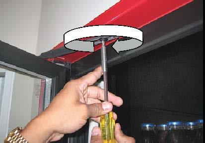
18 1. Using a flat-head screwdriver, loosen the torquemaster from its mount by turning the center mounting screw counter-clockwise less than one-half (1/2) of a turn. Refer to figure (A) Remove the Torquemaster, exposing the mounting hole in the bottom frame rail. Refer to figure (B) A B 2. Locate the mounting hole at the opposite side of the door opening. 3. Using the flat-head screwdriver, carefully pry underneath the plug cap and remove it. Refer to figure (C) \ C 4. Place the Torquemaster on the newly opened mounting hole, aligning the flanged corners of the mounting tabs Refer to figure (D) D 5. Insert the Torquemaster mounting tabs onto the mounting hole with the hollow end of the Torquemaster against the door frame. 2/1/ S001_B

 9.")


19 6. Confirm that the mounting flanges on the bottom of the torquemaster align with the corner mounting slots of the mounting hole in the frame. 7. Using a flat-head screwdriver, turn the Torquemaster mounting set-screw clockwise, for 1/2 a turn, to tighten the mount and lock it in place. Confirm that the torquemaster mounting is flush with the door frame. 8. Using a 7/16 open-ended hand wrench, loosen and remove the hold-open detent bolt from the top frame rail. Refer to figure (E) 9. Relocate and install the hold-open shoulder bolts into the opposite hold-open mount of the same door frame. Refer to figure (F) E F 10. If installing in Reverse Geometry, insert the hold-open stand-off into the frame header and install the detent bolt into the top of the door then tighten each with a 7/16 open-ended hand wrench (see page 22 for complete Reverse Geometry installation instructions). Refer to figure (G) 11. Open the access portal to the hinge pin wire connections in the rail on the hinge side of the door assembly. 12. Disconnect the Hot, Neutral and Ground wires of the hinge pin from the heater wire circuit and the ground terminal. Refer to figure (H) G H 13. Loosen and completely remove the hinge pin assembly from the top door rail. NOTE: Refer to Removing and Replacing the Hinge Pin on page 31 for complete replacement procedures. 2/1/ S001_B
20 14. Using a plastic mallet and a flat-head screwdriver, remove the torque rod from the bottom of the door assembly. Refer to figure (I) I NOTE: Refer to Removing and Replacing the Torque Rod on page 25 for complete Torque Rod replacement instructions. 15. Swap placement of the Hinge Pin and Torque Rod to the other s original mounting hole in the door assembly hinge side rail. 16. Reinstall the hinge pin and the torque rod completely into the ends of the door assembly hinge rail. 17. If necessary, lightly tap on the hinge pin and torque rod with a plastic or rubber mallet until each is fully seated into the top and bottom of the door. 18. Reconnect the hinge in wires and confirm that all connections are secure. 19. Check and confirm torque rod and hinge pin are correctly and completely installed. 20. Reinstall the door into the frame. NOTE: Refer to REPLACMENT DOOR INSTALLATION on page 38 for complete door installation instructions. 2/1/ S001_B
 and Refer to figure (B) A B 2. Carefully pull the gasket out of the grove in the plastic rail covers.")


21 DOOR MAINTENENCE & PARTS REPLACEMENT Removing and Replacing the Door Gasket 1. Begin removing the door gasket by lifting one corner of the gasket out of the groove. Refer to figure (A) and Refer to figure (B) A B 2. Carefully pull the gasket out of the grove in the plastic rail covers. Refer to figure (C) and Refer to figure (D) C D NOTE: The gasket is composed of soft materials with welded miter joints. Use extra care when manually extracting the gasket from the rail grooves to prevent damaging it as well as the plastic rail. 3. Align the two corners of the replacement gasket onto the top mitered corners of the plastic cover, with the gasket arrow facing the door rail and cover. 4. Press the gasket arrow into the grove in the center of the plastic cover corners until the edges of the gasket arrow catch and the arrow is initially inserted into the groove of the plastic cover. 5. Align the bottom two gasket corners with the bottom mitered corners of the plastic covers, aligning the gasket arrow with the grove in the plastic cover and press the corners into the grove until the arrow is fully inserted. 2/1/ S001_B
 E 7.")
. 8.")
22 6. Press the gasket firmly against the top plastic cover, sliding from side to side and applying full pressure against the gasket, forcing the gasket arrow into the of the groove in the plastic top cover. Refer to figure (E) E 7. Continue pressing the gasket arrow into the grooves of the remaining plastic covers, around the entire door rail perimeter (if necessary, a plastic or rubber mallet can be used to facilitate the arrow into the groove by applying a swift stroke onto the gasket- DO NOT damage the gasket or the glass). 8. Confirm that the entire gasket arrow has been completely inserted into the groove of all four plastic rail covers. Removing and Replacing the Door Rail Plastic Cover 1. Insert the end of a slot head screwdriver in between two plastic cover ends at the corner miter. Refer to figure (A) 2. Carefully twist the screwdriver to loosen the corner of the plastic cover lip from the door rail. 3. Continue to pry the plastic cover from the door rail until the entire end of the plastic rail is disengaged. Refer to figure (B) A B 2/1/ S001_B

23 4. Pull the plastic cover up and out of door rail grooves until the entire plastic cover is removed from the door rail. Refer to figure (C) 5. Repeat Step 2 through Step 4 to loosen and remove the three remaining plastic covers. 6. To install the new, replacement plastic covers, begin by aligning the replacement plastic cover evenly onto the door rail. 7. Insert the outer edge of the plastic cover into the outside groove of one of the door rails. Refer to figure (D) C D 8. Push the plastic cover down and inward, toward from the center of the door. 9. Slide along the entire length of the plastic cover while firmly applying pressure against it. Continue applying pressure down along the length of the entire door rail, inserting both the outside lip and the inside lip into the door rail grooves simultaneously. NOTE: Carefully tap the plastic cover using a plastic or rubber mallet with deliberate strokes, outward and away from the glass, may help seat the lips of the plastic cover into the grooves of the door rails. Refer to figure (E). E 10. Check the entire plastic cover and confirm that both the inside and outside lips are fully inserted into the door rail grooves. 11. Repeat this procedure, aligning each mitered corner, with the remaining plastic covers until all four plastic covers are properly installed onto door rails. 12. Confirm that each plastic cover is fully installed and the mitered corners properly aligned. 2/1/ S001_B

24 Replacing the Door Handle 1. Carefully remove the door gasket installed into the plastic cover over the door rail in which the door handle is installed (leaving the gasket on the remaining door rail assembly for easy reassembly is recommended). 2. Insert the end of a slot head screwdriver in between two plastic cover ends at the corner miter of the plastic cover over the door rail with the handle. 3. Twist the screwdriver to loosen the corner of the plastic cover lip from the door rail grooves. 4. Pry the plastic cover from the handle side of the door rail until the entire end of the plastic rail is disengaged and remove the entire plastic cover from the door rail with the handle. 5. Insert a 5/32 hex key or Allen Wrench into the door rail openings and into the screw head securing the door handle. 6. Turn the screw counter-clockwise to loosen and remove it. Refer to figure (A) A NOTE: In the event that the screw heads are obstructed, refer to product notification for instructions detailing the removal of the obstruction. Refer to Appendix B-1: DOC IN-0002 SUPPLEMENTAL HANDLE REPLACEMENT INSTRUCTIONS on page 93 instructions for more information. 7. Repeat Step 1 thru Step 6 with the second mounting screw and remove the handle assembly from the door. 2/1/ S001_B


25 8. Insert mounting screws into mounting holes until the ends of the screw protrude through the mounting holes. Refer to figure (B) 9. Insert the hex key or Allen Wrench into screw head. 10. Hold the Handle mounting holes against the protruding screw ends. NOTE: Make sure the handle is configured with the screws mated with the correct mounting holes in the handle. 11. Turn the first screw clockwise until the threads catch. 12. Repeat the last step to connect the remaining screw and handle mount. 13. Tighten each mounting screw. Refer to figure (C) ) B C 2/1/ S001_B
26 14. Confirm the handle is secure and flush-mounted to the surface of the door rail and reassemble the door.door Bumper Removal and Replacement 1. Using a phillips-head screwdriver, loosen and remove both self-threading screws and washers at each end of the bumper assembly; then remove bumper (leaving the gasket on the remaining door rail assembly for easy reassembly). 2. If necessary, remove bumper mounting brackets. Remove plastic covers from the longer, side door rails. Using a razor knife, carefully cut the silicone adhesive. Loosen and remove bracket mounting screws. Carefully remove mounting brackets. 3. Replace door bumper assembly mounting brackets. Completely clean each bracket of silicone adhesive residue. Apply a generous amount of fresh silicone adhesive to the outside of each mounting bracket. Insert new self-threading X 3/8 screws into the bracket mounting holes and into the door rail mounting holes. Using a phillips-head screwdriver, turn the screws clockwise until all four screws are tightened and both mounting brackets are securely fastened. Apply silicone adhesive along the seams of each bracket to ensure a proper seal. Allow for silicone adhesive to fully cure. 4. Replace the plastic covers to the door rails (refer to plastic cover replacement procedures). 5. Replace bumper assembly to the door. 2/1/ S001_B

27 6. Align the mounting holes in the bumper assembly with the holes in the mounting brackets. 7. Insert new self threading X 3/8 screws into the bumper assembly mounting holes. 8. Using a phillips-head screwdriver, turn the screws clockwise until each screw is tight and the bumper assembly is securely mounted. 9. Confirm that the bumper assembly is securely mounted to the door. Cylinder Lock Repair and Replacement 1. Remove gasket from door rail containing the lock (leaving the gasket on the remaining door rail assembly for easy reassembly). 2. Remove plastic cover from the door rail containing the lock assembly to expose access to the lock mount. Refer to figure (A) A 2/1/ S001_B

 B 4. Turn the lock screw counter-clockwise to loosen the screw. 5.")
 7. Remove the lock assembly, out from the lock housing and through the front of the door rail. 8.")

28 3. Insert a large phillips-head screwdriver into the lock access in the back of the door rail. NOTE: Once the lock screw has been removed, the screw washers and lock latch will come loose. Be certain that these components are secure prior to the removal of the lock screw, or they may become lost if dropped inside of the door rail. Refer to figure (B) B 4. Turn the lock screw counter-clockwise to loosen the screw. 5. Carefully remove the screw, lock washers and lock strike from the back of the lock assembly. Refer to figure (C) 6. If necessary, replace the strike. Refer to figure (D) 7. Remove the lock assembly, out from the lock housing and through the front of the door rail. 8. Replace lock assembly into housing inside rail. 9. Replace the strike washer, strike, lock washer and screw to the rear of the lock assembly and assemble in the correct order. Be certain that the strike is fully and correctly seated onto the end of the cylinder. 10. Turn lock screw clockwise to catch the threads and tighten the screw completely. DO NOT OVER-TIGHTEN. Refer to figure (E) C D E 11. Test lock and confirm that it works properly. 12. Replace the plastic cover and gasket (refer to plastic cover and gasket replacement instructions). 2/1/ S001_B


29 Removing and Replacing the Torque Rod 1. Carefully place a flathead screwdriver between the door rail and the washer beneath the torque rod. Refer to figure (A) A 2. Dislodge the torque rod from its mount by pushing on the torque rod or tap it loose using a plastic or rubber mallet. DO NOT use a steel-headed hammer. Refer to figure (B) B NOTE: Use caution when striking any tool with another tool. DO NOT use excess force when striking the screwdriver and potentially damaging the door. 3. Continue to carefully tap the torque rod, if necessary, until the torque rod and rod end disengage. 4. Carefully pull the torque rod assembly completely out the door rail. 2/1/ S001_B
 thru Refer to figure (E) Insert torque rod into the bottom of the door until it is fully seated.")


30 5. Reverse the process to re-install the torque rod assembly into the door rail. Refer to figure (C) thru Refer to figure (E) Insert torque rod into the bottom of the door until it is fully seated. If required, tap the torque rod assembly into the door rail using a plastic or rubber mallet, until the torque rod is fully seated into the door rail socket. C D E Removing the Hold-Open Assembly 1. Remove screws from the hold-open standoffs, which are located on the door rail and frame. Refer to figure (A) 2. Remove the hold open, standoffs and discard them. 3. When replacing the hold-open arm, reverse Step 1 by inserting the screw through the mounting hole in the arm and tightening it into the frame mounting hole using the #2 phillips head screwdriver. Refer to figure (B) A B * Picture for orientation & reference only. Actual Hold-open assembly may differ from item shown. Replacing the Hold-Open Assembly 1. Insert the pivot standoff into door. Add Loctite #271 to threads. Torque to 100 in/lb. 2. Place the pivot hole of the new hold open over the pivot standoff that is closest to the hinge pin. 3. Retain with a new truss head screw and torque to 16 in/lb (approximately #2 clutch setting on a professional screw gun). 4. Remove the vinyl cap from the detent bolt. 5. Insert the bolt up thru the hold open slot and then thru the detent spacer (flat side against frame). 6. Add loctite #271 to threads. Use a 7/16 hex wrench and torque into frame to 100 in/lb. 2/1/ S001_B
31 7. Add small amount of grease to detent surface. 8. Insure the truss head screw is seated on the end of the standoff and not the hold open. DETENT WASHER FRAME ASSEMBLY SCREW HOLD OPEN FORK PIVOT STANDOFF DETENT STANDOFF DOOR ASSEMBLY Hold-Open Assembly Standard and Reverse Geometry The 101B, 210X and the ELM models utilize reverse geometry for the Hold-Open assembly mounting configuration. Reverse geometry of the Hold-Open mount has the same assembly configuration as the standard geometry. The difference with reverse geometry is that the hold open fork and the mounting hardware are reversed. 2/1/ S001_B
32 STANDARD GEOMETRY: The Hold-Open fork slot, the Detent Standoff and the Detent Washer are mounted up, into the frame header rail. The fork pivot hole, along with the pivot standoff and pivot screw are mounted down into the top rail of the door frame REVERSE GEOMETRY: The fork pivot hole, along with the pivot standoff and pivot screw are mounted up, into the frame header rail. Conversely, the Hold-Open fork slot, the Detent Standoff and the Detent Washer are mounted down into the top rail of the door frame. The same installation specifications are applicable to reverse geometry mounting procedures. Refer to this section as well as the Hold-Open removal and replacement sections for basic installation procedures and mounting specifications of the Hold-Open assembly. DETENT WASHER FRAME ASSEMBLY SCREW HOLD OPEN FORK PIVOT STANDOFF DETENT STANDOFF DOOR ASSEMBLY 2/1/ S001_B
. 4.")
 A NOTE: Use caution, when using a metal or edged tool to remove the heater wire, to avoid damaging the wire or wire shielding.")
33 Door Heater Wire Replacement 1. Remove door assembly from the frame (refer to door removal instructions). 2. Remove door gasket (refer to door gasket removal section for gasket removal procedure). 3. Remove plastic cover from all door rails (refer to plastic cover removal section for the removal procedure). 4. Using a small, flat-head screwdriver, remove the access cover from the frame, to access the wiring (as with the plastic frame cover). Refer to figure (A) A NOTE: Use caution, when using a metal or edged tool to remove the heater wire, to avoid damaging the wire or wire shielding. NOTE: The wiring configuration differs per model and individual facility requirements. Make the necessary adjustments that may be required to complete this procedure. 5. Locate the mounting plate (if applicable) and two mounting screws for the cord and wire harness mounts, on the outside of the adjacent door rail. 6. Using a phillips-head screwdriver, loosen and remove each screw. 7. Carefully pull out and remove strain relief harness, as well as the loop terminal for the ground (green) wire. Refer to figure (B) B 8. Remove the wire terminals from the door rails. NOTE: Two terminals adjoin the ends of the heater wire with the hot and neutral wires from the power cord. Two different methods can be used to disconnect the heater wire from the power cord. 2/1/ S001_B
 12.")
 NOTE: If the replacement heater wire does not have terminated ends, then splice the wires together using wire nuts or solder and heat shrink.")


34 9. Open the wire terminals and remove the terminated wire ends. Refer to figure (C) C 10. Locate the heater wire in the grooves of all four door rails. The heater wire is usually shielded with a woven fiberglass sleeve. 11. Using a flathead screwdriver, pull the heater wire out from door rails. Refer to figure (D) 12. Manually pull out and remove the remaining heater wire. Refer to figure (E) 13. Install the terminated wire ends from the replacement heater wire, then close the wire terminals. Refer to figure (F) NOTE: If the replacement heater wire does not have terminated ends, then splice the wires together using wire nuts or solder and heat shrink. D E F Splicing wire ends with solder and shrink tubing 1. Cut the (black and white) power wires, after the terminals. 2. Strip a minimum of 1/2 of insulation from each wire, exposing the end of the each cut wire. 3. Strip a minimum of 1/2 of insulation from each end of the heater wire. 4. Insert one, two inch heat-shrink tube (not supplied) over each end of heater wire. 5. Slide each tube down, away from the wire ends. 6. Join the exposed end of each stripped wire, from the power cord, with each end of the stripped heater wire. 7. Twist the wire ends together and solder the adjoined wire ends using a soldering iron, flux and solder. 8. Slide each heat-shrink tube back up the heater wire and over the soldered wire joints. 9. Using a heat gun, apply a steady flow of heated air onto each shrink tube, covering the soldered wire joints, to shrink the tubing and insulate the joints. 10. Insert the entire replacement heater wire into the groove inside the door rails and arrange the wire assembly to the same configuration that it had prior to disassembly. 2/1/ S001_B
35 11. Carefully re-install the wire assembly into the door rail and the power cord into strain relief by inserting the wire into the groove located along all four door rails by using a blunt tool or instrument, such as a screwdriver handle, in order to facilitate the insertion. Be certain to match the original wire installation configuration. 12. Replace plastic covers and gasket to the door. Removing and Replacing the Hinge Pin 1. With the access cover removed, pull the hinge pin wires out and separate all three wires (Hot, Neutral and Ground) from the door wire harness by carefully pulling the terminations apart. 2. Using a flat-head screwdriver, pry the hinge pin loose from the mount in the top door frame rail. 2/1/ S001_B
 5.")


36 3. Pull the hinge pin out of the door frame until the pin and the wires are completely removed. Refer to figure (A) 4. Upon replacing the hinge pin, insert all three wires into the hinge pin hole in the door rail. Refer to figure (B) 5. Thread the wires through the rail to the access opening. Refer to figure (C) A B C 6. Connect the hinge pin wires to the terminated door wires. 7. Insert the remainder of the hinge pin into the frame mounting hole 8. Insert the remainder of the hinge pin into the frame mounting hole until the hinge pin is fully seated. 9. Harness wires together using a tie-wrap and insert the harness into the door rail and install the access cover. 10. Reassemble door by following the aforementioned reassembly instructions per section. 2/1/ S001_B
37 HINGE PIN ASSEMLY PIN CON- FIGURATION Glass Pack Replacement Procedures 1. Remove the door assembly from the hinge mounts. 2. Carefully place the door assembly on a flat, clean and elevated surface or table. 3. Remove the door gasket (refer to the gasket removal section for removal procedures). 4. Remove the plastic covers from the door rails (refer to the plastic cover removal section for proper removal procedures). 5. Remove the screws securing the access cover to the electrical wires and remove cover. 2/1/ S001_B

 B 12.")
38 6. Carefully pull power wires from the door rail and locate the glass-pack heater wires. Refer to figure (A) A 7. Open each terminal housing, exposing the wire connections. 8. Remove the terminated wires from the terminals. NOTE: The terminated wire ends of the glass pack wire may not be accessible. If so, skip Step 7 and Step 8 and proceed to step nine. 9. Carefully cut the glass-pack wires at least 1/2 inch from the glass pack assembly. 10. Using a sharp razor knife, carefully insert the knife blade in-between the glass-pack edge and the door rail. 11. Cut into the adhesive adjoining the glass pack to the door rail, and slice along the seam between the glass-pack edge and the rail. Refer to figure (B) B 12. Continue cutting the glass-pack away from all four door rails. Refer to figure (C) 13. Confirm that the adhesive has been cut completely through, as well as all around the glass-pack. Refer to figure (D) 14. Place a piece of thick foam block underneath the glass-pack, at each end of the door assembly. 2/1/ S001_B
 C D E * Procedure shown without gloves for clarity 16.")
 17.")
 18.")

 F G H 21.")

39 15. Press down firmly on each corner of the door rail frame assembly to initiate the separation of the glass-pack from the door rail frame assembly. Refer to figure (E) C D E * Procedure shown without gloves for clarity 16. Once all four corners of the glass-pack have been loosened, go to one end of the door assembly and place one hand on each corner of the door rail frame assembly. Refer to figure (F) 17. Press down firmly on both corners of the door rail frame assembly, forcing it down and separating the frame assembly from one end of the glass pack. Refer to figure (G) 18. Go to the other end of the door assembly and repeat Step 16 and Step 17 to separate the other end of the glasspack from the door rail assembly. 19. If necessary, stack two foam blocks atop one-another and work the door rail frame downward to facilitate a complete separation of the glass-pack from the door rail frame. 20. Carefully lift and remove the glass pack from the door rail assembly. Refer to figure (H) F G H 21. Remove foam blocks from the tabletop. 22. Install foam mounting tape along the interior of the frame assembly inside each rail. 23. Apply a thin strip of silicone adhesive to the interior of the door rail frame, along-side the foam tape. 24. Using extreme care, check and confirm that glass-pack heater wires are aligned with the power cord assembly in the door rail frame assembly. Be certain that the heater wires are away from the insertion point to avoid entangling the wires in the adhesive during installation. 25. Insert one side of the replacement glass package assembly into the corresponding side of the frame assembly. Refer to figure (I) 2/1/ S001_B
 I J 27.")

40 26. Gently insert the remaining side of the glass-pack into the inside of the rail frame assembly until the glass pack is completely inserted into the rail frame. If necessary, use a plastic or rubber mallet and gently tap the edges of the glass-pack into the rail frame assembly. Refer to figure (J) I J 27. Replace any loosened spacers and confirm that all four sides of the glass-pack are fully inserted into the rail assembly and evenly distributed within the frame. 28. If glass-pack wires are terminated, insert the terminated wire ends into the terminals. 29. If the glass wire ends are stripped, then strip the cut wires from the power cord and join the wires using wire nuts. 30. If wire nuts are not an option, insert a two inch heat shrink tube over each stripped wire and slide the tubes away from the stripped wire ends. 31. Join the stripped wire ends from the power cord to the stripped heater wire ends and lightly twist. 32. Using a soldering iron or gun, solder the wire ends together. 33. Slide the heat shrink tubing over the solder joints of the adjoined wire ends and, using a heat gun, apply a steady flow of heated air onto each shrink tube to insulate the soldered wire joints. 34. Inject additional silicone adhesive into the seams between the glass-pack edges and the door rails. 35. Allow the silicone adhesive to cure. 36. Replace the plastic covers to the door rails (refer to plastic cover replacement procedures). 37. Replace the gasket to the door assembly (refer to gasket replacement procedures). 38. Install door assembly to the torquemaster (refer to door installation procedures). 39. Install door in frame gib and power receptacle (refer to door installation procedures). 40. Plug power cord into socket to restore power to the re-installed door assembly. 2/1/ S001_B
41 Ordering Replacement Doors When ordering replacement doors, call Anthony International customer service at and specify to the representative the need to order a replacement door. Be sure to provide all of the information and specifications that are required for ordering replacement doors (refer to diagram for the complete door ordering configuration): Measure and specify the width (A) of the door to the nearest 1/16. Measure and specify the height (B) of the door to the nearest 1/16. Furnish the date of the original order or the Anthony invoice number. (the original manufacturing date will be stamped on the spacer bar, between panes of glass (C). Specify whether the replacement door will require a heated glass-package or not. Which way does the door hinge (left or right), as well as the type of hinge, will need to be specified. The Anthony representative will also need to know if the replacement door is for a cooler or a freezer. The need for door locks and installation hardware must be specified. The correct electrical voltage is required for the order. Are there any custom items with the original order? If so, please specify them as well as the details of those items. Work Order number from Data Tag (if present-d). 2/1/ S001_B

 A 4.")
42 Installing the Door Assembly Into the 101X Frame. REPLACMENT DOOR INSTALLATION 1. If replacing the Torquemaster, insert it with the hollowed end towards the frame corner. Align the mounting flanges on the bottom of the torquemaster with the divots in the corners of the mounting hole. 2. Using a flat-head screwdriver, turn the Torquemaster mounting screw clockwise to tighten the mount. Confirm that the torquemaster mounting is flush with the door frame. Refer to figure (A) 3. Handling the door carefully, install it into the frame by inserting the torque rod-end into the cavity of the Torquemaster. Refer to figure (B) A 4. Tilt the top of the door up and toward the frame, inserting the hinge pin into the Gib, located in the top of the door frame. Refer to figure (C) 5. Extend the hold-open device towards the mounting hole in the top frame rail. 6. Insert the hold-open bolt through the elongated hold-open slot. 7. Install the washer and the hold-open bolt into the frame mounting hole and tighten the bolt. Refer to figure (D) NOTE: Do not over-tighten the hold-open bolt. Be certain the hold-open does not bind while sliding along the hold-open bolt. Adjust as necessary. B 2/1/ S001_B

43 C D 2/1/ S001_B


44 Torque and SAG Adjustment The Torquemaster is the component into which the door is hinged, at the bottom torque rod. The Torquemaster regulates the speed and tension of the door swing, as well as the angle at which the door is mounted. 1. Using a flat-head screwdriver, turn the outside screw to adjust the torque rod tension on the Torquemaster. Turn the screw counter-clockwise to increase the tension. Turn the tension screw clock-wise to decrease the tension. 2. To adjust the door sag, or square it in the frame, use the flathead screwdriver to change the setting on the screw that is marked SAG ADJ. (Sag Adjustment), located on the end of the Torquemaster. Turn the screw clockwise to lower the handle side of the door. Turn the screw counter-clockwise to raise the handle side of the door. 2/1/ S001_B


45 Torque Replacement FRAME MAINTENANCE & PARTS PLACEMENT 1. Using a large slot-head or flat-head screwdriver, loosen the installation mounting screw located in the center of the torque rod mounting socket of the Torquemaster. Refer to figure (A) A 2. Remove the Torquemaster from the frame mount. 3. Replace the Torquemaster to the mount located on the frame. If necessary, remove the plug cap located on the lower frame near the corner. Be certain to remove the plug cap that correlates with the side of the frame in which the door is to be installed. Refer to figure (B) B 4. Place the Torquemaster on the newly opened mounting pocket in the frame, with the hollowed end of the Torquemaster towards the frame. 2/1/ S001_B
 C 6. Turn the mounting set-screw clockwise to engage the mounting mechanism underneath the frame lining, then confirm that the Torquemaster is securely mounted.")
46 5. Align the mounting flanges on the bottom of the Torquemaster with the divots or slots in the corners of the mounting hole. Be certain the Torquemaster is fully seated onto the frame. Refer to figure (C) C 6. Turn the mounting set-screw clockwise to engage the mounting mechanism underneath the frame lining, then confirm that the Torquemaster is securely mounted. NOTE: To adjust the Torquemaster settings, refer to the Torquemaster and Door Sag adjustment procedures Fluorescent Lamp Replacement ELS Lighting System WARNING: Use extreme caution when handling fluorescent tube lamps 1. Verify that power to the lamp fixtures is shut off at the power switch or facility power source. 2. To remove the ELS lens, insert a flat-head screwdriver between the lens and the retainer clip. Pry the clip, easing it from the lens, freeing the clip from its mount. Refer to figure (A) 2/1/ S001_B
 A B 4.")
 5.")
 lamp pins with the pin receptacles of the replacement lamp, to the pin holes inside the lower socket. 7.")
 top lamp pins with the pin holes in the top lamp socket. 10.")
47 3. Grip the lens firmly, pull it out of the vinyl channeling and away from the door frame, exposing the lamp. Refer to figure (B) A B 4. Grip the fluorescent lamp and pull toward the inside of the box to dislodge the lamp from the socket mounting clip and then pull the upper socket off of the lamp. Refer to figure (C) 5. Pull the lamp upward and out of the lower lamp socket and remove it from the lamp fixture. Refer to figure (D) C D 6. Align the two (2) lamp pins with the pin receptacles of the replacement lamp, to the pin holes inside the lower socket. 7. Insert the lamp into the lower socket until it is fully seated. 8. Tilt the top of the lamp upward to the upper socket. 9. Align the two (2) top lamp pins with the pin holes in the top lamp socket. 10. Push the lamp up and insert it into the top socket until it is securely installed. If necessary, replace the upper socket into the socket clip and secure the lamp and socket. 11. Replace the ELS lens onto fluorescent lamp fixture. 2/1/ S001_B

48 12. Replace lens retainer clip. E Place the end of the retainer clip over the mullion plastic cover until it snaps into place securely. On the center mullion, insert the end of the retainer clip into the slot on the side of the mullion cover. Align the bottom of the lamp assembly with the bottom socket, and insert the lamp into the socket until securely mounted Standard Lighting System WARNING: Use extreeme caution when handling fluorescent tube lamps 1. Lift the lamp upward, retracting the top socket mount, then swing the bottom of the lamp aside, clearing the bottom socket and remove the lamp. Refer to figure (A) and Refer to figure (B) 2. To remove the lens cover, grip the end cap and pull using a slight twisting motion and remove the lamp. 3. Insert the replacement lamp into the empty lamp cover, with the lamp contacts through the bottom end cap slot. 4. Place the removed end cap over the top of the cover, align the slot with the lamp contacts and install the end cap into the lamp cover completely. 2/1/ S001_B


 4.")
49 5. Retracting the top socket, Insert the lamp into the top socket until securely installed. Refer to figure (C) A B C Fluorescent Lamp Socket Replacement ELS Lighting System 1. Insert a flat-head screwdriver between the zipper strip and the contact plate to dislodge the top end of the zipper strip. Refer to figure (A) 2. From the top, loosen and remove the zipper strip from the inner contact plate. Refer to figure (B) 3. Remove the contact plate and expose the inner raceway, as well as the electric wiring assemblies for the lamp and the heater wire. Refer to figure (C) 4. Retain the removed components for reassembly. A B C 2/1/ S001_B

 of conductor wire. 10.")
50 5. Isolate the two wire conductors supplying power to the socket to be replaced. Refer to figure (D) D 6. Remove the socket by slowly pulling the socket and un-threading the wires through the frame until it wire connections are exposed. 7. Using wire cutters, cut the wires at the connection to the lamp socket. 8. Remove the socket from the frame and discard it. 9. Trim the insulation from the ends of the remaining wire conductors, exposing approximately one-half inch ( 1 / 2 ) of conductor wire. 10. Thread the wire conductors of the replacement socket into the frame. 11. Mate each socket conductor lead with the newly stripped leads to the frame wiring. Refer to figure (E) E 12. Join one socket lead with one frame wire lead and slightly twist the wire leads. Then join the other wire leads together in a likewise manner. 13. Insert the joined eighteen gauge (18 AWG) leads into compatible wire nuts and twist the wire nuts until the leads are securely joined. 14. Carefully place the wire assembly back into the frame and reassemble the frame. Standard Lighting System 1. Insert a flat-head screwdriver between the zipper strip and the contact plate to dislodge the top end of the zipper strip. 2. From the top, loosen and remove the zipper strip from the inner contact plate. 2/1/ S001_B
 F G 6.")

51 3. Remove the contact plate and expose the inner raceway, as well as the electric wiring assemblies for the lamp and the heater wire. Refer to figure (F) 4. Retain the removed components for reassembly. 5. Isolate the two wire conductors supplying power to the socket to be replaced. Refer to figure (G) F G 6. Remove the wire nuts or connectors securing the socket wires to the ballast wires. 7. Using a #2 Phillips screwdriver, remove the socket mounting screws. 8. Carefully remove the socket from the mullion. 9. Thread the wires for the replacement socket through the mullion hole. 10. Align the mounting holes of both the replacement socket and the mullion. 11. Mount the socket onto the mullion with the mounting screws and confirm that the socket is secure. 12. Connect the wires of the replacement socket to the ballast wires using the connectors or compatible wires nuts. 13. Check wire connections. 14. Reassemble the contact plate and zipper strips. 2/1/ S001_B


52 Power Receptacle Replacement 1. Carefully peel and remove the foam tape securing the wire leads to the power receptacle. Refer to figure (A) 2. Using a #2 phillips-head screwdriver, remove the screws securing the receptacle to the top frame. 3. Remove the receptacle and slowly pull the connected wires out, away from the frame. Refer to figure (B) A B 4. Disconnect the receptacle wires from the frame wires by separating the quick-connectors or, using wire cutters, cut the wire connections between the receptacle and the frame, leaving ample slack with the spared end of the wires. Single Receptacles are composed of three wires: WHITE is the neutral wire GREEN is the Ground wire Red is the hot wire Double Receptacles utilize two sets of the same three wires. These receptacles are located by the center mullions and are. 2/1/ S001_B

53 5. Thread the wires for the replacement receptacle into the frame. 6. Mate each socket conductor lead with the newly stripped leads to the frame wiring. 7. Join the replacement wires with the frame power wires by plugging the quick-connectors together, or by mating each stripped socket lead wire with the correlating frame wire lead and slightly twist the wire leads together. 8. Insert the joined eighteen gauge (18 AWG) leads into compatible wire nuts and twist the wire nuts until the leads are securely joined. 9. A Butt Splice can also be used as another method of adjoining the wires. Insert each stripped wire end into the butt splice tube. Crimp tube firmly until both wires a securely joined. 10. Carefully place the wire assembly back into the frame and reassemble the contact plates and zipper strips. Frame Heater Wire Replacement If the heater wire requires servicing or replacement, perform the following tasks. 1. With the contact plates removed from the frame mullion and frame rails, locate the heater wire in the frame. Refer to A A 2. Disconnect the wires at the connectors or cut the wires using wire cutters. 3. Carefully dislodge the heater wire from the groove mounts along the frame rails and remove the wire. The heater wire is usually shielded with a woven fiberglass sleeve. 2/1/ S001_B
54 4. Carefully pull out and remove the strain relief harness as well as the loop terminal for the ground (green) wire. NOTE: Two terminals adjoin the ends of the heater wire with the hot and neutral wires from the power cord. If the heater wire must be cut in order to be disconnected, refer to the Splicing Wire Ends of the door heater wire section for replacement instructions. 5. Open the wire terminals and remove the terminated heater wire ends. 6. Install the terminated wire ends from the replacement heater wire, then close the wire terminals. Refer to figure (B) 7. Lay the replacement wire out in a fashion that will avoid knots and tangling during re-installation into the frame. 2/1/ S001_B


55 8. Using a screwdriver handle or a putty knife, insert the entire replacement heater wire into the groove inside the frame and arrange the wire assembly to the same configuration that it had prior to disassembly. Refer to figure (C) B C 9. Replace contact plates and reassemble frame as required. NOTE: If the replacement heater wire does not have terminated ends, then splice the wires together. TYPICAL 3 DOOR SECTION SHOWN 2/1/ S001_B

 and Refer to figure (B) A B 4.")
 pin connector by pulling the pin and receptacle plugs apart. 6.")

56 Ballast Replacement The ballasts are located in the center mullions and top frame rails. In the event of ballast failure or upgrade, perform the following procedures to replace the ballasts. 1. Turn the frame light switch OFF or disconnect power to the frame. 2. Remove the zipper strips and the contacts plates covering the frame or mullion raceway, as outlined in the frame disassembly section. 3. Each mullion or frame section contains more than one ballast. Locate the ballast in need of replacement. Refer to figure (A) and Refer to figure (B) A B 4. Unplug the lower, eight (8) pin connector by pressing down on the connector latch and gently pulling the two connectors apart. Refer to figure (C) 5. Unplug the upper three (3) pin connector by pulling the pin and receptacle plugs apart. 6. Using a phillips-head screwdriver, loosen the screw securing the lower portion of the ballast to the raceway. Refer to figure (D) \ C D 7. Hold the ballast in place then loosen and remove the screw securing the top of the ballast and remove the ballast from the frame. Set the screws aside for reuse. 8. Place the replacement ballast in the raceway in the same configuration that the removed ballast was in, prior to its removal, with the bottom ballast flange inserted beneath the lower screw. 9. Align the ballast top mounting hole with the mounting hole in the raceway and tighten the lower screw. 10. Insert the top mounting screw and tighten using a phillips-head screwdriver, until the top of the ballast is nearly (but not completely) secure. 2/1/ S001_B


57 11. Tighten the lower mounting screw to secure the bottom of the ballast. 12. Using a phillips-head screwdriver, tighten the top screw, securing the upper portion of the ballast until the ballast is totally secure. 13. Re-acquire the three (3) pin conductor push-wire connector and mate it with the three (3) pin plug connector from the replacement ballast. Refer to figure (E) 14. Insert all three pins from the male plug into the three female connector receptacles until the male plug snaps into place. 15. Re-acquire the female eight (8) pin frame connector and mate it with the eight (8) pin male connector from the replacement ballast. Refer to figure (F) F E 16. Insert all of the pins from the male plug into the eight female connector receptacles until the male plug snaps into place or is secure. NOTE: Some replacement ballasts differ in size to the original. Refer to the Product Update Bulletins in Appendix A-1: ALTERNATE BALLAST MOUNTING on page 87, Appendix A-2: ALTERNATE BALLAST MOUNTING on page 89, and Appendix A-3: ALTERNATE BALLAST MOUNTING on page 91. NOTE: Some replacement ballasts require adapters for the pin connectors. Frame Reassembly 1. Place the contact plate over the frame or mullion raceway. Refer to figure (A) thru Refer to figure (D) 2/1/ S001_B
 FRAME CONTACT PLATE INSTALLATION C A B D")


58 2. Align the contact plate in the center of the raceway. Refer to figure (B) FRAME CONTACT PLATE INSTALLATION C A B D 3. Place one end of the zipper strip in the corner of the frame and press it in until it snaps into place. Refer to figure (E) 4. Pressing the contact plate firmly against the frame raceway cover, slide along the frame corner, inserting the remaining zipper strip into the groove adjoining the contact plate to the frame rail or mullion. 5. Confirm that the entire zipper strip is completely inserted over the frame corner. 6. If necessary, use a plastic or rubber mallet to facilitate the zipper strip installation by tapping the zipper strip into place. Refer to figure (F) E F 2/1/ S001_B
59 TROUBLESHOOTING Table 1: Door & Frame I. Glass condensation a. No power 1. Check power supply 2. Check humidity controller 3. Check hinge pin connections 4. Check glass wire connections 5. Check hinge pin wiring b. Low voltage 1. Check main voltage 2. Check humidity controller II. Door/Frame rail condensation a. No power 1. Check power supply 2. Check humidity controller 3. Check hinge pin connections 4. Check door wire connections 5. Check frame wire connections 6. Check hinge pin wiring b. Low voltage 1. Check main voltage 2. Check humidity controller c. Door seal malfunction Refer to III. Door not closing or sealing on page Check gasket 2. Check door mount III. Door not closing or sealing a. Gasket malfunction 1. Check gasket installation 2. Check gasket for damage 3. Replace gasket b. Door not closing properly 1. Check hold-open 2. Check TorqueMaster torque 3. Check TorqueMaster mount 4. Adjust TorqueMaster sag 5. Check frame/door square 6. Check plastic covers on rails IV. Door saw-toothed a. Door or frame not square 1. Square door to 1/16 2. Adjust TorqueMaster sag 3. Replace worn hinge pin socket 4. Facility or case not level 5. Frame not properly shimmed 6. Hold-open binding/damaged 2/1/ S001_B
60 Table 1: Door & Frame (Continued) V. Lamp inoperative a. Power switch OFF Turn power switch ON b. Lamp burned-out Replace lamp c. Lamp socket failure 1. Check socket mounting 2. Check socket/lamp connection 3. Check ground wire connection d. Incorrect lamp Replace with correct lamp e. Ballast failure 1. Check wire connections 2. Replace ballast f. Incorrect ballast Replace ballast g. Incorrect wiring 1. Check ground wire connection 2. Reconfigure wiring 3. Replace wiring VI. Lamp intermittent or dim a. Incorrect voltage 1. Match lamp voltage to circuit 2. Match ballast to circuit voltage b. Socket failure 1. Check lamp-socket connection 2. Check socket wiring c. Lamp cover failure 1. Check cover installation 2. Check mullion lens installation 3. Replace lamp cover d. Defective wiring Check & replace wiring e. Defective lamp Replace lamp f. Defective ballast Replace ballast VII. Lamp start-up too slow a. Defective lamp Replace lamp b. Lamp cover failure 1. Check cover installation 2. Check mullion lens installation 3. Replace lamp cover c. Incorrect voltage Match lamp voltage to circuit d. Defective ballast Replace ballast VIII. Lamp life too short a. Incorrect wiring Check & replace wiring b. Incorrect voltage Match lamp voltage to circuit IX. Ballast noise a. Defective ballast Replace ballast b. Loose ballast cover Repair or replace ballast c. Ballast mount incorrect Remount ballast correctly 2/1/ S001_B
61 DOOR & FRAME ELECTRICAL SPECIFICATIONS DOOR & FRAME ELECTRICAL SPECIFICATIONS Typical Heater Wire and Lighting Wiring Diagrams 2/1/ S001_B
62 DOOR & FRAME ELECTRICAL SPECIFICATIONS Typical Frame Wiring Diagram with Wire Lead Chart 2/1/ S001_B
63 DOOR & FRAME ELECTRICAL SPECIFICATIONS Frame Power-Typical Frame Multi-Ballast Configurations 2/1/ S001_B
64 DOOR & FRAME ELECTRICAL SPECIFICATIONS Table 2: Dew Point Chart MODEL 101 NT & LT (1 GLASS PACK) DEW POINT CHART NORMAL TEMPERATURE APPLICATIONS GLASS ROOM CASE TEMPERATURE (F) TYPE TEMP (F) TWO PANE NHG* THREE PANE NHG* TWO PANE REFLECTIVE NHG* TWO PANE HEATED GLASS *NHG = Non Heated Glass % REL WHICH CONDENSATION FORMS ON GLASS LOW TEMPERATURE APPLICATIONS GLASS ROOM CASE TEMPERATURE (F) TYPE TEMP (F) PANE HEATED REFLECTIVE GLASS % REL WHICH CONDENSATION FORMS ON GLASS CALCULATIONS MAKE NO ALLOWANCE FOR AIR LEAKS OR UNUSUAL AIR FLOW PATTERNS WITHIN CASES AND ARE INTENDED TO BE USED ONLY AS A GUIDELINE. 9/08/05 2/1/ S001_B
65 DOOR & FRAME ELECTRICAL SPECIFICATIONS Table 3: Lighting Amperage Chart Lamp Length T12 / T10 Conventional Lighting ELS, Powerlens, or 401 T8 Lighting 120 V 120 V 220 V 72 " " " " " /1/ S001_B
66 Table 4: Table of AMP and BTU Charts Use the table below to identify the exact door and frame models to locate the required information. ABBREVIATIONS DOOR & FRAME ELECTRICAL SPECIFICATIONS GLASS DESCRIPTION KEY DESCRPTION Key DESCRIPTION 2P 2 pane glass assembly 3P 3 pane glass assembly HG HeAted Glass assembly NHG Non-heated glass assembly CP Clear Pane heated glass HR or R Heated Reflective glass ELECTRICAL Key Description Key DESCRIPTION L.T. Low Temperature application N.T. Normal Temperature application ELS Electronic Lighting System SLS Standard Lighting System MEASUREMENTS Key DESCRIPTION Key DESCRIPTION BTU Unit of measurement for heat AMP Unit of measurement for electrical current Table 5: AMP & BTU Chart Reference MODEL CHART Table # & Page DESCRIPTION 101B AMP Table 6: - page 64 2P, HR, NHG, NT, EF Table 7: - page 65 3P, HR, HG, LT Table 8: - page 66 2P, NHG, NT Table 9: - page 67 2P or 3P, HR, NHG, NT Table 10: - page 68 2P, HG, NT BTU Table 17: - page 75 CP, 3P, HR, HG, LT, SLS CP, 3P, HR, HG, LT, ELS Table 18: - page 76 2P, NHG, NT, SLS 2P or 3P, HR, NHG, NT, SLS CP, 2P, HG, LT, SLS Table 19: - page 77 2P, NHG, NT, ELS 2P or 3P, HR, NHG, NT, ELS CP, 2P, HG, LT, ELS Table 20: - page 78 2P, HG, NT, SLS 2P, HG, NT, ELS 210X AMP Table 11: - page 69 3P, HR, NHG, NT, SLS 2P or 3P, HR, NHG, NT BTU Table 21: - page 79 CP, 3P, HR, HG, LT, SLS CP, 3P, HR, HG, LT, ELS 2/1/ S001_B
67 DOOR & FRAME ELECTRICAL SPECIFICATIONS Table 5: AMP & BTU Chart Reference (Continued) MODEL CHART Table # & Page DESCRIPTION Table 22: - page 80 CP, 3P, HR, HG, NT, SLS CP, 3P, HR, HG, NT, ELS E2 AMP Table 12: - page 70 3P, HR, NHG, AR, LT Table 13: - page 71 3P, HR, HG, LT Table 14: - page 72 3P, HR, NHG, NT BTU Table 23: - page 81 3P, HR, NHG, AR, LT 3P, HR, HG, LT Table 24: - page 82 3P, HR, NHG, LT, AR, ELS 3P, HR, HG, LT, ELS Table 25: - page 83 3P, HR, NHG, NT, SLS 3P, HR, NHG, NT, ELS ELM AMP Table 15: - page 73 3P, HR, NHG, AR, LT Table 16: - page 74 3P, HR, NHG, AR, NT BTU Table 26: - page 84 3P, HR, NHG, AR, LT 3P, HR, NHG, AR, LT, ELS Table 27: - page 85 3P, HR, NHG, AR, NT 3P, HR, NHG, AR, NT, ELS 2/1/ S001_B
68 DOOR & FRAME ELECTRICAL SPECIFICATIONS Table 6: 101B Heater Amperages-Sheet 1 2/1/ S001_B
69 DOOR & FRAME ELECTRICAL SPECIFICATIONS Table 7: 10B Heater Amperages- Sheet 2 Electrical Information for Model 101B Low Temperature Door and Frame Heaters Heater 120 Volts STYLE: LOW TEMP WITH HEATERS, 3-PANE HEATED REFLECTIVE GLASS (5.75 W/SQ. FT.) APPLICATION: CASE TEMPERATURE -10 F, HUMIDITY 75% OR 75 F AMBIENT NUMBER OF DOORS x x x x x x x x x x x Electrical Information for Model 101B Low Temperature Door and Frame Heaters Heater 120 Volts STYLE: LOW TEMP WITH HEATERS, 3-PANE HEATED REFLECTIVE GLASS (5.75 W/SQ. FT.) APPLICATION: CASE TEMPERATURE -10 F, HUMIDITY 75% OR 75 F AMBIENT NUMBER OF DOORS x x x x x x x x x x x /1/ S001_B
70 Table 8: 101B Heater Amperages- Sheet 3 Heater 120 Volts DOOR & FRAME ELECTRICAL SPECIFICATIONS STYLE: NORMAL TEMP DOORS WITH HEATERS, 2 PANE NON-HEATED GLASS APPLICATION: CASE TEMPERATURE 38 F, HUMIDITY 65% OR 75 F AMBIENT NUMBER OF DOORS x x x x x x x x x x x STYLE: NORMAL TEMP DOORS WITH HEATERS, 2 PANE NON-HEATED GLASS APPLICATION: CASE TEMPERATURE 38 F, HUMIDITY 65% OR 75 F AMBIENT NUMBER OF DOORS x x x x x x x x x x x /1/ S001_B
71 DOOR & FRAME ELECTRICAL SPECIFICATIONS Table 9: 101B Heater Amperages- Sheet 4 Electrical Information for Model 101B Normal Temperature Door and Frame Heaters Heater 120 Volts STYLE: NORMAL TEMP DOORS WITH HEATERS, 3 PANE OR 2 PANE REFLECTIVE N.H.G. APPLICATION: CASE TEMPERATURE 33 F, HUMIDITY 68% OR 75 F AMBIENT NUMBER OF DOORS x x x x x x x x x x x Electrical Information for Model 101B Normal Temperature Door and Frame Heaters Heater 120 Volts STYLE: NORMAL TEMP DOORS WITH HEATERS, 3 PANE OR 2 PANE REFLECTIVE N.H.G. APPLICATION: CASE TEMPERATURE 33 F, HUMIDITY 68% OR 75 F AMBIENT NUMBER OF DOORS x x x x x x x x x x x /1/ S001_B
72 DOOR & FRAME ELECTRICAL SPECIFICATIONS Table 10: 101B Heater Amperages - Sheet 5 Electrical Information for Model 101B Normal Temperature Door and Frame Heaters Heater 120 Volts STYLE: NORMAL TEMP DOORS WITH HEATERS, 2 PANE HEATED GLASS (5.75 W/SQ FT) APPLICATION: CASE TEMPERATURE 31 F, HUMIDITY 80% OR 75 F AMBIENT NUMBER OF DOORS x x x x x x x x x x x Electrical Information for Model 101B Normal Temperature Door and Frame Heaters Heater 120 Volts STYLE: NORMAL TEMP DOORS WITH HEATERS, 2 PANE HEATED GLASS (5.75 W/SQ FT) APPLICATION: CASE TEMPERATURE 31 F, HUMIDITY 80% OR 75 F AMBIENT NUMBER OF DOORS x x x x x x x x x x x /1/ S001_B
73 DOOR & FRAME ELECTRICAL SPECIFICATIONS Table 11: 210X Heater Amperages- Sheet 6 Electrical Information for Model 210X Normal Temperature Door and Frame Heaters Heater 120 Volts STYLE: NORMAL TEMP DOORS WITH HEATERS, 3 PANE NON-HEATED GLASS APPLICATION: CASE TEMPERATURE 33 F, HUMIDITY 68% OR 75 F AMBIENT NUMBER OF DOORS x x x x x x x x x x x Electrical Information for Model 210X Normal Temperature Door and Frame Heaters Heater 120 Volts STYLE: NORMAL TEMP DOORS WITH HEATERS, 3 PANE OR 2 PANE REFLECTIVE N.H.G. APPLICATION: CASE TEMPERATURE 33 F, HUMIDITY 68% OR 75 F AMBIENT NUMBER OF DOORS x x x x x x x x x x x /1/ S001_B
74 DOOR & FRAME ELECTRICAL SPECIFICATIONS Table 12: E2 Heater Amperages- Sheet 7 2/1/ S001_B
75 DOOR & FRAME ELECTRICAL SPECIFICATIONS Table 13: E2 Heater Amperages- Sheet 1 2/1/ S001_B
76 DOOR & FRAME ELECTRICAL SPECIFICATIONS Table 14: E2 Heater Amperages - Sheet 2 2/1/ S001_B
77 DOOR & FRAME ELECTRICAL SPECIFICATIONS Table 15: ELM Heater Amperages - Sheet 1 Electrical Information for Model ELM Low Temperature Door and Frame Heaters Heater 120 Volts STYLE: LOW TEMP WITH HEATERS, 3-PANE NON-HTD, REFLECTIVE, ARGON-FILLED GLASS APPLICATION: CASE TEMPERATURE -10 F, HUMIDITY 65% OR 75 F AMBIENT NUMBER OF DOORS x x x Electrical Information for Model ELM Low Temperature Door and Frame Heaters Heater 120 Volts STYLE: LOW TEMP WITH HEATERS, 3-PANE NON-HTD, REFLECTIVE, ARGON-FILLED GLASS APPLICATION: CASE TEMPERATURE -10 F, HUMIDITY 65% OR 75 F AMBIENT NUMBER OF DOORS x x x /1/ S001_B
78 DOOR & FRAME ELECTRICAL SPECIFICATIONS Table 16: ELM Heater Amperages - Sheet 2 2/1/ S001_B
79 DOOR & FRAME ELECTRICAL SPECIFICATIONS Table 17: 101B Energy-Free BTU Chart B B 2/1/ S001_B
80 Table 18: 101B Low Temperature BTU Chart DOOR & FRAME ELECTRICAL SPECIFICATIONS 2/1/ S001_B
81 DOOR & FRAME ELECTRICAL SPECIFICATIONS Table 19: 101B Normal Temperature BTU Chart HEAT LOAD IN BTU/HR FOR GLASS, DOOR RAIL AND FRAME HEATERS AND LIGHTS.(PER DOOR WITH DOORS 75 DEGREE F STORE AMBIENT) MODEL 101B NORMAL TEMPERATURE (2 PANE NON-HEATED GLASS - CASE TEMP=38 DEGREE F) SIZE 1 DOOR 2 DOOR 3 DOOR 4 DOOR 5 DOOR 24 x X X X X X X X X X X MODEL 101B NORMAL TEMPERATURE (3 PANE or 2 PANE REFLECTIVE NON-HEATED GLASS - CASE TEMP=33 DEGREE F) SIZE 1 DOOR 2 DOOR 3 DOOR 4 DOOR 5 DOOR 24 x X X X X X X X X X X MODEL 101B NORMAL TEMPERATURE (CP2NT HEATED GLASS - CASE TEMP=31 DEGREE F) SIZE 1 DOOR 2 DOOR 3 DOOR 4 DOOR 5 DOOR 24 x X X X X X X X X X X NOTE: ADD 10-20% TO ABOVE VALUES DEPENDING ON DOOR OPENING FREQUENCY. 2/1/ S001_B
82 Table 20: 10B Normal Temperature ELS BTU Chart DOOR & FRAME ELECTRICAL SPECIFICATIONS 11/16/05 *** ELECTRONIC LIGHTING SYSTEM *** HEAT LOAD IN BTU/HR FOR GLASS, DOOR RAIL AND FRAME HEATERS AND LIGHTS.(PER DOOR WITH DOORS 75 DEGREE F STORE AMBIENT) MODEL 101B ELS NORMAL TEMPERATURE (2 PANE NON-HEATED GLASS - CASE TEMP=38 DEGREE F) SIZE 1 DOOR 2 DOOR 3 DOOR 4 DOOR 5 DOOR 24 x X X X X X X X X X X MODEL 101B ELS NORMAL TEMPERATURE (3 PANE or 2 PANE REFLECTIVE NON-HEATED GLASS - CASE TEMP=33 DEGREE F) SIZE 1 DOOR 2 DOOR 3 DOOR 4 DOOR 5 DOOR 24 x X X X X X X X X X X MODEL 101B ELS NORMAL TEMPERATURE (CP2NT HEATED GLASS - CASE TEMP=31 DEGREE F) SIZE 1 DOOR 2 DOOR 3 DOOR 4 DOOR 5 DOOR 24 x X X X X X X X X X X NOTE: ADD 10-20% TO ABOVE VALUES DEPENDING ON DOOR OPENING FREQUENCY. 2/1/ S001_B
83 DOOR & FRAME ELECTRICAL SPECIFICATIONS Table 21: 210X Low Temperature BTU Chart 2/1/ S001_B
84 Table 22: 210X Normal Temperature BTU Chart DOOR & FRAME ELECTRICAL SPECIFICATIONS 2/1/ S001_B
85 DOOR & FRAME ELECTRICAL SPECIFICATIONS Table 23: E2 Low Temperature BTU Chart 2/1/ S001_B
86 Table 24: E2 Low Temperature ELS BTU Chart DOOR & FRAME ELECTRICAL SPECIFICATIONS *** ELECTRONIC LIGHTING SYSTEM *** 11/22/05 HEAT LOAD IN BTU/HR FOR GLASS, DOOR RAIL AND FRAME HEATERS AND LIGHTS (PER DOOR WITH DOORS 75 DEGREE F STORE AMBIENT). MODEL E2 LOW TEMPERATURE (3 PANE NON-HEATED, REFLECTIVE, ARGON-FILLED - CASE TEMP= -10 DEGREE F) SIZE 1 DOOR 2 DOOR 3 DOOR 4 DOOR 5 DOOR 30 X X X MODEL ELM LOW TEMPERATURE (3 PANE HEATED, REFLECTIVE (5.75 W/SQ FT) - CASE TEMP= -10 DEGREE F) SIZE 1 DOOR 2 DOOR 3 DOOR 4 DOOR 5 DOOR 30 X X X NOTE: ADD 10-20% TO ABOVE VALUES DEPENDING ON DOOR OPENING FREQUENCY 2/1/ S001_B
87 DOOR & FRAME ELECTRICAL SPECIFICATIONS Table 25: E2 Normal Temperature BTU Chart 2/1/ S001_B
88 Table 26: ELM Low Temperature BTU Chart DOOR & FRAME ELECTRICAL SPECIFICATIONS 2/1/ S001_B
89 DOOR & FRAME ELECTRICAL SPECIFICATIONS Table 27: ELM Low Temperature BTU Chart 2/1/ S001_B
90 DOOR & FRAME ELECTRICAL SPECIFICATIONS 2/1/ S001_B
91 Appendix A-1: ALTERNATE BALLAST MOUNTING Appendix A-1: ALTERNATE BALLAST MOUNTING PUB A Date: April 14, 2005 Model: T8 Lighting for 101X, 101A, COOL, FREZ, 401, & 1001 Models Subject: Alternate Ballast Approved The new ballast with Molex connectors (part number XXXX) has been approved as an alternate supplier for both 1 and 2-lamp applications (Ref. ECN 6157). Refer to the following chart: Primary P/N Description Alternate X X X60 (58W) X48 600V MOLEX X72 600V MOLEX X60 (58W) 600V MOLEX X X X60 (58W) X48 600V MOLEX X72 600V MOLEX X60 (58W) 600V MOLEX NOTE: If no 600-volt connector is required then it can be removed. Specifications Ballasts XXXX, XXXX, XXXX and XXXX have specifications that differ from the newer replacement ballast XXXX. These specifications include: Exclusive power capabilities, energizing either one lamp or two lamps. An outer casing with a finished size of a total of inches in length. The specifications of the replacement ballast is as follows: The capability of providing power for both single and double lamp applications, effectively replacing the needs of all of the original ballasts. The casing has a finished size of inches in length. 2/1/ S001_B
92 CFM and GFS Service and Installation 2/1/ S001_B

93 Appendix A-2: ALTERNATE BALLAST MOUNTING Appendix A-2: ALTERNATE BALLAST MOUNTING The following photo provides visual reference showing the differences between the ballasts. Replacement Ballast XXXX Original Ballast XXXX Original Ballast XXXX When mounting replacement Ballast XXXX vertically, fastening it at both ends is recommended; though it can also be mounted at one end. Whenever mounting the ballast vertically, it is recommended that the ballast be fastened at the lower end first, using the following configuration. Planning to replace the ballast using this method ensures that the electrical connections will be in compatible placement. INCORRECT CORRECT 2/1/ S001_B
94 CFM and GFS Service and Installation 2/1/ S001_B
95 Appendix A-3: ALTERNATE BALLAST MOUNTING Appendix A-3: ALTERNATE BALLAST MOUNTING To mount the replacement Ballast XXXX, the field technician should remove the old ballast, leaving the lower mounting screw in place after loosening. The new ballast is then mounted in the same position as the old ballast. Insert the mounting slot at one end of the new ballast around the loosened fastener, and tighten the fastener onto the new ballast. The new ballast will is 1-¾ inches longer than original ballast and will cover the original ballast s mounting hole. This requires the creation of a new mounting hole. Align the ballast and hold it firmly in place. Using a drill with a 3/16-inch drill bit, the empty mounting slot of the new ballast can be used as a guide or pilot for drilling a new mounting hole. Place the drill accordingly and drill the hole. NEW BALLAST MOUNTING CONFIGURATION When drilling the additional mounting hole into the mullion, the installer should observing the following items: Be certain the placement of the new ballast is linear and in correct alignment with the previous ballast s mounting configuration. The new mounting hole should be the same size as the previous mounting hole. Do not drill beyond the inner wall of the mullion. Exercise extreme caution when using power tools near power lines. 2/1/ S001_B
96 CFM and GFS Service and Installation 2/1/ S001_B


97 Appendix B-1 Appendix B-1: DOC IN-0002 SUPPLEMENTAL HANDLE REPLACEMENT INSTRUCTIONS Date Effective: May 05, 2005 Doc ID: IN-0002-A Model: 101B, 401B, 601B, 1KDB, E2, ELM & Displayrite Item: Door Handle Issue: When accessing the internally mounted door fasteners, the lip of the handle rail insert may interfere with the fastener socket heads. When attempting to loosen or remove the fasteners, located inside the door rail, the obstruction should be circumvented or removed from the path of access. Solution: Perform the following steps to remove the door handle mounting fasteners: PRELIMINARY CONSIDERATIONS: 1. The tools and materials required to perform this procedure are: Power Drill 5/32 Hex Key or Allen Wrench Flathead Screwdriver 5/16 Drill Bit Soapy water or mild lubricant Plastic or Rubber Mallet 2. Safety practices must be observed. Always exercise caution when working with both sharp edged and powered tools. PROCEDURE: 1. Remove Gasket: a. Starting at one corner of the door, carefully lift the corner of the magnetic gasket. b. Gently pull up the gasket along the rail and plastic cover. c. Pull out gasket completely and set gasket aside. Be sure to handle the gasket carefully to prevent damaging it. 2/1/ S001_B
. 3. Clear obstructive matter from the fastener heads.")

 d. The insert lip is composed of a reasonably soft material and should clear away relatively easy. DO NOT drill into the socket head.")
98 Appendix B-1 2. If the plastic is not pre-drilled with access holes, remove plastic rail cover on the handle side of the door only. a. Insert flathead screwdriver in between plastic cover, corner miter and carefully pry it upwards. b. Lift and remove plastic cover (once again- on door rail of handle side only). 3. Clear obstructive matter from the fastener heads. Perform the following tasks with extreme caution to avoid damaging the fastener socket-head, as well as the door glass. a. Using a power drill with 5/16 drill bit, carefully insert the bit into the access hole of the door rail. b. Confirm that the drill aim is perpendicular to the rail and door. c. Gently apply power to the drill, spinning the bit at a low speed, while applying pressure to the obstruction, until the obstruction is cleared from the socket-head. DRILL WITH 5/16 BIT DOOR GLASS DOOR RAIL DOOR HANDLE (covered) d. The insert lip is composed of a reasonably soft material and should clear away relatively easy. DO NOT drill into the socket head. NOTE: In the event that adhesive has settled inside the socket-head, use a 3/16 drill bit to carefully route the adhesive out of the socket head. DO NOT strip the hex pattern within the socket head. 2/1/ S001_B


99 Appendix B-1 4. Remove and replace the handle fasteners from the rail. a. Once the obstructing matter has been cleared, insert a 5/32 into the socket head of the handle fastener, and twist it counter-clockwise to loosen the fastener and remove it. b. Once the fasteners have been removed, replace with NEW socket-head fasteners. Using the same fasteners to secure the door handle is NOT recommended. 5. Reassemble the door rail gasket. a. Replace plastic cover to the door rail. b. Insert the inside edge of the plastic cover into the inside groove of the rail. c. Push the plastic cover outward, away from the center of the door, in order to insert the outer lip into the outside groove of the rail. OUTSIDE LIP AND GROOVE GASKET ARROW AND GROOVE GASKET INSIDE LIP AND GROOVE DOOR RAIL DOOR GLASS d. Replace the gasket to the plastic cover. e. Insert the gasket arrow into the groove in the center of the plastic cover until the edges of the arrow catch and are fully inserted into the groove. f. Press the gasket firmly against the plastic cover and (pressing hard) slide along the gasket, inserting the remainder of the gasket arrow into the plastic cover groove. g. Using the blunt side of a plastic or rubber mallet, strike the gasket onto the cover and rail to facilitate the gasket arrow into the groove of the plastic cover. NOTE: If the gasket arrow is exhibiting difficulty when being reinstalled into the plastic cover groove, apply soapy water or a mild silicone based lubricant to the gasket in order to assist in inserting the gasket arrow into the groove of the plastic cover. 2/1/ S001_B
401B/1KDB CoolRite/FreezeRite Installation Manual I003
 401B/1KDB CoolRite/FreezeRite Installation Manual 99-16105-I003 Copyright 2011 by ALL rights reserved. Information in this document is subject to change without notice. Companies, names and data used in
Infinity 060 Installation Instructions I001 June 2016
 Infinity 060 Installation Instructions 99 22826 I001 June 2016 Order replacement parts today, visit us at www.anthonystore.com 12391 Montero Avenue Sylmar, CA 91342 Phone: 800.772.0900 Anthony Locations
Optimax Pro Retrofit Instructions
 Copyright 2011 by ALL rights reserved. Information in this document is subject to change without notice. Companies, names and data used in examples herein are fictitious unless otherwise noted. No part
OPTIMAX RADIANT FIELD RETROFIT INSTRUCTIONS
 OPTIMAX RADIANT FIELD RETROFIT INSTRUCTIONS 99-24283-I001 Table of Contents 1. 24V LED Approved Drivers 5 1.1. 24V LED Driver (60-19910-0002).. 5 2. Optimax Radiant 24V LED Lighting. 6 2.1. OP30 6 2.2.
Anthony International Maintenance and Service Manual
 Anthony International Maintenance and Service Manual Anthony Model 601B Outside Mount Door 99-16105-S002 Table of Contents 1. Parts Placement...4 2. Door and Hardware Removal...8 2.1. Door Removal Procedures...8
In area - A -, a proper seal must be made against the top of the window glass.
 Door window, adjusting Page 1 of 3 Audi > B3 > 1994-1998 Body Exterior, Interior 61 - Convertible top, checking and adjusting Door window, adjusting Sections C-C and D-D. Adjust door window so that window
Section 5: Parts Replacement
 Section 5: Parts Replacement Should the STAR TRAC 4500 Treadmill experience a problem requiring replacement of a specific part, the following procedures will help and instruct in the replacement of major
CIRRUS AIRPLANE MAINTENANCE MANUAL
 MODEL SR PASSENGER AND CREW DOORS. DESCRIPTION AND OPERATION Serials 000 thru 00: The two crew/passenger doors incorporate a flush-mount outside door handle, key-operated door lock, and a conventional
INNOVATOR AND INNOVATOR II
 INNOVATOR AND INNOVATOR II REACH-IN GLASS DOOR INSTALLATION & SERVICE MANUAL P/N 0425683_G November 2008 Innovator Door Installation and Service Instruction P/N 0425683_G Contents General...........................
INSTALLATION INSTRUCTIONS
 INSTALLATION INSTRUCTIONS FUEL SURGE TANK INSTALL KIT Honda S2000 Document# 19-0063 Support: info@radiumauto.com WARNING: DO NOT SMOKE WHILE WORKING ON FUEL SYSTEMS. KEEP SPARKS AND OPEN FLAMES AWAY FROM
Installation Instructions Skylight FlexShades by Draper
 Caution 1 Read entire procedure before installing. Keep instructions for future reference. 2 Tools needed for installation: Cordless drill/screwdriver, with flathead, phillips, and 1 /4" nut driver attachments
M GT 2005 up Mustang ENGINE START Push-Button INSTRUCTION SHEET
 Please contact the Ford Racing Techline for the most current instruction information @ (800) FORD-788!!! PLEASE READ THE FOLLOWING INSTRUCTIONS CAREFULLY PRIOR TO INSTALLATION!!! OVERVIEW: The following
 Page 1 of 15 Transmission, Model S5-42 ZF Model S5-42 ZF Disassembly NOTE: For 4x4 and F-Super Duty vehicles, skip to Step 5. 1. Attach the transmission to the Bench Mounted Holding Fixture T57L-500-B
Ram 1500 Crew Cab A Ram 2500/3500 Crew Cab A
 I N S T A L L A T I O N G U I D E APPLICATION AMP Part # Ram 1500 Crew Cab 2013-2015 77138-01A Ram 2500/3500 Crew Cab 2013-2015 77138-01A Note:The application works only on the Crew Cab model Vehicles.
Installation Instructions COMPETITION/PLUS SHIFTER Ford Mustang MT82 6-Speed Manual Transmission Catalog#
 Installation Instructions COMPETITION/PLUS SHIFTER 2015-2017 Ford Mustang MT82 6-Speed Manual Transmission Catalog# 3916037 Rev. 00 WORK SAFELY! For maximum safety, perform this installation on a clean,
Maintenance Information
 Form 16575334 Edition 1 April 2005 Electric Screwdrivers EL, EP and ET 34V DC Series Maintenance Information Save These Instructions WARNING Maintenance procedures have the potential for severe shock hazard
TOYOTA VENZA 2009 TRAILER WIRE HARNESS Procedure
 Part Number: PT791-0T099 Kit Contents Item # Quantity Reqd. Description 1 1 Trailer Wire Harness Module 2 1 4-Flat Harness 3 1 Battery Power Wire Harness 4 1 Mounting Bracket, 4-Flat 5 2 Screw #10-24 6
INSTALLATION GUIDE. KTM 125, 144, Stroke KTM 250, Stroke KTM 250 SXF, XC, XC-W KTM 450, 505 SXF Manual Revision:
 REKLUSE MOTOR SPORTS The z-start Pro Clutch INSTALLATION GUIDE KTM 125, 144, 200 2-Stroke KTM 250, 300 2-Stroke KTM 250 SXF, XC, XC-W KTM 450, 505 SXF 191-836 Manual Revision: 050307 2002 Rekluse Motor
Signal Mirror Installation Instructions
 Signal Mirror Installation Instructions Ford F-250 to F-750 Pick-Up, Super-Duty 1998-2007 Trailer Tow Mirror Ford Excursion XLT/Limited 2000-2002 Trailer Tow Mirror Ford Excursion (all models) 2003-2005
TOYOTA VENZA 2009 TRAILER WIRE HARNESS Procedure
 Part Number: PT791-0T099 Kit Contents Item # Quantity Reqd. Description 1 1 Trailer Wire Harness Module 2 1 4-Flat Harness 3 1 Battery Power Wire Harness 4 1 Mounting Bracket, 4-Flat 5 2 Screw #10-24 6
Cetra Assembly Instructions
 99877 Revision F- Complete Series Master Packet If you have any questions concerning these instructions, please call Kimball Office Customer Service. 0 Kimball International, Inc. T 800.8.88 F 8.8.800
LiteDOT Installation Document
 LiteDOT Installation Document This document designed to aid in installation of LiteDOT s on Jeep TJ models, other models are similar. NOTE: Installing LiteDOT s on a Jeep where the 2 necessary mounting
INSTALLATION INSTRUCTIONS
 Rear Vision System Liftgate Emblem Camera Mirror Display 2009-2012 Ford Flex (Kit part number 1008-9527) Kit Contents: Mirror Liftgate Emblem Mount with Camera Interior (shorter) Harness Chassis (longer)
INSTALLATION & OWNER S MANUAL
 Rev. B, p. 1 of 25 INSTALLATION & OWNER S MANUAL POLARIS RANGER RCS (for models XP or HD) (for model years 2009-) cab without doors kit (p/n 1POLRCWD) cab with doors kit (p/n 1POLRC) doors only kit (p/n
TOYOTA im INTERIOR LIGHT KIT Preparation
 Preparation Part Number: PT922-12170 Kit Contents Item # Quantity Reqd. Description 1 1 Main Wire Harness 2 1 Switch 3 1 Switch Header 4 1 ECU 5 1 ECU Bracket 6 1 Hardware Kit 7 1 Instruction Card 8 1
REVi RX-8 Intake. RX-8 REVi Intake System I PN Installation Instructions. Tools Required:
 RX-8 REVi Intake System PN 18299 Installation Instructions I-18299 Tools Required: Small/Stubby Phillips head screwdriver Small flat head screwdriver Medium Phillips head screwdriver 10mm socket and ratchet
THE safety accessory of the 21 st Century.
 00 006 Chevrolet SSR Signal Mirror Installation Instructions THE safety accessory of the st Century. Note: Professional Installation Recommended Warranty does not cover damage to the vehicle or mirror
Volkswagen New Beetle Body - Exterior 64 Glass, Window regulators (Page GR-64)
") 64 Glass, Window regulators (Page GR-64) Flush bonded windows Body flange, preparing for glass installation Broken rear window, removing Cleaning off excess adhesive material Curing time Installation instructions
64 Glass, Window regulators (Page GR-64) Flush bonded windows Body flange, preparing for glass installation Broken rear window, removing Cleaning off excess adhesive material Curing time Installation instructions
INSTALLATION INSTRUCTIONS
 Rear Vision System Tailgate Emblem Camera Mirror Display 2009-Current Ford F-150 and 2010-Current Super Duty (Kit part number 1008-9527) Kit Contents: Mirror Tailgate Emblem Mount with Camera Interior
CONTENTS. This Product is Certified by CANADIAN STANDARDS ASSOCIATION and Bears the Mark:
 This Product is Listed by UNDERWRITERS LABORATORIES INC. and Bears the Mark: This Product is Certified by CANADIAN STANDARDS ASSOCIATION and Bears the Mark: SLATER SCD Installation Instructions For Self-Contained
INSTALLATION INSTRUCTIONS
 INSTALLATION INSTRUCTIONS Document# 19-0038 2004+ Lotus Elise (Series 2) Rear Clamshell Removal Kit Safely support the vehicle. This is a two-person job. Allow 1 to 2 hours for initial disassembly. Have
INSTALLATION GUIDE. Kawasaki KLR Manual Revision:
 REKLUSE MOTOR SPORTS The z-start Pro Clutch INSTALLATION GUIDE Kawasaki KLR650 191-640 Manual Revision: 030308 2007 Rekluse Motor Sports Rekluse Motor Sports, Inc. 110 E. 43rd Street Boise, Idaho 83714
INSTALLATION INSTRUCTIONS REPAIR SEAL KIT PowerSurvivor 40E
 INSTALLATION INSTRUCTIONS REPAIR SEAL KIT PowerSurvivor 40E PURPOSE OF THE KIT The Repair Seal Kit should be installed after 1000 hours of operation. It should be installed regardless of whether or not
SAFETY THIS PRODUCT IS FOR OFFROAD USE ONLY. ALL LIABILITY FOR INSTALLATION AND USE RESTS WITH THE OWNER.
 SAFETY Your safety and the safety of others is very important. In order to help you make informed decisions about safety, we have provided installation instructions and other information. These instructions
ANTHONY International
 ANTHONY International Installation Manual Models: 401B 1KDB COOLRITE FREEZERITE Part No. 99-16379-S001 ANTHONY International TABLE OF CONTENTS I. FRAME INSTALLATION 1 SHIMMING 1 TO INSTALL THE FRAME 1
w w w. h d o n l i n e s h o p. d e CHROME SWITCH HOUSING KIT GENERAL HANDLEBAR SWITCH REMOVAL/INSTALLATION FXDWGI AND FXDBI MODEL TURN SIGNAL REMOVAL
 -J00 REV. 00-07-9 GENERAL Kit Number 70-9B, 70-9B, 708-9C Models For the most up-to-date model fitment information, please see the product label or www.harley-davidson.com. See Table for items contained
Installation Instructions Table of Contents
 Installation Instructions Table of Contents Pre- Installation of Garage Storage Lift 2 Layout the Garage Storage Lift 3 Installing the strut Channels 3 Install the Drive Assembly 5 Install the Drive Shaft
INSTALLATION GUIDE CRF150R Manual Revision:
 REKLUSE MOTOR SPORTS The z-start Pro Clutch INSTALLATION GUIDE CRF150R 191-810 Manual Revision: 032508 2002 Rekluse Motor Sports Rekluse Motor Sports, Inc. 110 E. 43rd Street Boise, Idaho 83714 208-426-0659
INSTALLATION INSTRUCTIONS Mitsubishi Lancer Evolution VIII / IX Fuel Surge Tank Kit Document#
 d INSTALLATION INSTRUCTIONS Mitsubishi Lancer Evolution VIII / IX Fuel Surge Tank Kit Document# 19-0077 Brie Tech Support: info@radiumauto.com CAUTION: Exercise extreme caution when working with the fuel
INSTALLATION & OWNER S MANUAL
 p. 1 of 13 INSTALLATION & OWNER S MANUAL Polaris Ranger 400-EV PathPro SS Cab (fits 2010 - current) (p/n: 1PRG400FS) The contents of this envelope are the property of the owner. Be sure to leave with the
1989 Jeep Cherokee. STEERING COLUMN' '1989 STEERING Jeep Steering Columns STEERING COLUMN STEERING Jeep Steering Columns
 STEERING COLUMN 1989 STEERING Jeep Steering Columns DESCRIPTION All models use collapsible steering columns. All columns have integral ignition switch and locking device. Optional tilt wheel is available
Installation Manual TWM Performance Short Shifter Cobalt SS/SC, SS/TC, HHR SS, Ion Redline and Saab 9-3
 Page 1 Installation Manual TWM Performance Short Shifter Cobalt SS/SC, SS/TC, HHR SS, Ion Redline and Saab 9-3 Please Note: It is preferable to park on a flat surface, as you will have to engage and disengage
Oreck Magnesium Series Service Manual. The Oreck Manufacturing Company
 Oreck Magnesium Series Service Manual The Oreck Manufacturing Company 08/2012 10/2011 The Oreck Manufacturing Company Contents Covering all Magnesium Upright Models Including: LW100, LW125, LW1000, AND
Special Note About The JDM High Performance Water Pump:
 Page 1 of 30 JDM Engineering, Inc. home Call Us! 732-780- 0770 back to Installation Instructions Electric Fan Upgrade Kit Electric Fan Wiring Diagram Thank you for your purchase of the JDM Engineering
TOYOTA COROLLA ILLUMINATED DOOR SILLS Preparation
 Preparation Part Number: PT942-02140 Kit Contents Item # Quantity Reqd. Description 1 1 Illuminated Scuff plate, Front Right Hand 2 1 Illuminated Scuff plate, Front Left Hand 3 1 Door Scuff plate, Rear
Splicing Procedures 4. 2 Insert the new wire between the parted strands. If more than one wire is being spliced, wrap them in opposite directions. Use
 Splicing Procedures 1 Splicing Procedures Refer to applicable wiring diagrams for circuit information. This procedure contains multiple splicing techniques. Review splicing procedures prior to performing
INSTALLATION INSTRUCTIONS 97 FORD EXPEDITION
 INSTALLATION INSTRUCTIONS 97 FORD EXPEDITION 1. Read the instructions completely and carefully before you begin. Check the kit for proper contents (refer to the part s list and the picture diagrams). Before
INSTALLATION & OWNER S MANUAL
 p. 1 of 15 INSTALLATION & OWNER S MANUAL Polaris Ranger 500-800 PathPro SS Cab (fits 2010 - current) (p/n: 1POLRFS1) The contents of this envelope are the property of the owner. Be sure to leave with the
INSTALLATION INSTRUCTIONS FOR DSP9600/9100 WHEEL BALANCER
 Form 5063T, 06-05 Supersedes Form 5063T, 02-04 INSTALLATION INSTRUCTIONS FOR DSP9600/9100 WHEEL BALANCER This document provides the information needed to install the DSP9600/9100 Wheel Balancer. NOTE:
INSTALLATION GUIDE. KTM RFS Husaberg Polaris 450/525 Outlaw KTM 450/525 XC ATV Manual Revision:
 REKLUSE MOTOR SPORTS The z-start Pro Clutch INSTALLATION GUIDE KTM RFS 03-07 Husaberg Polaris 450/525 Outlaw KTM 450/525 XC ATV 191-833 Manual Revision: 010615 2002 Rekluse Motor Sports Rekluse Motor Sports,
AmTryke Adult Recumbent Model HP1000 #50-HC-1000
 AmTryke Adult Recumbent Model HP1000 #50-HC-1000 TOOLS Needed for Assembly 5 mm Allen Wrench 8 mm Socket or Wrench 10 mm Socket or Wrench 14 mm Socket or Wrench 15 mm Socket or Wrench 22 mm Socket or Adjustable
Installation Instructions HURST COMPETITION AND BILLET/PLUS SHIFTER Mustang w/5-speed Manual Transmission (GT only)
") Installation Instructions HURST COMPETITION AND BILLET/PLUS SHIFTER 2005-2010 Mustang w/5-speed Manual Transmission (GT only) Catalog# 3915201 WORK SAFELY! For maximum safety, perform this installation
Installation Instructions HURST COMPETITION AND BILLET/PLUS SHIFTER 2005-2010 Mustang w/5-speed Manual Transmission (GT only) Catalog# 3915201 WORK SAFELY! For maximum safety, perform this installation
INSTALLATION GUIDE. Clutch Cable Actuated Models Manual Revision:
 REKLUSE MOTOR SPORTS The z-start Pro Clutch INSTALLATION GUIDE Clutch Cable Actuated Models 191-800 Manual Revision: 061810 2002 Rekluse Motor Sports Rekluse Motor Sports, Inc. 110 E. 43rd Street Boise,
Current Range Rover Sport STRUT Collection Installation Manual
 2014 - Current Range Rover Sport STRUT Collection Installation Manual 1 1. Removing Main Grille and Lower Fascia 1.1 Run a line of low tack masking tape across the front of the bumper below the grille
Installation Guide Current Ford F-250 & Ford F-350 Super Duty. Product Code: 109 & 119
 Installation Guide 2008 - Current Ford F-250 & Ford F-350 Super Duty Product Code: 109 & 119 September 1, 2012 Tools Needed Components Included 3/8" Drill P2 Tip #2 Philips Screwdriver 1/2" Drill Bit Hinged
Supertop Installation Instructions
 Supertop Installation Instructions For: CJ7 1980-1986 and Wrangler (All) Part Number: 51603 Rotary Latch Paddle Handle WARNING This product is designed primarily to enhance the appearance of the vehicle
Installation Instructions
 Roller & Roman Shades Lifting Systems Cassette and Sure-Lift EZ Lift Cordless EZ Pull Standard and Cassette R-Series Clutch SL-Series Clutch Spring Roller Fascias and Valances 3, 4 Flat and 4 Curved Fascia
LEXUS RC 350/RC-F ILLUMINATED DOOR SILLS Preparation
 Preparation Part Number: PT944-24150 Kit Contents Item # Quantity Reqd. Description 1 2 Inner LED Scuff 2 2 Outer Scuff 3 1 Hardware Bag Hardware Bag Contents Item # Quantity Reqd. Description 1 15 20
INSTALLATION & OWNER S MANUAL
 Rev. A, p. of 0 INSTALLATION & OWNER S MANUAL MASSEY FERGUSON GC2400 cab kit p/n MFGC2400 Installation Instructions The contents of this envelope are the property of the owner. Be sure to leave with the
Repair Manual 11/99 PS-34. Page 1
 Repair Manual /99 PS-4 Page Table of contents Index Technical Data page Special tools 4 Repair instructions, general 0 Chain brake 6 0 Centrifugal clutch 8 0 Oil pump 9-04 Ignition system - 0 Starting
Sachs shock manual. ( ) 2 & 4 Stroke RR Enduro. ( ) RS Dual Sport
 2 & 4 Stroke RR Enduro. ( ) RS Dual Sport") Sachs shock manual (2013 2015) 2 & 4 Stroke RR Enduro (2014-2015) RS Dual Sport 1 Introduction The procedures in this manual must take place in a clean environment using professional tools and some specific,
Sachs shock manual (2013 2015) 2 & 4 Stroke RR Enduro (2014-2015) RS Dual Sport 1 Introduction The procedures in this manual must take place in a clean environment using professional tools and some specific,
Part Number: TTU-BGB14-DRL TTU-BGP14-DRL
 11/15/16 TOYOTA TUNDRA 2014-17 Billet Grille w/led DRL Part Number: TTU-BGB14-DRL TTU-BGP14-DRL Kit Contents Item # Quantity Reqd. Description 1 2 LED DRL 2 1 Driver Box 3 1 Switch 4 1 User Card 5 2 Hardware
3M Overhaul Service Kit
 SERVICE INSTRUCTIONS FOR 3M 12,000 RPM 3 in. (77 mm) RANDOM ORBITAL SANDERS 3M Overhaul Service Kit The part number 20346, 3M Overhaul Service Kit, contains all the replacement parts that naturally wear
#TL T EA888 GEN 3 FUELING SYSTEM/ INSTALLATION INSTRUCTIONS
 #TL100069 2.0T EA888 GEN 3 FUELING SYSTEM/ INSTALLATION INSTRUCTIONS Notes: These instructions were written for a North American specification MkVII GTI. Other models, like the Golf R, are similar. When
Installation Instructions
 by Installation Instructions For: CJ5 (1955-1975) and M38, A1 (1951-1971) Part Number 51405 WARNING This product is designed primarily to enhance the appearance of the vehicle and to shield the occupants
BLACKBIRD INSTALLATION SUPPLEMENT
 BLACKBIRD INSTALLATION SUPPLEMENT FOR 2003-7 FORD 6.0 LITER DIESEL F-SERIES DUAL ALTERNATOR VERSION 10/07 Blackbird Installation Supplement for Ford 6.0. Liter Dual Alternator Parts included in the 6.0
M-9603-FST FOCUS ST COLD AIR INTAKE KIT INSTALLATION INSTRUCTIONS
 M-9603-FST Please visit www.fordracingparts.com for the most current instruction information.!!! PLEASE READ ALL OF THE FOLLOWING INSTRUCTIONS CAREFULLY PRIOR TO INSTALLATION. AT ANY TIME YOU DO NOT UNDERSTAND
Air Conditioner for M915 A0/A1 Truck
 RD-2-4530-0 Air Conditioner for M915 A0/A1 Truck INSTALLATION INSTRUCTIONS Install refrigerant compressor per instructions provided with compressor mount kit. CAUTION: Edges of sheet metal can be sharp!
Replacing the Gear Drive Motor Assembly and GFCI Module for Operation with the Chain Drive Motor Assembly
 Replacing the Gear Drive Motor Assembly and GFCI Module for Operation with the Chain Drive Motor Assembly Kit Contents B00009035-3 Motor Drive Assembly (Return original to CMI) B00007698-8 GFCI Module
INSTALLATION INSTRUCTIONS RATTLER STEEL RUNNING BOARDS FORD TRANSIT VAN (FULL SIZE)
") INSTALLATION INSTRUCTIONS PARTS LIST: 1 32-inch Steel Running Board 1 8-1.25mm x 35mm Hex Bolt 1 96-inch Steel Running Board 13 8-1.25mm x 25mm Hex Bolt 5 Passenger Side/Driver Side Mounting Brackets 20
INSTALLATION INSTRUCTIONS PARTS LIST: 1 32-inch Steel Running Board 1 8-1.25mm x 35mm Hex Bolt 1 96-inch Steel Running Board 13 8-1.25mm x 25mm Hex Bolt 5 Passenger Side/Driver Side Mounting Brackets 20
Conflicts: Vehicles without a sunroof Vehicles with a single sunroof
 Toyota Sienna (Dual Sunroof) 2011-10.2 Overhead Video Part Number: 00016-00110 00016-00110-17 Fit Kit 00016-00120 00016-00120-17 Fit Kit Accessory Code: ED5 Conflicts: Vehicles without a sunroof Vehicles
Installation Instructions for Lingenfelter GM 2500 Suburban & Yukon XL Auxiliary Fan System (with AC clutch controlled fan output)
") Installation Instructions for Lingenfelter 2007-2013 GM 2500 Suburban & Yukon XL Auxiliary Fan System (with AC clutch controlled fan output) PN L300080607 Revision - 1.1 Lingenfelter Performance Engineering
Installation Instructions for Lingenfelter 2007-2013 GM 2500 Suburban & Yukon XL Auxiliary Fan System (with AC clutch controlled fan output) PN L300080607 Revision - 1.1 Lingenfelter Performance Engineering
Desktop 5.5 Z Axis Retrofit
 Page 1 Kit parts Desktop 5.5 Z Axis Retrofit Carriage plate with stop bolt and Z proximity switch installed Zip ties Spare bolts Spindle mounting plate with stop bolt, spring mount, and rail Z proximity
GENUINE PARTS INSTALLATION INSTRUCTIONS
 GENUINE PARTS INSTALLATION INSTRUCTIONS 1. 2. 3. 4. DESCRIPTION: Accent light Kit APPLICATION: Versa (2012) PART NUMBER: 999F3 AW008 - Universal Accent Lighting Kit. KIT CONTENTS: Item QTY Description
R O A D S M I T H TRIKE CONVERSIONS BY THE TRIKE SHOP
 R O A D S M I T H TRIKE CONVERSIONS BY THE TRIKE SHOP Please thoroughly review the instructions before and during installation. Keep in mind that this product was designed to be installed by trained dealer
Caution Improper installation could result in tape failure, mounting hardware, and reader. Please read instructions before installing!
 Elgo Sensor Mounting Motion High Speed Landing/Positioning System The encoded tape used for the landing system is suspended between two mounting brackets that attach to the car rail using forged clips
INSTALLATION GUIDE Manual Revision:
 REKLUSE MOTOR SPORTS The z-start Pro Clutch INSTALLATION GUIDE KTM 125, 144, 200 2-Stroke KTM 250, 300 2-Stroke KTM 250 SXF, XC, XC-W KTM 400 XC-W KTM 450, 505 SXF, XC-F KTM 450, 530 XCR-W, EXC-R Husaberg
GENUINE PARTS INSTALLATION INSTRUCTIONS
 GENUINE PARTS INSTALLATION INSTRUCTIONS 1. 2. 3. 4. DESCRIPTION: APPLICATION: PART NUMBER: KIT CONTENTS: Accent light Kit Versa Note 999F3 4Z000 - Accent Lighting Kit. 999Q9 AY000 - Accessory Service Connector
w w w. h d o n l i n e s h o p. d e CRUISE CONTROL KIT GENERAL INSTALLATION -J04064 REV Kit Number Models Additional Parts Required
 -J006 REV. 006-08- CRUISE CONTROL KIT GENERAL Kit Number 7796-07 Models For the most up-to-date model fitment information, please see the product label or www.harley-davidson.com. Additional Parts Required.
OPERATION AND PARTS MANUAL
 OPERATION AND PARTS MANUAL MODEL NUMBER : PART NUMBER : GTL 1110 1900-0510 SERIAL NUMBER : BAYNE MACHINE WORKS, INC. PHONE: (864) 288-3877 910 FORK SHOALS ROAD TOLL FREE: (800) 535-2671 GREENVILLE S.C.,
WORK INSTRUCTION READ FIRST. IF IN DOUBT
 WORK INSTRUCTION PAGE 1 OF 9 FIELD CHANGE INSTRUCTION : TO CHANGE A BACK DOOR AND SIDE LIFT PROCEDURE: Step 1. How to remove and replace the rear door of a canopy. Step 2. How to remove the side lift up
SPEED CONTROL 4 AND 6 CYL. JEEP WRANGLER. Read entire instructions thoroughly before starting. INSTALLATION INSTRUCTIONS TOOLS REQUIRED:
 Read entire instructions thoroughly before starting. TOOLS REQUIRED: SPEED CONTROL 4 AND 6 CYL. JEEP WRANGLER INSTALLATION INSTRUCTIONS Complete socket set Phillips screwdriver Torx drivers Wire strippers/cutters
PARTS TOOLS. Set Screw. Washer (2) Blue Bushing (2) Black Bushing (2) B&M Short Throw Shifter. Jam Nut Grease. Retaining Ring (2) Insert (2)
 Blue Bushing (2) Black Bushing (2) B&M Short Throw Shifter. Jam Nut Grease. Retaining Ring (2) Insert (2)") Installation Instructions SHORT THROW SHIFTER Fits: Porsche Boxter, Boxter S, 911, 996 Cayman & Cayman S models See Application Guide for specific year ranges and engine sizes Catalog # 45135 WORK SAFELY!
Installation Instructions SHORT THROW SHIFTER Fits: Porsche Boxter, Boxter S, 911, 996 Cayman & Cayman S models See Application Guide for specific year ranges and engine sizes Catalog # 45135 WORK SAFELY!
Carousel Unit User Manual Replacing the Check Stand Motor
 Carousel Unit User Manual Replacing the Check Stand Motor 02/01/2017 1 Table of Contents Tools:... 3 Turn Off Power to the Unit:... 4 Remove Power Switch... 5 Remove Electric Eyes:... 6 Remove POS (Point-Of-Sale)
LEXUS GX TOWING HITCH Preparation
 LEXUS GX460 2014 - TOWING HITCH Preparation Part Number: PT228-60140 Kit Contents Item # Quantity Reqd. Description 1 1 Hitch Assembly 2 1 Wiring Harness Bracket 3 1 Hardware Bag 4 1 Hitch Cover 5 2 Center
GM G-BODY LSD INSTALLATION
 GM G-BODY 1979-1987 LSD INSTALLATION INSTALLATION INTRODUCTION 1. REMOVING THE FENDER AND DOORS FROM THE A-PILLAR AND DISCONNECTING THE WIRE HARNESS @ THE DOOR JAM 2. REMOVING THE EXISTING DOOR HINGES
Maintenance Information
 45528270 Edition 1 June 2007 Barring Motor T480 Series Maintenance Information Save These Instructions WARNING Always wear eye protection when operating or performing maintenance on this Barring Motor.
REMOVAL & INSTALLATION
 REMOVAL & INSTALLATION Removal 1. Center steering wheel. Disconnect negative battery cable. Remove steering coupling shield (if equipped). Disconnect steering shaft at flexible coupling or pot joint. Note
HYDRAULICS. TX420 & & lower. Hydraulic Tandem Pump Removal. 4. Remove the LH side panel (Fig. 0388).
.") TX420 & 425 240000299 & lower 4. Remove the LH side panel (Fig. 0388). Hydraulic Tandem Pump Removal Note: Cleanliness is a key factor in a successful repair of any hydraulic system. Thoroughly clean all
TX420 & 425 240000299 & lower 4. Remove the LH side panel (Fig. 0388). Hydraulic Tandem Pump Removal Note: Cleanliness is a key factor in a successful repair of any hydraulic system. Thoroughly clean all
HARD FOLDING TONNEAU COVER INSTALLATION GUIDE
 HARD FOLDING TONNEAU COVER INSTALLATION GUIDE GUIDE FOR FOLD-A-COVER FD3701, FD3702 TRUCK MODEL(S): 1998-2007 FORD F-150 NOTES TO INSTALLER: 70 F when installing. surface. Some trimming of bed liner may
INSTALLATION & OWNER S MANUAL
 Rev. G, p. 1 of 19 INSTALLATION & OWNER S MANUAL YANMAR Sc SERIES cab kit with hard doors and soft rear curtain Curtis p/n: 1CYSC1AS Yanmar p/n: 59A40056727 Optional Hard Rear Panel Curtis p/n: SC100-06A
TOYOTA RAV4/HV INTERIOR LIGHT KIT Preparation
 Preparation Part Number: PT413-42130 Kit Contents Item # Quantity Reqd. Description 1 1 Wire Harness 2 3 Hardware Bag Contents Item # Quantity Reqd. Description 1 20 Cable Tie 2 2 Scotchlok 3 2 Foam Pad
WOC & WOC Top & Back Installation Instructions
 Shown with optional Sun Roof WOC-900500-2 & WOC-900501-2 Top & Back Installation Instructions Install Order! Heater Door System Wiper on to Windshield Windshield Rear Panel Top Panel Tools needed: 5/16
PLEASE READ THIS INSTRUCTIONS CAREFULLY, BEFORE YOU START INSTALLATION
 INSTALLATION INSTRUCTIONS PART NUMBER: L0SXC000 DESCRIPTION: 09 ASCENT TRAILER HITCH PLEASE READ THIS INSTRUCTIONS CAREFULLY, BEFORE YOU START INSTALLATION SAFETY PRECAUTION: When installing Trailer Hitch,
TOYOTA YARIS HATCHBACK INTERIOR LIGHT UPGRADE Preparation
 Preparation Part Number PTS21-52062-08 NOTE: Part number of this accessory may not be the same as the part number show Kit Contents Item # Quantity Reqd. Description 1 1 12 Light Guide 2 1 7 Light Guide
Installation Instructions
 Installation Instructions TrailView Soft Top Important Safety Information For proper installation and best possible fit, please read all instructions BEFORE you begin. Periodically check all components
Equipped with AEM Dryflow Filter No Oil Required! INSTALLATION INSTRUCTIONS PART NUMBER: C
 Equipped with AEM Dryflow Filter No Oil Required! INSTALLATION INSTRUCTIONS PART NUMBER: 21-721C 2011-2013 MINI Cooper S L4-1.6L SEE NOTE* 2011-2013 MINI Clubman S L4-1.6L SEE NOTE* 2011-2013 MINI Cooper
Supertop Installation Instructions
 www.bestop.com Inc. Supertop Installation Instructions For: CJ7 ʻ76 -ʼ86 and ʻ86-ʼ95 Wrangler Part Number: 51598 DO NOT INSTALL THIS PRODUCT ON ANY VEHICLE OTHER THAN THOSE LISTED ABOVE. This product is
AmTryke Adult Recumbent Model JT2000 #50-FC-2000
 AmTryke Adult Recumbent Model JT2000 #50-FC-2000 TOOLS Needed for Assembly 5 mm Allen Wrench 8 mm Socket or Wrench 10 mm Socket or Wrench 14 mm Socket or Wrench 15 mm Socket or Wrench 22 mm Socket or Adjustable
Service Manual Air Tech Second Stage
 Service Manual Air Tech Second Stage Copyright 2002, Cressi-sub Revised 3/2002 2 Air Tech Second Stage Service Manual Contents BEFORE STARTING... 3 DISASSEMBLY... 3 PARTS CLEANING AND LUBRICATION... 9