Sachs shock manual. ( ) 2 & 4 Stroke RR Enduro. ( ) RS Dual Sport
|
|
|
- Scot Willis
- 6 years ago
- Views:
Transcription
 2 & 4")
 RS Dual")
1 Sachs shock manual ( ) 2 & 4 Stroke RR Enduro ( ) RS Dual Sport 1
2 Introduction The procedures in this manual must take place in a clean environment using professional tools and some specific, being careful not to damage the surface of the shock, particularly the shaft. On the vise, always use protective jaws made from brass or aluminum. Always clean all parts before assembly, using lint free rags to prevent contamination that can impair function and durability. Always replace worn or damaged parts and gaskets and O-rings if they were removed. Caution: The incorrect disassembly and assembly of the shock or the use of nonoriginal parts may cause malfunctions or serious risk to the safety of persons and property. The shock absorber is filled with pressurized gas and oil, so disassembly done incorrectly may generate the projection of oil components causing serious injury to people who are in the immediate vicinity. Therefore, before you perform any maintenance, be sure to read and carefully follow the instructions described in this manual. Special tools PIA AVT T01-3 spring preload spanner wrench shock base socket bushing shock body plastic jaws lower clevis socket Bushing brass shock shaft jaws piston sleeve shaft sleeve uniball tool compression nut tool 2
3 Exploded view 1) Reservoir 2) Diaphragm 3) Reservoir cap 4) Uniball 5) Shock base 6) Shock body 7) Body complete 8) Spanner rings 9) Spring washer 10) Piston complete 11) Compression circuit 12) Spring 13) Bumper 14) Collar 15) Plastic Washer 16) Clevis Complete 17) Shaft Complete 18) Shaft Guide 19) Guide cap 20) Seals 21) Shaft complete 3
.")

.")
4 Check and record the location of the rebound adjustment. To do this, turn the dial clockwise until it stops, noting the number of clicks made by the dial (A). Then turn the dial counter clockwise until fully open. Check and record the position of the low speed compression dial adjustment. To do this, turn the dial (B) clockwise until it stops, noting the number of clicks. Then turn the dial counter clockwise until fully open. Check and record the position of the high speed compression dial (c). To do this, turn the dial in until it stops, noting the number of clicks. Then turn the dial counter clockwise until fully open. 4


5 Measure and record the length of the spring under preload. Secure the shock in the vise upside down then remove the spanner rings using the preload spanner wrench ( ). This may require 2 wrenches, holding 1 ring while loosening the other. Screw the counter ring down towards the base to unload the rings. 5


6 Unscrew the next ring towards the base to completely remove the spring preload. Unscrew the preload ring far enough to reveal the rubber bumper over the top of the spring. Push down on the plastic washer and rubber bumper to make room to remove the spring collar. 6


7 With the rubber bumper out of the way, lower and slide out the spring support collar. With the spring collar removed, you can now raise the spring off the shock. Now that the spring is off the shock, remove the spring washer from the preload ring. 7


8 Remove the preload ring. Remove the counter preload ring. Insert the round end of a wrench or use a punch and lightly tap to raise an edge of the shock body cap. 8


9 Unscrew the cap from the reservoir valve. Press the center of the valve to release all pressure from the tank. Press down on the shaft guide to expose the snap ring. 9


10 With a screw driver, pry up on the snap ring being careful not to scratch the inner side of the shock body. Remove the snap ring. Pull up on the shaft to remove the damper assembly. 10


11 Drain the oil from the shock body. Push down on the reservoir tank cap to expose the snap ring. With a screw driver, pry up on the tank snap ring being careful not to scratch the inner side of the tank. 11


12 Screw the cap back on the tank valve. Using pliers, pull up on the tank valve cap until it is removed from the tank. Using reverse needle nose pliers or snap ring pliers, remove the separator diaphragm completely from the tank. 12


13 Drain the oil from the tank/shock body. Make sure it is drained completely. This can take a few minutes. Use an Allen wrench to loosen the high speed compression dial lock nut. Remove the high speed compression dial making sure not to loose the 2 bearings and 2 springs located underneath. 13


14 Remove the O-ring. Remove the 2 bearings. Remove the 2 springs from the same location. 14


15 Using the compression assembly nut tool (AVT T01-3) or round nose pliers, unscrew the compression adjuster assembly. Remove the compression assembly Remove the spring 15


16 Remove the spring guide bushing. Remove the compression adjuster. Remove the compression valve assembly. 16


 to loosen the base lock")
17 Using the plastic jaws ( ) secure the shock body in the vise. Using a torch, heat the base locking ring. Being careful that the base is hot, use the preload spanner wrench ( ) to loosen the base lock ring. 17


18 Lower the locking ring. Heat the junction of the base and shock body with a torch. Being careful that the base is hot, loosen the base from the shock body using the base socket bushing tool ( ) 18


19 Remove the base form the shock body. Remove the locking ring. Using the plastic jaws ( ) to secure the reservoir tank, heat the base/tank junction with a torch. 19


20 Being careful that the base is hot, using the socket bushing tool ( ) loosen the base from the tank. Remove the base from the tank. Remove the O-ring from the tank side of the base. 20


21 Remove the O-ring from the other side of the base. Removing the uniball Lock the base in a vise at the end with the uniball. Using a center punch, through the bolt hole, tap on the lower flange bushing to remove it. Flip the base over in the vise and repeat the procedure. 21


22 Note: The bushing will be removed along with an O-ring. Remove the snap ring that holds the uniball. Flip the base and secure in the vise. Using the correct size metal tool, tap out the uniball. Note: The uniball can only be removed from the side with the snap ring groove. 22


23 Removing the diaphragm Remove the Teflon coated band from the diaphragm separator. Remove the O-ring from the diaphragm separator. Disassembly of the compression adjuster Hold the assembly and with your thumbs, push on the center removing it from the housing. 23


24 Remove the compression adjuster. Lock the shaft into the vise using the brass shaft jaws ( ) Heat the junction of the shock clevis and the shaft with a torch. 24

 Remove the clevis from")

25 Being careful that the clevis is hot, loosen the clevis form the shaft using the clevis socket bushing tool ( ) Remove the clevis from the shaft. Remove the rebound regulating pin from the hole in the end of the shaft. 25


26 Remove the bumper plastic washer from the shaft. Remove the bumper from the shaft. Remove the body end cap from the shaft. 26


27 Remove the shaft guide. Remove the rebound adjuster rod from the hole in the end of the shaft. Disassembling the piston Secure the shaft in the vise using the brass shaft jaws ( ) 27


28 Loosen the nut on the piston assembly. Remove the nut from the assembly. Remove the spacers. 28


29 Remove the rebound valve stack of shims. Remove the piston. Remove the compression valve stack of shims. 29


30 The valve calibrations are in a table on page 71 for the 2T and page 72 for the 4T. Remove the O-ring form the tank cap. Use a cutter to remove the Teflon band from the piston. 30


31 Remove the O-ring from the piston. Always replace the O-ring as it is always damaged from cutting off the Teflon band. Removing the shaft guide Pry off the rubber extension limiter from the shaft guide. Remove the guide washer. 31


32 Remove the oil seal from the shaft guide. Remove the oil seal support washer from the guide. Remove the outer O-ring from the shaft guide. 32


33 Shock Assembly Uniball Assembly Make sure all parts are clean and free of debris. Insert the tool (PIA ) into the uniball. Place the uniball at the side of the base that has the snap ring groove. Using a vise, press the uniball into the base from the side that has the snap ring groove. 33


34 Press the uniball into the base until it slightly touches the bottom of the seat. Install the snap ring making sure it is seated the entire circumference of the groove. Lightly grease both sides of the uniball. 34


35 Place the O-ring on the face of the uniball. The grease will help to hold the O-ring in place. Insert the flange bushing using a bolt. Place an O-ring on the other side of the uniball. 35


36 Insert the other Flange bushing on the bolt. Resting the head of the bolt on the vise, place a metal sleeve over the bolt resting against the flange bushing. Tap the sleeve with a hammer until the bushings are completely seated. 36


37 Insert the O-ring into the base, making sure it is seated completely. Install the outer O-ring over the tank side of the base making sure it is fully seated. Apply a light coating of rubber nitrile grease to the tank side O-ring. 37

 and torque")
38 Apply a medium strength thread locker to entire circumference on the threads of the tank side of the base. Screw the tank onto the base. Secure the tank in a vise using the shock body plastic jaws ( ) Tighten the base using the base socket bushing ( ) and torque to 50Nm. 38


39 Lightly grease the inner base O-ring area. Apply a medium strength thread locker to the entire circumference of the inner threads of the base. Screw the damper body to the base. 39
 and a torque wrench, tighten to")

40 Secure the damper body to the vise using the plastic jaws ( ). Using the base socket bushing ( ) and a torque wrench, tighten to 150Nm. Slide the base locking ring over the body and thread it down toward the base. Apply a high strength thread locker to the external threads on the body near the base. 40
")


41 Tighten the lock ring on the base using your preload spanner wrench ( ) Compression valve assembly Lightly grease the O-ring on the compression valve assembly. Place the compression valve assembly into the base opening noting the orientation in the photo. 41


42 Insert the spring guide bushing observing the orientation in the photo. Place the conical spring in the opening with smaller diameter facing downwards. Insert the compression adjuster observing the orientation In the photo. 42


43 Lightly grease the O-ring on the compression assembly. Insert the compression assembly into the base. Note that the square edges of the assembly fit into the grooves on the adjuster. 43


44 Lightly grease the O-ring on the outer edge of the compression housing. Place the housing in it s seat on the base. Screw in housing into seat. 44
 and torque to")


45 Tighten the compression adjuster assembly with the proper tool (AVT T01-3) and torque to 14Nm. Align the locking hole of the knob with one of the 4 holes on the compression assembly. Note the arrows in the photo. Lightly grease 2 holes opposite each other perpendicular to the locking screw hole. 45


46 Insert the springs into the greased holes. Insert the bearings into the holes with the springs. Place the O-ring onto the compression assembly. 46


47 Place the compression adjuster knob on the assembly being sure to align the locking screw with the locking hole on the assembly. Tighten the locking screw. Piston Assembly Install the piston O-ring using the piston sleeve ( ). 47
.")
, then install the calibrated")

48 Install the piston Teflon band pushing down firmly using the piston sleeve ( ). Lock the shaft into the vise using the brass jaws ( ), then install the calibrated compression shim stack. Insert the piston on the shaft making sure the 4 square holes are facing downward. 48


49 Install the calibrated rebound shim stack onto the shaft assembly. Place the 2 spacers onto the shaft. Put a drop of high strength thread locker onto the shaft threads. 49


50 Screw on the shaft nut. Using a torque wrench, tighten the nut to 40Nm. Shaft Guide Assembly Place the oil seal support washer into the seat. 50


51 Insert the oil seal into it s seat with the grooved side facing up. Insert the guide washer making sure the 4 groves are facing down toward the seal. Place the rubber extension limiter into the guide. 51


52 Install the outer shaft guide O-ring. Grease the guide shaft seal circumference with Nitrile rubber O-ring grease. Using the same grease, apply to the entire circumference of the O-ring. 52


53 Reservoir Diaphragm Assembly Install the outer diaphragm O-ring. Install the Teflon band. Using Nitrile O-ring grease, apply to the circumference of the O-ring. 53


54 Grease the inner edge of the damper. Insert the piston into the shock body. Push the shaft in until it rests on the bottom of the shock body. 54


55 Secure the shock at it s base in a vise putting an absorbent rag between the jaws. Using Motul VI W or an equivalent, fill the reservoir until it is flush with the edge. Insert the diaphragm into the tank with the hollow side up. Make sure a small amount of oil spills out until the O-ring is seated. This is to ensure there is no air trapped under the diaphragm. Keeping the shaft seated, push the diaphragm in until it stops against the bottom of the tank. 55


56 Keeping the shaft seated, fill the body with oil. Raise and lower the shaft a few times making sure the piston never leaves the oil. This will help to bleed out any air trapped below the piston. Position the shaft so the chamfer just below the threads is 100mm from the edge of the body. 56


57 Keeping the shaft position fixed, fill the body with fluid until flush with the edge. Apply the shaft sleeve to the end of the shaft. ( ) Keeping the shaft position fixed, slide the guide onto the shaft observing the orientation in the photo.. 57


58 Keeping the shaft position fixed, slowly push the shaft guide into the body until the O-ring starts to seal. A small amount of oil will leak out and this will ensure no air bubbles are trapped under the guide. After the outer diaphragm O-ring has entered the body and has sealed, continue to push the guide down far enough to expose the snap ring seat. At this point, the shaft position is no longer critical. Insert the guide snap ring into the seat making sure it is installed completely. 58


59 Push the diaphragm all the way down, the shaft should rise. The diaphragm pushed all the way in should be 65mm measured from the edge of the tank. Install the O-ring on the outer edge of the reservoir cap. 59

60 Grease the entire circumference of the O-ring. Insert the cap into the tank. Push the cap in enough to expose the snap ring seat. 60


61 Insert the clip into the seat making sure it is installed completely. Push the shaft down until it stops. While keeping the shaft pushed down, push on the gas valve to release any trapped air. 61


62 Pressure the tank with nitrogen to 130+/- 25 PSI for the 2T and 145+/- 25 PSI for the 4T. Check the pressure with a reliable and calibrated gauge. Screw the valve cap on and make sure it is tight. 62


63 Place the body cap on the shaft. To seat the cap, place it on the shock body and lightly tap around the circumference with a rubber mallet. Install the bumper stop on the shaft. Install the plastic washer. 63


64 Install the aluminum rebound adjustment rod. Install the shorter steel adjustment rod. Apply a few drops of high strength thread locker to the shaft threads. 64


65 Install the shock clevis. Tighten to 70Nm using the shock clevis socket bushing ( ) and a torque wrench. Slide on the spring counter preload ring and screw it down toward the base. 65


66 Slide on the spring preload ring keeping the flange pointed up. Slide on the spring support washer. Slide the spring on the shock body. 66


67 Slide the plastic washer and bumper down to make room for the spring support collar. Slide in the spring support collar and center it on the clevis. Tighten the spring preload ring by hand and switch to the wrench ( ) when it starts to load. 67


68 Tighten the spring preload ring until the spring is at the pre removal length. Spin the spring counter preload ring up against the preload ring. Using 2 wrenches ( ), tighten the preload ring against the counter preload ring. 68


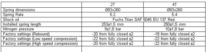
69 Press the bumper against the collar. Turn the high speed compression adjuster all the way in then back out to the pre removal setting. The factory setting is: 20 clicks out on the 2T 22 clicks out on the 4T. Turn the low speed adjuster all the way in and then back out the number of clicks recorded before removal. The factory setting is: 20 clicks out on the 2T 22 clicks out on the 4T. 69

70 Turn the rebound adjusting screw all the way in then back out the number of clicks recorded before removal. The factory setting is: 20 clicks out for the 2T 18 clicks out for the 4T. 70
71 Number of shims Size 2 Ø24 x 2,00 1 Ø22 x 0,30 1 Ø24 x 0,25 1 Ø26 x 0,25 Shim stack for the 2 stroke 1 Ø28 x 0,25 1 Ø30 x 0,25 2 Ø32 x 0,25 1 Ø34 x 0,30 1 Ø36 x 0,30 1 Ø28 x 0,10 4 Ø38 x 0,20 3 Ø44 x 0,20 3 Ø44 x 0,15 2 Ø40 x 0,15 1 Ø28 x 0,15 1 Ø44 x 0,15 1 Ø42 x 0,15 1 Ø40 x 0,15 2 Ø38 x 0,15 1 Ø36 x 0,20 1 Ø34 x 0,20 1 Ø32 x 0,20 1 Ø30 x 0,25 1 Ø28 x 0,25 1 Ø26 x 0,25 1 Ø24 x 0,30 1 Ø23 x 0,30 1 Ø24 x 2,00 71
72 Number of shims Size 1 Ø24 x 2,00 1 Ø20 x 0,30 1 Ø22 x 0,30 1 Ø24 x 0,25 1 Ø26 x 0,25 Shim stack for the 4 stroke 1 Ø28 x 0,25 1 Ø30 x 0,25 2 Ø32 x 0,25 1 Ø34 x 0,30 1 Ø36 x 0,30 1 Ø28 x 0,10 2 Ø36 x 0,15 6 Ø38 X 0,20 5 Ø44 x 0,20 3 Ø42 x 0,15 2 Ø40 x 0,15 1 Ø34 x 0,15 1 Ø44 x 0,15 1 Ø42 x 0,15 1 Ø40 x 0,15 2 Ø38 x 0,15 1 Ø36 x 0,20 1 Ø34 x 0,20 1 Ø32 x 0,20 1 Ø30 x 0,25 1 Ø28 x 0,25 1 Ø26 x 0,25 1 Ø24 x 0,25 1 Ø23 x 0,30 1 Ø24 x 2,00 72


73 Table of torque values Shock base to reservoir tank 50Nm Shock base to shock body 150Nm Compression adjuster assembly 14Nm Shaft nut 40Nm Shock clevis to shock shaft 70Nm
74
Sachs 48mm Closed Cartridge fork Service Manual
 Sachs 48mm Closed Cartridge fork Service Manual 1 Fork seal driver 2 Special soft jaws 3 Fork cap wrench 4 Rebound rod holding tool 5 Compression assembly holding tool 6 Retaining clip tool Special Tools
X-Trainer 43mm fork service manual. Beta USA, Inc This work should be performed by a trained motorcycle technician.
 X-Trainer 43mm fork service manual Beta USA, Inc. 2016 This work should be performed by a trained motorcycle technician. Table of contents Page Introduction/special tools... 2 Fork exploded view... 3 Legend.
FOX Racing Shox Bypass Technical Manual.
 FOX Racing Shox Bypass Technical Manual. The following technical manual will be using a 2.5 dia. shock with three tubes for descriptions and illustrations. Your shock may differ in the number of tubes,
Shock absorber for Automotive TTX36 P/ IL. Workshop Manual
 TTX6P TTX6IL Shock absorber for Automotive TTX6 P/ IL Workshop Manual Safety precautions General Warnings Note! The shock absorber/front fork/steering damper is an important part of the vehicle and will
Shock Absorber Rebuild Manual
 Shock Absorber Rebuild Manual Model PODIUM RC3 FOX RACING SHOX 130 Hangar Way, Watsonville, CA 95076 PHONE 800.369.7469 FAX 831.768.7026 Email: psservicemw@ridefox.com Website: www.ridefox.com Disclaimer
Workshop manual 5018 PDS Product Exploded View Disassembly & Assembling. Shock absorber 5018 PDS OEM Shock absorber 5018 PDS /2002
 Shock absorber 5018 PDS OEM 2000 Introduction 2 Exploded view 3 Disassembly shock absorber 4 Disassembly piston-rod 11 Disassembly adaptor DU-bush 15 Assembling adaptor DU-bush 17 Assembling piston-rod
Workshop manual 4618 BAVP 85 SX. Product Exploded View Disassembly & Assembling. Schok absorber 4618 BAVP 85 SX
 Schok absorber Introduction 2 Exploded view 3 Disassembly shock absorber 4 Disassembly piston rod 12 Assembling piston rod 23 Disassembly adaptor DU-bush 33 Assembling adaptor DU-bush 36 Disassembly tube
TOPAZ Service Guide. Full Service
 TOPAZ Service Guide Full Service SERVICE OVERVIEW This manual will guide you step by step performing an air service to your Topaz. Please follow each instruction carefully to achieve the best and safest
Genesis Double Adjustable Shock Assembly and Repair
 Genesis Double Adjustable Shock Assembly and Repair General Operating Description The Genesis Adjustable Shock is adjusted by moving one or both of two bypassing sliding valves. These valves slide longitudinally
Maverick American 3085 Bluff Street Boulder, CO Tel: Fax: ML7.0 SHOCK SERVICE MANUAL
 Maverick American 3085 Bluff Street Boulder, CO 80301 Tel: 303-415-0370 Fax: 303-415-0676 www.maverickamerican.com ML7.0 SHOCK SERVICE MANUAL 1. OVERVIEW 1.1. The Maverick ML7.0 rear shock is an oil damped
TK08 TUNING KIT TECHNICAL MANUAL FOR 16/26/27/28 SERIES SHOCKS Revised 6/17/14
 Tech Line: (952) 985-5675 Fax (952) 985-5679 21730 Hanover Ave. Lakeville, MN 55044 www.qa1.net www.facebook.com/qa1motorsports TK08 TUNING KIT TECHNICAL MANUAL CONTENTS UNDER PRESSURE! USE EXTREME CAUTION
Rev. B Page 1 of 7 SPEC. ASSY INST, REMOTE ADJUSTABLE PRE-LOAD (30-25XX & SA XX)
") Page 1 of 7 SPEC. ASSY INST, REMOTE ADJUSTABLE PRE-LOAD (30-25XX & SA-5057-5XX) 19 3 10 11 4 7 20 16 14 15 12 13 21 5 9 6 17 2 1 Fig. 1 Reservoir Components Fig. 2 Housing Components 30-25XX & SA-5057-5XX
Page 1 of 7 SPEC. ASSY INST, REMOTE ADJUSTABLE PRE-LOAD (30-25XX & SA-5057-5XX) 19 3 10 11 4 7 20 16 14 15 12 13 21 5 9 6 17 2 1 Fig. 1 Reservoir Components Fig. 2 Housing Components 30-25XX & SA-5057-5XX
HYDRAULICS. TX420 & & lower. Hydraulic Tandem Pump Removal. 4. Remove the LH side panel (Fig. 0388).
.") TX420 & 425 240000299 & lower 4. Remove the LH side panel (Fig. 0388). Hydraulic Tandem Pump Removal Note: Cleanliness is a key factor in a successful repair of any hydraulic system. Thoroughly clean all
TX420 & 425 240000299 & lower 4. Remove the LH side panel (Fig. 0388). Hydraulic Tandem Pump Removal Note: Cleanliness is a key factor in a successful repair of any hydraulic system. Thoroughly clean all
Maverick American 3085 Bluff Street Boulder, CO Tel: Fax: ML7.2 SHOCK SERVICE MANUAL
 Maverick American 3085 Bluff Street Boulder, CO 80301 Tel: 303-415-0370 Fax: 303-415-0676 www.maverickamerican.com ML7.2 SHOCK SERVICE MANUAL 1. OVERVIEW 1.1. The Maverick ML7.2 rear shock is an oil damped
TK08 TUNING KIT TECHNICAL MANUAL FOR 16/26/27/28 SERIES SHOCKS Revised 6/25/14 Tech Line: (952) Fax (952)
 Fax (952)") Tech Line: (952) 985-5675 Fax (952) 985-5679 21730 Hanover Ave. Lakeville, MN 55044 www.qa1.net www.facebook.com/qa1motorsports TK08 TUNING KIT TECHNICAL MANUAL CONTENTS UNDER PRESSURE! USE EXTREME CAUTION
Tech Line: (952) 985-5675 Fax (952) 985-5679 21730 Hanover Ave. Lakeville, MN 55044 www.qa1.net www.facebook.com/qa1motorsports TK08 TUNING KIT TECHNICAL MANUAL CONTENTS UNDER PRESSURE! USE EXTREME CAUTION
POWER STEERING TO INDEX POWER STEERING SYSTEM PRECAUTIONS... OPERATION CHECK... PROBLEM SYMPTOMS TABLE... VANE PUMP ASSEMBLY COMPONENTS...
 TO INDEX STEERING POWER STEERING POWER STEERING SYSTEM PRECAUTIONS.............................................. OPERATION CHECK......................................... PROBLEM SYMPTOMS TABLE.................................
Workshop manual 3612 / 4681 BAVP. Product Exploded View Disassembly & Assembling. Shock absorber
 455 Shock absorber 3612/4681 BAVP 02/2002 Shock absorber Introduction 2 Exploded view 3 Adjustment 4 Disassembly shock absorber 5 Disassembly piston-rod 7 Disassembly adaptor DU-bush 15 Disassembly tube
2014-Present Vivid Service Manual
 2014-Present Vivid Service Manual SRAM LLC WARRANTY Extent of Limited WARRANTY Except as otherwise set forth herein, SRAM warrants its products to be free from defects in materials or workmanship for a
Maintenance Information
 Form 04584058 Edition 1 November 2004 Air Impactool 2141P and 2141PSP Maintenance Information Save These Instructions Disassembly General Instructions 1. Do not disassemble the tool any further than necessary
3M Overhaul Service Kit
 SERVICE INSTRUCTIONS FOR 3M 12,000 RPM 3 in. (77 mm) RANDOM ORBITAL SANDERS 3M Overhaul Service Kit The part number 20346, 3M Overhaul Service Kit, contains all the replacement parts that naturally wear
Installation Instructions
 Preparing your vehicle to install your brake system upgrade 1. Rack the vehicle. 2. If you don t have a rack, then you must take extra safety precautions. 3. Choose a firmly packed and level ground to
1988 Chevrolet Pickup V SUSPENSION - FRONT (4WD)' 'Front Suspension - "V" Series 1988 SUSPENSION - FRONT (4WD) Front Suspension - "V" Series
' 'Front Suspension - V Series 1988 SUSPENSION - FRONT (4WD) Front Suspension - V Series") 1988 SUSPENSION - FRONT (4WD) Front Suspension - "V" Series DESCRIPTION NOTE: Vehicle serial numbers used in this article has been abbreviated for common reference to Chevrolet and GMC models. Chevrolet
1988 SUSPENSION - FRONT (4WD) Front Suspension - "V" Series DESCRIPTION NOTE: Vehicle serial numbers used in this article has been abbreviated for common reference to Chevrolet and GMC models. Chevrolet
CALIFORNIA TRIMMER MOWER MAINTENANCE MANUAL
 CALIFORNIA TRIMMER MOWER MAINTENANCE MANUAL 2 Table of Contents Section 1: General Information Page Handle Assembly Instructions 4 Maintenance All Models 6 Oil Change Procedures All Models 9 Height Adjustment
Fig Variable Speed Valve Parts
 5 DISASSEMBLY OF VARIABLE SPEED CONTROL VALVE (Seal Replacement with Control Valve in the Bobcat). Remove seat and seat plate (Fig. ).. Remove variable speed control lever linkage rod. 3. Remove temperature
Assembly Manual. 1/10th Formula 1 Car
 Assembly Manual 1/10th Formula 1 Car Center Pivot Bag 1 3374 - Center Pivot Socket 40194 - Hard Anodized Alum Pivot ball 3254-2-56 *Note - Sometimes it is helpful to slightly over-tighten the top clamp
3M Overhaul Service Kit
 SERVICE INSTRUCTIONS FOR 3M 12,000 RPM 5 in. (127 mm) and 6 in. (150 mm) RANDOM ORBITAL SANDERS 3M Overhaul Service Kit The part number 20347, 3M Overhaul Service Kit, contains all the replacement parts
Double Barrel Service Instructions Cane Creek R&D. January 2009 V2.0 1
 Double Barrel Service Instructions Cane Creek R&D January 2009 V2.0 1 Table of Contents 3. Diagnosis for Parts Needed 4. Work Flow 5. Initial Disassembly 6. Initial Disassembly Pictures 8. Reservoir Rebuild
Installation Manual TWM Performance Short throw shifter 2001 and up Hyundai Accent
 Installation Manual TWM Performance Short throw shifter 2001 and up Hyundai Accent 1. Place the vehicle on a flat surface with blocks in front and behind the wheels preventing unwanted movement. The car
Mega Air Pull-Shock Service Manual
 Mega Air Pull-Shock Service Manual K2 BIKE / NOLEEN RACING 19215 VASHON HWY. SW VASHON, WA 98070 206-463-8800 WWW.K2BIKE.COM SHOCK DISAS- SEMBLY AND ASSEMBLY In this section: Tools needed Shock Design
BRAKE SYSTEM Nissan 240SX DESCRIPTION BRAKE BLEEDING * PLEASE READ FIRST * BLEEDING PROCEDURES ADJUSTMENTS BRAKE PEDAL HEIGHT SPECS TABLE
 BRAKE SYSTEM 1990 Nissan 240SX 1990 BRAKE SYSTEMS Nissan Disc & Drum Axxess, Maxima, Pathfinder, Pickup, Pulsar NX, Sentra, Stanza, 240SX, 300ZX DESCRIPTION All brake systems are hydraulically operated
Shock Absorber Rebuild Manual
 Shock Absorber Rebuild Manual Model PODIUM X FOX RACING SHOX 130 Hangar Way, Watsonville, CA 95076 PHONE 800.369.7469 ext. 7647 FAX 831.768.7026 Email: info@foxracingshox.com Website: www.foxracingshox.com
4357 / 4860 MX Multi Adjuster
 12_234 Frontfork 4357 / 4860 MX Multi Adjuster Introduction 2 Exploded view 3 Disassembly forkleg 4 Disassembly screw-cap 15 Assembling screw-cap 17 Disassembly cartridge 18 Disassembly compression holder
FRONT FORK 2.16 GENERAL REMOVAL HOME. 4. See Figure Loosen upper and lower fork clamp pinch fasteners (1, 4).
.") FRONT FORK.6 GENERAL The XRScg model utilizes a mm fork assembly while all other models have changed to the mm fork assembly. The front fork consists of two telescoping outer tube/inner slider assemblies.
FRONT FORK.6 GENERAL The XRScg model utilizes a mm fork assembly while all other models have changed to the mm fork assembly. The front fork consists of two telescoping outer tube/inner slider assemblies.
REBUILD MANUAL FOR PRODIGY SHOCKS
 REBUILD MANUAL FOR 2.625 PRODIGY SHOCKS JUNE 2016 EDITION TOOLS NEEDED - 11/16 th wrench - FT LBS torque wrench - 3/8 ratchet with ¾ socket - ¼ ratchet with 9mm socket - 90 degree small pick - blue lok
FOR FUTURE REFERENCE SERIES 93HPS
 Hypro Series 93HPS Hydraulically Driven Wetseal Multistage Pumps Repair Manual KEEP FOR FUTURE REFERENCE Form L-1578R Rev. A SERIES 93HPS Hydraulically Driven Stainless Steel Multistage Centrifugal Pumps
70/82 SERIES SHOCK TECHNICAL MANUAL
 70/82 SERIES SHOCK TECHNICAL MANUAL Item Part No. DESCRIPTION Item Part No. DESCRIPTION 1 9007-106 Snap ring 18 9053-120 6" compression tube (82/70) 2 SIB8-101PK Bearing/snap ring kit 18 9053-115 7" compression
Steering Gearbox Disassembly
 Steering Gearbox Disassembly Steering Rack Disassembly 5. Unbend the lock washer. Before disassembling the gearbox, wash it off with solvent and a brush. Do not dip seals and O-rings in solvent. 1. Remove
Overhaul Special Tools Required
 1 of 31 Overhaul - Special Tools Required - Cylinder end seal remover attachment, 07NAD-SR3020A - Pilot collar, 07GAF-PH70100 - Valve seal ring sizing tool, 07NAG-SR3090A - Ball joint boot clip guide,
Z125 Front Fork Upgrade kits. Installation SOP
 Z125 Front Fork Upgrade kits Installation SOP Tools a. Loctite243 or Loctite2701 (Thread Locker) b. Loctite7649 (Activator) c. 33mm Hex Socket d. 17mm Hex Socket e. Shaft Clamping Tool (12mm) f. Shaft
FITTING INSTRUCTIONS YAMAHA YZF-R3
 FITTING INSTRUCTIONS YAMAHA YZF-R3 120-015-270-005 20/07/2017 ISSUE 1 2 IMPORTANT NOTES KEY NB NOTE! CAUTION! WARNING! NB NB NB The front forks are a very important part of the motorcycle and will affect
DISASSEMBLY AND ASSEMBLY
 211-02-1 Power Steering 211-02-1 DISASSEMBLY AND ASSEMBLY Steering Gear Special Tool(s) Holding Fixture, Transmission 307-003 (T57L-500-B) Special Tool(s) Installer, Worm Bearing Locknut 211-012 (T66P-3553-B)
1984 Dodge W250 PICKUP
 1984 Dodge W250 PICKUP Submodel: Engine Type: V8 Liters: 5.2 Fuel Delivery: CARB Fuel: GAS Dana 44 MODELS THROUGH 1984 2. Raise and safely support the vehicle, then remove the wheel hub and bearings as
FRONT AXLE AND SUSPENSION FA 1
 FRONT AXLE AND SUSPENSION FA1 FRONT AXLE AND SUSPENSION FA2 FRONT AXLE AND SUSPENSION Troubleshooting TROUBLESHOOTING Problem Possible cause Remedy Page Wanders/pulls Tires worn or improperly inflated
Work shop manual. Öhlins Steering damper Road & Track
 Work shop manual Öhlins Steering damper Road & Track Including: Introduction Safety instructions Dismantling the steering damper Assembling the steering damper Filling oil Introduction All of Öhlins advanced
Maintenance Information
 16573321 Edition 3 February 2014 Air Grinder Series 61H Maintenance Information Save These Instructions Product Safety Information WARNING Failure to observe the following warnings, and to avoid these
A REPAIR KIT PART NUMBER IS AVAILABLE AND CONTAINS ALL THE PARTS NORMALLY REPLACED DURING A STANDARD MAINTENANCE REPAIR.
 AZ Pump Instructions PUMP NOT RUNNING PROPERLY: Check to be sure air pressure is reaching the pump, check to be sure air filter is not clogged; clean or replace as required. Check to be sure fluid filter
Maintenance Information
 16573347 Edition 2 February 2014 Air Grinder Series 88H Maintenance Information Save These Instructions Product Safety Information WARNING Failure to observe the following warnings, and to avoid these
METERING VALVE 2" STEM GUIDED
 2" STEM GUIDED All Rights Reserved. All contents of this publication including illustrations are believed to be reliable. And while efforts have been made to ensure their accuracy, they are not to be construed
Hard Seat Fluid Pressure Regulator
 Instruction Sheet P/N 04742-02 Description The Nordson hard seat fluid pressure regulator is designed for use with abrasive coatings. The regulator body is constructed of stainless steel with a nickel-plated
Installation Manual TWM Performance Kia Forte Short Shifter
 Installation Manual TWM Performance Kia Forte 2009+ Short Shifter Begin the installation by parking on a flat surface, as you will have to engage and disengage the hand brake and shift from gears to neutral.
GATE VALVE MAINTENANCE AND ADJUSTMENT PROCEDURES
 GATE VALVE MAINTENANCE AND ADJUSTMENT PROCEDURES Valve Maintenance Manual 1 May 15, 2001 Table of Contents TABLE OF CONTENTS... 2 I. GATE AND BONNET O-RING 0.625" - 21" GATE VALVES... 3 II. BELLOWS, PNEUMATIC
2004 SERVICE MANUAL Six Six Sport Avenue Stanford, Valencia, California fax
 2004 SERVICE MANUAL Six Six Sport 28209 Avenue Stanford, Valencia, California 91355 661 257-4411 fax 661 294-4179 www.answerproducts.com Table of Contents Description Page Introduction 3 Front Suspension
GROUP 9 BOOM, ARM AND BUCKET CYLINDER
 GROUP 9 BOOM, ARM AND BUCKET CYLINDER 1. REMOVAL AND INSTALL 1) BUCKET CYLINDER (1) Removal Expand the arm and bucket fully, lower the work equipment to the ground and stop the engine. Operate the control
Maintenance Information
 04581245 Edition 2 May 2014 Air Grinder, Die Grinder and Sander Series G2 (Angle) Maintenance Information Save These Instructions Product Safety Information WARNING Failure to observe the following warnings,
Disassembly Instructions hp. Dynafile II Models: 40352, 40353
 Disassembly Instructions - 0.4 hp. Dynafile II Models: 40352, 40353 Important: Use these instructions along with the tool parts page or manual. Notice: Shut off the air supply and depress throttle lever
Slave Cylinder Weep Hole Drilling Procedure
 Slave Cylinder Weep Hole Drilling Procedure Tools Required: T20 Torx Driver T25 Torx Driver T25 Torx Bit with ¼ Ratchet Wrench 4mm Hex Key (Allen wrench) 5mm Hex Key 6mm Hex Key 8mm Hex Key 12mm Hex Key
Fluid-O-Tech ROTOFLOW ROTARY VANE PUMP REBUILD MANUAL
 Fluid-O-Tech PUMP TECHNOLOGY AT ITS BEST WWW.FLUID-O-TECH.COM Office: 161 Atwater St., Plantsville, CT 06479 Phone: (860) 276-9270 Fax: (860) 620-0193 ROTOFLOW ROTARY VANE PUMP REBUILD MANUAL 08/09 Ed.,
FORK FREE PISTON MODIFICATION 2011 HONDA CRF250R
 217 Lorain Place Los Gatos, California 95032 408.406.2089 www.smartperformanceinc.com www.spi-racing.com FORK FREE PISTON MODIFICATION 2011 HONDA CRF250R WHAT? All production versions of the 2011 HONDA
1990 SUSPENSION Front ES250, LS400
 SUSPENSION - FRONT Article Text 1990 Lexus LS 400 For Lextreme Copyright 1998 Mitchell Repair Information Company, LLC Thursday, January 29, 2004 04:56PM ARTICLE BEGINNING 1990 SUSPENSION Front ES250,
BR 43. BRAKE HYDRAULIC BRAKE BOOSTER (w/ VSC) REMOVAL
 REMOVAL") AKE HYDRAULIC AKE BOOSTER (w/ VSC) 43 REMOVAL Before starting the work, make sure that the ignition switch is OFF and depress the brake pedal more than 20 times. As high pressure is applied to the brake
AKE HYDRAULIC AKE BOOSTER (w/ VSC) 43 REMOVAL Before starting the work, make sure that the ignition switch is OFF and depress the brake pedal more than 20 times. As high pressure is applied to the brake
BETTIS SERVICE INSTRUCTIONS DISASSEMBLY AND REASSEMBLY FOR CB-SR-S SEISMIC SPRING RETURN SERIES PNEUMATIC ACTUATORS
 BETTIS SERVICE INSTRUCTIONS DISASSEMBLY AND REASSEMBLY FOR CB-SR-S SEISMIC SPRING RETURN SERIES PNEUMATIC ACTUATORS PART NUMBER: 102264 REVISION: "C" DATE: November 2000 Page 1 of 11 1.0 INTRODUCTION 1.1
2003 Dodge Pickup R DRIVE AXLES' 'Axle Shafts - Front - Ram Pickup WD DRIVE AXLES
 2002-04 DRIVE AXLES Axle Shafts - Front - Ram Pickup 1500 4WD DESCRIPTION Vehicles equipped with 4WD and C205F front axle assembly use equal length axle shaft system to deliver power from front differential
Maintenance Information
 16572679 Edition 2 May 2014 Air Drill QP Series Maintenance Information Save These Instructions Product Safety Information WARNING Failure to observe the following warnings, and to avoid these potentially
Kimray reserves the right to modify or improve the designs or specifications of such products at any time without prior notice Kimray Inc.
 TREATER VALVE All Rights Reserved. All contents of this publication including illustrations are believed to be reliable. And while efforts have been made to ensure their accuracy, they are not to be construed
Parking brake Mechanical brake acting on rear wheels
 11 Brake System 11.1 General SPECIFICATIONS EJTC0010 Master cylinder Type Tandem type I.D. mm(in.) 20.64 mm (0.813 in.) Fluid level warning sensor Provided Brake booster Type Vacuum Boosting ratio 4.0
PRESENT. VIVID AIR SERVICE MANUAL Service Manual
 2014 - PRESENT VIVID AIR SERVICE MANUAL Service Manual SRAM LLC WARRANTY EXTENT OF LIMITED WARRANTY Except as otherwise set forth herein, SRAM warrants its products to be free from defects in materials
A/C COMPRESSOR SERVICING Article Text 1991 Saab 9000 For Copyright 1997 Mitchell International Friday, October 15, :22PM
 Article Text ARTICLE BEGINNING 1991 GENERAL SERVICING Compressor Service * PLEASE READ THIS FIRST * CAUTION: When discharging air conditioning system, use only approved refrigerant recovery/recycling equipment.
Bag 1. Bag 1. Center Pivot. Center Pivot
 8 00734 01901 5 Center Pivot Bag 1 3374 - Center Pivot Socket 4019 - Alum Pivot ball 3254-2-56 Button Head *Note - Sometimes it is helpful to slightly over-tighten the top clamp screws, then work the ball
InstalL Instructions. trail-creeper 4.70 transfer case gear kit ( KIT and KIT) kit contents
 kit contents") InstalL Instructions trail-creeper 4.70 transfer case gear kit (105000-1-KIT and 105001-1-KIT) kit contents 5356 PINE AVE FRESNO, CA 93727 USA TOLL FREE: 877.4X4.TOYS WORLDWIDE: 559.252.4950 WWW.TRAIL-GEAR.COM
InstalL Instructions trail-creeper 4.70 transfer case gear kit (105000-1-KIT and 105001-1-KIT) kit contents 5356 PINE AVE FRESNO, CA 93727 USA TOLL FREE: 877.4X4.TOYS WORLDWIDE: 559.252.4950 WWW.TRAIL-GEAR.COM
INSTALLATION INSTRUCTIONS
 INSTALLATION INSTRUCTIONS REAR DISC BRAKE CONVERSION KITS A112, A112-1 & A112-93 1979-93 FORD MUSTANG with 7.5" & 8.8" AXLES Thank you for choosing STAINLESS STEEL BRAKES CORPORATION for your braking needs.
Gate Valve Maintenance & Adjustment Procedures
 Gate Valve Maintenance & Adjustment Procedures 1 Table of Contents I. GATE AND BONNET O-RING 1.5-21 GATE VALVES...3 II. BELLOWS, PNEUMATIC STANDARD 1.5-21 GATE VALVES...5 III. ACTUATOR O-RING 1.5-21 GATE
Rear End Installation and Bearing Kit - 8.8in (86-12 V8; V6)
") Rear End Installation and Bearing Kit - 8.8in (86-12 V8; 11-13 V6) Tools Required: Jack Stands 5 Floor Jack 2 Oil Pans 1 Wheel Blocks 2 Differential Oil 3 qts Friction Modifier 3 bottles Tube of Black
Rear End Installation and Bearing Kit - 8.8in (86-12 V8; 11-13 V6) Tools Required: Jack Stands 5 Floor Jack 2 Oil Pans 1 Wheel Blocks 2 Differential Oil 3 qts Friction Modifier 3 bottles Tube of Black
INSTALLATION INSTRUCTIONS
 INSTALLATION INSTRUCTIONS COOLANT EXPANSION TANK FORD FOCUS Document: 19-0151 Support: info@radiumauto.com WARNINGS: DO NOT WORK ON THE COOLANT SYSTEM WHEN THE ENGINE IS AT OPERATING TEMPERATURE. WAIT
Maintenance Information
 80234313 Edition 2 May 2014 Air Grinder, Die Grinder, Sander and Belt Sander Series G1 (Angle) Maintenance Information Save These Instructions Product Safety Information WARNING Failure to observe the
DRIVE AXLE Volvo 960 DESCRIPTION & OPERATION AXLE IDENTIFICATION DRIVE AXLES Volvo Differentials & Axle Shafts
 DRIVE AXLE 1994 Volvo 960 1994 DRIVE AXLES Volvo Differentials & Axle Shafts 960 DESCRIPTION & OPERATION All 960 station wagon models use type 1041 rear axle assembly. All 960 4-door models use type 1045
Suzuki Samurai 6.5 Transfer Case Gear Kit, KIT
 Suzuki Samurai 6.5 Transfer Case Gear Kit, 105004-3-KIT Kit Contents: Gear, 26 Spline/26 Tooth 1.0 Gear, 44 Tooth 1.0 Gear, 58 Tooth/23 Tooth 1.0 Gear, 67 Tooth/ 27 Tooth 1.0 Counter Shaft 1.0 Counter
A-320 Balanced 1st Stage
 Technical Manual A-320 Balanced 1st Stage A Manual for Repair and Maintenance Technicians View: Select Full Screen mode to use page arrows. FEATURES Extra durable satin chrome plated brass body. Fully
Maintenance Information
 16605958 Edition 2 May 2014 Air Percussive Rivet Buster Models 9001 and 11001 Maintenance Information Save These Instructions Product Safety Information WARNING Failure to observe the following warnings,
DISC BRAKE/DUAL MASTER CYLINDER CONVERSION. Tools, Equipment and Supplies Needed:
 Please take the time to read the enclosed instructions carefully. If you have any questions, call our Product Assistance personnel for clarification. It is important to note that these instructions contain
REPAIR PROCEDURES MANUAL
 REPAIR PROCEDURES MANUAL PVX Series Vane Pumps A Design Series Step-by-Step Guide to Troubleshooting and Repairing PVX Series Vane Pumps Introduction Thank you for choosing Continental Hydraulics PVX Vane
Installation Manual TWM Performance Short Shifter 2008 Mitsubishi Lancer
 Page 1 Installation Manual TWM Performance Short Shifter 2008 Mitsubishi Lancer Please Note: It is preferable to park on a flat surface, as you will have to engage and disengage the hand brake and shift
Disassembly Instructions hp. Mini-Dynafile II
 Disassembly Instructions - 0.4 hp. Mini-Dynafile II Important: Use these instructions along with the tool parts page or manual. Notice: Shut off the air supply and depress throttle lever to deplete the
Contents. 1.2 Cartridge maintenance Replacement of the cartridge gasket Piston segment replacement Piston replacement 20
 KAYABA SUSPENSION Contents KAYABA SUSPENSIONS General remarks 3 1- YOKE Exploded view 4 1.1 Maintenance of Gaskets and Rings 1.1.1 Disassembly 5 1.1.2 Assembly 8 1.2 Cartridge maintenance 1.2.1 Replacement
Front Fork Disassembling and Assembling RM-Z250L6. KAYABA Pneumatic Spring Front Fork PSF2
 Front Fork Disassembling and Assembling RM-Z250L6 KAYABA Pneumatic Spring Front Fork PSF2 RM-Z250L6 Front Fork Disassembling 1. Release air Release the air pressure by pressing the air valve with a screwdriver.
DESCRIPTION & OPERATION
 2004 BRAKES Disc - TSX DESCRIPTION & OPERATION WARNING: DO NOT use air pressure or a dry brush to clean brake assemblies. Avoid breathing brake dust. Use OSHA-approved vacuum cleaner for cleaning and collecting
BR 25 BRAKE HYDRAULIC BRAKE BOOSTER REMOVAL
 AKE HYDRAULIC AKE BOOSTER 25 REMOVAL When installing, coat the parts indicated by arrows with lithium soap base glycol grease (See page - 13). As high pressure is applied to the brake actuator tube No.
SISU DP-330 DRIVE GEAR. Maintenance Manual
 SISU DP-330 DRIVE GEAR Maintenance Manual Sisu Axles, Inc. Autotehtaantie 1 PO Box 189 Fin-13101 Hameenlinna Finland Phone +358 204 55 2999 Fax +358 204 55 2900 DP330DG.PDF (3/2007) TABLE OF CONTENTS
2013 Monarch RL Service Manual
 2013 Monarch RL Service Manual GEN.0000000004177 Rev A Copyright 2012 SRAM, LLC SRAM LLC WARRANTY Extent of Limited Warranty Except as otherwise set forth herein, SRAM warrants its products to be free
BRAKE SYSTEM TROUBLESHOOTING CHECKS AND ADJUSTMENTS MASTER CYLINDER BRAKE BOOSTER REAR BRAKE
 BR-1 BRAKE SYSTEM PRECAUTIONS TROUBLESHOOTING CHECKS AND ADJUSTMENTS MASTER CYLINDER BRAKE BOOSTER VACUUM PUMP FRONT BRAKE REAR BRAKE Drum Brake Disc Brake Parking Brake LOAD SENSING PROPORTIONING AND
Super T QR20 INSTRUCTIONS GENERAL RULES
 INSTRUCTIONS GENERAL RULES 1. Where specified, assemble and disassemble the shock absorption system using the MARZOCCHI special tools only. 2. On reassembling the suspension system, always use new seals.
SERVICE INSTRUCTIONS FOR SEAL REPLACEMENT OF POWER GEAR HYDRAULIC LEVELING LEGS
 SERVICE INSTRUCTIONS FOR SEAL REPLACEMENT OF POWER GEAR HYDRAULIC LEVELING LEGS 82-L0352 REV 8 4-27-2011 WARNING! HYDRAULIC COMPONENTS CAN CAUSE SERIOUS INJURY OR DEATH IF PROPER SAFETY PRECAUTIONS ARE
INSTALLATION INSTRUCTIONS REPAIR SEAL KIT PowerSurvivor 160E
 INSTALLATION INSTRUCTIONS REPAIR SEAL KIT PowerSurvivor 160E PURPOSE OF THE KIT The Repair Seal Kit should be installed after 500 hours of operation. It should be installed regardless of whether or not
REAR AXLE AND SUSPENSION RA 1
 REAR AXLE AND SUSPENSION RA1 RA2 REAR AXLE AND SUSPENSION Troubleshooting TROUBLESHOOTING Problem Possible cause Remedy Page Wanders/pulls Tires worn or improperly inflated Replace tires or inflate to
Maintenance Information
 16575128 Edition 2 May 2014 Air Grinder, Sander or Polisher 77A Series Maintenance Information Save These Instructions Product Safety Information Failure to observe the following warnings, and to avoid
INSTALLATION INSTRUCTIONS REPAIR SEAL KIT PowerSurvivor 40E
 INSTALLATION INSTRUCTIONS REPAIR SEAL KIT PowerSurvivor 40E PURPOSE OF THE KIT The Repair Seal Kit should be installed after 1000 hours of operation. It should be installed regardless of whether or not
INSTALLATION INSTRUCTIONS
 INSTALLATION INSTRUCTIONS REAR DISC BRAKE CONVERSION KIT A126-3 1988-98 CHEVY K1500 4WD 10" DRUMS Thank you for choosing STAINLESS STEEL BRAKES CORPORATION for your braking needs. Pleases take the time
BRAKE SYSTEM Return To Main Table of Contents
 BRAKE SYSTEM Return To Main Table of Contents GENERAL... 2 BRAKE PEDAL... 10 MASTER CYLINDER... 13 BRAKE BOOSTER... 16 BRAKE LINE... 18 PROPORTIONING VALVE... 19 FRONT DISC BRAKE... 20 REAR DRUM BRAKE...
INSTALLATION INSTRUCTIONS
 INSTALLATION INSTRUCTIONS REAR DISC CONVERSION KIT A128-4 1997-2004 JEEP WRANGLER (TJ) WITH DANA 44 AXLES (non-abs) Thank you for choosing STAINLESS STEEL BRAKES for your braking needs. Pleases take the
3.2 DRIVE TORQUE HUB. Roll, Leak and Brake Testing SECTION 3 - CHASSIS & TURNTABLE. 3-2 JLG Lift
 3.2 DRIVE TORQUE HUB Roll, Leak and Brake Testing 10 LUG PATTERN Torque-Hub units should always be roll and leak tested before disassembly and after assembly to make sure that the unit's gears, bearings
This chapter covers the location and servicing of the front brake components for the KYMCO MXU 700i and MXU 500i models.
 KYMCO MXU 500i/700i Repair Manual Brake System 9.Brake System This chapter covers the location and servicing of the front brake components for the KYMCO MXU 700i and MXU 500i models. 1.Brake Discs... 9-3