REEDSTER 125cc. F1 - F2 - F3 - F4 Versions ASSEMBLY INSTRUCTIONS & USER MANUAL
|
|
|
- Myrtle Rose
- 5 years ago
- Views:
Transcription


1 REEDSTER 125cc F1 - F2 - F3 - F4 Versions ASSEMBLY INSTRUCTIONS & USER MANUAL
2 21/01/09 2
3 INDEX N Page Section 1 DESCRIPTION OF THE Parilla REEDSTER 125cc ENGINE Main features 1.2. Engine characteristics / operation limits 1.3. Contents of the packing 1.4. Accessories 1.5. Motor identification number Section Section Section 4 1 PREPARATION & INSTALLATION OF THE ENGINE ON THE CHASSIS 6 Installation sketch of the engine on the chassis Install the water cooling system (only F3 - F4 versions) Preparation of the engine Preparation and installation of the motor-mount Install of the carburettor Charging the oil in the gear box Installation of the engine on the chassis Installation of the clutch cover with the H.T coil. Electrical connections Install the intake silencer Install the exhaust USE OF THE ENGINE 22 Charging / discharging the oil in the gear box Gasoline and oil Carburettor adjustment guide Starting and stoppping the engine Engine break-in RPM limitation Inlet silencer Exhaust system Exhaust valve adjustment guide (only for F1 - F2 - F4) Battery Warnings on the electrical system Spark-plug and thermal degree Choice of the best sprocket ratio ENGINE BASIC MAINTENANCE 37 Recommendations on the centrifugal clutch 4.2. Clutch assembly/disassembly 4.3. Gear timing schematic 4.4. Scheduled maintenance 4.5. Troubleshooting 4.6. Engine and accessories preservation 4.7. Fastener torque table Wiring diagram 3
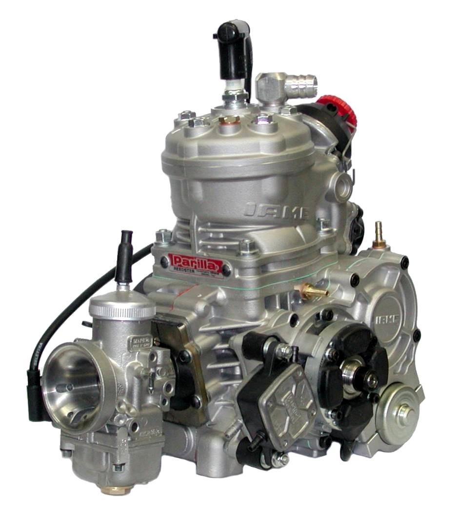
4 Section 1 - DESCRIPTION OF THE Parilla REEDSTER 125cc ENGINE 1.1 MAIN FEATURES The Parilla Reedster engine is the result of the decennial racing experience of IAME and it contains many technological and construction innovations which enable the engine to achieve both high performance and guarantee excellent reliability and endurance characteristics. This engine has been designed and tuned for powering the karts for both hobby and agonistic racing on closed tracks destined for this specific purposes. When designing the engine we have considered the technical solutions already adopted for the high performance engines and the experience acquired with the "TaG" series engines (Touch and Go). The Reedster engine has been homologated in 2006 according to the CIK/FIA international rules and it is available in 4 versions: F1, F2, F3 ed F4. This engine is a 2 stroke single cylinder. The thermic group and crankcase are in aluminium alloy. The pressed-in liner is made of centrifuged cast iron and machined from the full to guarantee the best possible stability sliding homogeneity and precision. The head is secured by 5 screws to the cylinder which is fitted to the crankcase by 4 studbolts. The crankshaft is of the built up type and supported by two ball bearings. It is of steel alloy hardened and tempered, as is the connecting rod which is machined from the full. The rod runs on roller bearings on both ends. The crankcase houses a balance shaft, driven by two gears, which rotates opposite to the crankshaft thus reducing the engine vibrations. The digital ignition with capacitive discharge, is fed by a magneto which generates the spark energy for the starting of the engine, guarantees the advance timing through an integrated pick-up and recharges the battery. The ignition includes a digital electronic unit, the stator-rotor, the starter relay, the H.T. coil, a switch key assembly, and of course the wiring harness (with a 5A fuse) which connects the whole system. The electronic box, which controls the advance, the rev. limitation imposed by the CIK/FIA rules and the engine start/stop logic also integrates the voltage regulator and the ignition control circuit. The starter relay (Solid type SSR), protected from short-circuits and overloads, supplies the power for the electric starter and is controlled by the electronic unit. The spark is generated also without a battery; it is therefore possible, in case of emergency to start the engine with an external starter unit. When the starter key is in the "RUN" position, the electric starter activates a Bendix type gear which engages the starter ring assembled on the clutch. The engine is provided with a dry centrifugal clutch with low maintenance and with interchangeable sprocket. 4
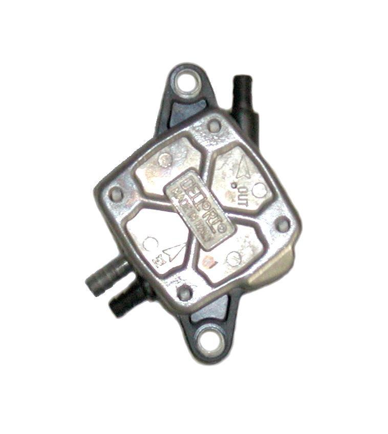
5 The battery (12 V - 7.2Ah) is a sealed, no maintenance battery and is supplied already pre-assembled in a support box, which can be easily adapted to all existing chassis. Both a throttle carburettor and a float chamber carburettor (on the F4 version), can be fitted on the engine. In this last case, the engine is provided with a fuel pump. A power-valve is fitted on the cylinder exhaust duct (with the exception of the KF3 version) to optimize the low range performance. The exhaust system, included in the supply, is already tuned and optimized to guarantee the best efficiency. The water-pump, is integrated in the engine and the water cooling system involves both the thermic group and the crankcase. The engine (only F3 and F4) is supplied with a kit which includes the homologated radiator, the water hoses, the thermostat and the fixing supports on the chassis. 1.2 CHARACTERISTICS OF THE ENGINE OPERATION LIMITS The characteristics of the engine are the following : Cycle : Original cubic capacity: Original bore: Max. theoretical bore: Stroke: Lubrification: Induction: Carburettor: Cooling : Ignition : Battery charge: Electric start: Clutch: OTTO / 2 stroke cc (125cc max.) mm mm mm Fuel / oil mix 4% (25:1) Reed valve in the crankcase Diaphragm or float chamber (only F4) Water, forced Digital electronic / with integral rev. limiter With integral generator 12V/0.30 Kw starter Automatic, dry,centrifugal Operational limits: Max. RPM: 14000rpm (F3 e F4) / 15000rpm (F2) / 16000rpm (F1) Min. water temperature: Max. water temperature: 45 C 65 C Never exceed the above limits ; no obligation of IAME exists in case the above limits are exceeded. 5
6 1.3 CONTENTS OF THE PACKING Each Parilla Reedster 125cc engine is supplied with the under shown components and accessories: EXHAUST SYSTEM Power valve on the exhaust duct Exhaust springs Exhaust fitting with spacer Exhaust system Additional exhaust silencer INDUCTION SYSTEM Dell Orto VHSH30 CS carburettor Fuel pump Inlet silencer ELECTRICAL SYSTEM Battery 12 V Battery support Battery strip Battery fixing clamps Electronic box Starting relay H.T. coil Starting Key assembly Fixing clamps NGK BR 10 EG spark plug Spark plug cap Wiring harness MISCELLANEOUS Clutch cover Dual-Lock fixing strap WATER COOLING SYSTEM Homologated radiator Radiator support kit Water hoses kit Thermostat with three-way fitting Quantity 1 (excepted F3) (only F3) 1 (only F4) 1 (only F4) 1 (only F4) (only F3 e F4) 1 (only F3 e F4) 1 (only F3 e F4) 1 (only F3 e F4) 6


7 1.4 ACCESSORIES EXHAUST SYSTEM NGK SPARK PLUG BATTERY WITH SUPPORT CLUTCH COVER / H.T. COIL COMPLETE ELECTRIC SYSTEM CARBURETTOR FUEL PUMP THERMOSTAT RADIATOR SUPPORT KIT INLET SILENCER RADIATOR WATER HOSES KIT 7
. The number normally includes a letter followed by 4 digits (there can be exceptions in some special cases).")

8 1.5 MOTOR IDENTIFICATION NUMBER The official motor identification number can be found stamped on the lower front right part of the crankcase, near the reed group (see fig.). The number normally includes a letter followed by 4 digits (there can be exceptions in some special cases). Other numbers stamped on the crankcase or on other surfaces of the motor refer to various manufacturing processes and do not identify the engine. NOTE: In case of need for spares and when contacting the IAME Support Centers, please always refer to the Motor Identification Number and to the motor model. 8
9 Section 2 - PREPARATION AND INSTALLATION OF THE ENGINE ON THE CHASSIS NOTE: In case the engine is supplied already assembled on the chassis, it is at care of the assembler to follow these instructions. The final customer, in this case, can skip this section and can start reading from section 3. Whenever the engine or a component is disassembled, it is necessary to always follow the under shown instructions for proper reassembly. 2.1 INSTALLATION SKETCH OF THE ENGINE ON THE CHASSIS 9
.")
10 2.2 INSTALL THE WATER COOLING SYSTEM (only for F3 - F4) BEFORE INSTALLING THE RADIATOR PREASSEMBLE THE FOLLOWING COMPONENTS 1 INSTALL THE 4 RUBBER DAMPENERS IN THE RADIATOR FIXING HOLES (SEE FIG.1). RUBBER DAMPENERS Fig.1 10
 NOTE: OIL THE BRACKET ENDS AND THE DAMPENER HOLES FOR AN EASIER INSERTION. RADIATOR SUPPORT BRACKET Fig.")
11 2 - PLACE THE RADIATOR SUPPORT BRACKET BETWEEN THE RADIATOR FIXINGS BY TILTING ONE END AND INSERTING IT THROUGH THE RUBBER DAMPENERS (SEE FIG.2) NOTE: OIL THE BRACKET ENDS AND THE DAMPENER HOLES FOR AN EASIER INSERTION. RADIATOR SUPPORT BRACKET Fig.2 11
. Fig.3 Fig.")
.")
. DO NOT TIGHTEN THE SCREW (SEE FIG.5). Fig.5 RADIAT.")
 (N 1 M8x65 SCREW).")
12 - COMPLETE INSERTION OF THE RADIATOR SUPPORT BRACKET IN THE RUBBER DAMPENERS (SEE FIG.3 AND 4). Fig.3 Fig.4 3 FIX THE RADIATOR SUPPORT BRACKET INSERTING ALSO THE RADIATOR FIXING BRACKET (RADIATOR CAP SIDE N 1 SCREW M6x90 AND N 1 SCREW M6x85 WITH NUT). INSTALL THE "Z" SHAPE BRACKET ON THE RADIATOR SUPPORT BRACKET TONGUE (N 1 SCREW M8X45 WITH NUT). DO NOT TIGHTEN THE SCREW (SEE FIG.5). Fig.5 RADIAT. FIXING BRACKET Z SHAPE BRACKET BRACK M8X45 SCREW M6X90 SCREW 4 M6X85 SCREW FIX THE RADIATOR Z SHAPE LOWER BRACKET ON THE CHASSIS RAIL FIXING (BRAKE SIDE) (N 1 M8x65 SCREW). DO NOT TIGHTEN THE SCREW (SEE FIG.6). N.B.: EVENTUALLY USE THE OUTFIT BUSHINGS TO ADJUST THE RADIATOR POSITION. M8X65 SCREW Fig.6 12
 Fig.")


. T FITTING BEFORE STARTING THE ENGINE, FOLLOW THESE RECOMMENDATIONS: Unscrew the cap on the radiator and loosen the breather plug on the engine head.")
13 5 PLACE THE RADIATOR SO THAT THE HOLE ON THE RADIATOR FIXING BRACKET MATCHES WITH ONE OF THE UPPER HOLES ON THE BEARING SUPPORT BOX (SEE FIG.7). ONCE YOU FIND THE CORRECT POSITION, TIGHTEN THE M8x45 SCREW AND M8X65 ON THE LOWER Z SHAPE BRACKET THUS FIXING THE RADIATOR. TIGHTEN AT 8 10 Nm (70 90 in-lb) Fig.7 6 THE KIT INCLUDES TWO RUBBER HOSES OF WHICH THE LONGEST ONE HAS TO BE CUT IN 4 DIFFERENT LENGTH HOSES (SEE FIG.8). - CONNECT THE 1 HOSE BETWEEN THE RADIATOR INLET AND THE THERMOSTAT OUTLET. - CONNECT THE 2 HOSE BETWEEN THE RADIATOR OUTLET AND THE "T" FITTING. - CONNECT THE 3 HOSE, THE SHORTEST ONE IN THE KIT, BETWEEN THE SMALLEST THERMOSTAT OUTLET AND THE T" FITTING. - CONNECT THE 4 HOSE BETWEEN THE ENGINE INLET FITTING AND THE T FITTING. - CONNECT THE 5 HOSE BETWEEN THE ENGINE OUTLET AND THE THERMOSTAT INLET. FASTEN WITH STEEL CLAMPS ALL THE HOSE ENDS Fig.8 THE THERMOSTAT MUST BE POSITIONED SO THAT THE REAR UNION FOR THE RECYCLING COOL WATER IS PROPERLY FIXED TO THE "T" FITTING ON THE HOSE CONNECTING THE RADIATOR OUTLET TO THE ENGINE INLET FITTING (SEE FIG.9). T FITTING BEFORE STARTING THE ENGINE, FOLLOW THESE RECOMMENDATIONS: Unscrew the cap on the radiator and loosen the breather plug on the engine head. Fill the radiator until the water comes out from the plug (there is no air in the system now) and the radiator is completely filled. Tighten the cap (the system contains approx. 2 lt. of water). It is advisable to put a small cup to recover water from the breather on the radiator cap to avoid fluid leakages on the track. After the engine run-in, check the water level in the radiator and top up if necessary. 13
. NOTE: THE ENGINE IS SUPPLIED WITH THE EXHAUST FITTING AND SPACER ALREADY PRE-INSTALLED. Fig.1 2.3.")

14 2.3 INITIAL PREPARATION OF THE ENGINE ON THE EXHAUST POWER VALVE THERE IS A WARNING TAG TO REMIND THE USER THAT THE GEAR BOX MUST BE FILLED WITH OIL BEFORE STARTING THE ENGINE (SEE FIG.1). NOTE: THE ENGINE IS SUPPLIED WITH THE EXHAUST FITTING AND SPACER ALREADY PRE-INSTALLED. Fig WHEN THE SHIPMENT IS MADE, THE ENGINE INNER PARTS ARE PROTECTED BY PLASTIC PLUGS WHICH MUST BE REMOVED BEFORE INSTALLING THE ENGINE (SEE FIG.2). - SPARK PLUG HOLE PLUG - WATER FITTING PLUGS - EXHAUST FITTING PLUG - CARBURETTOR FITTING PLUG Fig PREPARATION AND INSTALLATION OF THE MOTOR-MOUNT NOTE: ALL DIMENSIONS ARE IN MILLIMETERS DRILL 4 HOLES ( mm DIAM.) IN THE ENGINE MOUNT. NOTE: PREFERABLY USE A FLAT MOTOR MOUNT. MOTOR MOUNT HORIZONTAL VIEW 14

 2.5.1 REMOVE THE PLASTIC PLUG FROM THE INLET MANIFOLD.")
. HEXAGONAL WRENCH 5 mm WHEN REPLACING THE CARB.")

15 2.4.2 INSTALL THE MOTOR-MOUNT: MAKE SURE TO USE M8 ALLEN SCREWS WITH A LENGTH SUCH AS TO ENGAGÈ, IN THE CRANKCASE A THREADED LENGTH OF APPROX mm (THE SCREWS MUST PROTRUDE FROM THE PLATE FOR APPROX 16 19mm - SEE FIG. 3 AND DRAWING PAGE 10) 4 M8 ALLEN SCREWS TORQUE AT Nm ( in-lb) 6 mm HEXAGONAL WRENCH Fig INSTALL THE CARBURETTOR K F1 - F2 - F3 VERSIONS (THROTTLE CARB) REMOVE THE PLASTIC PLUG FROM THE INLET MANIFOLD. ATTENTON: MAKE SURE THAT THE PRESS URE HOLE ON THE GASKET IS NOT PLUGGED. Fig INSTALL THE CARBURETTOR. N. 2 NUTS M6 TORQUE AT A 6 10 Nm (50 90 in-lb) (SEE FIG. 5). HEXAGONAL WRENCH 5 mm WHEN REPLACING THE CARB. GASKET ALWAYS MAKE SURE THAT THE GASKET IS INSTALLED SO THAT THE PRESSURE HOLES ON THE INLET MANIFOLD AND ON THE INLET CARB. ARE NOT PLUGGED AND MATCH. OTHERWISE THE ENGINE WON'T START. NOTE: WHEN USING CARBS. PROVIDED WITH AN EXTERNAL PRESSURE INTAKE (NOT ON THE FIXING FLANGE) IT WILL BE NECESSARY TO REMOVE THE "PLUGGING" SCREW ON THE LEFT SIDE OF THE INLET DUCT (SEE ARROW) AND INSTALL THE PROPER MANIFOLD. Fig.5 15
 INSTALL THE VIBRATION")

 OUT 10mm PIPE WRENCH PRESS IN Fig.7 2.5.")
. Fig.")
16 F4 VERSION (FLOAT CHAMBER CARB) Fig INSTALLATION OF THE FUEL PUMP (IF NOT ALREADY ASSEMBLED IN ORIGIN) INSTALL THE VIBRATION DAMPENERS ON THE GEAR BOX COVER I (SEE FIG. 6). PLACE THE FUEL PUMP WITH THE OUTLET FITTING TOWARDS THE UPPER SIDE AND TORQUE THE SELF-LOCKING NUTS M6. TORQUE AT 6 10 Nm (50 90 in-lb) (SEE FIG.7) OUT 10mm PIPE WRENCH PRESS IN Fig INSTALLATION OF THE CARBURETTOR REMOVE THE PLASTIC PLUG FROM THE INLET MANIFOLD AND INSTALL THE CARB. THEN TIGHTEN THE STEEL CLAMP (SEE FIG. 8). Fig.8 CONNECT BY MEANS OF A TUBE (FUEL PIPE TYPE) THE PRESSURE INTAKE FITTING ON THE CRANKCASE AND THE PUMP PRESSURE INTAKE. BY MEANS OF ANOTHER TUBE CONNECT THE FUEL PUMP OUTLET TO THE CARB. MANIFOLD. (SEE FIG.9). Fig.9 16
. 12 POINT WRENCH - 11mm Fig.")


17 2.6 CHARGING THE OIL IN THE GEAR BOX REMOVE THE OIL BREATHER PLUG (REAR PART OF THE ENGINE) (SEE FIG.10). 12 POINT WRENCH - 11mm Fig.10 REMOVE THE OIL LEVEL PLUG (FRONT PART OF THE ENGINE) (SEE FIG.11). HEXAGONAL WRENCH - 4mm Fig FILL WITH 33cc IAME EP100 OIL THE GEAR BOX (SEE FIG.12). NOTE: IF THE LEVEL IS CORRECT YOU WILL SEE A LIGHT OUTCOME OF OIL FROM THE OIL LEVEL PLUG. INSTALL THE OIL LEVEL PLUG TORQUE AT A Nm INSTALL THE OIL BREATHER FITTING TORQUE AT Nm Fig.12 17


. Fig.14 2.7.3 INSTALL THE CHAIN (SEE FIG. 15).")
.")
18 2.7 INSTALLATION OF THE ENGINE ON THE CHASSIS PLACE THE ENGINE ON THE TWO SIDE RAILS AND SECURE THE MOTOR-MOUNT WITH THE TWO CLAMPS (SEE FIG.13) SUGGESTION: DO NOT TIGHTEN THOROUGHLY THE CLAMPS UNTIL THE CHAIN IS NOT INSTALLED AND PROPERLY ALIGNED. Fig CHECK THE ALIGNMENT OF THE ENGINE SPROCKET AND THE AXLE SPROCKET WITH A STRAIGHT EDGE (SEE FIG.14). Fig INSTALL THE CHAIN (SEE FIG. 15). (PITCH: 7.775) Fig MOVE THE ENGINE ON THE RAILS AND OPTIMIZE THE CHAIN TENSION. THE CHAIN PLAY MUST BE OF APPROX. 15mm, MEASURED IN THE SHOWN POINT (SEE FIG. 16). 15mm TIGHTEN THE CLAMP SCREWS HEXAGONAL WRENCH 8mm Fig.16 18
 HEXAGONAL WRENCH - 5 mm MAKE SURE THAT THE COPPER GROUND CABLE ALWAYS CONNECTS THE H.T. COIL WITH THE ENGINE.")
. TORQUE THE 3 SCREWS M6 AT 8 10 Nm ( 70 90 in.lb) HEXAGONAL WRENCH - 5 mm Fig.18 19")
19 2.8 INSTALLATION OF THE CLUTCH COVER WITH H.T. COIL CONNECT THE H.T. COIL GROUND CABLE TO THE CRANKCASE BY MEANS OF THE M6 SCREW ON THE FRONT FOOT (SEE FIG.17). TORQUE AT 8 10 Nm (70 90 in. lb) HEXAGONAL WRENCH - 5 mm MAKE SURE THAT THE COPPER GROUND CABLE ALWAYS CONNECTS THE H.T. COIL WITH THE ENGINE. AN INADEQUATE GROUNDING COULD DAMAGE THE IGNITION SYSTEM BEYOND REPAIR. Fig.17 THE POSITION OF THE H.T. COIL HAS BEEN CHOSEN TO BE AS FAR AS POSSIBLE FROM THE EXHAUST AS THE EXCESSIVE HEAT COULD DAMAGE THE H.T. COIL, BEYOND REPAIR INSTALL THE CLUTCH COVER WITH H.T. COIL (SEE FIG.18). TORQUE THE 3 SCREWS M6 AT 8 10 Nm ( in.lb) HEXAGONAL WRENCH - 5 mm Fig.18 19
. 2.9.2 PLACE THE BATTERY SUPPORT BOX IN THE FRONT OF THE CHASSIS (UNDER THE FRONT PANEL FAIRING) AND FIX IT WITH THE CLAMPS TO THE LOWER STEERING COLUMN")
 PIPE WRENCH - 10mm THE SUPPORT BOX MUST BE FIXED WITH AT LEAST ONE BOLT FOR EACH CLAMP.")


20 2.9 Fig.19 ELECTRICAL CONNECTIONS (refer to the attached electrical schematic) NOTE : For a correct installation follow the under shown instructions INSERT THE BATTERY STRAP IN THE BATTERY SUPPORT BOX (SEE FIG.19) PLACE THE BATTERY SUPPORT BOX IN THE FRONT OF THE CHASSIS (UNDER THE FRONT PANEL FAIRING) AND FIX IT WITH THE CLAMPS TO THE LOWER STEERING COLUMN SUPPORT TUBES (M6x25 SCREWS - SEE FIG.20). TORQUE AT 8 10 Nm (70 90 in. Lb) PIPE WRENCH - 10mm THE SUPPORT BOX MUST BE FIXED WITH AT LEAST ONE BOLT FOR EACH CLAMP. FIX THE BOX WITH MORE THAN ONE BOLT DEPENDING ON THE TYPE OF CHASSIS. NOTE: THE BOX AND CLAMPS ARE PROVIDED WITH VARIOUS HOLES TO ALLOW INSTALLATION ON ALL KIND OF CHASSIS INSERT THE BATTERY IN THE BOX AND FASTEN IT WITH THE BATTERY STRAP (SEE FIG.21). POSITION THE BATTERY TERMINALS AS SHOWN ON THE FIGURE. Fig.20 Fig.21 ATTENTION : PAY ATTENTION NOT TO SHORT-CIRCUIT THE BATTERY TERMINALS AS THE BATTERY COULD BE DAMAGED BEYOND REPAIR PLACE THE WIRING HARNESS STARTING FROM THE ENGINE, ALONG THE RAILS, THE STEERING COLUMN AND UNDER THE FRONT PANEL FAIRING (SEE FIG.22). TIGHTEN WITH PLASTIC CLAMPS. Fig.22 NEVER LET THE HARNESS GET IN TOUCH WITH THE GROUND OR WITH ROTATING PARTS AS IT COULD BE DAMAGED BEYOND REPAIR. 20


 THIS OPERATION IS VERY IMPORTANT, OTHERWISE THE RESIDUAL ENGINE VIBRATIONS COULD DAMAGE THE ELECTRIC")
. Fig.26 TORQUE AT 8 10 Nm (70 90 in.")
21 2.9.5 CONNECT THE TERMINAL FROM THE IGNITION WITH THE 8 POLES TERMINAL ON THE HARNESS (SEE FIG.23). -CONNECT THE ONE WAY TERMINAL FROM THE ELECTRIC STARTER WITH THE ONE WAY TERMINAL ON THE HARNESS. (SEE FIG.24). MAKE SURE THAT THE FIXING TONGUES ARE PROPERLY INSERTED TO GUARANTEE THE BEST POSSIBLE CONNECTION OF THE TERMINALS. Fig.23 Fig CHECK THAT THE PLASTIC CLAMP FASTENS THE CABLE FROM THE ELECTRIC STARTER TO THE STARTER BODY (SEE FIG.25) THIS OPERATION IS VERY IMPORTANT, OTHERWISE THE RESIDUAL ENGINE VIBRATIONS COULD DAMAGE THE ELECTRIC STARTER INNER CONNECTIONS BEYOND REPAIR FASTEN THE 2 TERMINALS GROUND CABLES WITH EYELET, TO THE H.T. COIL WITH THE M6 FIXING NUT (SEE FIG.26). Fig.26 TORQUE AT 8 10 Nm (70 90 in. lb) PIPE WRENCH - 10mm THIS OPERATION IS EXTREMELY IMPORTANT AS AN UNCERTAIN GROUNDING COULD DAMAGE THE ELECTRONIC BOX BEYOND REPAIR. 21
. FASTEN THE H.T. COIL CABLE WITH A PLASTIC CLAMP")


 - RED = F1 vers. (16000 RPM max.) Fig.29")
22 2.9.8 CONNECT THE H.T COIL CABLE TO THE HARNESS TERMINAL (SEE FIG.27). FASTEN THE H.T. COIL CABLE WITH A PLASTIC CLAMP TO AVOID THAT EVENTUAL VIBRATIONS MIGHT DISCONNECT THE TERMINALS (SEE FIG.28). Fig.27 Fig CUT THE DUAL-LOCK FIXING STRAP AND ATTACH IT TO THE REAR OF THE ELECTRONIC BOX, THE STARTER FUSE AND THE RELAY (SEE FIG.29). ELECTRONIC BOX. RELAY NOTE: THE COLOUR OF THE ELECTRONIC BOX CHANGES ACCORDING TO THE ENGINE VERSION AND TO THE REV. LIMITER SETTING: - YELLOW = F4 vers. (14000 RPM max.) - BLUE = F3 vers. (14000 RPM max.) - GREEN = F2 vers. (15000 RPM max.) - RED = F1 vers. (16000 RPM max.) Fig CONNECT THE ELECTRONIC BOX TO THE 20 POLE CONNECTOR ON THE HARNESS (SEE FIG.30). ATTENTON: MAKE SURE THAT THE FIXING TONGUES ARE PROPERLY INSERTED TO GUARANTEE THE BEST POSSIBLE CONNECTION OF THE TERMINALS. Fig.30 22
; AND INSTALL THE STARTER ASSEMBLY (SEE FIG.32).")
.")

.")
23 CONNECT THE STARTER RELAY TO THE 4 POLES CONNECTOR ON THE HARNESS (SEE FIG.31). Fig DRILL A Ø 22mm HOLE IN THE SIDE EDGE OF THE FRONT PANEL FAIRING (ENGINE SIDE); AND INSTALL THE STARTER ASSEMBLY (SEE FIG.32). SECURE THE STARTER ASSEMBLY WITH THE THREADED LOCKING NUT. Ø 22mm CONNECT THE STARTER ASSEMBLY CONNECTOR TO THE 8 POLES CONNECTOR ON THE HARNESS (SEE FIG.33). MAKE SURE THAT THE FIXING TONGUE OF THE CONNECTOR IS PROPERLY INSERTED TO GUARANTEE THE BEST POSSIBLE CONNECTION OF THE TERMINALS ATTACH THE DUAL-LOCK STRAP UNDER THE FAIRING (CLOSE TO THE STEERING COLUMN) AND INSTALL THE ELECTRONIC BOX AND THE STARTER RELAY (SEE FIG. 34). NOTE: CLEAN AND DEGREASE THE SURFACE WHERE THE STRAP IS TO BE PLACED TO GUARANTEE THE BEST POSSIBLE ATTACHMENT. FOR A BETTER FASTENING, SECURE THE ELECTRONIC BOX AND RELAY WITH SCREWS, BY USING THE EXPRESSLY MADE HOLES FOR THIS PURPOSE. 23
. 2.9.")
. 2.9.")
.")

24 DRILL THE FAIRING AND FASTEN THE HARNESS WITH PLASTIC CLAMPS (SEE FIG.35) DRILL THE FAIRING (CLOSE TO THE BATTERY) AND PLACE THE FUSE-HOLDER BY MEANS OF THE 2 HOOKS OF THE JUNCTION BLOCK (SEE FIG.36) PLACE THE BATTERY TERMINALS OF THE HARNESS UNDER THE STRAP (SEE FIG. 37). SUGGESTION: NEVER CONNECT THE BATTERY UNTIL YOU ARE READY TO START THE ENGINE. SEAL THE BATTERY TERMINALS WITH PLASTIC TAPE TO AVOID THAT EVENTUAL VIBRATIONS MIGHT DISCONNECT THE TERMINALS SCREW THE SPARK CAP ON THE H.T. COIL CABLE (SEE FIG. 38). 24
 INSTALL THE CAP ON THE SPARK PLUG. Fig.")

 AND THAT THEY ARE NOT PLUGGED. -TIGHTEN THE CLAMP ON THE CARB.")

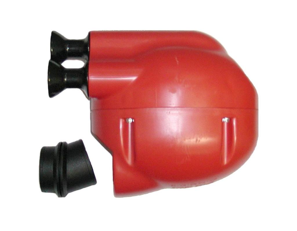
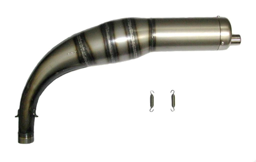
25 FIX THE CAP TO THE H.T. CABLE WITH A PLASTIC CLAMP (SEE FIG.39). INSTALL THE SPARK PLUG. TORQUE AT Nm ( in-lb) INSTALL THE CAP ON THE SPARK PLUG. Fig.39 NOTE: FOR A CORRECT DIGITAL IGNITION OPERATION, THE CAP AND / OR THE SPARK PLUG, MUST BE OF THE RESISTIVE TYPE AND HAVE A RESISTIVITY OF 5 KΩ MIN INSTALL THE INTAKE SILENCER Fig.40 -MAKE SURE THAT THE FILTER HAS THE INLET HOLES TOWARDS THE UPPER SIDE (SEE FIG.40) AND THAT THEY ARE NOT PLUGGED. -TIGHTEN THE CLAMP ON THE CARB. AND FIX THE FILTER TO THE CHASSIS SIDE RAILS WITH A "CRADDLE" SHAPE SUPPORT (SEE FIG.41). Fig INSTALL THE EXHAUST NOTE: SEE SECTION 3.8 FOR RECOMMENDATIONS ON THE EXHAUST - INSTALL THE EXHAUST SILENCER ON THE ENGINE FITTING AND SECURE IT WITH THE 2 SPRINGS (SEE FIG.42). - FIX THE SILENCER ON THE CHASSIS "CRADDLE " SUPPORT. Fig.42 THE ENGINE IS READY TO BE STARTED 25

26 Section 3 - USE OF THE ENGINE 3.1 CHARGING / DISCHARGING THE OIL IN THE GEARBOX The engine is supplied without oil in the ge arbox. Before starting the engine fill the gearbox with IAME EP100 motor oil. Starting the engine with a dry gearbox will damage t he gears beyond repair - charging the gearbox: Put the engine in horizontal position, unscrew the oil plug (n 1 on the picture), and oil level plug (n 2 on the picture), fill with oil until it comes out from the oil level plug (approx. oil quantity in the gearbox = 33 cc). Exclusively use IAME EP100 motor oil - check the oil level The oil level can be checked by placing the engine in horizontal position and unscrewing the oil level plug. If the level is correct you should see a light outcome of oil, otherwise top up. - discharge the oil Unscrew the oil level plug (n 3 on the picture) and loosen the oil drain plug to let air in the gearbox GASOLINE AND OIL Use leaded (super) or unleaded (green) gasoline, mixed with oil at 4%. It is possible to use synthetic oils or oils containing Castor oil. As Castor Oils create gummy residues it is necessary to check and clean, at least every 10 hrs, the piston and the head. Our experience dictates use of oils, such as: SHELL ADVANCE RACING X ELF HTX 909 Once the fuel tank is filled, make sure that the gasoline reaches the carburettor (or the pump - F4 version -) before starting the engine. Never use the electric starter to suck the gasoline as this could discharge the battery. SUGGESTION: Disconnect the plastic tube on the carb. and the vent tube on the tank and pressurize the vent tube, until the gasoline comes out from the tube on the carb. Make sure that there is no air in the tube. Connect the tube on the carb. and on the vent. 26
: F1 engine vers.: IBEA L7 Ø30 carburettor H = 1.10 (1 turn and 10 ) F2 engine vers.: IBEA L6 Ø24 carburettor H = 1.")
27 3.3 CARBURETTOR ADJUSTMENT GUIDE 1 T.O.* ( L ) LOW SPEED FUEL MIXTURE ( I ) IDLE ADJUSTMENT SCREW REGOLAZIONE * ( H ) HIGH SPEED FUEL MIXTURE RICH LEAN 1 ¼ T.O. ¾ T.O. 1 ½ T.O. T.O. = TURNS OPEN Hereinafter are shown some basic carbs. settings according to the engine version (after engine run-in): F1 engine vers.: IBEA L7 Ø30 carburettor H = 1.10 (1 turn and 10 ) F2 engine vers.: IBEA L6 Ø24 carburettor H = 1.10 (1 turn and 10 ) F3 engine vers.: TRYTON F3 Ø20 carburettor H = 0.35 (35 ) L = 1.45 (1 turn and 45 ) L = 1.25 (1 turn and 25 ) L = 1.30 (1 turn and 30 ) Based on various factors as altitude, ambient temperature etc. it might be necessary to reset the carb. setting to optimize the performance of the engine. - - Never lean too much as lean mixture will overheat the engine and cause seizure. Do not force H or L closed. It may damage the precision machined orifice and render the carb. inserviceable. The adjustment of the screw must be performed with warm engine. 27

28 F4 engine vers: DELL ORTO VHSH30 CS CARBURETTOR The above settings are those prescribed by IAME for the carb. Dell'Orto VHSH 30 CS, installed on the Parilla REEDSTER engine - in the F4 version. The above table shows the reference setting, for the proper engine operation under different temperature, altitude and atmospheric pressure conditions Should you need an optimized carb. setting, for all atmospheric conditions, it will be necessary to adjust the setting for a better mixture strength according to the track characteristics and ambient conditions. In case of a high level setting, for which a specific experience is required, it is impossible to give instructions in a few words. Our target is to give here simple instructions for setting the best adjustment, according to the operation conditions. As a rule, we consider three ranges of operation: the idle RPM and low RPM, attainable with throttle lever slightly opened; the mid. RPM or intermediate RPM, attainable with intermediate opening of the throttle lever and the max RPM, attainable with max. opening throttle lever. In a float chamber carburettor, such as this carburettor, specific devices are available to check the carburetion at each RPM range of operation; each of these devices intervenes on a specific area as described hereinafter, even if there is no clear distinction among the different areas. The idle RPM can be adjusted by means of the "A screw " (see fig.1), which intervenes on the throttle valve by slightly lifting or and lowering it. It is necessary to turn clockwise to increase the RPM, and turn counterclockwise to decrease it. The carburetion at idle RPM can be set by means of : Fig.1 A The idle jet in the float chamber The idle emulsion tube, located above the respective jet The air mixture idle screw Generally, for standard adjustments, the emulsion tube is not concerned. A richer mixture can be obtained by increasing the idle "L" jet size (see fig.2), and a leaner mixture by decreasing the above size. The idle jet can be reached removing the carb. float chamber. A richer carburetion is attainable by turning the air screw "B" clockwise (see fig.1); on the contrary, by unscrewing, you get a leaner carburetion. It is suggested to gradually perform the adjustment by 5 10' turns per time. Then check the result. The adjustment of the carburation at mid range is performed by means of: H The conical needle The needle jet the conical needle acts as a shutter on the needle jet, and its axial position is determined by the throttle gas opening. Thanks to its particular conical configuration, when the throttle opens gradually, the needle gradually releases the spray nozzle hole and regulates the gasoline flow. L Fig. is go2 The conical needle and the spray nozzle have been chosen to satisfy most of the conditions, and as a rule, it not necessary to replace them with others having different characteristics. The carburetion setting is performed by lifting or lowering the needle vs. the throttle gas. 28
. On the picture is shown the basic needle adjustment.")

, we get a richer carburetion, and vice versa, a leaner one, by decreasing the jet size. To reach to the max. Jet, screw out the central plug on the float chamber (see fig.")
29 Fig.3 We will get a richer carburetion by lifting the needle, that is, by moving down the retainer clip to a lower notch; and on the contrary, a leaner carburetion is achieved lowering the needle, that is by lifting the retainer clip to a higher notch (see fig.3). On the picture is shown the basic needle adjustment. To reach the conical needle proceed as follow: screw out the upper locking ring on the carb., then pull off the throttle gas together with the needle, release the throttle cable, and screw out the fixing screw on the throttle gas. The adjustment of the carburetion at top RPM is mainly performed by means of: Fig.4 The max. jet By increasing the "H" max jet size (see fig.2), we get a richer carburetion, and vice versa, a leaner one, by decreasing the jet size. To reach to the max. Jet, screw out the central plug on the float chamber (see fig.4), or disassemble the float chamber itself. As anticipated, there is no clear distinction among the areas of influence of the different components, as they interact and influence each other. As a matter of fact, the max. jet affects, not only the carburetion, at wide open throttle gas, but also the whole mid range carburetion, even if less sensibly vs. the needle position; indirectly, the needle position slightly influences the carburetion, at completely opened throttle. In the same way, when the throttle is slightly opened, the effects of the min. jet and the air screw superimpose with the effect of the conical needle position. To properly adjust the carburetion according to the ambient conditions, we are giving some indicative parameters, to adapt the max. jet size as a function of the variation of the ambient temperature and the altitude at which the engine is operating. As you know, carburetion, that is, the exact quantity of fuel to be mixed to a given quantity of air, is influenced by atmospheric factors, such as temperature and pressure. The more the temperature drops, the more the air density increases and consequently, there will be more molecules of gas in the same volume. As the carb. mixes always the same fuel quantity this would be insufficient and the carb. will provide a leaner mixture. In these conditions, as you are aware, when operating with a leaner mixture, the engine runs the following risks: overheating, insufficient lubrication, detonation, seizure; for this reason the carburettor setting must be adjusted by increasing the max. jet size by about 2-3 points for every 6 C external temperature drop. Of course, on the contrary, the more the temperature rises, the more the carburetion becomes richer and gives origin to less critical consequences than the ones experienced with a leaner carburetion. So, also in this case, it is suggested to optimize the carb. setting, by decreasing the max. jet size by about 2-3 points for every 6 C external temperature increase. The variation of the atmospheric pressure, which is significant when varying the altitude at which the engine is operating, gives origin to such a phenomenon; by decreasing the altitude, the atmospheric pressure increases, consequently in the same air volume sucked by the engine, more molecules of gas are present Therefore, in this case too, a carb. adjustment is required; increase the max. jet size by about 2-3 points for every 350m altitude decrease. 29


30 On the contrary, by increasing the altitude it is necessary to reduce the max. jet size by about 2-3 points for every 350m altitude Increase. The above data are only indicative, as many factors influence the carburetion and only a few among them are ponderable. With these indications we wish to give the owner a general guide line and avoid damaging the engine under variations of ambient conditions which make the carburetion substantially leaner. A fine carb. adjustment will always have to be made according to the experience and to the tests performed on the track. As completion of this guide line, here are a few general recommendations:. the carburettor is provided with an enrichment system for starting the engine ( "C" lever - see fig.5) when the engine is cold and/or when the engine has been kept out of operation for a certain time. To get the max efficiency this device must be used with gas throttle closed or slightly opened. A few seconds after the engine has been started, shut the enrichment to avoid system to avoid flooding the carburettor. Fig.5 C The real problems which could be experienced with these carburettors are exclusively connected to the fuel feeding. The fuel feeding is regulated by the floater-valve system located in the float chamber. In case impurities (particles) are present in the fuel, these might prevent the admission valve from properly closing; the level in the float chamber will increase and the exceeding fuel is discharged through the carb. breather. In this case, it is necessary to disassemble the chamber, remove the floaters and the admission valve, then clean with compressed air (see fig.6-7). In case of puncture of one or both floaters, the admission valve cannot be closed, and so the exceeding fuel overflows through the breathers. In this case it is necessary to disassemble the float chamber, check the fuel feeding into the floaters and replace them with others with same weight. In case the engine has to remain out of operation for a long period, the fuel admission valve could get stuck (either on opening or on closing position) due to presence of incrustations. In the first case, the same fuel overflowing phenomenon from the carb. breathers is experienced, in the second, the engine does not start for insufficient feeding. It is therefore necessary to disassemble the float chamber, check if there is fuel inside, remove incrustations and re-establish the proper fuel admission through the floater-valve assembly. Fig.6 Fig.7 30
31 3.4 STARTING AND STOPPING THE ENGINE Starting is achieved by the starting key. This is a 3 position key: STOP (key can be removed) 2- RUN 3- START 1- STOP RUN START In STOP position, the battery is disconnected and the engine stop signal is sent to the electronic box. In RUN position, the battery is connected to the system and the stop signal is removed. In START position the battery is always connected and the electric starter operation signal is sent to the electronic box. The START position can be stable or recovered by means of a return spring. In this case, once the engine is started, the spring automatically brings the key back to the RUN position. The starting key assembly is provided with two original keys. It is recommended to separate the keys and to keep one in a protected place. In case of loss of both keys, it is necessary to replace the complete assembly. The starting procedure, from STOP position, is as follows: A) Turn the key to RUN position (this connects the battery). B) Turn the key to START position to start the engine (the electric starter is immediately disengaged when turning the key to RUN position, or when the electronic box detects an engine RPM higher than 2000 RPM). C) When the engine is started the key can be left both in START position (key assembly without return spring) or in RUN position. We suggest for practical reasons to always turn the key to RUN position; this allows with a single tripping to stop the engine (STOP position) or to restart it in case the engine is stopped (START position). Note: - in case the engine is stopped with the key in START position (key assembly without return spring), to restart it, turn the key in RUN position and then again to START position to activate the electric starter. - with the key in RUN or START position and if the engine is stopped, to start the engine, an external starter unit can also be used. In case the engine cannot be started within 5 seconds (check that fuel gets to the carb.) interrupt and try again after 15 seconds. Short and frequent tries are better than long ones. 31
32 To stop the engine, proceed as follows: A) Turn the key in STOP position, both from RUN position (1 tripping) or from START position (2 trippings). 3.5 ENGINE BREAK-IN The break-in of the engine must be performed following a few fundamental recommendations: 1. Adjust the carburetion. Start with a basic adjustment on the rich side. 2. Warm the engine gradually for about 5 minutes, at half throttle, making a few laps at low speed, gently closing and opening the carb. throttle (if a tachometer is installed never exceed RPM). Never keep the same RPM for a long time. 3. Increase the speed for 5 minutes (at throttle ¾ opening). Never keep the same RPM for a long time. 4. Increase the speed for 5 minutes at max. speed on the twisty parts and making the engine rich at half straight (cover with the hand, for an instant, the holes on the air filter, keeping the throttle wide open). Once the break-in is over and the engine is cold, check the torque of the exhaust header nuts as, during the break-in, the nuts tend to become loose (refer to the attached table). 3.6 RPM LIMITATION The electronic box integrates an RPM limiter which prevents the engine from exceeding RPMs for both F3 and F4 versions, RPM for F2 vers. and RPM for F1. vers. The limit of RPMs cannot be exceeded, otherwise the engine could be damaged by the extremely high RPM. Do not keep the engine for a long time at the RPM at which the limiter is operating. This would cause malfunctions on the induction and damage the reed valve. When choosing the sprocket ratio always refer to maximum limit so that the RPM limiter only intervenes on the longer straights on the track. 3.7 INLET SILENCER Make sure that the inlet holes on the filter are towards the front side of kart and that they are not plugged. Make sure that the clamp on the carb. is not loose and that the filter is well fastened to the rail side chassis, by means of a craddle" support. Once a while, clean the inside from oil deposits. If necessary remove the rubber filter union and clean it with gasoline or solvent. 32
33 3.8 EXHAUST SYSTEM Before every test, make sure that the springs are well hooked and properly in place. In case of breakage, replace the broken spring. Never race the kart without the 2 springs in place, as otherwise the exhaust pipe could vibrate beyond control. Every hrs, open the pipe end and make sure that the holes on the internal counter cone are not plugged. The equipment muffler has already been tuned to achieve the best possible performance. Having fixed a sprocket ratio, it could be necessary to improve the engine performance either at low or at high RPM. This could be achieved by modifying the suggested exhaust length, removing or adding the spacers placed behind the exhaust header. 5mm SPACER In general, by shortening the total length, an improvement at high RPM is achieved, and vice versa, by lengthening it, the low RPM is improved. When testing, though, never exceed in lengthening or shortening by more than 5mm per time. 3.9 EXHAUST VALVE ADJUSTMENT GUIDE - - (ONLY F1 - F2 - F4) The engine is provided with a pneumatic power-valve on the exhaust duct to improve the performance at low RPM. The power valve can be adjusted by turning the ring nut or by replacing the retaining spring inside the power valve. The basic setting varies according to the spring type and is achieved by turning clockwise the ring nut until limit stop and then unscrewing and counting the number of notches necessary until you get an optimal setting. Ø 0.9mm / L=45mm spring wire: from the limit stop, unscrew the ring nut by 2 notches (all versions). Ø 1mm / L=43mm spring wire : from the limit stop, unscrew the ring nut by 15 notches (all versions). Starting from 2009 cylinder version: Ø 1mm / L=34.5mm spring wire: from the limit stop, unscrew the ring nut by 14 notches (KF2 version). Ø 1mm / L=34.5mm spring wire: from the limit stop, unscrew the ring nut by 20 notches (KF1 version). 33
34 Ø0.9mm / L=45mm: 2 NOTCHES Ø1mm / L=43mm: 15 NOTCHES Starting from 2009 cylinder version Ø1mm / L=34.5mm: 14 NOTCHES (KF2) Ø1mm / L=34.5mm: 20 NOTCHES (KF1) NOTE ON THE PNEUMATIC POWER- VALVE OPERATION The power-valve chokes the exhaust port opening at low RPM, and achieves a more limited port timing diagram and a reduced exhaust port. The power valve function is to optimize the engine performance up to a given RPM. Above this RPM, the power-valve will open to re-establish the original port timing, in the mid-top RPM range. For the REEDSTER engine, the opening RPM is set at approx RPM. In addition to the above, we can give a few recommendations to the driver for the proper adjustment of the power-valve. In any case, such a procedure can also be followed to for the best opening RPM setting. If the power-valve opens too soon, that is, below 9500 RPM, the driver will feel a power output discontinuity, just under this speed limit. In this case screw (clockwise) the adjustment ring nut on the power-valve, one notch at a time, until the phenomenon disappears. If the power-valve opens too late, that is, over 9500 RPM, the driver will feel a power output discontinuity, above this speed. In this case, unscrew (ccw) the adjustment ring nut on the power-valve, one notch at a time, until the phenomenon disappears. The adjustment of the opening speed must be performed when the engine is warm and working at standard operation temperature. When the engine is cold, as it normally happens between two working sessions, the oil residuals, which are present between the exhaust valve and its seat, reach a higher viscosity and this prevents the valve operation and delays its opening. This situation can be experienced when the engine has not reached its operating temperature, and this situation can be corrected, by slightly unscrewing the adjustment ring nut. We suggest though not to modify the setting, as, once the engine reaches the proper working temperature, the oil becomes more fluid and the valve starts working again properly ;no other intervention is required. 34
35 3.10 BATTERY The battery (12 V 7.2 Ah) is sealed and without maintenance. In order to lengthen the battery life, it is necessary though to follow a few recommendations: When the tension drops below 12.6V it is necessary to recharge Max. allowed recharging current is 1.8A. The ideal recharge is achieved with an average current of 0.8 the battery 1 A. (recharging time approx. 10 hrs.) at an ambient temperature between 0 and 40 C. An overcharge or an extremely qui ck charge with excessive current could damage the battery (the battery would tend to swell). Choose a battery charger with the following characteristics: Feed tension: 90/250 Vac 50/60 Hz Outlet tension: 15 V full charge 13.8 stand-by Max. outlet tension: 2A full charge During transportation and/or storage the battery could loose its charge due to self discharge (0.1% max per day). Fully recharge battery before use. Always connect the - (negativ e) terminal before and the pole + (positive terminal) after. Always disconnect the battery in opposite order. Recharge the battery at least once every 6 months. Never put the battery in contact with solvents, oils, plastics, or rags containing such elements, as they may damage the external case. Never press or bend or overheat (by welding) the battery terminals. Other recommendations Pay attention not to have free fires upon or around the Never short-circuit the terminals. Never open the battery or throw it in the fire. In case the electrolyte (diluted with Sulphuric Acid) battery. gets in contact with skin or clothes, wash immediately with water. In case it gets in touch with eyes, wash and apply for medical assistance. Carefully check the external case of battery and replace in case of breakages, swellings of the case or of battery cover. Before use, clean the battery from dust and check that the terminals are not oxidized or damaged. When the battery comes to an end never throw it in the garbage but deliver it to an authorized disposer WARNINGS ON THE ELECTRICAL SYSTEM 35
36 We are listing the main warnings on the electrical system. Please keep this in mind during the whole life of the engine If these prescriptions are not followed the electrical system and the engine could be damaged beyond repair. No obligation of IAME exists in this case. Please turn the key to STOP position every time the engine is stopped. If the key is left in RUN position for a long time, even if the engine is stopped, the battery would be discharged completely. 2) Never disconnect the ground cables with eyelets (ground cables) when the engine is in operation. 3) Disconnecting the battery when the engine is in operation DOES NOT increase the engine performance. Vice versa, the ignition advance could become very irregular at low RPM thus reducing the performance. 4) To fasten the eyelet terminal (groundings) of the wiring harness always use flat or open washers. Never use tab washers. 5) When disconnecting the connectors, always press the fixing tongues. Always pull the connectors to disconnect. NEVER PULL THE CABLES. 6) The electronic box and the starting relay must always be installed with their connectors towards the bottom to avoid back water, dampness or dirt in the connector body. 7) Always correctly fix the H.T. coil with both screws, make sure that the laminations pack on the H.T. coil is connected to the engine with the grounding cable (copper cable or screws). The eyelet connector must be directly in contact with the lamination pack on the H.T. coil. 8) Never use H.T. coils different than the original coil on the engine. Use of a different coil may cause damages to the electronic box. 9) The digital assembly needs use of a resistive spark plug cap or spark plug. The resistor value must be equal or higher than 5 Kohm. Avoid use of resistive H.T. cables. 10) The electric system is protected against the battery polarity reversal. When reversing the connectors on the battery, the protection circuit activates the fuse as soon as the key is in RUN o START position. The fuse must then be replaced. 1) 11) Replace the fuse after having disconnected both terminals on the battery. Only use 5A strip fuse. Use of fuses with higher amperage might damage the electronic box whenever the battery polarity is reversed. 12) Only use sealed lead type batteries as specified by IAME. Only use 12V. batteries. 13) Always disconnect the battery from the electrical system when recharging the battery with an external battery charger, otherwise the internal voltage regulator could be damaged. 14) DO NOT connect batteries in parallel; this might cause explosions and damages to the operator. The recharge of the battery, in normal conditions (battery charged, proper starting, etc ) is guaranteed by the electrical system. A few minutes of engine in operation is sufficient to recover the energy lost when starting the engine. In case the battery must feed other users (tachometer telemetry, etc ),first contact IAME to check the recharge capacity of the system. 16) Modifications, interventions and additions to the original electric system might cause malfunctions. No obligation of IAME exists in this case. 15) 36
37 3.12 SPARK PLUG AND THERMAL DEGREE The engine is supplied with a standard NGK BR10EG, which represents a good compromise between the needs of a good break-in and the racing needs in normal conditions. Use of different spark plugs is possible and, as a general information, we are attaching a correspondence list among spare plugs of other brands, based on thermal degree which represents the capacity of the spark plug to dissipate the internal heat. The colour of the various parts of the spark plug more exposed to the combustion flames gives a good indication on the adequacy of the thermal degree and on the carburetion. It is necessary though to understand which of the two parameters has to be changed and only the experience tells how to identify the most proper thermal degree of a spark plug as lean or rich mixtures can generate the same final look which can also be achieved with a hot or cold spark plug. See table: An excessive warm spark plug shows the symptoms, listed aside. Always use a warmer than standard sp ark plug with cold or rainy climate.. A correct thermal degree shows: An excessively cold symptoms, listed aside. spark plug shows Extremely clear colour, porous look and calcification of the electrodes and of the internal insulation. Irregularities in the ignition, pre-ignition and detonation with tendency to perforate the top of the piston. Note: some of these symptoms can be achieved with lean mixtures. Colour of the insulator end from yellow grey to dark brown for mixtures respectively lean or rich. the Insulator end and electrodes covered with black shady soot. Ignition difficulties. Note: a wet or oily electrode could also mean an excessively rich mixture. Always use a colder than standard spark plug with hot climates. COMPARISON TABLE BASED ON THE THERMAL DEGREE HOT BOSCH WO8CS WO7CS WO6CS NGK BR9EG BR10EG BR11EG CHAMPION N54R N52R COLD 37
38 3.13 CHOICE OF THE BEST SPROCKET RATIO The life of an engine depends on many factors but most of all, upon the speed at which the engine is operated. If an engine is normally operated at speed higher than what recommended by the manufacturer, the wears and stress of the various components (con-rod, roller cages, bearings etc.) will be such as to drastically reduce the life of the engine itself. It is therefore important that the user respect the operating limits imposed by the manufacturer. The operation limit for the Reedster is RPM for F3 and F4, RPM for F2 and RPM for F1 (the RPM limiter is calibrated at these values). Never exceed the above limit. No obligation of IAME exists in case the above limit is exceeded. In case the user wishes to optimize, on the track, the sprocket ratio in order to achieve the best possible performance without abusing the engine, follow the under shown recommendations. The engines are supplied with a 12 teeth sprocket (pitch mm.), but 11 and 13 teeth sprockets are available as accessories. Table 1 shows the various ratios between the sprocket on the axle and the engine sprocket given the different axle and engine sprockets. Tab.1 Sprocket ratio Teeth n axle sprocket Sprocket ratio Teeth n - engine sprocket ,55 6,64 6,73 6,82 6,91 7,00 7,09 7,18 7,27 7,36 7,45 6 6,08 6,17 6,25 6,33 6,42 6,5 6,58 6,67 6,75 6,83 5,54 5,61 5,69 5,77 5,85 5,92 6 6,08 6,15 6,23 6,3 Teeth n axle sprocket Teeth n - engine sprocket ,55 7,64 7,73 7,82 7,91 8,00 8,09 8,18 8,27 8,36 6,92 7 7,08 7,17 7,25 7,33 7,42 7,5 7,58 7,67 6,38 6,46 6,54 6,61 6,69 6,77 6,85 6,92 7 7,08 To achieve the max RPM speed of RPM, the table N 2 has been prepared. To achieve the max RPM speed of RPM, the table N 3 has been prepared. To achieve the max RPM speed of RPM, the table N 4 has been prepared. SUGGESTION: During the track tests we recommend use of a tachometer recording the max. obtained engine RPM. Use spark plug caps or spark plugs with a min. resistance of 5KΩ to avoid eventual interferences between the engine ignition and the tachometer and/or telemetry. 38

 a sprocket ratio from 7,08 and 6,96 should be used (having used during the tests, a sprocket ratio of 6,5 and having achieved 12500 RPM).")
39 The following example should clarify the procedure for optimization of sprocket ratio : assume to use an engine, in the F4 version with a Z=12 sprocket, and that during the preliminary track tests a Z=78 teeth axle sprocket has been used. From the table 1 with Z=12 as engine sprocket and Z=78 on the axle sprocket, a ratio of 6,5 is found. Make a few laps on the track and let us assume that you read a max. of engine RPM. From table 2, to achieve a max. RPM of (operating limit for F4 engine version) a sprocket ratio from 7,08 and 6,96 should be used (having used during the tests, a sprocket ratio of 6,5 and having achieved RPM). From table 1, with these values, a sprocket ratio of 12:85 or 12:83 should be used or having a Z=11 on the engine sprocket, a ratio of 11:77 should be used. SPROCKET RATIO TO ACHIEVE MAX RPM (F3 e F4) Max Engine RPM during tests Sprocket ratio 39
 Max.")
40 SPROCKET RATIO TO ACHIEVE MAX RPM (F2) Max. engine RPM during tests Sprocket ratio SPROCKET RATIO TO ACHIEVE MAX RPM (F1) Max. engine RPM during tests Sprocket ratio 40
41 Section 4 - ENGINE BASIC MAINTENANCE 4.1 RECOMMENDATIONS ON CENTRIFUGAL CLUTCH The engine has a low maintenance dry centrifugal clutch. The following prescriptions if carefully followed, will allow a long clutch life. When starting the engine, make sure that the brake pedal is fully pressed to avoid sudden accelerations. Once the kart is started, avoid useless accelerations which can overheat and deteriorate the clutch. Oil the chain before each test. When lubricating the chain avoid the oil penetration through the lightening holes of the drum. Therefore do not spray oil close to the sprocket, but inside the lower branch of the chain near the sprocket on the axle. In case of lubricant penetration into the clutch, the clutch dragging speed will slightly increase. This overheats and deteriorates the components of the clutch. In case this happens by accident stop the engine immediately and, degrease the clutch drum and hub with specific solvents. Check the sprocket status after each race or test and replace if necessary. A bad alignment of the sprocket with the axle sprocket or the lack of oil will damage the sprocket beyond repair. Check the clutch: Every 5 hours of use. When metallic noises are heard inside the clutch. If the kart dragging speed exceeds 5000 RPM. Every time the clutch has overheated (presence of smoke o smell of burning). To check the clutch, you must remove the clutch cover and the clutch drum. Replace the clutch: Whenever the thickness of the friction material (see drawing) is lower than 1.5mm on point A of the clutch, or, if the body diameter is lower than 82.5mm. Whenever the external friction material in the A portion of the clutch is very rough (wear or degradation of the friction material due to overheating). In case the friction material has been totally worn out and there has been a metal contact between the clutch body and the clutch drum, it is necessary to replace the clutch drum. 41
42 4.2 INSTRUCTIONS FOR THE DISASSEMBLY/ASSEMBLY OF THE CLUTCH the following operations can be performed by a skilled mechanic, under the condition to have available the dedicated tools shown on the text; otherwise it is necessary to apply to an Authorized Service Center. Refer to the following drawing during the operations. 1 Drum nut 2 External washer 3 Roller cage 4 Sprocket Screw Clutch drum Internal washer Locking nut 9 Clutch body 10 Starter ring 11 Screw OPERATIONS TOOLS Clutch disassembly 1. Remove the clutch cover (3 screws M6). 2. Remove the spark plug and replace with special tool to prevent crankshaft from turning. Piston fitting: P.N Remove nut (1 screw M10x1). 12 point wrench 17 mm 4. Remove the external washer, the drum complete with roller cage, the internal washer. 5. Remove the special tool from the head and using the clutch wrench, remove the 20x1 nut and the starter ring. Allen Wrench 5mm T type Clutch wrench: P.N. S mm socket turn clockwise as the nut has the left thread. 6. Apply the clutch puller on clutch and remove the clutch, with starter ring. 7. Remove the starter ring (3 screws M6) 42 Clutch puller :P.N C 12 point wrench 19mm. 12 point wrench 10 mm
43 Before assembling the clutch, wash with diluent the shaft taper, the connecting hole on the clutch body, the clutch drum and the starter ring. Install clutch 1. Install the starter ring on the clutch body by matching the three holes and the dragging pin (3 screws TE M6) make sure to always install the Ø 7 mm dragging pin as otherwise, the eventual kick backs, could break the screws. 2. Install the clutch body and the starter ring. 12 point wrench 10 mm (Torque at 10 Nm) (90 in-lb) (apply Loctite on the threads) Apply Loctite 641 for coaxial lockings. 3. Install the clutch body fixing nut and starter ring, using the clutch wrench. turn counterclockwise as nut has left thread. 4. Install inner washer. Locking tool: P.N. S884 Allen wrench - 30 mm. (torque at Nm) install washer with bevel towards the crankshaft. Clean the roller cage and grease it before installing it on the crankshaft. 5. Install the clutch drum and the external washer. install washer with bevel towards the crankshaft. 6. Install the piston fitting to prevent the shaft from turning and install the clutch cover (M10x1 nut) 7. Install the clutch cover (3 screws M 6) Piston fitting: P.N mm socket (torque at Nm) ( in-lb) Allen wrench 5 mm- T type. (torque at 8 10 Nm) (70 90 in lb) 4.3 GEAR TIMING SCHEMATIC In case of assembly of the gears which drive the balance shaft, assembly must be performed following the timing schematic shown below. An incorrect assembly of the gears can cause a malfunction in the vibration reduction system and damage the engine beyond repair. 43

44 4.4 SCHEDULED MAINTENANCE Following some simple maintenance recommendations will allow the engine to perform more reliably and have a longer life. SCHEDULE Before using COMPONENTS Exhaust fitting springs Muffler Engine sprocket Engine chain After use Every 4 hrs Every 5 10 hrs Every 10 hrs. Every 20 hrs. Battery Cables and connectors Grounding of cables and coil Engine mounts and clamps Battery Chain Engine Piston Bendix assembly ACTIONS AND COMMENTS Check status Check status and fixing Check wear Check alignment with axle sprocket Check wear, tensioning and oil chain Check status and charge Check status and connectors Check status and connectors Check torques disconnect Oil chain External cleaning Replace Remove cover (see fig.) and clean internally Exhaust muffler Inlet silencer Engine head Power-valve Clutch Remove muffler end, clean Open, clean Open, clean Open, clean Open check status of parts Piston and con-rod assembly crankshaft Bearings Bearings / balance shaft Gears Balance shaft Check and replace worn parts Check and replace worn parts Check and replace worn parts Check and replace worn parts Check and replace worn parts Check and replace worn parts 44
45 4.5 TROUBLESHOOTING Below are some common faults, their probable causes and suggested remedy. FAULTS PROBABLE CAUSES Starter will not crank when Bad connections on starter cables turning the key to RUN position Bad grounding Interruption on fuse Damaged cables Battery connections loose Battery discharged Starter failure Electronic box or relay failure REMEDY Check and tighten Check connections and tighten Replace (5A) strip fuse, after checking for eventual reversal of battery polarity) Replace Check and tighten Recharge or replace battery Check Apply to authorized Service Centers Check connectors. Starter cranks but engine won't Bad cable connection start when turning the key in RUN position. Bad H.T coil connections or coil Check / replace failure Bad H.T. coil grounding Check grounding Electronic box or ignition failure Apply to authorized Service Centers Wet spark plug Replace Malfunction on induction system Check status and connection on fuel pipe Replace gaskets and membranes on carburettor Check reed petals. Replace if necessary. Engine starts but it stops after a Bad cable connection Check stator connector few seconds when turning the key in RUN position. Electronic box or ignition failure Apply to authorized Service Centers Bad carburettor adjustment Check carburettor adjustment (see ( screw I) sect. 3.3) The starter cranks also after the Electronic box failure Apply to authorized Service engine is running. Centers Starter relay remains excited Replace starter relay Rough idle Bad carburettor adjustment Check carburettor adjustment (see (screw l) sect. 3.3) Drop in engine performance Bad compression Check piston Bad carb. adjustment Check carburettor adjustment (see sect. 3.3) Insufficient fuel flow Check fuel flow lines and inlet filter Dirty inlet silencer Check and clean Bruning smell, smoke Clutch overheating Check clutch (see sect. 4.1) Clutch engages at too high RPM Excessive wear of friction material Check clutch (see sect. 4.1) Exhaust too noisy Oil leakage between hub and drum Clean and degrease carefully Damaged muffler Check and replace if necessary Damaged or lost springs Damaged exhaust header 45
 Disconnect carburettor and clean it Seal with tape the engine, inlet and exhaust The external of the engine must be cleaned. Spray with protective oil, the steel parts subject to oxidation.")
46 4.6 ENGINE AND ACCESSORIES PRESERVATION When engine is to remain out of operation for a long period it must be preserved as follows: Disconnect battery and recharge it periodically (see sect. 3.10) Disconnect carburettor and clean it Seal with tape the engine, inlet and exhaust The external of the engine must be cleaned. Spray with protective oil, the steel parts subject to oxidation. Keep the engine in a dry ambient. 4.7 TORQUE VALUES 46
BASIC INSTRUCTIONS SHIFTER KZ1 / KZ2 e X30 SHIFTER-TaG
 BASIC INSTRUCTIONS SHIFTER KZ1 / KZ2 e X30 SHIFTER-TaG FEEDING: by fuel mixture 98NO (min. 95NO) and 4% oil (CIK homologated). ATTENTION: the engine is supplied without oil in the gearbox. GEARBOX OIL
125cc LEOPARD TaG engine 2003
 125cc LEOPARD TaG engine 2003 ASSEMBLY INSTRUCTIONS and USER MANUAL 18/10/02 mod. C MAN-016 D INDEX GENERAL DESCRIPTION OF THE "LEOPARD" ENGINE CHARACTERISTICS OF THE "LEOPARD" ENGINE OPERATIONAL LIMITS
X30 125cc Spec. EU ASSEMBLY INSTRUCTIONS AND USER MANUAL MAN-089
 X30 125cc Spec. EU ASSEMBLY INSTRUCTIONS AND USER MANUAL MAN-089 FEEDING Fuel mixture 98 RON and oil 5% (20:1) minimum. Engine oil CIK homologated. Our experience dictates use of oils, such as: - WLADOIL
125cc RL - TaG ASSEMBLY INSTRUCTIONS & USER MANUAL
 125cc RL - TaG ASSEMBLY INSTRUCTIONS & USER MANUAL - 1 - MAN-043E MAN-043E ENG - ENG I N D E X PAGE Section 1 DESCRIPTION OF THE IAME X30 125cc RL - TaG ENGINE 01 1.1. Main features 01 1.2. Characteristics
BASIC MANUAL X30 125CC MAN-80
 BASIC MANUAL X30 125CC FEEDING Fuel mixture 98 RON and oil 5% (20:1) minimum. Engine oil CIK homologated. Our experience dictates use of oils, such as: - WLADOIL K 2T; - ELF HTX 909; - ELF HTX 976; - LEXOIL
BASIC MANUAL X30 SUPER 175CC MAN-78
 BASIC MANUAL X30 SUPER 175CC FEEDING Fuel mixture 98 RON and 4,5% oil (22:1 - CIK homologated) Our experience dictates use of oils, such as: - WLADOIL K 2T; - ELF HTX 909; - ELF HTX 976; - SHELL ADVANCE
ASSEMBLY INSTRUCTIONS
 C 125cc LEOPARD TaG engine 2003 ASSEMBLY INSTRUCTIONS and USER MANUAL 18/10/02 mod. INDEX GENERAL DESCRIPTION OF THE "LEOPARD" ENGINE CHARACTERISTICS OF THE "LEOPARD" ENGINE OPERATIONAL LIMITS 1- Contents
REEDSTER 125cc. versions: F1 - F2 - F3 - F4 OVERHAULING MANUAL
 REEDSTER 125cc versions: F1 - F2 - F3 - F4 OVERHAULING MANUAL 07/11/07 21/01/2009 1 INDEX Page 1. - REEDSTER 125cc ENGINE DISASSEMBLY 1 2. - CRANKSHAFT DISASSEMBLY / ASSEMBLY 13 2.1 - CRANKSHAFT DISASSEMBLY
INSTALLATION MANUAL. REEDJET 100cc -TaG MAN-72/C - USA
 INSTALLATION MANUAL REEDJET 100cc -TaG MAN-72/C - USA I N D E X PAGE General description of engine 01 Engine features / Operational limits 02 Contents of packaging 02 Accessories 03 Engine identification
OVERHAUL MANUAL 28/09/05 mod. A 1 MAN-044 ING
 OVERHAUL MANUAL 28/09/05 mod. A 1 INDEX Page 1. - PARILLA X30 125cc RL TaG ENGINE DISASSEMBY 1 2. - CRANKSHAFT DISASSEMBLY/ ASSEMBLY 10 2.1- CRANKSHAFT DISASSEMBLY 10 2.2- CRANKSHAFT ASSEMBLY 12 3. - PARILLA
INDEX TECHNICAL SPECIFICATIONS 2 SPECIAL TOOLS 3-4 PERIODIC MAINTENANCE 5 LUBRICANTS 6 TROUBLESHOOTING 7-14 TIGHTENING TORQUE TABLE 15
 INDEX TECHNICAL SPECIFICATIONS 2 SPECIAL TOOLS 3-4 PERIODIC MAINTENANCE 5 LUBRICANTS 6 TROUBLESHOOTING 7-14 TIGHTENING TORQUE TABLE 15 ENGINE DISASSEMBLY 16-24 ENGINE REASSEMBLY 25-37 SPECIAL 3-SHOE CLUTCH
REEDJET AUS 100cc TaG
 REEDJET AUS 100cc TaG INSTALLATION MANUAL 01/11/04 MAN-033 GENERAL DESCRIPTION OF ENGINE This engine of the "TaG" series (Touch and Go) has been expressly designed and developed to power Karts for hobby
X30 CHALLENGE INTERNATIONAL TECHNICAL REGULATIONS 2017 PART 2 ENGINES
 X30 CHALLENGE INTERNATIONAL TECHNICAL REGULATIONS 2017 PART 2 ENGINES X30 CHALLENGE INTERNATIONAL TECHNICAL REGULATIONS 2017 - PART 2: ENGINES ARTICLE 1 - ENGINE IAME X30 125cc RL TaG - X30 SENIOR & X30
Ciscomotors C-Max All types of models
 Ciscomotors C-Max All types of models SiMPLIFIED MAINTENANCE MANUAL All information in this publication is based on latest specification s product available at the time of approval for printing. CISCOMOTORS
MANUAL INDEX. Page 1. LEOPARD 125cc ENGINE DISASSEMBLY CRANKSHAFT DISASSEMBLY/ ASSEMBLY CRANKSHAFT DISASSEMBLY 8
 MANUAL INDEX Page 1. LEOPARD 125cc ENGINE DISASSEMBLY 1 2. - CRANKSHAFT DISASSEMBLY/ ASSEMBLY 8 2.1- CRANKSHAFT DISASSEMBLY 8 2.2- CRANKSHAFT ASSEMBLY 10 3. LEOPARD 125cc ASSEMBLY 13 4. - CHECK CYLINDER
WORKSHOP MANUAL. Chainsaw GS35 GS350 MT350 MT3500
 WORKSHOP MANUAL Chainsaw GS35 GS350 MT350 MT3500 General failures analysis Suggested tools I. Emak tool kit II. Compression tester: to check thermal group III. Electronic tachometer: for 2 and 4 stroke
HIRTH 3203 Carburated - 65 hp
 HIRTH 3203 Carburated - 65 hp 2706-65Hp engine shown with fan cooling HIRTH s most popular engine. The 3203 produces more horsepower and torque per pound than any other engine in its power class. Hirth
Carburetor Instructions
 Carburetor Instructions for HUDSON SUPER SIX ESSEX SIX CYLINDER Hudson Motor Car Co. DETROIT, U.S.A. Carburetor The carburetor is a device for metering correct amounts of fuel and air for the various
ENGINE. Manufacturer IAMEs.p.a. Category. Homologation Period. Pages 16. Model, Type SIGNATURE AND STAMP OF AKA SIGNATURE AND STAMP OF APPLICANT
 1 ENGINE Manufacturer IAMEs.p.a. Category Make Model, Type PARILLA Leopard X30 125cc RL - TaG - AUS Homologation Period Pages 16 This homologation sheet reproduces description, illustrations and dimensions
MINI Engine Manual. Introduction. OTK KART GROUP s.r.l. Via dei Soprini Prevalle (Brescia) IT
 IT") Introduction Thank you for purchasing MINI Vortex engines. This manual contains information to help you to get the best results from your new engine. Furthermore, it will explain you how to operate your
Introduction Thank you for purchasing MINI Vortex engines. This manual contains information to help you to get the best results from your new engine. Furthermore, it will explain you how to operate your
WORKSHOP MANUAL. 63,4 cm³ chainsaws
 WORKSHOP MANUAL General failures analysis Suggested tools I. Emak tool kit II. Compression tester: to check thermal group III. Electronic tachometer: for 2 and 4 stroke engines, measurement range from
TECHNICAL DATA. COMPRESSION RATUI 9,5/1 WEIGHT ready to fly CONSUMPTION at 5400RPM 5,6litres/h POWER at 6200RPM
 VICTOR 1 SUPER This handbook aims to bring to the attention of key technical, functional and maintenance of your motor VICTOR 1. Read carefully the following pages, will be synonymous with safety, reliability
SECTION 4 - FUEL SYSTEMS AND CARBURETION
 SECTION - FUEL SYSTEMS AND CARBURETION FUEL SYSTEMS - - - - - - - - - - - - - - - - - - - - - - - - - - - - - - - - - - - - - - - - - - - - - - - - - - - - - - - - - - - - - -62 FUEL PUMP - - - - - - -
SECTION 4 - FUEL/LUBRICATION/COOLING
 For Arctic Cat Discount Parts Call 606-678-9623 or 606-561-4983 SECTION 4 - FUEL/LUBRICATION/COOLING 4 TABLE OF CONTENTS Carburetor Specifications... 4-2 Carburetor Schematic... 4-2 Carburetor... 4-3 Cleaning
Manufacturer Address Engine # IAME S.p.A. Via Lisbona, ZINGONIA (ITALY) X30 125cc RL-C TaG. Number of pages 22 PICTURE OF ENGINE
 X30 125cc RL-C TaG. Number of pages 22 PICTURE OF ENGINE") Manufacturer Address Engine # IAME S.p.A. Via Lisbona, 15 24040 ZINGONIA (ITALY) TAG RACING INTERNATIONAL TM Manufacturer IAME S.P.A. - ZINGONIA (I) Make PARILLA Model X30 125cc RL-C TaG Inlet type REED
Manufacturer Address Engine # IAME S.p.A. Via Lisbona, 15 24040 ZINGONIA (ITALY) TAG RACING INTERNATIONAL TM Manufacturer IAME S.P.A. - ZINGONIA (I) Make PARILLA Model X30 125cc RL-C TaG Inlet type REED
Motorsport South Africa
 Motorsport South Africa SOUTH AFRICAN KARTING COMMISSION HOMOLOGATION SCHEDULE MAXTERINO MX-60 Version 1 2017-01-25 MSA Ref. Manufacturer MAXTER S.R.L. Distributor Ed Murray Racing cc Model Maxterino Period
TILLOTSON LTD., CLASH INDUSTRIAL ESTATE, TRALEE, CO. KERRY, IRELAND PHONE: FAX:
 TILLOTSON LTD., CLASH INDUSTRIAL ESTATE, TRALEE, CO. KERRY, IRELAND PHONE: +353 66 7121911 FAX: +353 66 7124503 e-mail: sales@tillotson.ie HR SERIES SERVICE MANUAL INTRODUCTION Tillotson has developed
Drill pattern for engine mount
 2006 A CONTENTS OF KIT Each HPV100 engine is delivered with the following components: Quantity Description 1 Sparkplug cap 1 Sparkplug (NGK BR10EG) 1 Exhaust System 2 Exhaust springs 1 Carburetion phenolic
5. FUEL SYSTEM 5-0 FUEL SYSTEM UXV 500
 5 FUEL SYSTEM 5 SERVICE INFORMATION------------------------------------------------ 5-02 TROUBLESHOOTING----------------------------------------------------- 5-03 FUEL TANK -----------------------------------------------------------------
2007 HOP-UP INFORMATION. Foreword
 2007 HOP-UP INFORMTION Foreword This manual contains the hop-up information for RM series of European specification and is intended to allow the standard model to achieve its maximum performance potential.
Note: Registration does not imply or guarantee use in a class
 1 Note: Registration does not imply or guarantee use in a class or classes. Application for use in a class or classes must be applied for after Homologation and Registration approvals ENGINE Manufacturer
USA SUPER SHIFTER 175cc
 USA SUPER SHIFTER 175cc FEATURES Cylinder volume 174.46 cm³ (Max 176.6 cm³) Bore 63.90 mm Max. theoretical bore 64.26 mm Stroke 54.40 mm Distance between conrod centers 115 mm Cooling system Water Inlet
THE CARBURETOR: THE ADDITIONAL SYSTEMS
 THE CARBURETOR: THE ADDITIONAL SYSTEMS From the acceleration pump to the power jet: the special configuration of circuits that apply to some carburetor models As stated in the previous article, a carburetor
ENGINE. IAME SPA IAME KA cc REEDJET AUS TaG 6 Years 28
 ENGINE Manufacturer Make Model Validity of the homologation Number of pages IAME SPA IAME KA 100-100cc REEDJET AUS TaG 6 Years 28 This Homologation Form reproduces descriptions, illustrations and dimensions
Counter-clockwise, view to output shaft Mixture 1:50, 2-stroke-oil, fuel min. 95 octane (RON)
") HIRTH 2703 Carburated - 55 hp The 2703 V is an air cooled, piston controlled 2-cylinder-inline-2-stroke engine with one or two carburetors and Nikasil coated cylinders. It has one of the highest power
HIRTH 2703 Carburated - 55 hp The 2703 V is an air cooled, piston controlled 2-cylinder-inline-2-stroke engine with one or two carburetors and Nikasil coated cylinders. It has one of the highest power
MINI ROK 2016 IDENTIFICATION SHEET
 IDENTIFICATION SHEET This Identification Sheet reproduces descriptions, illustrations and dimensions of the MINI ROK engine to be used in the MINI ROK CUP recognised by Motorsport South Africa PICTURE
FUEL SYSTEM. Table of Contents. Specifications. Section 3A Fuel Delivery System. Models 6/8/9.9/10/15 CARBURETOR SPECIFICATIONS
 FUEL SYSTEM Section 3A Fuel Delivery System Table of Contents Specifications............................. 3A-1 WMC Carburetor Specifications............. 3A-2 WMC Carburetor Specifications.............
9.1 Technical Specification (within the engine seal) for ROTAX kart engines 125 Junior MAX (15 kw) 125 MAX (21 kw). 125 Junior MAX 125 MAX
 for ROTAX kart engines 125 Junior MAX (15 kw) 125 MAX (21 kw). 125 Junior MAX 125 MAX") 9.1 Technical Specification (within the engine seal) for ROTAX kart engines 125 Junior MAX (15 kw) 125 MAX (21 kw). Squish gap 1.1 1.2 Combustion chamber insert 2.1 2.2 125 Junior MAX 125 MAX 1,20 mm -
9.1 Technical Specification (within the engine seal) for ROTAX kart engines 125 Junior MAX (15 kw) 125 MAX (21 kw). Squish gap 1.1 1.2 Combustion chamber insert 2.1 2.2 125 Junior MAX 125 MAX 1,20 mm -
AN EXPLANATION OF CIRCUITS CARTER YH HORIZONTAL CLIMATIC CONTROL CARBURETER
 AN EXPLANATION OF CIRCUITS CARTER YH HORIZONTAL CLIMATIC CONTROL CARBURETER The Carter Model YH carbureter may be compared with a Carter YF downdraft carbureter with the circuits rearranged to operate
Counter-clockwise, view to output shaft Mixture 1:50, 2-stroke-oil, fuel min. 95 octane (RON)
") HIRTH 2703 Carburated - 55 hp The 2703 V is an air cooled, piston controlled 2-cylinder-inline-2-stroke engine with one or two carburetors and Nikasil coated cylinders. It has one of the highest power
HIRTH 2703 Carburated - 55 hp The 2703 V is an air cooled, piston controlled 2-cylinder-inline-2-stroke engine with one or two carburetors and Nikasil coated cylinders. It has one of the highest power
334A or 334AB. Number of piston rings 1 Number of exhaust ports 2. Big end conr. Ball-bearing diam. 18X24X15 Combustion chamber shape Spherical
 125cc LEOPARD FEATURES Cylinder volume 123.67 cc Bore 54 mm Max. theoretical bore 54.28mm Stroke 54mm Cooling system Water Inlet system Reed valve Number of carbs 1 Tillotson HL Carb. 334A or 334AB Cylinder/crankcase
HIRTH 2703 Carburated - 55 hp
 HIRTH 2703 Carburated - 55 hp The 2703 V is an air cooled, piston controlled 2-cylinder-inline-2-stroke engine with one or two carburetors and Nikasil coated cylinders. It has one of the highest power
Repair Manual 11/99 PS-34. Page 1
 Repair Manual /99 PS-4 Page Table of contents Index Technical Data page Special tools 4 Repair instructions, general 0 Chain brake 6 0 Centrifugal clutch 8 0 Oil pump 9-04 Ignition system - 0 Starting
WEBER CARBURETOR TROUBLESHOOTING GUIDE
 This guide is to help pinpoint problems by diagnosing engine symptoms associated with specific vehicle operating conditions. The chart will guide you step by step to help correct these problems. For successful
TILLOTSON LTD., CLASH INDUSTRIAL ESTATE, TRALEE, CO. KERRY, IRELAND PHONE: FAX:
 TILLOTSON LTD., CLASH INDUSTRIAL ESTATE, TRALEE, CO. KERRY, IRELAND PHONE: +353 66 7121911 FAX: +353 66 7124503 e-mail: sales@tillotson.ie SERIES SERVICE MANUAL INTRODUCTION The gasoline engine industry
Racing Performance Catalog & Reference Guide Model/Type:
 Version 4/08 Racing Performance Catalog & Reference Guide Model/Type: 124435 8105-01 Table of Contents SAFETY... 1 WORLD FORMULA General Specs...3 Special Tools...3 Torque Specs...3 Racing Specifics...3
Reproduction. Not for. Briggsracing.com. CORPORATION Briggs & Stratton Corporation MS /08
 Briggsracing.com MS-5702-4/08 BRIGGS&STRATTON CORPORATION Post office box 702 Milwaukee, WI 53201 USA 414 259 5333 2008 Briggs & Stratton Corporation Version 4/08 Racing Performance Catalog & Reference
PIERBURG. Carburetor: 2E3
 PIERBURG Carburetor: 2E3 1 fast idle adjusting screw 2 throttle lever 3 fuel mixture adjusting screw 4 main body 5 idle cut off valve 6 stop screw 7 accelerator pump cover 8 diaphragm 9 spring 10 valve
HOMOLOGATION OF KART ENGINE PROVISIONAL
 HOMOLOGATION OF KART ENGINE Category MSA Cadet Manufacturer IAME Model Parilla Gazelle 60cc U.K. Valid From 01 January 2013 Number of pages of main fiche 16 This Homologation Form reproduces descriptions,
STIH) Technical Information New cut-off machine STIHL TS 700 Series 4224
 Technical Information New cut-off machine STIHL TS 700 Series 4224") STIH) Technical Information 52.2004 New cut-off machine STIHL TS 700 Series 4224 Contents 1. Technical description 2. Technical data 3. Accessories 4. Service accessories 5. Repairs 6. Spare parts englisch
STIH) Technical Information 52.2004 New cut-off machine STIHL TS 700 Series 4224 Contents 1. Technical description 2. Technical data 3. Accessories 4. Service accessories 5. Repairs 6. Spare parts englisch
QUICK FUEL TECHNOLOGY HOT ROD SERIES CARBURETORS SLAYER SERIES CARBURETORS SUPER STREET SERIES CARBURETORS
 QUICK FUEL TECHNOLOGY Installation Instructions HOT ROD SERIES CARBURETORS SLAYER SERIES CARBURETORS SUPER STREET SERIES CARBURETORS HR-580-VS 580 CFM Vac. Secondary!!! SS-680-VS 680 CFM Vac. Secondary
Single Stage Rotary Vane Vacuum Pump Installation and Operation Manual RX-10 RX-21 RX-25
 V acuum Pumps Single Stage Rotary Vane Vacuum Pump Installation and Operation Manual RX-10 RX-21 RX-25 www.republicsales.com Revised 10.14 2014 Republic Sales & Manufacturing Single Stage Rotary Vane Vacuum
Single Stage Rotary Vane Vacuum Pump Installation and Operation Manual RX-40 RX-63 RX-100
 V acuum Pumps Single Stage Rotary Vane Vacuum Pump Installation and Operation Manual RX-40 RX-63 RX-100 www.republicsales.com Revised 02.15 2015 Republic Sales & Manufacturing Single Stage Rotary Vane
Operating instructions
 Operating instructions MVVS 116 NP No: 3010NP Before using the engine, please read these instructions carefully. Congratulations on choosing the gas engine MVVS 116cc. MVVS 116cc has been designed and
IAME X30-16,000 RPM 2014 CATALOG
 IAME - 16,000 RPM 2014 CATALOG HEAD AND CYLINDER 001 125040-C CYL. HEAD 229.68 002 10350 HEAD NUT 3.56 003 10635 HEAD NUT WASHER H=3mm 1.81 004 B-25840 TEMP. GAUGE PLUG 4.16 005 B-25845 TEMP. GAUGE PLUG
Operation and Maintenance Instructions for the RAPTOR 178
 WWW.SKYTOY.COM Operation and Maintenance Instructions for the RAPTOR 178 See www.skytoy.com for updates and service bulletins. 2/1/2011 1. Parts Schematic:... 3 2. Muffler Assembly Diagram:... 4 3. Muffler
SET-UP TWO STROKE - presentation. SET-UP TWO STROKE - data entry
 SET-UP TWO STROKE - presentation The software SET-UP TWO STROKE at opening is in this way SET-UP TWO STROKE - data entry The first data to be entered are those related to the engine. The majority of the
MINI ROK OWNER S MANUAL
 MINI ROK OWNER S MANUAL INDICE 1. GENERAL INFORMATION 3 1.1. Introduction 3 1.2. Symbols 3 1.3. Safety Information 3 1.4. Technical Specifications 4 1.5. Special Technical Specifications for Homologated
SALES DIVISION NETWORK TECHNICAL INFORMATION WORKSHOP MANUAL MOTOR ENGINE
 SALES DIVISION NETWORK TECHNICAL INFORMATION WORKSHOP MANUAL MOTOR ENGINE CONTENTS CHARACTERISTICS... 5 Engine markings... 5 TIGHTENING TORQUES... 5 SPECIAL TOOLS... 6 IDENTIFICATION... 7 Differences between
"F" SERIES (Cont.) AIR FILTER ASSEMBLY NOTE NOTE. To remove grasp the cover, loosen snap and. If engine is flooded, fuel can drain back into
 AIR FILTER ASSEMBLY NOTE NOTE. To remove grasp the cover, loosen snap and. If engine is flooded, fuel can drain back into") CARB.-AIR-FILTER ASSEMBLY GASKET RETAINER PASSAGE AIR FILTER ASSEMBLY AIR FILTER If engine is flooded, fuel can drain back into filter. As filter becomes saturated, incoming air picks up more fuel, causing
CARB.-AIR-FILTER ASSEMBLY GASKET RETAINER PASSAGE AIR FILTER ASSEMBLY AIR FILTER If engine is flooded, fuel can drain back into filter. As filter becomes saturated, incoming air picks up more fuel, causing
45.06 Fuel Refer Chapter 22 Fuel, as run, to comply with tests under chapter 22.01
 CHAPTER 45 PARILLA LEOPARD 125cc and PARILLA LEOPARD X30 125cc Preamble It is expected that this class will continue to evolve during its early life and the promoters of the class reserve the right to
CARTER DOWNDRAFT CARBURETOR Terraplane All Models. Technical Information
 CARTER DOWNDRAFT CARBURETOR 1934 Terraplane All Models Technical Information . Carter W-1 Downdraft Carburetors 1934 Terraplane Challenger, Model KS NOTE: Terraplane Models. Carburetor fitted with Anti-
5. FUEL SYSTEM FUEL SYSTEM 5-0
 5 FUEL SYSTEM 5-0 SERVICE INFORMATION GENERAL INSTRUCTIONS SERVICE INFORMATION...5-1 CARBURETOR INSTALLATION...5-9 TROUBLESHOOTING...5-1 PILOT SCREW ADJUSTMENT...5-10 CARBURETOR REMOVAL...5-2 AUTO BYSTARTER...5-3
BRIDGESTONE M 1)RCYCLES TUNING UP
RCYCLES TUNING UP") BRIDGESTONE M 1)RCYCLES TUNING UP BRIDGESTONE MOTORCYCLES TUNING UP FOR COMPETITION CONTENTS Introduction... 4 Tuning up 350 GTR for Road Racing...,... 7 Tuning up 350 GTR for Scrambling... 10 Tuning up
BRIDGESTONE M 1)RCYCLES TUNING UP BRIDGESTONE MOTORCYCLES TUNING UP FOR COMPETITION CONTENTS Introduction... 4 Tuning up 350 GTR for Road Racing...,... 7 Tuning up 350 GTR for Scrambling... 10 Tuning up
Printed from MediaCat
 Illustration A Crankcase Illustration A Crankcase Ref.Nr. Item code Quantity Description 1 1106 020 2506 1 Crankcase (2) 2-11 2 0000 988 5217 1 Connector (2) 3 0000 988 5200 2 Connector (2) 4 1106 641
100cc REEDJET USA TaG
 100cc REEDJET USA TaG FEATURES Cylinder Volume 100 cm³ max Bore 48.20 mm Max. theoretical bore 48.53 mm Stroke 54.05 mm max Cooling system Air Inlet system Reed valve Number of carbs 1 Tillotson Carburettor
Typical Install Instructions
 Typical Install Instructions Read & understand all steps of these instructions before beginning this installation. WEBER Conversion Kit, VW T-1/2, up to 1835cc 32 / 36 DFEV Weber Carburetor These instructions
INSIDE YOUR HOLLEY CARBURETOR FUEL INLET SYSTEM
 INSIDE YOUR HOLLEY CARBURETOR The carburetor is quite simply a fuel metering device that operates under the logical and straightforward laws of physics. It has evolved over the years from a very simple
rev 1_09/20/2017 PS-35C EA3500SR
 C 1 Tank, Handle 5 7 6 8 17 9 1 2 10 11 12 13 18 19 20 3 21 4 22 23 14 16 2 1 Tank, Handle 1 1 168507-3 TANK CAP COMPLETE 1 1 INC. 2 1 2 213080-9 O RING 29.5 1 1 1 3 163447-0 GASOLINE FILTER 1 1 1 4 195757-7
CHASSIS CONTENTS EXTERIOR PARTS 6-1 FRONT WHEEL 6-2 FRONT BRAKE 6-6 HANDLEBARS 6-12 REAR WHEEL 6-30 REAR BRAKE 6-34 REAR SHOCK ABSORBER 6-36
 CHASSIS CONTENTS EXTERIOR PARTS 6-1 FRONT WHEEL 6-2 FRONT BRAKE 6-6 HANDLEBARS 6-12 FRONT FORK ( ) 6-14 FRONT FORK ( ) 6-20 STEERING 6-27 REAR WHEEL 6-30 REAR BRAKE 6-34 REAR SHOCK ABSORBER 6-36 6 SWING
Instructions for SAITO FA-200R3 (AAC) 4-Stroke Engine
 4-Stroke Engine") Instructions for SAITO FA-200R3 (AAC) 4-Stroke Engine We would like to express our sincere thanks for your purchase of the SAITO FA-200R3 engine. Please read our instructions carefully and treat your engine
Instructions for SAITO FA-200R3 (AAC) 4-Stroke Engine We would like to express our sincere thanks for your purchase of the SAITO FA-200R3 engine. Please read our instructions carefully and treat your engine
CARBURETOR SERVICE INFORMATION TROUBLESHOOTING THROTTLE VALVE DISASSEMBLY THROTTLE VALVE INSTALLATION...
 11 CARBURETOR SERVICE INFORMATION... 11-2 TROUBLESHOOTING... 11-2 THROTTLE VALVE DISASSEMBLY... 11-3 THROTTLE VALVE INSTALLATION... 11-4 CARBURETOR REMOVAL... 11-5 AUTO BYSTARTER... 11-6 FLOAT CHAMBER...
TILLOTSON LTD., CLASH INDUSTRIAL ESTATE, TRALEE, CO. KERRY, IRELAND PHONE: FAX:
 TILLOTSON LTD., CLASH INDUSTRIAL ESTATE, TRALEE, CO. KERRY, IRELAND PHONE: +353 66 7121911 FAX: +353 66 7124503 e-mail: sales@tillotson.ie HS SERIES SERVICE MANUAL INTRODUCTION The demand for a miniature
TILLOTSON LTD., CLASH INDUSTRIAL ESTATE, TRALEE, CO. KERRY, IRELAND PHONE: FAX:
 TILLOTSON LTD., CLASH INDUSTRIAL ESTATE, TRALEE, CO. KERRY, IRELAND PHONE: +353 66 7121911 FAX: +353 66 7124503 e-mail: sales@tillotson.ie HU SERIES SERVICE MANUAL INTRODUCTION To keep apace of new market
CARBURETION. Carburetor Identification. Models , , , , , , , , , , ,
 Carburetor Identification Models 110400, 110600, 111400, 111600, 113400, 120400, 120600, 121400, 121600, 122600, 123400, 123600 Models 28S700, 311700 Service Carburetor Briggs & Stratton/Walbro LMS Models
Performer Series Carburetor Rebuild Kit Catalog #1477 Models
 Please read these instructions carefully before attempting to rebuild your carburetor. Make sure to refer to your carburetor Owner s Manual for further information if need be. If you have any questions
5. FUEL SYSTEM 5-0 FUEL SYSTEM MXU 250R/300R
 5 FUEL SYSTEM 5 SERVICE INFORMATION------------------------------------------------ 5-2 TROUBLESHOOTING----------------------------------------------------- 5-3 FUEL TANK -----------------------------------------------------------------
I. TWO-STROKE MECHANICAL EN- GINE PARTS
 I. TWO-STROKE MECHANICAL EN- GINE PARTS 1. UNIBLOCK ENGINES (AV520-600-750-125) a) INTRODUCTION Fig. 1 shows the short block. Fig. 2 shows an exploded view of the engine. As may be seen the momoblock is
Sales : Mobile : The Zenith 24 T-2 carburettor
 The Zenith 24 T-2 carburettor is an up draught carburettor, developed principally for use on your Ferguson TEA20 (Vaaljapie) tractor. It can be supplied in several versions, the main variations being the
00-36A-04 CS-350T, CS-350TES, CS-350WES 1
 00-36A-04,, 1 0 INTRODUCTION We are constantly working on technical improvement of our products. For this reason, technical data, equipment and design are subject to change without notice. All specifications,
solo service Service-manual For the aircraft engines solo solo solo i
 solo service Service-manual For the aircraft engines solo solo solo i solo Kleinmotoren GmbH Stuttgarter Str. 41 D 71069 Sindelfingen Tel.: (0049) 7031-3010 Fax.: (0049) 7031 301195 Edition 2 dated October
TECHNICAL MANUAL MT064
 Ed.2005 HEAT EXCHANGERS KSI TECHNICAL MANUAL MT064 INSTALLATION, COMMISSIONING AND MAINTENANCE ISTRUCTIONS TABLE OF CONTENTS 1.0 INTRODUCTION 1.1 MAIN FEATURES 1.2 OPERATION 2.0 ACCESSORIES 2.1 DRAIN VALVES
13. FUEL SYSTEM/CARBURETOR/
 13 FUEL SYSTEM/CARBURETOR/FUEL PUMP FUEL SYSTEM --------------------------------------------------------- 13-1 SCHEMATIC DRAWING ---------------------------------------------- 13-2 OPERATION OF CARBURETOR
Water pump Owner's Manual
 Water pump Owner's Manual Safety Precautions I. General Safeguards Please read this operation manual to have a thorough understanding of the content there before use the product. Failure to do so may lead
Moped Hospital Racing. Installation of performance parts MANUAL. Tecnigas Extreme Super 9
 Moped Hospital Racing Installation of performance parts MANUAL Tecnigas Extreme Super 9 Page 2 These pages are to help the shop/person installing the parts that we sell. It is a general explanation of
World Formula TECH MANUAL
 World Formula TECH MANUAL Section 1 General Rules 1. Only stock Briggs & Stratton World Formula Model # 124435-8101 will be used in this class except as provided in this Tech manual. All parts will be
SERVICE DATA CHAIN SAW CS-450. (Serial number : and after) CONTENTS INTRODUCTION. Reference No B-01 REVISED: ISSUED:
 CONTENTS INTRODUCTION. Reference No B-01 REVISED: ISSUED:") 01-45B-01 1 0 SERVICE DATA CHAIN SAW (Serial number : 36000001 and after) INTRODUCTION We are constantly working on technical improvement of our products. For this reason, technical data, equipment and
01-45B-01 1 0 SERVICE DATA CHAIN SAW (Serial number : 36000001 and after) INTRODUCTION We are constantly working on technical improvement of our products. For this reason, technical data, equipment and
SUPPLEMENT WORKSHOP MANUAL
 SUPPLEMENT to V 700 and V 750 WORKSHOP MANUAL AMENDMENTS AND ADDITIONS MAIN FEATURES V7 700 CC. (page 5) ENGINE Normal rocker clearance (cold engine): - inlet 0,15 mm. (D,OSS") - exhaust 0,25 mm. (0,098")
SERVICE DATA CHAIN SAW ECHO: CS-500ES STAGE MODEL. (Serial number : and after) CONTENTS INTRODUCTION
 CONTENTS INTRODUCTION") 01-50D-01 1 0 SERVICE DATA CHAIN SAW ECHO: STAGE MODEL (Serial number : 37000001 and after) INTRODUCTION We are constantly working on technical improvement of our products. For this reason, technical data,
01-50D-01 1 0 SERVICE DATA CHAIN SAW ECHO: STAGE MODEL (Serial number : 37000001 and after) INTRODUCTION We are constantly working on technical improvement of our products. For this reason, technical data,
26cc 4.5 KWA Marine Engine
 26cc 4.5 KWA Marine Engine Thank you for purchasing your new Venom 26cc 4.5 KWA Marine Engine. Not only did you purchase a top of the line R/C Marine Engine but you have also joined the Venom Team and
Operating instructions
 Operating instructions MVVS 80 IRS No: 3007L MVVS 80 IRS SP No: 3007SP MVVS 80 IRS TS No: 3007TS Before using the engine, please read these instructions carefully. Congratulations on choosing the gas engine
HIRTH ENGINE SETTING VALUES. 55 HP Engine Fan cooled engine
 HIRTH ENGINE SETTING VALUES 55 HP Engine Fan cooled engine Engine 55HP FC Ign. Timing @ 2000 Carbureted 14 BTC Spark Plug Heat VI * 280 Spark Plug Gap.020-.024 No. of Carburetors Two Carburetor ID # Bing
Tillotson Tc3A Carburator
 Tillotson Tc3A Carburator 176 FUEL SYSTEMS - 5B-11 CENTER BOWL TYPE CARBURETOR Removal 1. Remove front cowl cover and wrap-around cowl. 2. Remove swivel link from lower carburetor. (Figure 2) 3. Loosen
Maintenance Instructions
 General Note These instructions contain information common to more than one model of Bevel Gear Drive. To simplify reading, similar models have been grouped as follows: GROUP 1 Models 11, 0, 1,, (illustrated),,
12. CARBURETOR/FUEL PUMP
 12 CARBURETOR/FUEL PUMP SERVICE INFORMATION... 12-2 TROUBLESHOOTING... 12-2 THROTTLE VALVE DISASSEMBLY... 12-3 THROTTLE VALVE INSTALLATION... 12-4 CARBURETOR REMOVAL... 12-5 AUTO BYSTARTER... 12-6 FLOAT
HIGH FUEL PRESSURE LINE
 16 07 HIGH FUEL PRESSURE LINE High Pressure Pump Description This pump generates high fuel pressure and is driven by timing chain (radial plunger principle). This pump pressurizes the fuel to approx. 1600
X30 CHALLENGE TECHNICAL REGULATIONS 2017/2018 VER 1.0
 X30 CHALLENGE TECHNICAL REGULATIONS 2017/2018 VER 1.0 NAME OF EVENT: ORGANIZER: PROMOTER: TITLE SPONSOR: X30 Challenge Ras Al Khaimah Kart Track (RAK TRACK) Emirates Karting Ras Al Khaimah Economic Zone
16. BATTERY/CHARGING SYSTEM/
 16 16 BATTER/CHARGING SYSTEM/ SERVICE INFORMATION------------------------------------------------ 16-2 TROUBLESHOOTING----------------------------------------------------- 16-3 BATTERY --------------------------------------------------------------------
HOMOLOGATION OF KART ENGINE
 HOMOLOGATION OF KART ENGINE Category IAME X30 JUNIOR & SENIOR Manufacturer IAME Model X30 125cc RL TaG - UK Valid From 01 January 2014 Number of pages 20 This Homologation Form reproduces descriptions,
Chapter 4 ANALYTICAL WORK: COMBUSTION MODELING
 a 4.3.4 Effect of various parameters on combustion in IC engines: Compression ratio: A higher compression ratio increases the pressure and temperature of the working mixture which reduce the initial preparation