125cc RL - TaG ASSEMBLY INSTRUCTIONS & USER MANUAL
|
|
|
- Patricia Coleen Dalton
- 5 years ago
- Views:
Transcription


1 125cc RL - TaG ASSEMBLY INSTRUCTIONS & USER MANUAL MAN-043E MAN-043E ENG - ENG
2 I N D E X PAGE Section 1 DESCRIPTION OF THE IAME X30 125cc RL - TaG ENGINE Main features Characteristics of the Engine / Operational limits Contents of packing Accessories Motor identification number 05 Section 2 PREPARATION & INSTALLATION OF THE ENGINE ON THE CHASSIS Installation sketch of the engine on the chassis Install the water-cooling system Exhaust header assembly Preparation and installation of the motor-mount Install the carburettor Install the engine on the chassis Install the clutch cover with H.T. coil Mounting of the electric plant and connectors Install the intake silencer Install the exhaust 20 Section 3 ENGINE USE Charging of the oil in the gear box Gasoline and oil Carburettor adjustment guide Starting and stopping the engine Engine running-in RPM limitation Inlet silencer Recommendations on the exhaust system Recommendations on the battery Warnings on the electrical system Spark plug and thermal degree Choice of the sprocket ratio 29 Section 4 ENGINE BASIC MAINTENANCE Centrifugal Clutch Instructions for the clutch disassembly\ assembly Gear timing schematic Replacement of the starter brushes Troubleshooting Engine and accessories preservation Scheduled maintenance Table for wear evaluation on bearing / halfcrank shafts General Prescriptions Con-rod big and small end bearing tolerances Torque Value Cross pattern locking order on crankcase Overhaul tool list Fixing tool on vice benk vice Oil seal assembly tool (dwg. S 725 / 1) Wiring diagram MAN-043E ENG
3 Section 1 - DESCRIPTION OF THE IAME X30 125cc RL - TaG ENGINE 1.1 MAIN FEATURES The IAME X30 has been expressly designed and tuned for powering the karts for hobby racing on closed tracks destined for this specific purpose. When designing this new engine, we have considered the technical solutions already adopted for the high performance engines, and the experience acquired with the TaG engines (Touch and Go). This in order to guarantee the highest reliability of components, when the operating limits are respected. This engine is a 2 stroke single cylinder. The cylinder and the crankcase are in aluminium alloy. The pressed liner is made of centrifuged cast iron, fully machined to guarantee the best possible stability and sliding surface. The head is separated from the cylinder and secured by 4 studs. The crankshaft is built and supported by two ball-bearings. The crankshaft is of steel alloy, hardened and tempered, as the connecting rod, machined from the full, which runs on roller bearings. The crankcase houses a balance shaft, driven by two gears, which rotates opposite to the crankshaft thus reducing the engine vibrations. The digital ignition with capacitive discharge is fed by a magneto which generates the spark energy for the starting of the engine, supplies the advance timing through an integrated pick-up and recharges the battery. The ignition includes a digital electronic unit, the stator-rotor, the starter relay, the H.T. coil, a switch key assembly, and the wiring harness (with a 5A fuse) which connects the whole system. The electronic box which controls the advance, the rev. limitation and the engine start/stop logic, integrates the voltage regulator and the ignition circuit. The starter relay (Solid type SSR), protected from short-circuits, supplies the power for the electric starter and is controlled by the power pack. An RPM limiter, integrated in the power pack, prevents the engine from exceeding , or RPM during use, depending on the engine versions. The spark is generated also without a battery; it is therefore possible, in case of emergency, to start the engine with an external starter unit. With the starter key in RUN position, the starter activates the Bendix which engages the starter wheel assembled on the clutch. The engine is provided with an automatic dry centrifugal clutch with low maintenance and with interchangeable sprocket. The carburettor is a diaphragm carburettor, specially designed for this engine and includes an integral fuel pump filter and an all position mounting capability. The battery (12 V - 9 Ah) is a sealed, no maintenance one and is not supplied with the engine, it has to be allocated in the support box which can be easily adapted to all existing chassis. The exhaust, included in the supply, is already tuned for the best possible performance. The engine is supplied with a kit which includes the radiator, the pump, water hoses and whatever necessary for the assembly on the kart MAN-043E ENG
4 1.2 CHARACTERISTICS OF THE ENGINE OPERATIONAL LIMITS The characteristics of the engine are the following: Cycle: Original cubic capacity: Original bore: Max. theoretical bore: Stroke: Lubrication: Induction: Carburettor: Cooling: Ignition: Battery charge: Electric start: Clutch: OTTO / 2 stroke cc (125cc max.) mm mm mm Fuel / oil mix 4,5% (22:1) Reed valve in the crankcase Membrane (TRYTON HOBBY 27-C Ø26mm) Water, forced Digital/with integrated rev. limiter With integral generator 12V/0.30 Kw Automatic, dry, centrifugal Operational limits: Max. RPM: Min. water temperature: Max. water temperature: , and (with rev. limiter) (depending on the versions) 45 C 65 C WARNING: Never exceed the above limits; no obligation of IAME exists in case the above limits are exceeded MAN-043E ENG
5 1.3 CONTENTS OF THE PACKING Each IAME X30 125cc RL - TaG engine is supplied with the accessories under shown: EXHAUST SYSTEM QUANTITY Flexible hose 1 Spring for flexible 3 Exhaust sheath 1 Exhaust manifold 1 Exhaust muffler 1 INDUCTION TRYTON HOBBY 27-C carburettor Ø26 1 Intake silencer 1 ELECTRICAL PLANT Battery support plate 1 Battery support 1 Battery stripe 1 Battery fixing clamps & dampeners 2 Mounting screws & washers kit 1 Electronic box 1 Starter relay 1 H.T. coil 1 Starting key assembly 1 Fixing clamps 8 NGK BR 10 EG spark plug 1 Spark plug cap 1 MISCELLANEOUS Clutch cover 1 Starter brushes kit (refill) 1 Dual-Lock fixing strap 1 WATER COOLING SYSTEM Radiator 1 Radiator support kit 1 Water hose kit 1 Complete pump group 1 Thermostat MAN-043E ENG


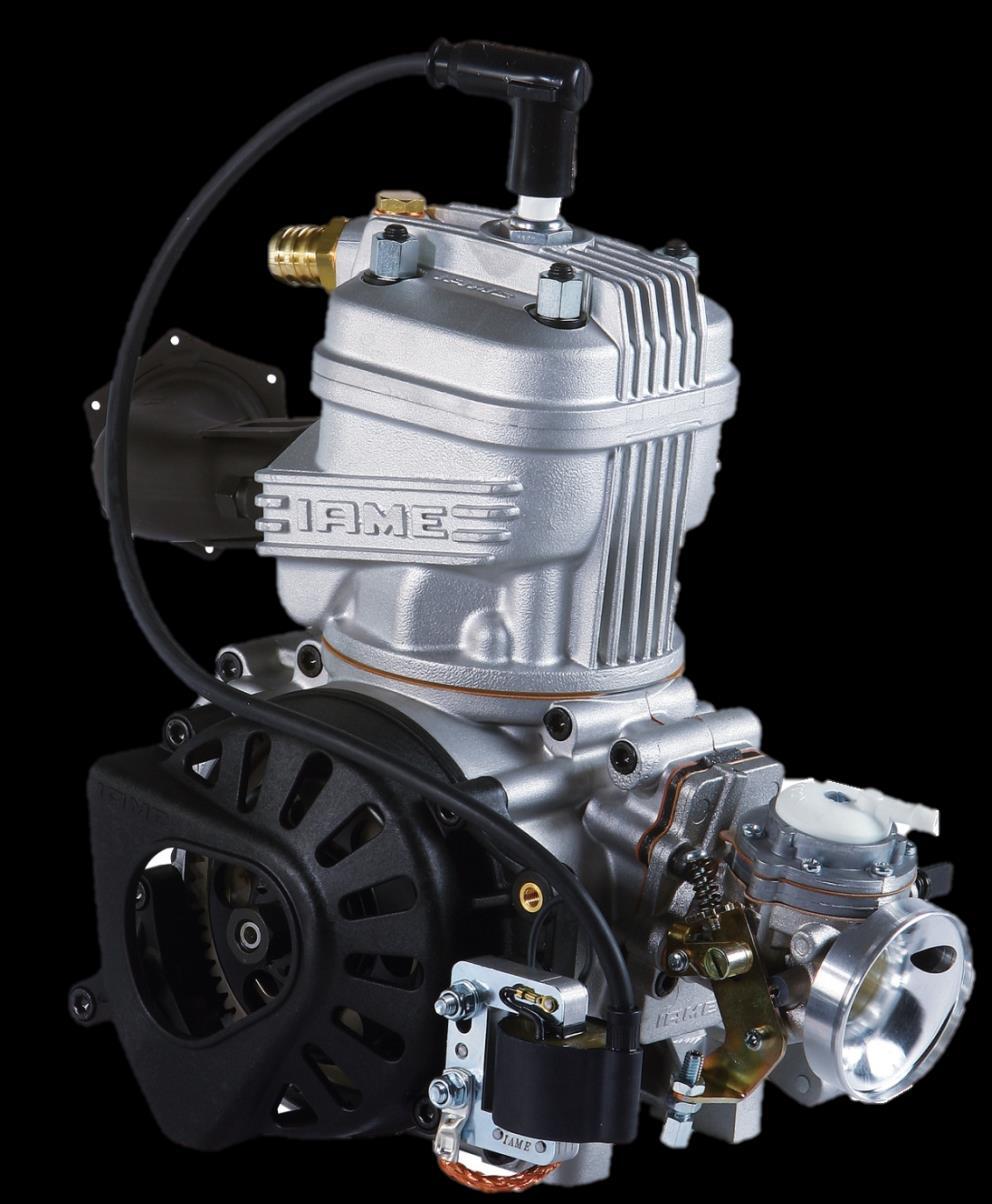
6 1.4 ACCESSORIES SPARK PLUG KIT EXHAUST SYSTEM BRUSHES KIT BATTERY SUPPORT KIT THERMOSTAT ELECTRIC PLANT CLUTCH COVER / H.T. COIL CARBURETTOR TRYTON HOBBY INLET SILENCER RADIATOR SUPPORT KIT WATER PUMP ASSEMBLY WATER HOSES KIT RADIATOR MAN-043E ENG
.")
7 1.5 ENGINE IDENTIFICATION NUMBER The official motor identification number can be found stamped on the lower left part of the crankcase, next to the electric starter (see fig.). The number normally includes a letter followed by 4 digits (there can be exceptions in some special cases). Other numbers stamped on the crankcase or other surfaces of the motor refer to various manufacturing processes and do not identify the motor. NOTE: In case of need for spares and when contacting the IAME Support Centers, please always refer to the Motor Identification Number and to the motor model MAN-043E ENG
8 Section 2 - PREPARATION AND INSTALLATION OF THE ENGINE ON THE CHASSIS NOTE: In case the engine is supplied already assembled on the chassis, it is at care of the assembler to follow these instructions. The final customer, in this case, can skip this section and can start reading from section 3. Whenever the engine or a component is disassembled, it is necessary to always follow the under shown Instructions for proper reassembly. 2.1 INSTALLATION SKETCH OF THE ENGINE ON THE CHASSIS CHASSIS RIGHT SIDE CHASSIS LEFT SIDE MAN-043E ENG
 ON THE PUMP BRACKET ON THE REAR CROSS RAIL (SEE FIG. 1).")
 AND PLACE THE CLAMPS ON THE REAR CROSS RAIL (N 2 SCREWS M6x25).")

9 2.2 INSTALL THE WATER COOLING SYSTEM NOTE: to install the water pump belts it is necessary to remove the rear axle. 1 2 REINSTALL THE REAR AXLE AFTER HAVING INSERTED TWO BELTS. SUGGESTION: INSTALL TWO EXTRA BELTS AS SPARES AND FIX THEM WITH TAPE TO THE AXLE. INSTALL THE WATER PUMP (1 SCREW M8x45 WITH WASHER AND NUT) ON THE PUMP BRACKET ON THE REAR CROSS RAIL (SEE FIG. 1). TORQUE AT Nm ( in-lb). Fig.1 IN CASE THERE IS NO BRACKET FOR THIS PURPOSE, IT IS NECESSARY TO INSTALL THE PUMP ON REMOVABLE CLAMPS AVAILABLE IN DIFFERENT DIAMETERS ( 28/30/32mm). ASSEMBLE THE PUMP FIXING BRACKET ON THE CLAMP (N 2 SCREWS M6x12) AND PLACE THE CLAMPS ON THE REAR CROSS RAIL (N 2 SCREWS M6x25). INSTALL THE PUMP ON THE BRACKET (N 1 SCREW M8x45 WITH WASHER AND NUT SEE FIG. 2). TIGHTEN BY HAND THE SCREW ON THE PUMP LETTING IT FREE TO ROTATE, FOR THE ALIGNMENT AND TENSIONING OF THE BELTS. SCREW M8X45 PUMP FIX. BRACKET SCREW M6X12 Fig.2 SCREW M6X25 3 INSTALL THE DRIVING PULLEY ON THE AXLE (2 CLAMPS AVAILABLE IN DIFFERENT DIAMETERS 30/35/40/50mm) ALIGNING ITS RACE WITH THE DRIVEN PULLEY ON THE PUMP (SEE FIG.3). FIX THE TWO CLAMPS WITH 2 SCREWS M5x22 (TIGHTEN AT 6 8 Nm) ( in-lb). TIGHTEN THE TWO SCREWS M6x25 ON THE PUMP FIXING CLAMPS AND THE SCREWS M6x12 ON THE PUMP FIXING BRACKET. SCREW M5X22 TIGHTEN AT 8 10 Nm (70 90 in-lb) Fig MAN-043E ENG
 Fig.")
. RUBBER DAMPENER Fig.")
.")
10 4 INSTALL THE BELTS AND TENSION (SEE FIG. 4). TIGHTEN THE SCREW M8x45. TORQUE AT Nm ( in-lb) Fig.4 BEFORE INSTALLING THE RADIATOR PREASSEMBLE THE FOLLOWING COMPONENTS 5 INSERT THE 4 RUBBER DAMPENERS INTO THE FIXING HOLES ON THE RADIATOR (SEE FIG. 5). RUBBER DAMPENER Fig.5 - PLACE THE RADIATOR SUPPORT BRACKET BETWEEN THE RADIATOR FIXINGS BY TILTING ONE END AND INSERTING IT THROUGH THE RUBBER DAMPENERS (SEE FIG. 6). NOTE: OIL THE BRACKET ENDS AND THE DAMPENERS HOLES. RADIATOR SUPPORT BRACKET Fig MAN-043E ENG

.")
 AND FIX IT TO THE TONGUE ON THE RADIATOR SUPPORT BRACKET (N 1 SCREW")
11 - COMPLETE INSERTION OF THE RADIATOR SUPPORT BRACKET IN THE RUBBER DAMPENERS (SEE FIG. 7 AND 8). Fig.7 Fig.8 7 FIX THE RADIATOR SUPPORT BRACKET INSERTING ALSO THE RADIATOR FIXING BRACKET (RADIATOR CAP SIDE N 1 SCREW M6x90 AND N 1 SCREW M6x85 WITH NUT). INSTALL THE L SHAPE BRACKET ON THE LOWER RADIATOR CLAMP (AVAILABLE IN DIFFERENT DIAMETERS 28/30/32mm - 2 SCREWS M6x12) AND FIX IT TO THE TONGUE ON THE RADIATOR SUPPORT BRACKET (N 1 SCREW M8x20 WITH NUT) SCREW M6X90 RADIATOR FIX. BRACKET. SCREW M8X20 SCREW M6X12 (SEE FIG. 9). SCREW M6X85 Fig.9 LOWER FIXING CLAMP MAN-043E ENG
 ONCE YOU FIND THE CORRECT POSITION TIGHTENS THE M6x25 SCREWS ON")

 Fig.")
12 8 PLACE THE RADIATOR FIXING CLAMP ON THE CHASSIS SIDE RAIL (BRAKE SIDE) (N 2 SCREWS M6x25). TIGHTEN THE BOLTS BY HAND (SEE FIG. 10). PLACE THE RADIATOR SO THAT THE HOLE ON THE RADIATOR BRACKET AND ONE OF THE UPPER HOLES ON THE BEARING SUPPORT BOX MATCH (N 1 SCREW M8) ONCE YOU FIND THE CORRECT POSITION TIGHTENS THE M6x25 SCREWS ON THE LOWER CLAMP FIXING THE RADIATOR. TIGHTEN AT 8 10 Nm (70 90 in-lb). Fig.10 9 THE KIT INCLUDES THREE RUBBER HOSES - CONNECT THE FIRST HOSE TO THE FITTING ON THE RADIATOR INLET AND THE FITTING ON THE ENGINE OUTLET, TIGHTEN WITH STEEL CLAMPS ON BOTH SIDES. - CONNECT THE SECOND HOSE TO THE FITTINGS ON THE RADIATOR OUTLET AND THE PUMP INLET, TIGHTEN WITH STEEL CLAMPS ON BOTH SIDES. - CONNECT THE THIRD HOSE TO THE FITTINGS ON THE PUMP OUTLET AND THE ENGINE INLET. TIGHTEN WITH STEEL CLAMPS ON BOTH SIDES. (SEE FIG. 11) Fig TO INSTALL THE THERMOSTAT REGULATING THE WATER TEMPERATURE, CUT THE HOSE CONNECTING THE FITTING ON THE RADIATOR INLET AND THE FITTING ON THE ENGINE OUTLET. INSTALL THE THERMOSTAT SO THAT THE ARROW IS TURNED TOWARDS THE RADIATOR (SEE FIG. 12) TIGHTEN WITH STEEL CLAMPS ON BOTH SIDES. Fig.12 BEFORE STARTING THE ENGINE, FOLLOW THESE RECOMMENDATIONS: Unscrew the cap on the radiator and loosen the breather plug on the engine head. Fill the radiator until the water comes out from the plug (there is no air in the system now) and the radiator is completely filled. Tighten the cap (the system contains appr. 1 lt. of water). It is advisable to put a small cup to recover water from the breather on the cap in case of boiling water. After the engine running-in, check the water level in the radiator and top up if necessary. In the event of a long inactivity of the engine, remove the hoses and empty the water circuit to avoid damages to the engine or parts due to cold temperature MAN-043E ENG
. Fig.1 2.3.")
 13mm SOCKET WRENCH OR (13 mm OPEN WRENCH) 2.4 PREPARATION AND INSTALLATON OF THE MOTOR-MOUNT NOTE: ALL THE DIMENSIONS ARE IN MILLIMETERS 2.4.1 DRILL 4 HOLES (DIAM.")
13 2.3 EXHAUST HEADER ASSEMBLY NOTE: THE ENGINE IS SUPPLIED WITH THE EXHAUST GASKET AND NUTS ALREADY INSERTED. WHEN THE SHIPMENT IS MADE THE INTERNAL PARTS OF THE ENGINE ARE PROTECTED BY A BLIND GASKET. (SEE FIG. 1). Fig REMOVE THE NUTS AND THE EXHAUST COVER MAKE SURE THE EXHAUST GASKET IS IN SEAT AND INSTALL THE EXHAUST HEADER (SEE FIG 2) INSTALL THE TWO WASHERS 8mm. Fig INSTALL THE TWO 2 NUTS M8. TORQUE AT Nm ( in-lb) 13mm SOCKET WRENCH OR (13 mm OPEN WRENCH) 2.4 PREPARATION AND INSTALLATON OF THE MOTOR-MOUNT NOTE: ALL THE DIMENSIONS ARE IN MILLIMETERS DRILL 4 HOLES (DIAM mm) IN THE MOTOR-MOUNT. MOTOR MOUNT HORIZONTAL VIEW MAN-043E ENG
. 6 mm ALLEN WRENCH (SEE FIG. 3 AND DRAW. PAG.")
. WARNING: MAKE SURE THAT THE PRESSURE HOLE ON THE GASKET IS NOT PLUGGED. Fig.4 2.5.2 INSTALL THE CARBURETOR.")
 5 mm ALLEN WARNING: WHEN REPLACING THE CARB GASKET ALWAYS MAKE SURE THAT THE GASKET IS INSTALLED SO THAT THE")
14 2.4.2 INSTALL THE MOTOR-MOUNT, MAKE SURE TO USE THE M8 ALLEN SCREWS, WITH A LENGHT SUCH AS TO ENGAGE, IN THE CRANKCASE, A THREADED LENGHT OF 16 19mm (THE SCREW MUST PROTRUDE FROM THE PLATE FOR 16 19mm ). 6 mm ALLEN WRENCH (SEE FIG. 3 AND DRAW. PAG. 11) 4 ALLEN SCREWS M8 TORQUE AT Nm ( in-lb) Fig INSTALL THE CARBURETOR REMOVE THE PLASTIC PLUG FROM THE INLET MANIFOLD (SEE FIG. 4). WARNING: MAKE SURE THAT THE PRESSURE HOLE ON THE GASKET IS NOT PLUGGED. Fig INSTALL THE CARBURETOR. TWO 2 NUTS M6 AND TWO WASHERS (SEE FIG. 5). TORQUE AT 6 10 Nm (50 90 in-lb) 5 mm ALLEN WARNING: WHEN REPLACING THE CARB GASKET ALWAYS MAKE SURE THAT THE GASKET IS INSTALLED SO THAT THE HOLE IN THE GASKET MATCHES WITH THE TWO PRESSURE HOLES IN THE CARB. AND IN THE CRANKCASE: OTHERWISE THE ENGINE WON T START. Fig MAN-043E ENG


 Fig.7 2.6.3 INSTALL THE CHAIN (PITCH: 7.")

15 2.6 INSTALL THE ENGINE ON THE CHASSIS POSITION THE ENGINE ON THE TWO OUTSIDE MAIN RAILS AND FIX THE MOTOR- MOUNT WITH TWO CLAMPS. (SEE FIG. 6) SUGGESTION: NEVER TORQUE COMPLETELY THE CLAMPS UNTIL THE CHAIN IS INSTALLED AND PROPERLY ALIGNED. Fig CHECK THE ALIGNMENT OF THE ENGINE SPROCKET AND THE AXLE SPROCKET WITH A STRAIGHT EDGE. (SEE FIG. 7) Fig INSTALL THE CHAIN (PITCH: 7.775) (SEE FIG. 8) Fig MOVE THE ENGINE ON THE RAILS AND OPTIMIZE THE CHAIN TENSION. WARNING: THE PLAY OF THE CHAIN MUST BE APPR. 15mm (½+¾), MEASURED IN THE SHOWN POINT (SEE FIG. 9). 15mm TORQUE THE CLAMP SCREWS Fig MAN-043E ENG
.")


16 2.7 INSTALL THE CLUTCH COVER WITH H.T. COIL REMOVE THE 3 SCREWS M6x25 ON THE CRANKCASE (SEE FIG.10) AND INSTALL THE CLUTCH COVER WITH H.T. COIL. (SEE FIG.11). 5 mm ALLEN Fig.10 TORQUE THE 3 SCREWS AT 8 10 Nm (70 90 in-lb). NOTE: IF A HORIZONTAL MOTOR-MOUNT IS USED CHECK AND SEE IF THERE IS SUFFICIENT SPACE BETWEEN THE CHAIN AND THE UPPER PART OF THE CLUTCH COVER. IF THIS IS LOWER THAN 6 7 mm WIDEN THE CHAIN OPENING WITH A FILE. TO CHECK THIS WE SUGGEST TO INSTALL THE SPROCKET WITH THE HIGHEST AVAILABLE TOOTH NUMBER Fig CONNECT THE COIL COPPER CABLE ON THE HOLE ON THE CRANKCASE (SCREW M6x12 5 mm ALLEN Fig.12 (SEE FIG. 12). TORQUE AT 8 10 Nm (70 90 in-lb) WARNING: ALWAYS MAKE SURE THAT THE GROUND CABLE ALWAYS CONNECTS THE COIL WITH THE ENGINE. AN INADEQUATE GROUNDING COULD DAMAGE THE IGNITION BEYOND REPAIR. THE POSITION OF THE H.T. COIL HAS BEEN CHOSEN TO BE AS FAR AS POSSIBLE FROM THE EXHAUST AS THE EXCESSIVE HEAT COULD DAMAGE THE COIL BEYOND REPAIR MAN-043E ENG
 NOTE: For a correct installation")
.")
. Fig.13 Fig.")


 WRENCH 4mm WARNING: THE CABLES HARNESS")

17 2.8 MOUNTING OF THE ELECTRIC PLANT AND CONNECTORS (complete scheme in the drawing at the end of the document) NOTE: For a correct installation follow the under shown instructions. MOUNT THE SILENT BLOCKS ON THE UPPER CLAMP (FIG. 13). COMPLETE THE MOUNTING OF THE CLAMPS ON THE BATTERY SUPPORT WITH THE N 4 SCREWS M6x25, N 2 SCREWS FOR EACH CLAMP (FIG. 14). Fig.13 Fig.14 TORQUE AT 6 8 Nm (50 70 in-lb) WRENCH 4mm NOTA: THE DIFFERENT HOLES ON THE SUPPORT ALLOW TO ADAPT THE THE SYSTEM TO ALL CHASSIS. PLACE THE SUPPORT PLATE ON THE SUPPORT AND FIX THROUGH THE N 3 SCREWS M5x10 AND CONCERNED WASHERS AND NUTS. TORQUE AT 6 8 Nm (50 70 in-lb) WRENCH 4mm Fig.15 PLACE THE ELECTRONIC BOX ON THE PLATE AND FIX IT THROUGH THE N.2 SCREWS M5x15 E AND CONCEARNED WASHERS AND SELF LOCKING NUTS. TORQUE AT 6 8 Nm (50 70 in-lb) WRENCH 4mm WARNING: THE CABLES HARNESS DOESN T HAVE TO GET IN CONTACT WITH THE SOIL OR WITH ROLLING PARTS TO AVOID IRREPARABLE DAMAGES. DRILL A HOLE (Ø6mm) IN THE FRONT PART OF THE RELAY BOX AS SHOWN IN THE PICTURE AND FIX THE RELAY THROUGH THE SCREW M5x20 WITH WASHER ON THE PLATE. (Fig.17) Fig.16 TORQUE AT 6 8 Nm (50 70 in-lb) WRENCH 4mm Fig MAN-043E ENG

 Fig.")
 Fig.")
 Fig.")
 Fig.")

18 PLACE THE PLASTIC CLAMPS IN THE DEDICATED HOLES AND PUT THE FUSE HOLDER IN POSITION AND THEN TIGHTEN THE PLASTIC CLAMPS TO FIX THE FUSE CASE. CUT OFF EXCEEDING PLASTIC CLAMPS. (Fig.18) Fig.18 MOUNT THE KEY BLOCK IN THE DEDICATED HOUSING. (Fig.19) Fig.19 SLIDE THE BATTERY FIXING STRIPE IN THE DEDICATED SLOTS. (Fig.20) Fig.20 PLACE THE BATTERY IN THE DEDICATED SLOT. (Fig.21) Fig.21 PLACE THE CABLES AT DESIRED CONVENIENCE, IN A PRACTICAL AND SAFE WAY AND TIGHTEN THE BATTERY STRIPE. ADVICE: CONNECT THE BATTERY ONLY BEFORE STARTING THE ENGINE. PROTECT THE CONNECTIONS ON THE BATTERY WITH ISOLATING TAPE TO AVOID ACCIDENTAL RELEASE OF THE FASTONS. Fig MAN-043E ENG
 CONNECT THE STARTER MOTOR PIN WITH ITS CORRESPONDING ON THE CABLES HARNESS.")


19 CONNECT THE STATOR PIN WITH THE PIN ON THE CABLES HARNESS. Fig.23 (FIG. 23) CONNECT THE STARTER MOTOR PIN WITH ITS CORRESPONDING ON THE CABLES HARNESS. (FIG. 24). WARNING: MAKE SURE THAT THE SECURITY FLAPS SNAP TO GUARANTEE THE CORRECT CONTACT OF THE TWO ENDS AND A SAFE TIGHTENING. Fig.24 VERIFY THE PRESENCE OF THE PLASTIC CLAMP ON THE STARTER MOTOR AND THAT IT FIXES THE CABLE ON THE BODY OF THE STARTER ENGINE. (FIG. 25). WARNING: THIS OPERATION IS VERY IMPORTANT AS THE VIBRATIONS COULD CAUSE DAMAGES TO THE INTERNAL STARTER MOTOR CONNECTIONS. Fig.25 PLACE THE GROUND CABLE BUTTONHOLE END (Ø 6.5mm) ON THE BACK OF THE ENGINE. (FIG. 26). Fig MAN-043E ENG


. TUBE KEY 10mm Fig.")

20 FIX THE BUTTONHOLE END OF THE GROUND CABLE THROUGH THE M6x12 SCREW PRESENT ON THE STARTER ENGINE. ALLEN WRENCH 5 mm Fig.27 (FIG. 27) TORQUE AT 8 10 Nm (70 90 in-lb) WARNING: THIS OPERATION IS FUNDAMENTAL AS AN IMPROPER GROUNDING COULD IRREPARABLY DAMAGE THE CELECTRONIC BOX. FIX THE BUTTONHOLE END OF THE SECOND GROUND CABLE TO THE H.T. COIL THROUGH THE M6 NUT OF THE H.T. COIL. (FIG. 28). TUBE KEY 10mm Fig.28 TORQUE AT 8 10 Nm (70 90 in-lb) WARNING: THIS OPERATION IS FUNDAMENTAL AS AN IMPROPER GROUNDING COULD IRREPARABLY DAMAGE THE CELECTRONIC BOX. CONNECT THE PIN OF THE CABLE OF DELIVRED BY THE H.T. COIL TO THE CABLE COMING FROM THE CABLES HARNESS. Fig.29 (FIG. 29) WARNING: USE A PLASTIC CLAMP TO FIX THE CABLE ON THE H.T. COIL TO AVOID THE ACCIDENTAL RELEASE OF THE PINS. (FIG. 30) Fig MAN-043E ENG
 CONNECT THE STARTER RELAY TO THE 4 POLES PIN ON THE CABLES HARNESS. (FIG. 32). Fig.")


 Fig.")

21 CONNECT THE ELECTRONIC BOX TO THE 20 POLES CONNECTOR OF THE CABLES HARNESS. ( FIG. 31) CONNECT THE STARTER RELAY TO THE 4 POLES PIN ON THE CABLES HARNESS. (FIG. 32). Fig.31 WARNING: MAKE SURE THAT THE SECURITY FLAPS SNAP TO GUARANTEE THE CORRECT CONTACT OF THE TWO ENDS AND A SAFE TIGHTENING. Fig.32 CONNECT THE PIN OF THE KEY BLOCK TO THE 8 POLES PIN FROM THE CABLES HARNESS Fig.33 (FIG. 33) WARNING: MAKE SURE THAT THE SECURITY FLAPS SNAP TO GUARANTEE THE CORRECT CONTACT OF THE TWO ENDS AND A SAFE TIGHTENING. SCREW THE SPARK PLUG CAP ON THE H.T. COIL CABLE. (FIG. 34) Fig.34 Fig.34 FIX THE SPARK PLUG CAP ON THE H.T. COIL CABLE WITH A PLASTIC CLAMP. (FIG. 35) Fig.35 MOUNT THE SPARK PLUG PROVIDED WITH THE ENGINE AND TORQUE A Nm ( in-lb) PLACE THE SPARK PLUG CAP ON THE SPARK PLUG. 2.9 INLET SILENCER MOUNTING Fig.36 MAKE SURE THAT THE INTAKE SILENCER IS POSITIONED WITH THE HOLES UPSIDE AND THAT THEY ARE NOT OBSTRUCTED. TIGHTEN THE CLAMP ON THE CARBURETTOR AND FIX THE INLET SILENCER WITH THE DEDICATED CLAMP ON THE CHASSIS TUBE. (FIG. 36) MAN-043E ENG


22 2.10 INSTALL THE EXHAUST NOTE: SEE SECTION 3.8 FOR THE RECOMMENDATIONS ON THE IDEAL EXHAUST LENGHT INSTALL THE FLEXIBLE (L= 65mm FLEXIBLE COMPLETELY CLOSED ) AND THE EXHAUST HEADER (SEE FIG. 37) AND FIT THE INSULATING SLEEVE ON THE FLEXIBLE (SEE FIG. 38) Fig.37 FLEXIBLE Fig.38 INSULATING SLEEVE INSERT THE FLEXIBLE ON THE EXHAUST HEADER AND FIX WITH THE 3 SPRINGS (SEE FIG. 39) Fig.39 THE ENGINE IS READY TO BE STARTED MAN-043E ENG

23 Section 3 - USE OF THE ENGINE 3.1 CHARGING OF THE OIL IN THE GEARBOX WARNING: The engine is suplied without oil in the gear box. Before starting the engine fill the box with SAE 30 oil, for example WLADOIL IAME OIL GEAR. Starting the engine with a dry box will damage the gears beyond repair - Charge of the gear box: Put the engine in horizontal position, unscrew the oil plug (n 1 on the picture), and oil level plug (n 2 on the picture), fill with oil until it comes out from the oil level plug (appr. 40cc of oil). Use a SAE 30 motor oil. 1 - Check the oil level Put the engine in horizontal position and unscrew the oil level plug. If the level is correct you should see a light outcome of oil, otherwise top up. - Discharge the oil Unscrew the oil level plug and loosen the charge plug. Tilt the engine to discharge the oil through the oil level plug GASOLINE AND OIL Use leaded or unleaded Premium gasoline 95 ROM, mixed with oil at 4,5% (22:1). Use oils containing castor oil which guarantees an optimized lubrication at high temperature. As on the other hand, use of castor oils creates gummy residues which give origin to carbon deposits, it is necessary to check and clean, at least every 5 10 hours, the piston and the head. Our experience dictates use of oils, such as: WLADOIL K 2T SHELL ADVANCE RACING M ELF HTX 909 ERG K KART FORMULA Once the fuel tank is filled, make sure that the gasoline reaches the carburetor before starting the engine. Never use the electric starter to suck the gasoline as this could discharge the battery. SUGGESTION: Disconnect the plastic tube on the carb. and the vent tube on the tank and pressurize the vent tube, until the gasoline comes out from the tube on the carb. Make sure that there is no air in the tube. Connect the tube on the carb. and on the vent MAN-043E ENG
 H (close the screw completely and then open): 1 T.O. (1 turn) Based on various factors as altitude, ambient temperature etc.")
 Adjust T.O. from closed to approximately 1 1/6 T.O. (1 turn and 10 ) (L) Adjust T.")

24 3.3 CARBURETTOR ADJUSTMENT GUIDE ( L ) LOW SPEED FUEL MIXTURE ( I ) THROTTLE SPEED SCREW ( H ) HIGH SPEED FUEL MIXTURE RICH 1 T.O. * LEAN 1 ¼ T.O. ¾ T.O. 1 ½ T.O. * T.O. = TURNS OPEN Normally the correct setting of the mixture screws, after engine run-in, is the following: L (close the screw completely and then open): 1 1/4 T.O. (1 turn and 15 ) H (close the screw completely and then open): 1 T.O. (1 turn) Based on various factors as altitude, ambient temperature etc. It might be necessary to reset the carburetor to optimize the performance of the engine. WARNING: Never lean too much as lean mixture will overheat engine and cause seizure Do not force H or L closed. It may damage the precision machined orifice and render the carb. inserviceable. The adjustment of screw must be performed with warm engine. (H) Adjust T.O. from closed to approximately 1 1/6 T.O. (1 turn and 10 ) (L) Adjust T.O. from closed to approximately 1 T.O. (1 turn) (I) Close by further 1 ½ T.O. after contact with throttle lever. Start the engine and warm it. If RPM too high adjust counterclockwise until clutch is disengaged. Turn c.c.w until. max. RPM is reached. Adjust further fractionally for rich idle. Trigger accelerator. If RPM decreases (L) Slowly adjust clockwise. If RPM increases Continue to turn clockwise until max. RPM is reached. Adjust c.c.w. fractionally for rich idle. Engine is now idling at max. attainable RPM, or slightly lower on rich side. Adjust I counterclockwise until RPM is reached. Recheck L screw for optimum setting required. Adjust H until best possible free speed is reached. Turn clockwise for higher RPM. Counterclockwise for lower RPM. Adjust L slightly richer by 1/8 ¼ T.O. Bad acceleration Return to idle and check acceleration for quick response and smooth pick-up. Good acceleration Engine is ready to operate MAN-043E ENG
25 3.4 STARTING AND STOPPING THE ENGINE Starting is achieved by the starting key. This is a 3 position key: 1- STOP (key can be removed) 2- KEY 3- RUN In STOP position the battery is disconnected and the engine stop signal is sent to the electronic box. In KEY position the battery is connected to the system and the stop signal is removed. In RUN position the battery is always connected and the electric starter, operation signal is sent to the electronic box. WARNING: The starting key assembly is supplied with two original keys. We recommend to separate the keys and to keep one in a protected place. In case of loss of both keys, it is necessary to replace the complete assembly. The starting procedure, from STOP position, is as follows: A) Turn the key to KEY position (this connect the battery). B) Turn the key to RUN position to start the engine (the electric starter is immediately disengaged when turning the key to KEY position, or when the electronic box detects an engine RPM higher than RPM). C) When the engine is running, the key can be left both in the RUN or KEY position. We suggest, for pratical reasons, to turn the key to KEY position; this allows with a single tripping to stop the engine (STOP position) or to restart it in case the engine is stopped (RUN position). Note: - in case the engine is stopped with the key in RUN position, to restart it, turn the key to STOP position and then again to KEY and RUN position to activate the electric starter. - With the key in KEY or RUN position and if the engine is stopped, to start the engine an external starter unit can also be used. In case the engine cannot be started within 5 seconds (check that gas gets to the carb.) interrupt and try again after 15 seconds. Short and frequent tries are better than long ones. To stop the engine turn the key to STOP position both from KEY (1 tripping) or from RUN (2 trippings) MAN-043E ENG
26 3.5 ENGINE RUNNING-IN The running-in of the engine must be performed following a few fundamental rules: 1. Adjust the carburetion. Start with an adjustment on the rich side. 2. Warm the engine gradually for about 5 minutes at half throttle, making some laps at low speed, gently closing and opening the carb. throttle (if a tachometer is installed never exceed RPM). Never keep the same RPM for a long time. 3. Increase the speed for 5 minutes at ¾ throttle opening. Never keep the same RPM for a long time. 4. Increase the speed for 5 minutes, at max. speed on the twisty parts of the circuit and making the engine rich at half straight (cover with the hand for an instant the holes on the inlet silencer keeping the throttle wide open). WARNING: Once the running-in is over and the engine is cold, check the torque of the exhaust header nuts as, during the running-in, the nuts tend to become loose (refer to the attached table). 3.6 RPM LIMITATION The electronic box incorporates an RPM limiter which prevents the engine from exceeding , or RPM, depending on the engine versions. This limit cannot be exceeded otherwise the engine could be damaged by the extremely high RPM. WARNING: Do not keep the engine for a long time at the RPM at which the limiter is functioning. This would cause malfunctions on the induction and damage the reed valve. When choosing the sprocket ratio always refer to a maximum limit which has to be equal to the engine version max rotation limit (i.e , or RPM), so that the incorporated limiter is not switched on continuously when the engine is running. 3.7 INLET SILENCER Make sure that the inlet holes on the filter are towards the upper side and that they are not plugged. Make sure that the clamp on the carburetor is not loosen and that the filter is well fastened to the chassis. Regularly clean the inside from oil deposits. If necessary remove the rubber manifold with filter and clean it with gasoline or solvent MAN-043E ENG
27 3.8 EXHAUST SYSTEM Before each test, make sure that the flexible is not damaged. Replace if necessary. WARNING: In case the flexible is damaged, metallic particles could be sucked in the engine and cause a seizure. Always make sure that the springs are well hooked and in place. In case of breakage, replace the broken spring. Never race the kart without the 3 springs in place, as otherwise the exhaust pipe could vibrate beyond control. Every hours, open the pipe end and make sure that the holes on the internal counter cone are not plugged. The best performance is achieved with a total exhaust lenght of: L = mm. Where L is measured from the flange on the exhaust header up to the first welding on the first cone of the exhaust muffler (see drawing). To achieve this dimension, the flexible (supplied with the engine) must be cut at a lenght of 65mm (flexible completely closed). Having fixed a sprocket ratio, it could be necessary to improve the engine performance either at low or at high RPM. This could be achieved by modifying the exhaust lenght. In general, by shortening the total exhaust lenght the low RPM an improvement at high RPM is achieved and vice versa, by lenghtening the exhaust lenght the low RPM is improved. When testing, never exceed in lenghtening or shortening the flexible by more than 5mm per time MAN-043E ENG
28 3.9 BATTERY The battery (12 V 9 Ah) is sealed and without maintenance (battery not included in the engine package). In order to lenghten the battery life it is recommended to follow few suggestions: When the tension drops below 12.6V. it is necessary to recharge the battery. Max. allowed recharging current is 1.8A. The ideal recharge is achieved with an average charging current of A. (recharging time of appr. 10 h.) and at an ambient temperature between 0 and 40 C. ATTENTION: An overcharge or an extremely quick charge with excessive current could damage the battery ( the battery would tend to swell). Choose a battery charger with the following characteristics: Feed tension: 90/250 Vac 50/60 Hz Outlet tension: 15 V full charge 13.8 stand-by Max. outlet current: 2A full charge During transportation or storage, the battery could loose its charge due to the self discharge (0.1% max per day). Fully recharge battery before use. WARNING: Always connect the - (negative) terminal before and the pole + (positive terminal after). Always disconnect the battery in opposite order. Recharge the battery at least once every 6 months. Never let the battery tension dropping under 8V, as whenever it drops under this limit, the battery cannot be used any longer and it has to be replaced. Never put the battery in contact with solvents, oils, plastifiers or rags containing such elements. The external case of the battery could be damaged. Never press or bend or overheat (by welding) the battery terminals. Other recommendations Pay attention not to have free fires upon or around the battery. Never short-circuit the terminals. Never open the battery or throw it in the fire. In case the electrolyte (diluted Sulfuric Acid) gets in contact with skin or clothes, wash immediately with water. In case it gets in touch with eyes, wash and apply for medical assistance. Carefully check the external case of battery and replace in case of breakages, swellings of the case or of battery cover. Before use, clean the battery from dust and check that the terminals are not oxydized or damaged. When the battery comes to an end never throw it in the garbage but deliver it to an authorized disposer MAN-043E ENG
29 3.10 WARNINGS ON THE ELECTRICAL SYSTEM We are here listing the main warnings on the electrical system. Please keep this in mind during the whole life of the engine. WARNING: If these prescriptions are not followed the electrical system and the engine could be damaged beyond repair. No obligation of IAME exists in this case. 1) Please turn the key to STOP position every time the engine is stopped. If the key is left in KEY position, for a long time, even if the engine is stopped, the battery would be discharged completely. 2) Never disconnect the ground cables with eyelets when the engine is in operation. 3) Disconnecting the battery when the engine is in operation DOES NOT increase the engine performance. Vice versa, the ignition advance could become very irregular at low RPM thus reducing the performance. 4) To fasten the eyelet terminal (groundings) of the wiring harness always use flat or open washers. Never use tab washers. 5) When disconnecting the connectors, always press the fixing tongues. Always pull the connectors to disconnect. NEVER PULL THE CABLES. 6) The electronic box and the starting relay must always be installed with their connector towards the bottom to avoid back water, dampness or dirt in the connector body. 7) Always correctly fix the H.T. coil with both screws, make sure that the laminations pack on H.T. coil is connected to the engine with the grounding cable. The eyelet connector must be directly in contact with the laminations pack on the H.T. coil. 8) Never use H.T. coils different than the original coil on the engine. Use of different coil may cause damages to the electronic box. 9) The digital assembly needs use of a resistive spark plug cap or spark plug. The resistor value must be equal or higher than 5 Kohm. Avoid use of resistive H.T. cables. 10) The electrical system is protected against battery polarity reversal. When reversing the connectors on the battery, the protection circuit activates the fuse as soon as the key is on KEY or RUN position. The fuse must then be replaced. 11) Replace the fuse after having disconnected both terminals on the battery. Only use 5A strip fuse. Use of fuses with higher amperage might damage the electronic box whenever the battery polarity is reversed. 12) Only use sealed lead type batteries as specified by IAME. Only use 12V. batteries. 13) Always disconnect the battery from the electrical system when recharging the battery with an external battery charger, otherwise the internal voltage regulator could be damaged. 14) DO NOT connect batteries in parallel; this might cause explosions and damages to the operator. The recharge of the battery, in normal conditions, is guaranteed by the electrical system. A few minutes of engine in operation are sufficient to recover the energy lost when starting the engine. 15) In case the battery must feed other users (Tachometer, Telemetry etc ), first contact IAME to check the recharge capacity of the system. 16) Modifications, interventions and additions to the original electric system might cause malfunctions. No obligation of IAME exists in this case MAN-043E ENG
30 3.11 SPARK PLUG AND THERMAL DEGREE The engine is supplied with a standard NGK BR10EG spark plug, which represents a good compromise between the needs of a good running-in and the racing needs in normal conditions. Use of different spark plugs is possible and, as a general information, we are attaching a correspondence list among spark plugs of other brands, based on thermal degree which represents the capacity of the spark plug to dissipate the internal heat. The colour of the various parts of the spark plug more exposed to the combustion flames gives a good indication on the adequacy of the thermal degree and on the carburetion. It is necessary though to understand which of the two parameters has to be changed and only the experience tells how to identify the most proper thermal degree of a spark plug as lean or rich mixtures can generate the same final look which can also be achieved with a hot or cold spark plug. See table: An excessive warm spark plug shows the symptoms, listed aside. WARNING: Always use a warmer than standard spark plug with cold or rainy climate. Extremely clear colour, porous look and calcification of the electrodes and of the internal insulation. Irregularities in the ignition, preignition and detonation with tendency to perforate the top of the piston. Note: some of these symptoms can be achieved with lean mixtures. A correct thermal degree shows: Colour of the insulator end from yellow grey to dark brown for mixtures respectively lean or rich. An excessively cold spark plug shows the symptoms, listed aside. WARNING: Always use a colder than standard spark plug with hot climates. Insulator end and electrodes covered with black shady soot. Ignition difficulties Note: a wet or oily electrode could also mean an excessively rich mixture. COMPARISON TABLE BASED ON THE THERMAL DEGREE HOT BOSCH NGK CHAMPION WO8CS BR9EG N54R WO7CS BR10EG N52R WO6CS BR11EG COLD MAN-043E ENG
31 3.12 CHOICE OF THE BEST SPROCKET RATIO The life of an engine depends on many factors but most of all, upon the speed at which the engine is operated. If an engine is normally operated at speed higher than what recommended by the manufacturer, the wears and stress of the various components (con-rods, roller cages, bearings etc.) will be such as to drastically reduce the life of the engine itself. It is therefore extremely important that the user respects operating limits imposed by the manufacturer. The operating limit for the IAME X30 engine are respectively: Rpm Rpm Rpm According to the different engine versions. WARNING: Never exceed the above limit. No obligation of IAME exists in case the above limit is exceeded. In case the user wishes to optimize on the track the sprocket ratio in order to achieve the best possible performance, without abusing the engine, follow the under shown recommendations. The engines are supplied with a 11 teeth sproket (pitch mm.), but 10 and 12 teeth sprockets are available as accessories. Table 1 shows the various ratios between the sprocket on the axle and the engine sprocket given the different axle sprocket. Tab.1 Sprocket ratio Teeth n - Engine sprocket Sprocket ratio Teeth n - Engine sprocket Teeth n Axle sprocket Teeth n Axle sprocket ,20 6, ,30 7,55 6, ,30 6,64 6, ,40 7, ,40 6,73 6, ,50 7,73 7, ,50 6,82 6, ,60 7,82 7, ,60 6,91 6, ,70 7,91 7, ,70 7,00 6, ,80 8,00 7, ,80 7,09 6,5 89 8,90 8,09 7, ,90 7,18 6, ,00 8,18 7,5 80 8,00 7,27 6, ,10 8,27 7, ,10 7,36 6, ,20 8,36 7, ,20 7,45 6,83 For the operation limit max. of , , RPM the following table (Tab. 2a / 2b / 2c) has been prepared. SUGGESTION: During the track tests we recommend use of a tachometer recording the max. obtained engine RPM. Use spark plug caps with a resistance of 5KΩ to avoid the eventual interferences between the engine ignition and the tachometer and/or telemetry MAN-043E ENG

32 The following example should clarify the procedure for the optimization of the sprocket ratio. Assume to use the engine with Z=10 teeth engine sprocket and that during the preliminary track tests a Z= 77 teeth axle sprocket has been used. From Table 1 with Z=10 as engine sprocket and Z= 77 on the axle sprocket, a ratio of 7.70 is found. Make a few laps on the track and record the maximum engine rpm achieved. Let us assume that you detect RPM. From the Table 2a, to achieve a max RPM of RPM (operating limit for the 1 st engine X30 version) a sprocket ratio between 7.83 and 8.05 should be used (having used during the tests, a sprocket ratio of 7.7 and having achieved RPM). From Table 1, with these values, a sprocket ratio of 10:78 / 10:80 should be used or, having a Z=11 on the engine sprocket, a ratio 11:87 should be used MAN-043E ENG

33 MAN-043E ENG
34 4.1 CENTRIFUGAL CLUTCH Section 4 - BASIC MAINTENANCE The engine has a low maintenance dry centrifugal clutch. The following prescriptions, if carefully followed, will allow a clutch longlife. When starting the engine, make sure that the brake pedal is fully pressed to avoid sudden accelerations. WARNING: Once the engine is started, avoid useless accelerations which can overheat and deteriorate the clutch. Oil the chain before each session. Immediately after each race or test, check the engine sprocket. Replace if necessary. A bad alignment of the engine sprocket with the axle sprocket or the lack of oil will damage irreparably the sprocket. Check the clutch: every 5 hours of use. When metallic noises are heard inside the clutch. If the kart dragging speed exceeds 6000 RPM. Every time the clutch has overheated (presence of smoke or smell of burning). To check the clutch, you must remove the clutch cover and the clutch drum. Replace the clutch: whenever the thickness of the friction material (see drawing) is lower than 1.5mm on point A of the clutch or if the body diameter is lower than 83mm. Whenever the external friction material in the A portion of the clutch is very rough (wear or degradation of the friction material due to overheating). WARNING: In case the friction material has been totally worn out and there has been a metal contact between the clutch body and the clutch drum, it is necessary to replace the clutch drum. See drawing MAN-043E ENG
35 4.2 INSTRUCTIONS FOR THE DISASSEMBLY/ASSEMBLY OF THE CLUTCH WARNING: the following operations can be performed by a skilled mechanic, under the conditions to have available the dedicated tools shown in the text, otherwise it is necessary to apply to an Authorized Service Center. Refer to the following drawing during the operations. 1 Drum nut 5 Screw 9 Clutch body 2 External washer 6 Clutch drum 10 Starter ring 3 Roller cage 7 Internal washer 11 Screw 4 Sprocket 8 Locking nut OPERATIONS TOOLS Clutch disassembly 1. Remove the clutch cover (3 screws M6). Allen wrench 5mm T type 2. Remove the Bendix support and replace it with starter wheel locking tool. Starter wheel locking tool: P.N. S Remove nut (1 nut M10). 12 point wrench 17 mm 4. Remove the external washer, the drum complete with roller cage, the internal washer. 5. Remove the special tool from the head and using the clutch wrench remove the M20x1 nut and the starter wheel. Starter wheel locking tool: P.N. S884 30mm socket. WARNING: turn clockwise as the nut has left thread 6. Apply the clutch puller on clutch hub and remove the clutch hub with the starter wheel. Clutch puller: P.N. ATT point wrench 12mm. 7. Remove the starter wheel (3 screws M6) Allen wrench 5mm T type MAN-043E ENG
36 Before assembling the clutch, wash with diluent the shaft taper, the connecting hole on the clutch body, the clutch drum and the starter wheel. Install clutch 1. Install the starter wheel on the clutch hub by matching the three holes and the dragging pin (3 screws M6). ATTENTION: make sure to always install the Ø 7 mm dragging pin as otherwise, the eventual kick backs, could break the screws. Allen wrench 5mm T type (torque at 8 10 Nm) (70 90 in-lb) (apply Loctite on the threads) 2. Install clutch body and the cone safety washer. Apply Loctite 641 for coaxial lockings 3. Install the clutch body fixing nut and starter wheel, using the 30mm clutch wrench. ATTENTION: turn counterclockwise as nut has left thread. 4. Install the internal washer. ATTENTION: install washer with bevel towards internal part of the engine. Clean the roller cage and grease it before installing it on the crankshaft. 5. Install the clutch drum and the external washer. Starter wheel locking tool: S point wrench 30 mm. (torque at Nm) ( in-lb) ATTENTION: install washer with bevel towards internal part of the engine. 1. Install the starter wheel locking tool to prevent the shaft from turning and install the clutch cover (M10 nut). 2. Install the clutch cover (3 screws M6). Starter wheel locking tool: S mm socket (torque at Nm) ( in-lb) Allen wrench 5 mm T type. (torque at 8 10 Nm) (70 90 in-lb) 4.3 GEAR TIMING SCHEMATIC In case of assembly of the gears which drive the balance shaft, assembly must be performed following the timing schematic shown below. ATTENTION: An uncorrect assembly of the gears can cause a malfunction in the vibration reduction system MAN-043E ENG
.")
. Fig.")

37 4.4 REPLACEMENT OF THE STARTER BRUSHES OPERATIONS PICTURES 1. DISASSEMBLE THE STARTER - UNSCREW N 2 SCREWS M6x35 (see Fig.1). (5mm ALLEN WRENCH T TYPE) Fig.1 Fig.2 - REMOVE STARTER (see Fig.2). Fig.2 NOTE: ON THE ENGINES MANUFACTURED AFTER SEPTEMBER 05, THE STARTER CAN BE REMOVED WITHOUT TAKING AWAY THE GEARS COVER BUT SIMPLY BY REMOVING THE COVER CLAMP (see drawing) MAN-043E ENG
38 2. OPENING THE STARTER -REMOVE THE PLASTIC CLAMP AND UNSCREW THE SCREW M4 FIXING THE INPUT CABLE TO THE STARTER Fig.3 Fig.1 (see Fig.3) (PHILLIPS SCREWDRIVER) Fig.4 - UNSCREW 3 SCREWS M5 C (see Fig.4) (PHILLIPS SCREWDRIVER) MAN-043E ENG
 Fig.4 Fig.5 - REMOVE ROTOR FROM STARTER HEAD Fig.6 (see Fig.6) ATTENTION: WHEN EXTRACTING ROTOR, THE BRUSHES MAY SPRING OUT FROM THEIR SEATS.")
.")
39 - REMOVE DRUM FROM STARTER KEEPING ROTOR IN ITS SEAT (BE SURE TO HOLD THE ROTOR ON ITS TOOTHED SIDE TO PREVENT BRUSHES FROM FALLING OUT FROM THEIR SEAT) (see Fig.5) Fig.4 Fig.5 - REMOVE ROTOR FROM STARTER HEAD Fig.6 (see Fig.6) ATTENTION: WHEN EXTRACTING ROTOR, THE BRUSHES MAY SPRING OUT FROM THEIR SEATS. 3. REPLACING THE BRUSH A Fig.7 - UNSCREW THE 2 SCREWS M4 D RETAINING THE PLATE E (see Fig.7). (PHILLIPS SCREWDRIVER) Fig.8 - REMOVE THE LITTLE RUBBER CAP F (see Fig.8). (PLIERS) OUR SUGGESTION: SLIGHTLY OIL THE TIN PLATE TERMINAL END, TO MAKE EASIER THE EXTRACTION OF THE LITTLE RUBBER CAP MAN-043E ENG

. Fig.10 - INSTALL NEW BRUSH TERMINAL INSIDE (see Fig.")

40 - REMOVE SILICONE FROM BRUSHES WITH A SCREWDRIVER (see Fig.9). - REMOVE SPRINGS Fig.9 - MAKING PRESSURE EXTERNALLY ON THE TIN PLATE TERMINAL, REMOVE BRUSH. Fig.9 (see Fig.10). Fig.10 - INSTALL NEW BRUSH TERMINAL INSIDE (see Fig.11). - PLACE LITTLE RUBBER CAP ON THE TERMINAL Fig.11 - REINSTALL THE PLATE AND FIXE IT WITH THE 2 SCREWS M4 (see Fig.12). (PHILLIPS SCREWDRIVER) Fig MAN-043E ENG
 - EXTRACT THE BRUSH - FIX THE NEW BRUSH WITH SCREW M3 (PHILLIPS SCREWDRIVER) 5.")

. Fig.")

41 4. REPLACEMENT OF THE BRUSH B Fig.13 - UNLOOSE THE SCREW M3 G (see Fig.13) - EXTRACT THE BRUSH - FIX THE NEW BRUSH WITH SCREW M3 (PHILLIPS SCREWDRIVER) 5. CLOSING THE STARTER - INSERT THE NEW BRUSH SPRING "A" INTO ITS SEAT. - INSTALL THE BRUSH. - KEEP THE BRUSH IN PLACE BY PRESSING TOWARDS THE OUTER AND CLAMP IT WITH AN IRON WIRE BENT AS A HOOK. REPEAT THE SAME PROCEDURE TO INSTALL THE BRUSH B (see Fig.14). Fig.14 - INSTALL THE STARTER ROTOR BETWEEN THE BRUSHES AND CHECK, THAT THEY ARE ALWAYS IN CONTACT WITH THE CYLINDRIC COPPER PART OF THE ROTOR, EVEN WHEN THEY ARE RELEASED (see Fig.15). Fig.15 OUR SUGGESTION: TO IMPROVE THE BRUSHES LIFE, SECURE THE LITTLE WIRES WITH SILICONE (see Fig.16). Fig MAN-043E ENG
. Fig.17 - SCREW THE 3 SCREWS M5 (see Fig.18).")
42 - CHECK THAT O-RING "H" IS INSTALLED ON THE STARTER HEAD. - INSERT STARTER DRUM ON THE HEAD BEING CAREFUL TO PREVENT ROTOR FROM ROTATING AND TO PREVENT THE BRUSHES FROM FALLING OUT OF THEIR SEAT (see Fig. 17). Fig.17 - SCREW THE 3 SCREWS M5 (see Fig.18). (PHILLIPS SCREWDRIVER) - CHECK THAT THE STARTER ROTOR ROTATES FREELY. Fig.18 Fig.19 - CONNECT THE INPUT WIRING TO THE STARTER WITH THE SCREW M4 (see Fig.19). (PHILLIPS SCREWDRIVER) - SECURE THE WIRE TO THE STARTER BY MEANS OF A PLASTIC CLAMP (see Fig.20). 6. ASSEMBLING THE STARTER - PLACE THE STARTER INTO THE CRANKCASE (see Fig.20). OIL O-RING TO MAKE EASIER INSTALLATION. Fig.20 N 2 SCREWS TCH M6x35 TIGHTEN AT A 8 10 Nm ( in-lb ) (5mm WRENCH T TYPE) MAN-043E ENG
43 4.5 - TROBLESHOOTING Below are some common faults, their probable causes and suggested remedy. FAULTS PROBABLE CAUSES REMEDY Starter will not crank when turning the key to RUN position. Bad connections on starter cables Check and tighten Bad grounding Check connections and tighten Interruption on fuse Replace 5A strip fuse, after checking for eventual reversal of battery polarity. Damaged cables Replace Battery connection loose Check and tighten Battery discharged Recharge or replace battery Starter failure Overhaul starter Electronic box or relay failure Apply to Authorized Service Centers Starter cranks but engine won t start Bad cable connections Check connectors when turning the key in RUN Bad H.T. coil connections or coil Check / replace position. failure. Bad H.T. coil grounding. Check grounding Electronic box or ignition failure. Apply to Authorized Service Centers Wet spark plug. Replace Malfunction on induction system. Check status and connection on fuel pipe Replace gaskets and membranes on carburettor. Check reed petals. Replace if necessary. Engine starts but it stops after a few Bad cable connections Check stator connector seconds when turning the key in RUN position Electronic box or starter failure Apply to Authorized Service Centers Bad carburettor adjustment Check carburetor adjustment (see ( screw L) sect. 3.3) Insufficient fuel flow Check fuel flow lines and inlet filter The starter cranks also after the Electronic box failure Apply to Authorized Service engine is running. Centers Rough idle Bad carb. adjustement ( screw I) Check carburettor adjustment (see sect. 3.3) Drop in engine performance Bad compression Check piston Bad carburetor adjustment Check carburettor adjustment (see sect. 3.3) Insufficient fuel flow Check fuel flow lines and inlet filter Dirty inlet silencer Check and clean Burning smell, smoke Clutch overheating Check clutch (see sect. 4.1) Clutch engages at too high RPM Excessive wear of friction material Check clutch (see sect. 4.1) Oil or grease into the clutch drum Cleaning / Replace clutch hub Exhaust too noisy Damaged flexible Check and replace if necessary Springs damaged or lost Damaged insulating sleeve Damaged exhaust header MAN-043E ENG

44 4.6 - ENGINE PRESERVATION When engine is to remain unoperative for a long period it must be preserved as follow: Disconnect the battery and charge it periodically; Disconnect carburetor and clean it; Seal with tape the engine inlet and exhaust. The external of the engine must be cleaned. Spray with protective oil, the steel parts subject to oxidation. Keep the engine in a dry ambient. In the event of a long unoperative period of the engine, release the hose fixed between the water pump inlet and the radiator outlet (as shown in the picture) and empty the water circuit to avoid damages to the engine and the accessories due to freezing MAN-043E ENG

45 4.7 SCHEDULED MAINTENANCE The properly and timely execution of inspections and the respect of the program of checks, are the best warranties for safe utilization and durable engine. SCHEDULE COMPONENTS ACTIONS AND COMMENTS Before every using Exhaust flexible Check status Exhaust spring Check status Insulating sleeve Check status Exhaust Silencer Check status and the fixings Check wear Engine sprocket Check alignment with axle sprocket Engine chain Check wear, tensioning and lubrication s chain Battery Check status and the charge Cables and connectors Check status and restore the connections Grounding of engine, HT Coil Check status and restore the and electronic box connections Engine mounts and clamps Check torques Battery support and clamps Check torques After use Battery Disconnect Chain Lubrication chain Engine External cleaning Every 5 10 hours Bendix assembly Remove cover, clean internally Every: 20 hours non competitive use / 15 hours racing use Every: 20 hours non competitive use / 15 hours racing use Every: 40 hours non competitive use / 30 hours racing use Exhaust muffler Inlet silencer Engine head Clutch Full Piston parts (piston pin + segment + circlip) + Small end cage Crankcase Ball Bearing + Oil Seals + Big End cage + Silver Bronze Washer + Crankpin Crankcase + Conrod + Countershaft Remove muffler end, clean Open and clean Open and clean Open, check status of parts and if necessary replace part. Replace worn parts Replace worn parts Replace worn parts MAN-043E ENG
46 4.8 - WEAR STATUS EVALUATION TABLE - BEARINGS AND HALFCRANKSHAFT NOTE: ALWAYS CHECK DIMENSIONS IN DIFFERENT POINTS ON CIRCUMFERENCE, LOOKING FOR EVENTUAL OVALIZATIONS. On the following Table are shown the ovalization limits above which replacement is required. MEASURED PART (MEASURING INSTRUMENT) CRANKSHAFT BEARING SEAT (MICROMETER /100) LIMITS MIN. Ø29.96 BALANCE SHAFT EXTERNAL BEARING SEAT (MICROMETER /100) MIN. Ø24.96 BALANCE SHAFT INTERNAL BEARING SEAT (MICROMETER /100) MIN. Ø14.95 CRANKSHAFT BEARINGS (1/100 BORE GAUGE WITH CHECK RING Ø30) * MAX. Ø30.03 BALANCE SHAFT - EXTERNAL BEARING (1/100 BORE GAUGE WITH CHECK RING Ø25) * MAX. Ø25.03 BALANCE SHAFT INTERNAL BEARING (BORE GAUGE 1/100 WITH CHECK RING Ø15) * MAX. Ø15.03 * ATTENTION: THE MEASURED VALUE ON THE BEARING MUST ALWAYS BE COMPARED WITH THE SEAT VALUE (ON SHAFT AND/OR BALANCE SHAFT), TO CHECK THAT PLAY, BETWEEN SHAFT AND BEARING DOES NOT EXCEED THE LIMIT VALUE OF 0.05mm MAN-043E ENG

47 4.9 MAIN PRESCRIPTIONS CRANKSHAFT MATCHING THE PISTON Diametro sede cuscinetto su un motore nuovo Refer to the attached table to determine wear status of the crankshaft halves. Replace the part when the flow rate of the bearing is smaller than the original 0.03mm. ATTENTION: The replacement must be done every 40 hours for a use NOT competitive and every 30h for racing use. MAX ALLOWED OVALIZATION OF CON-ROD BIG-END ATTENTION: Play between piston and the liner must be mm. If the play is higher than 0.14mm replace the piston. The replacement of the piston must be done every 20 hours for a use NOT competitive and every 15h for racing use. The piston are measured at 17.5mm from bottom. Size of liner to be matched with piston is marked on top of piston with a green or red dot or with letter V (green) or R (red). If the size on piston top is marked with: - a green dot or letter V; add 0,01mm to size marked on the piston to match the liner size. Max. allowed ovalization between A and B on new conrod: 0.002mm. -a red dot or letter R; add 0,02 mm to size marked on the piston to match the liner size. Max. allowed ovalization between A and B on used conrod: 0.01mm. The replacement must be done every 40 hours for a use NOT competitive and every 30h for racing use, or in any case if the ovalizatino exceeds 0.01 mm (the difference between the measured diameter in the positions shown below "A" and "B"). AVERAGE LIFE OTHER COMPONENTS DESCRIPTION Big end cage + Crankpin + Silver Bronze Washer Small end cage + piston pin NO COMPETITIVE USE RACING USE 20 hours 15 hours 20 hours 15 hours Crankcase Ball Bearing + Oil Seals 20 hours 15 hours MAN-043E ENG

48 5.0 - MATCHING PLAYS CONROD LOWER AND UPPER END MAN-043E ENG
49 5.1 - TORQUE VALUES NOMINAL SIZE Q.TY FASTENER NAME WRENCH VALUES (Nm) VALUES (in*lb) M14x1,25 1 Spark plug Hex.20, M8x1,25 4 Head and cylinder nut Hex M8x1,25 2 Exhaust Header nut Hex M6x1 4 Reed group screw Allen M6x1 2 Carburettor fixing stud-bolt Allen M5x0,8 4 Grounding Coil fixing screw Allen M5x0,8 4 Ignition Dig. K stator fixing screw Allen M10x1 1 Ignition Dig. K rotor fixing nut Hex M6x1 3 "Bendix" support screw Allen M6x1 2 Starter fixing screws Allen M6x1 3 Clutch cover fixing screws Allen M10x1 1 Clutch holding Nut Hex M20x1 1 Starter ring fixing nut Hex M5x0,8 4 Engine sprocket fixing screw Allen M6x1 3 Clutch Hub / Starter ring fixing screw Allen M6x1 10 Crankcase fixing screw Allen M6x1 7 Gear cover fixing screw Allen M5x0,8 1 Balance shaft bearing fixing screw Allen M6x1 2 Coil fixing nut Hex M6x1 2 Coil / Starter ground fixing screw Allen M10x1 2 Oil charge / Discharge plug Hex MAN-043E ENG
50 5.2 - CROSS PATTERN LOCKING ORDER ON CRANKCASE MAN-043E ENG
51 5.3 - OVERHAUL TOOL LIST SPECIFIC TOOLS AVAILABLE AT IAME DESCRIPTION P.N. PISTON FITTING CLUTCH LOCKING WRENCH CLUTCH DISASSEMBLY TOOL C PISTON PIN FITTING PISTON CIRCLIP ASSEMBLY TOOL CRANKSHAFT ASSEMBLY KIT It includes: 10110B-C 10150A - crankpin bush CRANKSHAFT DISASSEMBLY KIT It includes: - crankshaft plate - crankshaft support - crankpin pusher - crankshaft insert BEARING DISASSEMBLY TOOL EXTERNAL BALANCE SHAFT BEARING ASSY/DISASSY TOOL BEARING ASSEMBLY TOOL INTERNAL BALANCE SHAFT BEARING ASSY/DISASSY TOOL OIL SEAL ASSEMBLY TOOL (without crankshaft) OIL SEAL ASSEMBLY TOOL (with installed crankshaft) GEAR COVER OIL SEAL ASSEMBLY TOOL 10100A-C A A ENGINE FIXING TOOL ON BENCH VICE (see attached drawing) STANDARD TOOLS ALLEN WRENCH- T TYPE 4mm ALLEN WRENCH- T TYPE 5mm ALLEN WRENCH 12mm HEXAGON RING WRENCH T TYPE 13mm 12 POINT WRENCH 10mm 12 POINT WRENCH 13mm 12 POINT WRENCH 14mm 12 POINT WRENCH 17mm 12 POINT WRENCH 19mm HEXAGON RING WRENCH 27mm HEXAGON RING WRENCH 30mm SPARKPLUG WRENCH 20.8mm SCREWDRIVER WITH ROUNDED EDGES PLASTIC MALLET COPPER MALLET TORQUE METER 10/13/30mm PLIERS FOR RETAINING RINGS 5 MeT PRESS MAN-043E ENG
52 5.4 FIXING TOOL ON VICE BENCH MAN-043E ENG


53 5.5 BEARING/OIL SEAL ASSEMBLY TOOL - DISEGNO S725/ MAN-043E ENG
125cc LEOPARD TaG engine 2003
 125cc LEOPARD TaG engine 2003 ASSEMBLY INSTRUCTIONS and USER MANUAL 18/10/02 mod. C MAN-016 D INDEX GENERAL DESCRIPTION OF THE "LEOPARD" ENGINE CHARACTERISTICS OF THE "LEOPARD" ENGINE OPERATIONAL LIMITS
X30 125cc Spec. EU ASSEMBLY INSTRUCTIONS AND USER MANUAL MAN-089
 X30 125cc Spec. EU ASSEMBLY INSTRUCTIONS AND USER MANUAL MAN-089 FEEDING Fuel mixture 98 RON and oil 5% (20:1) minimum. Engine oil CIK homologated. Our experience dictates use of oils, such as: - WLADOIL
BASIC MANUAL X30 125CC MAN-80
 BASIC MANUAL X30 125CC FEEDING Fuel mixture 98 RON and oil 5% (20:1) minimum. Engine oil CIK homologated. Our experience dictates use of oils, such as: - WLADOIL K 2T; - ELF HTX 909; - ELF HTX 976; - LEXOIL
ASSEMBLY INSTRUCTIONS
 C 125cc LEOPARD TaG engine 2003 ASSEMBLY INSTRUCTIONS and USER MANUAL 18/10/02 mod. INDEX GENERAL DESCRIPTION OF THE "LEOPARD" ENGINE CHARACTERISTICS OF THE "LEOPARD" ENGINE OPERATIONAL LIMITS 1- Contents
INSTALLATION MANUAL. REEDJET 100cc -TaG MAN-72/C - USA
 INSTALLATION MANUAL REEDJET 100cc -TaG MAN-72/C - USA I N D E X PAGE General description of engine 01 Engine features / Operational limits 02 Contents of packaging 02 Accessories 03 Engine identification
REEDJET AUS 100cc TaG
 REEDJET AUS 100cc TaG INSTALLATION MANUAL 01/11/04 MAN-033 GENERAL DESCRIPTION OF ENGINE This engine of the "TaG" series (Touch and Go) has been expressly designed and developed to power Karts for hobby
REEDSTER 125cc. F1 - F2 - F3 - F4 Versions ASSEMBLY INSTRUCTIONS & USER MANUAL
 REEDSTER 125cc F1 - F2 - F3 - F4 Versions ASSEMBLY INSTRUCTIONS & USER MANUAL 21/01/09 2 INDEX N Page Section 1 DESCRIPTION OF THE Parilla REEDSTER 125cc ENGINE 1 2 3 4 5 1.1. Main features 1.2. Engine
OVERHAUL MANUAL 28/09/05 mod. A 1 MAN-044 ING
 OVERHAUL MANUAL 28/09/05 mod. A 1 INDEX Page 1. - PARILLA X30 125cc RL TaG ENGINE DISASSEMBY 1 2. - CRANKSHAFT DISASSEMBLY/ ASSEMBLY 10 2.1- CRANKSHAFT DISASSEMBLY 10 2.2- CRANKSHAFT ASSEMBLY 12 3. - PARILLA
REEDSTER 125cc. versions: F1 - F2 - F3 - F4 OVERHAULING MANUAL
 REEDSTER 125cc versions: F1 - F2 - F3 - F4 OVERHAULING MANUAL 07/11/07 21/01/2009 1 INDEX Page 1. - REEDSTER 125cc ENGINE DISASSEMBLY 1 2. - CRANKSHAFT DISASSEMBLY / ASSEMBLY 13 2.1 - CRANKSHAFT DISASSEMBLY
MANUAL INDEX. Page 1. LEOPARD 125cc ENGINE DISASSEMBLY CRANKSHAFT DISASSEMBLY/ ASSEMBLY CRANKSHAFT DISASSEMBLY 8
 MANUAL INDEX Page 1. LEOPARD 125cc ENGINE DISASSEMBLY 1 2. - CRANKSHAFT DISASSEMBLY/ ASSEMBLY 8 2.1- CRANKSHAFT DISASSEMBLY 8 2.2- CRANKSHAFT ASSEMBLY 10 3. LEOPARD 125cc ASSEMBLY 13 4. - CHECK CYLINDER
BASIC MANUAL X30 SUPER 175CC MAN-78
 BASIC MANUAL X30 SUPER 175CC FEEDING Fuel mixture 98 RON and 4,5% oil (22:1 - CIK homologated) Our experience dictates use of oils, such as: - WLADOIL K 2T; - ELF HTX 909; - ELF HTX 976; - SHELL ADVANCE
BASIC INSTRUCTIONS SHIFTER KZ1 / KZ2 e X30 SHIFTER-TaG
 BASIC INSTRUCTIONS SHIFTER KZ1 / KZ2 e X30 SHIFTER-TaG FEEDING: by fuel mixture 98NO (min. 95NO) and 4% oil (CIK homologated). ATTENTION: the engine is supplied without oil in the gearbox. GEARBOX OIL
INDEX TECHNICAL SPECIFICATIONS 2 SPECIAL TOOLS 3-4 PERIODIC MAINTENANCE 5 LUBRICANTS 6 TROUBLESHOOTING 7-14 TIGHTENING TORQUE TABLE 15
 INDEX TECHNICAL SPECIFICATIONS 2 SPECIAL TOOLS 3-4 PERIODIC MAINTENANCE 5 LUBRICANTS 6 TROUBLESHOOTING 7-14 TIGHTENING TORQUE TABLE 15 ENGINE DISASSEMBLY 16-24 ENGINE REASSEMBLY 25-37 SPECIAL 3-SHOE CLUTCH
WORKSHOP MANUAL. Chainsaw GS35 GS350 MT350 MT3500
 WORKSHOP MANUAL Chainsaw GS35 GS350 MT350 MT3500 General failures analysis Suggested tools I. Emak tool kit II. Compression tester: to check thermal group III. Electronic tachometer: for 2 and 4 stroke
X30 CHALLENGE INTERNATIONAL TECHNICAL REGULATIONS 2017 PART 2 ENGINES
 X30 CHALLENGE INTERNATIONAL TECHNICAL REGULATIONS 2017 PART 2 ENGINES X30 CHALLENGE INTERNATIONAL TECHNICAL REGULATIONS 2017 - PART 2: ENGINES ARTICLE 1 - ENGINE IAME X30 125cc RL TaG - X30 SENIOR & X30
WORKSHOP MANUAL. 63,4 cm³ chainsaws
 WORKSHOP MANUAL General failures analysis Suggested tools I. Emak tool kit II. Compression tester: to check thermal group III. Electronic tachometer: for 2 and 4 stroke engines, measurement range from
Repair Manual 11/99 PS-34. Page 1
 Repair Manual /99 PS-4 Page Table of contents Index Technical Data page Special tools 4 Repair instructions, general 0 Chain brake 6 0 Centrifugal clutch 8 0 Oil pump 9-04 Ignition system - 0 Starting
Drill pattern for engine mount
 2006 A CONTENTS OF KIT Each HPV100 engine is delivered with the following components: Quantity Description 1 Sparkplug cap 1 Sparkplug (NGK BR10EG) 1 Exhaust System 2 Exhaust springs 1 Carburetion phenolic
Manufacturer Address Engine # IAME S.p.A. Via Lisbona, ZINGONIA (ITALY) X30 125cc RL-C TaG. Number of pages 22 PICTURE OF ENGINE
 X30 125cc RL-C TaG. Number of pages 22 PICTURE OF ENGINE") Manufacturer Address Engine # IAME S.p.A. Via Lisbona, 15 24040 ZINGONIA (ITALY) TAG RACING INTERNATIONAL TM Manufacturer IAME S.P.A. - ZINGONIA (I) Make PARILLA Model X30 125cc RL-C TaG Inlet type REED
Manufacturer Address Engine # IAME S.p.A. Via Lisbona, 15 24040 ZINGONIA (ITALY) TAG RACING INTERNATIONAL TM Manufacturer IAME S.P.A. - ZINGONIA (I) Make PARILLA Model X30 125cc RL-C TaG Inlet type REED
Ciscomotors C-Max All types of models
 Ciscomotors C-Max All types of models SiMPLIFIED MAINTENANCE MANUAL All information in this publication is based on latest specification s product available at the time of approval for printing. CISCOMOTORS
Operation and Maintenance Instructions for the RAPTOR 178
 WWW.SKYTOY.COM Operation and Maintenance Instructions for the RAPTOR 178 See www.skytoy.com for updates and service bulletins. 2/1/2011 1. Parts Schematic:... 3 2. Muffler Assembly Diagram:... 4 3. Muffler
Typical Install Instructions
 Typical Install Instructions Read & understand all steps of these instructions before beginning this installation. WEBER Conversion Kit, VW T-1/2, up to 1835cc 32 / 36 DFEV Weber Carburetor These instructions
ENGINE. IAME SPA IAME KA cc REEDJET AUS TaG 6 Years 28
 ENGINE Manufacturer Make Model Validity of the homologation Number of pages IAME SPA IAME KA 100-100cc REEDJET AUS TaG 6 Years 28 This Homologation Form reproduces descriptions, illustrations and dimensions
Racing Performance Catalog & Reference Guide Model/Type:
 Version 4/08 Racing Performance Catalog & Reference Guide Model/Type: 124435 8105-01 Table of Contents SAFETY... 1 WORLD FORMULA General Specs...3 Special Tools...3 Torque Specs...3 Racing Specifics...3
ENGINE. Manufacturer IAMEs.p.a. Category. Homologation Period. Pages 16. Model, Type SIGNATURE AND STAMP OF AKA SIGNATURE AND STAMP OF APPLICANT
 1 ENGINE Manufacturer IAMEs.p.a. Category Make Model, Type PARILLA Leopard X30 125cc RL - TaG - AUS Homologation Period Pages 16 This homologation sheet reproduces description, illustrations and dimensions
IAME X30-16,000 RPM 2014 CATALOG
 IAME - 16,000 RPM 2014 CATALOG HEAD AND CYLINDER 001 125040-C CYL. HEAD 229.68 002 10350 HEAD NUT 3.56 003 10635 HEAD NUT WASHER H=3mm 1.81 004 B-25840 TEMP. GAUGE PLUG 4.16 005 B-25845 TEMP. GAUGE PLUG
TECHNICAL DATA. COMPRESSION RATUI 9,5/1 WEIGHT ready to fly CONSUMPTION at 5400RPM 5,6litres/h POWER at 6200RPM
 VICTOR 1 SUPER This handbook aims to bring to the attention of key technical, functional and maintenance of your motor VICTOR 1. Read carefully the following pages, will be synonymous with safety, reliability
MINI Engine Manual. Introduction. OTK KART GROUP s.r.l. Via dei Soprini Prevalle (Brescia) IT
 IT") Introduction Thank you for purchasing MINI Vortex engines. This manual contains information to help you to get the best results from your new engine. Furthermore, it will explain you how to operate your
Introduction Thank you for purchasing MINI Vortex engines. This manual contains information to help you to get the best results from your new engine. Furthermore, it will explain you how to operate your
WORKSHOP MANUAL TECHNICAL NETWORK LEADERSHIP WORKSHOP MANUAL 125 CC/150 CC 4-STROKE ENGINE
 WORKSHOP MANUAL TECHNICAL NETWORK LEADERSHIP WORKSHOP MANUAL - 5 CC/50 CC 4-STROKE ENGINE Workshop manual Technical network leadership TABLE OF CONTENTS TABLE OF CONTENTS TABLE OF CONTENTS... CHARACTERISTICS...
9.1 Technical Specification (within the engine seal) for ROTAX kart engines 125 Junior MAX (15 kw) 125 MAX (21 kw). 125 Junior MAX 125 MAX
 for ROTAX kart engines 125 Junior MAX (15 kw) 125 MAX (21 kw). 125 Junior MAX 125 MAX") 9.1 Technical Specification (within the engine seal) for ROTAX kart engines 125 Junior MAX (15 kw) 125 MAX (21 kw). Squish gap 1.1 1.2 Combustion chamber insert 2.1 2.2 125 Junior MAX 125 MAX 1,20 mm -
9.1 Technical Specification (within the engine seal) for ROTAX kart engines 125 Junior MAX (15 kw) 125 MAX (21 kw). Squish gap 1.1 1.2 Combustion chamber insert 2.1 2.2 125 Junior MAX 125 MAX 1,20 mm -
334A or 334AB. Number of piston rings 1 Number of exhaust ports 2. Big end conr. Ball-bearing diam. 18X24X15 Combustion chamber shape Spherical
 125cc LEOPARD FEATURES Cylinder volume 123.67 cc Bore 54 mm Max. theoretical bore 54.28mm Stroke 54mm Cooling system Water Inlet system Reed valve Number of carbs 1 Tillotson HL Carb. 334A or 334AB Cylinder/crankcase
Reproduction. Not for. Briggsracing.com. CORPORATION Briggs & Stratton Corporation MS /08
 Briggsracing.com MS-5702-4/08 BRIGGS&STRATTON CORPORATION Post office box 702 Milwaukee, WI 53201 USA 414 259 5333 2008 Briggs & Stratton Corporation Version 4/08 Racing Performance Catalog & Reference
McCULLOCH. Stroke. 30 mm (1.2 in.) 30 mm (1.2 in.) 30 mm (1.2 in.) 30 mm (1.2 in.)
 30 mm (1.2 in.) 30 mm (1.2 in.) 30 mm (1.2 in.)") SERVICE MANUAL Model Eager Beaver 2010, Mac 3210 Silver Eagle 2012 Eager Beaver 2014, Mac 3214, Silver Eagle 2014 Eager Beaver 2016, Mac 3216, Silver Eagle 2016 Bore Stroke DispL (2.1 cu. in.) (2.1CU.
SERVICE MANUAL Model Eager Beaver 2010, Mac 3210 Silver Eagle 2012 Eager Beaver 2014, Mac 3214, Silver Eagle 2014 Eager Beaver 2016, Mac 3216, Silver Eagle 2016 Bore Stroke DispL (2.1 cu. in.) (2.1CU.
Note: Registration does not imply or guarantee use in a class
 1 Note: Registration does not imply or guarantee use in a class or classes. Application for use in a class or classes must be applied for after Homologation and Registration approvals ENGINE Manufacturer
SECTION 4 - FUEL/LUBRICATION/COOLING
 For Arctic Cat Discount Parts Call 606-678-9623 or 606-561-4983 SECTION 4 - FUEL/LUBRICATION/COOLING 4 TABLE OF CONTENTS Carburetor Specifications... 4-2 Carburetor Schematic... 4-2 Carburetor... 4-3 Cleaning
SPECIFICATIONS TEST AND ADJUSTMENT SPECIFICATIONS SPECIFICATIONS ENGINE FD620D, K SERIES
 ENGINE FD620D, K SERIES SPECIFICATIONS SPECIFICATIONS TEST AND ADJUSTMENT SPECIFICATIONS Engine Oil Pressure Sensor Activates............................... 98 kpa (14.2 psi) Oil Pressure While Cranking
SERVICE DATA CHAIN SAW CS-450. (Serial number : and after) CONTENTS INTRODUCTION. Reference No B-01 REVISED: ISSUED:
 CONTENTS INTRODUCTION. Reference No B-01 REVISED: ISSUED:") 01-45B-01 1 0 SERVICE DATA CHAIN SAW (Serial number : 36000001 and after) INTRODUCTION We are constantly working on technical improvement of our products. For this reason, technical data, equipment and
01-45B-01 1 0 SERVICE DATA CHAIN SAW (Serial number : 36000001 and after) INTRODUCTION We are constantly working on technical improvement of our products. For this reason, technical data, equipment and
HORSTMAN GREASED LIGHTNING CLUTCH
 HORSTMAN GREASED LIGHTNING CLUTCH Horstman s Greased Lightning (GL) clutch is designed for ultra high performance, and requires expert setup and a serious commitment to maintenance. Warning!!! 1. Clutch
SECTION 4 - FUEL SYSTEMS AND CARBURETION
 SECTION - FUEL SYSTEMS AND CARBURETION FUEL SYSTEMS - - - - - - - - - - - - - - - - - - - - - - - - - - - - - - - - - - - - - - - - - - - - - - - - - - - - - - - - - - - - - -62 FUEL PUMP - - - - - - -
STARTING/CHARGING SYSTEMS Brought to you by Eris Studios NOT FOR RESALE
 STARTING/CHARGING SYSTEMS General Description 1. General Description A: SPECIFICATION Vehicle model Starter Generator Item Specification Type Reduction type Model 428000-5760 Manufacturer DENSO Voltage
100cc REEDJET USA TaG
 100cc REEDJET USA TaG FEATURES Cylinder Volume 100 cm³ max Bore 48.20 mm Max. theoretical bore 48.53 mm Stroke 54.05 mm max Cooling system Air Inlet system Reed valve Number of carbs 1 Tillotson Carburettor
SALES DIVISION NETWORK TECHNICAL INFORMATION WORKSHOP MANUAL MOTOR ENGINE
 SALES DIVISION NETWORK TECHNICAL INFORMATION WORKSHOP MANUAL MOTOR ENGINE CONTENTS CHARACTERISTICS... 5 Engine markings... 5 TIGHTENING TORQUES... 5 SPECIAL TOOLS... 6 IDENTIFICATION... 7 Differences between
00-36A-04 CS-350T, CS-350TES, CS-350WES 1
 00-36A-04,, 1 0 INTRODUCTION We are constantly working on technical improvement of our products. For this reason, technical data, equipment and design are subject to change without notice. All specifications,
IMPORTANT INFORMATION
 Table of Contents IMPORTANT INFORMATION Section 1B - Maintenance MAINTENANCE 1 B Specifications........................... 1B-1 Special Tools........................... 1B-2 Mercury/Quicksilver Lubricants
SERVICE DATA CHAIN SAW ECHO: CS-500ES STAGE MODEL. (Serial number : and after) CONTENTS INTRODUCTION
 CONTENTS INTRODUCTION") 01-50D-01 1 0 SERVICE DATA CHAIN SAW ECHO: STAGE MODEL (Serial number : 37000001 and after) INTRODUCTION We are constantly working on technical improvement of our products. For this reason, technical data,
01-50D-01 1 0 SERVICE DATA CHAIN SAW ECHO: STAGE MODEL (Serial number : 37000001 and after) INTRODUCTION We are constantly working on technical improvement of our products. For this reason, technical data,
45.06 Fuel Refer Chapter 22 Fuel, as run, to comply with tests under chapter 22.01
 CHAPTER 45 PARILLA LEOPARD 125cc and PARILLA LEOPARD X30 125cc Preamble It is expected that this class will continue to evolve during its early life and the promoters of the class reserve the right to
SERVICE DATA CHAIN SAW ECHO: CS-352ES STAGE MODEL. (Serial number : and after) CONTENTS INTRODUCTION
 CONTENTS INTRODUCTION") 01-34D-01 1 0 SERVICE DATA CHAIN SAW ECHO: STAGE MODEL (Serial number : 37000001 and after) INTRODUCTION We are constantly working on technical improvement of our products. For this reason, technical data,
01-34D-01 1 0 SERVICE DATA CHAIN SAW ECHO: STAGE MODEL (Serial number : 37000001 and after) INTRODUCTION We are constantly working on technical improvement of our products. For this reason, technical data,
WEBER CARBURETOR TROUBLESHOOTING GUIDE
 This guide is to help pinpoint problems by diagnosing engine symptoms associated with specific vehicle operating conditions. The chart will guide you step by step to help correct these problems. For successful
IAME X30-16,000 RPM 2018 CATALOG
 IAME - 16,000 RPM 2018 CATALOG HEAD AND CYLINDER 1 125040-C CYL. HEAD 229.68 002 10350 HEAD NUT 3.56 10352 CYLINDER HEAD NUT W/TECH WIRE HOLE 8.35 003 10635 HEAD NUT WASHER H=3mm 1.81 004 B-25840 TEMP.
SERVICE DATA CHAIN SAW ECHO: CS-280WES STAGE MODEL. (Serial number : and after) CONTENTS INTRODUCTION. Reference No B-00 ISSUED:
 CONTENTS INTRODUCTION. Reference No B-00 ISSUED:") 00-27B-00 1 0 SERVICE DATA CHAIN SAW ECHO: STAGE MODEL (Serial number : 37000001 and after) INTRODUCTION We are constantly working on technical improvement of our products. For this reason, technical data,
00-27B-00 1 0 SERVICE DATA CHAIN SAW ECHO: STAGE MODEL (Serial number : 37000001 and after) INTRODUCTION We are constantly working on technical improvement of our products. For this reason, technical data,
Engine Does Not Start or Is Hard to Start Cause of Trouble. 1. Open the drain screw, and check Fuel not supplied (1) Fuel tank empty
 Fuel tank empty") 20. Engine Does Not Start or Is Hard to Start 20-1 Engine Output Insufficient 20-2 Poor Performance at Low Speed and Idling 20-3 Poor Performance at High Speed 20-3 Unsatisfactory Operation 20-4 Fuel Gauge
20. Engine Does Not Start or Is Hard to Start 20-1 Engine Output Insufficient 20-2 Poor Performance at Low Speed and Idling 20-3 Poor Performance at High Speed 20-3 Unsatisfactory Operation 20-4 Fuel Gauge
SERVICE MANUAL (2)
") Terra 128B - 132B SERVICE MANUAL 146 0721 000(2)2003-04 INDEX GENERAL INFORMATION 3 MACHINE LIFTING 3 MACHINE TRANSPORTATION 3 OTHER AVAILABLE MANUALS 3 SAFETY - ACCIDENT PREVENTION 4 GENERAL SAFETY RULES
Terra 128B - 132B SERVICE MANUAL 146 0721 000(2)2003-04 INDEX GENERAL INFORMATION 3 MACHINE LIFTING 3 MACHINE TRANSPORTATION 3 OTHER AVAILABLE MANUALS 3 SAFETY - ACCIDENT PREVENTION 4 GENERAL SAFETY RULES
Super 1050 Chain Saw UT Page 1 of 16 Carburetor Chamber
 Super 1050 Chain Saw UT-10139 Page 1 of 16 Carburetor Chamber Super 1050 Chain Saw UT-10139 Page 2 of 16 Carburetor Chamber 1 58319A 1 RING- Retaining 2 592301 1 COVER- Air filter 3 A70326 1 NUT- Cover
HOMOLOGATION OF KART ENGINE
 HOMOLOGATION OF KART ENGINE Category IAME X30 JUNIOR & SENIOR Manufacturer IAME Model X30 125cc RL TaG - UK Valid From 01 January 2014 Number of pages 20 This Homologation Form reproduces descriptions,
SERVICE DATA POWER PRUNER ECHO: PPF-300ES ECHO: PPT-300ES. (Serial number : and after) CONTENTS INTRODUCTION
 CONTENTS INTRODUCTION") 17-28A-00, 1 1 SERVICE DATA We are constantly working on technical improvement of our products. For this reason, technical data, equipment and design are subject to change without notice. All specifications
17-28A-00, 1 1 SERVICE DATA We are constantly working on technical improvement of our products. For this reason, technical data, equipment and design are subject to change without notice. All specifications
16. BATTERY/CHARGING SYSTEM/
 16 16 BATTER/CHARGING SYSTEM/ SERVICE INFORMATION------------------------------------------------ 16-2 TROUBLESHOOTING----------------------------------------------------- 16-3 BATTERY --------------------------------------------------------------------
13. CRANKCASE/CRANKSHAFT/BALANCER/PISTON/CYLINDER
 13. CRANKCASE/CRANKSHAFT/BALANCER/PISTON/CYLINDER COMPONENT LOCATION 13-2 SERVICE INFORMATION 13-3 TROUBLESHOOTING 13-4 CRANKCASE SEPARATION 13-5 CRANKSHAFT 13-7 MAIN JOURNAL BEARING 13-9 CRANKPIN BEARING
rev 1_09/20/2017 PS-35C EA3500SR
 C 1 Tank, Handle 5 7 6 8 17 9 1 2 10 11 12 13 18 19 20 3 21 4 22 23 14 16 2 1 Tank, Handle 1 1 168507-3 TANK CAP COMPLETE 1 1 INC. 2 1 2 213080-9 O RING 29.5 1 1 1 3 163447-0 GASOLINE FILTER 1 1 1 4 195757-7
SPECIFICATIONS TEST AND ADJUSTMENT SPECIFICATIONS SPECIFICATIONS ENGINE FD620D, K SERIES
 TEST AND ADJUSTMENT Engine Oil Pressure Sensor Activates............................... 98 kpa (14.2 psi) Oil Pressure While Cranking (Minimum).......................... 28 kpa (4 psi) Oil Pressure.....................................
Maintenance Information
 16573370 Edition 2 February 2014 Air Grinder 99V Series Maintenance Information Save These Instructions Product Safety Information WARNING Failure to observe the following warnings, and to avoid these
February 26, ch.12.notebook. Ch. 12. Preventative Maintenance and Troubleshooting. Feb 23 5:03 PM
 Ch. 12 Preventative Maintenance and Troubleshooting Feb 23 5:03 PM 1 Why PM? preventive maintenance certain maintenance tasks must be performed regularly to keep an engine working properly helps premature
I. TWO-STROKE MECHANICAL EN- GINE PARTS
 I. TWO-STROKE MECHANICAL EN- GINE PARTS 1. UNIBLOCK ENGINES (AV520-600-750-125) a) INTRODUCTION Fig. 1 shows the short block. Fig. 2 shows an exploded view of the engine. As may be seen the momoblock is
TILLOTSON LTD., CLASH INDUSTRIAL ESTATE, TRALEE, CO. KERRY, IRELAND PHONE: FAX:
 TILLOTSON LTD., CLASH INDUSTRIAL ESTATE, TRALEE, CO. KERRY, IRELAND PHONE: +353 66 7121911 FAX: +353 66 7124503 e-mail: sales@tillotson.ie HR SERIES SERVICE MANUAL INTRODUCTION Tillotson has developed
PIERBURG. Carburetor: 2E3
 PIERBURG Carburetor: 2E3 1 fast idle adjusting screw 2 throttle lever 3 fuel mixture adjusting screw 4 main body 5 idle cut off valve 6 stop screw 7 accelerator pump cover 8 diaphragm 9 spring 10 valve
1. GENERAL INFORMATION
 GENERAL INFORMATION ENGINE SERIAL NUMBER ---------------------------------------------- - SPECIFICATIONS ---------------------------------------------------------- - 2 SERVICE PRECAUTIONS ------------------------------------------------
MANUAL TRANSAXLE Return to Main Table of Contents
 MANUAL TRANSAXLE Return to Main Table of Contents GENERAL... 2 MANUAL TRANSAXLE CONTROL... 12 SHIFT LEVER ASSEMBLY... 14 MANUAL TRANSAXLE... 15 MANUAL TRANSAXLE ASSEMBLY... 17 FIFTH SPEED SYNCHRONIZER
SERVICE DATA GT-220ES SRM-220ES TRIMMER/BRUSHCUTTER. (Serial nember : and after) (Serial nember : and after) INDEX INTRODUCTION
 (Serial nember : and after) INDEX INTRODUCTION") 10-21P-02, 1 1 SERVICE DATA TRIMMER/BRUSHCUTTER INTRODUCTION We are constantly working on technical improvement of our products. For this reason, technical data, equipment and design are subject to change
10-21P-02, 1 1 SERVICE DATA TRIMMER/BRUSHCUTTER INTRODUCTION We are constantly working on technical improvement of our products. For this reason, technical data, equipment and design are subject to change
66 CHAPTER FOUR. Spark Plug Removal Refer to Figure 28 for spark plug wive routing according to engine.
 66 CHAPTER FOUR IGNITION SYSTEM A mechanical contact breaker point ignition system is used on all engines covered in this manual. The ignition system may use a Delco-Remy, Autolite, Mallory or Prestolite
INDEX INTRODUCTION. Reference No L-01 REVISED:
 12-21L-01 1 1 INTRODUCTION We are constantly working on technical improvement of our products. For this reason, technical data, equipment and design are subject to change without notice. All specifications
AIR-COOLED DIESEL GENERATOR OWNERʼS MANUAL. This manual contains important safety information. TDG2500E TDGW7000E TDG7000SE TDG4500E
 AIR-COOLED DIESEL GENERATOR OWNERʼS MANUAL This manual contains important safety information. TDG2500E TDGW7000E TDG7000SE TDG4500E TDG8000-3 TDG7000SE-3 TDG7000E TDG8000E TDGW7000SE TDG7000E3 TDGW8000E
Maintenance Instructions
 General Note These instructions contain information common to more than one model of Bevel Gear Drive. To simplify reading, similar models have been grouped as follows: GROUP 1 Models 11, 0, 1,, (illustrated),,
PARILLA LEOPARD RL 125 TECHNICAL SPECIFICATIONS
 PARILLA LEOPARD RL 125 VERSION 4 / 2012 UPDATED September 6 th, 2012 DOCUMENT UPDATE SCHEDULE It is certified that the updates listed below have been approved by the Australian Karting Association and
PARILLA - X rpm
 PARILLA - X30 16.000 rpm stampato il 03/02/12 Catalogo 2012 HEAD AND CYLINDER 001 X30125040-C CYL. HEAD X30 002 10350 HEAD NUT 003 10635 HEAD NUT WASHER H=3mm 004 B-25840 TEMP. GAUGE PLUG 005 B-25845 TEMP.
10A 10F 10B 10E 10A 10D 10B. Mr. T 10C Q R
 Q R 2 0 23 30 12 18 17 16 15 14 37 39 38 3 7 6 5 20 26 21 22 40 13 4 2 25 24 8 1 28 27 11 31 19 10A 10D 10B 10C 10 29 10A 10F 10B 10E 10 9 32 36 33 34 35 178 15 GENERAL 82 80 Ø28.6 ±0.1 Ø30 +0.05 0 348
MODELS 3100,3130,3160, 1300, 1330,1360 EXHAUST SYSTEM
 MODELS 3100,3130,3160, 1300, 1330,1360 EXHAUST SYSTEM WALBRO CARBURETOR "WA" SERIES MUFFLER REMOVAL CARBURETOR REMOVAL The muffler assembly should beremoved periodically to inspect for excessive carbon
Maintenance Information
 04581245 Edition 2 May 2014 Air Grinder, Die Grinder and Sander Series G2 (Angle) Maintenance Information Save These Instructions Product Safety Information WARNING Failure to observe the following warnings,
Backwater Performance Systems Large Vanguard Mikuni Twin Carburetor Kit
 Backwater Performance Systems Large Vanguard Mikuni Twin Carburetor Kit 1. Throttle Cable Twin (CKC-41) 2. Carburetor VM30mm (CKC-40) 3. Loctite 242.5mL (A-210) 4. Air Cleaner Filter 6000 (EC-86) 5. Rev
Printed from MediaCat
 Illustration A Crankcase, Crankshaft Illustration A Crankcase, Crankshaft Ref.Nr. Item code Quantity Description 1 1117 020 2106 1 Crankcase 2-9 2 9022 341 1050 4 Spline screw IS-M5x25 3 0000 988 5211
Brake System H TX, H2.0TXS [B475]; H TX [B466] Safety Precautions Maintenance and Repair
![Brake System H TX, H2.0TXS [B475]; H TX [B466] Safety Precautions Maintenance and Repair](/thumbs/86/93834005.jpg "Brake System H TX, H2.0TXS [B475]; H TX [B466] Safety Precautions Maintenance and Repair") HMM180001 Brake System H1.5-1.8TX, H2.0TXS [B475]; H2.5-3.5TX [B466] Safety Precautions Maintenance and Repair When lifting parts or assemblies, make sure all slings, chains, or cables are correctly fastened,
HMM180001 Brake System H1.5-1.8TX, H2.0TXS [B475]; H2.5-3.5TX [B466] Safety Precautions Maintenance and Repair When lifting parts or assemblies, make sure all slings, chains, or cables are correctly fastened,
IAME LEOPARD (2008 & OLDER)
") IAME (2008 & OLDER) 2014 CATALOG HEAD AND CYLINDER 001 A-125041 CYL. HEAD /K25 233.83 002 10350 HEAD NUT 3.56 003 10635 HEAD NUT WASHER H=3mm 1.81 004 B-25840 TEMP. GAUGE PLUG 4.16 005 B-25845 TEMP. GAUGE
IAME (2008 & OLDER) 2014 CATALOG HEAD AND CYLINDER 001 A-125041 CYL. HEAD /K25 233.83 002 10350 HEAD NUT 3.56 003 10635 HEAD NUT WASHER H=3mm 1.81 004 B-25840 TEMP. GAUGE PLUG 4.16 005 B-25845 TEMP. GAUGE
SECTION 3.00 WARNING WARNING ENGINE STARTUP AND SHUTDOWN PRESTART INSPECTION
 SECTION 3.00 ENGINE STARTUP AND SHUTDOWN PRESTART INSPECTION Be sure that the clutch, circuit breaker, or other main power transmission device is disconnected. Generators develop voltage as soon as the
Maintenance Information
 Form 16575334 Edition 1 April 2005 Electric Screwdrivers EL, EP and ET 34V DC Series Maintenance Information Save These Instructions WARNING Maintenance procedures have the potential for severe shock hazard
INTRODUCTION. Reference No L-01 R E V I SED :
 10-25L-01 SRM-265ES 1 1 2 INTRODUCTION We are constantly working on technical improvement of our products. For this reason, technical data, equipment and design are subject to change without notice. All
Operating instructions
 Operating instructions MVVS 50 IRS No: 3005L/3005S Before using the engine, please read these instructions carefully. Congratulations on choosing the MVVS 50 gas engine. The MVVS 50 has been designed and
HIRTH 3203 Carburated - 65 hp
 HIRTH 3203 Carburated - 65 hp 2706-65Hp engine shown with fan cooling HIRTH s most popular engine. The 3203 produces more horsepower and torque per pound than any other engine in its power class. Hirth
Operating instructions
 Operating instructions MVVS 116 NP No: 3010NP Before using the engine, please read these instructions carefully. Congratulations on choosing the gas engine MVVS 116cc. MVVS 116cc has been designed and
Maintenance Information
 80234313 Edition 1 June 2006 Air Grinder, Die Grinder, Sander and Belt Sander Series G1 (Angle) Maintenance Information Save These Instructions WARNING Always wear eye protection when operating or performing
Z TECHNICAL INSTRUCTIONS
 ÍNDICE: Z40 2.0 TECHNICAL INSTRUCTIONS 1.- Error list 2.- Replace the control board 3.- Opening the machine 4.- Replace the power board 5.- Dismantling motor and gear box 6.- Assembly of gear box 7.- Pushing
Printed from MediaCat
 Illustration A Crankcase Illustration A Crankcase Ref.Nr. Item code Quantity Description 1 1106 020 2506 1 Crankcase (2) 2-11 2 0000 988 5217 1 Connector (2) 3 0000 988 5200 2 Connector (2) 4 1106 641
1.6L 4-CYL - VIN [E]
![1.6L 4-CYL - VIN [E]](/thumbs/81/84172348.jpg "1.6L 4-CYL - VIN [E]") 1.6L 4-CYL - VIN [E] 1993 Nissan Sentra 1993 NISSAN ENGINES 1.6L 4-Cylinder NX, Sentra * PLEASE READ THIS FIRST * NOTE: For engine repair procedures not covered in this article, see ENGINE OVERHAUL PROCEDURES
1.6L 4-CYL - VIN [E] 1993 Nissan Sentra 1993 NISSAN ENGINES 1.6L 4-Cylinder NX, Sentra * PLEASE READ THIS FIRST * NOTE: For engine repair procedures not covered in this article, see ENGINE OVERHAUL PROCEDURES
Maintenance Information
 80234313 Edition 2 May 2014 Air Grinder, Die Grinder, Sander and Belt Sander Series G1 (Angle) Maintenance Information Save These Instructions Product Safety Information WARNING Failure to observe the
CARBURETION. Carburetor Identification. Models , , , , , , , , , , ,
 Carburetor Identification Models 110400, 110600, 111400, 111600, 113400, 120400, 120600, 121400, 121600, 122600, 123400, 123600 Models 28S700, 311700 Service Carburetor Briggs & Stratton/Walbro LMS Models
LDG6000SA DIESEL GENERATOR OWNERS MANUAL
 LDG6000SA DIESEL GENERATOR OWNERS MANUAL BEFORE OPERATING THIS EQUIPMENT PLEASE READ THESE INSTRUCTIONS CAREFULLY Preface Thank-you for purchasing this generator. This operation manual contains information
Sherco Engine Teardown and Assembly Manual
 Sherco Engine Teardown This Manual is provided as a guide for: Removing the engine from the frame Splitting the cases Complete Disassembly of the engine Reassembly of the engine Reinstallation back in
WARM ENGINE STARTING PROCEDURE
 saw starting COLD ENGINE STARTING PROCEDURE 1. Pull the choke lever out. 2. Lock the throttle in the start position by depressing and holding the throttle lock button (C) while releasing the trigger (A)
Automobile section, showing different parts in detail. and miscellaneous devices.
 SECTION VII Nos. 97 112 Automobile section, showing different parts in detail. and miscellaneous devices. Hydraulic jack MECHANICAL MODELS 43 Section VII 97. Automobile engine starter. This device known
HOW - TO EMISSION CONTROL BASICS EMISSION CONTROL BASICS
 HOW - TO EMISSION CONTROL BASICS EMISSION CONTROL BASICS Tool And Material Checklist Bore Brush Thermometer Portable Vacuum Pump Screwdriver Combination Wrench Set 3/8 Drive Socket Set Tachometer Rag Service
5. FUEL SYSTEM FUEL SYSTEM 5-0
 5 FUEL SYSTEM 5-0 SERVICE INFORMATION GENERAL INSTRUCTIONS SERVICE INFORMATION...5-1 CARBURETOR INSTALLATION...5-9 TROUBLESHOOTING...5-1 PILOT SCREW ADJUSTMENT...5-10 CARBURETOR REMOVAL...5-2 AUTO BYSTARTER...5-3
SERVICE DATA. CS-310 (Serial number : ) (Serial number : ) CHAIN SAW 01-30A-00 CS CONTENTS INTRODUCTION
 (Serial number : ) CHAIN SAW 01-30A-00 CS CONTENTS INTRODUCTION") 01-30A-00 CS-310 1 0 SERVICE DATA CHAIN SAW CS-310 (Serial number : 11000001-11999999) (Serial number : 12000001-12999999) INTRODUCTION We are constantly working on technical improvement of our products.
01-30A-00 CS-310 1 0 SERVICE DATA CHAIN SAW CS-310 (Serial number : 11000001-11999999) (Serial number : 12000001-12999999) INTRODUCTION We are constantly working on technical improvement of our products.
INSTRUCTION MANUAL GASOLINE BRUSH CUTTER TR L. 42.7cc. 1.3 kw. 450 mm. Note : Read and carefully before using this machine
 INSTRUCTION MANUAL GASOLINE BRUSH CUTTER TR15142 Note : Read and carefully before using this machine 42.7cc 1.3 kw 450 mm 18" 0.70 L MANUAL SAFETY SYMBOLS AND IMPORTANT INFORMATION This symbol accompanied