SALES DIVISION NETWORK TECHNICAL INFORMATION WORKSHOP MANUAL MOTOR ENGINE
|
|
|
- Adam Alexander
- 6 years ago
- Views:
Transcription

1 SALES DIVISION NETWORK TECHNICAL INFORMATION WORKSHOP MANUAL MOTOR ENGINE
2 CONTENTS CHARACTERISTICS... 5 Engine markings... 5 TIGHTENING TORQUES... 5 SPECIAL TOOLS... 6 IDENTIFICATION... 7 Differences between the 3 types of assembly... 7 DISASSEMBLY... 8 Fitting the engine to the support and adapter... 8 To remove the drive pulley - types 1 and To remove the governor - type To remove the clutch pulley assembly... 9 To remove the magneto flywheel To remove the coil assembly and the stator To remove the coil assembly plate To remove the cylinder head and cylinder/piston To remove the inlet manifold and valve Opening the casings To remove the crank assembly To remove the bearings and seals RE-ASSEMBLY To fit the bearing and seal in the LH casing To fit the bearing and seal in the RH casing To fit the crank assembly in the LH casing Assembling the casings To assemble the engine bottom end and engine mount To fit the valve and inlet manifold To fit the piston To fit the cylinder To fit the cylinder head Type 1 - drive pulley without governor, without kickstart Fitting the non-governor drive pulley (type 1) Type 2 - drive pulley with governor, without kickstart Fitting the with-governor drive pulley (type 2) Type 3 - drive pulley with governor, with kickstart To fit the governor (type 3) To fit the magneto flywheel To remove the coil assembly and the stator MISCELLANEOUS OPERATIONS Drive pulley assembly Clutch adjustment (with and without governor) types 1 and Changing the starting jaws (with and without governor) types 1 and To assemble the governor - type Drive pulley assembly To change clutch shoes To remove the drive pulley sprocket To remove and fit a coil To change the decompressor assembly Page: 4
3 CHARACTERISTICS AND TIGHTENING TORQUES CHARACTERISTICS TIGHTENING TORQUES 2-stroke with precompression in the cooling casings Engine - either by natural air circulation - or by natural water circulation and a fanless radiator Bore x stroke 40x39.1 Cubic capacity 49,13 Max. power output 1.9 kw / 2.2 kw Maximum torque 0.37 Nm / 0.44 Nm Gross 8,5±1 compression ratio Ignition CDI Spark plug KVAS 850 / NGK BR7HS (depending on plug cap) Carburettor Gurtner or Dell Orto Inlet Valves Transmission Automatic clutch with or Magneto flywheel without speed governor Peugeot electronic 12 V 4- pole or 6V 6-pole Cylinder head Decompressor Spark plug Magneto flywheel Sensor Clutch without governor Clutch with governor Governor Cylinder casings Engine mount Inlet manifold Driven pulley sprocket 1,5 m.dan 3,5 m.dan 3 m.dan 4 m.dan 1 m.dan 3 m.dan 4 m.dan 6 m.dan 1 m.dan 2,2 m.dan 0.65 m.dan 8 m.dan Engine markings Engine type T059 (version H) T055 (version F.G) T051 (version A) T054 (version B.C) Page: 5 Reproductions ou traductions, même partielles, interdites sans autorisation écrite de Peugeot Motocycles
4 SPECIAL TOOLS SPECIAL TOOLS Clutch bushing Casing extractor and opening tool Shoulder locator Pin Ø 10 mm pitch Shell for Ø 40mm bearing Shell for Ø 47mm bearing Pin Ø 11 pitch Engine mount Engine mount adapter Protective cap small model Decompressor removal/fitting tool Clutch strap Protective cap large model Butterfly nut Bearing and crank assembly seal guide Bearing and crank assembly seal remover Assembly guide Assembly plate tool Assembly guide Assembly guide Bearing and crank assembly seal remover Assembly guide Casing open/close bush Clutch setting plate Clutch fitting setting shaft Clutch alignment dowel Seal tapered dowel Magneto wheel extractor Pin Ø 10 mm pitch Plate for opening/closing casings Governor removal/refitting support mm base washer Piston clip pliers RCX/SPX driven pulley sprocket removal tool Adjustable pin wrench Page: 6


5 IDENTIFICATION IDENTIFICATION Differences between the 3 types of assembly - Type 1 without governor and kickstart - Type 2 with governor and without kickstart - Type 3 with governor and with kickstart Page: 7
 diameter 8 x 110 mm - Protect both ends")

 under the drum")
6 DISASSEMBLY DISASSEMBLY Fitting the engine to the support and adapter - Fit the engine to adapter P/N using a nut and bolt (1) diameter 8 x 110 mm - Protect both ends of the engine mount with 2 washers (2) - Fit the engine with its adapter to the stand P/N 64765, with the stand held in a vice To remove the drive pulley - types 1 and 2 - Lock the clutch drum (1) with the strap Remove the nut (2) from the end of the crank assembly - Remove the drive pulley not forgetting the washer (3) under the drum Page: 8
 from the end of the")
 - Remove the kickstart lever (2) - Remove")
 - Remove the circlip (6), the sprocket (7) and its plastic washer")
7 DISASSEMBLY To remove the governor - type 3 Lock the bobweight plate (1) with the adjustable pin wrench P/N Remove the nut (2) from the end of the crank assembly - Remove the governor assembly (1) To remove the clutch pulley assembly - Remove the panels (1) - Remove the kickstart lever (2) - Remove the chain guard (3) and the RH footrest (4) - Remove the quick-link and the chain (5) - Remove the circlip (6), the sprocket (7) and its plastic washer Page: 9
 - Slacken the engine")

8 DISASSEMBLY - Remove the governor cover (8) - Remove the LH footrest (9) - Slacken the engine tension spring (1) - Remove the belt (11) - Remove the clutch/transmission shaft assembly (12) Page: 10

 from the coil assembly (5) and the 2 bolts (4) from the sensor (6) - Remove the coil assembly")
9 DISASSEMBLY To remove the magneto flywheel - Remove the flywheel cover - Lock the rotor (1) with tool P/N Remove the nut (2) from the end of the crank assembly - Fit protective tool P/N to the crank assembly - Fully tighten the flywheel extractor tool P/N on the rotor - Lock the rotor with the adjustable pin wrench P/N Tighten the flywheel extractor thrust bolt until the rotor is freed To remove the coil assembly and the stator Type 1: 6-pole assembly - Remove the 2 bolts (3) from the coil assembly (5) and the 2 bolts (4) from the sensor (6) - Remove the coil assembly Page: 11
10 DISASSEMBLY Type 2: 4-pole assembly - Remove the 2 bolts (3) from the coil assembly - Remove the coil assembly (5) To remove the coil assembly plate - Remove the 2 bolts (7) from the stator plate - Remove the stator plate (8) Page: 12


 4 bolts (1) Remove: - the inlet manifold - the inlet valve and its")
11 DISASSEMBLY To remove the cylinder head and cylinder/piston - Remove the 4 cylinder head bolts and lockwashers in the order shown - Remove the cylinder head and its gasket - Remove the cylinder and its gasket - Remove one of the clips (1) with pliers P/N Remove the gudgeon pin and the piston - Remove the needle bearing cage To remove the inlet manifold and valve - Remove the inlet manifold (2) 4 bolts (1) Remove: - the inlet manifold - the inlet valve and its seals Page: 13
 Special tooling required - Protective cap P/N 69098 - Casing extraction and opening tool P/N 64706 - Casing")
 - protector P/N 69098 on the end of the crank assembly")
12 DISASSEMBLY Opening the casings - Remove the casing 6 assembly nuts and bolts (1) - Remove the engine mount (2) and the belt guard bracket (3) Special tooling required - Protective cap P/N Casing extraction and opening tool P/N Casing opening/closing plate P/N Casing opening/closing bush P/N Have handy 2 bolts Ø 5 x 40 mm - On the RH casing, on the magneto flywheel side, fit: - bush P/N (large diameter side) - protector P/N on the end of the crank assembly Page: 14

 (Ø 6 x 80 mm) using the casing assembly holes - Tighten the tool screw P/N 64706 until the")
13 DISASSEMBLY - tool P/N fitted with plate P/N , fix the plate to the casing using 2 bolts (4) (Ø5 x 40 mm) using the 2 holes in the stator plate - Tighten the tool screw P/N until the casings separate To remove the crank assembly Special tooling required - Protective cap P/N Casing extraction and opening tool P/N Casing opening/closing plate P/N - Casing opening/closing bush P/N Have to hand 2 bolts and nuts Ø 6 x 80 mm - On the LH casing on the clutch side, fit: - bush P/N (small diameter side) - protector P/N on the end of the crank assembly - tool P/N fitted with plate P/N , fix the plate to the casing with 2 bolts (5) (Ø 6 x 80 mm) using the casing assembly holes - Tighten the tool screw P/N until the crank assembly is withdrawn completely Page: 15
 On the crank assembly: Special tooling required - Protective cap P/N 69098 - Casing extraction and opening tool P/N 64706 - Shell for Ø 40 mm bearing P/N 64728 - Shell for Ø 47 mm")

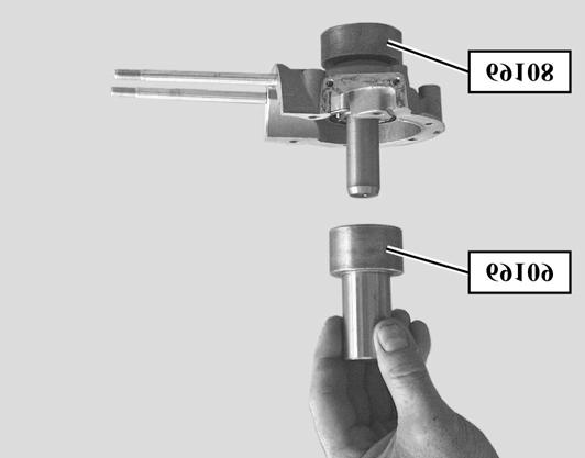
14 DISASSEMBLY To remove the bearings and seals 1) From the casings: - Set the casing down on its mating face - Heat the casing using a heat stripper (80 to 90 C) until the bearing drops out itself - Remove the seal 2) On the crank assembly: Special tooling required - Protective cap P/N Casing extraction and opening tool P/N Shell for Ø 40 mm bearing P/N Shell for Ø 47 mm bearing P/N Fit protective cap P/N to the crank assembly on the side the bearing is to be removed from - Fit tool P/N to the crank assembly Clamp the bearing and tool P/N in the shells P/N or held together by the ring - Tighten the tool screw P/N until the bearing is fully extracted Carry out the same operation to extract the second bearing Note: the bearing external diameter of 47 mm is on the drive pulley side The bearing 40 mm external diameter is on the magneto flywheel side Page: 16

 and push it fully home into the casing half using tool P/N 69109 (small diameter side) 69109 (small diameter side) - Remove the fitting tool and seal")
15 REASSEMBLY RE-ASSEMBLY To fit the bearing and seal in the LH casing Special tooling required - Bearing guide and crank assembly seal P/N Fitting guide P/N Bearing guide and crank assembly seal P/N Note: the tools and parts should be prepared before the operation after heating the casing half, the work must proceed quite quickly - Heat the casing half to 80 to 90 C - Fit the casing half on the guide P/N with the mating surface upwards - Fit the seal guide P/N (the knurled side facing upwards) into the bearing bore - Fit the previously greased seal to guide P/N ( with the lip facing upwards ) and push it fully home into the casing half using tool P/N (small diameter side) (small diameter side) - Remove the fitting tool and seal guide - Fit the bearing to guide P/N and push it fully home into the casing half using tool P/N (large diameter side) Page: 17
16 REASSEMBLY Page: 18

 into the bearing bore - Fit the previously greased seal to guide P/N 69112 (the lip facing upwards) - Push the seal fully home into the casing")
 - Fit the bearing to guide P/N 69115 and push it fully home into the casing using tool P/N 69114 (large diameter")
17 REASSEMBLY To fit the bearing and seal in the RH casing Special tooling required - Bearing fitting tool P/N Fitting guide P/N Fitting guide P/N Fitting guide P/N Bearing guide and crank assembly seal P/N Note: the tools and parts should be prepared before the operation after heating the casing half, the work must proceed quite quickly - Heat the casing half to 80 to 90 C - Fit guide P/N (Ø 16 mm) into base P/N Fit the casing half (with mating surface upwards) on tool P/N Fit the seal guide P/N (the knurled side facing upwards) into the bearing bore - Fit the previously greased seal to guide P/N (the lip facing upwards) - Push the seal fully home into the casing using tool P/N (small diameter side) - Remove the tool P/N and seal guide P/N Without removing the casing from the base, remove the guide P/N (Ø 16 mm) from the top and in its place, through the seal, fit guide P/N (Ø 17 mm) - Fit the bearing to guide P/N and push it fully home into the casing using tool P/N (large diameter side) Page: 19


 Ø 6 x 80 mm - Fit the shoulder centring tool P/N 64710 and butterfly nut P/N 69104 to")
18 REASSEMBLY To fit the crank assembly in the LH casing Special tooling required - Casing extraction and opening tool P/N Butterfly nut P/N Shouldered centring tool P/N Pin Ø 11 mm pitch 100 P/N Pin Ø 10 pitch 125 P/N Casing opening/closing bush P/N Taper dowel for seal P/N Casing opening/closing plate P/N Fit the magneto flywheel, this will act as a support Fit dowel P/N to the crank assembly to prevent damage to the seal - Fit the crank assembly inside the bearing - Fit bush P/N the small diameter side against the casing - Tighten pin P/N against the end of the crank assembly Note: for kickstart engines use pin Ø10 pitch 125 P/N Fit tool P/N fitted with plate P/N over bush P/N Centre assembly with 2 nuts and bolts (5) Ø 6 x 80 mm - Fit the shoulder centring tool P/N and butterfly nut P/N to tool P/N Page: 20


 at (A) and also the other 2 bolts (9) to fit the gasket correctly -")
19 REASSEMBLY - Tighten the butterfly nut P/N in order to bring the crank assembly into contact with the bearing while securing the assembly by the engine casing and ensuring that the connecting rod is correctly positioned. Assembling the casings Special tooling required - Casing extraction and opening tool P/N Butterfly nut P/N Shouldered centring tool P/N Pin Ø 10 pitch 100 P/N Casing opening/closing bush P/N Casing opening/closing plate P/N Fit the drum, this will act as a support - Fit the paper gasket (6) to the LH casing (do not use oil or grease) - Insert the crank assembly into the RH casing (7) bearing Note: take care not to damage the gasket with the pin, if the pin is still on the crank assembly - To facilitate the assembly operation, fit the centring bolt (8) at (A) and also the other 2 bolts (9) to fit the gasket correctly - Tighten the rod P/N on the crank assembly - Fit bush P/N the large diameter side against the casing Page: 21

 - Fit")
 and (B) - Lubricate the crank assembly and check it rotates")
20 REASSEMBLY - Fit tool P/N fitted with plate P/N over bush P/N Centre this assembly with 2 bolts (4) Ø5 x 40 mm - Fit the shouldered centring tool P/N to tool P/N Tighten the butterfly nut P/N until the casings come into contact Note: During assembly, check the casing gasket is correctly positioned To assemble the engine bottom end and engine mount - Remove the 3 previously fitted centring bolts - Locate the engine bottom end between the engine mounting arms - Fit the belt guard bracket (3) - Fit the 6 assembly bolts beginning with the machined bolt (8) - Fit the 3 lockwashers (10) with the 3 nuts on the engine mounting side - Tighten to the recommended torque - Trim the paper gasket in the casing at (A) and (B) - Lubricate the crank assembly and check it rotates freely Page: 22

 the piston (2) - Fit the")
 - Fit the circlips")
21 REASSEMBLY To fit the valve and inlet manifold Note: before fitting the valve, check the position of the 2 stops which must be 8 mm from the valve support - Fit in the following order: - the gasket to the casing (1) - the valve (2) - the manifold gasket (3) - the inlet manifold - Fit the 4 fixing bolts to the inlet manifold To fit the piston - Check the cylinder/piston pairing - Fit the rings (1) the piston (2) - Fit the previously greased bearing cage into the connecting rod little end - Fit the piston to the connecting rod little end, with the arrow pointing towards the exhaust side - Fit the gudgeon pin (3) - Fit the circlips Page: 23
 without grease or oil to the casing which has been")
 in the cylinder To fit the cylinder head 1) Air cooled")
 pointing upwards) - Fit the cylinder head - Fit the 4 lockwashers and the 4 nuts - Tighten the 4 nuts working diagonally, to the")
22 REASSEMBLY Note: - The circlip gaps (4) must face upwards or downwards, but under no circumstances to the side - The circlips must be changed each time they are removed To fit the cylinder - Fit a new bottom gasket (5) without grease or oil to the casing which has been previously cleaned of all impurities - Ensure that the piston ring gaps are opposite the piston positioning spigots - Fit the cylinder (6) and lower it while compressing the rings - Check that the piston runs freely (2) in the cylinder To fit the cylinder head 1) Air cooled engine - Check the condition of the cylinder head mating surface - Fit a new cylinder head gasket (7) to the cylinder (the widest metal ring (A) pointing upwards) - Fit the cylinder head - Fit the 4 lockwashers and the 4 nuts - Tighten the 4 nuts working diagonally, to the recommended torque Page: 24
 round the outer edge of the cylinder head - Fit the cylinder head - Fit the 4 lockwashers and the 4 nuts - Tighten the 4 nuts working diagonally, to the recommended torque Page:")
23 REASSEMBLY 2) Liquid cooled engine - Check the condition of the cylinder head mating surface - Fit a new cylinder head gasket (7) to the cylinder (the widest metal ring pointing upwards) - Fit a new O-ring (8) round the outer edge of the cylinder head - Fit the cylinder head - Fit the 4 lockwashers and the 4 nuts - Tighten the 4 nuts working diagonally, to the recommended torque Page: 25
 Adjust the clutch before assembly (see chapter on")
 - the drum (3) - the adjuster washer (4) - the 4-leg spring (5) - the lining (6)")
24 REASSEMBLY Type 1 - drive pulley without governor, without kickstart Drive pulley composition Fitting method Fitting the non-governor drive pulley (type 1) Adjust the clutch before assembly (see chapter on adjusting the clutch) Fit to the crank assembly in the following order: - the washer (2) (the chamfer (A) facing the casing side) - the drum (3) - the adjuster washer (4) - the 4-leg spring (5) - the lining (6) Page: 26
 in the plate (7) - Fit the countersunk washer (10) to the plate (with the countersink on the casing side) - Fit the spacer (11) - Lock the")
 - Turn the assembly alternately in order to synchronise the pulley notches (1) with the lining drive notches (6) - Fit the spring washer (13) - Fit the washer (14) - Fit the nut (15) - Tighten")
25 REASSEMBLY Prepare the following assembly: - fit the 4 previously greased balls (8) to the thrust plate (9) - fit the plate (7) to the thrust plate (9) - Turn the assembly over and fit the lining (6) Note: the spring legs should be inserted in the slots (A) in the plate (7) - Fit the countersunk washer (10) to the plate (with the countersink on the casing side) - Fit the spacer (11) - Lock the assembly with tool P/N Fit the spring washer (12) over the countersunk washer (10) - Fit the pulley (1) lining up the lining drive notches (6) with the cup drive notches cup drive notches (1C) - Turn the assembly alternately in order to synchronise the pulley notches (1) with the lining drive notches (6) - Fit the spring washer (13) - Fit the washer (14) - Fit the nut (15) - Tighten the nut to the recommended torque Page: 27
 Adjust the clutch before assembly (see chapter on adjusting the")
 - the drum (3) - the adjuster washer (4) - the 2-leg spring (5B) - the 4-leg spring (5A) - the lining (6)")
26 REASSEMBLY Type 2 - drive pulley with governor, without kickstart Drive pulley composition Fitting method Fitting the with-governor drive pulley (type 2) Adjust the clutch before assembly (see chapter on adjusting the clutch) Fit to the crank assembly in the following order: - the washer (2) (the chamfer (A) facing the casing side) - the drum (3) - the adjuster washer (4) - the 2-leg spring (5B) - the 4-leg spring (5A) - the lining (6) Page: 28
 in the plate (7) - Fit the countersunk washer (10) to the plate (with the countersink on the casing side) - Fit the spacer (11) - Lock the")
 - Turn the assembly alternately in order to synchronise the pulley notches (1) with the lining drive notches (6) - Remove tool P/N 69142 - Fit the nut (15)")
27 REASSEMBLY Prepare the following assembly: - fit the 6 previously greased balls (8) to the thrust plate (9) - fit the plate (7) to the thrust plate (9) - Turn the assembly over and fit the lining (6) Note: the spring legs should be inserted in the slots (A) in the plate (7) - Fit the countersunk washer (10) to the plate (with the countersink on the casing side) - Fit the spacer (11) - Lock the assembly with tool P/N Drive pulley with governor Re-assembly the governor (see chapter on Governor assembly) - Fit the pulley/governor assembly (1) lining up the lining drive notches (6) with the cup drive notches cup notches (1C) - Turn the assembly alternately in order to synchronise the pulley notches (1) with the lining drive notches (6) - Remove tool P/N Fit the nut (15) and tighten to the recommended torque Page: 29
 - Fit in the following order: - the plain washer (1) - the fixed flange (2) - the washer (4),")
 - the nut (9) - Lock the bobweight support with pin wrench P/N 755586 - Tighten to the recommended torque")
28 REASSEMBLY Type 3 - drive pulley with governor, with kickstart Drive pulley composition Fitting method To fit the governor (type 3) - Fit in the following order: - the plain washer (1) - the fixed flange (2) - the washer (4), the spacer (5), the rotating flange (3) and the nylatron washer (6) - the bobweight support (7) - the plain washer (8) - the nut (9) - Lock the bobweight support with pin wrench P/N Tighten to the recommended torque Page: 30
 into its housing in the crank assembly straight")
 and its two bolts (3) and the")
 and its 2 bolts")
29 REASSEMBLY To fit the magneto flywheel Coil assembly support - Fit the half-moon key (9) into its housing in the crank assembly straight section - Fit the stator plate (7) and its 2 bolts Type 1: 6-pole assembly - Fit the coil assembly (5) and its two bolts (3) and the sensor (6) two bolts (4) To remove the coil assembly and the stator Type 2: 4-pole assembly - Fit the coil assembly (5) and its 2 bolts (3) Page: 31

30 REASSEMBLY - Fit the rotor (1) ensuring its is correctly positioned over the key - Tighten the nut (2) with the chamfered side facing inwards - Immobiliser le rotor avec l outil réf Tighten the nut to the recommended torque Page: 32
31 MISCELLANEOUS OPERATIONS MISCELLANEOUS OPERATIONS Drive pulley assembly Composition of the drive pulley without governor Composition of the drive pulley with governor Page: 33

 + (5B) depending on model - the lining (6) - the clutch flange (7) - the balls (8) (4 or 6 depending on type) - the drum (9) - the washer (10) - the spacer (53527)")
32 MISCELLANEOUS OPERATIONS Clutch adjustment (with and without governor) types 1 and 2 Special tooling required - Clutch fitting / adjustment rod P/N Clutch adjustment plate P/N Clutch fitting dowel P/N Clutch spacer P/N Washer base 1.5 m P/N Parts required: set of adjuster washers Six thicknesses of washer ( mm) are available from spares department Procedure: - Tighten tool P/N in a vice and fit in the following order: - the washer (2) - the adjustment tool P/N the 1.5 mm base washer - the spring (5A) + (5B) depending on model - the lining (6) - the clutch flange (7) - the balls (8) (4 or 6 depending on type) - the drum (9) - the washer (10) - the spacer (53527) for use on the engine with governor to replace the existing spacer - the nut (15) and tighten the assembly to the recommended torque depending on model - Using shims (A), measure the gap between the lining (6) and the flange (7), and depending on the clearance required, change the 1.5 m base washer for the adjuster washer (4) the thickness of which is determined using the following formula: Formula: Clearance measured - Functional clearance = Adjustment washer thickness (4) Example of measurement for a pulley with governor Clearance measured 1 mm - Functional clearance 0.4 mm = Adjustment washer (4) 0.6 mm The functional clearance between the lining and the plate must be between - 7 and 9/10 de mm for the drive pulley without governor (type 1) -3 and 5/10 mm for the drive pulley with governor (type 2) After adjustment, check the functional clearance Page: 34
 on")
 - Hook the other end of the spring to the second peg (C) on the")
 - Bobweight support plate (1D) - Bobweights (1E) - Bobweights spindles")
 Special tooling required - Governor fitting and removal support P/N 750411")
33 MISCELLANEOUS OPERATIONS Changing the starting jaws (with and without governor) types 1 and 2 To fit the return springs - Fit the large loop on the spring inside slot (A) on the pivot and hook it on the pivot pin (B) (the spring loop openings should be facing the inside of the jaw) - Hook the other end of the spring to the second peg (C) on the jaw - Fit the cup (1C) To assemble the governor - type 2 Governor composition ( main components ) - Bobweight support plate (1D) - Bobweights (1E) - Bobweights spindles (1F) - Governor drive (1H) - Rotating flange (1G) - Fixed flange (1A) - Nylon washers (12 and 13) Special tooling required - Governor fitting and removal support P/N Page: 35
 on the tool - Locate the bobweight mounting plate (1D) in")
 flanges - if necessary, unclip the moving flange (1G) drive system (1H) using a screwdriver Types 2")

34 MISCELLANEOUS OPERATIONS Disassembly - Remove the 2 nylon washers (12 and 13) located at each end of the stub - Tighten tool P/N in a vice - Fit the governor (1) on the tool - Locate the bobweight mounting plate (1D) in the tool 4 pegs - Fold down the nut locking tab (1J) - Remove the 32 mm nut (1K) - Remove the fixed (1A) and rotating (1G) flanges - if necessary, unclip the moving flange (1G) drive system (1H) using a screwdriver Types 2 and 3 - if necessary, remove each bobweight by removing the spindle locking device and spindle (1F) Re-assembly Proceed in reverse order to disassembly Note: tighten the 32 mm nut to the recommended torque and close the washer locking tab Page: 36
 - Pulley sprocket (2) - Lock washer (3) - Nut (4) - Circlip (5) - Stiffener plate (6) -")
 - Remove the stiffener plate (6) and the 3 spring")

35 MISCELLANEOUS OPERATIONS Drive pulley assembly Drive pulley composition ( main components ) - Drive pulley (1) - Pulley sprocket (2) - Lock washer (3) - Nut (4) - Circlip (5) - Stiffener plate (6) - Spring washers (7) - Clutch shoes (8) - Springs (9) - Clutch output shaft and cover (10) To change clutch shoes Disassembly - Remove the 3 circlips (5) - Remove the stiffener plate (6) and the 3 spring washers (7) - Remove the 3 shoes (8) and the springs (9) Re-assembly Proceed in reverse order to disassembly To remove the drive pulley sprocket Special tooling required - Drive pulley sprocket removal tool P/N Page: 37
 on the support lining up the sprocket teeth (2) with the support teeth")
 Re-assembly Proceed in reverse order to disassembly Fit the nut locking plate (4)")
36 MISCELLANEOUS OPERATIONS Disassembly - Remove the clutch shoes - Tighten the support in a vice - Position the pulley (1) on the support lining up the sprocket teeth (2) with the support teeth (3) - Fold down the nut locking tab (4) - Remove the nut (5) with the wrench - Remove the sprocket (2) Re-assembly Proceed in reverse order to disassembly Fit the nut locking plate (4) Page: 38
 Note: Removal of the ignition coil requires removal of the coil(s) located either side In the rest position, ensure the coil is fixed with no play on the coil assembly and that")
 - Unsolder the harness connection wire (2) - Remove the clip (3) - Remove the coil (4) Note: The rest of the coil assembly coils cannot be serviced.")
37 MISCELLANEOUS OPERATIONS To remove and fit a coil 1) 6-pole flywheel - Unsolder the earth wire (1) - Unsolder the harness connection wire (2) - Fold down the metal tab (3) - Remove the coil (4) Note: Removal of the ignition coil requires removal of the coil(s) located either side In the rest position, ensure the coil is fixed with no play on the coil assembly and that the tin solders are good quality Apply a bead of silicon to the earth wire in order to secure it All the coils and the sensor may be changed 2) 4-pole flywheel Remove the ignition coil - Unsolder the earth wire (1) - Unsolder the harness connection wire (2) - Remove the clip (3) - Remove the coil (4) Note: The rest of the coil assembly coils cannot be serviced. Page: 39

 - Remove the valve (4) from the decompressor - Remove the")
 from the cylinder")
38 MISCELLANEOUS OPERATIONS To change the decompressor assembly Special tooling required Decompressor removal/fitting tool P/N Remove the cylinder head - Cut off the end of the pin (1), compress the spring (2), remove the pin (1) and the lever (3) - Remove the valve (4) from the decompressor - Remove the spring (2) from the compressor body (5) - Remove the decompressor casing (5) from the cylinder head Note: Do not remove the copper seal (6) from the cylinder head Page: 40
39 MISCELLANEOUS OPERATIONS When re-assembling: NB: coat the decompressor casing threads (5) with gasket compound - Fit the decompressor casing (5) and tighten it to the recommended torque - Fit the spring (2), the valve (4) - Fit the lever (3) and the pin (1) - Flatten the end of the pin (1) with tool P/N and a drift Page: 41


40 RECOMMENDED REF: With a constant concern for improvement Peugeot Motocycles reserves the right to delete, modify, or add any quoted reference DC/PS/ATR printed in E.U. 07/2001 (photos non- contractual) Reproductions ou traductions, même partielles, interdites sans autorisation écrite de Peugeot Motocycles
WORKSHOP MANUAL TECHNICAL NETWORK LEADERSHIP WORKSHOP MANUAL 125 CC/150 CC 4-STROKE ENGINE
 WORKSHOP MANUAL TECHNICAL NETWORK LEADERSHIP WORKSHOP MANUAL - 5 CC/50 CC 4-STROKE ENGINE Workshop manual Technical network leadership TABLE OF CONTENTS TABLE OF CONTENTS TABLE OF CONTENTS... CHARACTERISTICS...
CONTENTS. Special tools Technical Data. 7 Clutch, Automatic plate (120mm diameter) 8
 8") 1 CONTENTS Special tools.. 3-6 Technical Data. 7 Clutch, Automatic plate (120mm diameter) 8 Description, Operation 8 Clutch, Automatic plate (120mm diameter) with variable speed transmission. 9 Description,
1 CONTENTS Special tools.. 3-6 Technical Data. 7 Clutch, Automatic plate (120mm diameter) 8 Description, Operation 8 Clutch, Automatic plate (120mm diameter) with variable speed transmission. 9 Description,
WORKSHOP MANUAL 100 cm3. Moteur FB3 - FB6
 WORKSHOP MANUAL 100 cm3 Moteur FB3 - FB6 GB INTRODUCTION This workshop manual concerns the FB engine which is fitted on several 100cm³ vehicles - FB 3..SV100 - FB 6..SPEEDFIGHT - TREKKER - ELYSÉO - VIVACITY
Drawing A Crankcase 041 AV SCS
 Drawing A Crankcase 1 Drawing A Crankcase Reference Item number Qty Description 1 1110 020 2105 1 Crankcase 2-5, 9, 10, 12 2 9371 470 3120 2 Cylindrical pin 6x20 3 9048 216 1010 8 Pan head screw M5x18
Volkswagen New Beetle 2.0 Liter 4-cyl General, Engine (Engine Code AEG) 13 Engine-Crankshaft, Cylinder block (Page GR-13)
 13 Engine-Crankshaft, Cylinder block (Page GR-13)") 13 Engine-Crankshaft, Cylinder block (Page GR-13) Engine, disassembly and assembly 10-222 A/21 guide from 10-222 A support tool, modifying Ribbed belt, removing and installing Semi-automatic toothed belt
13 Engine-Crankshaft, Cylinder block (Page GR-13) Engine, disassembly and assembly 10-222 A/21 guide from 10-222 A support tool, modifying Ribbed belt, removing and installing Semi-automatic toothed belt
REEDSTER 125cc. versions: F1 - F2 - F3 - F4 OVERHAULING MANUAL
 REEDSTER 125cc versions: F1 - F2 - F3 - F4 OVERHAULING MANUAL 07/11/07 21/01/2009 1 INDEX Page 1. - REEDSTER 125cc ENGINE DISASSEMBLY 1 2. - CRANKSHAFT DISASSEMBLY / ASSEMBLY 13 2.1 - CRANKSHAFT DISASSEMBLY
Printed from MediaCat
 Illustration A Crankcase Illustration A Crankcase Ref.Nr. Item code Quantity Description 1 1106 020 2506 1 Crankcase (2) 2-11 2 0000 988 5217 1 Connector (2) 3 0000 988 5200 2 Connector (2) 4 1106 641
SPARE PARTS LIST POLE PRUNER/POLE SAWS 327 P4
 SPARE PARTS LIST POLE PRUNER/POLE SAWS ACCESSORIES ACCESSORIES Ref Part No Description Remark QTY KIT 1 537 04 07-10 ACCESSORY BAG 1 2 501 69 17-01 COMBINATION WRENCH 1 3 502 21 58-01 WRENCH 1 4 503 97
SPARE PARTS LIST. POLE PRUNER/POLE SAWS 327 P5x
 SPARE PARTS LIST POLE PRUNER/POLE SAWS ACCESSORIES ACCESSORIES Ref Part No Description Remark QTY KIT 1 537 04 07-10 ACCESSORY BAG 1 2 501 69 17-01 COMBINATION WRENCH 1 3 502 21 58-01 WRENCH 1 4 503 98
Engine Dismantle and Assemble ( )
") Engine Dismantle and Assemble (2 34 8) Special Tools 2-036A Remover for pilot bearing 2-37 Oil seal installer/aligner 237 2036A 2-044A Installer/Aligner, Pilot Bearing/Clutch Plate 244 2-44 Inlet manifold
Engine Dismantle and Assemble (2 34 8) Special Tools 2-036A Remover for pilot bearing 2-37 Oil seal installer/aligner 237 2036A 2-044A Installer/Aligner, Pilot Bearing/Clutch Plate 244 2-44 Inlet manifold
file://c:\programdata\proquestms\partsmanagerpro\print\ ~13~11~5.html
 C60TLRZ 00 file://c:\programdata\proquestms\partsmanagerpro\print\8-9-0 ~~~5.html Page of 6 8/9/0 C60TLRZ 00 / TOP COWLING 0 Yamaha Motor Corporation, U.S.A. All rights reserved. C60TLRZ 00 file://c:\programdata\proquestms\partsmanagerpro\print\8-9-0
Sales division Technical network leadership WORKSHOP MANUAL 125/151 CC 4-STROKE ENGINE 2 VALVES SYM
 Sales division Technical network leadership WORKSHOP MANUAL - 5/5 CC 4-STROKE ENGINE VALVES SYM TABLE OF CONTENTS TABLE OF CONTENTS TABLE OF CONTENTS... PRODUCTS DANGER SYMBOLS USED... 3 CHARACTERISTICS...
Super 1050 Chain Saw UT Page 1 of 16 Carburetor Chamber
 Super 1050 Chain Saw UT-10139 Page 1 of 16 Carburetor Chamber Super 1050 Chain Saw UT-10139 Page 2 of 16 Carburetor Chamber 1 58319A 1 RING- Retaining 2 592301 1 COVER- Air filter 3 A70326 1 NUT- Cover
1.6L 4-CYL - VIN [E]
![1.6L 4-CYL - VIN [E]](/thumbs/81/84172348.jpg "1.6L 4-CYL - VIN [E]") 1.6L 4-CYL - VIN [E] 1993 Nissan Sentra 1993 NISSAN ENGINES 1.6L 4-Cylinder NX, Sentra * PLEASE READ THIS FIRST * NOTE: For engine repair procedures not covered in this article, see ENGINE OVERHAUL PROCEDURES
1.6L 4-CYL - VIN [E] 1993 Nissan Sentra 1993 NISSAN ENGINES 1.6L 4-Cylinder NX, Sentra * PLEASE READ THIS FIRST * NOTE: For engine repair procedures not covered in this article, see ENGINE OVERHAUL PROCEDURES
90 Y-12 Youth. Model Number A2005H4B2BUSR (Red) Model Number A2005H4B2BUSZ (Cat Green) Illustrated Parts Manual
 Model Number A2005H4B2BUSZ (Cat Green) Illustrated Parts Manual") 90 Y-12 Youth Model Number A2005H4B2BUSR (Red) Model Number A2005H4B2BUSZ (Cat Green) Illustrated Parts Manual 2005 TABLE OF CONTENTS 2005 ATV 90 Y-12 Youth Red (Model No. A2005H4B2BUSR) Cat Green (Model
90 Y-12 Youth Model Number A2005H4B2BUSR (Red) Model Number A2005H4B2BUSZ (Cat Green) Illustrated Parts Manual 2005 TABLE OF CONTENTS 2005 ATV 90 Y-12 Youth Red (Model No. A2005H4B2BUSR) Cat Green (Model
Fig. 6: Assembling Piston & Rod. NOTE: Notch must face forward Toyota Starlet CRANKSHAFT MAIN BEARINGS
 connecting rods are marked for reassembly. 3. Thoroughly clean and inspect all components. Coat pin with engine oil and heat piston to 158-176 F (70-80 C). Pin should push fit with thumb pressure through
Engine Dismantle and Assemble ( )
") Engine Dismantle and Assemble (21 134 8) Special Tools 15-030A Universal flange-holding wrench 21147 21-147 Vibration damper remover 15030A 16-067 Locator for clutch disc 21-167 Wrench for cylinder head
Engine Dismantle and Assemble (21 134 8) Special Tools 15-030A Universal flange-holding wrench 21147 21-147 Vibration damper remover 15030A 16-067 Locator for clutch disc 21-167 Wrench for cylinder head
Engine. Special Tool(s) Compressor, Piston Ring 303-D032 (D81L-6002-C) or equivalent. Compressor, Valve Spring (T93P-6565-AR)
 Compressor, Piston Ring 303-D032 (D81L-6002-C) or equivalent. Compressor, Valve Spring (T93P-6565-AR)") SECTION 303-01C: Engine 5.4L (4V) 2009 Mustang Workshop Manual ASSEMBLY Procedure revision date: 12/12/2008 Engine Special Tool(s) Compressor, Piston Ring 303-D032 (D81L-6002-C) or equivalent Compressor,
SECTION 303-01C: Engine 5.4L (4V) 2009 Mustang Workshop Manual ASSEMBLY Procedure revision date: 12/12/2008 Engine Special Tool(s) Compressor, Piston Ring 303-D032 (D81L-6002-C) or equivalent Compressor,
Printed from MediaCat
 Illustration A Crankcase, Crankshaft Illustration A Crankcase, Crankshaft Ref.Nr. Item code Quantity Description 1 1117 020 2106 1 Crankcase 2-9 2 9022 341 1050 4 Spline screw IS-M5x25 3 0000 988 5211
1984 Dodge W250 PICKUP
 1984 Dodge W250 PICKUP Submodel: Engine Type: V8 Liters: 5.2 Fuel Delivery: CARB Fuel: GAS Dana 44 MODELS THROUGH 1984 2. Raise and safely support the vehicle, then remove the wheel hub and bearings as
613GC Key A Parts Starter & Ignition Assembly
 613GC Key A Parts Starter & Ignition Assembly 73866 Screw (same as B26) A01 505514 Starter Rope Handle A02 73904 Starter Rope A03 73909 Starter Coil Spring & Housing A04 71451 Starter Case Plate A05 73910
OVERHAUL MANUAL 28/09/05 mod. A 1 MAN-044 ING
 OVERHAUL MANUAL 28/09/05 mod. A 1 INDEX Page 1. - PARILLA X30 125cc RL TaG ENGINE DISASSEMBY 1 2. - CRANKSHAFT DISASSEMBLY/ ASSEMBLY 10 2.1- CRANKSHAFT DISASSEMBLY 10 2.2- CRANKSHAFT ASSEMBLY 12 3. - PARILLA
290 Chain Saw UT A Page 1 of 14 Accessories & Tools
 290 Chain Saw UT-10661-A Page 1 of 14 Accessories & Tools 290 Chain Saw UT-10661-A Page 2 of 14 Accessories & Tools Ref # Part Number Qty S/P/F Description 98293 1 BUMPER SPIKE 98488 1 ROTOR REMOVAL TOOL
REF. NO. DESCRIPTION TOP COWLING 2 MOLDING, AIR DUCT 3 RIVET 4 SEAL 5 HOLDER, CLAMP BAND 6 BOLT, WITH WASHER 7 HOOK
 SUZHOU ALLPASS MACHINERY CO.,LTD Add:No.85,Jishui Road,Jinfeng Industrial Park,Mudu Town,Suzhou 215102,Jiangsu,P.R.China T15 SPARE PARTS EXPLODED DRAWING FIG. 1 1 TOP COWLING TOP COWLING 2 MOLDING, AIR
This file is available for free download at
 This file is available for free download at http://www.iluvmyrx7.com This file is fully text-searchable select Edit and Find and type in what you re looking for. This file is intended more for online viewing
20.Cylinder Block. Cylinder Block A: REMOVAL ME(H4DOTC)-63 ST CRANKSHAFT STOPPER
-63 ST CRANKSHAFT STOPPER") Cylinder Block MECHANICAL 20.Cylinder Block A: REMOVAL Before conducting this procedure, drain engine oil completely. 1) Remove the intake manifold. 2)
Cylinder Block MECHANICAL 20.Cylinder Block A: REMOVAL Before conducting this procedure, drain engine oil completely. 1) Remove the intake manifold. 2)
9/8/ MSHZ 2001 / TOP COWLING Yamaha Motor Corporation, U.S.A. All rights reserved.
 9.9MSHZ 00 Page of 47 9/8/04 9.9MSHZ 00 / TOP COWLING 04 Yamaha Motor Corporation, U.S.A. All rights reserved. 9.9MSHZ 00 Page of 47 9/8/04 Part List 9.9MSHZ 00 / TOP COWLING REF - NO PART NUMBER PART
615 Service Manual SERVICE MANUAL. 615 Series Axle
 SERVICE MANUAL 615 Series Axle Issue 1 - February 2002 CONTENT: 1 INTRODUCTION... Page - 1-2 GENERAL DESCRIPTION... Page - 1-3 IDENTIFICATION... Page - 1-4 GENERAL SERVICE INFORMATION... 4.1 Routine Maintenance...
MGA Twin Cam Engine Assembly.
 MGA Twin Cam Engine Assembly. The following article is a collection of notes of things to be observed in the assembling of MGA Twin Cam engines. To be read in conjunction with the Workshop Manual. It does
SPARE PARTS LIST BRUSHCUTTERS/CLEARING SAWS 240 R,
 SPARE PARTS LIST BRUSHCUTTERS/CLEARING SAWS 240 R, 2005-09 ACCESSORIES 240 R, 2005-09 ACCESSORIES 240 R, 2005-09 Ref Part No Description Remark QTY KIT 501 19 22-01 TOOL CASING 1 501 60 02-03 SCREWDRIVER
HKS 700E. Service Manual June Ver. 2.04
 HKS 700E Service Manual 009 June Ver..04 HKS CO.,LTD 78 KITAYAMA FUJINOMIYA SHIZUOKA JAPAN 48-09 TEL +8(0)544-54-78 FAX +8(0)544-54-40 hks_aviation@hks-power.co.jp http://www.hks-power.co.jp/hks_aviation/
Part list for Kawasaki H2, 1972
 Part list for Kawasaki H2, 972 . Cylinder head, cylinder. . Cylinder head, cylinder. 9205-049 NUT 0 m/m 2 2 40B400 WASHER-plain 4 m/m 2 3 46E400 WASHER-spring 4 m/m 2 4 92070-036 SPARK PLUG NGK B9 HS 3
C19 TPS mars 2003 Z063800
 TPS 2501 29 mars 2003 Z063800 TPS-2501 CYLINDER/PISTON/CRANK SHAFT 01 Ref. Part No. Description Q'ty 001 157-01570-90 SPARK PLUG CAP ASS'Y 1 002 018-00546-21 SPARK PLUG BMR6A 1 006 001-07060-90 CYLINDER
ASSEMBLY Procedure revision date: 11/22/2001
 Page 1 of 39 Evan Groenke From: Daniel Lelovic [dlelovic@rogers.com] Sent: May 8, 2005 12:08 PM To: 'Evan Groenke' Subject: 2.5L Engine Re-assembly SECTION 303-01B: Engine 2.5L 2000 Contour/Mystique Workshop
HOFFMANN POWER PRODUCTS PARTS LIST 2014
 HOFFMANN POWER PRODUCTS PARTS LIST 2014 HOFFMANN CHAINSAW PN7200 ALL PARTS ARE SUBJECT TO STANDARD HOFFMANN TERMS AND CONDITIONS OF SALE 2010 Replacement parts are not manufactured, sold or warranted by
245 Chain Saw UT Page 1 of 16 Air Filter & Handles & Oil Pump
 245 Chain Saw UT-10631 Page 1 of 16 Air Filter & Handles & Oil Pump 245 Chain Saw UT-10631 Page 2 of 16 Air Filter & Handles & Oil Pump Ref # Part Number Qty Description 1 80870 1 SCREW- 10-32 x 3/8 2
TPS-2501,S CYLINDER/PISTON/CRANK SHAFT
 TPS-2501,S CYLINDER/PISTON/CRANK SHAFT 01 Ref. Part No. Description Q'ty 001 157-01570-90 SPARK PLUG CAP ASS'Y 1 002 018-00546-21 SPARK PLUG BMR6A 1 006 001-07060-90 CYLINDER SET 1 007 994-64050-204 SCREW
ENGINE REASSEMBLY CRANKCASE PREASSEMBLY DIAGRAM DESCRIPTION. into the half crankcase clutch side and secure with the snap ring
 ENGINE REASSEMBLY CRANKCASE PREASSEMBLY Drive the OUTPUT SHAFT BEARING into the half crankcase clutch side and secure with the snap ring 143176 LUBRICATE THE HOUSING LEAVE THE PRINT ON THE BEARING VISIBLE
ATV 50 Y-6 YOUTH CAT GREEN (A2004ATA2BUSZ) Page 1 of 50 A-ARM, FLOOR PANEL, AND BUMPER ASSEMBLY
 Page 1 of 50 A-ARM, FLOOR PANEL, AND BUMPER ASSEMBLY") 2004 ATV 50 Y-6 YOUTH CAT GREEN (A2004ATA2BUSZ) Page 1 of 50 A-ARM, FLOOR PANEL, AND BUMPER ASSEMBLY 2004 ATV 50 Y-6 YOUTH CAT GREEN (A2004ATA2BUSZ) Page 2 of 50 A-ARM, FLOOR PANEL, AND BUMPER ASSEMBLY
2004 ATV 50 Y-6 YOUTH CAT GREEN (A2004ATA2BUSZ) Page 1 of 50 A-ARM, FLOOR PANEL, AND BUMPER ASSEMBLY 2004 ATV 50 Y-6 YOUTH CAT GREEN (A2004ATA2BUSZ) Page 2 of 50 A-ARM, FLOOR PANEL, AND BUMPER ASSEMBLY
Vespa LX 50 4valvole. Refitting the valves. Inspecting the cam shaft. Characteristic. Engine
 Refitting the valves - Lubricate the valve guides with graphite grease. - Place the lower caps of the valve spring on the head. - Use the punch to fit the 4 sealing rings one at a time. - Fit the valves,
Small Engine Parts. Super 2 Chain Saw UT Page 1 of 12 Engine Internals
 Small Engine Parts Super 2 Chain Saw UT-10654 Page 1 of 12 Engine Internals Super 2 Chain Saw UT-10654 Page 2 of 12 Engine Internals Ref # Part Number Qty Description 1 A95072 1 CRANKCASE & CYLINDER ASSY.
G85CS Parts list. Frank Kyul, Netherlands
 G85CS Parts list Frank Kyul, Netherlands http://home.wanadoo.nl/fxkuyl/ CYLINDER BARREL & HEAD 022298 Barrel Cylinder 1 022515 Washer Cylinder Base 1 015351 Nut. Sleeve Cylinder Head 4 042157 Washer Sleeve
SPARE PARTS LIST BRUSHCUTTERS/CLEARING SAWS 223 L,
 SPARE PARTS LIST BRUSHCUTTERS/CLEARING SAWS 223 L, 2006-01 ACCESSORIES 223 L, 2006-01 ACCESSORIES 223 L, 2006-01 Ref Part No Description Remark QTY KIT 1 501 78 33-01 SUSPENSION BAIL 1 2 503 21 83-16 SCREW
SPARE PARTS LIST BRUSHCUTTERS/CLEARING SAWS BC2145,
 SPARE PARTS LIST BRUSHCUTTERS/CLEARING SAWS BC2145, 2008-05 ACCESSORIES BC2145, 2008-05 ACCESSORIES BC2145, 2008-05 Ref Part No Description Remark QTY KIT 1 502 21 60-13 ACCESSORY BAG 1 2 501 60 02-03
Carburettor. Cylinder. Frame. Engine Brake System. PTO (Power Take-Off) Electrical System. Steering. Seat. Lifting Device.
 Electrical System. Steering. Seat. Lifting Device.") Documents Carburettor Cylinder Frame Engine Brake System Technical information Article number 13-1318-13 Season 1990-1991 Brand Code Stiga Product Name PARK 12HST SubCategory Park Compact Type Machine
Documents Carburettor Cylinder Frame Engine Brake System Technical information Article number 13-1318-13 Season 1990-1991 Brand Code Stiga Product Name PARK 12HST SubCategory Park Compact Type Machine
CYLINDER. Ref. Part No. Number Description Qty Remarks
 A1 CYLINDER 1 (5F7-11111-00-00) HEAD, CYLINDER 1......... 2 2 90338-06041-00 PLUG.................... 2 3 90430-06166-00 GASKET................. 2 4 93210-62323-00 O-RING (93210-63442-00)..... 2 5 93211-14421-00
 Page 1 of 75 303-01D Engine - 5.2L 32V Ti-VCT 2016 Mustang Assembly Procedure revision date: 12/15/2016 Special Tool(s) / General Equipment Engine Base Part Number: 6L084 205-142 (T80T-4000-J) Installer,
XL Chain Saw UT Page 1 of 12 Engine Internals
 XL Chain Saw UT-10655 Page 1 of 12 Engine Internals XL Chain Saw UT-10655 Page 2 of 12 Engine Internals Ref # Part Number Qty S/P/F Description 1 A95071A 1 CRANKCASE & CYLINDER ASSY. 2 80571 3 /P SCREW-
SPARE PARTS LIST TRIMMERS/EDGERS 325 E X-SERIES,
 SPARE PARTS LIST TRIMMERS/EDGERS 325 E X-SERIES, 2001-01 ACCESSORIES 325 E X-SERIES, 2001-01 ACCESSORIES 325 E X-SERIES, 2001-01 Ref Part No Description Remark QTY KIT 501 60 02-03 SCREWDRIVER 1 502 11
Chapter 5 Part B: Ignition system - transistorised type
 5B 1 Chapter 5 Part B: Ignition system - transistorised type Contents Coil - testing........................................... 9 Distributor - overhaul..................................... 7 Distributor
XL12 Chain Saw UT Page 1 of 21 Carburetor Chamber
 XL12 Chain Saw UT-10080 Page 1 of 21 Carburetor Chamber XL12 Chain Saw UT-10080 Page 2 of 21 Carburetor Chamber 1 59274 1 GASKET- Spacer 2 59718 1 SPACER 3 63260A 1 RETAINER- Reed valve 4 63253 1 SEAT-
SXLAO Chain Saw UT Page 1 of 21 Carburetor Chamber
 SXLAO Chain Saw UT-10045 Page 1 of 21 Carburetor Chamber SXLAO Chain Saw UT-10045 Page 2 of 21 Carburetor Chamber 1 59274 1 GASKET- Spacer 2 59718 1 SPACER 3 63260A 1 RETAINER- Reed valve 4 63253 1 SEAT-
SPARE PARTS LIST BRUSHCUTTERS/CLEARING SAWS 325 RX,
 SPARE PARTS LIST BRUSHCUTTERS/CLEARING SAWS 325 RX, 2008-03 ACCESSORIES 325 RX, 2008-03 ACCESSORIES 325 RX, 2008-03 Ref Part No Description Remark QTY KIT 1 531 00 92-48 FILTER OIL 1 2 502 28 59-01 STOP
CHAIN SAWS G561AVS G621AVS
 2626-93121 CHAIN SAWS G561AVS G621AVS APPLICABLE SERIAL NUMBERS: OCTOBER 1998 G561AVS 814608 and up G621AVS 820954 and up Fig.1 1 Fig.2 2 Fig.1 1 1 2616-12112 2618-12115 CYLINDER 1 K4 2 3356-12141 GROMMET
Online version - not for reprint
 (3) A Shortblock 0... B Shortblock 03, 03 L... 3 C Shortblock 0... 4 D Engine housing... D Engine housing... E Quick tensioner parts... F Oil pump... G Clutch... H Chain brake... J Muffler... K Ignition
Printed from MediaCat
 Illustration A Crankcase Illustration A Crankcase Ref.Nr. Item code Quantity Description 1 1119 020 2118 1 Crankcase (1,3,5) 2-11 1 1119 020 2109 1 Crankcase (6,8,9) 2-11 1 1119 020 2119 1 Crankcase (2,4)
Printed from MediaCat
 Illustration A Crankcase, Cylinder Illustration A Crankcase, Cylinder Ref.Nr. Item code Quantity Description 1 1113 020 2107 1 Crankcase (1,2,4,5,7,8) 2-11 1 1113 020 2108 1 Crankcase (3,6) 2-11 2 1113
lbs sq. Camshaft bush ID 0.5 ± Clearance bush to camshaft ±
 GENERAL Cubic capacity 347 C.C. Stroke 93 mm. / 3.6614 Cylinder bore Compression ratio Max compression at kick starter speed 2 23 /32 = 2.7187 ± 0.0005 (Re-bore to + 0.02 when wear exceeds 0.008 ). Note:
2.2L 4-CYL - VIN [S]
![2.2L 4-CYL - VIN [S]](/thumbs/72/67564355.jpg "2.2L 4-CYL - VIN [S]") 2.2L 4-CYL - VIN [S] 1994 Toyota Celica 1994 ENGINES Toyota 2.2L 4-Cylinder Celica NOTE: For repair procedures not covered in this article, see ENGINE OVERHAUL PROCEDURES - GENERAL INFORMATION article
2.2L 4-CYL - VIN [S] 1994 Toyota Celica 1994 ENGINES Toyota 2.2L 4-Cylinder Celica NOTE: For repair procedures not covered in this article, see ENGINE OVERHAUL PROCEDURES - GENERAL INFORMATION article
9. DRIVE AND DRIVEN PULLEYS/ KICK STARTER AGILITY CITY ~6.0kg-m g-m g-m 9-0
 9 5.0~6.0kg-m 3.5-4.5g-m 9 3.5-4.0g-m 9-0 SERVICE INFORMATION...9-1 DRIVE BELT...9-5 TROUBLESHOOTING...9-1 DRIVE PULLEY...9-6 LEFT CRANKCASE COVER...9-2 CLUTCH/DRIVEN PULLEY...9-9...9-2 SERVICE INFORMATION
rev 1_09/20/2017 PS-35C EA3500SR
 C 1 Tank, Handle 5 7 6 8 17 9 1 2 10 11 12 13 18 19 20 3 21 4 22 23 14 16 2 1 Tank, Handle 1 1 168507-3 TANK CAP COMPLETE 1 1 INC. 2 1 2 213080-9 O RING 29.5 1 1 1 3 163447-0 GASOLINE FILTER 1 1 1 4 195757-7
ENGINE - V8. Seal - crankshaft - rear. Refit 1. Ensure both seal location and running surface on crankshaft are clean.
 REPAIRS Seal - crankshaft - rear 1. Ensure both seal location and running surface on crankshaft are clean. 1. Automatic gearbox models: converter drive plate. ENGINE - V8, REPAIRS, Plate - drive - automatic.
Replacement Parts & Accessories Price List
 Replacement Parts & Accessories Price List 680GC Petrol Concrete Saw Serial numbers starting with 967 & 977 Effective January 1, 2011 TABLE OF CONTENTS 680GC Petrol Concrete Saw ITEM DESCRIPTION KEY PAGE
Repair Manual 11/99 PS-34. Page 1
 Repair Manual /99 PS-4 Page Table of contents Index Technical Data page Special tools 4 Repair instructions, general 0 Chain brake 6 0 Centrifugal clutch 8 0 Oil pump 9-04 Ignition system - 0 Starting
B06 TBC 300/SDH (TBC 4500) 28 septembre 2002 V099900
 28 septembre 2002 V099900") TBC 300/SDH (TBC 4500) 28 septembre 2002 V099900 TBC-300,SDH CYLINDER/PISTON/CRANK SHAFT 01 Ref. Part No. Description Q'ty Serial No. 001 157-0097A-90 SPARK PLUG CAP ASS'Y 1 002 018-01700-21 SPARK PLUG
TBC 300/SDH (TBC 4500) 28 septembre 2002 V099900 TBC-300,SDH CYLINDER/PISTON/CRANK SHAFT 01 Ref. Part No. Description Q'ty Serial No. 001 157-0097A-90 SPARK PLUG CAP ASS'Y 1 002 018-01700-21 SPARK PLUG
SPARE PARTS LIST TRIMMERS/EDGERS 323 LD,
 SPARE PARTS LIST TRIMMERS/EDGERS 323 LD, 2008-03 ACCESSORIES 323 LD, 2008-03 ACCESSORIES 323 LD, 2008-03 Ref Part No Description Remark QTY KIT 1 531 00 92-48 FILTER OIL 1 2 502 28 59-01 STOP 1 3 501 60
Super EZ Chain Saw UT Page 1 of 18 Tools And Accessories
 Super EZ Chain Saw UT-10440 Page 1 of 18 Tools And Accessories Super EZ Chain Saw UT-10440 Page 2 of 18 Tools And Accessories 24299 24299 ANVIL- Crankshaft installation 24304 24304 BIT- #2 pozidrive 24295
B10 SUM 400/N (TBC 4500) 13 mai 2002 W107150
 13 mai 2002 W107150") SUM 400/N (TBC 4500) 13 mai 2002 W107150 SUM-400,N CYLINDER/PISTON/CRANK SHAFT 01 Ref. Part No. Description Q'ty 001 157-0097A-90 SPARK PLUG CAP ASS'Y 1 002 018-01700-21 SPARK PLUG BMR7A 1 004 001-0135U-90
SUM 400/N (TBC 4500) 13 mai 2002 W107150 SUM-400,N CYLINDER/PISTON/CRANK SHAFT 01 Ref. Part No. Description Q'ty 001 157-0097A-90 SPARK PLUG CAP ASS'Y 1 002 018-01700-21 SPARK PLUG BMR7A 1 004 001-0135U-90
1983 BMW 320i. 1.8L 4-CYL 1983 Engines - 1.8L 4-Cylinder Engines - 1.8L 4-Cylinder
 ENGINE IDENTIFICATION 1.8L 4-CYL 1983 Engines - 1.8L 4-Cylinder For engine repair procedures not covered in this article, see ENGINE OVERHAUL PROCEDURES - GENERAL INFORMATION article in the GENERAL INFORMATION
Engine. Special Tool(s) Adapter for (T97T-6256-A) Adapter for (T97T-6256-D)
 Adapter for (T97T-6256-A) Adapter for (T97T-6256-D)") SECTION 303-01A: Engine 4.0L SOHC 2009 Mustang Workshop Manual ASSEMBLY Procedure revision date: 05/10/2010 Engine Special Tool(s) Adapter for 303-564 303-578 (T97T-6256-A) Adapter for 303-577 303-576
SECTION 303-01A: Engine 4.0L SOHC 2009 Mustang Workshop Manual ASSEMBLY Procedure revision date: 05/10/2010 Engine Special Tool(s) Adapter for 303-564 303-578 (T97T-6256-A) Adapter for 303-577 303-576
MicrofichesExcel. Tavola Posizione Codice Quant Ing
 Tavola Posizione Codice Quant Ing 1 1 T1P52MI-A-011200 1 LH Crankcase 1 2 T1P52MI-A-011300 1 RH Crankcase 1 3 T11119 1 Crankcase gasket 1 4 TOR00037 4 Screw M5 6 1 5 T1P52MI-011400 2 Bush 1 6 T11118 2
CS340ES. Property of - Not for Resale A1
 A1 CYLINDER HEAD - CYLINDER 1 8G8-11111-00-00 HEAD, CYLINDER 1......... 1 2 8G8-11121-00-00 HEAD, CYLINDER 2......... 1 3 NGK-BR9ES-00-00 PLUG, SPARK............. 2 4 8G8-11181-01-00 GASKET, CYLINDER HEAD
SPARE PARTS LIST BRUSHCUTTERS/CLEARING SAWS 345 FR
 SPARE PARTS LIST BRUSHCUTTERS/CLEARING SAWS ACCESSORIES ACCESSORIES Ref Part No Description Remark QTY KIT 1 502 15 70-02 SUPPORT CUP 1 2 544 35 91-01 TRANSPORT GUARD 1 3 537 31 29-01 TRANSPORT GUARD 1
Drawing A Crankcase. Drawing A Crankcase
 Drawing A Crankcase Drawing A Crankcase 1 4238 020 2901 1 Crankcase 2-4 2 9503 003 0351 2 Grooved ball bearing 15x36.3x11 3 0000 953 6606 3 Stud 4 9630 951 1696 1 Oil seal 15x26x7 5 4238 020 2605 1 Crankcase,
300 Chain Saw UT Page 1 of 16 Accessories I
 300 Chain Saw UT-10687 Page 1 of 16 Accessories I 300 Chain Saw UT-10687 Page 2 of 16 Accessories I Ref # Part Number Qty Description A-02177 A02177 1 BUMPER SPIKE KIT 9477299 9477299 1 RUBBER TUBING (10')
Super EZ Chain Saw UT Page 1 of 19 Carburetor
 Super EZ Chain Saw UT-10580 Page 1 of 19 Carburetor Super EZ Chain Saw UT-10580 Page 2 of 19 Carburetor 1 93203A 1 /P Repair Kit Includes items 1-16. 2 93203A 1 /P Repair Kit Includes items 1-16. 3 93203A
SERVICE MANUAL. 915 Series Axle
 SERVICE MANUAL 915 Series Axle Issue 1 September 2003 CONTENT: 1 INTRODUCTION Page 3-2 GENERAL DESCRIPTION Page 3-3 IDENTIFICATION Page 3-4 GENERAL SERVICE INFORMATION Page 5 -.1 4.1 Routine Maintenance
1.8L & 2.2L 4-CYL Article Text 1998 Subaru Impreza
 1.8L & 2.2L 4-CYL Article Text 1998 Subaru Impreza ARTICLE BEGINNING 1995-98 ENGINES Subaru - 1.8L & 2.2L 4-Cylinder 1995-97: Impreza (1.8L) 1995-98: Impreza (2.2L), Legacy (2.2L) * PLEASE READ THIS FIRST
Updated September DISCOUNT TRACTOR PARTS PH Aidrie Rd, Box Ranui, Auckland
 FERGUSON FE 35 Petrol Engine Models Parts catalogue and price list Updated September 2011 DISCOUNT TRACTOR PARTS PH 0800 872272 7 Aidrie Rd, Box 70059 Ranui, Auckland Ph 09 8337483 Fax 09 8335186 E mail
Chain Box and Knife. Item # Description Part Number 180-D & GS
 Chain Box and Knife Item # Description Part Number 180-D & GS 1 Groove pin 2275-03160 2 Hex cap screw 2175-03061 3 Washer 2275-03060 4 Setscrew 2175-07163 5 Chain box 4975-00355 6 Berkel logo 3175-00152
B11 SUM 500L (TBC 4500) 9 septembre 2003 Y258200
 9 septembre 2003 Y258200") SUM 500L (TBC 4500) 9 septembre 2003 Y258200 SUM-500L CYLINDER/PISTON/CRANK SHAFT 01 Ref. Part No. Description Q'ty 006 157-11666-90 SPARK PLUG CAP ASS'Y 1 007 255-04200-20 SPARK PLUG RUBBER COVER 1 008
SUM 500L (TBC 4500) 9 septembre 2003 Y258200 SUM-500L CYLINDER/PISTON/CRANK SHAFT 01 Ref. Part No. Description Q'ty 006 157-11666-90 SPARK PLUG CAP ASS'Y 1 007 255-04200-20 SPARK PLUG RUBBER COVER 1 008
Drawing A Crankcase TS 410, TS 420 SCS
 Drawing A Crankcase 1 Drawing A Crankcase Reference Item number Qty Description 1 4238 020 2901 1 Crankcase 2-4 2 9503 003 0351 1 Grooved ball bearing 15x36.3x11 3 0000 953 6606 3 Stud 4 9630 951 1696
Service 5. Workshop Manual FABIA /55; 1.4/74 Engine - Mechanical Components Edition Service Department. Technical Information
 Service 5 Workshop Manual FABIA 2000 1.4/55; 1.4/74 Engine - Mechanical Components Edition 08.99 Engine code AUA AUB BBY BBZ BKY Service Department. Technical Information Printed in Czech Republic S00.5306.00.20
BRAKE SYSTEM Toyota Celica DESCRIPTION DRUM BRAKES ADJUSTMENTS BRAKE PEDAL HEIGHT ADJUSTMENTS BRAKE PEDAL FREE PLAY ADJUSTMENTS
 BRAKE SYSTEM 1988 Toyota Celica 1988-89 BRAKES Toyota Celica, Corolla, MR2, Tercel DESCRIPTION The hydraulic brake system uses a tandem master cylinder with a vacuum power assist servo. MR2 and some Celica
Super XL 925 Chain Saw UT Page 1 of 15 Carburetor Chamber
 Super XL 925 Chain Saw UT-10415 Page 1 of 15 Carburetor Chamber Super XL 925 Chain Saw UT-10415 Page 2 of 15 Carburetor Chamber 1 63370A 1 RETAINER- Reed valve 2 63166A 4 VALVE- Reed 3 63371B 1 SEAT- Reed
MANUAL INDEX. Page 1. LEOPARD 125cc ENGINE DISASSEMBLY CRANKSHAFT DISASSEMBLY/ ASSEMBLY CRANKSHAFT DISASSEMBLY 8
 MANUAL INDEX Page 1. LEOPARD 125cc ENGINE DISASSEMBLY 1 2. - CRANKSHAFT DISASSEMBLY/ ASSEMBLY 8 2.1- CRANKSHAFT DISASSEMBLY 8 2.2- CRANKSHAFT ASSEMBLY 10 3. LEOPARD 125cc ASSEMBLY 13 4. - CHECK CYLINDER
CYLINDER - CRANKCASE. Ref. Part No. Number Description Qty Remarks
 A1 CYLINDER - CRANKCASE 1 (374-15111-00-00) CRANKCASE 1............ 1 2 374-15121-02-00 CRANKCASE 2............ 1 3 99510-12016-00 PIN, DOWEL.............. 2 4 98580-06550-00 SCREW PAN HEAD (92503-06050).............
TBC-230SF CYLINDER/PISTON/CRANK SHAFT
 B47-01 TBC-230SF CYLINDER/PISTON/CRANK SHAFT DESCRIPTION Q'TY 001 157-01570-90 SPARK PLUG CAP ASS'Y 1 002 018-00555-20 SPARK PLUG, RCJ8Y 1 006 001-07130-91 CYLINDER SET 1 007 994-61050-184 HEX. HOLE BOLT
SECTION E ENGINE. Section Description Page E.1 MODEL IDENTIFICATION 3 E.2 CROSS-SECTIONS 4
 SECTION E ENGINE Section Description Page E.1 MODEL IDENTIFICATION 3 E.2 CROSS-SECTIONS 4 E.3 REMOVING AND REFITTING THE ENGINE 5 A/- REMOVING 5 B/- REFITTING 10 E.4 STANDARD SERVICE EXCHANGE 11 E.5 DISMANTLING
SPARE PARTS LIST POLE PRUNER/POLE SAWS 525 P4S
 SPARE PARTS LIST POLE PRUNER/POLE SAWS ACCESSORIES ACCESSORIES Ref Part No Description Remark QTY KIT 1 575 73 82-02 COMBINATION WRENCH 1 2 501 69 17-01 COMBINATION WRENCH 1 3 503 55 86-01 SPANNER 1 4
DRIVE AXLE Volvo 960 DESCRIPTION & OPERATION AXLE IDENTIFICATION DRIVE AXLES Volvo Differentials & Axle Shafts
 DRIVE AXLE 1994 Volvo 960 1994 DRIVE AXLES Volvo Differentials & Axle Shafts 960 DESCRIPTION & OPERATION All 960 station wagon models use type 1041 rear axle assembly. All 960 4-door models use type 1045
5/30/2014 F2.5LMHA 0313 / SCHEDULED SERVICE PARTS Yamaha Motor Corporation, U.S.A. All rights reserved.
 F.5LMHA 033 Page of 4 5/30/04 F.5LMHA 033 / SCHEDULED SERVICE PARTS 04 Yamaha Motor Corporation, U.S.A. All rights reserved. F.5LMHA 033 Page of 4 5/30/04 Part List F.5LMHA 033 / SCHEDULED SERVICE PARTS
DrVanos.com Stage II Installation Instructions. Tool rental is available with the purchase of a vanos kit *See website for more info*
 DrVanos.com Stage II Installation Instructions Special Tools Needed: Camshaft locking tool TDC Crank pin Sprocket turning tool Tool rental is available with the purchase of a vanos kit *See website for
ECS-320,320B CYLINDER/PISTON/CRANK SHAFT
 ECS-320,320B CYLINDER/PISTON/CRANK SHAFT 01 Ref. Part No. Description Q'ty 001 157-11666-90 SPARK PLUG CAP ASS'Y 1 002 018-01805-20 SPARK PLUG CJ8 1 006 002-01730-20 CYLINDER 1 007 990-11050-161 SCREW
SPARE PARTS LIST. BRUSHCUTTERS/CLEARING SAWS 343 R from
 SPARE PARTS LIST BRUSHCUTTERS/CLEARING SAWS 343 R from 2014-12 ACCESSORIES 343 R from 2014-12 ACCESSORIES 343 R from 2014-12 Ref Part No Description Remark QTY KIT 1 502 21 60-13 ACCESSORY BAG 1 2 501
240 Chain Saw UT Page 1 of 16 Air Cleaners & Handles & Oil Pump
 240 Chain Saw UT-10627 Page 1 of 16 Air Cleaners & Handles & Oil Pump 240 Chain Saw UT-10627 Page 2 of 16 Air Cleaners & Handles & Oil Pump Ref # Part Number Qty Description 1 95036 1 ROD- Throttle 2 95222
Drawing A Crankcase, Cylinder
 Drawing A Crankcase, Cylinder 1 Drawing A Crankcase, Cylinder Reference Item number Qty Description 1 4140 021 0300 1 Crankcase 2 9639 003 1230 2 Oil seal12x22x7 3 9503 003 0242 2 Grooved ball bearing
CYLINDER. Ref. Part No. Number Description Qty Remarks
 A1 CYLINDER 1 J38-11102-00-00 CYLINDER HEAD ASSEMBLY. 1 2 J38-11133-09-00. GUIDE, INTAKE VALVE..... 2 3 99510-12016-00 PIN, DOWEL.............. 2 4 95811-08070-00 BOLT, FLANGE............ 3 5 95811-08045-00
Transmission Overhaul Procedures-Bench Service
 How to Assemble the Lower Reverse Idler Gear Assembly Special Instructions In 1996 Eaton changed the reverse idler system design. In the nut design, the reverse idler bearing was lubricated through a hole
CYLINDER. Ref. Part No. Number Description Qty Remarks
 A1 CYLINDER 1 (3R4-11111-00-00) HEAD, CYLINDER 1......... 1 2 1W3-11181-00-00 GASKET, CYLINDER HEAD 1. 1 3 (CMP-N2G00-00-00) CHAMPION N2G 10PK....... 1 4 90116-08321-00 BOLT, STUD.............. 6 5 90179-08491-00