Carburetor Instructions
|
|
|
- Phoebe Carter
- 5 years ago
- Views:
Transcription
1 Carburetor Instructions for HUDSON SUPER SIX ESSEX SIX CYLINDER Hudson Motor Car Co. DETROIT, U.S.A.
2
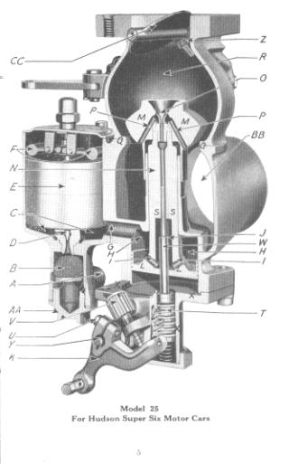
3 Carburetor The carburetor is a device for metering correct amounts of fuel and air for the various conditions of engine speed and load. To attain good carburetion it is necessary that the fuel supply be properly atomized and thoroughly mixed with the air. The Hudson-Essex carburetor has a float chamber of conventional design, which is connected to a vacuum tank. The vacuum tank draws the fuel from the main tank by suction and it is fed to the carburetor by gravity. By means of a float and mechanism the level of fuel in the float chamber is automatically kept at a certain height or head. From this chamber the fuel passes into the main part of the carburetor, where it is metered, thoroughly atomized, and then mixed with the correct amount of air in what is known as the mixing chamber. From this point the mixture passes through a butterfly type of throttle valve, which in turn controls the volume delivered to the cylinders. Float Chamber Fuel enters the carburetor at A, passing up through the strainer B, into the float chamber C, through the needle valve D. The valve D is actuated by means of the float E, operating through the counterweight levers F. As the fuel flows into the float chamber the float rises and, acting against the levers F, forces the needle valve down and closes same. As the float rises the valve closes until the float reaches a certain predetermined level at which the valve is entirely closed. If the float falls below this level, because of the diminishing supply of fuel in the float chamber, the valve is automatically opened and more fuel is admitted to bring the level up to correct height. From the above it will be seen that the float chamber constitutes a reservoir of constant supply, in which the height of fuel is always at the same level. This contributes to efficient metering. 3
4 A Fuel Supply Connection B Strainer C Float Chamber D Gasoline Needle Valve E Float F Counterweight Levers G Gasoline Passage H Dashpot Chamber I Gasoline Passages J Gasoline Passage K Dash Adjustment Lever L Dashpot Piston M Metering Valve Head N Metering Valve Stem O Aspirating Tube or Nozzle P Primary Air Passages Q Metering Valve Seat R Mixing Chamber S Fuel Metering Orifice T Metering Pin Rack Carrier U Adjustment Lever Clamp Screw V Adjustment Screw W Metering Pin X Gear Housing Y Pinion Shaft Z Low Throttle Stop Screw AA Strainer Plug BB Air Inlet CC Throttle Valve 4
5
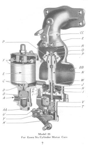
6 A Fuel Supply Connection B Strainer C Float Chamber D Gasoline Needle Valve E Float F Counterweight Levers G Gasoline Passage H Dashpot Chamber I Gasoline Passages J Gasoline Passage K Dash Adjustment Lever L Dashpot Piston M Metering Valve Head N Metering Valve Stem O Aspirating Tube or Nozzle P Primary Air Passages Q Metering Valve Seat R Mixing Chamber S Fuel Metering Orifice T Metering I'in Rack Carrier U Adjustment Lever Clamp Screw V Adjustment Screw W Metering Pin X Gear Housing Y Pinion Shaft Z Low Throttle Stop Screw AA Strainer Plug BB Air Inlet CC Throttle Valve 6
7
8 Dashpot Chamber From the float chamber the fuel flows through passage G into the dashpot chamber H. It also passes through the holes I in the valve piston into the central space J which surrounds the tapered metering pin W. The metering valve has a piston L at its lower end and which operates in the dashpot chamber. The object of the dashpot is to improve the performance of the carburetor by steadying the action of the metering valve during acceleration and low speed operation of the engine. Metering Valve The metering valve consists of a conical shaped head M, stem N and piston L. This is the only moving part in the carburetor proper. It slides up and down in its guide, formed in the body of the carburetor. The upper part of this valve contains a jet or nozzle 0 and primary air openings P. When the engine is at rest the conical head of the metering valve seats in the carburetor body at Q. When the engine is running, however, the metering valve is always floating in some higher position, thereby forming an annular or ring-shaped air opening between the conical head and its seat Q. Action of Carburetor The action of the carburetor is as follows: The suction created by the downward stroke of the engine pistons draws air into the mixing chamber R through the primary air openings P. The same suction draws a fine spray of atomized fuel from the nozzle 0 into the mixing chamber. The air thus mixing with the fuel forms a combustible gas for the engine. As soon as the engine begins to rotate, the metering valve lifts sufficiently to allow the main air supply to pass into the mixing chamber between the conical head M and the seat Q. Fuel is metered in an annular shaped orifice near the center of the valve at S, passing between the valve and the tapered portion of the stationary metering pin W. As the metering valve lifts into the higher positions, it gives increasingly larger fuel openings due to the 8
9 lifting of the valve away from the tapered metering pin, also larger air openings due to the lifting of the head of the metering valve M away from its seat Q. The metering valve measures the fuel at its lower end and the air at its upper end, the two being mixed in the chamber R. In other words, the metering valve under all conditions of operation automatically measures and delivers to the mixing chamber the most efficient proportions of fuel and air. The high velocity of primary or initial air passing through the holes P and around the nozzle 0 insures thorough breaking up or atomization of the fuel at all speeds. Carburetor Adjustments DO NOT TAMPER WITH THE CARBURETOR. The Hudson- Essex carburetor is exceedingly simple, there being only one point where any change in adjustment is possible. This adjustment is properly made at the factory when the carburetor is installed on the car and no change should be made unless it is positively known that the adjustment is incorrect. Very often, symptoms of carburetor trouble, such as mis-firing, backfiring, lack of power, overheating, etc., are produced by causes foreign to the carburetor. Therefore, before attempting any change in the carburetor adjustment, make sure that the compression is good and equal in all cylinders, that there are no air leaks between the carburetor and engine, that the ignition is timed correctly and delivering a hot spark, and also make sure that the spark plugs are clean and otherwise in good condition with gaps correctly set. It should be known that the fuel supply to the carburetor is sufficient and unrestricted. The only change of adjustment possible in the Hudson-Essex carburetor is that of the relative height of the tapered metering pin W to the opening in the center of the valve at S. The metering pin is carried by a circular rack T meshing with a pinion shaft Y to which is attached the dash adjustment lever K. By turning the adjustment screw V, the fixed or running position of the metering pin is changed. Turning the screw to the right (clockwise) lowers the metering pin, thereby increasing the fuel opening, and thus makes the 9
10 mixture richer. Turning the screw to the left (anti-clockwise) raises the metering pin and makes the mixture leaner. To obtain the best adjustment, first run the engine a sufficient length of time to get the jacket water up to normal running temperature. In this connection, the engine should not be too hot, as the adjustment thus obtained will likely be too lean for road conditions. With normal jacket water temperature, make the adjustment with the engine running idle, having the spark fully retarded and the low throttle stop screw Z (located at the top of the carburetor) so adjusted as to give an idling speed of approximately 250 R. P. M. Gradually turn the adjustment screw V to the left, thereby making the mixture leaner, until a point is reached where the engine runs unsteadily or stalls, when the adjustment should be reversed; that is, turned to the right, making the mixture richer a notch at a time until a point is reached where the engine will fire evenly. It is most important that the adjustment be made at idling speed with fully retarded spark. This one adjustment, when properly made, automatically insures correct carburetion throughout the entire range of car operating conditions. Dash Control For starting and warming up, the Iludson-Essex carburetor enriches the mixture by means of the dash control, which pulls down the tapered metering pin, thereby increasing the size of the fuel orifice. The air supply is in no way restricted. This means that the mixture can be made sufficiently rich for prompt, efficient starting and warming up in cold weather without flooding the engine with excessive quantities of raw fuel as with the use of an air strangle or choke valve. When starting the engine cold the dash control should be pulled all the way out but should be immediately returned part way as soon as the engine begins to fire. The amount which the control will have to be left out for warming up depends upon the weather conditions. During summer weather a slight amount is sufficient, whereas during extremely cold weather it may be necessary to leave control out as much as half way 10
11 the control out as much as half way for part of the warming-up period. A general rule for the amount which the mixture should be enriched by means of the dash control for warming up is to have the control out as little as possible and still obtain satisfaction acceleration. As soon as the engine comes to normal running temperature, the control should be pushed all the way in. If this is not done, considerable fuel will be wasted. Carburetion During Cold Weather Good starting can be obtained under extreme cold weather conditions as follows: Advance the spark nearly to the running position and set the throttle lever on the steering column so that it opens only slightly. In other words, the throttle should be opened just a little beyond the idling position. The dash control should be pulled all the way out while the engine is being cranked. When the engine commences to fire, the dash control should be left way out and the throttle lever should also be left as for starting, permitting the engine to run for eight or ten seconds. This will allow the combustion chamber walls to become somewhat heated, when the control can be pushed part way in and the engine accelerated as may be required. The above applies only when starting in extremely cold weather. Under ordinary weather conditions the dash control should be returned part way in immediately or as soon as the engine fires. Locating Adjustment Arm on Pinion Shaft As explained before, rotation of the pinion shaft moves the metering pin up or down, thus making the mixture leaner or richer. Motion of the dash control is transferred to the pinion shaft through the adjustment arm K. Ordinarily, a sufficient range of adjustment can be obtained by means of the screw V. In the event, however, that it should be found, upon adjusting the carburetor, that the mixture cannot be mad sufficiently lean when the screw V is turned all the way to the left, or sufficiently rich 11
12 when turned all the way to the right, this can be taken care of by shifting the adjustment arm K relative to the pinion shaft, to which it is clamped. To make this adjustment, first disconnect the adjustment arm spring and then loosen the adjustment arm clamp screw U. In case the mixture cannot be made lean enough by turning the screw V all the way to the left, the adjustment arm should be shifted one notch, or serration, to the right. In case the mixture cannot be made sufficiently rich when the adjustment screw V is turned all the way to the right, the adjustment arm should be shifted one notch to the left. To prevent the pinion shaft from rotating when the arm is removed, and thus losing the adjustment entirely, it is desirable to either remove the cap from the lower part of the gear housing and take out the small spring beneath the metering pin, or tighten the packing gland which surrounds the pinion shaft sufficiently so as to create enough friction to prevent the pinion rack spring from moving the pinion shaft. After shifting the adjustment arm, the clamp screw should be tightened and the spring connected, and the final adjustment made in the regular manner by means of the adjustment screw V. It is well to so locate the adjustment arm relative to the pinion shaft that when the carburetor is finally adjusted for running conditions the adjustment screw V will be approximately in the center of its travel, which will permit making the mixture either leaner or richer to suit seasonal changes. In case the location of the adjustment arm is completely lost, this can be restored, so that no difficulty will be encountered in starting the engine, by the following means: Detach the carburetor from the engine and then remove the throttle body, or upper part, by unscrewing the two cap screws. This will expose the metering valve head. Then, with the adjustment arm spring disconnected, also the clamp screw U loosened, the pinion shaft should be turned to the left (using the adjustment arm K as a wrench) so that the metering pin will be forced up into the metering valve, lifting same from its seat. Next, turn the pinion shaft in the opposite direction very slowly until the metering valve just touches its seat. Measurement should then 12
13 be taken of the distance between the end of the gear housing X (with the cap removed) and the rack T which carries the metering pin and slides within the gear housing. This can be done with a narrow scale or depth gauge. Next turn the pinion shaft to the right which will force the metering pin rack down 1/16 of an inch. This distance can be measured with the scale or depth gauge. Then carefully remove the adjust ment arm from the shaft, without turning same, and replace (again being careful not to turn the shaft) in such a position that the adjustment arm will come opposite the point of the adjustment screw when same is turned down approximately one-half of its total travel. Next the clamp screw should be tightened and the adjustment arm spring connected. This will give an approximate adjustment so that the engine can be easily started, and after bringing up to normal temperature, the final setting should be made by means of the screw V. Flooding of Carburetor Flooding or overflowing of the carburetor may result from one of several causes, such as leaky float or failure of the needle valve to seat because of dirt or other foreign matter. A leaky float is easily determined by shaking it near the ear. It should, of course, contain no fuel. In case the fuel supply contains foreign matter, this may become lodged between the point of the needle and its seat, causing the carburetor to flood. In this connection it is well to remove, from time to time, the strainer AA located at the lower part of the carburetor, and thoroughly clean it of any dirt or sediment. Should flooding be due to improper seating of the needle valve, this can sometimes be corrected by removing the cap from the center of the float chamber, which will expose the needle valve stem, and which can then be tapped lightly with the wooden handle of a small screw-driver, turning the needle in several different positions while tapping. 13
14 Carburetor Fouled With Dirt or Foreign Matter No amount of dirt contained in the air supply can possibly interfere with the action of the Hudson-Es sex carburetor. As in any other type of carburetor, however, if dirt, scale, or other foreign mat ter works through the strainer, it may cause trouble. To correct this the instrument can be easily disassembled by any competent mechanic and thoroughly cleaned. In order to accomplish this, the carburetor should first be removed from the engine and the outside thoroughly cleaned with gasoline or kerosene, so that the dirt will not work into the inside when the instrument is disassembled. Next remove the float chamber cover and float; unscrew the strainer plug at the bottom of the float chamber; remove the throttle body or upper part, by means of two cap screws which attach it to the main carburetor body, and also remove the gear housing assembly (that is, the lowest part of the carburetor) by means of the four screws which attach it to the main body. This will expose the principal working parts of the carburetor. If desired, the metering valve (M N L) can be disassembled by catching the head M in a vise or holding same with a wrench and turning the piston L to the left by means of a special dowel wrench, which fits into two holes drilled in the lower face of the piston. The head is attached to the stem by means of a right-hand thread. The carburetor body and disassembled parts should next be thoroughly washed with gasoline and blown out with compressed air, if this is available. The metering pin, also component parts of the metering valve, are very accurately machined and, when cleaning, no abrasives, such as files, emery cloth or sand paper, should be used. It is only necessary to clean these parts to have them function properly. In reassembling, take particular pains to note that the metering valve is entirely free to slide up and down in the body of the carburetor in any position to which it may be rotated. In the case of a carburetor which has been in service for some little time and is being disassembled for cleaning, it may be advisable to install new gaskets at the strainer connection, the 14
15 throttle body connection, and the gear housing. It is also desirable to tighten slightly the packing gland which surrounds the pinion shaft. This is accomplished by first loosening the lock nut and then tightening the packing nut, which has a right-hand thread. This, however, should never be so tight as to prevent the adjustment arm spring from re-turning the arm to the point of the screw. It is not necessary to remove the adjustment arm from the pinion shaft, thereby changing the adjustment of the carburetor, when the instrument is being disassembled for cleaning. Do Not Alter the Specifications of Carburetor The weight of the metering valve, size of jet, taper of metering pin and various clearances of the metering valve in the body, etc., have been very carefully worked out to suit the requirements of Hudson and Essex engines. None of these details should be in any way altered, as satisfactory results cannot be obtained if this is done. 15
CARTER DOWNDRAFT CARBURETOR Terraplane All Models. Technical Information
 CARTER DOWNDRAFT CARBURETOR 1934 Terraplane All Models Technical Information . Carter W-1 Downdraft Carburetors 1934 Terraplane Challenger, Model KS NOTE: Terraplane Models. Carburetor fitted with Anti-
TILLOTSON LTD., CLASH INDUSTRIAL ESTATE, TRALEE, CO. KERRY, IRELAND PHONE: FAX:
 TILLOTSON LTD., CLASH INDUSTRIAL ESTATE, TRALEE, CO. KERRY, IRELAND PHONE: +353 66 7121911 FAX: +353 66 7124503 e-mail: sales@tillotson.ie SERIES SERVICE MANUAL INTRODUCTION The gasoline engine industry
AN EXPLANATION OF CIRCUITS CARTER YH HORIZONTAL CLIMATIC CONTROL CARBURETER
 AN EXPLANATION OF CIRCUITS CARTER YH HORIZONTAL CLIMATIC CONTROL CARBURETER The Carter Model YH carbureter may be compared with a Carter YF downdraft carbureter with the circuits rearranged to operate
THE CARBURETOR: THE ADDITIONAL SYSTEMS
 THE CARBURETOR: THE ADDITIONAL SYSTEMS From the acceleration pump to the power jet: the special configuration of circuits that apply to some carburetor models As stated in the previous article, a carburetor
TILLOTSON LTD., CLASH INDUSTRIAL ESTATE, TRALEE, CO. KERRY, IRELAND PHONE: FAX:
 TILLOTSON LTD., CLASH INDUSTRIAL ESTATE, TRALEE, CO. KERRY, IRELAND PHONE: +353 66 7121911 FAX: +353 66 7124503 e-mail: sales@tillotson.ie HS SERIES SERVICE MANUAL INTRODUCTION The demand for a miniature
12. CARBURETOR/FUEL PUMP
 12 CARBURETOR/FUEL PUMP SERVICE INFORMATION... 12-2 TROUBLESHOOTING... 12-2 THROTTLE VALVE DISASSEMBLY... 12-3 THROTTLE VALVE INSTALLATION... 12-4 CARBURETOR REMOVAL... 12-5 AUTO BYSTARTER... 12-6 FLOAT
TILLOTSON LTD., CLASH INDUSTRIAL ESTATE, TRALEE, CO. KERRY, IRELAND PHONE: FAX:
 TILLOTSON LTD., CLASH INDUSTRIAL ESTATE, TRALEE, CO. KERRY, IRELAND PHONE: +353 66 7121911 FAX: +353 66 7124503 e-mail: sales@tillotson.ie HU SERIES SERVICE MANUAL INTRODUCTION To keep apace of new market
5. FUEL SYSTEM 5-0 FUEL SYSTEM UXV 500
 5 FUEL SYSTEM 5 SERVICE INFORMATION------------------------------------------------ 5-02 TROUBLESHOOTING----------------------------------------------------- 5-03 FUEL TANK -----------------------------------------------------------------
FUEL SYSTEM. Table of Contents. Specifications. Section 3A Fuel Delivery System. Models 6/8/9.9/10/15 CARBURETOR SPECIFICATIONS
 FUEL SYSTEM Section 3A Fuel Delivery System Table of Contents Specifications............................. 3A-1 WMC Carburetor Specifications............. 3A-2 WMC Carburetor Specifications.............
5. FUEL SYSTEM 5-0 FUEL SYSTEM MXU 250R/300R
 5 FUEL SYSTEM 5 SERVICE INFORMATION------------------------------------------------ 5-2 TROUBLESHOOTING----------------------------------------------------- 5-3 FUEL TANK -----------------------------------------------------------------
HUDSON MOTOR CAR COMPANY
 HUDSON MOTOR CAR COMPANY 1935-1942 Carburetor Tune-up Manual ( for Hudson and Terraplane Models) Index Carter W-1 Downdraft 1935-1942 1 Carter W-1 Vacumeter Type 1938 Hudson 4 Carter WA-1 Vacumeter Type
Automobile section, showing different parts in detail. and miscellaneous devices.
 SECTION VII Nos. 97 112 Automobile section, showing different parts in detail. and miscellaneous devices. Hydraulic jack MECHANICAL MODELS 43 Section VII 97. Automobile engine starter. This device known
4. FUEL SYSTEM CK 1 4-0
 4 4 4-0 SERVICE INFORMATION... 4-1 FLOAT LEVEL INSPECTION... 4-5 TROUBLESHOOTING... 4-2 CARBURETOR INSTALLATION... 4-6 THROTTLE VALVE DISASSEMBLY... 4-3 THROTTLE VALVE ASSEMBLY... 4-6 CARBURETOR REMOVAL...
FUEL SYSTEM/CARBURETOR/FUEL PUMP
 13 FUEL SYSTEM/CARBURETOR/FUEL PUMP FUEL SYSTEM-------------------------------------------------------------------------------------13-1 SCHEMATIC DRAWING-------------------------------------------------------------------------13-2
12. CARBURETOR 12-0 CARBURETOR VITALITY 50
 12 12 CARBURETOR SERVICE INFORMATION (2-STROKE)... 12-2 SERVICE INFORMATION (4-STROKE)... 12-3 THROTTLE VALVE (2-STROKE)... 12-5 CARBURETOR (2-STROKE)... 12-7 AIR SCREW ADJUSTMENT (2-STROKE)... 12-13 REED
CARBURETOR SERVICE INFORMATION TROUBLESHOOTING THROTTLE VALVE DISASSEMBLY THROTTLE VALVE INSTALLATION...
 11 CARBURETOR SERVICE INFORMATION... 11-2 TROUBLESHOOTING... 11-2 THROTTLE VALVE DISASSEMBLY... 11-3 THROTTLE VALVE INSTALLATION... 11-4 CARBURETOR REMOVAL... 11-5 AUTO BYSTARTER... 11-6 FLOAT CHAMBER...
GENERAL DESCRIPTION ROCHESTER 4GC 4-JET CARBURETOR 6B PONTIAC SHOP MANUAL
 6B-56 1955 PONTIAC SHOP MANUAL GENERAL DESCRIPTION ROCHESTER 4GC 4-JET CARBURETOR The Rochester 4GC Carburetor for the 1955 Pontiac V -8 is essentially two 2 -J et carburetors in a single casting. The
THE IDLE CIRCUIT AND THE PROGRESSION. We have seen how in a "basic"
 THE IDLE CIRCUIT AND THE PROGRESSION Manufacture and operation of two very important systems, which allow the practical use of a carburetor for motorcycles We have seen how in a "basic" (simplified) carburetor,
Sales : Mobile : The Zenith 24 T-2 carburettor
 The Zenith 24 T-2 carburettor is an up draught carburettor, developed principally for use on your Ferguson TEA20 (Vaaljapie) tractor. It can be supplied in several versions, the main variations being the
5. FUEL SYSTEM FUEL SYSTEM 5-0
 5 FUEL SYSTEM 5-0 SERVICE INFORMATION GENERAL INSTRUCTIONS SERVICE INFORMATION...5-1 CARBURETOR INSTALLATION...5-9 TROUBLESHOOTING...5-1 PILOT SCREW ADJUSTMENT...5-10 CARBURETOR REMOVAL...5-2 AUTO BYSTARTER...5-3
4. FUEL SYSTEM 4-0 FUEL SYSTEM NEXXON 50
 4 FUEL SYSTEM SERVICE INFORMATION ------------------------------------------------ 4-2 TROUBLESHOOTING----------------------------------------------------- 4-3 AIR CLEANER REMOVAL -----------------------------------------------
Typical Install Instructions
 Typical Install Instructions Read & understand all steps of these instructions before beginning this installation. WEBER Conversion Kit, VW T-1/2, up to 1835cc 32 / 36 DFEV Weber Carburetor These instructions
INSIDE YOUR HOLLEY CARBURETOR FUEL INLET SYSTEM
 INSIDE YOUR HOLLEY CARBURETOR The carburetor is quite simply a fuel metering device that operates under the logical and straightforward laws of physics. It has evolved over the years from a very simple
13. FUEL SYSTEM/CARBURETOR/
 13 FUEL SYSTEM/CARBURETOR/FUEL PUMP FUEL SYSTEM --------------------------------------------------------- 13-1 SCHEMATIC DRAWING ---------------------------------------------- 13-2 OPERATION OF CARBURETOR
A-PDF Split DEMO : Purchase from to remove the watermark
 5-18 FUEL AND LUBRICATION SYSTEM A-PDF Split DEMO : Purchase from www.a-pdf.com to remove the watermark Use a % size drill bit with a drill-stop to remove the pilot screw plug. Set the drill-stop 6 mm
11. CARBURETOR 11-0 CARBURETOR ZX / SCOUT 50
 11 CARBURETOR SERVICE INFORMATION... 11-2 TROUBLESHOOTING... 11-2 THROTTLE VALVE DISASSEMBLY... 11-3 THROTTLE VALVE INSTALLATION... 11-4 CARBURETOR REMOVAL... 11-5 AUTO BYSTARTER... 11-6 FLOAT CHAMBER...
7. FUEL SYSTEM ('04 - '05)
") 7. FUEL SYSTEM ('04 - '05) SYSTEM COMPONENTS 7-2 CARBURETOR DISASSEMBLY 7-81 SERVICE INFORMATION 7-3 CARBURETOR ASSEMBLY 7-14 TROUBLESHOOTING 7-4 CARBURETOR INSTALLATION 7-21 AIR CLEANER HOUSING 7-5 PILOT
7. FUEL SYSTEM ('04 - '05) SYSTEM COMPONENTS 7-2 CARBURETOR DISASSEMBLY 7-81 SERVICE INFORMATION 7-3 CARBURETOR ASSEMBLY 7-14 TROUBLESHOOTING 7-4 CARBURETOR INSTALLATION 7-21 AIR CLEANER HOUSING 7-5 PILOT
TILLOTSON LTD., CLASH INDUSTRIAL ESTATE, TRALEE, CO. KERRY, IRELAND PHONE: FAX:
 TILLOTSON LTD., CLASH INDUSTRIAL ESTATE, TRALEE, CO. KERRY, IRELAND PHONE: +353 66 7121911 FAX: +353 66 7124503 e-mail: sales@tillotson.ie HR SERIES SERVICE MANUAL INTRODUCTION Tillotson has developed
I.C Engine Topic: Fuel supply systems Part-1
 I.C Engine Topic: Fuel supply systems Part-1 By: Prof.Kunalsinh Kathia Essential parts of carburetor Fuel strainer Float chamber Metering and idiling system Choke and throttle Fuel strainer As gasoline
2) Rich mixture: A mixture which contains less air than the stoichiometric requirement is called a rich mixture (ex. A/F ratio: 12:1, 10:1 etc.
 Rich mixture: A mixture which contains less air than the stoichiometric requirement is called a rich mixture (ex. A/F ratio: 12:1, 10:1 etc.") Unit 3. Carburettor University Questions: 1. Describe with suitable sketches : Main metering system and Idling system 2. Draw the neat sketch of a simple carburettor and explain its working. What are the
Unit 3. Carburettor University Questions: 1. Describe with suitable sketches : Main metering system and Idling system 2. Draw the neat sketch of a simple carburettor and explain its working. What are the
TECH INFORMATION EMPI D Performance 2-Barrel Carburetor
 TECH INFORMATION EMPI D Performance 2-Barrel Carburetor The New EMPI D 2-Barrel Performance Carburetor.Built specifically for the VW Aftermarket. With all the features that you have asked for More Progression
Tillotson Tc3A Carburator
 Tillotson Tc3A Carburator 176 FUEL SYSTEMS - 5B-11 CENTER BOWL TYPE CARBURETOR Removal 1. Remove front cowl cover and wrap-around cowl. 2. Remove swivel link from lower carburetor. (Figure 2) 3. Loosen
03. Fuel and Air Feed System
 Page 11 of 03. Fuel and Air Feed System Content (16 Marks) 3.1 Petrol fuel supply system. 8 Marks Conventional Petrol Engine: Gravity feed, Pump feed (Layout,Function of Components and location). Construction
FUEL AND LUBRICATION SYSTEM
 AND LUBRICATION SYSTEM 4-1 A-PDF Split DEMO : Purchase from www.a-pdf.com to remove the watermark AND LUBRICATION SYSTEM CONTENTS SYSTEM... 4-2 PUMP... 4-2 TANK/ COCK... 4-3 REMOVAL... 4-3 INSPECTION...
CARBURETION. Flo-Jet Carburetors. One Piece. One-Piece Flo-Jet. Main Jet Adjustment N eedle
 One Piece One-Piece Flo-Jet The small One-Piece Flo-Jet carburetor is illustrated in Fig. 122 and was used on early Model 170700. These are float feed carburetors with adjustable orifice main jet needle
2007 HOP-UP INFORMATION. Foreword
 2007 HOP-UP INFORMTION Foreword This manual contains the hop-up information for RM series of European specification and is intended to allow the standard model to achieve its maximum performance potential.
HE Stewart Vacuum Gasoline System employs a small tank, installed under the hood. This tank is connected by brass tubing to the intake manifold, also
 T HE Stewart Vacuum Gasoline System employs a small tank, installed under the hood. This tank is connected by brass tubing to the intake manifold, also to gasoline supply tank, and to carburetor. Every
Maintenance Information
 16572679 Edition 2 May 2014 Air Drill QP Series Maintenance Information Save These Instructions Product Safety Information WARNING Failure to observe the following warnings, and to avoid these potentially
PIERBURG. Carburetor: 2E3
 PIERBURG Carburetor: 2E3 1 fast idle adjusting screw 2 throttle lever 3 fuel mixture adjusting screw 4 main body 5 idle cut off valve 6 stop screw 7 accelerator pump cover 8 diaphragm 9 spring 10 valve
DESCRIPTION FUEL AND VACUUM PUMP REMOVE AND REPLACE FUEL PUMP-OVERHAUL 6B PONTIAC SHOP MANUAL. S. Install battery and connect cables.
 6B-74 1955 PONTIAC SHOP MANUAL DESCRIPTION FUEL AND VACUUM PUMP All models are equipped with a combination fueland double acting vacuum pump operated by an eccentric bolted to the front end of the engine
Урал) - Dnepr (Днепр) Russian Motorcycle Carburetors
 - Dnepr (Днепр) Russian Motorcycle Carburetors") Ural (Урал( Урал) - Dnepr (Днепр) Russian Motorcycle Carburetors Part 8A: Adjustment and Overhaul of the Pekar K-65 Carburetors (see also Part 8-8 K-65 Carburetor and Part 8B- Setting Up K-65 K Carbs)
Ural (Урал( Урал) - Dnepr (Днепр) Russian Motorcycle Carburetors Part 8A: Adjustment and Overhaul of the Pekar K-65 Carburetors (see also Part 8-8 K-65 Carburetor and Part 8B- Setting Up K-65 K Carbs)
Hudson-Essex. Service Manual Supplement. Hudson Cars 750,001 up
 1 9 2 6 Hudson-Essex Service Manual 1927 Supplement Hudson Cars 750,001 up Hudson Rear Axle (Cars numbered 750,001 and upward) Brakes (Cars numbered 750,001 and upward) See page 18 Transmission Group
BASIC INSTRUCTIONS SHIFTER KZ1 / KZ2 e X30 SHIFTER-TaG
 BASIC INSTRUCTIONS SHIFTER KZ1 / KZ2 e X30 SHIFTER-TaG FEEDING: by fuel mixture 98NO (min. 95NO) and 4% oil (CIK homologated). ATTENTION: the engine is supplied without oil in the gearbox. GEARBOX OIL
AUTOMATIC CLUTCH Models
 AUTOMATIC CLUTCH 1940 Models Source of this material is from 1940 Series, Issue 4, January 1940 Hudson Service Magazine AUTOMATIC CLUTCH 1940 MODELS The automatic clutch installation and adjustment procedure
QUICK FUEL TECHNOLOGY HOT ROD SERIES CARBURETORS SLAYER SERIES CARBURETORS SUPER STREET SERIES CARBURETORS
 QUICK FUEL TECHNOLOGY Installation Instructions HOT ROD SERIES CARBURETORS SLAYER SERIES CARBURETORS SUPER STREET SERIES CARBURETORS HR-580-VS 580 CFM Vac. Secondary!!! SS-680-VS 680 CFM Vac. Secondary
MODELS 3100,3130,3160, 1300, 1330,1360 EXHAUST SYSTEM
 MODELS 3100,3130,3160, 1300, 1330,1360 EXHAUST SYSTEM WALBRO CARBURETOR "WA" SERIES MUFFLER REMOVAL CARBURETOR REMOVAL The muffler assembly should beremoved periodically to inspect for excessive carbon
~. a~' ~ ( I o~~~ 4-0. ~Sj~' AO~ i/~ CB1000C (ij)aon'da in-ib) ~ "" ~ ~!~~P. ~ J N m (6-12 kg-em,
aon'da in-ib) ~ ~ ~!~~P. ~ J N m (6-12 kg-em,") e V ~. a~' ~ I ~ J C t \"" 8.0- ( I o~~~ ~ "" ~ ~. ~!~~P. C8 0 & 0,-t. ~ CB1000C (ij)aon'da 0.6-1.2 N m (6-12 kg-em, 5-10 in-ib) 4-0 / 4.0-6.0 N m (40-60 kg-em, 35-52 in-i b) t$ "'07~ / c;:::/ j ~Sj~'
e V ~. a~' ~ I ~ J C t \"" 8.0- ( I o~~~ ~ "" ~ ~. ~!~~P. C8 0 & 0,-t. ~ CB1000C (ij)aon'da 0.6-1.2 N m (6-12 kg-em, 5-10 in-ib) 4-0 / 4.0-6.0 N m (40-60 kg-em, 35-52 in-i b) t$ "'07~ / c;:::/ j ~Sj~'
WEBER CARBURETOR TROUBLESHOOTING GUIDE
 This guide is to help pinpoint problems by diagnosing engine symptoms associated with specific vehicle operating conditions. The chart will guide you step by step to help correct these problems. For successful
Types of Carburetors. How they work. This presentation is from Virginia Tech and has not been edited by the Georgia Curriculum Office.
 Types of Carburetors How they work This presentation is from Virginia Tech and has not been edited by the Georgia Curriculum Office. Performance Objectives Students will be able to list and describe the
Performer Series Carburetor Rebuild Kit Catalog #1477 Models
 Please read these instructions carefully before attempting to rebuild your carburetor. Make sure to refer to your carburetor Owner s Manual for further information if need be. If you have any questions
SECTION 4 - FUEL/LUBRICATION/COOLING
 For Arctic Cat Discount Parts Call 606-678-9623 or 606-561-4983 SECTION 4 - FUEL/LUBRICATION/COOLING 4 TABLE OF CONTENTS Carburetor Specifications... 4-2 Carburetor Schematic... 4-2 Carburetor... 4-3 Cleaning
Use these modules to gain valuable knowledge about STIHL policies, procedures and products that will be a benefit to you on the job immediately.
 Bronze Level Training Lesson 09 This is Bronze Level 09 of 10. Welcome to the Service Advantage Bronze Level Training on icademy. These modules are designed to enhance your knowledge base on topics such
Tuning A Walbro Carb. Walbro Carb TUNE UP & Illustrated Guide
 Tuning A Walbro Carb Walbro Carb TUNE UP & Illustrated Guide by M. B. Fuess Walbro carbs aren t too difficult to tune up if you know what you re doing. First of all, you need to know how the carb works
Instruction Model 18537
 Instruction 738-556 Model 18537 LIMITED WARRANTY H. D. Hudson Manufacturing Company warrants to the original purchaser only that this product will continue to function as intended if used in accordance
"F" SERIES (Cont.) AIR FILTER ASSEMBLY NOTE NOTE. To remove grasp the cover, loosen snap and. If engine is flooded, fuel can drain back into
 AIR FILTER ASSEMBLY NOTE NOTE. To remove grasp the cover, loosen snap and. If engine is flooded, fuel can drain back into") CARB.-AIR-FILTER ASSEMBLY GASKET RETAINER PASSAGE AIR FILTER ASSEMBLY AIR FILTER If engine is flooded, fuel can drain back into filter. As filter becomes saturated, incoming air picks up more fuel, causing
CARB.-AIR-FILTER ASSEMBLY GASKET RETAINER PASSAGE AIR FILTER ASSEMBLY AIR FILTER If engine is flooded, fuel can drain back into filter. As filter becomes saturated, incoming air picks up more fuel, causing
Vacuum Readings for Tuning and Diagnosis
 Vacuum Readings for Tuning and Diagnosis -Henry P. Olsen Once you learn to properly interpret its readings, a vacuum gauge can be one of the most useful tools in your toolbox. 22 FEATURE Some people consider
Body type location. Model number location. Small Engine Parts
 Body type location Model number location Small Engine Parts FUEL PUMP SYSTEM SYSTEMS AND OPERATION The fuel pump on a diaphragm carburetor uses the vacuum and pressure pulse from the engines crankcase
ZAMA CUBE CARBURETOR DISASSEMBLY AND SERVICE
 ZAMA CUBE CARBURETOR DISASSEMBLY AND SERVICE MIXTURE SCREWS Remove idle and main mix ture screw. Inspect each screw for damage, especially the needle points which should have no deformation of the tapered
Rebuild and Adjustment Manual for Models 2010, 2300, 4010, 4011, 4150, 4160, 4165, 4175, and 4500
 Rebuild and Adjustment Manual for Models 2010, 2300, 4010, 4011, 4150, 4160, 4165, 4175, and 4500 WARNING! These instructions must be read and fully understood before beginning installation. Failure to
TECHNICAL DATA. COMPRESSION RATUI 9,5/1 WEIGHT ready to fly CONSUMPTION at 5400RPM 5,6litres/h POWER at 6200RPM
 VICTOR 1 SUPER This handbook aims to bring to the attention of key technical, functional and maintenance of your motor VICTOR 1. Read carefully the following pages, will be synonymous with safety, reliability
CH. 48 ENGINE MECHANICAL PROBLEMS TEST
 TERRY FOX AUTOMOTIVE CH. 48 ENGINE MECHANICAL PROBLEMS TEST WHEN YOU ARE DONE THIS TEST GUESS WHAT YOU THINK YOU WILL RECEIVE FOR A MARK BELOW. IF YOU ARE WITHIN 2 MARKS YOU WILL RECEIVE 2 BONUS MARKS.
RELEASING PRESSURE IN THE HYDRAULIC SYSTEM,
 Testing And Adjusting Introduction NOTE: For Specifications with illustrations, make reference to SPECIFICATIONS for 225 EXCAVATOR HYDRAULIC SYSTEM, Form No. SENR7734. If the Specifications are not the
JOB AID INTRODUCTION TOOLS REQUIRED: GC160 GC190 GS190 GCV160 GCV190 GSV160 GSV190 CARBURETOR CLEANING
 JOB AID GC160 GC190 GS190 GCV160 GCV190 GSV160 GSV190 CARBURETOR CLEANING INTRODUCTION Service engineering has discovered that many GCV carburetors returned for warranty were improperly cleaned. Eighty
Operating and Maintenance Manual for Type S Flowmeters. M101 Rev. B Type S Flowmeters: 5 8, 3 4 and 1 with 157 & 600 Series Registers
 Operating and Maintenance Manual for Type S Flowmeters M101 Rev. B Type S Flowmeters: 5 8, 3 4 and 1 with 157 & 600 Series Registers TABLE OF CONTENTS Installation & Operation... Page 1 Calibration...
Accident Prevention Program
 Accident Prevention Program Part I ENGINE OPERATION FOR PILOTS by Teledyne Continental Motors SAFE ENGINE OPERATION INCLUDES: Proper Pre-Flight Use the correct amount and grade of aviation gasoline. Never
SD Bendix E-10PR Retarder Control Brake Valve DESCRIPTION. OPERATION - Refer to Figure 2
 SD-03-832 Bendix E-10PR Retarder Control Brake Valve MOUNTING PLATE SUPPLY 4 PORTS ELECTRICAL AUXILIARY DESCRIPTION TREADLE RETARDER CONTROL SECTION EXHAUST DELIVERY 4 PORTS FIGURE 1 - E-10PR RETARDER
Water pump Owner's Manual
 Water pump Owner's Manual Safety Precautions I. General Safeguards Please read this operation manual to have a thorough understanding of the content there before use the product. Failure to do so may lead
Typical Fuel Systems - An Overview
 Typical Fuel Systems - An Overview Richard Skiba Skiba, R. (1999). Typical Fuel Systems An Overview, Pacific Flyer, March. Skiba, R. (2001). 'Typical Fuel Systems - An Overview'. Air Sport: The Home of
KEIHIN CARBURATORS FOR 4-CYLINDER HONDA MOTORCYCLES
 KEIHIN CARBURATORS FOR 4-CYLINDER HONDA MOTORCYCLES Set of 4 Keihin carburetors marked 089A and used on 1976 CB550K GENERAL NOTES: All carburetors perform the same function: mixing air and fuel for supply
BRAWLER SERIES CARBURETORS
 BRAWLER SERIES CARBURETORS Installation Instructions Please Stop and Read these Instructions before proceeding. If you do not fully understand the installation and tuning instructions you should seek professional
Pump Operating and Maintenance Manual - Models
 Pump Operating and Maintenance Manual - Models 78-00111 - 78-0057 Thank you for purchasing the SDI Diaphragm Pump manufactured by Comet Pump. Comet produces quality products which are safe, efficient and
HSR Carburetor Easy Kits Installation Instructions For Evo Big Twin Kit: # 42-7 Twin Cam Kit: # 42-18
 HSR Carburetor Easy Kits Installation Instructions For Evo Big Twin Kit: # 42-7 Twin Cam Kit: # 42-18 Revised 5/01/01 EK-1 Easy Kit Installation Instructions The HSR series carburetors are precise yet
TYPE E Main Valve Sizes 3 /8 through 12
 Technical Data SD 3001E PRINTED IN U.S.A. SD 3001E/9709 SPENCE ENGINEERING COMPANY, INC. 150 COLDENHAM ROAD, WALDEN, NY 12586-2035 A B TYPE E MAIN VALVE FACE TO FACE DIMENSIONS C D E DIMENSIONS (inches)
Internal Combustion Engines
 Internal Combustion Engines The internal combustion engine is an engine in which the burning of a fuel occurs in a confined space called a combustion chamber. This exothermic reaction of a fuel with an
Name Date. True-False. Multiple Choice
 Name Date True-False T F 1. Oil film thickness increases with an increase in oil temperature. T F 2. Displacement is the volume that a piston displaces in an engine when it travels from top dead center
FU-1 FUEL SYSTEM. Page PRECAUTIONS... TROUBLESHOOTING... ON-VEHICLE INSPECTION...
 FU-1 FUEL SYSTEM PRECAUTIONS... TROUBLESHOOTING... ON-VEHICLE INSPECTION... CARBURETOR FUEL PUMP... Page FU-2 FU-2 FU-3 FU-4 FU-28 FU-2 FUEL SYSTEM - Precautions, Troubleshooting PRECAUTIONS 1. Before
EDELBROCK PERFORMER SERIES EMISSIONS LEGAL CARBURETOR 600cfm, Electric Choke, EGR, Square-Bore Carburetor. Part #1400 INSTALLATION INSTRUCTIONS
 EDELBROCK PERFORMER SERIES EMISSIONS LEGAL CARBURETOR 600cfm, Electric Choke, EGR, Square-Bore Carburetor INSTALLATION INSTRUCTIONS PLEASE study these instructions carefully before beginning this installation.
This file is available for free download at
 This file is available for free download at http://www.iluvmyrx7.com This file is fully text-searchable select Edit and Find and type in what you re looking for. This file is intended more for online viewing
OWNER S MANUAL G620PU-1 MODEL: G620PU WARNING 848H4893A3 (704)
") 848H4893A3 (704) OWNER S MANUAL MODEL: G620PU G620PU-1 WARNING Do not modify any parts of the engine. This engine is designed to be used to Radio controlled products. In case any modification by customer,
848H4893A3 (704) OWNER S MANUAL MODEL: G620PU G620PU-1 WARNING Do not modify any parts of the engine. This engine is designed to be used to Radio controlled products. In case any modification by customer,
ACTUAL CYCLE. Actual engine cycle
 1 ACTUAL CYCLE Actual engine cycle Introduction 2 Ideal Gas Cycle (Air Standard Cycle) Idealized processes Idealize working Fluid Fuel-Air Cycle Idealized Processes Accurate Working Fluid Model Actual
Sherco Carb Jetting Instructions
 Sherco Carb Jetting Instructions This manual provides instructions on how to remove and reinstall the stock carburetor, it also shows you how to change the pilot jet and the main jet. It is intended to
Maintenance Information
 Form 16573321 Edition 1 July 2004 Air Grinder Series 61H Maintenance Information Save These Instructions Always wear eye protection when operating or performing maintenance on this tool. Always turn off
I & M 8000 Series. Ideal Installation Schematic. Preferred Installation. Trouble Shooting
 I & M 8000 Series 3170 Wasson Road Cincinnati, OH 45209 USA Phone 513-533-5600 Fax 513-871-0105 lowflow@richardsind.com www.lowflowvalve.com Installation & Maintenance Instructions for 8000 Series Low
Honda Accord/Prelude
 Honda Accord/Prelude 1984-1995 In Tank Fuel Pumps TEST 1. Turn the ignition OFF. 2. On the Accord, remove the screws securing the underdash fuse box to its mount. Remove the fuel cut off relay from the
California State University, Bakersfield. Signals and Systems. Kristin Koehler. California State University, Bakersfield Lecture 4 July 18 th, 2013
 Kristin Koehler California State University, Bakersfield Lecture 4 July 18 th, 2013 1 Outline Internal combustion engines 2 stroke combustion engines 4 stroke combustion engines Diesel engines 2 Consists
Service Instruction ENGINE COMPONENTS, INC.
 Title: Service Instruction S.I. No.: 89-5-1 Page: 1 of 5 Issued: 05/05/89 Revision: 1 (09/01/01) Technical Portions of FAA DER Approved. FAILURE OF ENGINE TO START 27 points 1. Lack of fuel 2. Ignition
CARBURETOR - HITACHI 2-BBL
 CARBURETOR - HITACHI 2-BBL 1986 Isuzu Trooper II 1986 Hitachi Carburetors HITACHI DCH340, DCR384, DFP340, DFP384 & DHP340 2-BARREL P UP & Trooper II DESCRIPTION Carburetor is a 2-barrel downdraft type
66 CHAPTER FOUR. Spark Plug Removal Refer to Figure 28 for spark plug wive routing according to engine.
 66 CHAPTER FOUR IGNITION SYSTEM A mechanical contact breaker point ignition system is used on all engines covered in this manual. The ignition system may use a Delco-Remy, Autolite, Mallory or Prestolite
Maintenance Information
 16575243 Edition 2 October 2013 Air Screwdrivers 1R Series Maintenance Information Save These Instructions Product Safety Information WARNING Failure to observe the following warnings, and to avoid these
SECTION 4 - FUEL SYSTEMS AND CARBURETION
 SECTION - FUEL SYSTEMS AND CARBURETION FUEL SYSTEMS - - - - - - - - - - - - - - - - - - - - - - - - - - - - - - - - - - - - - - - - - - - - - - - - - - - - - - - - - - - - - -62 FUEL PUMP - - - - - - -
February 26, ch.12.notebook. Ch. 12. Preventative Maintenance and Troubleshooting. Feb 23 5:03 PM
 Ch. 12 Preventative Maintenance and Troubleshooting Feb 23 5:03 PM 1 Why PM? preventive maintenance certain maintenance tasks must be performed regularly to keep an engine working properly helps premature
WARNING Carefully Read These Instructions Before Use
 DO NOT RETURN THIS SPRAYER TO STORE Call: 1-800-950-4458 Backpack Sprayer Use and Care Manual Manufactured for Northern Tool + Equipment Co., Inc. WARNING Carefully Read These Instructions Before Use Model
Maintenance Information
 16573321 Edition 3 February 2014 Air Grinder Series 61H Maintenance Information Save These Instructions Product Safety Information WARNING Failure to observe the following warnings, and to avoid these
SI unit. Supplementary unit unit. in Ib Ibf Ibfft psi qt(us) F. kg N Nm bar 1 C
 F. kg N Nm bar 1 C") SI unit mm kg N Nm bar 1 C Supplementary unit unit in Ib Ibf Ibfft psi qt(us) F Technical data Carburettor Carburettor type Single carburettor Plerburg Special tools 8393035 Adjusting toot, for metering
SI unit mm kg N Nm bar 1 C Supplementary unit unit in Ib Ibf Ibfft psi qt(us) F Technical data Carburettor Carburettor type Single carburettor Plerburg Special tools 8393035 Adjusting toot, for metering
OPERATING INSTRUCTIONS & SERVICE MANUAL BLUE MAX II HYDROSTATIC TEST PUMP
 PAGE 1 OF 10 OPERATING INSTRUCTIONS & SERVICE MANUAL BLUE MAX II HYDROSTATIC TEST PUMP EFFICIENT, EASY OPERATION Air operated pump Wide range of pressures and volumes Easy to operate controls Output pressure
Maintenance Information
 16573370 Edition 2 February 2014 Air Grinder 99V Series Maintenance Information Save These Instructions Product Safety Information WARNING Failure to observe the following warnings, and to avoid these
Holley High Performance Intake System* For Port 13B Engines (Includes B 6-Port engines converted to 4-Port)
") Holley High Performance Intake System* For 1974-1978 4-Port 13B Engines (Includes 1984-85 13B 6-Port engines converted to 4-Port) Installation Instructions I-18038 Note: These instructions assume: The
Holley High Performance Intake System* For 1974-1978 4-Port 13B Engines (Includes 1984-85 13B 6-Port engines converted to 4-Port) Installation Instructions I-18038 Note: These instructions assume: The
EDELBROCK THUNDER SERIES AVS CARBURETORS Part #1801, 1802, 1803, 1804, 1805, 1806, 1812, 1813, 1825, 1826 INSTALLATION INSTRUCTIONS
 EDELBROCK THUNDER SERIES AVS CARBURETORS Part #1801, 1802, 1803, 1804, 1805, 1806, 1812, 1813, 1825, 1826 INSTALLATION INSTRUCTIONS IMPORTANT NOTE: Proper installation is the responsibility of the installer.
Maintenance Information
 80234313 Edition 1 June 2006 Air Grinder, Die Grinder, Sander and Belt Sander Series G1 (Angle) Maintenance Information Save These Instructions WARNING Always wear eye protection when operating or performing
Handout Activity: HA170
 Basic diesel engine components Handout Activity: HA170 HA170-2 Basic diesel engine components Diesel engine parts are usually heavier or more rugged than those of similar output gasoline engines. Their