Instructions for SAITO FA-200R3 (AAC) 4-Stroke Engine
|
|
|
- Clyde Perkins
- 5 years ago
- Views:
Transcription


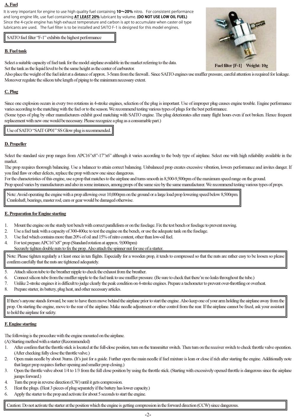
1 Instructions for SAITO FA-200R3 (AAC) 4-Stroke Engine We would like to express our sincere thanks for your purchase of the SAITO FA-200R3 engine. Please read our instructions carefully and treat your engine with care. If there re any manufacturing defects, SAITO Seisakusho co., ltd. will make necessary repairs free of charge. You are requested to strictly avoid disassembling the engine since assembled with the use of special tools and jigs to assure perfect construction. In the case of breakage or trouble, if encountered due to crash or others, please send the engine to our service station. Please notice that our guarantee will not cover any breakage or trouble on the engine caused by your disassembling or modification. Principal outside dimensions Explosion order (1-3-2) Prop rotational direction 1 Mechanism of 4-Stroke Engines The 4-Stroke engine provides 4 individual piston movements as illustrated below. The Stroke means the piston movement from the Top Dead Center to the Bottom Dead Center. In the 4-Stroke engine, one cycle of operation in change of gas state inside the cylinder and valve movement are completed at every 4 strokes of piston that is every 2 revolutions of the crankshaft. Formally the engine is called the 4-stroke one-cycle engine. 3 2 Cylinder numbers viewed from the rear Bore 27.0mm 3 Weight Approx. 1,385g (with mufflers) Propeller Standard APC16" 8"-10",17" 6" Stroke 19.2mm 3 Practical Speed 1,800-9,500rpm max range on the ground: 8,500-9,500rpm Stroke volume 32.98cc Static thrust Approx. 6-7kgf Fuel flow 46cc/min (At full throttle, Fuel of synthetic oil with 15% of nitro content, at approx 9,000rpm) *Fuel flow varies depends upon prop load. More fuel flow with larger load and less fuel flow with smaller load. Unique features of SAITO FA-200R3 Optimum for small-size scaled airplane Low vibration (assured by constant-interval explosion) Real sound of the exhaust. The engine is designed to equalize fuel mixture and minimize misfire due to insufficient distributing at idling by means of special port type intake manifold originally developed by SAITO. Cylinder head: Improved semi-spherical combustion chamber assures better combustion efficiency and volumetric efficiency. Cylinder: The aluminum cylinder is directly hard-chrome plated on its inner surface without installing liners to reduce weight and increase durability. The monolithic structure of cylinder head and cylinder prevents distortion and improves cooling efficiency. Piston: The piston is made of high silicon content aluminum and attached with a compression ring to heighten engine performance. Crankshaft: Has a forged solid construction made of chrome molybdenum steel, and supported by two ball bearings. Cam: Features high cam providing longer maximum lift time. Carburetor: High-performance of slow throttling type. Propeller nut: designed to have double nuts preventing loosening and fall-off for the safety. Standard Accessories 1. Wrench for tappet adjusting screw 1 pc. 5. Glow plug [SAI-GP01] 3 pcs. 2. Limit gauge (0.1t) for tappet adjusting 1 pc. (Attached to the engine) 3. Hexagonal wrench (1.5mm) 1 pc. 6. Plug heating connector set 1 set 4. Muffler complete 1 set (3pcs. of red cord, 1pc. of black, 2pcs. of fixture) -1-
2
3 (B) Manual starting method (For safety, wear gloves and use a safety stick) Same procedure as (A) describes. 3. Prime the engine. Open the throttle valve fully by using the throttle stick. Insert a proper length of silicone tube into the priming nipple. Use an injector to fill a proper amount (1-2cc) of fuel into the carburetor. 4. Manually crank the engine 2 to3 turns to supply fuel in cylinders. Then use the throttle stick to fully close the throttle valve. 5. Open the throttle valve about 1/4 to1/3 from the full close position by using the throttle stick. (Starting with excessively opened throttle is dangerous since the airplane jumps forward.) 6. Set the prop at the point of 30-45deg from the horizontal position, with the engine turned in forward direction (CCW) to the position to be compressed. Then heat the plugs. 7. Swiftly crank the engine in forward direction (CCW) to start the engine.. Priming Method G. Break-in As Break-in is an important procedure to pull out the maximum performance of the engine, it must be cautiously implemented. 1. After filling up the fuel tank, start the engine as described in the above section F. After starting the engine use the throttle stick to open the throttle valve to about half open. Adjust the main needle while observing tachometer, exhaust oil concentration and exhaust concentration from the breather, to run the engine at 5,000rpm or lower speed in rich condition for full tank fuel consumption. (Run the engine with plugs powered as required.) Caution: The purpose of break-in is initial adjusting of the master rod, link rod, bearings, gears and other mobile parts under the condition with rich fuel mixture. Never make the fuel mixture lean. Lean fuel mixture could cause seizure even if the engine drops to idling and runs at low speed. 2. Next adjust the main needle and throttle valve opening to run the engine in rich fuel condition at 7,000 8,000 rpm for full tank fuel consumption. (In this stage also observe tachometer reading, exhaust oil concentration and exhaust concentration from the breather.) 3. Next fully open the throttle valve and adjust the main needle to run the engine at approximately 9,000 rpm for full tank fuel consumption. 4. Finally adjust the main needle to run the engine at peak speed and less speed (richer) alternately. When the engine comes to run at a peak speed stably, ground break-in has been completed for the time being. Now adjust valve clearance by following procedure of maintenance described later. Then adjust carburetor according to the next article and make test flights at less speed around ten times to complete break-in. (Thereafter make flights at less speed, to prolong engine life.) Note: Rotary units and slide ways of the engine have been lubricated at assembly with black molybdenum oil to prevent wearing or seizure. Hence black exhaust oil comes out of the breather nipple and muffler at break-in operation. This could not be a trouble and you can continue the operation. H. Handling and Adjustment of Carburetor Note: Strictly avoid changing the direction of carburetor installation. Failure to do this will cause engine malfunction. The SAITO carburetor has been adjusted on its slow needle to our reference value at factory default. The slow needle requires some correction depending on various factors including the installation position, types of prop/fuel/plug, or climate conditions. Readjust the slow needle referring to the figure shown below. [Reference value (only for a guide)] Main needle: Open the needle by 2 turns from the full close point. Slow needle: Fully close the throttle valve and slow needle CW to the end. Then open the slow needle by about 3 turns from the full close point. 1. After filling up the fuel tank, start the engine as described in the previous section F. 2. Fully open the throttle valve. Adjust the main needle while observing tachometer, exhaust noise and exhaust smoke, to attain the speed peak. Caution: Excessive closing of main needle could cause knocking and give damage onto the engine. In such occasion, immediately turn the main needle CCW to make fuel mixture rich. 3. Next control the throttle stick to gradually close the throttle valve to run the engine stably in the range of around 2,000-2,500rpm. (Adjust the throttle stick while observing tachometer. Exhaust smoke concentration, or exhaust/intake noise.) a. Rich fuel mixture: Turn the slow needle CW to make fuel mixture leaner. b. Lean fuel mixture: Turn the slow needle CCW to make fuel mixture richer. 4. Once idling speed is set, fully open the throttle valve slowly. If the speed becomes irregular or suddenly increases on the way, carefully adjust the slow needle so that the engine speed changes linearly from the idling to the peak speed. 5. When the above adjustment is completed, quickly change the speed from idling to the peak. If the speed does not reach the peak on opening the throttle valve to full open point, return the main needle by the amount single knurl notch gives. Then quickly change the speed again. Repeat this procedure cautiously to attain the best response. 6. When all conditions are set, return the adjustment of main needle slightly to lower the maximum speed by rpm (make fuel mixture richer). Needle adjustment Suppose the peak speed with the tank filled full with fuel is at 9,500rpm, set the main needle to reduce the peak speed by 300 rpm at 9,200rpm. Run the engine at a speed about 300rpm lower than the peak to prolong the service life of the engine and minimize rusting on bearings. -3-
4 I. Normal Operation and Maintenance (a) Do not operate your engine too lean at full throttle since the engine might be overheated. Tappet adjustment Adjust the main needle slightly open than the peak. (Too lean operation causes knocking, stoppage or negative influence on the connecting rods and cam gear.) (b) After completing ground break-in or operating the engine for one hour, adjust tappet gaps (valve clearances) by following procedure to compensate initial wearing, while the engine is cold. 1. Remove plugs and rocker arm covers of all cylinders. 2. For instance start adjusting from the No.1 cylinder. Turn the prop slowly forward by hand, to stop the rocker arm of the No.1 cylinder.. Further turn the prop, to bring the piston to the TDC (Top Dead Center) of compression stroke. 3. Use the attached wrench and hexagonal wrench to adjust the gaps indefinitely close to zero within the range compression exists. 4. On checking the gap, securely tighten (but not excessively) the lock nut. * In the case of the engines for vehicle, small gap is given to tappets to absorb valve elongation. In the case of SAITO engines, gap becomes larger during operations due to thermal expansion of the cylinder (made of aluminum). Therefore set the gap indefinitely close to zero while the engine is cold. Occasionally check tappet gap by those procedure. When the attached gauge (limit gauge, t=0.1mm) comes to be inserted, gap has been enlarged beyond the allowable limit. Make an adjustment to lessen the gap. Tappet gap is one of the most important factor in the maintenance of 4-stroke engines. Operating the engine with the tappet gap enlarged excessively will cause poor performance or troubles. (c) Lubricate the rocker arm and valve area at inspection as required. (d) When connecting the exhaust pipe to the cylinder or attaching the prop nut, apply thin coat of silicon rubber (not excessively) on the thread section before tightening. This prevents leakage or loosening. (e) Occasionally tighten the prop nut and exhaust nut (while it is hot). (f) After a flight, lubricate the entire engine with spray type preserve lubricant through the carburetor or breather. (g) If the engine in not operated for longer period of time, lubricate the entire engine before placing a plastic cover on. J. Internal Lubrication of Engine and Waste Oil Disposal Oil contained in fuel enters into the crankcase through the clearance between the piston and cylinder to lubricate the piston, connecting rod, bearings, cams and gears. Waste oil is discharged from the breather nipple located at the lower part of crankcase. Connect a silicone tube to the breather nipple and clamp the other end of tube at the end of exhaust pipe by using bands. k. Supplementary Notes: (a) Precautions for wiring of attached connector set to heat plugs: To equalize current, bind cables without cutting them even if it s long. * The engine adjusted properly does not require plug heating at idling (2,000-2,500rpm) once it starts. (b) Causes of reversing at starting: Priming amount is inadequate. Manual-cranking speed is insufficient. Voltage or current for plug heating is low. (c) Please notice that our guarantee will not cover any breakage or trouble on the engine caused by your disassembling or modification. If disassembling becomes necessary, observe the following precautions. (d) Notes for purchasing parts: Please give orders to the shop you purchased from with a sheet with engine name, part name or number, and marking (alphabet on the lower face of rear cover). (e) Take an extreme care for safety when operating the engine or flying the model airplane not to bother others. (f) An engine for a model airplane is not a toy. Handle it with an extreme care. All specifications and models are subject to change without notice. SAITO SEISAKUSHO, CO., LTD. 22-7, 3-chome, Tokagi, Ichikawa-shi, Chiba prefecture , Japan Phone: FAX:
5
Instructions for SAITO FG-21(AAC) 4-Stroke Gasoline Single Engine
 4-Stroke Gasoline Single Engine") Instructions for SAITO FG-21(AAC) 4-Stroke Gasoline Single Engine Thanks for buying SAITO FG-21 4-stroke gasoline engine exclusively for model airplanes. In order to avoid misuse, please be sure to read
Instructions for SAITO FG-21(AAC) 4-Stroke Gasoline Single Engine Thanks for buying SAITO FG-21 4-stroke gasoline engine exclusively for model airplanes. In order to avoid misuse, please be sure to read
SAITO FG Stroke Gasoline Single Engine Operating instructions
 SAITO FG- 4-Stroke Gasoline Single Engine Operating instructions Thanks for buying SAITO FG- 4-stroke gas-engine exclusively for model airplanes. In order to avoid misuse, please be sure to read well this
SAITO FA-90T AAC 4 Stroke Engine
 SAITO FA-90T AAC 4 Stroke Engine Thank you for your purchase of the Saito FA-90T engine. We feel that you have made a wise purchase and one that will last for an extended period of time through hard usage.
OWNER S MANUAL G620PU-1 MODEL: G620PU WARNING 848H4893A3 (704)
") 848H4893A3 (704) OWNER S MANUAL MODEL: G620PU G620PU-1 WARNING Do not modify any parts of the engine. This engine is designed to be used to Radio controlled products. In case any modification by customer,
848H4893A3 (704) OWNER S MANUAL MODEL: G620PU G620PU-1 WARNING Do not modify any parts of the engine. This engine is designed to be used to Radio controlled products. In case any modification by customer,
OWNER S MANUAL G620PU-1 MODEL: G620PU WARNING 848H5693A3 (208)
") 848H5693A3 (208) OWNER S MANUAL MODEL: G620PU G620PU-1 WARNING Do not modify any parts of the engine. This engine is designed to be used to Radio controlled products. In case any modification by customer,
848H5693A3 (208) OWNER S MANUAL MODEL: G620PU G620PU-1 WARNING Do not modify any parts of the engine. This engine is designed to be used to Radio controlled products. In case any modification by customer,
NOTE: "D" is for diameter, and "T" is for thread.
 Rossi has been making engines since 1960. The factory incorporates the best Swiss CNC machinery that manufactures engines with the most precise tolerances from the best quality materials producing the
A. Perform a vacuum gauge test to determine engine condition and performance.
 ENGINE REPAIR UNIT 2: ENGINE DIAGNOSIS, REMOVAL, AND INSTALLATION LESSON 2: ENGINE DIAGNOSTIC TESTS NOTE: Testing the engine s mechanical condition is required when the cause of a problem is not located
MAGNUM XL 1.20RFS Single Cylinder Ringed Four Cycle Engine
 MAGNUM XL 1.20RFS Single Cylinder Ringed Four Cycle Engine INTRODUCTION The Magnum XL 1.20RFS is a single cylinder, overhead valve four stroke engine incorporating ringed piston technology for long life
XL 1.80RFS SINGLE CYLINDER FOUR-STROKE ENGINE OPERATING INSTRUCTIONS CAUTION - PLEASE READ!! INTRODUCTION BECOMING FAMILIAR WITH YOUR ENGINE
 XL 1.80RFS ENGINE SPECIFICATIONS SINGLE CYLINDER FOUR-STROKE ENGINE OPERATING INSTRUCTIONS (P/N 210989) Displacement... 29.52cc Bore:... 36mm Stroke:... 29mm Practical RPM:... 1,800-10,000 Weight w/muffler:...
CARTER DOWNDRAFT CARBURETOR Terraplane All Models. Technical Information
 CARTER DOWNDRAFT CARBURETOR 1934 Terraplane All Models Technical Information . Carter W-1 Downdraft Carburetors 1934 Terraplane Challenger, Model KS NOTE: Terraplane Models. Carburetor fitted with Anti-
4. FUEL SYSTEM CK 1 4-0
 4 4 4-0 SERVICE INFORMATION... 4-1 FLOAT LEVEL INSPECTION... 4-5 TROUBLESHOOTING... 4-2 CARBURETOR INSTALLATION... 4-6 THROTTLE VALVE DISASSEMBLY... 4-3 THROTTLE VALVE ASSEMBLY... 4-6 CARBURETOR REMOVAL...
26cc 4.5 KWA Marine Engine
 26cc 4.5 KWA Marine Engine Thank you for purchasing your new Venom 26cc 4.5 KWA Marine Engine. Not only did you purchase a top of the line R/C Marine Engine but you have also joined the Venom Team and
5. FUEL SYSTEM 5-0 FUEL SYSTEM MXU 250R/300R
 5 FUEL SYSTEM 5 SERVICE INFORMATION------------------------------------------------ 5-2 TROUBLESHOOTING----------------------------------------------------- 5-3 FUEL TANK -----------------------------------------------------------------
5. FUEL SYSTEM FUEL SYSTEM 5-0
 5 FUEL SYSTEM 5-0 SERVICE INFORMATION GENERAL INSTRUCTIONS SERVICE INFORMATION...5-1 CARBURETOR INSTALLATION...5-9 TROUBLESHOOTING...5-1 PILOT SCREW ADJUSTMENT...5-10 CARBURETOR REMOVAL...5-2 AUTO BYSTARTER...5-3
7. FUEL SYSTEM ('04 - '05)
") 7. FUEL SYSTEM ('04 - '05) SYSTEM COMPONENTS 7-2 CARBURETOR DISASSEMBLY 7-81 SERVICE INFORMATION 7-3 CARBURETOR ASSEMBLY 7-14 TROUBLESHOOTING 7-4 CARBURETOR INSTALLATION 7-21 AIR CLEANER HOUSING 7-5 PILOT
7. FUEL SYSTEM ('04 - '05) SYSTEM COMPONENTS 7-2 CARBURETOR DISASSEMBLY 7-81 SERVICE INFORMATION 7-3 CARBURETOR ASSEMBLY 7-14 TROUBLESHOOTING 7-4 CARBURETOR INSTALLATION 7-21 AIR CLEANER HOUSING 7-5 PILOT
Service Instruction ENGINE COMPONENTS, INC.
 Title: Service Instruction S.I. No.: 89-5-1 Page: 1 of 5 Issued: 05/05/89 Revision: 1 (09/01/01) Technical Portions of FAA DER Approved. FAILURE OF ENGINE TO START 27 points 1. Lack of fuel 2. Ignition
Operation and Maintenance Instructions for the RAPTOR 178
 WWW.SKYTOY.COM Operation and Maintenance Instructions for the RAPTOR 178 See www.skytoy.com for updates and service bulletins. 2/1/2011 1. Parts Schematic:... 3 2. Muffler Assembly Diagram:... 4 3. Muffler
Instruction Manual SPE-26CC
 Instruction Manual SPE-26CC 1 Safety Precautions This engine is for experienced flyers only and could cause serious harm if used incorrectly. Always take care when running large gas engines. Read this
Internal combustion engines can be classified in a number of different ways: 1. Types of Ignition
 Chapter 1 Introduction 1-3 ENGINE CLASSIFICATIONS Internal combustion engines can be classified in a number of different ways: 1. Types of Ignition 1 (a) Spark Ignition (SI). An SI engine starts the combustion
5. FUEL SYSTEM 5-0 FUEL SYSTEM UXV 500
 5 FUEL SYSTEM 5 SERVICE INFORMATION------------------------------------------------ 5-02 TROUBLESHOOTING----------------------------------------------------- 5-03 FUEL TANK -----------------------------------------------------------------
CH. 48 ENGINE MECHANICAL PROBLEMS TEST
 TERRY FOX AUTOMOTIVE CH. 48 ENGINE MECHANICAL PROBLEMS TEST WHEN YOU ARE DONE THIS TEST GUESS WHAT YOU THINK YOU WILL RECEIVE FOR A MARK BELOW. IF YOU ARE WITHIN 2 MARKS YOU WILL RECEIVE 2 BONUS MARKS.
2005 Manufactured exclusively for Horizon Hobby, Inc
 2005 Manufactured exclusively for Horizon Hobby, Inc. www.horizonhobby.com 800-535-5551 7795 Evolution Engines 26GT/35GT USER GUIDE Before using this engine, please read these instructions carefully. Introduction
OPERATING INSTRUCTIONS
 OPERATING INSTRUCTIONS INTRODUCTION The Magnum XL.30RFS is a single cylinder, overhead valve four stroke engine incorporating ringed piston technology for long life and high power output under extreme
Installation Manual. Model T675A Engine Brakes. For Mack 6 Cylinder, 2 valve Head ENDT-673, 675, 676 & E6 Series Engines.
 Engine Brakes Installation Manual Model T675A Engine Brakes For Mack 6 Cylinder, 2 valve Head ENDT-673, 675, 676 & E6 Series Engines TecBrake P.O. Box 27822 Houston, Texas 77227 INSTALLATION MANUAL TECBRAKE
OPERATING INSTRUCTIONS
 OPERATING INSTRUCTIONS Bore: Stroke: Displacement: 24.8mm 20.6mm.61cu.in. Practical RPM: 2,000-12,000 Weight w/muffler: 15.5oz. WARNINGS INTRODUCTION The Magnum XL.61RFS is a single cylinder, overhead
Cylinder Kit (124cc) Instruction Manual
 Instruction Manual") Cylinder Kit (124cc) Instruction Manual The ceramic-coated cylinder is used. (HA Cylinder) We coated the piston with molybdenum. Thank you for purchasing one of our products. These piston and cylinder
Cylinder Kit (124cc) Instruction Manual The ceramic-coated cylinder is used. (HA Cylinder) We coated the piston with molybdenum. Thank you for purchasing one of our products. These piston and cylinder
Kit Instruction Manual
 Kit Instruction Manual Thank you for purchasing one of our products. Please strictly follow the instruction to install and use the products. Before fitting the products, please be sure to check the contents
TECHNICAL DATA. COMPRESSION RATUI 9,5/1 WEIGHT ready to fly CONSUMPTION at 5400RPM 5,6litres/h POWER at 6200RPM
 VICTOR 1 SUPER This handbook aims to bring to the attention of key technical, functional and maintenance of your motor VICTOR 1. Read carefully the following pages, will be synonymous with safety, reliability
OPERATING INSTRUCTIONS
 XL.80RFS/.91RFS ENGINE SPECIFICATIONS OPERATING INSTRUCTIONS For XL.80RFS and XL.91RFS Series Four-Stroke Engines Displacement:....80ci (12.8cc) /.91ci (14.95cc) Bore:... 26.5mm / 27.7mm Stroke:... 24.8mm
INTRODUCTION CAUTION!! Specifications:
 Specifications: Bore: 27.7mm Stroke: 24.8mm Displacement:.91cu.in. (14.95cc) Practical RPM: 2,000-15,000 Weight w/muffler: 24.8oz. w/o Muffler: 18.9oz. INTRODUCTION Thank you for choosing a Magnum XL series
EME 60 Gasoline Engine User Manual
 EME 60 Gasoline Engine User Manual Eagle Master Engine EME 60 User Manual 1 SAFETY INSTRUCTIONS Thank you for purchasing EME 60 gasoline Engine. We at EME always strive to product reliable engines that
4. FUEL SYSTEM 4-0 FUEL SYSTEM NEXXON 50
 4 FUEL SYSTEM SERVICE INFORMATION ------------------------------------------------ 4-2 TROUBLESHOOTING----------------------------------------------------- 4-3 AIR CLEANER REMOVAL -----------------------------------------------
THE CARBURETOR: THE ADDITIONAL SYSTEMS
 THE CARBURETOR: THE ADDITIONAL SYSTEMS From the acceleration pump to the power jet: the special configuration of circuits that apply to some carburetor models As stated in the previous article, a carburetor
I: INSPECT AND CLEAN, ADJUST, LUBRICATE OR REPLACE IF NECESSARY C: CLEAN A: ADJUST R: REPLACE L: LUBRICATE I: INSPECTION D: DIAGNOSE
 2. Periodic Maintenance > Periodic Maintenance Chart XCITING 400i Maintenance Schedule Perform the pre-ride inspection (Owner's Manual) at each scheduled maintenance period. This interval should be judged
XLS.52A Aircraft Engine
 XLS.52A ENGINE SPECIFICATIONS XLS.52A Aircraft Engine.52 SIZE HIGH-PERFORMANCE AIRCRAFT ENGINE WITH TWIN-NEEDLE CARBURETOR & BALL BEARINGS Displacement:....52ci (8.47cc) Bore:... 22.4mm Stroke:... 21.5mm
<4D5> ENGINE Click on the applicable bookmark to selected the required model year
 ENGINE 11B-2 ENGINE General Information GENERAL INFORMATION 11100010339 Items 4D56 Total displacement m 2,477 Bore x Stroke mm 91.1 x 95.0 Compression ratio 21 Combustion chamber Camshaft
SPECIFICATIONS TEST AND ADJUSTMENT SPECIFICATIONS SPECIFICATIONS ENGINE FD620D, K SERIES
 TEST AND ADJUSTMENT Engine Oil Pressure Sensor Activates............................... 98 kpa (14.2 psi) Oil Pressure While Cranking (Minimum).......................... 28 kpa (4 psi) Oil Pressure.....................................
Version 1.4 Operating instructions Czech Republic
 Version 1.4 Operating instructions Czech Republic Please check updates of operating instructions at www.rotomotor.cz, that your engine has still the best care. (can happen important changes that will lead
Evolution NX Helicopter Engine USER GUIDE
 Evolution NX Helicopter Engine USER GUIDE Introduction Congratulations on your purchase of the newest and one of the most technically advanced 2-stroke helicopter engines in the world. Whether you are
SPECIFICATIONS TEST AND ADJUSTMENT SPECIFICATIONS SPECIFICATIONS ENGINE FD620D, K SERIES
 ENGINE FD620D, K SERIES SPECIFICATIONS SPECIFICATIONS TEST AND ADJUSTMENT SPECIFICATIONS Engine Oil Pressure Sensor Activates............................... 98 kpa (14.2 psi) Oil Pressure While Cranking
ENGINE MECHANICAL > VALVE CLEARANCE INSPECTION > 2.5L >
 Print 2003 Subaru Forester 2.5L Eng X ENGINE CONTROLS - ON-VEHICLE ADJUSTMENTS ENGINE MECHANICAL > VALVE CLEARANCE INSPECTION > 2.5L > 1. Set the vehicle onto the lift. 2. Lift-up the vehicle. 3. Remove
Vacuum Readings for Tuning and Diagnosis
 Vacuum Readings for Tuning and Diagnosis -Henry P. Olsen Once you learn to properly interpret its readings, a vacuum gauge can be one of the most useful tools in your toolbox. 22 FEATURE Some people consider
Sensors & Controls. Everything you wanted to know about gas engine ignition technology but were too afraid to ask.
 Everything you wanted to know about gas engine ignition technology but were too afraid to ask. Contents 1. Introducing Electronic Ignition 2. Inductive Ignition 3. Capacitor Discharge Ignition 4. CDI vs
Accident Prevention Program
 Accident Prevention Program Part I ENGINE OPERATION FOR PILOTS by Teledyne Continental Motors SAFE ENGINE OPERATION INCLUDES: Proper Pre-Flight Use the correct amount and grade of aviation gasoline. Never
DLA56 USER MANUAL TOPLEVEL GASOLINE ENGINE. Manufactured by FeiaoModel
 DLA56 TOPLEVEL GASOLINE ENGINE USER MANUAL Manufactured by FeiaoModel User Manual Thanks for purchasing DLA series engines,pls read all of the instructions below before starting your engine, especially
7. CYLINDER HEAD/VALVES
 7 7 7-0 SERVICE INFORMATION...7-1 CYLINDER HEAD DISASSEMBLY...7-7 TROUBLESHOOTING...7-2 CYLINDER HEAD ASSEMBLY...7-8 CAMSHAFT REMOVAL...7-3 CYLINDER HEAD INSTALLATION...7-8 CYLINDER HEAD REMOVAL...7-5
HSR Carburetor Easy Kits Installation Instructions For Evo Big Twin Kit: # 42-7 Twin Cam Kit: # 42-18
 HSR Carburetor Easy Kits Installation Instructions For Evo Big Twin Kit: # 42-7 Twin Cam Kit: # 42-18 Revised 5/01/01 EK-1 Easy Kit Installation Instructions The HSR series carburetors are precise yet
Carburetor Instructions
 Carburetor Instructions for HUDSON SUPER SIX ESSEX SIX CYLINDER Hudson Motor Car Co. DETROIT, U.S.A. Carburetor The carburetor is a device for metering correct amounts of fuel and air for the various
Name Date. True-False. Multiple Choice
 Name Date True-False T F 1. Oil film thickness increases with an increase in oil temperature. T F 2. Displacement is the volume that a piston displaces in an engine when it travels from top dead center
Instruction Manual for DOHC 4-VALVE HEAD PISTON / CYLINDER KIT
 Instruction Manual for DOHC 4-VALVE HEAD PISTON / CYLINDER KIT Thank you for purchasing one of our TAKEGAWA s products. These piston and cylinder kits are for exclusive use in a motorcycle equipped with
BASIC INSTRUCTIONS SHIFTER KZ1 / KZ2 e X30 SHIFTER-TaG
 BASIC INSTRUCTIONS SHIFTER KZ1 / KZ2 e X30 SHIFTER-TaG FEEDING: by fuel mixture 98NO (min. 95NO) and 4% oil (CIK homologated). ATTENTION: the engine is supplied without oil in the gearbox. GEARBOX OIL
11A-1 ENGINE CONTENTS
 11A-1 ENGINE CONTENTS ENGINE ENGINE ... 11A... 11B 11A-2 ENGINE CONTENTS GENERAL... 3 Outline of Changes... 3 GENERAL INFORMATION... 3 SERVICE SPECIFICATIONS... 3 SEALANT... 3 SPECIAL
 Page 1 of 7 1965 Ford Mustang 4.7L Eng VIN A Base Service Manual: 221", 260", 289" V8 ENGINES Print Date: ENGINE NOTES 1962-65 COOLANT LOSS OR WATER PUMP & FRONT COVER CORROSION CORRECTION: May be caused
Instruction Manual for Super Head ST-1 & ST-2 CYLINDER KIT
 Instruction Manual for Super Head ST-1 & ST-2 CYLINDER KIT Item No. Fitting Ape, Ape100, XR50 Motard, and XR100 Motard SpecificationCompatible with a motorcycle equipped with a TAKEGAWA s ST-1 / ST-2 Super
12. CARBURETOR 12-0 CARBURETOR VITALITY 50
 12 12 CARBURETOR SERVICE INFORMATION (2-STROKE)... 12-2 SERVICE INFORMATION (4-STROKE)... 12-3 THROTTLE VALVE (2-STROKE)... 12-5 CARBURETOR (2-STROKE)... 12-7 AIR SCREW ADJUSTMENT (2-STROKE)... 12-13 REED
ACTUAL CYCLE. Actual engine cycle
 1 ACTUAL CYCLE Actual engine cycle Introduction 2 Ideal Gas Cycle (Air Standard Cycle) Idealized processes Idealize working Fluid Fuel-Air Cycle Idealized Processes Accurate Working Fluid Model Actual
Installation Manual For ISL98, ISL03, ISL07, ISC07
 Installation Manual For ISL98, ISL03, ISL07, ISC07 Table of Contents Section 1: Introduction... 3 Housing Identification... 3 Engine Identification... 3 Special Tools... 3 Automatic Transmissions... 3
Bthird, or power stroke by the expanding gases. As the
 third, or power stroke by the expanding gases. As the piston reaches DC it enters the fourth cycle. The exhaust valve opens and the piston rises forcing burned gases from the combustion chamber in what
GP-123 Owner s Manual
 GP-123 Owner s Manual www.geme.com.tw Please read these instructions carefully before operating the engine Technical Specifications Item Data Item Data Bore 46.5 mm RPM Range 1500-8900 RPM Net Weight 2300
CRRCpro GP26R Gasoline Engine
 CRRCpro GP26R Gasoline Engine Thank you very much for buying this engine. Hope it will bring you a good happy time. In order to get a good operation, please read the instruction in detail as below. I Parameter
World Formula TECH MANUAL
 World Formula TECH MANUAL Section 1 General Rules 1. Only stock Briggs & Stratton World Formula Model # 124435-8101 will be used in this class except as provided in this Tech manual. All parts will be
Oregon Fuel Injection
 Cummins PT Fuel Pump Diagnostic No Start, with no smoke 1. This could be caused by the fuel pump not turning or a seized gear pump. Remove the fuel supply hose and the fuel inlet fitting from the gear
3. INSPECTION/ADJUSTMENT
 3 SERVICE INFORMATION...3-0 FINAL REDUCTION GEAR OIL...3-7 MAINTENANCE SCHEDULE...3-2 DRIVE BELT...3-7 FUEL FILTER...3-3 BRAKE SHOE...3-8 THROTTLE OPERATION...3-3 BRAKE ADJUSTING NUT...3-8 AIR CLEANER...3-4
SNS COLLEGE OF TECHNOLOGY (An Autonomous Institution) Department of Automobile Engineering
 Department of Automobile Engineering") SNS COLLEGE OF TECHNOLOGY (An Autonomous Institution) Department of Automobile Engineering ACADEMIC YEAR 2015-16 FIFTH SEMESTER AU 302 AUTOMOTIVE ENGINE COMPONENTS DESIGN UNIT 2 CYLINDER, PISTON & CONNECTING
SNS COLLEGE OF TECHNOLOGY (An Autonomous Institution) Department of Automobile Engineering ACADEMIC YEAR 2015-16 FIFTH SEMESTER AU 302 AUTOMOTIVE ENGINE COMPONENTS DESIGN UNIT 2 CYLINDER, PISTON & CONNECTING
BRAKE E
 8-1 GENERAL...8-2 SPECIFICATIONS...8-6 COMPONENTS...8-7 FRONT BRAKE...8-12 DISASSEMBLY INSPECTION REASSEMBLY (Pn1, Cu2 3 TON SERIES)...8-12 DISASSEMBLY INSPECTION REASSEMBLY (Pn2 3 TON SERIES)...8-17 BRAKE
FUEL SYSTEM. Table of Contents. Specifications. Section 3A Fuel Delivery System. Models 6/8/9.9/10/15 CARBURETOR SPECIFICATIONS
 FUEL SYSTEM Section 3A Fuel Delivery System Table of Contents Specifications............................. 3A-1 WMC Carburetor Specifications............. 3A-2 WMC Carburetor Specifications.............
Normal vs Abnormal Combustion in SI engine. SI Combustion. Turbulent Combustion
 Turbulent Combustion The motion of the charge in the engine cylinder is always turbulent, when it is reached by the flame front. The charge motion is usually composed by large vortexes, whose length scales
Engine Does Not Start or Is Hard to Start Cause of Trouble. 1. Open the drain screw, and check Fuel not supplied (1) Fuel tank empty
 Fuel tank empty") 20. Engine Does Not Start or Is Hard to Start 20-1 Engine Output Insufficient 20-2 Poor Performance at Low Speed and Idling 20-3 Poor Performance at High Speed 20-3 Unsatisfactory Operation 20-4 Fuel Gauge
20. Engine Does Not Start or Is Hard to Start 20-1 Engine Output Insufficient 20-2 Poor Performance at Low Speed and Idling 20-3 Poor Performance at High Speed 20-3 Unsatisfactory Operation 20-4 Fuel Gauge
PIERBURG. Carburetor: 2E3
 PIERBURG Carburetor: 2E3 1 fast idle adjusting screw 2 throttle lever 3 fuel mixture adjusting screw 4 main body 5 idle cut off valve 6 stop screw 7 accelerator pump cover 8 diaphragm 9 spring 10 valve
WORKSHOP MANUAL. 63,4 cm³ chainsaws
 WORKSHOP MANUAL General failures analysis Suggested tools I. Emak tool kit II. Compression tester: to check thermal group III. Electronic tachometer: for 2 and 4 stroke engines, measurement range from
20.Cylinder Block. Cylinder Block A: REMOVAL ME(H4DOTC)-63 ST CRANKSHAFT STOPPER
-63 ST CRANKSHAFT STOPPER") Cylinder Block MECHANICAL 20.Cylinder Block A: REMOVAL Before conducting this procedure, drain engine oil completely. 1) Remove the intake manifold. 2)
Cylinder Block MECHANICAL 20.Cylinder Block A: REMOVAL Before conducting this procedure, drain engine oil completely. 1) Remove the intake manifold. 2)
TKP3501 Farm Mechanization
 TKP3501 Farm Mechanization Topic 2: Internal Combustion Engines Ahmad Suhaizi, Mat Su Email: asuhaizi@upm.edu.my Outlines Internal vs external combustion engines Engine structure Combustion cycle 4 stroke
REDESIGNED MODULES FOR THE SECTOR AUTOMOBILE UNDER MODULAR EMPLOYABLE SKILLS (MES)
") REDESIGNED MODULES FOR THE SECTOR OF AUTOMOBILE UNDER MODULAR EMPLOYABLE SKILLS (MES) Redesigned in - 2014 By Government of India Directorate General of Employment & Training Ministry of Labour & Employment
REDESIGNED MODULES FOR THE SECTOR OF AUTOMOBILE UNDER MODULAR EMPLOYABLE SKILLS (MES) Redesigned in - 2014 By Government of India Directorate General of Employment & Training Ministry of Labour & Employment
Chapter 4 ANALYTICAL WORK: COMBUSTION MODELING
 a 4.3.4 Effect of various parameters on combustion in IC engines: Compression ratio: A higher compression ratio increases the pressure and temperature of the working mixture which reduce the initial preparation
Instruction Manual for CRF150F Hyper S-Stage Kit
 Instruction Manual for CRF150F Hyper S-Stage Kit Thank you for purchasing one of TAKEGAWA's products. Please strictly follow the following instructions in installing and using the products. Before fitting
ELECTRONIC CONTROL ACTUATOR
 ELECTRONIC CONTROL ACTUATOR Nucom Series LINEAR TYPE Nucom L25 Nucom L50 OPERATION MANUAL Koei Industry Co., Ltd. FOR YOUR SAFETY In order for better and safety use of the product for a long period, please
INSIDE YOUR HOLLEY CARBURETOR FUEL INLET SYSTEM
 INSIDE YOUR HOLLEY CARBURETOR The carburetor is quite simply a fuel metering device that operates under the logical and straightforward laws of physics. It has evolved over the years from a very simple
ENGINE 6G74 3.5L-SOHC-24 VALVE
 11A ENGINE General Information/Service Specifications ENGINE 6G74 3.5L-SOHC-24 VALVE GENERAL INFORMATION Items Specifications Type V-type, Over Head Camshaft Number of cylinders 6 Bore mm 93.0 Stroke mm
RD St N West Palm Beach, FL (478)
") 14842 93 RD St N West Palm Beach, FL 33412 1-(478) 247 7275 www.ch-ignitions.com Saito 120/150/180 CH Ignition Glow CDI & Gasoline Conversions Kit Install Instructions By converting your engine you may
14842 93 RD St N West Palm Beach, FL 33412 1-(478) 247 7275 www.ch-ignitions.com Saito 120/150/180 CH Ignition Glow CDI & Gasoline Conversions Kit Install Instructions By converting your engine you may
13. CRANKCASE/CRANKSHAFT/BALANCER/PISTON/CYLINDER
 13. CRANKCASE/CRANKSHAFT/BALANCER/PISTON/CYLINDER COMPONENT LOCATION 13-2 SERVICE INFORMATION 13-3 TROUBLESHOOTING 13-4 CRANKCASE SEPARATION 13-5 CRANKSHAFT 13-7 MAIN JOURNAL BEARING 13-9 CRANKPIN BEARING
HIGH FUEL PRESSURE LINE
 16 07 HIGH FUEL PRESSURE LINE High Pressure Pump Description This pump generates high fuel pressure and is driven by timing chain (radial plunger principle). This pump pressurizes the fuel to approx. 1600
CONTENTS MAX-12TG/MAX-12TG-X MAX-12TG-P/MAX-12TG-PX
 MAX-12TG/MAX-12TG-X MAX-12TG-P/MAX-12TG-PX It is of vital importance, before attempting to operate your engine, to read the general 'SAFETY INSTRUCTIONS AND WARNINGS' section on pages 2-5 of this booklet
9.7 Replacement of the compressed air distributor
 9.6.6 9.6.7 screw in the bolt and to increase unscrew the bolt. For a complete rotation of the bolt, the variation is of 1mm. After measuring the pointer position and the compensatory adjustment screw
RTR Instruction Manual
 RTR Instruction Manual OFNA RACING 22692 Granite Way, Ste. B Laguna Hills, CA. 92653 PRE-ASSEMBLED ASSEMBLED CHASSIS WITH RADIO AND ENGINE REQUIRED FOR OPERATION THINGS NEEDED You will need to buy a few
GP 123. Great Power Model Engines
 Great Power Model Engines www.gp-engine.com.tw GP 123 Displacement: 123C.C Output: 13hp Bore: 46.5mm Weight: 2300g RPM Range: 1000~7200 Recommend Gasoline Octane Number: 89~92 (R+M)/2) Warranty: 2 years
Comparative Study Of Four Stroke Diesel And Petrol Engine.
 Comparative Study Of Four Stroke Diesel And Petrol Engine. Aim: To study the construction and working of 4- stroke petrol / diesel engine. Theory: A machine or device which derives heat from the combustion
SAMPLE STUDY MATERIAL
 IC Engine - ME GATE, IES, PSU 1 SAMPLE STUDY MATERIAL Mechanical Engineering ME Postal Correspondence Course Internal Combustion Engine GATE, IES & PSUs IC Engine - ME GATE, IES, PSU 2 C O N T E N T 1.
ADJUSTING VALVE CLEARANCE
 ADJUSTING VALVE CLEARANCE ADJUSTING VALVE CLEARANCE a Adjusting instrument for valve clearance 4. While the No. 1 cylinder is at the compression top dead center, adjust the valve clearances marked with
M-6007-B50/B51/XE3/XB3 Engine INSTALLATION INSTRUCTIONS
 Please visit www.fordracingparts.com for the most current instruction information!!! PLEASE READ ALL OF THE FOLLOWING INSTRUCTIONS CAREFULLY PRIOR TO INSTALLATION. AT ANY TIME YOU DO NOT UNDERSTAND THE
BREAK-IN BENCH FOR ALL 1/8 & 1/10 NITRO ENGINES INSTRUCTION MANUAL
 BREAK-IN BENCH FOR ALL 1/8 & 1/10 NITRO ENGINES INSTRUCTION MANUAL CONTENTS HUDY Engine Break-In Bench INTRODUCTION...2 SAFETY FIRST...3 EXPLODED VIEW...4 EQUIPMENT REQUIRED FOR OPERATION...5 FACTORY PRE-ASSEMBLED...7
5-2 FUEL SYSTEM AND THROTTLE BODY FUEL SYSTEM FUEL DELIVERY SYSTEM The fuel delivery system consists of the fuel tank, fuel pump, fuel filters, fuel f
 FUEL SYSTEM AND THROTTLE BODY 5-1 FUEL SYSTEM AND THROTTLE BODY I CONTENTS FUEL SYSTEM 5-2 FUEL DELIVERY SYSTEM 5-2 FUEL PUMP 5-3 FUEL PRESSURE REGULATOR 5-4 FUEL INJECTOR 5-4 FUEL PUMP CONTROL SYSTEM
Property of American Airlines
 MH Utility Vehicle Section 3 SECTION 3: SPECIFICATIONS AND CAPABILITIES A. DIMENSIONS 1. Length, Excluding Coupler... 153 inches (389 cm) 2. Width, Overall... 78 inches (198 cm) 3. Height, Overall... 78
ENGINE TUNE-UP INSPECTION OF ENGINE COOLANT INSPECTION OF ENGINE OIL INSPECTION OF BATTERY. INSPECTION OF AIR FILTER (Paper Filter Type)
") ENGINE MECHANICAL - Engine Tune-Up EM-17 ENGINE TUNE-UP INSPECTION OF ENGINE COOLANT (See steps 1 and 2 on page CO-4) INSPECTION OF ENGINE OIL (See steps 1 and 2 on page LU-5) INSPECTION OF BATTERY (See
ENGINE MECHANICAL - Engine Tune-Up EM-17 ENGINE TUNE-UP INSPECTION OF ENGINE COOLANT (See steps 1 and 2 on page CO-4) INSPECTION OF ENGINE OIL (See steps 1 and 2 on page LU-5) INSPECTION OF BATTERY (See
Racing Performance Catalog & Reference Guide Model/Type:
 Version 4/08 Racing Performance Catalog & Reference Guide Model/Type: 124435 8105-01 Table of Contents SAFETY... 1 WORLD FORMULA General Specs...3 Special Tools...3 Torque Specs...3 Racing Specifics...3
Static Injection Timing
 Page 1 of 13 006-025 Static Injection Timing General Information The static timing is relative to the amount of push tube travel remaining when the piston is 5.161 mm [0.2032 in], or 19 degrees before
Operating instructions
 Operating instructions MVVS 80 IRS No: 3007L MVVS 80 IRS SP No: 3007SP MVVS 80 IRS TS No: 3007TS Before using the engine, please read these instructions carefully. Congratulations on choosing the gas engine
DA Engine Info; 50R, 60, 85, 100, 120, 150, 170
 DA Engine Info; 50R, 60, 85, 100, 120, 150, 170 1815 S. Research Loop Tucson, AZ 85710 USA Ph 520 722 0607 Fax 520 722 5622 Email info@desertaircraft.com Web www.desertaircraft.com All DA motors take the
FUEL AND LUBRICATION SYSTEM
 AND LUBRICATION SYSTEM 4-1 A-PDF Split DEMO : Purchase from www.a-pdf.com to remove the watermark AND LUBRICATION SYSTEM CONTENTS SYSTEM... 4-2 PUMP... 4-2 TANK/ COCK... 4-3 REMOVAL... 4-3 INSPECTION...
Do not bend or twist the control cable. Damaged control cable will not operate smoothly and may stick or bind.
 XL200 4. FUEL SYSTEM SERVICE INFORMATION 4-1 TROUBLESHOOTING 4-2 CARBURETOR 4-3 PILOT SCREW ADJUSTMENT 4-14 ACCELERATOR PUMP ADJUSTMENT 4-15 AIR CLEANER HOUSING 4-15 FUEL TANK 4-16 SERVICE INFORMATION
88cc Big Bore Kit Install Instructions
 88cc Big Bore Kit Install Instructions Before installing a big bore kit, you should first install a high volume oil pump. A high volume oil pump will deliver up to 300% more oil to your top end which will