Fluid Power Products. Kaman Fluid Power is an authorized distributor of Parker Motion Products
|
|
|
- Stanley Joseph
- 5 years ago
- Views:
Transcription


1 Fluid Power Products Kaman Fluid Power is an authorized distributor of Parker Motion Products B.W. Rogers Calkins Fluid Power Catching FluidPower INRUMEC Northwest Hose & Fittings Western Fluid Components
2 Table of Contents Pneumatics 3 Push-to-Connect Fittings System LF3000 Advantages of System LF Male Connectors 5 Male Elbows 7 Male Branch Tees 9 Male Run Tees 10 Threaded Y Connectors 11 Straight Union Tube to Tube 12 Union Elbow Tube to Tube 13 Plug-In Fittings 14 Tubing and Hoses Nylon and Polyurethane Tubing 16 Nylon Tubing 17 Polyurethane Tubing 18 Accessories 19 Universal Blowguns 20 Flow Controls 21 Ball Valves 24 Mufflers/Silencers 26 Air Preparation Filters Modular 27 Coalescing Modular 29 Particulate Filters Inline 3 / 4 " 3" 31 Regulators Modular 34 Filter Regulators Modular 37 Lubricators Modular 38 FRL Modular Combination 40 Electronic Proportional Regulators 42 Soft Start 43 Lockout Valves 45 Accessories 47 Gauges & Service Kits 49 Quick Exhaust 50 XM Valves Series 51 Viking Lite Series Valves Air Control Valves 54 Solenoid Valve Model Number Index 57 IEM Bar Manifolds & Accessories 58 Viking Xtreme Series Valves Viking Xtreme Manual Valve 60 Valves 61 Valves Direct Acting Valve B Series 70 Isys ISO Series Valves 74 Poppet Valve N Series 78 Manual Mechanical Valves 80 Viking Hand Valve Series 84 Rotary Hand Valve HV Series 86 Push Button Valves 22mm 87 Cylinders 89 Actuator Products / Tie Rod Cylinders 4MA Series 90 4MA Series Accessories 91 3MA/4MA Service Kits 93 Round Body Cylinders SR Series 94 P1A Series 97 Compact Cylinders P1Q Series 100 LP/LPM Series 104 Guided Cylinders P5T Series 105 P5L Series 106 HB Series 107 Rodless Cylinders P1X Series 108 P1Z Series 109 Rotary PRN Series 111 Electronic Sensors 112 Fluid Control Valves 115 How to Use This Section 116 How to Design Your Solution 117 Two-Way Valves 118 Three-Way Valves 126 Four-Way Valves 130 Coils 131 Repair Kits 132 Hydraulics Series Hydraulic Crimp Fittings Series Hydraulic Crimp Fittings TC/ST, 451TC Twin Tough Hose TC Hose TC Twin Tough Hose Multipurpose Hose 182 Karrycrimp Crimper 183 1
3 Parkrimp 2 Crimper AT/50AT Series Spin-on Filters /40/80CN Series Canister Filters 193 World Pressure Filters 195 Bladder Accumulators 197 Piston Pumps & Gear Pumps Reference 199 Medium Pressure Axial Piston Pumps - P1/PD Series 200 LSHT Torqmotors and Nichols Motors - TC Series 204 LSHT Torqmotors and Nichols Motors - TB Series 207 Ball Valves Series Series BVHP, BVAH, BVHS 212 Flow Control Valves Series F Inline Flow Control 214 Series N Inline Needle 216 Series C Inline Check 218 Directional Control Valves Series D1V D Series D3W D Sandwich Valves Series CM 226 Series CPOM PO Check 228 Series FM Flow Control 230 Series PRDM Pressure Reducing 232 Heavy Duty Hydraulic Cylinders Series 2H 1 1 /2" 6" Bore 234 Series 3H 7" 20" Bore 237 Medium Duty Hydraulic Cylinders Series 3L 240 Cylinder Accessories/Replacement Parts 243 Compact Hydraulic Cylinders Series CHE/CHD 246 Hydraulic Power Units D, H and V-Pak Series 249 Filter Cart 256 REFERENCE Fluid Power Graphics Symbols 257 Fluid Power Formulas Cylinder Formula 258 Fluid Motor Formula 259 Hydraulic Pump Formula 260 Pneumatic Valve Sizing 261 Fluid Power Formula 262 Pneumatic Cylinder Force 265 Pneumatic Pipe Size
4 Pneumatics 3


5 Pneumatics Push-to-Connect Fittings System LF3000 Advantages of System LF3000 gripping ring technology 1/8, 5/32, 1/4, 5/16, 3/8, 1/2, 4mm, 6mm, 8mm, 10mm, 12mm, 14mm, 16mm collet technology 3/16 performance and reliability full flow: as gripping and sealing within the fitting is achieved using the outside of the tube without deformation, there is no flow restriction. Smallest orifice inside the fitting is = or > than the I.D. of the tube. automatic sealing: the D seal within the fitting provides a positive seal on the O.D. of the tube, in both static and dynamic positions, due to an optimized design of the fitting cavity. internal hex: allows ease of assembly in tight places. one of the most extensive ranges on the market a solution for all applications: wide variety of body designs and numerous configurations, from 1/8 to 1/2 and 4mm to 16mm diameters types of thread: NPT, BSP taper, BSP parallel and metric special items on request compact and aesthetic optimized dimensions and new body designs, to satisfy the ergonomics and aesthetics of pneumatic installations orientable at base ease of assembly no over/under torquing lightweight improved performance, mobility and productivity immediate seal of threads for tapered threaded fittings, due to pre-applied thread sealant f o r parallel threaded fittings, due to a patented built-in captive O ring seal Our production process includes individual unit quality control and dating, for all LF3000 push-to-connect fittings, in order to guarantee their quality and traceability. Simply push the tubing until it can go no further. Holding and sealing is accomplished instantaneously. instant connection and disconnection instant connection and disconnection without the use of tools time saving one piece fitting reusable First depress the manual release button, then pull the tubing out of the fitting. release caps: available in six colors, to identify different circuits. Fittings come standard with a black push button. 4
6 Pneumatics Push-to-Connect Fittings System LF3000 Male Connectors male connector metric tube to male BSPT nickel-plated brass pre-applied thread sealant H C male connector fractional inch tube to male BSPT H C K K F2 F2 Ø D F1 nickel-plated brass pre-applied thread sealant Ø D F1 ØD C F1 F2 H K mm BSPT mm mm mm mm kg 4 R1/ R1/ R3/ R1/ R1/ R3/ R1/ R1/ R1/ R3/ R1/ R1/ R1/ R3/ R1/ R1/ R3/ R1/ R3/ R1/ R3/ R1/ ØD mm C BSPT F1 mm F2 mm H mm K mm 1/8 R1/ /32 R1/ /32 R1/ /16 R1/ /16 R1/ /4 R1/ /4 R1/ /16 R1/ /16 R1/ /16 R3/ /16 R1/ /8 R1/ /8 R3/ /8 R1/ /2 R1/ /2 R3/ /2 R1/ kg 5
7 Pneumatics Push-to-Connect Fittings System LF3000 Male Connectors 3101 male connector metric tube to male BSPP, M3, M5 or M7 H E nickel-plated brass, with O ring seal K F2 Ø D F1 C C ØD BSPP/ mm metric E mm F1 mm F2 mm H mm K mm 3 M3x M5x M3x M5x M7x G1/ G1/ M5x M7x M10x M12x G1/ G1/ G3/ G1/ M10x M12x G1/ G1/ G3/ G1/ G1/ G3/ G1/ G1/ G3/ G1/ G3/ G1/ G3/ G1/ kg 6

8 Pneumatics Push-to-Connect Fittings System LF3000 Male Elbows 3109 male elbow fractional inch tube to male NPT or UNF 3109 nylon body, nickel-plated brass base, pre-applied thread sealant on tapered threads H C H C L L Ø G Ø G F male elbow metric tube to male BSPT F Ø D the body is orientable for positioning purposes nylon body, nickel-plated brass base, pre-applied thread sealant Ø D the body is orientable for positioning purposes ØD C F G H L in NPT/UNF mm in in in kg 1/ /8 1/ /8 1/ /8 1/ / /32 1/ /32 1/ /16 1/ / /4 1/ /4 1/ /4 3/ /16 1/ /16 1/ /16 3/ /8 1/ /8 1/ /8 3/ /8 1/ /2 1/ /2 3/ /2 1/ ØD C F G H L mm BSPT mm mm mm mm kg 4 R1/ R1/ R3/ R1/ R1/ R3/ R1/ R1/ R1/ R3/ R1/ R1/ R1/ R3/ R1/ R1/ R3/ R1/ R3/ R1/ R3/ R1/
9 Pneumatics Push-to-Connect Fittings System LF3000 Male Elbows 3199 male elbow metric tube to BSPP, M3, M5 or M7 nylon body with O ring seal, nickel-plated brass base H E L Ø G F C Ø D the body is orientable for positioning purposes C ØD BSPP/ E F G H L mm metric mm mm mm mm mm kg 3 M3x M5x M3x M5x M7x G1/ G1/ M5x M7x M10x M12x G1/ G1/ G3/ G1/ M10x M12x G1/ G1/ G3/ G1/ G1/ G3/ G1/ G1/ G3/ G1/ G3/ G1/ G3/ G1/ We recommend the use of an extra-flat wrench. Kaman offers a solution for all tubing configurations. 8
10 Pneumatics Push-to-Connect Fittings System LF3000 Male Branch Tees 3108 male branch tee fractional inch tube to male NPT or UNF to tube 3108 nylon body, nickel-plated brass base, pre-applied thread sealant on tapered threads H H C C L2 L 2 L2 L 2 L 2 Ø G Ø D F male branch tee metric tube to male BSPT to tube L2 the body is orientable for positioning purposes nylon body, nickel-plated brass base, pre-applied thread sealant L2 L 2 Ø G the body is orientable for positioning purposes F Ø D ØD C F G H L2 in UNF/NPT mm in in in kg 1/ /8 1/ /8 1/ /8 1/ / /32 1/ /32 1/ /16 1/ /4 1/ /4 1/ /4 3/ /16 1/ /16 1/ /16 3/ /8 1/ /8 1/ /8 3/ /8 1/ /2 1/ /2 3/ /2 1/ We recommend the use of an extra-flat wrench. ØD C F mm mm BSPT 4 R1/ R1/ R1/ R1/ R1/ R1/ R3/ R1/ R3/ R1/ R1/ R3/ R1/ R3/ R1/ R3/ R1/ We recommend the use of an extra-flat wrench. G in H in L2 in kg thread sealant All taper threaded LF3000 male fittings are supplied with a pre-applied thread sealant for immediate installation and re-use. 9
11 Pneumatics Push-to-Connect Fittings System LF3000 Male Run Tees male run tee fractional inch tube to tube to male NPT or UNF H H nylon body, nickel-plated brass base, pre-applied thread sealant on tapered thread C H1 C L Ø D Ø G F the body is orientable for positioning purposes H1 L Ø G F Ø D C NPT/UNF male run tee metric tube to tube to male BSPT nylon body, nickel-plated brass base, pre-applied thread sealant the body is orientable for positioning purposes ØD in F mm 1/ /8 1/ /8 1/ / /32 1/ /32 1/ /16 1/ /4 1/ /4 1/ /4 3/ /16 1/ /16 1/ /16 3/ /8 1/ /8 1/ /8 3/ /8 1/ /2 1/ /2 3/ /2 1/ F mm G in We recommend the use of an extra-flat wrench. ØD in C BSPT 4 R1/ R1/ R1/ R1/ R1/ R1/ R3/ R1/ R3/ R1/ R1/ R3/ R1/ R3/ R1/ G in We recommend the use of an extra-flat wrench. H in H in H1 in H1 in L in L in kg kg 10

12 Pneumatics Push-to-Connect Fittings System LF3000 Threaded Y Connectors 3148 Y male fractional inch tube to NPT nylon body nickel-plated brass base pre-applied thread sealant F H C Ø D K N L ØD in C F mm NPT in in in kg 5/32 1/ /32 1/ /4 1/ /4 1/ /8 1/ /8 3/ H in K L N the body is orientable for positioning purposes 3148 Y male metric tube to BSPT nylon body nickel-plated brass base pre-applied thread sealant H Ø D L N K F C the body is orientable for positioning purposes ØD in C F mm NPT in in in kg 4 R1/ R1/ R1/ R1/ R1/ R1/ R3/ R1/ R3/ R1/ R3/ R1/ H in K L N All LF3000 fittings with BSPP and metric threads are supplied complete with an integral O ring seal. This permits instant assembly of the fitting, without preparation of the thread, and provides a fixed assembled height to the fitting. 11
13 Pneumatics Push-to-Connect Fittings System LF3000 Straight Union Tube to Tube 3106 union fractional inch tube to tube nylon body 3106 unequal union fractional inch tube to tube Ø G L nylon body L Ø D Ø D1 Ø G1 Ø G2 Ø D2 ØD G L in in in kg 1/ / / / / / / ØD1 in ØD2 in 1/8 5/ /8 1/ /32 1/ /4 5/ /8 1/ /8 1/ G in L in kg 3106 union metric tube to tube 3106 nylon body Ø G unequal union metric tube to tube L nylon body L Ø D Ø D1 Ø G1 Ø G2 Ø D2 ØD G L mm mm mm kg ØD1 mm ØD2 mm mm mm kg G1 G2 L mm 12
14 Pneumatics Push-to-Connect Fittings System LF3000 Union Elbow Tube to Tube 3102 union elbow fractional inch tube to tube nylon body L ØD 3102 union elbow metric tube to tube ØG nylon body L Ø G Ø D ØD G L in in in kg 1/ / / / / / / ØD G L in in in kg Push-to-Connect Fittings System LF3000 Bulkhead Connector Fittings 3116 bulkhead union tube to tube nylon body L2 L1 K F ØD ØT ØD in in in 1/ lb. in. 3/ lb. in. 5/ lb. in. 1/ lb. in. 5/ lb. in. 3/ lb. in. 1/ lb. in. ØD mm F mm F mm K max K max mm The plastic nut is fitted with an O ring to optimize sealing in relation to the panel. L1 in L1 mm L2 in L2 mm T min T min mm kg kg Max Torque 13
15 Pneumatics 3182 plug-in elbow fractional inch 3182 plug-in elbow metric 3166 reducer fractional inch H2 H2 nylon body L ØG H1 ØD1 H ØD2 nylon body L ØG H1 ØD1 H ØD2 nylon L L1 Ø D2 Ø G Ø D1 Push-to-Connect Fittings System LF3000 Plug-in Fittings ØD1 ØD2 G H H1 H2 L in in in in in in in kg 1/8 1/ /32 5/ /32 1/ /4 1/ /4 3/ /16 5/ /8 3/ /2 1/ ØD1 ØD2 G H H1 H2 L kg mm mm mm mm mm mm mm ØD1 ØD2 G L L1 in in in in in kg 1/8 5/ /8 3/ /8 1/ /32 3/ /32 1/ /32 5/ /32 3/ /16 5/ /16 1/ /4 5/ /4 3/ /4 1/ /16 3/ /16 1/ /8 1/ reducer metric Ø D2 nylon L L1 Ø G Ø D1 ØD1 ØD2 G L L1 mm mm mm mm mm kg
16 Pneumatics Push-to-Connect Fittings System LF3000 Plug-in Fittings 3168 expander fractional inch Lnylon L1 Ø D2 Ø G Ø D1 ØD1 ØD2 G L L1 in in in in in kg 1/4 1/ /4 6mm /4 5/ /4 3/ /8 1/ expander metric nylon L L1 ØD1 mm ØD2 mm G mm L mm L1 mm kg Ø D2 Ø G Ø D plug fractional inch Ø D nylon L L1 Ø G ØD G L L1 in in in in kg 1/ / / / / / / plug metric Ø D nylon L L1 Ø G ØD G L L1 mm mm mm mm kg


17 Pneumatics Tubing and Hoses Nylon and Polyurethane Tubing Kaman offers its customers a complete range of fittings, in addition to a full range of tubes and hoses that are compatible with the different ranges of fittings featured in this catalog. nylon tubing polyethylene tubing optimum mechanical properties and good chemical resistance multiple colors for visual identification of circuits size range 1/8-1/2 O.D. and 3mm - 16mm O.D. polyethylene is the most commonly used tubing due to its flexibility, wide range of chemical resistance and low cost high quality linear low density polyethylene material (LLDPE) conforms to Food and Drug Administration 21 CFR C where contact with food is an issue (applies to all colors) LLDPE has a much higher resistance to stress cracking as compared to other polyethylene compounds chemically inert size range 5/32-1/2 O.D. and 4mm - 12mm O.D. 16


18 Pneumatics Tubing and Hoses Nylon Tubing Legris offers a large range of nylon tubing for industrial applications. Our nylon tubing provides optimum mechanical properties and has good superior, humidity, and abrasive resistance. Our nylon tubing is available in the following packages: tubepack for 50ft, 100ft and 250ft lengths reels for 500ft length Working temperature: -65 to 200 F (-54 to 92 C) applications features flexible nylon tubing uses high-grade resins for strength and flexibility for routing in tight spaces exhibits low-level water absorption chemically resistant robotics petroleum-based chemical transfer machine tool pest control lines general pneumatics lubrication The recommended operating temperature range for service at rated pressures with compatible fluids, depending upon conditions, is -65 to 200 F 1094P/1098P semi-rigid tubing fractional inch O.D. tube (in) I.D. tube (in) R minimum bend radius for tube at ambient temp. (in) 100 ft tubepack 500 ft reel working minimum pressure* burst at 75 F at 75 F (psi) (psi) weight (oz/100 ) 1/8 5/32 3/16 1/4 5/16 3/8 1/ /4 1/2 5/8 7/8 1-1/8 1-1/8 1-1/4 1094P53 XX 1098P53 XX P04 XX 1098P04 XX P55 XX P56 XX 1098P56 XX P08 XX 1098P08 XX P60 XX 1098P60 XX P62 XX 1098P62 XX color codes P *4:1 Design Factor semi-rigid tubing metric O.D. tube (mm) I.D. tube (mm) color natural black green red blue yellow gray orange 25m tubepack working pressure* at 23 C (bar) minimum burst at 23 C (bar) minimum bend radius weight (kg/25m) 1025P04 XX P06 XX P08 XX P10 XX P12 XX P14 XX P16 XX color codes *4:1 Design Factor color natural black green red blue yellow gray 17

 I.D. tube (in) R minimum bend radius for tube at ambient temp.")
19 Pneumatics Tubing and Hoses Polyurethane Tubing With an increased wall rigidity, polyurethane 95A tubing is compatible with LF3000 push-to-connect fittings. Polyurethane 95A tubing is tough and offers significantly higher working pressures. Working temperature: -40 to 165 F (-40 to 74 C) features applications pneumatic or signal lines pick & place automations highly flexible UV resistant good chemical resistance small pressure drop good absorption of vibration constant rigidity and good aging 1094U/1098U polyurethane 95A tubing fractional inch O.D. tube (in) I.D. tube (in) R minimum bend radius for tube at ambient temp. (in) 100 ft tubepack 500 ft reel working mimimum weight pressure* at 75 F (psi) burst at 75 F (psi) (oz/100 ) 1/8 5/32 1/4 5/16 3/8 1/ /4 3/8 1/2 3/ U53 XX 1098U53 XX U04 XX 1098U04 XX U56 XX 1098U56 XX U08 XX 1098U08 XX U60 XX 1098U60 XX U62 XX color codes color clear black green red blue yellow gray *3:1 Design Factor 1025U polyurethane 95A tubing metric O.D. tube (mm) I.D. tube (mm) 25m tubepack working pressure* at 23 C (bar) minimum burst at 23 C (bar) minimum weight bend (kg/25m) radius (mm) U04 XX U06 XX U08 XX U10 XX U12 XX color codes color clear black green red blue yellow gray *3:1 Design Factor 18


20 Pneumatics Tubing and Hoses Accessories tube cutter nylon body H L kg in in L H This tool will cut all resilient plastic tube (e.g. nylon, teflon, polyurethane, braided PVC, soft rubber, etc.) from 1/8 to 1/2 and 3mm to 16mm diameter inclusive. It is designed to give a clean cut at right angles to the tube axis. A spring maintains the cutter in the closed position tube cutter for tubing & push-on hose For hoses up to 1 (25mm) spare blade: kg 19

, addressing reduced pressure when in close proximity to an obstacle, chip guarding and noise level. 0653 flow reducer energy saving blowgun NPT/BSPP polymer body C NPT C1 metric F in 1/4 M12x1.")
 nozzle, when in close proximity to an obstacle, the flow is deviated to reduce pressure to 0.5 bar at the end of the nozzle.")
21 Pneumatics Universal Blowguns * shown with angle tube nozzle (short) part number new energy saving flow reducer system The flow reducer system allows for 40% savings in air consumption and guarantees stable flow, max 120 NI/min Can be adapted to all available interchangeable nozzles Available in a lower connection, threaded 1/4 NPT or 1/4 BSPP When combined with a specific interchangeable nozzle, the energy saving blow gun complies to OSHA (b) nozzle and or OSHA (b), addressing reduced pressure when in close proximity to an obstacle, chip guarding and noise level flow reducer energy saving blowgun NPT/BSPP polymer body C NPT C1 metric F in 1/4 M12x H1 in H2 in L1 in L2 in kg C NPT C1 metric F mm H1 mm H2 mm L1 mm L2 mm G1/4 M12x combined with the OSHA (b) nozzle, when in close proximity to an obstacle, the flow is deviated to reduce pressure to 0.5 bar at the end of the nozzle. kg G1B-S standard safety blowgun NPT black powder coated body - the flow reducer system allows for 40% savings in air consumption and guarantees stable flow Max 120 Nl/m C NPT 1/4 G1B-S H1 in H2 in L in kg Legris Standard Safety Blowguns conform to the following standards: OSHA standard (B) permitting a maximum of 30 psi outlet pressure when dead ended with a maximum of 150 psi inlet pressure. OSHA standard regulating occupational noise level exposure. 20
 and")
22 Pneumatics Flow Controls handling and easy installation designed for easy adjustment LF3000 instant connection ensures quick assembly dependent upon the model, fittings can be swivelled in order to facilitate optimum system design and tubing configurations immediate visual identification of model proven technology perfectly controlled sealing both externally (tube outlet and base) and internally (adjustment screw) optimal flow stability, progressiveness and accuracy of flow LF3000 instant connection for Legris nylon and polyurethane tube the large range of Legris flow control regulators answers the specific needs of modern pneumatic applications: Which material? Which type of adjustment? for standard applications for use in severe conditions models in glass reinforced nylon models in metal for manual adjustment with locking nut guaranteeing stability of adjustment for adjustment with screwdriver and prevention of unwanted adjustment models with external screw knobless models for connection to the cylinder or threaded control valve for connection to a cylinder or manifold fitted with cartridge connections Which type of fitting? models with NPT, UNF, BSP parallel and metric, BSP taper threads plug-in models for standard applications for vertical or angled tube exit Which configuration? 90 degree models swivel outlet models for standard applications requiring full flow performance Compact or miniature? compact models where cylinder access is difficult or where another function valve is attached to the cylinder port in-line models for very small sized cylinders requiring precise and accurate adjustment miniature models 21

23 Pneumatics Flow Controls compact meter out flow control tube to NPT or BSPT H H C H H C C F L1 H1 L1 C F H1 body: nylon L1 J L1 ØT J ØT L L L L ØD body: nylon F1 ØD F ØD E F1 F ØD E ØG L2 ØG L2 F1 F1 ØD C in NPT compact meter out flow control metric tube to BSPP body: nylon fractional inch in in 5/32 1/ /32 1/ /4 1/ /4 1/ /8 1/ /8 3/ /8 1/ ØD C mm BSPP compact meter in flow control tube to NPT or BSPT compact meter in flow control metric tube to BSPP body: nylon 4 G1/ G1/ G1/ G1/ G1/ G3/ G1/ G3/ G3/ G1/ ØD C F in F1 in G in E F F1 mm mm mm E mm F mm F1 mm H min H min mm H min H max mm BSPT metric mm mm mm mm mm mm mm mm mm kg 6 R1/ R1/ R1/ R1/ R3/ R1/ R1/ R3/ R1/ H max mm H max mm BSPP mm mm mm mm 4 G1/ G1/ G1/ G1/ G1/ G3/ G1/ G3/ G1/ J in H1 mm H1 mm L in L mm L mm L1 in L2 in L1 T mm mm B ØD C H F F1 G H min J L L1 L2 kg max in NPT in in in in in in in fractional inch in in 5/32 1/ /32 1/ /4 1/ /4 1/ /8 1/ /8 3/ mm BSPT metric mm mm mm mm mm mm mm mm mm kg 10 R1/ R3/ R1/ R1/ R3/ R1/ L1 T kg kg kg A A B 22
24 Pneumatics Flow Controls designed to be versatile Legris in-line flow controls are unidirectional flow control valves. Intake air flows freely through the flow control; exhaust air is metered out through a specially designed adjustment screw. An arrow on the body of the valve indicates the direction of controlled flow. These models may be installed as meter in or meter out devices. H fine adjustment screw exhaust from cylinder K 7776 L L1 N2 K body: nylon K F ØD check valve joining clips K K N1 ØT lock nut ØD in ØD mm to control valve 7770/7772 in-line flow control fractional inch slots body: nylon L F1 H2 F K They can be easily added to existing circuitry. Simply splice it into the cylinder port line. They may be used individually or, they may be stacked together using two joining clips, supplied with each valve. Panel mounting is accomplished by using the through holes in the molded body. adjustment characteristics Control is achieved gradually due to the extreme sensitivity of the adjustment screw, which allows exceptionally fine setting levels. With the use of a locking nut, the in-line flow control may be secured in its final setting. Settings are maintained even under adverse conditions such as vibration. A captive adjustment screw prevents loss or dangerous blow out. full flow in both directions Intake capacity is always slightly greater than the full open exhaust capacity, enabling maximum variation of speeds between outward and return strokes. one-way bi-directional in in 5/ / / / / metric tube one-way bi-directional DN min DN min F mm F mm H min H min mm H max H max mm in-line panel mountable flow control metric tube K in L mm L in L1 mm ØD F F1 H H L mm one-way mm mm min max mm kg * * L1 in K mm N1 in N1 mm N2 in N2 mm T in T mm kg kg H H1 ØD ØT passage fixing dimensions ØD K max H1 H2 T mm mm mm mm mm *ultrafine adjustment 23

25 Pneumatics Ball Valves models 3/2 with vent Legris mini ball valves enable in-line opening and closing of a pneumatic circuit. Compact and lightweight, they are suited for many types of installations. There are three types of mounting available. Their screwdriver slot allows opening and closing, even when access is difficult. Depending on the model, the handle is differentiated by color and marked with the corresponding pneumatic symbol, in order to enable immediate identification by the user. Full passage, Legris mini ball valves offer excellent flow performance. handle with screwdriver slot technical specifications suitable fluid compressed air max pressure vacuum capability 145 psi vacuum of 28 Hg (99% of vacuum) downstream vent working temperature - 4 to 175 F 24

26 Pneumatics Ball Valves /2, with vent, with push-to-connect ports nylon body nickel-plated brass ball.94 mm metric mm mm mm mm mm mm kg /2, with vent, with male NPT thread and push-to-connect port nylon body nickel-plated brass ball 1 3 ød in fractional inch H in H1 in J in K in L in N in kg 5/ / / / ød in C NPT F mm H in 5/32 1/ /4 1/ /4 1/ /16 1/ /16 3/ /8 1/ /8 3/ J in K in L in L1 in N in kg /2, with vent, with male BSP parallel thread and push-to-connect port nylon body nickel-plated brass ball 1 3 ød C F H J K L L1 N kg mm BSPP mm mm mm mm mm mm mm 6 G1/ G1/ G3/ G1/ /2, with push-to-connect ports nylon body nickel-plated brass ball.94 ØD in fractional inch H in 5/ / / / H1 in J in K in L in N in kg 7911 C ød mm metric mm mm mm mm mm mm kg /2, with male BSP parallel thread and push-to-connect port nylon body nickel-plated brass ball ød C F H J K L L1 N mm BSPP mm mm mm mm mm mm mm kg 6 G1/ G1/ G3/ G1/


27 Pneumatics Mufflers / Silencers EM Sintered Bronze Muffler / Filters Breather Vents NOTE: Breather vents should not be used as exhaust mufflers. Thread size M5 Muffler / Flow Controls Part number EMM5 1/8 EM12 1/4 EM25 3/8 EM37 1/2 EM50 3/4 EM75 1 EM /4 EM /2 EM150 Thread size Thread size Part number 1/ / / / / Part number 1/ / / / / / / Mufflers/Silencers ASN Air Line Silencer, Plastic Thread size Part number M5 AS-5 1/8 ASN-6 1/4 ASN-8 3/8 ASN-10 1/2 ASN-15 P6M G Thread, Air Line Silencer, Plastic Thread size Part number M5 P6M-PAC5 G1/8 P6M-PAB1 G1/4 P6M-PAB2 G3/8 P6M-PAB3 G1/2 P6M-PAB4 G3/4 P6M-PAB6 G1 P6M-PAB8 ECS Reclassifier, Air Line Muffler Thread size Part number 1/2 ECS3 1 ECS5 ES Silencer Thread size Part number 1/8 ES12MC 1/4 ES25MC 3/8 ES37MC 1/2 ES50MC 3/4 ES75MC 1 ES100MC 1-1/4 ES125MC 1-1/2 ES150MC Most popular. 26
 P32 (Compact) P33 (Standard) Supply pressure (max): Plastic Bowl")
28 Pneumatics Air Preparation Filters Modular Integral 1/4", 3/8", 1/2", or 3/4" ports (NPT, BSPP & BSPT) High efficiency 5 micron element as standard Excellent water removal efficiency Robust but lightweight aluminum construction Positive bayonet latch to ensure correct & safe fitting P31 P32 P33 Operating information P31 (Mini) P32 (Compact) P33 (Standard) Supply pressure (max): Plastic Bowl 10 bar (150 PSIG) 10 bar (150 PSIG) 10 bar (150 PSIG) Metal Bowl 17 bar (250 PSIG) 17 bar (250 PSIG) 17 bar (250 PSIG) Operating temperature: Plastic Bowl -10 C to 52 C (14 F to 25 F) -25 C to 52 C (-13 F to 25 F) -25 C to 52 C (-13 F to 25 F) Metal Bowl -10 C to 65.5 C (14 F to 150 F) -25 C to 65.5 C (-13 F to 150 F) -25 C to 65.5 C (-13 F to 150 F) Standard filtration: 5 micron 5 micron 5 micron Flow Capacity*: 1/4 12 dm 3 /s (25 SCFM) 18 dm 3 /s (38 SCFM) 3/8 30 dm 3 /s (64 SCFM) 1/2 38 dm 3 /s (80 SCFM) 40 dm 3 /s (85 SCFM) 3/4 48 dm 3 /s (102 SCFM) *Inlet pressure 6.3 bar (91.3 PSIG), pressure drop 0.34 bar (4.9 PSIG). Ordering information P31F A 9 2 E G M N Basic series Global modular mini particulate filter Global modular compact particulate filter Global modular standard particulate filter P31F P32F P33F Engineering level Current A N Mounting No bracket Drain type M Manual drain A Auto drain (P32, P33) B Pulse drain (P31) Bold items are most common. Thread type BSPP 1 BSPT 2 NPT 9 Port size 1/4 (P31, P32) 2 3/8 (P32) 3 1/2 (P32, P33) 4 3/4 (P33) 6 E Bowl type G Poly bowl with bowl guard M Metal bowl without sight gauge S* Metal bowl with sight gauge * Not available with P31 Series. Element 5µ Element 27
29 Pneumatics Air Preparation Filters Modular Particulate Filters Manual Drain Auto Drain Port size Bowl type Drain type Element type Part number P31 P32 P33 1/4" Poly Manual 5 micron P31FA92EGMN P32FA92EGMN 1/4" Poly Pulse 5 micron P31FA92EGBN 1/4" Poly Auto 5 micron P32FA92EGAN 1/4" Metal Manual 5 micron P31FA92EMMN P32FA92ESMN 1/4" Metal Pulse 5 micron P31FA92EMBN 1/4" Metal Auto 5 micron P32FA92ESAN 3/8" Poly Manual 5 micron P32FA93EGMN 3/8" Poly Auto 5 micron P32FA93EGAN 3/8" Metal Manual 5 micron P32FA93ESMN 3/8" Metal Auto 5 micron P32FA93ESAN 1/2" Poly Manual 5 micron P32FA94EGMN P33FA94EGMN 1/2" Poly Auto 5 micron P32FA94EGAN P33FA94EGAN 1/2" Metal Manual 5 micron P32FA94ESMN P33FA94ESMN 1/2" Metal Auto 5 micron P32FA94ESAN P33FA94ESAN 3/4" Poly Manual 5 micron P33FA96EGMN 3/4" Poly Auto 5 micron P33FA96EGAN 3/4" Metal Manual 5 micron P33FA96ESMN 3/4" Metal Auto 5 micron P33FA96ESAN Service kits Description P31 P32 P33 Plastic bowl / bowl guard Manual drain P31KA00BGM P32KA00BGM P33KA00BGM Pulse drain P31KA00BGB Auto drain P32KA00DA P32KA00DA Metal bowl w/o sight gauge Manual drain P31KA00BMM Pulse drain P31KA00BMB Auto drain P32KA00DA P32KA00DA Metal bowl / sight gauge Manual drain P32KA00BSM P33KA00BSM Auto drain P32KA00DA P32KA00DA Filter element 5µ particulate P31KA00ESE P32KA00ESE P33KA00ESE C-bracket Fits to body P31KA00MW L-bracket Fits to body P32KA00ML P33KA00ML T-bracket Fits to body connector P32KA00MB P32KA00MB With body connector P31KA00MT P32KA00MT P33KA00MT Body connector P31KA00CB P32KA00CB P32KA00CB Differential pressure indicator (replacement) P32KA00DM P32KA00DM Most popular. 28

30 Pneumatics Integral 1/4", 3/8", 1/2", 3/4" ports (NPT, BSPP & BSPT) Removes liquid aerosols and sub micron particles Oil free air for critical applications, such as air gauging, pneumatic instrumentation and control Positive bayonet latch to ensure correct & safe fitting Adsorbing activated carbon element removes oil vapors and most hydrocarbons Note: To optimize the life of coalescing element, it is advisable to install a pre-filter with a 5 micron element upstream of the coalescing filter. To optimize the life of an Adsorber it is advisable to install a Coalescing Filter upstream of the Adsorber. Adsorber element should be replaced approximately every 1000 hours of service. Air Preparation Coalescing Modular P31 P32 P33 Operating information P31 (Mini) P32 (Compact) P33 (Standard) Supply pressure (max): Plastic Bowl 10 bar (150 PSIG) 10 bar (150 PSIG) 10 bar (150 PSIG) Metal Bowl 17 bar (250 PSIG) 17 bar (250 PSIG) 17 bar (250 PSIG) Operating temperature: Plastic Bowl -10 C to 52 C (14 F to 125 F) -25 C to 52 C (-13 F to 125 F) -25 C to 52 C (-13 F to 125 F) Metal Bowl -10 C to 65.5 C (14 F to 150 F) -25 C to 65.5 C (-13 F to 150 F) -25 C to 65.5 C (-13 F to 150 F) Standard filtration: 1.0 and 0.01 micron 1.0 and 0.01 micron 1.0 and 0.01 micron Flow Capacity: 1.0 Micron Coalescing Energy Efficient Flow* 3.8 dm 3 /s (8 SCFM) 17 dm 3 /s (36 SCFM) 32 dm 3 /s (68 SCFM) Maximum Flow** 6 dm 3 /s (13 SCFM) 27 dm 3 /s (57 SCFM) 44 dm 3 /s (93 SCFM) 0.01 Micron Coalescing Energy Efficient Flow* 2 dm 3 /s (4.2 SCFM) 11 dm 3 /s (23 SCFM) 20 dm 3 /s (42 SCFM) Maximum Flow** 3.8 dm 3 /s (8 SCFM) 28 dm 3 /s (38 SCFM) 34 dm 3 /s (72 SCFM) Activated Carbon Adsorber Rated Flow*: 6 dm 3 /s (13 SCFM) 27 dm 3 /s (57 SCFM) 44 dm 3 /s (93 SCFM) * Inlet pressure 6.3 bar (91.3 PSIG), pressure drop 0.2 bar (3 PSIG) saturated element. ** Inlet pressure 6.3 bar (91.3 PSIG), pressure drop 0.4 bar (6 PSIG) saturated element. Ordering information P31F A 9 2 C G M N Basic series Global modular mini coalescing filter Global modular compact coalescing filter Global modular standard coalescing filter Bold items are most common. P31F P32F P33F Engineering level Current A Thread type BSPP 1 BSPT 2 NPT 9 Port size 1/4 (P31, P32) 2 3/8 (P32) 3 1/2 (P32, P33) 4 3/4 (P33) 6 N Mounting No bracket Drain type M Manual drain A Auto drain (P32, P33) B Pulse drain (P31) Bowl type G Poly bowl with bowl guard M Metal bowl without sight gauge S* Metal bowl with sight gauge * Not available with P31 Series. Element C 0.01µ Element D* 0.01µ Element with DPI 9 1µ Element Q* 1µ Element with DPI A Adsorber * Not available with P31 Series. 29
31 Pneumatics Air Preparation Coalescing Modular Coalescing and Adsorber Filters, (1 micron and absorber elements available) Port size Bowl type Drain type Element type Part number P31 P32 P33 1/4" Poly Manual 0.01 micron P31FA92CGMN P32FA92DGMN 1/4" Poly Pulse 0.01 micron P31FA92CGBN 1/4" Poly Auto 0.01 micron P32FA92DGAN 1/4" Metal Manual 0.01 micron P31FA92CMMN P32FA92DSMN 1/4" Metal Pulse 0.01 micron P31FA92CMBN 1/4" Metal Auto 0.01 micron P32FA92DSAN 3/8" Poly Manual 0.01 micron P32FA93DGMN 3/8" Poly Auto 0.01 micron P32FA93DGAN 3/8" Metal Manual 0.01 micron P32FA93DSMN 3/8" Metal Auto 0.01 micron P32FA93DSAN 1/2" Poly Manual 0.01 micron P32FA94DGMN P33FA94DGMN 1/2" Poly Auto 0.01 micron P32FA94DGAN P33FA94DGAN 1/2" Metal Manual 0.01 micron P32FA94DSMN P33FA94DSMN 1/2" Metal Auto 0.01 micron P32FA94DSAN P33FA94DSAN 3/4" Poly Manual 0.01 micron P33FA96DGMN 3/4" Poly Auto 0.01 micron P33FA96DGAN 3/4" Metal Manual 0.01 micron P33FA96DSMN 3/4" Metal Auto 0.01 micron P33FA96DSAN Service kits Description P31 P32 P33 Plastic bowl / bowl guard Manual drain P31KA00BGM P32KA00BGM P33KA00BGM Pulse drain P31KA00BGB Auto drain P32KA00DA P32KA00DA Metal bowl w/o sight gauge Manual drain P31KA00BMM Pulse drain P31KA00BMB Auto drain P32KA00DA P32KA00DA Metal bowl / sight gauge Manual drain P32KA00BSM P33KA00BSM Auto drain P32KA00DA P32KA00DA Filter element 1µ coalescing P31KA00ES9 P32KA00ES9 P33KA00ES9 0.01µ coalescing P31KA00ESC P32KA00ESC P33KA00ESC Activated carbon adsorber P31KA00ESA P32KA00ESA P33KA00ESA C-bracket Fits to body P31KA00MW L-bracket Fits to body P32KA00ML P33KA00ML T-bracket Fits to body connector P32KA00MB P32KA00MB With body connector P31KA00MT P32KA00MT P32KA00MT Body connector P31KA00CB P32KA00CB P32KA00CB Differential pressure indicator (replacement) P32KA00RQ P32KA00RQ Most popular. 30
32 Pneumatics Air Preparation Particulate Filters Excellent water removal efficiency Port blocks (PB) available to provide 1-1/2" port extension to 1" ported bodies 40 micron element standard Metal bowl with sight gauge standard 3/4", 1", & 1-1/2" ports (NPT, BSPP & BSPT) Material specifications Description P3NF (Hi-Flow) Body Aluminum Bowl Aluminum Deflector Plastic Drain Plastic Filter element 5 micron Plastic 40 micron Plastic Adsorber Activated charcoal Seals Nitrile Sight gauge Polyamide (Nylon) P3NF (Hi-Flow) 5.91 (150) (PB) 3.62 (92) Operating information Operating pressure: Operating temperature: P3NF (Hi-Flow) Metal bowl 0 to 250 PSIG (0 to 17.2 bar) Auto float drain 15 to 250 PSIG (1.0 to 17.2 bar) Metal bowl 32 F to 175 F (0 C to 80 C) 3.62 (92) 1.38 (35) (278) (243) Distance Required 4.92 To Remove All (125) Bowls Regardless of Drain Option Service kits Description P3NF (Hi-Flow) Bowl Kits Sight gauge / auto float P3NKA00BSA Sight gauge / twist drain P3NKA00BSM Sight gauge / push 'n' drain P3NKA00BSP Bowl latch kit C11A33 DPI replacement kit PS781P Drain kit Auto drain PS506P Twist drain PS512P Filter element kit 40 micron P3NKA00ESG 5 micron P3NKA00ESE Adsorber P3NKA00ESA Mounting bracket kit P3NKA00MW Sight gauge kit P3NKA00PE P3NF Particulate Filters Manual Drain Auto Drain Port size Bowl type Sight gauge Flow Part number (NPT) Twist drain Automatic float drain P3NF 3/4" Metal Yes 270 SCFM P3NFA96GSM P3NFA96GSA 1" Metal Yes 300 SCFM P3NFA98GSM P3NFA98GSA 1-1/2" # Metal Yes 310 SCFM P3NFA9PGSM P3NFA9PGSA # 1" port body with 1-1/2" port block Most popular. 31
33 Pneumatics F602-06W, F602-08W (Hi-Flow) Air Preparation Particulate Filters F602-06E, F602-08E (Hi-Flow) 2.45 (62) IN OUT IN 4.90 (124) 4.06 (103) OUT 2.45 (62) 0.84 (21) 4.90 (124) 4.06 (103) 0.84 (21) 8.72 (221) 7.88 (200) (282) (303) F602-10W, F602-12W (Hi-Flow) F602-10E, F602-12E (Hi-Flow) IN OUT 2.45 (62) 4.90 (124) IN 5.19 (132) OUT 2.45 (62) 4.90 (124) 1.28 (32.4) 5.19 (132) 1.28 (32.4) 9.46 (240) 8.18 (208) (322) (290) Service kits (Hi-Flow) (Hi-Flow) Description F602-06W, F602-08W, F602-10W, F602-12W, F602-06E, F602-08E F602-10E, F602-12E Bowl kits Aluminum (E) 32 oz BK603B BK603B Zinc / sight gauge (W) 16 oz BK605WB BK605WB Drain kits Internal auto SA602MD SA602MD Manual SA600Y7-1 SA600Y7-1 Filter element kits 40 micron EK602B EK602B 5 micron EK602VB EK602VB Mounting bracket kits 3/4" unit SA200AW57 1" unit SA200CW57 Repair kits Deflector, baffle assy, & retaining rod RK602B RK602B External auto drain RK602D RK602D Internal auto drain RK602MD RK602MD Metal bowl / sight gauge RKB605WB RKB605WB 32

34 Pneumatics Air Preparation Particulate Filters Heavy-duty cast aluminum housings to withstand operating pressures up to 250 PSIG Differential pressure indicator to eliminate the guesswork of element replacement Unique drain mounting plate design offers a trouble-free method for interchanging and installing external drains 35F 43F Material specifications Description Baffle Body Bowl Deflector Filter element Seals Stud 35F, 43F (Hi-Flow) Plated steel Aluminum Aluminum Plated steel Polyethylene Fluorocarbon Plated steel Operating information 35F (Hi-Flow) 43F (Hi-Flow) Operating With DP gauge & 250 PSIG 250 PSIG pressure: without DPI (17.2 bar) (17.2 bar) With DPI 150 PSIG 150 PSIG (10.3 bar) (10.3 bar) Operating 32 F to 150 F 32 F to 150 F temperature: (0 C to 65.5 C) (0 C to 65.5 C) 1 2 Particulate Filters Auto Drain Port size Bowl type Flow SCFM Element type Part number (NPT) Automatic drain 35F 1-1/2 Metal micron 35F77BAP 2 Metal micron 35F87BAP 43F 3 Metal micron 43FN7BAP Most popular. 33
, 0-8 bar (0-125 PSIG) Secondary aspiration plus balanced poppet provides quick response and accurate pressure regulation. Relieving & Non-relieving types Non-rising knob P31 P32 P33!")


35 Pneumatics Air Preparation Regulators Modular Integral 1/4", 3/8", 1/2", 3/4" ports (NPT, BSPP & BSPT) Robust but lightweight aluminum construction Secondary pressure ranges 0-2 bar (0-30 PSIG), 0-4 bar, (0-60 PSIG), 0-8 bar (0-125 PSIG) Secondary aspiration plus balanced poppet provides quick response and accurate pressure regulation. Relieving & Non-relieving types Non-rising knob P31 P32 P33! WARNING Product rupture can cause serious injury. Do not connect regulator to bottled gas. Do not exceed maximum primary pressure rating. CAUTION: REGULATOR PRESSURE ADJUSTMENT The working range of knob adjustment is designed to permit outlet pressures within their full range. Pressure adjustment beyond this range is also possible because the knob is not a limiting device. This is a common characteristic of most industrial regulators, and limiting devices may be obtained only by special design. For best performance, regulated pressure should always be set by increasing the pressure up to the desired setting. Operating information P31 (Mini) P32 (Compact) P33 (Standard) Supply pressure (max): 20 bar (300 PSIG) 20 bar (300 PSIG) 20 bar (300 PSIG) Operating temperature: -20 C to 65.5 C -25 C to 65.5 C -25 C to 65.5 C (-4 F to 150 F) (-13 F to 150 F) (-13 F to 150 F) Units with square gauges: -15 C to 65.5 C (5 F to 150 F) Flow Capacity*: 1/4 30 dm 3 /s 41 dm 3 /s (64 SCFM) (81 SCFM) 3/8 65 dm 3 /s (138 SCFM) 1/2 67 dm 3 /s 100 dm 3 /s (142 SCFM) (212 SCFM) 3/4 100 dm 3 /s (212 SCFM) *Inlet pressure 10 bar (145 PSIG). Secondary pressure drop 6.3 bar (91.3 PSIG). Ordering information P31R A 9 2 B N N P Basic series Global modular mini regulator P31R P Mounting Plastic panel mount nut Global modular compact regulator Global modular standard regulator P32R P33R P31 with square gauge Adjustment range P32 & P33 with round gauge Engineering level Current A psig bar Z 2 bar; 30 psig; 0.2 MPa 1 = 30* V = 2* M 4 bar; 60 psig; 0.4 MPa 3 = 60 S = 4 G 8 bar; 125 psig; 0.8 MPa Thread type BSPP 1 BSPT 2 NPT 9 5 = 125 T = 8 J 17 bar; 250 psig; 1.7 MPa P31 without square gauge P32 & P33 without gauge psig bar Y 2 bar; 30 psig; 0.2 MPa Y = 30 Y = 2 L 4 bar; 60 psig; 0.4 MPa Bold items are most common. Port size 1/4 (P31, P32) 2 3/8 (P32) 3 1/2 (P32, P33) 4 3/4 (P33) 6 B N R L = 60 L = 4 N 8 bar; 125 psig; 0.8 MPa N = 125 N = 8 H 17 bar; 250 psig; 1.7 MPa * Unit comes with 0-4 bar or Relief 0-60 psig gauge respectively. Relieving Order round gauges separately - see next page. Non-relieving Not available with P31 Series. Reverse flow-relieving 34
36 Pneumatics Air Preparation Regulators Modular Regulators Self relieving regulator with gauge 1 2 Non relieving regulator Port size Pressure (relieving) Gauge Part number P31 P32 P33 1/4" 8 bar (125 PSIG) P31RA92BNNP P32RA92BNNP 1/4" 8 bar (125 PSIG) Round P31RA92BN5P P32RA92BNGP 3/8" 8 bar (125 PSIG) P32RA93BNNP 3/8" 8 bar (125 PSIG) Round P32RA93BNGP 1/2" 8 bar (125 PSIG) P32RA94BNNP P33RA94BNNP 1/2" 8 bar (125 PSIG) Round P32RA94BNGP P33RA94BNGP 3/4" 8 bar (125 PSIG) P33RA96BNNP 3/4" 8 bar (125 PSIG) Round P33RA96BNGP Service kits Description P31 P32 P33 Regulator repair kit Relieving P31KA00RC P32KA00RC P33KA00RC Non-relieving P31KA00RH P32KA00RH P33KA00RH Panel mount nut Aluminum P31KA00MM P32KA00MM P33KA00MM Plastic P31KA00MP P32KA00MP P33KA00MP Angle bracket Uses panel mount threads P31KA00MR P32KA00MR P33KA00MR C-bracket Fits to body P31KA00MW T-bracket With body connector P31KA00MT P32KA00MT P32KA00MT T-bracket P32KA00MB Body connector P31KA00CB P32KA00CB P32KA00CB Gauges - Square flush mount gauge 0-4 bar K4511SCR04B K4511SCR04B 0-10 bar K4511SCR11B K4511SCR11B 0-60 PSIG K4511SCR060 K4511SCR PSIG K4511SCR150 K4511SCR " round 1/8" 0-60 PSIG/0-4 bar K4510N18060 center back mount PSIG/0-11 bar K4510N mm round 1/8" 0-30 PSIG/0-2 bar K4515N18030 center back mount 0-60 PSIG/0-4 bar K4515N PSIG/0-11 bar K4515N mm (2") round 1/4" 0-30 PSIG/0-2 bar/0-0.2 MPa K4520N14030 K4520N14030 center back mount 0-60 PSIG/0-4 bar/0-0.4 MPa K4520N14060 K4520N PSIG/0-11 bar/0-1.1 MPa K4520N14160 K4520N PSIG/0-20 bar/0-2 MPa K4520N14300 K4520N14300 Most popular. 35
, 0-4 bar, (0-60 PSIG), 0-8 bar (0-125 PSIG), 0-17 bar (0-250")

37 Pneumatics Air Preparation Regulators Modular Integral 1/4", 3/8", 1/2", 3/4" ports (NPT, BSPP & BSPT) High efficiency 5 micron element as standard Excellent water removal efficiency Robust but lightweight aluminum construction Positive bayonet latch to ensure correct & safe fitting Secondary pressure ranges 0-2 bar (0-30 PSIG), 0-4 bar, (0-60 PSIG), 0-8 bar (0-125 PSIG), 0-17 bar (0-250 PSIG) Secondary aspiration plus balanced poppet provides quick response and accurate pressure regulation P31 P32 P33! WARNING Product rupture can cause serious injury. Do not connect regulator to bottled gas. Do not exceed maximum primary pressure rating. CAUTION: REGULATOR PRESSURE ADJUSTMENT The working range of knob adjustment is designed to permit outlet pressures within their full range. Pressure adjustment beyond this range is also possible because the knob is not a limiting device. This is a common characteristic of most industrial regulators, and limiting devices may be obtained only by special design. For best performance, regulated pressure should always be set by increasing the pressure up to the desired setting. Operating information P31 (Mini) P32 (Compact) P33 (Standard) Supply pressure (max): Plastic Bowl 10 bar (150 PSIG) 10 bar (150 PSIG) 10 bar (150 PSIG) Metal Bowl 17 bar (250 PSIG) 17 bar (250 PSIG) 17 bar (250 PSIG) Operating temperature: Plastic Bowl -10 C to 52 C -25 C to 52 C -25 C to 52 C (14 F to 125 F) (-13 F to 125 F) (-13 F to 125 F) Metal Bowl -10 C to 65.5 C -25 C to 65.5 C -25 C to 65.5 C (14 F to 150 F) (-13 F to 150 F) (-13 F to 150 F) Units with square gauges: -15 C to 65.5 C (5 F to 150 F) Standard filtration: 5 micron 5 micron 5 micron Flow Capacity*: 1/4 14 dm 3 /s 42 dm 3 /s (30 SCFM) (89 SCFM) 3/8 58 dm 3 /s (123 SCFM) 1/2 64 dm 3 /s 90 (136 SCFM) (191 SCFM) 3/4 98 dm 3 /s (208 SCFM) *Inlet pressure 10 bar (145 PSIG). Secondary pressure drop 6.3 bar (91.3 PSIG). Ordering information P31E A 9 2 E G M B N 5 P Basic series Global modular mini filter / regulator Global modular compact filter / regulator Global modular standard filter / regulator Bold items are most common. P31E P32E P33E Engineering level Current A Thread type BSPP 1 BSPT 2 NPT 9 Element 5µ Element E Port size 1/4 (P31, P32) 2 3/8 (P32) 3 1/2 (P32, P33) 4 3/4 (P33) 6 Bowl type Poly bowl with bowl guard Metal bowl without sight gauge Metal bowl with sight gauge * Unit comes with 0-4 bar or 0-60 psig gauge respectively. Order round gauges separately - see next page. Not available with poly bowl with bowl guard. Not available with P31 Series. G M S B N Relief Relieving Non-relieving Drain type M Manual drain A Auto drain (P32, P33) B Pulse drain (P31) P Mounting Plastic panel mount nut Adjustment range P31 with square gauge P32 & P33 with round gauge psig bar Z 2 bar; 30 psig; 0.2 MPa 1 = 30* V = 2* M 4 bar; 60 psig; 0.4 MPa 3 = 60 S = 4 G 8 bar; 125 psig; 0.8 MPa 5 = 125 T = 8 J 17 bar; 250 psig; 1.7 MPa P31 without square gauge P32 & P33 without gauge psig bar Y 2 bar; 30 psig; 0.2 MPa Y = 30 Y = 2 L 4 bar; 60 psig; 0.4 MPa L = 60 L = 4 N 8 bar; 125 psig; 0.8 MPa N = 125 N = 8 H 17 bar; 250 psig; 1.7 MPa 36
38 Pneumatics Air Preparation Filter Regulators Modular Filter / Regulator Most popular. Service kits 1 2 Port size Pressure (relieving) Bowl type Drain type Part number P31 P32 P33 1/4" 8 bar (125 PSIG) Poly Manual P31EA92EGMBN5P P32EA92EGMBNGP 1/4" 8 bar (125 PSIG) Poly Pulse P31EA92EGBBN5P 1/4" 8 bar (125 PSIG) Poly Auto P32EA92EGMBNGP 1/4" 8 bar (125 PSIG) Metal Manual P31EA92EMMBN5P P32EA92ESMBNGP 1/4" 8 bar (125 PSIG) Metal Pulse P31EA92EMBBN5P 1/4" 8 bar (125 PSIG) Metal Auto P32EA92ESABNGP 3/8" 8 bar (125 PSIG) Poly Manual P32EA93EGMBNGP 3/8" 8 bar (125 PSIG) Poly Auto P32EA93EGABNGP 3/8" 8 bar (125 PSIG) Metal Manual P32EA93ESMBNGP 3/8" 8 bar (125 PSIG) Metal Auto P32EA93ESABNGP 1/2" 8 bar (125 PSIG) Poly Manual P32EA94EGMBNGP P33EA94EGMBNGP 1/2" 8 bar (125 PSIG) Poly Auto P32EA94EGABNGP P33EA94EGABNGP 1/2" 8 bar (125 PSIG) Metal Manual P32EA94ESMBNGP P33EA94ESMBNGP 1/2" 8 bar (125 PSIG) Metal Auto P32EA94ESABNGP P33EA94ESABNGP 3/4" 8 bar (125 PSIG) Poly Manual P33EA96EGMBNGP 3/4" 8 bar (125 PSIG) Poly Auto P33EA96EGABNGP 3/4" 8 bar (125 PSIG) Metal Manual P33EA96ESMBNGP 3/4" 8 bar (125 PSIG) Metal Auto P33EA96ESABNGP Description P31 P32 P33 Plastic bowl / bowl guard Manual drain P31KA00BGM P32KA00BGM P33KA00BGM Pulse drain P31KA00BGB Auto drain P32KA00DA P32KA00DA Metal bowl w/o sight gauge Manual drain P31KA00BMM Pulse drain P31KA00BMB Auto drain P32KA00DA P32KA00DA Metal bowl / sight gauge Manual drain P32KA00BSM P33KA00BSM Auto drain P32KA00DA P32KA00DA Filter element 5µ particulate P31KA00ESE P32KA00ESE P33KA00ESE Regulator repair kit Relieving P31KA00RC P32KA00RC P33KA00RC Non-relieving P31KA00RH P32KA00RH P33KA00RH Panel mount nut Aluminum P31KA00MM P32KA00MM P331KA00MM Plastic P31KA00MP P32KA00MP P33KA00MP Angle bracket (uses panel mount threads) P31KA00MR P32KA00MR P33KA00MR C-bracket Fits to body P31KA00MW T-bracket Fits to body connector P32KA00MB P32KA00MB With body connector P31KA00MT P32KA00MT P32KA00MT Body connector P31KA00CB P32KA00CB P32KA00CB Gauges - square flush mount gauge 0-4 bar K4511SCR04B 0-10 bar K4511SCR11B 0-60 PSIG K4511SCR PSIG K4511SCR150 50mm (2") round 0-30 PSIG/0-2 bar/0-0.2 MPa K4520N14030 K4520N /4" center back mount 0-60 PSIG/0-4 bar/0-0.4 MPa K4520N14060 K4520N PSIG/0-11 bar/0-1.1 MPa K4520N14160 K4520N PSIG/0-20 bar/0-2 MPa K4520N14300 K4520N
: Plastic Bowl 10 bar (150 PSIG) Metal Bowl 17 bar (250 PSIG) Operating")
39 Pneumatics Air Preparation Lubricators Modular Integral 1/4", 3/8", 1/2", 3/4" ports (NPT, BSPP & BSPT) Robust but lightweight aluminum construction Proportional oil delivery over a wide range of air flows Finger tip ratchet control for precise oil drip rate adjustment P31 P32 P33 Operating information Supply pressure (max): Plastic Bowl 10 bar (150 PSIG) Metal Bowl 17 bar (250 PSIG) Operating temperature: Plastic Bowl -10 C to 52 C (14 F to 125 F) Metal Bowl -10 C to 65.5 C (14 F to 150 F) Standard filtration: 5 micron P31 (Mini) P32 (Compact) P33 (Standard) Flow Capacity*: 1/4 13 dm 3 /s (28 SCFM) 18 dm 3 /s (38 SCFM) 3/8 32 dm 3 /s (68 SCFM) 1/2 47 dm 3 /s (100 SCFM) 48 (102 SCFM) 3/4 68 dm 3 /s (144 SCFM) * Inlet pressure 6.3 bar (91.3 PSIG), pressure drop 0.34 bar (4.9 PSIG). Ordering information P31L A 9 2 L G N N Basic series Global modular mini lubricator P31L N Mounting No bracket Global modular compact lubricator Global modular standard lubricator P32L P33L N Drain type No drain closed end Engineering level Current A G Bowl type Poly bowl with bowl guard Thread type BSPP 1 BSPT 2 NPT 9 M Metal bowl without sight gauge S* Metal bowl with sight gauge * Not available with P31 Series. Lube type Port size 1/4 (P31, P32) 2 3/8 (P32) 3 1/2 (P32, P33) 4 3/4 (P33) 6 L Oil mist standard sight dome Bold items are most common. 38
40 Pneumatics Air Preparation Lubricators Modular Lubricators Lubricator with drain Port size Bowl type Type Part number P31 P32 P33 1/4" Poly / no drain Mist P31LA92LGNN P32LA92LGNN 1/4" Metal / no drain Mist / sight gauge P31LA92LMNN P32LA92LSNN 3/8" Poly / no drain Mist P32LA93LGNN 3/8" Metal / no drain Mist / sight gauge P32LA93LSNN 1/2" Poly / no drain Mist P32LA94LGNN P33LA94LGNN 1/2" Metal / no drain Mist / sight gauge P32LA94LSNN P33LA94LSNN 3/4" Poly / no drain Mist P33LA96LGNN 3/4" Metal / no drain Mist / sight gauge P33LA96LSNN Service kits Description P31 P32 P33 Plastic bowl / bowl guard / no drain P31KA00BGN P32KA00BGN P33KA00BGN Drip control assembly P32KA00PG P32KA00PG P32KA00PG Fill plug P31KA00PL P32KA00PL P32KA00PL C-bracket Fits to body P31KA00MW L-bracket P32KA00ML P33KA00ML T-bracket Fits to body connector P32KA00MB P32KA00MB With body connector P31KA00MT P32KA00MT P32KA00MT Body connector P31KA00CB P32KA00CB P32KA00CB Lubricant* (1 quart) F F F * Petroleum based oil of 100 to 200 SUS viscosity at 38 C (100 F) and an aniline point greater than 93 C (200 F). DO NOT USE OILS WITH ADDITIVES,COMPOUNDED OILS CONTAINING SOLVENTS, GRAPHITE, DETERGENTS, OR SYNTHETIC OILS. Most popular. 39
41 Pneumatics Ordering information Air Preparation FRL Modular Combination Filter coding (use with combo codes: B F G). For multiple filters, repeat as needed Filter / Regulator coding (use with codes: A M) Regulator coding (use with combo code: B) Lubricator coding (use with combo codes: A B) Assembly configuration P31 C B 9 2 G E M N 5 L N W Combination B/V + Combination Combination + B/V Combination Q X C Combination type* F/R+L A F+Fc+Fa G F+R+L B F/R+Fc M F+Fc F F+Fc1+Fc Q * Combination type F = 5µ Fc1 = 1µ Fc =.01µ Fa = Adsorber Thread type BSPP 1 BSPT 2 NPT 9 Port size 1/4 (P31, P32) 2 3/8 (P32) 3 1/2 (P32, P33) 4 3/4 (P33) 6 Bowl type Poly bowl with bowl guard G Metal bowl without sight gauge M* Metal bowl with sight gauge S * Not available when using lubricator. Not available with P31 Series. Note: All bowl types are the same for each component. Example: If a G is specified for a F+L, both units would get a poly bowl with bowl guard. Element 0.01µ Element C 0.01µ Element with DPI D* 5µ Element E 5µ Element with DPI F* 1µ Element 9 1µ Element with DPI Q* Adsorber A * Not available with F/R. Not available on P31 Series Drain type Auto drain A Manual drain M Pulse drain B Not available on P31 Series Relief adjustment Non-rising knob relieving N Adjustment range P31 with square gauge P32 & P33 with round gauge Lube type Oil mist standard sight dome L Drain type No drain closed end psig bar 2 bar; 30 psig; 0.2 MPa Z 30* = 1 2* = V 4 bar; 60 psig; 0.4 MPa M 60 = 3 4 = S 8 bar; 125 psig; 0.8 MPa G 125 = 5 8 = T 17 bar; 250 psig; 1.7 MPa J P31 without square gauge P32 & P33 without gauge psig bar 2 bar; 30 psig; 0.2 MPa Y 30 = Y 2 = Y 4 bar; 60 psig; 0.4 MPa L 60 = L 4 = L 8 bar; 125 psig; 0.8 MPa N 125 = N 8 = N 17 bar; 250 psig; 1.7 MPa H N Mounting No bracket A Port blocks C* Port blocks with wall brkt D* Wall bracket W * For P31 Series 3/8" Port Blocks please order separately. See Kits section. * Unit comes with 0-4 bar or 0-60 psig gauge respectively. Order round gauges separately - see next page. Not available with poly bowl with bowl guard. Bold items are most common. Not available with P31 Series. 40
, 1 bar (14.5 PSIG) pressure drop.")
42 Pneumatics Filter + Regulator + Lubricator Combinations + Poly Bowl 5 micron element, 8 bar (116 PSIG) Regulator + Gauge and Wall Mounting Brackets Inlet pressure 10 bar (145 PSIG), Secondary pressure 6.3 bar (91.3 PSIG), 1 bar (14.5 PSIG) pressure drop. Air Preparation FRL Modular Combination Port size Drain type Part number P31 Series P32 Series P33 Series 1/4" Manual P31CB92GEMN5LNW P32CB92GEMNGLNW 1/4" Pulse P31CB92GEBN5LNW 1/4" Auto P32CB92GEANGLNW 3/8" Manual P32CB93GEMNGLNW 3/8" Auto P32CB93GEANGLNW 1/2" Manual P32CB94GEMNGLNW P33CB94GEMNGLNW 1/2" Auto P32CB94GEANGLNW P33CB94GEANGLNW 3/4" Manual P33CB96GEMNGLNW 3/4" Auto P33CB96GEANGLNW Filter / Regulator + Lubricator Combinations + Poly Bowl 5 micron element, 8 bar (116 PSIG) Regulator + Gauge and Wall Mounting Brackets Inlet pressure 10 bar (145 PSIG), Secondary pressure 6.3 bar (91.3 PSIG), 1 bar (14.5 PSIG) pressure drop. Port size Drain type Part number P31 Series P32 Series P33 Series 1/4" Manual P31CA92GEMN5LNW P32CA92GEMNGLNW 1/4" Pulse P31CA92GEBN5LNW 1/4" Auto P32CA92GEANGLNW 3/8" Manual P32CA93GEMNGLNW 3/8" Auto P32CA93GEANGLNW 1/2" Manual P32CA94GEMNGLNW P33CA94GEMNGLNW 1/2" Auto P32CA94GEANGLNW P33CA94GEANGLNW 3/4" Manual P33CA96GEMNGLNW 3/4" Auto P33CA96GEANGLNW CAUTION:! WARNING Product rupture can cause serious injury. Do not connect regulator to bottled gas. Do not exceed maximum primary pressure rating. REGULATOR PRESSURE ADJUSTMENT The working range of knob adjustment is designed to permit outlet pressures within their full range. Pressure adjustment beyond this range is also possible because the knob is not a limiting device. This is a common characteristic of most industrial regulators, and limiting devices may be obtained only by special design. For best performance, regulated pressure should always be set by increasing the pressure up to the desired setting. Most popular. 41
 P32P flows to 57 dm3/s (120 SCFM) Air Preparation Electronic Proportional Regulators P31PA Series Bottom")
 2 Global modular compact (1/2\") 4 Version Bottom ported exhaust (NC) A Bottom ported forced exhaust (NO) E When the")
43 Pneumatics Very fast response times Accurate output pressure Micro parameter settings Selectable I/O parameters Quick, full flow exhaust LED display indicates output pressure No air consumption in steady state Multiple mounting options Protection to IP65 P31P flows to 19 dm3/s (40 SCFM) P32P flows to 57 dm3/s (120 SCFM) Air Preparation Electronic Proportional Regulators P31PA Series Bottom exhaust P32PA Series Bottom exhaust Ordering information P31PA 9 2 A Z 2 V D 1 Body size Global modular mini (1/4") Global modular compact (1/2") Bold items are most common. P31PA P32PA Thread type BSPP 1 BSPT 2 NPT 9 Port size Global modular mini (1/4") 2 Global modular compact (1/2") 4 Version Bottom ported exhaust (NC) A Bottom ported forced exhaust (NO) E When the supply voltage is lost the unit will automatically exhaust the regulated pressure to 0 bar (atmospheric pressure) Z D Power supply 2 24 volts Pressure range 0-2 bar (0-29 PSIG) 0-10 bar (0-145 PSIG) Control signal Input Connector V 0-10V 1 M12 (4-pin) Factory setting is 0-10 V control signal ma Output signal control signal available D Digital, PNP via parameter 4 on keypad. P PNP or 0-10V N NPN or 0-10V M 4-20mA fixed D) Digital PNP output only, no analog output selectable P) Digital PNP and analogue 0-10V outputs selectable, by means of parameter 6. (Factory default 0-10V) N) Digital NPN and analog 0-10 V outputs selectable by means of parameter 6. Factory default 0-10V) M) Analog 4-20mA output only. Note: On all analog outputs the F.S. value can be adjusted by means of parameter 8. P31P mounting brackets P32P mounting brackets Description Part number Description Part number L-bracket mounting kit P3HKA00ML L-bracket mounting kit P3KKA00ML L-bracket Foot bracket mounting kit P3HKA00MC L-bracket Foot bracket mounting kit P3KKA00MC Foot bracket Foot bracket Cables Part number CB-M12-4P-2M Description 2 mtr. cable with moulded straight M12x1 connector Most popular. 42

 P32 Series 48 dm 3 /s (97 SCFM) *Inlet pressure 6.3 bar (91.3 PSIG), pressure drop 1 bar (14.5 PSIG).")
44 Pneumatics Air Preparation Solf Start Modular design with 1/4" or 1/2" integral ports (NPT, BSPP & BSPT) The 3-way, 2-position function automatically dumps downstream pressure on the loss of pilot signal Adjustable slow start Solenoid or air pilot options High flow & exhaust capability Silencer included P31TA Series shown Bottom exhaust P32TA Series shown Bottom exhaust Operating information Operating pressure (max): Solenoid 10 bar (150 PSIG) Air pilot 17 bar (250 PSIG) Operating pressure (min): 3 bar (44 PSIG) Operating temperature (max): Solenoid 50 C (122 F) Air pilot 80 C (176 F) Flow Capacity*: P31 Series 17 dm 3 /s (36 SCFM) P32 Series 48 dm 3 /s (97 SCFM) *Inlet pressure 6.3 bar (91.3 PSIG), pressure drop 1 bar (14.5 PSIG). Ordering information P31TA 9 2 S G N Solenoid type only C 1FN Body size Combined soft start / dump valve (1/4") Combined soft start / dump valve (1/2") Dump valve (1/4") Dump valve (1/2") Soft start Soft start P31TA P32TA P31DA P32DA P31SA P32SA Note: P32 unit used for both P32 & P33 series Bold items are most common. Thread type BSPP 1 BSPT 2 NPT 9 Port size Global modular mini (1/4") 2 Global modular compact (1/2") 4 Actuator interface 0 Internal Pilot G 15mm solenoid (P31 only) C 30mm solenoid P* Threaded air pilot * Only available on P31SA & P32SA Dump Valves. Pilot type P External air pilot S Solenoid pilot Y* Internal air pilot * Only available on P31SA & P32SA Dump Valves. C A D Solenoid voltage 24VDC non locking 2CN manual overide 120VAC non locking 3GN manual overide 120VAC non locking 1FN manual override (P31 series only) Solenoid type 15mm (P31 series only) 30mm CNOMO coil (P32 only) 30mm CNOMO coil (M12 connection) (P32 only) 43
45 Pneumatics Air Preparation Solf Start Combined soft start / Dump valves (P31T / P32T) Dump valves (P31D / P32D) Port size Description Part number 1/4" 120VAC Solenoid & cable plug P31TA92SGNC1FN 1/4" 24VDC Solenoid & cable plug P31TA92SGNC2CN 1/4" External air pilot operated P31TA92PPN 1/2" 120VAC 30mm coil & cable plug included P32TA94SCNA3GN 1/2" 24VDC 30mm coil & cable plug included P32TA94SCNA2CN 1/2" External air pilot operated P32TA94PPN Note: Includes exhaust silencer. Flow with 6.3 bar (91.3) PSIG) inlet and 1 bar (14.5 PSIG) pressure drop. Port size Description Part number 1/4" 120VAC Solenoid & cable plug P31DA92SGNC1FN 1/4" 24VDC Solenoid & cable plug P31DA92SGNC2CN 1/4" External air pilot operated P31DA92PPN 1/2" 120VAC 30mm coil & cable plug included P32DA94SCNA3GN 1/2" 24VDC 30mm coil & cable plug included P32DA94SCNA2CN 1/2" External air pilot operated P32DA94PPN Note: Includes exhaust silencer. Soft starts (P31S / P32S) Port size Description Part number 1/4" 120VAC Solenoid & cable plug P31SA92SGNC1FN 1/4" 24VDC Solenoid & cable plug P31SA92SGNC2CN 1/4" Internal air pilot operated P31SA92Y0N 1/4" External air pilot operated P31SA92PPN 1/2" 120VAC 30mm coil & cable plug included P32SA94SCNA3GN 1/2" Internal air pilot operated P32SA92Y0N 1/2" 24VDC 30mm coil & cable plug included P32SA94SCNA2CN 1/2" External air pilot operated P32SA94PPN Material specifications P31P mounting brackets Body Body cover Seals Aluminum Polyester Nitrile NBR L-bracket Description L-bracket mounting kit Foot bracket mounting kit Part number P3HKA00ML P3HKA00MC Foot bracket Most popular. 44
 operated equipment.")


46 Pneumatics Lockout valves are installed in pneumatic drop legs, or individual pneumatic control lines. In accordance with OSHA procedures, lockout valves are used during maintenance and service procedures of pneumatically (air) operated equipment. Used in systems for compliance with OSHA standard 29 CFR part /8 Inch to 1-1/4 inch pipe sizes 3/4 and 1-1/4 inch exhaust ports available Rugged cast aluminum alloy body Inline or surface mountable Exhaust port threaded for installation of silencer or line for remote exhausting Material specifications Description Body: Cast Aluminum Alloy Handle: Plastic Spool: Aluminum Seals: Carboxylated Nitrile Detent Spring: Stainless Steel Grease: Magnalube G Trademark Magnalube Air Preparation Lockout Valves Operating information LV EZ Max operating pressure 300 PSIG 150 PSIG Max operating temperature 175 F 175 F Cv 6 to to 13.7 For technical information see CD Lockout Valves Port size inlet & outlet (port 1 & 2) Port size exhaust (port 3) Part number 0 to 125 PSIG LV Series 3/8 3/4 LV3N6B 1/2 3/4 LV4N6B 3/4 3/4 LV6N6B 3/4 1-1/4 LV6NAB 1 1-1/4 LV8NAB 1-1/4 1-1/4 LVANAB 12 EZ Series /8 3/4 EZ03NB6 1/2 3/4 EZ04NB6 3/4 1-1/4 EZ06NBA 1 1-1/4 EZ08NBA 1-1/4 1-1/4 EZ0ANBA Dimensions 3/4 Exhaust port 1-1/4 Exhaust port 0.64 (16) 0.85 (22) 1.56 (40) 1.89 (48) 8.32 (211) (56) 9.91 (252) (70) Most popular (34) (108) 6.60 (168).34 Dia. thru 2 places 2.00 (51) 3.06 (78) (144) 1.74 (44) 7.95 (202).34 Dia. thru 2 places 2.25 (57) 3.91 (99) 45
47 Pneumatics Safety Lockout Valves Model type Port size Thread type Flow dm 3 /s (SCFM) Air Preparation Lock Out Valves Part number Flow from left to right P31 1/4" NPT 47.2 (100) P31VA92LSAN Part number Flow from right to left P32 1/4" NPT 66.5 (141) P32VA92LSAN P32VA92LSBN 3/8" NPT (216) P32VA93LSAN P32VA93LSBN 1/2" NPT (272) P32VA94LSAN P32VA94LSBN P33 1/2" NPT (290) P33VA94LSAN P33VA94LSBN 3/4" NPT (300) P33VA96LSAN P33VA96LSBN For thread type: BSPP 1, BSPT 2, NPT 9 Modular Ball Valve Model type Port size Exhaust port Thread type Flow dm 3 /s (SCFM) Part number Flow from left to right P31 1/4" 1/4" NPT 20 (42.4) P31VB92LBNN P32 3/8" 1/4" NPT 90 (190.7) P32VB93LBNN 1/2" 1/4" NPT 122 (258.5) P32VB94LBNN P33 1/2" 1/2" NPT 265 (561.5) P33VB94LBNN 3/4" 1/2" NPT 320 (678) P33VB96LBNN For thread type: BSPP 1, BSPT 2, NPT 9 Manifold Blocks Model type In / Out port size Auxiliary port size top Auxiliary port size bottom Thread type Part number P31 1/4" 1/4" 1/4" NPT P31MA92022N P32 1/2" 1/4" 1/2" NPT P32MA94024N P33 3/4" 1/4" 1/2" NPT P33MA96024N For thread type: BSPP 1, BSPT 2, NPT 9 Most popular. 46


48 Pneumatics P31 Series Accessories Description C-bracket (Fits to filter and lubricator body) Port size Part number P31KA00MW Air Preparation Accessories P32 & P33 Series Accessories Description T-bracket with body connector Port size Part number P32KA00MT T-bracket w/ body connector P31KA00MT Body connector P32KA00CB Body connector P31KA00CB Port block kit 1/8 NPT P31KA91CP Port block kit with T-bracket Angle bracket (Fits to regulator and filter / regulator body) 1/4 NPT P31KA92CP 3/8 NPT P31KA93CP 1/8 BSPP P31KA11CP 1/4 BSPP P31KA12CP 3/8 BSPP P31KA13CP 1/8 BSPT P31KA21CP 1/4 BSPT P31KA22CP 3/8 BSPT P31KA23CP 1/8 NPT P31KA91CN 1/4 NPT P31KA92CN 3/8 NPT P31KA93CN 1/8 BSPP P31KA11CN 1/4 BSPP P31KA12CN 3/8 BSPP P31KA13CN 1/8 BSPT P31KA21CN 1/4 BSPT P31KA22CN 3/8 BSPT P31KA23CN P31KA00MR Port block kit 1/4 NPT P32KA92CP T-bracket (fits to body connector or port block) P33 Series Accessories Description Angle bracket (Fits to regulator and filter / regulator body) 3/8 NPT P32KA93CP 1/2 NPT P32KA94CP 3/4 NPT P32KA96CP 1/4 BSPP P32KA12CP 3/8 BSPP P32KA13CP 1/2 BSPP P32KA14CP 3/4 BSPP P32KA16CP 1/4 BSPT P32KA22CP 3/8 BSPT P32KA23CP 1/2 BSPT P32KA24CP 3/4 BSPT P32KA26CP P32KA00MB Part number P33KA00MR L-bracket (Fits to filter and lubricator body) P33KA00ML P32 Series Accessories Description Angle bracket (Fits to regulator and filter / regulator body) Part number P32KA00MR PPS1 Pressure Switch L-bracket (Fits to filter and lubricator body) P32KA00ML Thread size Part number 1/4 NPT PPS1-1C3-RHM 1/8 NPT PPS1-2C3-RHM 1/4" NPT PPS1-1C3-RWL Most popular. 1/8" NPT PPS1-2C3-RWL 47
49 Pneumatics Service Kits Air Preparation Accessories Description P31 P32 P33 Panel mount (plastic) P31KA00MP P32KA00MP P33KA00MP Panel mount nut (aluminum) P31KA00MM P32KA00MM P33KA00MM 5µ element kit P31KA00ESE P32KA00ESE P33KA00ESE 1µ element kit P31KA00ES9 P32KA00ES9 P33KA00ES9 0.01µ element kit P31KA00ESC P32KA00ESC P33KA00ESC Adsorber element kit P31KA00ESA P32KA00ESA P33KA00ESA Auto drain kit P32KA00DA P32KA00DA Differential pressure indicator kit P32KA00RQ P32KA00RQ Fill plug kit P31KA00PL P32KA00PL P32KA00PL Drip control assembly kit P32KA00PG P32KA00PG P32KA00PG Plastic bowl w/ bowl guard & manual drain P31KA00BGM P32KA00BGM P33KA00BGM pulse drain P31KA00BGB auto drain P32KA00BGA P33KA00BGA Lubricator no drain P31KA00BGN P32KA00BGN P33KA00BGN Metal bowl w/o sight gauge & manual drain P31KA00BMM P32KA00BMM P33KA00BMM pulse drain P31KA00BMB auto drain P32KA00BMA P33KA00BMA Lubricator no drain P31KA00BMN Metal bowl w/ sight gauge & manual drain P32KA00BSM P33KA00BSM auto drain P32KA00BSA P33KA00BSA Lubricator no drain P32KA00BSN P33KA00BSN Most popular. 48
50 Pneumatics Service Kits Air Preparation Gauges & Service Kits Port size Description P31 P32 P33 Regulator - relieving repair kit P31KA00RB P32KA00RB P33KA00RB Regulator - non relieving repair kit P31KA00RC P32KA00RC P33KA00RC Regulator - main adjusting spring 0-2 bar (0-30 PSIG) kit Regulator - main adjusting spring bar (0-60 PSIG) kit Regulator - main adjusting spring bar (0-125 PSIG) kit P31KA00PR P32KA00PR P33KA00PR P31KA00PS P32KA00PS P33KA00PS P31KA00PT P32KA00PT P33KA00PT Regulator - main adjusting spring 0-17 bar (0-250 PSIG) kit 1/8" Square flush mount 0-4 bar K4511SCR04B 1/8" gauge kit 0-10 bar K4511SCR11B 1/8" 0-60 PSIG K4511SCR060 1/8" PSIG K4511SCR150 1/8" 1.00" round 0-60 PSIG / bar K4510N /8 gauge PSIG / 0-10 bar K4510N18160 P32KA00PV P33KA00PV 1/8" 40mm round gauge 0-30 PSIG / 0-2 bar K4515N /8" (Not for use with 0-60 PSIG / bar K4515N /8 common port regulators) PSIG / 0-10 bar K4515N /4 50mm round gauge 0-30 PSIG / 0-2 bar K4520N14030 K4520N /4" 0-60 PSIG / bar K4520N14060 K4520N /4" PSIG / 0-10 bar K4520N14160 K4520N /4" PSIG / 0-20 bar K4520N14300 K4520N14300 Body connector o-ring (spares kit) (pack of 10) P31KA02CY P32KA04CY P32KA04CY Most popular. 49

51 Pneumatics 0R Quick Exhaust Air Preparation Quick Exhaust RV Relief Valve Port 1 Port 2 Port 3 Standard version Flow (SCFM) Part number with panel nut Pressure (PSI) Part number *** RV01AN *** 1/4 1/4 3/ R25NB 1/4 3/8 3/ R25PB 3/8 3/8 3/ R37B 1/2 1/2 1/ R50B *** 010 through 200 psi 3/4 3/4 3/ R75B Nitrile diaphragms 130 Relief Valve 1 1/8 1/8 1/8 70 0R12B 1/8 1/8 1/4 70 0R12NB 1/4 1/4 1/4 90 0R25B 1/4 1/4 3/8 90 0R25NFB 3/8 3/8 3/ R37FB 3/4 3/4 3/ R75FB Spring range Part number no panel nut Part number with panel nut 0-15 PSIG AA AAP 0-25 PSIG A AP 0-50 PSIG B BP PSIG C CP Fluorocarbon diaphragms 3 2 1/8 1/8 1/8 70 0R12VB 1/8 1/8 1/4 70 0R12NVB 1/4 1/4 1/4 90 0R25VB 3/8 3/8 3/ R37VB 1/2 1/2 1/ R50VB 3/4 3/4 3/ R75VB PTFE diaphragms 3/8 3/8 3/ R37TB 134 Relief Valve Spring range Part number no panel nut Part number with panel nut 0-15 PSIG AA AAP 0-25 PSIG A AP 0-50 PSIG B BP PSIG C CP N164 Shuttle Valve Thread size Part number 1/8 N /4 N /8 N Most popular. 50
 1/2\" conduit 12VDC to 240VAC Balanced poppet 3-way N.")


52 Pneumatics XM Valves Series Valves XM series is a 1/8 inch ported, 3-way and 4-way, 2-position, spring return, normally open or normally closed, general purpose air valve. Ports 1/8" NPT Mounting Inline IEM bar manifold Subbase valve manifold Solenoids Continuous duty rated 24" grommet 15mm 3-pin (9.4mm pin spacing) 1/2" conduit 12VDC to 240VAC Balanced poppet 3-way N.O. & N.C. Diverter Selector Vacuum option ROHS compliant Material specifications Body Aluminum Center post and armature Stainless steel Stem Brass Spring Stainless steel Seals Buna N Center post sleeve Acetal Coil General purpose Class B, encapsulated Operating information 3-way, N operating pressure: 3-way, V* operating pressure: 4-way, N operating pressure: Temperature range: * For vacuum service 0 to 125 PSIG 0.28" Hg to 125 PSIG 0.28" Hg to 125 PSIG 32 F to 125 F (0 C to 50 C) Performance information Electrical Flow Voltage Power Holding Cv chart Code AC DC consumption current 60Hz 50Hz (W / VA) (Amps) 3-way 4-way VA * W * W VA VA * Mobile voltage, +25/-30% Note: Voltage tolerance: +10 / -15% Cv tested per ANSI / (NFPA) T Response time 0 Cu. in. test chamber 12 Cu. in. test chamber Code Voltage Fill Exhaust Fill Exhaust 49 24VDC VAC Average Fill Time (Seconds): With 100 PSIG supply, time required to fill from 0-90 PSIG and exhaust from 100 PSIG to 10 PSIG is measured from instant of energizing, or de-energizing solenoid. Times shown are average. Tested per ANSI / (NFPA) T Most popular. 51
53 Pneumatics 3-way Inline Valves XM Valves Series Valves Symbol Port size Cv Voltage Valve type Weight Part number 1/8".15 24" Grommet, 24VDC Inline 4 oz XM30NBG49A 2 1/8".15 24" Grommet, 120VAC Inline (.11 Kg) XM30NBG53A #12 # #12 # /8".15 3-Pin, 15mm, DIN 9.4mm, 24VDC Inline 4 oz XM30NB49A 1/8".15 3-Pin, 15mm, DIN 9.4mm, 120VAC Inline (.11 Kg) XM30NB553A 2 #12 # /8".15 1/2" Conduit / 24" leads, 24VDC Inline 5 oz XM30NBH549A 1/8".15 1/2" Conduit / 24" leads, 120VAC Inline (.14 Kg) XM30NBH53A Note: All units with non-locking flush override. Can be used as N.O / N.C. / Diverter / Selector function. 4-way Inline Valves Symbol Port size Cv Voltage Valve type Weight Part number 2 4 #14 # /8".15 24" Grommet, 24VDC Inline 4.3 oz XM40NBG49A 1/8".15 24" Grommet, 120VAC Inline (.12 Kg) XM40NBG53A 2 4 #14 # /8".15 3-Pin, 15mm, DIN 9.4mm, 24VDC Inline 4.3 oz XM40NB549A 1/8".15 3-Pin, 15mm, DIN 9.4mm, 120VAC Inline (.12 Kg) XM40NB553A 2 4 #14 # /8".15 1/2" Conduit / 24" leads, 24VDC Inline 5.3 oz XM40NBH49A 1/8".15 1/2" Conduit / 24" leads, 120VAC Inline (.15 Kg) XM40NBH53A Note: All units with non-locking flush override. 3-way Subbase Mount Valves Symbol Port size Cv Voltage Valve type Weight Part number 2 #12 # /8".15 24" Grommet, 24VDC Subbase mount 4 oz XM3VNBG49A 1/8".15 24" Grommet, 120VAC Subbase mount (.11 Kg) XM3VNBG53A 2 #12 # /8".15 3-Pin, 15mm, DIN 9.4mm, 24VDC Subbase mount 4 oz XM3VNB549A 1/8".15 3-Pin, 15mm, DIN 9.4mm, 120VAC Subbase mount (.11 Kg) XM3VNB553A Note: All units with non-locking flush override. Can be used as N.O / N.C. / Diverter / Selector function. 4-way Subbase Mount Valves Symbol Port size Cv Voltage Valve type Weight Part number 2 4 #14 # /8".15 24" Grommet, 24VDC Subbase mount 4.3 oz XM4VNBG49A 1/8".15 24" Grommet, 120VAC Subbase mount (.12 Kg) XM4VNBG53A 2 4 #14 # /8".15 3-Pin, 15mm, DIN 9.4mm, 24VDC Subbase mount 4.3 oz XM4VNB549A 1/8".15 3-Pin, 15mm, DIN 9.4mm, 120VAC Subbase mount (.12 Kg) XM4VNB553A Note: All units with non-locking flush override. 52
 Plate, (3) Screws, (4) Gaskets Fits subbase or IEM type manifold.")
54 Pneumatics XM Valves Series Valves Manifold Accessories Description Part number Description Part number IEM bar manifold (NPT) PSMXN##NP plate kit (NPT) PSXM1010P ## stations 02 to 12 (04 Shown) Blanking plate kit PSXM8310P Subbase Description Part number Subbase Kit includes: (1) Plate, (3) Screws, (4) Gaskets Fits subbase or IEM type manifold. Manifold subbase kit (NPT) PSXM530CP Mounting Bracket - Inline valve PSXM8288P Plug-in Electrical Connectors - 9.4mm Description Indication Voltage Part number None N/A PESC10 Unwired Plug LED & 12/24V PESC2020B Suppression 120VAC PESC2001F Plug with 6" lead None N/A PESC12 LED & 12/24V PESC2220B Suppression 120VAC PESC2201F Isolator plugs - Subbase manifold IEM valve / manifold o-ring kit Subbase valve / manifold bolt kit PSXM40900P PSXM2186P PSXM8100P 53


55 Pneumatics Viking Lite Series Valves WCS Maximum Performance Low friction - fast response - less wear Long Cycle Life Under pressure, radial expansion of the seal occurs to maintain sealing contact with the valve bore Non-Lube Service No lubrication required for continuous valve shifting Bi-Directional Spool Seals Common spool used for any pressure Viking Lite Series Valves Air Control Valves The Viking Lite Series pneumatic valve range is a robust, versatile valve which combines high performance with compact installation dimensions. Large flow capacity, short change-over times and low change-over pressure are important characteristics of the valve range. WCS Wear Compensation System Range F PSIG Range Robust anodized aluminum valve body Stainless steel spring return Solenoid operated, IP65, RoHS, CE 90 rotation Valve options: Viking Lite 3-way, 2-position Single solenoid Spring return Double solenoid 4-way, 2-position Single solenoid Spring return Double solenoid The bore is polished to a very high surface finish for maximum flow capacity and long life. 4-way, 3-position - Center exhaust - Pressure center - Blocked center Diecast end covers with zinc plated screws. Valve port options 1/8, 1/4, 3/8 & 1/2 inch NPT & BSPP threads. Solenoid options 22-pin, DIN Manifold options IEM bar manifold kits Lite Markets Industrial Automotive Food Processing Industrial Industrial Industrial 54


56 Pneumatics Viking Lite Series Valves Air Control Valves The Viking Lite valve range is robust, versatile and combines a large flow capacity with short change-over times, designer may choose 1/8, 1/4 or 3/8 port sizes along with 24VDC and 120VAC voltage options. Viking Lite valves are fitted with dynamic bi-directional spool seals suitable for pressures up to 10 bar and ambient temperatures between -10 C to + 50 C. When in service, radial expansion of the spool seal occurs to maintain sealing contact with the valve bore. This sealing method reduces friction and produces a lower required pilot pressure. Valves do not require lubrication in operation but they can also be installed in systems that are lubricated. Ports P2LAZ: 1/8 inch NPT & BSPP, Cv = 0.6 P2LBZ: 1/4 inch NPT & BSPP, Cv = 1.5 P2LCZ: 3/8 inch NPT & BSPP, Cv = 2.5 Mounting Inline IEM aluminum bar Solenoids 2.5 watts 22mm, 3-pin (DIN 43650) 24VDC and 120VAC Certification / approval IP65 Rated, RoHS, CE Materials Valve body covers Spool Piston cover sealings cover screws Springs Mounting screws for solenoid Spool seals Features WCS Maximum Performance Low friction - fast response - less wear Long Cycle Life Under pressure, radial expansion of the seal occurs to maintain sealing contact with the valve bore Non-Lube Service No lubrication required for continuous valve shifting Bi-Directional Spool Seals Common spool used for any pressure Anodised aluminium Anodised aluminium Aluminium Acetal plastic / Anodised aluminium Nitrile rubber Zinc plated steel Stainless steel Stainless steel Nitrile Operating information Operating pressure: Minimum: Operating temperature: 145 PSIG (10 bar) See chart 14 F to 122 F (-10 C to 50 C) Minimum operating pressure, PSIG (bar) Valve type - Internal pilot P2LAZ P2LBZ P2LCZ Single solenoid - spring return 43.5 (3.0) 43.5 (3.0) 43.5 (3.0) Double solenoid - 2-position 22 (1.5) 22 (1.5) 22 (1.5) Double solenoid - 3-position (APB, PC, CE) 43.5 (3.0) 43.5 (3.0) 43.5 (3.0) Recommended air quality for valves For best possible service life and trouble free operation, ISO quality class should be used. This means 5μm filter (standard filter) dew point +3 C for indoor operation (a lower dew point should be selected for outdoor operation) and oil concentration 1.0 mg oil/m 3, which is what a standard compressor with a standard filter gives. WCS Wear Compensation System Robust anodized aluminum valve body Diecast end covers with zinc plated screws. Solenoid operated, IP65, RoHS, CE 90 rotation The bore is polished to a very high surface finish for maximum flow capacity and long life. Stainless steel spring return 55
57 Pneumatics 3/2-2 Position Single Solenoid 2 Sol.12 #10 P2LAZ Shown Port size Cv 1/ / 35 1/ / 45 3/ / 45 3/2-2 Position Double Solenoid Sol.12 P2LAZ Shown Port size Cv 1/ / 10 1/ / 12 3/ / 17 5/2-2 Position Single Solenoid 4 2 Sol 14 # P2LAZ Shown Port size Cv 1/ / 35 1/ / 45 3/ / 45 5/2-2 Position Double Solenoid 4 2 Sol. 14 Sol P2LAZ Shown Sol.10 Port size Cv 1/ / 10 1/ / 12 3/ / 17 Response time (msec) Response time (msec) Response time (msec) Response time (msec) Viking Lite Series Valves Normal Operating Pressure/Temperature Weight lb (kg) Voltage Part number (NPT) Part number (BSPP) 0.35 (0.16) 0.35 (0.16) 0.77 (0.35) 24VDC P2LAZ391ESNDBB49 P2LAZ311ESNDBB49 120VAC P2LAZ391ESNDBB53 P2LAZ311ESNDBB53 24VDC P2LBZ392ESNDBB49 P2LBZ312ESNDBB49 120VAC P2LBZ392ESNDBB53 P2LBZ312ESNDBB53 24VDC P2LCZ393ESNDBB49 P2LCZ313ESNDBB49 120VAC P2LCZ393ESNDBB53 P2LCZ313ESNDBB53 Weight lb (kg) Voltage Part number (NPT) Part number (BSPP) 0.40 (0.18) 0.40 (0.18) 0.80 (0.36) 24VDC P2LAZ391EENDBB49 P2LAZ311EENDBB49 120VAC P2LAZ391EENDBB53 P2LAZ311EENDBB53 24VDC P2LBZ392EENDBB49 P2LBZ312EENDBB49 120VAC P2LBZ392EENDBB53 P2LBZ312EENDBB53 24VDC P2LCZ393EENDBB49 P2LCZ313EENDBB49 120VAC P2LCZ393EENDBB53 P2LCZ313EENDBB53 Weight lb (kg) Voltage Part number (NPT) Part number (BSPP).037 (0.17) 0.44 (0.20) 0.95 (0.43) 24VDC P2LAZ591ESNDBB49 P2LAZ511ESNDBB49 120VAC P2LAZ591ESNDBB53 P2LAZ511ESNDBB53 24VDC P2LBZ592ESNDBB49 P2LBZ512ESNDBB49 120VAC P2LBZ592ESNDBB53 P2LBZ512ESNDBB53 24VDC P2LCZ593ESNDBB49 P2LCZ513ESNDBB49 120VAC P2LCZ593ESNDBB53 P2LCZ513ESNDBB53 Weight lb (kg) Voltage Part number (NPT) Part number (BSPP).042 (0.19) 0.46 (0.21) 0.97 (0.44) 24VDC P2LAZ591EENDBB49 P2LAZ511EENDBB49 120VAC P2LAZ591EENDBB53 P2LAZ511EENDBB53 24VDC P2LBZ592EENDBB49 P2LBZ512EENDBB49 120VAC P2LBZ592EENDBB53 P2LBZ512EENDBB53 24VDC P2LCZ593EENDBB49 P2LCZ513EENDBB49 120VAC P2LCZ593EENDBB53 P2LCZ513EENDBB53 5/3-3 Position, All Ports Blocked Sol 14 All Ports Blocked P2LAZ Shown Sol 12 Port size Cv 1/ / 40 1/ / 55 3/ / 90 Response time (msec) Weight lb (kg) 0.57 (0.26) 0.62 (0.28) 1.32 (0.60) Voltage Part number (NPT) Part number (BSPP) 24VDC P2LAZ691EENDBB49 P2LAZ611EENDBB49 120VAC P2LAZ691EENDBB53 P2LAZ611EENDBB53 24VDC P2LBZ692EENDBB49 P2LBZ612EENDBB49 120VAC P2LBZ692EENDBB53 P2LBZ612EENDBB53 24VDC P2LCZ693EENDBB49 P2LCZ613EENDBB49 120VAC P2LCZ693EENDBB53 P2LCZ613EENDBB53 Most popular. Notes: Response time: Actuate to 90% Pressure / Return to exhaust to 10% of Supply Pressure. (93 PS ( 6.3 bar) / temperature 68 F,+20 C) 56
58 Pneumatics 5/3-3 Position, Pressure Center Sol 14 Pressure Center P2LAZ Shown Sol12 Port size Cv 1/ / 40 1/ / 55 3/ / 90 Response time (msec) Viking Lite Series Valves Solenoid Valve Model Number Index Weight lb (kg) Voltage Part number (NPT) Part number (BSPP) 0.57 (0.26) 0.62 (0.28) 1.32 (0.60) 24VDC P2LAZ791EENDBB49 P2LAZ711EENDBB49 120VAC P2LAZ791EENDBB53 P2LAZ711EENDBB53 24VDC P2LBZ792EENDBB49 P2LBZ712EENDBB49 120VAC P2LBZ792EENDBB53 P2LBZ712EENDBB53 24VDC P2LCZ793EENDBB49 P2LCZ713EENDBB49 120VAC P2LCZ793EENDCB53 P2LCZ713EENDBB53 5/3-3 Position, Center Exhaust Sol 14 Center Exhaust P2LAZ Shown Sol 12 Port size Cv 1/ / 40 1/ / 55 3/ / 90 Response time (msec) Weight lb (kg) Voltage Part number (NPT) Part number (BSPP) 0.57 (0.26) 0.62 (0.28) 1.32 (0.60) 24VDC P2LAZ891EENDBB49 P2LAZ811EENDBB49 120VAC P2LAZ891EENDBB53 P2LAZ811EENDBB53 24VDC P2LBZ892EENDBB49 P2LBZ812EENDBB49 120VAC P2LBZ892EENDBB53 P2LBZ812EENDBB53 24VDC P2LCZ893EENDBB49 P2LCZ813EENDBB49 120VAC P2LCZ893EENDBB53 P2LCZ813EENDBB53 Notes: Response time: Actuate to 90% Pressure / Return to exhaust to 10% of Supply Pressure. (93 PS ( 6.3 bar) / temperature 68 F,+20 C) Single & Double Solenoid Operated Valves P2L A Z 5 91 E S N D C B 49 Valve size 1/8" A 1/4" B 3/8" C Series Viking Lite Valve type / function Internal pilot supply to solenoid 3/2 NC - 2-position 3 5/2 2-position 5 5/3 3-position, APB 6 5/3 3-position, PC 7 5/3 3-position, CE 8 Z D C B B Solenoid pilot type Pilot exhaust vented Voltage / frequency 49 24VDC VAC Blank Valve less coil Enclosures / lead length 22mm rectangular 3-pin type B industrial (male only) Overrides Extended - locking Flush - non-locking Main port thread G1/8 (P2LA) 11 G1/4 (P2LB) 12 G3/8 (P2LC) 13 G1/2 (P2LD) 14 1/8" NPT (P2LA) 91 1/4" NPT (P2LB) 92 3/8" NPT (P2LC) 93 1/2" NPT (P2LD) 94 N Valve type 14 F to 122 F ( -10 C to 50 C) 12 operator E Double solenoid operated valve S* Single solenoid spring return * Not available with 3-position valves. Most popular. 57
 P2LAZ / P2LBZ 3-way 2 0.84 (0.38) 91213202SXZN 91213202SXZ P2LAZ / P2LBZ 3-way 4 1.41 (0.64) 91213204SXZN 91213204SXZ P2LAZ / P2LBZ 3-way 6 1.96 (0.")
 91213210SXZN 91213210SXZ Kits include: Manifold, valve hold down bolts, gaskets. Valve series Valve function # of Stations Weight lb (kg) Manifold only (NPT) Manifold only (BSPP) P2LAZ 4-way 2 0.")
 9121658078N 9121658078 Kits include: Manifold, valve hold down bolts, gaskets.")
 9121594806XN 9121594806X P2LBZ 4-way 6 3.44 (1.56) 9121594807XN 9121594807X P2LBZ 4-way 8 4.41 (2.00) 9121594808XN 9121594808X P2LBZ 4-way 10 5.40 (2.")
59 Pneumatics Viking Lite Series Valves IEM Bar Manifolds & Accessories IEM Bar Manifold, Inline Valve Only* Valve series Valve function # of Stations Weight lb (kg) Manifold only (NPT) Manifold only (BSPP) P2LAZ / P2LBZ 3-way (0.38) SXZN SXZ P2LAZ / P2LBZ 3-way (0.64) SXZN SXZ P2LAZ / P2LBZ 3-way (0.89) SXZN SXZ P2LAZ / P2LBZ 3-way (1.15) SXZN SXZ P2LAZ / P2LBZ 3-way (1.40) SXZN SXZ Kits include: Manifold, valve hold down bolts, gaskets. Valve series Valve function # of Stations Weight lb (kg) Manifold only (NPT) Manifold only (BSPP) P2LAZ 4-way (0.31) N P2LAZ 4-way (0.48) N P2LAZ 4-way (0.63) N P2LAZ 4-way (0.80) N P2LAZ 4-way (0.98) N Kits include: Manifold, valve hold down bolts, gaskets. Valve series Valve function # of Stations Weight lb (kg) Manifold only (NPT) Manifold only (BSPP) P2LBZ 4-way (0.69) XN X P2LBZ 4-way (1.13) XN X P2LBZ 4-way (1.56) XN X P2LBZ 4-way (2.00) XN X P2LBZ 4-way (2.45) XN X Kits include: Manifold, valve hold down bolts, gaskets. * For odd number of stations, consider Viking Xtreme bar manifold. IEM Bar Manifold, Inline Valve Only Valve series Valve function # of Stations Manifold only (NPT) Manifold only (BSPP) P2LCZ 4-way Use Viking Xtreme IEM bar manifold Note: P2LCZ 3-way has no IEM manifold Manifold Accessories / Parts Valve series Description Weight lb (kg) Kit number P2LAZ / P2LBZ * 3-way: Blanking kit with mounting screws (2) 0.22 (0.10) BPSXZ P2LAZ * 4-way: Blanking kit with mounting screws (2) 0.11 (0.05) P2LBZ * 4-way: Blanking kit with mounting screws (2) 0.04 (0.02) X *Note: O-ring for blanking kit included with manifold. For replacement o-rings or fastener bolts, use Viking Xtreme Kits. 22mm Rectangular 3-Pin Type B Industrial (Use with Enclosure B ) 30mm 40.5mm 22mm 11mm 30mm Description Connector with 6' (2m) cord Connector Unlighted PS2429JBP PS2429BP Light 24VDC PS2430J79BP* PS243079BP Light 120V/60Hz PS2430J83BP* PS243083BP * LED with surge suppression. Note: Max ø6.5mm cable size required for connector w/o 6' (2m) cord. IP65 rated when properly installed. Engineering data: conductors: 2 poles plus ground; cable range (connector only): 6 to 8mm (0.24 To 0.31 Inch); contact spacing: 11mm Most popular. Valve Less Coil Remove the last 2 digits of the part number of the full valve for valve less coil Part number example : P2LBZ592ESNDBBB49 valve with 24VDC solenoid P2LBZ592ESNDBB valve less coil Replacement Solenoid Coil Description 24VDC coil kit 110VAC coil kit Replacement Solenoid Nut Part number P2FCB449 P2FCB453 Description Part number Description Part number Solenoid PS1556 Solenoid PS2892P diffuser nut vented nut 58


60 Pneumatics Viking Xtreme Valve Viking Xtreme Series Valves Normal Operating Pressure/Temperature The Viking Xtreme Valve Series is robust, versatile valve, incorporating stainless steel fasteners and over molded spool for large flow capacity, short change-over times and low change-over pressures. Viking Xtreme Valve Series has 2 different valve ranges: Viking XTREME Valve and Viking NORMAL Valve. These valves have standard and unique features which enables the designer to choose the best valve for the varying applications ranging from General Industrial to the more rugged environments. Over Molded Spool Over molded Spool Aluminum spool with nitrile rubber coating ground to exact size for optimum performance Precision ground for maximum performance Wide operating temperature range - Low temperature to -40 Robust anodized aluminum valve body Solenoid operated, IP65, RoHS, CE Wide variety of electrical connections 90 rotation Air pilot available Diecast end covers with stainless steel screws to resist agressive environments. Standard Features Valve options: Xtreme & Normal versions 3-way, 2-position Single & double solenoid The bore is polished to a very high surface finish for maximum flow capacity and long life. 4-way, 2-position Single & double solenoid 4-way, 2-position Sintered bronze pilot chamber breathers provide increased protection against ingress of dust and dirt. 4-way, 3-position - Center exhaust - Pressure center - Blocked center Stainless steel spring return Valve port options 1/8, 1/4, 3/8 & 1/2 inch NPT & BSPP threads. NAMUR mount. Solenoid options: a wide variety of voltages including mobile rated coils with tolerance ranges for mobile applications 22-pin, DIN Grommet 30mm Square 1/2" Conduit Manifold options IEM bar manifold kits 59


61 Pneumatics Viking Xtreme Manual Valve Viking Xtreme Series Valves Viking Xtreme Manual Valve Viking Xtreme Manual Valves have all the features of the Viking Xtreme Valves including temperature and pressure range while incorporating a rugged lever actuator which has been specifically designed for gloved hands to suit mobile applications in the most arduous of environments. Wide variety of manual actuators Robust Knobs Stainless steel available Handle boots for ingress protection Range Viking Xtreme F PSIG Valve options 3-way, 2-position valves - Spring return - Detent Range 232 Vac The bore is polished to a very high surface finish for maximum flow capacity and long life. 4-way, 2-position valves - Spring return - Detent Over Molded Spool Over molded Spool Aluminum spool with nitrile rubber coating ground to exact size for optimum performance Precision ground for maximum performance Wide operating temperature range - Low temperature to -40 Robust anodized aluminum valve body Sintered bronze pilot chamber breathers provide increased protection against ingress of dust and dirt. 4-way, 3-position valves - Center exhaust - Pressure center Blocked center Stainless steel spring return Diecast end covers with stainless steel screws to resist agressive environments. Valve port options 1/8, 1/4, 3/8 & 1/2 inch NPT & BSPP threads. Handle Options Light Weight, Low Profile Lever 1/8" valve size, 5/2 & 5/3 only Xtreme Markets Twist Knob with Panel Nut 1/4" body, 4-way, 2-position only Rugged, Stainless Steel Shafted Handle Valve Rail Agri-Food Forestry Road Industrial Oil & Gas 60


 Wider pressure range: Vacuum to 232 PSIG (10 bar) Tested to +5g shock")
62 Pneumatics Viking Xtreme Valve Unique Features Viking Xtreme Valve: Normal Version Temperature range: 14 F to 122 F (-10 C to 50 C) Pressure range: Vacuum to 145 PSIG (10 bar) Override options No-override Flush - locking Extended - non-locking Standard solenoid armature Unique solenoids: Viking Normal General Markets Viking Xtreme Series Valves Valves In addtion to the common features, the unique features in the Xtreme and Normal Valves enable the designer to fit these valves into applications where standard valves will not meet the specifications. - Hazardous duty Class I; Groups A, B, C & D Class II; Groups E, F, & G Class III; Div. I - Intrinsically safe Class I; Groups A, B, C & D Class II; Groups E, F, & G Class III; Div. I - ATEX approved solenoids Range Viking Normal F PSIG Range 145 Vac Industrial Automotive Food Processing Road Industrial Industrial Viking Xtreme Valve: Xtreme Version Wider temperature range: -40 F to 140 F (-40 C to 60 C) Wider pressure range: Vacuum to 232 PSIG (10 bar) Tested to +5g shock & vibration Passed 500 hour salt spray test Override options No-override Extended - non-locking Stainless steel solenoid armature - Improved corrosion resistence for harsh environments - Extends operating temperature and pressure range Unique valve configurations: Viking Xtreme - Remote pilot - All 3-way & 4-way combinations - 2 & 3-position Range Viking Xtreme F PSIG Range 232 Vac Xtreme Markets Rail Agri-Food Road Road Transportation Oil & Gas 61
63 Pneumatics Viking Xtreme Series Valves Valves The Viking Xtreme valve range is robust, versatile and combines high performance with compact installation dimensions. Large flow capacity, short change-over times and low change-over pressure are important characteristics of this valve range. Ports P2LAX: 1/8 inch NPT & BSPP P2LBX: 1/4 inch NPT & BSPP P2LCX: 3/8 inch NPT & BSPP P2LDX: 1/2 inch NPT & BSPP Mounting Inline IEM aluminum bar Solenoids 2.5 W to 7.3 watts - Conduit - Grommet - 22mm & 30mm 3-pin (DIN 43650) 12VDC to 240VAC W Option Available Certification / approval IP65 Rated ATEX option available Mobile applications Viking Xtreme tested to +5g shock and vibration Solenoids operate with wide voltage tolerance bands Corrosion resistant design Operating information Operating pressure: Normal: Vacuum to 145 PSIG (Vacuum to 10 bar) Xtreme: (P2LAX & P2LBX) Vacuum to 232 PSIG (Vacuum to 16 bar) (P2LCX & P2LDX) Vacuum to 174 PSIG (Vacuum to 12 bar) Minimum: See chart Operating temperature: Normal: 14 F to 122 F (-10 C to 50 C) Xtreme: -40 F to 140 F (-40 C to 60 C) Material specifications Body caps Coils Fasteners Spool Anodized aluminum Anodized aluminum Thermoplastic Stainless steel Aluminum and nitrile rubber Minimum operating pressure Minimum PSIG (bar) Valve type - Internal pilot P2LAX P2LBX P2LCX P2LDX Single solenoid - spring return 46 (3.2) 51 (3.5) 51 (3.5) 51 (3.5) Single remote pilot - spring return 46 (3.2) 51 (3.5) 51 (3.5) 51 (3.5) Double solenoid - 2-position 22 (1.5) 22 (1.5) 22 (1.5) 22 (1.5) Double remote pilot - 2-position 22 (1.5) 22 (1.5) 22 (1.5) 22 (1.5) Double solenoid - 3-position (APB, PC, CE) 51 (3.5) 51 (3.5) 51 (3.5) 51 (3.5) Double remote pilot - 3-position (APB, PC, CE) 51 (3.5) 51 (3.5) 51 (3.5) 51 (3.5) Most popular. 62
64 Pneumatics Viking Xtreme Series Valves Valves Single & Double Solenoid Operated Valves P2L A X 5 91 E S H D D G 49 Valve size 1/8" A 1/4" B 3/8" C 1/2" D Valve type / function Series Viking Xtreme Internal pilot supply to solenoid* 3/2 NC - 2-position 3 5/2 2-position 5 5/3 3-position, APB 6 5/3 3-position, PC 7 5/3 3-position, CE 8 External pilot supply to the solenoids through ports #12 & #14 3/2 NC - 2-position L 5/2 2-position N 5/3 3-position, APB P 5/3 3-position, PC Q 5/3 3-position, CE R * Size A & B solenoid valves can be field converted from internal to external pilot. See page 22 for details. X Main port thread G1/8 (P2LA) 11 G1/4 (P2LB) 12 G1/4 (P2LB) NAMUR Mount 1N* G3/8 (P2LC) 13 G1/2 (P2LD) 14 1/8" NPT (P2LA) 91 1/4" NPT (P2LB) 92 1/4" NPT (P2LB) NAMUR Mount 9N* 3/8" NPT (P2LC) 93 1/2" NPT (P2LD) 94 * NAMUR mount available for 5/2, 2-position only. 12 operator Double solenoid operated valve E Single solenoid spring return S* * Not available with 3-position valves. D N Enclosures / lead length 30mm square 3-pin ISO 4400 Form A (male A only) 22mm rectangular 3-pin type B industrial B (male only) E* Intrinsically safe, FM / CSA F Hazardous duty, FM / CSA G Grommet - 18" leads H 1/2" NPT conduit - 18" leads N Solenoid pilot operator less coil * Only available with voltage code 49 & override option A, valve type N Only. Valve Type N Only. Solenoid pilot type Pilot exhaust vented Tapped pilot exhaust (M5) Valve type Normal vacuum to 145 PSIG (16 bar) N 14 F to 122 F ( -10 C to 50 C) Xtreme vacuum to 232 PSIG (10 bar) H* 14 F to 122 F ( -10 C to 50 C) * P2LC and P2LD solenoid operated valves have a maximum pressure rating of 175 PSIG (12 bar) A Voltage / frequency 42 24VAC 45 12VDC 47* 12 VDC mobile 48* 24 VDC mobile 49 24VDC VAC VAC Blank Valve less coil * Only available with enclosures A, B & G. Additional voltages are available upon request. Contact customer support for more information. Overrides No override C* Flush - locking D Extended non-locking * Overide for valve type N only. Most popular. 63

65 Pneumatics Viking Xtreme Series Valves Valves Single Solenoid, 3-way, 2-position, Normal Operating Pressure / Temperature Symbol Solenoid Port size Cv Valve type Voltage Part number 24VDC P2LAX391ESNDDB49 1/8" 0.7 Cv P2LAX 120VAC P2LAX391ESNDDB53 24VDC P2LBX392ESNDDB49 1/4" 1.3 Cv P2LBX 120VAC P2LBX392ESNDDB53 22mm DIN 24VDC P2LCX393ESNDDB49 3/8" 2.5 Cv P2LCX 120VAC P2LCX393ESNDDB VDC P2LDX394ESNDDB /2" 2.7 Cv P2LDX P2LAX 22mm DIN Shown 120VAC P2LDX394ESNDDB VDC P2LAX391ESNDDG49 1/8" 0.7 Cv P2LAX 120VAC P2LAX391ESNDDG53 24VDC P2LBX392ESNDDG49 1/4" 1.3 Cv P2LBX 120VAC P2LBX392ESNDDG53 22mm DIN 24VDC P2LCX393ESNDDG49 3/8" 2.5 Cv P2LCX 120VAC P2LCX393ESNDDG53 24VDC P2LDX394ESNDDG49 1/2" 2.7 Cv P2LDX P2LAX 18" Grommet Shown 120VAC P2LDX394ESNDDG53 Note: Above valves are rated for an Operating Temperature from 14 F to 122 F (-10 C to 50 C). See Model Code Matrix for additional options. Single Solenoid, 4-way, 2-position, Normal Operating Pressure / Temperature Symbol Solenoid Port size Cv Valve type Voltage Part number 1/8" 0.7 Cv P2LAX 24VDC P2LAX591ESNDDB49 120VAC P2LAX591ESNDDB53 22mm DIN 1/4" 1.3 Cv P2LBX 24VDC P2LBX592ESNDDB49 120VAC P2LBX592ESNDDB53 3/8" 2.5 Cv P2LCX 24VDC P2LCX593ESNDDB49 120VAC P2LCX593ESNDDB53 P2LBX 22mm DIN Shown 24VDC P2LDX594ESNDDB49 1/2" 2.7 Cv P2LDX VAC P2LDX594ESNDDB53 Sol 14 #12 1/8" 0.7 Cv P2LAX 24VDC P2LAX591ESNDDG49 120VAC P2LAX591ESNDDG " Grommet 1/4" 1.3 Cv P2LBX 24VDC P2LBX592ESNDDG49 120VAC P2LBX592ESNDDG53 3/8" 2.5 Cv P2LCX 24VDC P2LCX593ESNDDG49 120VAC P2LCX593ESNDDG53 24VDC P2LDX594ESNDDG49 1/2" 2.7 Cv P2LDX P2LAX 18" Grommet Shown 120VAC P2LDX594ESNDDG53 Note: Above valves are rated for an Operating Temperature from 14 F to 122 F (-10 C to 50 C). 64
66 Pneumatics Viking Xtreme Series Valves Valves Double Solenoid, 4-way, 2-position, Normal Operating Pressure / Temperature Symbol Solenoid Port size Cv Valve type Voltage Part number 24VDC P2LAX591EENDDB49 1/8" 0.7 Cv P2LAX 120VAC P2LAX591EENDDB53 24VDC P2LBX592EENDDB49 1/4" 1.3 Cv P2LBX 120VAC P2LBX592EENDDB53 22mm DIN 24VDC P2LCX593EENDDB49 3/8" 2.5 Cv P2LCX 120VAC P2LCX593EENDDB53 P2LBX 22mm DIN Shown 24VDC P2LDX594EENDDB49 1/2" 2.7 Cv P2LDX VAC P2LDX594EENDDB53 Sol. 14 Sol VDC P2LAX591EENDDG49 1/8" 0.7 Cv P2LAX 120VAC P2LAX591EENDDG53 24VDC P2LBX592EENDDG49 1/4" 1.3 Cv P2LBX 120VAC P2LBX592EENDDG53 18" Grommet 24VDC P2LCX593EENDDG49 3/8" 2.5 Cv P2LCX 120VAC P2LCX593EENDDG53 24VDC P2LDX594EENDDG49 1/2" 2.7 Cv P2LDX P2LAX 18" Grommet Shown 120VAC P2LDX594EENDDG53 Note: Above valves are rated for an Operating Temperature from 14 F to 122 F (-10 C to 50 C). See Model Code Matrix for additional options. Double Solenoid, 4-way, 3-position All Ports Blocked, 3-position Center Exhaust, Normal Operating Pressure / Temperature Part number P2LBX 22mm DIN Shown P2LBX 18" Grommet Shown Solenoid 22mm DIN 22mm DIN Port size Cv Valve type Voltage 1/8" 0.5 Cv P2LAX 1/4" 0.9 Cv P2LBX 3/8" 1.8 Cv P2LCX 1/2" 1.9 Cv P2LDX 1/8" 0.5 Cv P2LAX 1/4" 0.9 Cv P2LBX 3/8" 1.8 Cv P2LCX 1/2" 1.9 Cv P2LDX Note: Above valves are rated for an Operating Temperature from 14 F to 122 F (-10 C to 50 C). 24VDC 120VAC 24VDC 120VAC 24VDC 120VAC 24VDC 120VAC 24VDC 120VAC 24VDC 120VAC 24VDC 120VAC 24VDC 120VAC Sol 14 All Ports Blocked Sol 12 All ports blocked P2LAX691EENDDB49 P2LAX691EENDDB53 P2LBX692EENDDB49 P2LBX692EENDDB53 P2LCX693EENDDB49 P2LCX693EENDDB53 P2LDX694EENDDB49 P2LDX694EENDDB53 P2LAX691EENDDG49 P2LAX691EENDDG53 P2LBX692EENDDG49 P2LBX692EENDDG53 P2LCX693EENDDG49 P2LCX693EENDDG53 P2LDX694EENDDG49 P2LDX694EENDDG53 Sol 14 Center Exhaust Sol 12 Center exhaust P2LAX891EENDDB49 P2LAX891EENDDB53 P2LBX892EENDDB49 P2LBX892EENDDB53 P2LCX893EENDDB49 P2LCX893EENDDB53 P2LDX894EENDDB49 P2LDX894EENDDB53 P2LAX891EENDDG49 P2LAX891EENDDG53 P2LBX892EENDDG49 P2LBX892EENDDG53 P2LCX893EENDDG49 P2LCX893EENDDG53 P2LDX894EENDDG49 P2LDX894EENDDG53 65

67 Pneumatics Viking Xtreme Series Valves Valves Single Solenoid, 3-way, 2-position, Extreme Operating Pressure / Temperature Symbol Solenoid Port size Cv Valve type Voltage Part number 1/8" 0.7 Cv P2LAX 12VDC 24VDC P2LAX391ESHDDB47 P2LAX391ESHDDB48 12VDC P2LBX392ESHDDB47 1/4" 1.3 Cv P2LBX 24VDC P2LBX392ESHDDB48 22mm DIN 12VDC P2LCX393ESHDDB47 3/8" 2.5 Cv P2LCX 24VDC P2LCX393ESHDDB48 12VDC P2LDX394ESHDDB47 1/2" 2.7 Cv P2LDX 2 P2LBX 22mm DIN Shown 24VDC P2LDX394ESHDDB /8" 0.7 Cv P2LAX 12VDC 24VDC P2LAX391ESHDDG47 P2LAX391ESHDDG48 12VDC P2LBX392ESHDDG47 1/4" 1.3 Cv P2LBX 24VDC P2LBX392ESHDDG48 18" Grommet 12VDC P2LCX393ESHDDG47 3/8" 2.5 Cv P2LCX 24VDC P2LCX393ESHDDG48 12VDC P2LDX394ESHDDG47 1/2" 2.7 Cv P2LDX P2LBX 18" Grommet Shown 24VDC P2LDX394ESHDDG48 Note: Above valves have Mobile Rate Coils and are rated for an Operating Temperature from -40 F to 140 F (-40 C to 60 C). See Model Code Matrix for additional options. Single Solenoid, 4-way, 2-position, Extreme Operating Pressure / Temperature Symbol Solenoid Port size Cv Valve type Voltage Part number 1/8" 0.7 Cv P2LAX 12VDC P2LAX591ESHDDB47 24VDC P2LAX591ESHDDB48 22mm DIN 1/4" 1.3 Cv P2LBX 12VDC P2LBX592ESHDDB47 24VDC P2LBX592ESHDDB48 3/8" 2.5 Cv P2LCX 12VDC P2LCX593ESHDDB47 24VDC P2LCX593ESHDDB48 P2LBX 22mm DIN Shown 12VDC P2LDX594ESHDDB47 1/2" 2.7 Cv P2LDX VDC P2LDX594ESHDDB48 Sol 14 #12 1/8" 0.7 Cv P2LAX 12VDC P2LAX591ESHDDG47 24VDC P2LAX591ESHDDG " Grommet 1/4" 1.3 Cv P2LBX 12VDC P2LBX592ESHDDG47 24VDC P2LBX592ESHDDG48 3/8" 2.5 Cv P2LCX 12VDC P2LCX593ESHDDG47 24VDC P2LCX593ESHDDG48 12VDC P2LDX594ESHDDG47 1/2" 2.7 Cv P2LDX P2LAX 18" Grommet Shown 24VDC P2LDX594ESHDDG48 Note: Above valves have Mobile Rate Coils and are rated for an Operating Temperature from -40 F to 140 F (-40 C to 60 C). Most popular. 66
68 Pneumatics Viking Xtreme Series Valves Valves Double Solenoid, 4-way, 2-position, Extreme Operating Pressure / Temperature Symbol Solenoid Port size Cv Valve type Voltage Part number 12VDC P2LAX591EEHDDB47 1/8" 0.7 Cv P2LAX 24VDC P2LAX591EEHDDB48 12VDC P2LBX592EEHDDB47 1/4" 1.3 Cv P2LBX 24VDC P2LBX592EEHDDB48 22mm DIN 12VDC P2LCX593EEHDDB47 3/8" 2.5 Cv P2LCX 24VDC P2LCX593EEHDDB48 P2LBX 22mm DIN Shown 12VDC P2LDX594EEHDDB47 1/2" 2.7 Cv P2LDX VDC P2LDX594EEHDDB48 Sol. 14 Sol VDC P2LAX591EEHDDG47 1/8" 0.7 Cv P2LAX 24VDC P2LAX591EEHDDG48 12VDC P2LBX592EEHDDG47 1/4" 1.3 Cv P2LBX 24VDC P2LBX592EEHDDG48 18" Grommet 12VDC P2LCX593EEHDDG47 3/8" 2.5 Cv P2LCX 24VDC P2LCX593EEHDDG48 12VDC P2LDX594EEHDDG47 1/2" 2.7 Cv P2LDX P2LAX 18" Grommet Shown 24VDC P2LDX594EEHDDG48 Note: Above valves have Mobile Rate Coils and are rated for an Operating Temperature from -40 F to 140 F (-40 C to 60 C). See Model Code Matrix for additional options. Double Solenoid, 4-way, 3-position All Ports Blocked, 3-position Center Exhaust, Extreme Operating Pressure / Temperature Part number P2LBX 22mm DIN Shown P2LBX 18" Grommet Shown Solenoid 22mm DIN 22mm DIN Port size Cv Valve type Voltage 1/8" 0.5 Cv P2LAX 1/4" 0.9 Cv P2LBX 3/8" 1.8 Cv P2LCX 1/2" 1.9 Cv P2LDX 1/8" 0.5 Cv P2LAX 1/4" 0.9 Cv P2LBX 3/8" 1.8 Cv P2LCX 1/2" 1.9 Cv P2LDX 12VDC 24VDC 12VDC 24VDC 12VDC 24VDC 12VDC 24VDC 12VDC 24VDC 12VDC 24VDC 12VDC 24VDC 12VDC 24VDC Sol 14 All Ports Blocked Sol 12 All ports blocked P2LAX691EEHDDB47 P2LAX691EEHDDB48 P2LBX692EEHDDB47 P2LBX692EEHDDB48 P2LCX693EEHDDB47 P2LCX693EEHDDB48 P2LDX694EEHDDB47 P2LDX694EEHDDB48 P2LAX691EEHDDG47 P2LAX691EEHDDG48 P2LBX692EEHDDG47 P2LBX692EEHDDG48 P2LCX693EEHDDG47 P2LCX693EEHDDG48 P2LDX694EEHDDG47 P2LDX694EEHDDG48 Note: Above valves have Mobile Rate Coils and are rated for an Operating Temperature from -40 F to 140 F (-40 C to 60 C). Sol 14 Center Exhaust Sol 12 Center exhaust P2LAX891EEHDDB47 P2LAX891EEHDDB48 P2LBX892EEHDDB47 P2LBX892EEHDDB48 P2LCX893EEHDDB47 P2LCX893EEHDDB48 P2LDX894EEHDDB47 P2LDX894EEHDDB48 P2LAX891EEHDDG47 P2LAX891EEHDDG48 P2LBX892EEHDDG47 P2LBX892EEHDDG48 P2LCX893EEHDDG47 P2LCX893EEHDDG48 P2LDX894EEHDDG47 P2LDX894EEHDDG48 67

69 Pneumatics Viking Xtreme Series Valves Valves Single Remote Pilot, 3-way, 2-position, Extreme Operating Pressure / Temperature P2LAX Shown Symbol Port size Cv Valve type Part number 1/8" 0.7 Cv P2LAX P2LAX391PS /4" 1.3 Cv P2LBX P2LBX392PS 3/8" 2.5 Cv P2LCX P2LCX393PS 1/2" 2.7 Cv P2LDX P2LDX394PS Note: Above valves have Mobile Rate Coils and are rated for an Operating Temperature from -40 F to 140 F (-40 C to 60 C). Single Remote Pilot, 4-way, 2-position, Extreme Operating Pressure / Temperature P2LAX Shown Symbol Port size Cv Valve type Part number 1/8" 0.7 Cv P2LAX P2LAX591PS 4 2 #14 # /4" 1.3 Cv P2LBX P2LBX592PS 3/8" 2.5 Cv P2LCX P2LCX593PS 1/2" 2.7 Cv P2LDX P2LDX594PS Note: Above valves have Mobile Rate Coils and are rated for an Operating Temperature from -40 F to 140 F (-40 C to 60 C). Double Remote Pilot, 4-way, 2-position, Extreme Operating Pressure / Temperature P2LBX Shown Symbol Port size Cv Valve type Part number 1/8" 0.7 Cv P2LAX P2LAX591PP 1/4" 1.3 Cv P2LBX P2LBX592PP 4 2 #14 #12 3/8" 2.5 Cv P2LCX P2LCX593PP /2" 2.7 Cv P2LDX P2LDX594PP Note: Above valves have Mobile Rate Coils and are rated for an Operating Temperature from -40 F to 140 F (-40 C to 60 C). Double Remote Pilot, 4-way, 3-position All Ports Blocked, 3-position Center Exhaust, Extreme Operating Pressure / Temperature Part number All Ports Blocked 4 2 Center Exhaust 4 2 #14 #12 #14 # Port size Cv Valve type All ports blocked Center exhaust 1/8" 0.5 Cv P2LAX P2LAX691PP P2LAX891PP 1/4" 0.9 Cv P2LBX P2LBX692PP P2LBX892PP 3/8" 1.8 Cv P2LCX P2LCX693PP P2LCX893PP P2LBX Shown 1/2" 1.9 Cv P2LDX P2LDX694PP P2LDX894PP Note: Above valves have Mobile Rate Coils and are rated for an Operating Temperature from -40 F to 140 F (-40 C to 60 C). 68


70 Pneumatics Viking Xtreme Series Valves Valves IEM Bar Manifold, Inline Valves Only Valve series Valve function ## -Stations Manifold only (NPT) Manifold only (BSPP) P2LAX* 3-way P2LAXMAXG##NP P2LAXMAXG##GP P2LAX* 4-way P2LAXMAXN##NP P2LAXMAXN##GP P2LBX* 3-way P2LBXMAXG##NP P2LBXMAXG##GP P2LBX* 4-way P2LBXMAXN##NP P2LBXMAXN##GP P2LCX / P2LDX 3-way / 4-way P2LCXMAXN##NP P2LCXMAXN##GP Kits include: (1) manifold, valve hold down bolts, gaskets. For external pilot valve option X, external manifold galley must be pressurized. Replace ## with number of valve stations. * 30mm Solenoid Coil Option A not available on IEM bar manifold P2LAX or P2LBX. IEM Bar Manifold Add-A-Fold Assembly Valve series Valve function ## -Stations Manifold only (NPT) Manifold only (BSPP) P2LAX* 3-way AAPL2AXMAXG##NP AAPL2AXMAXG##GP P2LAX* 4-way AAPL2AXMAXN##NP AAPL2AXMAXN##GP P2LBX* 3-way AAPL2BXMAXG##NP AAPL2BXMAXG##GP P2LBX* 4-way AAPL2BXMAXN##NP AAPL2BXMAXN##GP P2LCX / P2LDX 3-way / 4-way AAPL2CXMAXN##NP AAPL2CXMAXN##GP Kits include: (1) manifold, valve hold down bolts, gaskets and assembly. For external pilot valve option X, external manifold galley must be pressurized. Replace ## with number of valve stations. * 30mm Solenoid Coil Option A not available on IEM bar manifold P2LAX or P2LBX. How to Order: 1. List Add-A-Fold Assembly Part Number as line item 1 2. List the desired valves series part number in subsequent line items after the Add-A-Fold Assembly part number to complete the ordering code. Include all valves and blanking kits required. The left most station is station # 1 looking at the #12 end of the manifold. Example: B3, 4-way manifold with station #1 blanked off with valves assembled Line Qty Part number Comment 1 1 AAPL2BXMAXN02NP Add-A-Fold Assembly 2 2 P2LBX591ESNNDDB49 4-Way, Station 1, 2 Blanking Plate Type Kit number P2LAX 4-way P2LAXK20P P2LBX 4-way P2LBXK20P P2LCX 3 & 4 way P2LCXK20P P2LAX 3-way P2LAXK30P P2LBX 3-way P2LBXK30P Kit includes: (1) Plate, (2) Screws, (3) O-rings Manifold Bolts Type Qty. Kit number P2LAX 12 P2LAXK87P P2LBX 12 P2LBXK87P P2LCX 12 P2LCXK87P Manifold O-rings Type Qty. Kit number P2LAX 30 P2LAXK84P P2LBX 18 P2LBXK84P P2LCX 12 P2LCXK84P 69


 12VDC to 240VAC Female DIN electrical connectors Certification / Approval Approved to be CE marked IP65 rated CSA, C/US Minimum operating")
71 Pneumatics Valves Direct Acting Valve B Series B Series, an exceptional performing industrial valve in a compact size with an enhanced flow range. Available in solenoid pilot operated and remote air pilot models. The B series features Parker's proven WCS (Wear Compensating Seal) system ensuring long life and fast response, making it ideally suited for OEM applications. Ports B3: 1/8, 1/4 inch B5: 1/4, 3/8 inch B6: 3/8 inch B7: 1/2 inch B8: 3/4 inch Mounting Inline Subbase IEM stackable base IEM aluminum bar 5-port subbase aluminum bar Solenoids 1.2 W 15mm, 3-pin EN to 7.3 watt - conduit, grommet, 22mm & 30mm, 3-pin DIN (433650) 12VDC to 240VAC Female DIN electrical connectors Certification / Approval Approved to be CE marked IP65 rated CSA, C/US Minimum operating pressure Operating information Operating pressure: Minimum: CSA-NRTL/C: Operating temperature: Material specifications Body caps Seals Solenoid Spool Vacuum to 145 PSIG (Vacuum to 10 bar) See chart below See chart below 5 F to 120 F (-15 C to 49 C) Anodized aluminum Nylon polymer - 33% glass filled Nitrile Polyamide Aluminum Operator / Minimum PSIG (kpa) Internal pilot function B3 B5 B6 B7 B8 1. G. H Single solenoid - air return 2. A. J. S Double solenoid 20 (138) 20 (138) 20 (138) 35 (241) 35 (241) 3. K. L Single remote pilot - air return 4. M Double remote pilot Vacuum Double solenoid - APB, CE, PC 30 (207) 30 (207) 30 (207) 45 (310) 45 (310) Double remote pilot - APB, CE, PC Vacuum E. V. W Single solenoid - air return / spring assist F. X. Y Single remote pilot - air return / spring assist 35 (241) 35 (241) 35 (241) 35 (241) 35 (241) External pilot* All B series Vacuum * External Pilot Pressure / Remote Pilot Signal PSIG ( kpa). Not Available with B3 Dual 3/2. CSA-NRTL/C operating pressure Note: For CSA-NRTL/C approved solenoid valves insert an L at the end of the valve part number. Valve Maximum PSIG (kpa) B3 120 (827) B5 & B6 145 (1000)* B7 & B7 145 (1000)* * Enclosure Option E is CSA / FM approved at source. For certification of valve / solenoid assembly, consult factory. Not Available with Enclosure 5 Not available with Enclosures 0. 5 & X Most popular. 70
72 Pneumatics Single Solenoid, 3-way, 2-position, NC B3 shown, 3-Pin DIN 43650C electrical connection. Non-locking flush override. Valves Direct Acting Valve B Series Symbol Port size Cv Voltage Valve type Part number /8" 0.75 Cv 1/4" 1.4 Cv 3/8" 1.4 Cv 3/8" 2.7 Cv 1/2" 5.9 Cv 3/4" 7.0 Cv 120VAC 24VDC 120VAC 24VDC 120VAC 24VDC 120VAC 24VDC 120VAC 24VDC 120VAC 24VDC B3 Inline B5 Inline B5 Inline B6 Inline B7 Inline B8 Inline B3G0BB553C B3G0BB549C B5G1BB553C B5G1BB549C B5G2BB553C B5G2BB549C B6V2BB553A B6V2BB549A B7V3BB553A B7V3BB549A B8V4BB553A B8V4BB549A Single Solenoid, 4-way, 2-position B3 shown, 3-Pin DIN 43650C electrical connection. Non-locking flush override. Symbol Port size Cv Voltage Valve type Part number /8" 0.75 Cv 1/4" 1.4 Cv 3/8" 1.4 Cv 3/8" 2.7 Cv 1/2" 5.9 Cv 3/4" 7.0 Cv Less base 0.65 Cv 120VAC 24VDC 120VAC 24VDC 120VAC 24VDC 120VAC 24VDC 120VAC 24VDC 120VAC 24VDC 120VAC 24VDC B3 Inline B5 Inline B5 Inline B6 Inline B7 Inline B8 Inline B3 Subbase B310BB553C B310BB549C B511BB553C B511BB549C B512BB553C B512BB549C B612BB553A B612BB549A B713BB553A B713BB549A B814BB553A B814BB549A B31VBB553C B31VBB549C Double Solenoid, 4-way, 2-position B5 shown, 3-Pin DIN 43650C electrical connection. Non-locking flush override. Symbol Port size Cv Voltage Valve type Part number /8" 0.75 Cv 1/4" 1.4 Cv 3/8" 1.4 Cv 3/8" 2.7 Cv 1/2" 5.9 Cv 3/4" 7.0 Cv Less base 0.65 Cv 120VAC 24VDC 120VAC 24VDC 120VAC 24VDC 120VAC 24VDC 120VAC 24VDC 120VAC 24VDC 120VAC 24VDC B3 Inline B5 Inline B5 Inline B6 Inline B7 Inline B8 Inline B3 Subbase B320BB553C B320BB549C B521BB553C B521BB549C B522BB553C B522BB549C B622BB553A B622BB549A B723BB553A B723BB549A B824BB553A B824BB549A B32VBB553C B32VBB549C 71
73 Pneumatics Valves Direct Acting Valve B Series Double Solenoid, 4-way, 3-position, APB Symbol Port size Cv Voltage Valve type Part number 1/8" 0.60 Cv 120VAC 24VDC B3 Inline B350BB553C B350BB549C 1/4" 1.1 Cv 120VAC 24VDC B5 Inline B551BB553C B551BB549C 3/8" 1.1 Cv 120VAC 24VDC B5 Inline B552BB553C B552BB549C APB /8" 2.1 Cv 120VAC 24VDC B6 Inline B652BB553A B652BB549A 1 1/2" 5.7 Cv 120VAC 24VDC B7 Inline B753BB553A B753BB549A 3/4" 6.6 Cv 120VAC 24VDC B8 Inline B854BB553A B854BB549A B5 shown, 3-Pin DIN 43650C electrical connection. Non-locking flush override. Less base 0.50 Cv 120VAC 24VDC B3 Subbase B35VBB553C B35VBB549C Double Solenoid, 4-way, 3-position, CE Symbol Port size Cv Voltage Valve type Part number 1/8" 0.60 Cv 120VAC 24VDC B3 Inline B360BB553C B360BB549C 1/4" 1.1 Cv 120VAC 24VDC B5 Inline B561BB553C B561BB549C 3/8" 1.1 Cv 120VAC 24VDC B5 Inline B562BB553C B562BB549C CE /8" 2.1 Cv 120VAC 24VDC B6 Inline B662BB553A B662BB549A 1 1/2" 5.7 Cv 120VAC 24VDC B7 Inline B763BB553A B763BB549A 3/4" 6.6 Cv 120VAC 24VDC B8 Inline B864BB553A B864BB549A B5 shown, 3-Pin DIN 43650C electrical connection. Non-locking flush override. Less base 0.50 Cv 120VAC 24VDC B3 Subbase B36VBB553C B36VBB549C Double Solenoid, 4-way, 3-position, PC Symbol Port size Cv Voltage Valve type Part number 1/8" 0.60 Cv 120VAC 24VDC B3 Inline B370BB553C B370BB549C 1/4" 1.1 Cv 120VAC 24VDC B5 Inline B571BB553C B571BB549C 3/8" 1.1 Cv 120VAC 24VDC B5 Inline B572BB553C B572BB549C PC /8" 2.1 Cv 120VAC 24VDC B6 Inline B672BB553A B672BB549A 1 1/2" 5.7 Cv 120VAC 24VDC B7 Inline B773BB553A B773BB549A 3/4" 6.6 Cv 120VAC 24VDC B8 Inline B874BB553A B874BB549A B5 shown, 3-Pin DIN 43650C electrical connection. Non-locking flush override. Less base 0.50 Cv 120VAC 24VDC B3 Subbase B37VBB553C B37VBB549C 72
 0 1 Standard Seal 1 Solenoid Assembly (Pins Up Shown) Alternate Seal - Used With Other Products 02 Option PS2982*##P Enclosure 5 ##")
 gasket, (1) 3-cell gasket.")
 A 22mm rectangular 3-pin type B industrial (male only) B Hazardous duty, FM / CSA F* Grommet - 18\" leads G 1/2\" NPT conduit - 18\" leads H Grommet 72\" leads Q 1/2\" Conduit")

 Intrinsically Safe applications. NO OTHER VOLTAGE IS APPROVED. 36mm coil width.")
74 Pneumatics Valves Direct Acting Valve B Series Solenoid Kits B3 C, B5 C, B6 A, B7 A, B8 A 3-Pin, EN (Former DIN 43650C), 15mm achine Scre w ( old olored) or ue m ( - bs ) n Alternate Sel appin Screw Used With Other Products or ue - m ( - n bs ) 0 1 Standard Seal 1 Solenoid Assembly (Pins Up Shown) Alternate Seal - Used With Other Products 02 Option PS2982*##P Enclosure 5 ## Voltage Override * 48* B O O S S O C O O S S O D O O O O E O O O O S - Standard; O - Option * Mobile voltage Kit includes: Solenoid, (2) machine screws, (2) self threading screws, (1) gasket, (1) 3-cell gasket. PS3541 *##P Enclosure 5 with 02 Option Override ## Voltage B O O S S O C O O S S O D O O E O O Solenoid Kits Alternate Enclosures P2FC A 4 49 Enclosures / lead length 30mm square 3-pin ISO 4400 form A (male only) A 22mm rectangular 3-pin type B industrial (male only) B Hazardous duty, FM / CSA F* Grommet - 18" leads G 1/2" NPT conduit - 18" leads H Grommet 72" leads Q 1/2" Conduit 72" leads R * Only available with voltage codes 45, 49, 53 & 57. Voltage / frequency 42 24VAC 45 12VDC 47* 12 VDC mobile 48* 24 VDC mobile 49 24VDC VAC VAC * Only available with enclosures A, B & G. Intrinsically Safe Solenoid Valves ( E Option) Hazardous Location Class: Non-hazardous Location Hazardous Location Factory Mutual 2 Class I; Groups A, B, C & D Power & Supply CSA Approved 1 3 Barrier Class II; Groups E, F, & G Solenoid Valve Class III; Div. I For use in low voltage (24VDC) Intrinsically Safe applications. NO OTHER VOLTAGE IS APPROVED. 36mm coil width. Comes standard with non-lighted solenoid connector. Must be connected to an FM approved Barrier. For dimensions. reference standard solenoid models. Maximum internally piloted valve pressure is 115 PSIG. Pressures to 145 PSIG can be used when external pilot is utilized and pilot pressure is limited to 115 PSIG. Intrinsically Safe Solenoid Pilot Assembly Kits Description 24VDC Part number P2FS13N1AE49 Option A & E 30mm Square 3-pin ISO 4400, DIN 43650A Option G & Q Grommet, 18" or 72" Leads Option B 22mm Rectangular 3-pin DIN, Type B Industrial Option F, H & R 1/2" Conduit, 18" or 72" Leads Hazardous Duty Solenoid Valves ( F Option) Hazardous Location Class: Class I; Zone I EX, M, II & T4 Class I; Div. I. Groups A, B, C, & D Class II & III; Div. I. Groups E, F, & G Comes standard with 1/2" conduit connection. Voltage range = ± 10% Ambient temperature range = -20 C (-4 F) to 60 C (140 F) Duty factor = 100% IP65 rated (with connected conduit connector) Notes: 1. Maximum non-hazardous location voltage not to exceed 250V RMS. 2. Connect per Barrier Manufacturers instructions. 3. Factory Mutual requires connections per ISA RP 12.6 instructions. 4. CSA requires Installation to be in accordance with the Canadian Electrical Code. Part I. 5. The hazardous duty coils are wider in size than both the B5 and the B6 valve. If mounted on a manifold, the valves need to be staggered to fit. 73


75 Pneumatics Valves Isys ISO Series Valves The Isys Micro Valve System incorporates a space saving back to back valve mounting design, and achieves flow rates of 0.35 Cv per valve with 4 valves having a combined width of 42mm. This plug-in valve solution simplifies wiring with the use of 25 pin connectors or fieldbus systems. Ports M7 on manifolds 3/8 Inch on end plates Mounting Manifold Solenoids 24 VDC, 1.0 watt Certification / approval IP65 rated EMC / CE Mark: According to EN Material specifications Body plates Fasteners Manifolds Spool Spool enclosure Polyamide reinforced fiberglass Aluminum Zinc plated steel Aluminum Brass and nitrile rubber Brass Operating information Operating pressure: Vacuum to 145 PSIG (Vacuum to 10 bar) Pilot pressure requirements: Minimum pilot Maximum pilot Valve number pressure pressure HMEVX2049A 40 PSI 120 PSI HM2VX2049A 25 PSI 120 PSI HM5VX2049A 45 PSI 120 PSI HMNVX2049A 40 PSI 120 PSI HMPVX2049A 40 PSI 120 PSI HMQVX2049A 40 PSI 120 PSI Temperature range: 5 F to 120 F (-15 C to 49 C) Pilot configuration Manifolds can be configured for either internal or external pilot in the field. Side ported manifolds are configured for internal pilot when the M7 plug is located in the Px port on the front of the right hand end plate. Moving this plug to the inside of the right hand end plate and replacing it with a fitting allows an external pilot to be used. External Pilot Px Internal Pilot Bottom ported manifolds are configured for internal pilot when the M7 plug is located in the Px port on the bottom of the right hand end plate. Moving this plug to the inside of the right hand end plate and replacing it with a fitting allows an external pilot to be used. Px Internal Pilot External Pilot Dual 3/2 valves replace 3-position valves for better performance 3-position center exhaust A traditional 5/3 center exhaust valve is now replaced by a double 3/2 NC+NC valve module. Both cylinder chambers are exhausted and rod and piston are free to move position pressure center A traditional 5/3 pressure center valve is now replaced by a double 3/2 NO+NO valve module. The function is identical Most popular. 74

76 Pneumatics Isys Micro Valves Valves Isys ISO Series Valves Symbol Type Cv Operator Part number 4 2 #14 # #14 # way, 2-position 0.35 Single solenoid HMEVX2049A 4-way, 2-position 0.35 Double solenoid HM2VX2049A #14 APB Operator / Function 5 #12 4-way, 3-position, all ports blocked 0.3 Double solenoid HM5VX2049A 4 2 #14 # Port, Dual 3/2, NC / NC 4 2 #14 # Port, Dual 3/2, NO / NO 4 2 #14 # Port, Dual 3/2, NO / NC 3-way, 2-position, dual valve, NC/NC 0.35 Double solenoid HMNVX2049A 3-way, 2-position, dual valve, NO/NO 0.35 Double solenoid HMPVX2049A 3-way, 2-position, dual valve, NO/NC 0.35 Double solenoid HMQVX2049A Blanking plate N/A N/A HMBVX00XXA Manifold Bases Intermediate air supply N/A N/A HMCVX00XXA Part numbers Plug-in valve manifolds Side port Bottom port Single solenoid outputs only PSM21JAP PSM22JAP Double or single solenoid outputs PSM21MAP PSM22MAP Internal Pilot Plate Kits Electrical option Porting Side port Bottom port 25-pin, D-sub Turck fieldbus with valve driver module - 16 outputs Turck fieldbus with valve driver module - 32 outputs Moduflex 16 outputs Isysnet with valve driver module Isysnet with valve driver module and bus extension connector Isysnet with valve driver module and 24VDC connector Isysnet with valve driver module, bus extension connector and 24VDC connector NPT PSML25AP PSML26AP BSPP PSML21AP PSML22AP NPT PSMT15AP PSMT16AP BSPP PSMT11AP PSMT12AP NPT PSMT25AP PSMT26AP BSPP PSMT21AP PSMT22AP NPT PSMM45AP PSMM46AP BSPP PSMM41AP PSMM42AP NPT PSML65AP PSML66AP BSPP PSML61AP PSML62AP NPT PSMM55AP PSMM56AP BSPP PSMM51AP PSMM52AP NPT PSMM65AP PSMM66AP BSPP PSMM61AP PSMM62AP NPT PSMM75AP PSMM76AP BSPP PSMM71AP PSMM72AP 75


77 Pneumatics Valves Isys ISO Series Valves Simple Manifold Assemblies Includes a valve manifold with 4 valves and fittings installed. Plates must be ordered separately. A B C D PSM3 1 M A P N 7 N 7 N 7 N 7 Base style 4-Station manifold with valve and / or fitting PSM3 Mounting style Side ported 1 Bottom ported 2 Enclosure / Lead length Single address circuit board Double address circuit board Engineering level Current BOLD OPTIONS ARE MOST POPULAR. J M A 10, 12, 14, 16 Fitting 0 Without fitting 4 Straight fitting for 5/32 inch or 4mm OD tube 6 Straight fitting for 6mm OD tube 7 Straight fitting for 1/4 inch OD tube P Plug for blanking module 9, 11, 13, 15 Valve type N* Double solenoid, dual 3/2, NC/NC P* Double solenoid, dual 3/2, NO/NO Q* Double solenoid, dual 3/2, 14 end NO - 12 end NC E Single solenoid, 2-position - air return, spring assist 2* Double solenoid, 2-position 5* Double solenoid, 3-position - APB B** Blanking module C Intermediate air supply module * Requires double address circuit board, enclosure M. ** Requires fitting P. A C A Valve Position A - Character 9 Fitting Position A - Character 10 Valve Position C - Character 13 Fitting Position C - Character 14 C B D D B Valve Position B - Character 11 Fitting Position B - Character 12 Valve Position D - Character 15 Fitting Position D - Character 16 76
78 Pneumatics How To Order Plug-in Add-A-Fold Assemblies 1. List Add-A-Fold Assembly call out. This automatically includes the end plate kit assembly. 2. List Simple Manifold Assemblies. List left to right, looking at the cylinder ports on the manifold. Valves Isys ISO Series Valves Maximum Number of Solenoids (Maximum Energized Simultaneously) 25-pin D-sub Moduflex Isysnet* Turck 16 Outputs 32 Outputs 24VDC 24 (24) 16 (16) 32 (32) 16 (16) 32 (32) * Maximum of 32 solenoids per manifold. With Bus Extension functionality, 4 manifolds with up to 32 solenoids each can be connected on the same network. Add-A-Fold Assembly Model Number AAHM D Valve series Isys micro add-a-fold BSPP Threads NPT Threads AAHM plate option Turck fieldbus with valve driver module - 16 outputs Turck fieldbus with valve driver module - 32 outputs 25-pin, D-sub - 24 outputs Isysnet with valve drive module - 32 outputs Isysnet with valve drive module and bus extension connector - 32 outputs Isysnet with valve drive module and 24VDC connector - 32 outputs Isysnet with valve drive module and bus extension and 24VDC connector - 32 outputs Moduflex - 16 outputs Isysnet and Moduflex communication modules must be ordered separately. A B D Y plate type BSPP side port, internal pilot 1 BSPP bottom port, internal pilot 2 BSPP side port, external pilot 3 BSPP bottom port, external pilot 4 NPT side port, internal pilot 5 NPT bottom port, internal pilot 6 NPT side port, external pilot 7 NPT bottom port, external pilot 8 W X Z T Number of stations 4 Valve manifold 04 8 Valve manifold Valve manifold Valve manifold Valve manifold Valve manifold Valve manifold Valve manifold 32 Pilot exhaust on end plate 0 Without fitting M Muffler Straight fitting for 4 4mm OD tube Straight fitting for 6 6mm OD tube 4 7 BSPP Threads Straight fitting for 5/32 inch OD tube NPT Straight fitting for Threads 1/4 inch OD tube M7 pilot port on end plate Internal pilot end plate 0 With standard plug External pilot end plate 0 Without fitting 4 Straight fitting for 4mm OD tube BSPP 6 Straight fitting for 6mm OD tube Threads 4 Straight fitting for 5/32 inch OD tube NPT 7 Straight fitting for 1/4 inch OD tube Threads 3/8" exhaust on end plate 0 Without fitting M Muffler 8 Straight fitting for 8mm OD tube BSPP A Straight fitting for 10mm OD tube Threads 7 Straight fitting for 1/4 inch OD tube NPT 9 Straight fitting for 3/8 inch OD tube Threads 3/8" inlet port on end plate 0 Without fitting 8 Straight fitting for 8mm OD tube BSPP A Straight fitting for 10mm OD tube Threads 7 Straight fitting for 1/4 inch OD tube NPT 9 Straight fitting for 3/8 inch OD tube Threads Note: BSPP fittings can only be used with BSPP Manifolds. NPT fittings can only be used with NPT Manifolds. 77

 NEMA 4 Option Hazardous Duty")
79 Pneumatics Valves Poppet Valve N Series For decades Parker Pneumatics and Heavy Industrial have been synonymous with durability and long life. High flow-speed N Series poppet valves have been operating in foundries, steel mills, and automotive casting & stamping plants without fail. Features Continuous duty rated option Non-lube service Hi-flow, short stroke poppet Indicator lights available Specifications 2-way NC 3-way NO & NC Selector function Ports 3/8" Body 3/8", 1/2" NPT 3/4" Body 1/2", 3/4", 1" NPT 1-1/4" Body 1", 1-1/4", 1-1/2" NPT BSPP G threads available Certification / approval Approved to be CE marked (Standard L-Pilot & P-Pilot) NEMA 4 Option Hazardous Duty Option IP 65 Rating / NEMA 4 Material specifications Valve body Poppet assembly Pilot Valve Seals Cast aluminum Aluminum and stainless steel Zinc, stainless steel, brass, copper, zinc plated steel Nitrile Lubrication The high speed poppet valves are pre-lubricated to permit use with non-lubricated air. However, air should be lubricated to assure maximum seal life. F442 lubricating oil is recommended. This oil is specially formulated to provide peak performance and maximum service life from air-operated equipment. Installation CAUTION: DO NOT RESTRICT THE INLET TO POPPET VALVES Restriction of the inlet can starve the air supply to the pilot section of internally piloted poppet valves and result in slow shifting or failure of the valve to shift properly. Always connect the supply line directly to the inlet of the valve using the full pipe size of the valve inlet. Never use a quick coupling to connect a poppet valve to the air supply. On valves with a small inlet port, use of an upstream surge tank may be required at lower operating pressures to insure an adequate air supply and proper operation. Operating information Operating pressure: Solenoid valves - internal pilot 3/8" Basic 3/4" Basic 20 to 140 PSIG (standard 25 to 140 PSIG (200 PSIG option available) Solenoid valves - external supply Air pressure thru valve (PSI) Internal pilot - remote pilot valve Air pressure thru valve (PSI) Operating temperature: External pilot pressure required (PSI)* 3/8" Basic 3/4" Basic 25 PSI PSI PSI PSI Vacuum up to 1" HG, less than a perfect vacuum. * With 200 PSI option. Do not exceed 140 PSI with standard pilots. Remote pilot pressure (PSI) 3/8" Basic 3/4" Basic 1-1/4" Basic 25 PSI PSI PSI PSI PSI PSI PSI Minimum ambient temperature Maximum ambient temperature Operator type Duty cycle* Standard service Intermittent 0 F (-18 C) 125 F (52 C) Solenoid Continuous 0 F (-18 C) 100 F (38 C) Special service Intermittent 0 F (-18 C) 125 F (52 C) Solenoid Continuous 0 F (-18 C) 125 F (52 C) Remote pilot Not applicable 0 F (-18 C) 200 F (93 C) * Applications with pilot valves energized for ten (10) minutes or longer with a duty cycle greater than 70% are considered to be continuously energized. Time energized Duty cycle = 100% = % Duty Cycle Time energized + time off Most popular. 78

80 Pneumatics Valves Poppet Valve N Series Single Solenoid, Locking manual override, internal P pilot 140 PSI, standard service, junction box w/ light. Body size Cv In / cyl ports Exhaust port Voltage 2-way, 2-position normally closed 3-way, 2-position normally closed 3-way, 2-position normally open 3/8" 3.0 to 4.4 3/8" 1/2" 1/2" 1/2" 120VAC N N N VDC N N N VAC N N N VDC N N N /2" 3/4" 120VAC N N N VDC N N N /4" 9.0 to /4" 1" 120VAC N N N VDC N N N Normally Closed Normally Open 1" 1" 120VAC N N N VDC N N N Single Solenoid, Locking manual override, internal P pilot 125 PSI, standard service, P-pilot junction box w/ light. Body size Cv In / cyl ports Exhaust port Voltage 2-way, 2-position normally closed 3-way, 2-position normally closed 3-way, 2-position normally open 1" 1-1/4" 120VAC N N N /4" 20.0 to /4" 1-1/2" 120VAC N N N Normally Closed Normally Open 1-1/2" 1-1/2" 120VAC N N N Single Remote Pilot, 1/4" NPT remote pilot port with internal pilot return. Body size Cv In / cyl ports Exhaust port 2-way, 2-position normally closed 3-way, 2-position normally closed 3-way, 2-position normally open 3/8" 3.0 to 4.4 3/8" 1/2" N N N /2" 1/2" N N N /2" 3/4" N N N /4" 9.0 to /4" 1" N N N Normally Closed Normally Open 1" 1" N N N Single Remote Pilot, 1/4" NPT remote pilot port with internal pilot return. Body size Cv In / cyl ports Exhaust port 2-way, 2-position normally closed 3-way, 2-position normally closed 3-way, 2-position normally open 1" 1-1/4" N N N /4" 20.0 to /4" 1-1/2" N N N Normally Closed Normally Open 1-1/2" 1-1/2" N N N


 Nylon Aluminum Zinc die cast Stainless steel Lubrication For maximum service life use clean,")
* Temperature range")


81 Pneumatics Valves Manual Mechanical Valves Features Directair 2, 1/8" valves Poppet style.17 Cv Economical 3-way normally closed function Directair 2, 1/8" valves Packed bore style.20 Cv Stainless steel spool Fluorocarbon o-rings 3-way & 4-way Directair 4, 1/4" valves Packed bore style.83 Cv Stainless steel spool Fluorocarbon o-rings 3-way & 4-way Material specifications Body and operator housings Bushings and pilot piston Dynamic seals O-rings Poppet ball Spacers - Directair 2 Spacers - Directair 4 Spool Aluminum extrusion Brass Fluorocarbon Buna (nitrile) Nylon Aluminum Zinc die cast Stainless steel Lubrication For maximum service life use clean, lubricated air. Valves are shipped pre-lubricated and can be operated without additional lubrication with reduced service life. Suggested Lubricant F442 Oil Operating information Operating pressure Vacuum to150 PSI (28 inhg to 1035 kpa)* Temperature range 32 F to 175 F (0 C to 80 C) * Poppet valves cannot be used for vacuum. Minimum operating pressure = 0 PSIG.! CAUTION: If it is possible that the ambient temperature may fall below freezing, the medium must be moisture free to prevent internal damage or unpredictable behavior. Mechanically operated actuating forces in lbs. 1/4" Directair 4 valves Button Actuator Roller Actuator Lever Actuator 2-Position Spring Return 2-Position Manual Return 3-Position Spring Return N/A 13.0 N/A N/A N/A Notes: N/A = Not Applicable All valves are at 100 PSIG inlet pressure to the valve. 3-Position Manual Return Most popular. 80
82 Pneumatics 3-way & 4-way Valves Valves Manual Mechanical Valves Symbol Port size Cv Description Valve type Part number 2 #12 #10 Operator Operator 3 Button operated, 3-way 1/8".17 3-way, spring return Poppet /8".20 3-way, spring return Spool #12 Operator #12 Operator #10 Operator #10 Operator 1/8".20 3-way, spring return, foot mounted Spool /8".20 3-way, pilot return Spool /8".20 3-way, manual return Spool #12 Operator #12 Operator #10 Operator #10 Operator 1/8".20 3-way, manual return, foot mounted Spool /8".20 3-way, manual or pilot return Spool #12 Operator #10 Operator 1/4".83 3-way, spring return Spool #12 Operator #10 Operator 1/4".83 3-way, pilot return Spool #12 Operator #10 Operator 1/4".83 3-way, manual return Spool Button operated, 4-way 1/8".20 4-way, spring return Spool #14 Operator #14 Operator #12 Operator #12 Operator 1/8".20 4-way, spring return, foot mounted Spool /8".20 4-way, pilot return Spool /8".20 4-way, manual return Spool #14 Operator #14 Operator #12 Operator #12 Operator 1/8".20 4-way, manual return, foot mounted Spool /8".20 4-way, manual or pilot return Spool #14 Operator #12 Operator 1/4".83 4-way, spring return Spool #14 Operator #12 Operator 1/4".83 4-way, pilot return Spool #14 Operator #12 Operator 1/4".83 4-way, manual return Spool #12 #10 Operator Operator Toggle operated, detented 1/8".17 3-way, spring return Poppet /8".20 3-way, spring return Spool #12 Operator #10 Operator 1/8".20 3-way, spring return, foot mounted Spool /8".20 4-way, spring return Spool #14 Operator #12 Operator 1/8".20 4-way, spring return, foot mounted Spool


83 Pneumatics 3-way & 4-way Valves Symbol Port size Cv Description Valves Manual Mechanical Valves Valve type Part number 2 #12 #10 Operator Operator Lever operated 1/4".83 3-way, spring return Spool #12 Operator #10 Operator 1/4".83 3-way, manual return Spool #12 Operator #10 Operator 1/4".83 3-way, 3-Position detented, all ports blocked Spool #14 Operator #12 Operator 1/4".83 4-way, spring return Spool #14 Operator #12 Operator 1/4".83 4-way, manual return Spool #14 Operator #12 Operator 1/4".83 4-way, spring centered, closed center Spool #14 Operator #12 Operator 1/4".83 4-way, spring centered, pressure center Spool #14 Operator #12 Operator 1/4".83 4-way, spring centered, exhaust center Spool #14 Operator #12 Operator 1/4".83 4-way, detented, closed center Spool #14 Operator #12 Operator 1/4".83 4-way, detented, pressure center Spool #14 Operator #12 Operator 1/4".83 4-way, detented, exhaust center Spool #12 #10 Operator Operator Roller operated 1/8".20 3-way, spring return Poppet /8".20 3-way, spring return Spool #12 Operator #12 Operator #10 Operator #10 Operator 1/8".20 3-way, spring return, foot mounted Spool /8".20 3-way, pilot return Spool /8".20 4-way, spring return Spool #14 Operator #14 Operator #12 Operator #12 Operator 1/8".20 4-way, spring return, foot mounted Spool /8".20 4-way, pilot return Spool Roller operated 1/4".83 3-way, spring return, delrin roller Spool #12 Operator #10 Operator 1/4".83 3-way, pilot return, delrin roller Spool #12 Operator #10 Operator 1/4".83 3-way, spring return, steel roller Spool 524A /4".83 3-way, pilot return, steel roller Spool 524A /4".83 4-way, spring return, delrin roller Spool #14 Operator #12 Operator 1/4".83 4-way pilot return, delrin roller Spool #14 Operator #12 Operator 1/4".83 4-way, spring return, steel roller Spool 520A /4".83 4-way, pilot return, steel roller Spool 520A


84 Pneumatics 3-way & 4-way Valves Symbol Port size Cv Description Valves Manual Mechanical Valves Valve type Part number 2 Plunger operated #12 #10 1/8".17 3-way, spring return Poppet Operator Operator 3 1 1/8".20 3-way, spring return Spool #12 Operator #10 Operator 1/8".20 3-way, spring return, foot mounted Spool #12 Operator #10 Operator 1/8".20 3-way, pilot return Spool /8".17 4-way, spring return Spool #14 Operator #14 Operator #12 Operator #12 Operator 1/8".20 4-way, spring return, foot mounted Spool /8".20 4-way, pilot return Spool Hand lever operated #12 #10 1/8".17 3-way, spring return Poppet Operator Operator #12 #10 Operator Operator #12 #10 Operator Operator 3 1 1/8".20 3-way, spring return Spool /8".20 3-way, spring return, foot mounted Spool /8".20 3-way, pilot return Spool /8".20 4-way, spring return Spool #14 Operator #14 Operator #12 Operator #12 Operator 1/8".20 4-way, spring return, foot mounted Spool /8".20 4-way, pilot return Spool #12 #10 One way tripper operated Operator Operator 1/8".17 3-way, spring return Poppet /8".20 3-way, spring return Spool #12 Operator #12 Operator #10 Operator #10 Operator 1/8".20 3-way, spring return, foot mounted Spool /8".20 3-way, pilot return Spool /8".20 4-way, spring return Spool #14 Operator #14 Operator #12 Operator #12 Operator 1/8".20 4-way, spring return, foot mounted Spool /8".20 4-way, pilot return Spool #12 #10 Operator Operator Pedal operated 1/4".83 3-way, spring return Spool #12 Operator #10 Operator 1/4".83 3-way, pilot return Spool #14 Operator #12 Operator 1/4".83 4-way, spring return Spool #14 Operator #12 Operator 1/4".83 4-way, pilot return Spool ! CAUTION: This valve shall not be used to actuate a punch press. Do not use this valve on punch presses or press brakes. See OSHA #12 #10 Operator Operator Treadle operated 3 1/4".83 3-way, treadle operated, detented Spool #14 #12 Operator Operator 5 3 1/4".83 4-way, treadle operated, detented Spool ! CAUTION: This valve shall not be used to actuate a punch press. Do not use this valve on punch presses or press brakes. See OSHA


 Temperature range: Extreme: -40 F to 140 F (-40 C to 60 C) Lever Handle 1/8\" valve size, 5/2 & 5/3 only Material")


85 Pneumatics The Viking Xtreme Manual valve range is robust, versatile and combines high performance with compact installation dimensions. The valves rugged lever actuator has been specifically designed for gloved hands to suit mobile applications in the most arduous of environments. Available in 3/2, 5/2 and 5/3 functions with either spring return or detented lever. The lever actuated versions are available across the entire range from 1/8 to 1/2 port sizes. Features Heavy duty lever Inline valve 1/8", 1/4", 3/8", 1/2" NPT 2-Position models, 4-way & 3-way 3-Position models all ports blocked pressure center center exhaust Over-moulded single piece aluminium spool Reduced product complexity Increased flow Wide operating temperature range Stable seal performance even with high flow / pressure drop across spool. Valves Viking Hand Valve Series Operating information Operating pressure: Type A & B: Vacuum to 232 PSIG (Vacuum to 16 bar Max.) Type C & D: Vacuum to 174 PSIG (Vacuum to 12 bar Max.) Temperature range: Extreme: -40 F to 140 F (-40 C to 60 C) Lever Handle 1/8" valve size, 5/2 & 5/3 only Material specifications covers Lever Lever housing Piston Seals Screws Spool Springs Valve body Anodized aluminum Reinforced polyamide plastic Acetal plastic Acetal plastic / anodized aluminum Nitrile rubber Stainless steel Aluminum & nitrile rubber Dacromet - processed steel, stainless steel Anodized aluminum Twist Handle 1/4" valve sizes Lever Handle All other valve sizes 3/2-2-position Symbol Valve type Port size Cv Part number NPT Part number BSPP 1/8 0.6 P2LAX391VS P2LAX311VS #12 Lever 1/4 1.5 P2LBX392VS P2LBX312VS 2 #10 Operator Operator Spring Return 3/8 2.5 P2LCX393VS P2LCX313VS 3 1 1/2 2.7 P2LDX394VS P2LDX314VS 1/8 0.7 P2LAX391VV P2LAX311VV Lever Detent 1/4 1.3 P2LBX392VV P2LBX312VV 2 #10 #12 Operator Operator 3/8 2.5 P2LCX393VV P2LCX313VV 3 1 1/2 2.7 P2LDX394VV P2LDX314VV Most popular. 84
86 Pneumatics Valves Viking Hand Valve Series 5/2-2-Position Symbol Valve type Port size Cv Part number NPT Part number BSPP 1/8 0.6 P2LAX591VS P2LAX511VS Lever 1/4 1.5 P2LBX592VS P2LBX512VS 4 2 #14 #12 spring return 3/8 2.5 P2LCX593VS P2LCX513VS /2 2.7 P2LDX594VS P2LDX514VS 1/8 0.7 P2LAX591VV P2LAX511VV Lever 1/4 1.3 P2LBX592VV P2LBX512VV 4 2 #14 #12 detent 3/8 2.5 P2LCX593VV P2LCX513VV /2 2.7 P2LDX594VV P2LDX514VV 5/3-3-position, all ports blocked Symbol Valve type Port size Cv Part number NPT Part number BSPP 1/8 0.6 P2LAX69111 P2LAX61111 #14 Operator #14 Operator All Ports Blocked All Ports Blocked #12 Operator #12 Operator Lever spring center Lever detent 1/4 1.5 P2LBX69211 P2LBX /8 2.5 P2LCX69311 P2LCX /2 2.7 P2LDX69411 P2LDX /8 0.7 P2LAX69122 P2LAX /4 1.3 P2LBX69222 P2LBX /8 2.5 P2LCX69322 P2LCX /2 2.7 P2LDX69422 P2LDX /3-3-position, pressure center Symbol Valve type Port size Cv Part number NPT Part number BSPP 1/8 0.6 P2LAX79111 P2LAX71111 #14 #14 Operator Pressure Center Pressure Center #12 #12 Operator Lever spring center Lever detent 1/4 1.5 P2LBX79211 P2LBX /8 2.5 P2LCX79311 P2LCX /2 2.7 P2LDX79411 P2LDX /8 0.7 P2LAX79122 P2LAX /4 1.3 P2LBX79222 P2LBX /8 2.5 P2LCX79322 P2LCX /2 2.7 P2LDX79422 P2LDX /3-3-position, center exhaust Symbol Valve type Port size Cv Part number NPT Part number BSPP 1/8 0.6 P2LAX89111 P2LAX81111 #14 #14 Operator Center Exhaust Center Exhaust #12 #12 Operator Lever spring center Lever detent 1/4 1.5 P2LBX89211 P2LBX /8 2.5 P2LCX89311 P2LCX /2 2.7 P2LDX89411 P2LDX /8 0.7 P2LAX89122 P2LAX /4 1.3 P2LBX89222 P2LBX /8 2.5 P2LCX89322 P2LCX /2 2.7 P2LDX89422 P2LDX /2-2-position Symbol Valve type Port size Cv Part number NPT Part number BSPP 2 1/8 0.7 P2LAX391JJ P2LAX311JJ #12 #10 Twist handle Operator Operator 3 1 detent 1/4 1.3 P2LBX392JJ P2LBX312JJ 5/2-2-position Symbol Valve type Port size Cv Part number NPT Part number BSPP 4 2 1/8 0.7 P2LAX591JJ P2LAX511JJ #14 #12 Twist handle Operator Operator detent 1/4 1.3 P2LBX592JJ P2LBX512JJ 85

 Cv (JIS) Part number 1/4\" NPT 4-way, 3-position 0.5 0.")
87 N N 1 Pneumatics Features Compact and simple design Rotary disc, direct operated valves Side porting Detent action smooth lever actuation General pneumatic applications Valve Rotary Hand Valve HV Series Lubrication Filtered and lubricated air recommended for maximum valve life and minimum maintenance. Material specifications Cover Body Seals Zinc Aluminum Polyurethane Operating information Operating pressure: 0 to 150 PSI (0 to 10 bar) Temperature range: 32 F to 166 F (0 C to 60 C) Lubrication: Filtered and lubricated air recommended for maximum valve life and minimum maintenance. HV Valve Series Symbol Port size Description Cv (ANSI) Cv (JIS) Part number 1/4" NPT 4-way, 3-position HVN CW N CCW 3/8" NPT 4-way, 3-position HVN C2 C1 IN EXH 1/2" NPT 4-way, 3-position HVN Service kits Description Valve size Part number Disk & seal HV4200 HVRK service kits HV4400 HVRK (65) 2.44 (62) 2.91 (74) (97) C (49) 2.44 (62) C (49) (62).22 (5.5) Mtg. Hole 4 Places 4.84 (123) M5 x.03 (0.8) Panel Mtg. Hole 4 Places N.69 (17.5) 2.44 (62) 2.91 (74).22 (5.5) Mtg. Hole 4 Places 3.90 (99) 3.15 (80) 4.76 (121) 3.15 (80).43 (11) C (34) IN.60 (15.3) 1.34 (34) 1/4" Port (4 Places) HVN HVN , 15 Most popular. 3/8" or 1/2" Ports (4 Places) 86
 mounting standard.")
88 Pneumatics Valves Push Button Valves HUMAN-MACHINE DIALOG requires devices such as push buttons and selector switches to provide command inputs. A wide variety of these devices are available to meet most application needs; in both pneumatic and electrical switch bodies. All of these devices use the 22 mm (7/8") mounting standard. Complete Assemblies 3/2 Valve Bodies with 5/32" Instant Straight Connections Flush Push Buttons Color Function Type of switching* Part number Black PXBB3111BA2 Green Spring return NNP PXBB3111BA3 Red PXBB3111BA4 Black Spring return NNP+NP PXBB3251BA2 Black Single PXBB4131BA2 Green Spring return universal PXBB4131BA3 Red 3-way PXBB4131BA4 Black Spring return Dual universal 3-way PXBB4231BA2 * Type of switching: Universal 3-way: valve can be connected either as NP or NNP as required by connecting the primary air supply to port 1 or port 3. Note: Mount up to three valves on mounting ring. Mushroom Head Push Buttons (40mm Diameter) Color Function Type of switching* Part number Black Spring return PXBB3111BC2 NNP Red Push-pull PXBB3111BT4 Red Push-pull NP PXBB3121BT4 Black Spring return Single PXBB4131BC2 universal Red Push-pull 3-way PXBB4131BT4 * Type of switching: Universal 3-way: valve can be connected either as NP or NNP as required by connecting the primary air supply to port 1 or port 3. Note: Mount up to three valves on mounting ring. Selector Switches Color Function Type of switching* Part number Black 2 maintained NNP PXBB3111BD2 Black positions with NNP+NNP PXBB3211BD2 Black std. handle NNP+NP PXBB3251BD2 Black 3 maintained NNP+NNP PXBB3211BD3 Black positions with std. handle NNP+NP PXBB3251BD3 3 positions, Black spring return NNP+NNP to center with PXBB3211BJ5 long handle Black Black Black Black 2 maintained positions with std. Handle 2 maintained positions with std. handle 3 maintained positions with std. handle 3 maintained positions with long handle Single universal 3-way Dual universal 3-way Dual universal 3-way Dual universal 3-way PXBB4131BD2 PXBB4231BD2 PXBB4231BD3 PXBB4231BJ5 * Type of switching: Universal 3-way: valve can be connected either as NP or NNP as required by connecting the primary air supply to port 1 or port 3. Most popular. 87
89 Pneumatics Valves Push Button Valves For Use With PXBB Valve Bodies and ZBE Electrical Switch Bodies Push Buttons Plastic head** Color Function Type Part number Black ZB5AA2 Metal head* ZB4BA2 Green ZB5AA3 ZB4BA3 Red Spring return Flush ZB5AA4 ZB4BA4 Yellow ZB4BA5 Blue ZB4BA6 Black ZB5AL2 ZB4BL2 Green Spring ZB5AL3 ZB4BL3 Extended Red return ZB5AL4 ZB4BL4 Yellow ZB4BL5 Black ZB4BP2 Green Spring return Booted ZB4BP3 Red ZB4BP4 Black ZB4BH02 Green Detent 2 position Flush ZB4BH03 Red ZB4BH04 * ZB4*** model numbers are metal head operators ** ZB5*** model numbers are plastic head operators Mushroom Head Push Buttons Color Function Description Part number* Black ZB4BC2 Green Spring return ZB4BC3 Red Ø 40mm head ZB4BC4 Black ZB4BT2 Green Latching push-pull ZB4BT3 Red ZB4BT4 Black ZB4BR2 Green Spring return Ø 60mm head ZB4BR3 Red ZB4BR4 * ZB4*** model numbers are metal head operators For Push Buttons and Visual Indicators Mounting Ring for Valve Bodies, Switch Bodies and Operating Heads Description Metal mounting ring Part number ZB4BZ009 Plastic mounting ring ZB5AZ009 Note: To release push button from mounting ring, pull lever on top of mounting ring up and remove push button operator. To assemble push button operator to mounting ring, align arrows and snap into place. Selector Switches Standard black handle Description Function Part number* Maintained ZB4BD2 Spring return from 2 positions right to left ZB4BD4 Maintained ZB4BD3 Spring return to center 3 positions from left and right ZB4BD5 Maintained right spring return from left to center 3 positions ZB4BD7 Maintained left spring return from right to center 3 positions ZB4BD8 Long Black Handle Maintained ZB4BJ2 Spring return from 2 positions right to left ZB4BJ4 Maintained ZB4BJ3 Spring return to center 3 positions from left and right ZB4BJ5 * ZB4*** model numbers are metal head operators Key Operated Selectors Key withdrawal Function Part number* Left 2 maintained ZB4BG2 Left and right positions ZB4BG4 Center 3 maintained ZB4BG3 Left and right positions ZB4BG5 Center 3 positions 2 spring return to center ZB4BG7 * ZB4*** Model numbers are metal head operators Mushroom Head Push Buttons with Key Select Color Function Description Part number* Red Latching turn to release Ø 40mm head ZB4BS54 Red Key latching ZB4BS14 Red Latching turn to release Ø 60mm head ZB4BS64 Red Key latching ZB4BS24 * ZB4**** model numbers are metal head operators 88

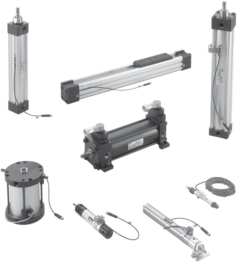
90 Pneumatics Cylinders 89
91 Pneumatics Industry leading aluminum NFPA interchangeable cylinder with flexible construction Bore sizes 1-1/2", 2", 2-1/2", 3-1/4", 4" and 5" Removable bronze alloy gland/bearing for easy maintenance Available in any practical stroke length 20 standard mounting styles available Extruded-profile aluminum body with integrated switch grooves Single rod end or double rod ends Cushions standard and adjustable at both ends, optional non-cushioned RoHS compliant Actuator Products / Tie Rod Cylinders 4MA Series Operating information 4MA 4ML Operating pressure: 250 PSIG (17 bar) 400 PSIG (27 bar) maximum air service maximum hydraulic service Temperature range Standard seals -10 F to 165 F (-23 C to 74 C) Fluorocarbon seals -10 F to 250 F (-23 C to 121 C) Low temperature seals -50 F to 150 F (-46 C to 66 C) Filtration requirements: 40 micron, dry filtered air Filtered hydraulic oil Ordering information 2.00 J 4MA U 1 4 A Bore size Double rod cylinder 12 Specify K only if double rod cylinder is required. Mounting style Specify mounting style code (see table on following page). Cushion head end Blank Non-cushioned head end Series 4MA Air service 4ML Hydraulic service 2 Ports U NPTF R BSPP B BSPT T SAE Piston rod number Specify rod code number for required diameter. 8, 2 Special modification Specify S only for special modification other than rod end, and then describe modification in item notes. (Includes 4MA with Linear Position Sensor Option) 7 C Cushioned head end (not available for 1.50" bore with 1" rod or 4ML) Seals Cylinder construction Blank Standard (nitrile seals) Standard (extruded body, standard round lobe V Fluorocarbon seals 4 Blank* orientation) Fluorocarbon rod wiper and rod E Extruded body, round lobe orientation rotated seal only 5 A* 90 degrees from standard 4 Low temperature seals 4 N* Extruded body, round lobe orientation rotated M Metallic rod wiper, nitrile seals degrees from standard Z* Extruded body, round lobe orientation rotated Piston rod thread style 270 degrees from standard T Aluminum round tube and carbon steel tie rods & nuts * Please reference catalog 0900P-E, table on page B10. Only applies to 1-1/2" to 4" bore size. Piston type 2 Blank Standard (lipseals and magnetic ring) 12 1 Lipseals, no magnetic ring 12 2 Lipseals, no magnetic ring (aluminum piston) 3 Lipseals and magnetic ring (aluminum piston) (standard for 4ML) 4 Bumper seals, no magnetic ring 6 Bumper seals and magnetic ring B Lipseals, 1/4" thick bumpers both ends 3 H Lipseals, 1/4" thick bumper head end 3 C Lipseals, 1/4" thick bumper cap end 3 D Lipseals and magnetic ring, 1/4" thick bumpers both ends 3 F Lipseals and magnetic ring, 1/4" thick bumper head end 3 R Lipseals and magnetic ring, 1/4" thick bumper cap end 3 4 Small male 8 Intermediate male 9 Short female 55 For use with split coupler 9 Special (and specify all 3 dimensions required) 1 Not available with Linear Position Sensor Option (LPSO). 2 Piston Types (blank), 1, 4 and 6 not available for 4ML. Piston Types (blank) and 1 not available for oversize rod numbers 2 and 3. Seals option V only available with Piston Types 2 and 4. Seals option 4 only available with Piston Types 2 and 3. 3 Addition of 1/4" bumper results in a 1/4" stroke loss per bumper, per end. For example, a 6" stroke cylinder with 1/4" bumpers at both ends (option B) has an effective stroke of 5-1/2". 4 Reed and solid-state sensors only available with standard seals or options E and M. See footnote 2. 5 Used for external chemical compatibility applications, not high temperature. 6 If fluorocarbon seals are required with this option, please place an S for special in the Special Modification field and specify the fluorocarbon seals and metallic rod wiper in the item notes. 7 For Linear Position Sensor Option (LPSO), please include the following information for the Special Modification item notes: a. Sensor part number (please reference catalog 0900P-E, pages B100-B104) Stroke length Specify stroke length required in inches. 11 Cushion cap end Blank Non-cushioned cap end Cushioned cap end C (not available for 4ML) Piston rod thread type A Standard (UNF unified thread) W BSF British fine M * Metric * Please reference catalog 0900P-E, page B106. Rod material and gland code Blank Standard rod and gland H Standard rod and HI LOAD gland 17-4 PH stainless steel rod and Y standard gland 17-4 PH stainless steel rod and Z HI LOAD gland 303 stainless steel rod and J standard gland stainless steel rod and K HI LOAD gland stainless steel rod and S standard gland stainless steel rod and T HI LOAD gland 10 b. Sensor position c. Port position (if other than position 1) d. Length of stop tubing, gross stroke and net stroke (if required) Also, Piston Type option (blank), 3, 6, D, F or R is required. 8 Review Piston Rod Selection Chart, please reference catalog 0900P-E, page A14 to determine proper piston rod diameter. 9 For additional information regarding this style, please reference catalog 0900P-E, page B105. If non-standard Rod Material and Gland Code is required with this option, please place an S for special in Special Modification field and specify Rod Material and Gland Code in the item notes. 10 Not available for 4ML. 11 If a stop tube is required, specify gross stroke (net stroke + stop tube) in the model number, then place an S for special in the Special Modification field and specify the stop tube length in the item notes. Not available with Piston Types (blank) and Double rod cylinders not available with composite piston type. 90
92 Pneumatics Mounting Kits and Accessories Bore size Actuator Products / Tie Rod Cylinders 4MA Series Accessories J (MF1) H (MF2) BB (MP1) BC (MP2) BE (MP4) CB (MS1) C (MS2) G (MS7) Head rectangular flange Cap rectangular flange Cap fixed clevis Cap detachable clevis Cap detachable eye Side end angles Side lug (3MA only) Kit fastener torque units Side end lug Kit number Kit number Kit number Kit number Kit number Kit number Kit number Kit number inch-lbs N-m 1-1/2 L L L L L L L L L L L L L L L L /2 L L L L L L L L /4 L L L L L L L L L L L L L L L L L L L L N/A L L N/A ** Spacer plate not used for 4 bore or double rod cylinders Female Rod Clevis CD CW ER Rod Eye Knuckle KK Thread CB CW CE A Symbol A 3/4 3/4 1-1/8 1-5/8 1-5/ /4 CB 3/4 3/4 1-1/4 1-1/2 1-1/ /2 CD 1/2 1/2 3/ /8 1-3/4 C E 1-1/2 1-1/2 2-1/8 2-15/ /16 3-3/4 4-1/2 CW 1/2 1/2 5/8 3/4 3/ /4 ER 1/2 1/2 3/ /8 1-3/4 KK 7/ /2-20 3/4-16 7/ / /2-12 Load capacity (lbs) ER CD CD CD CD CA A Full Thread KK Thread CB Symbol A 3/4 3/4 1-1/8 1-1/8 1-5/ /4 CA 1-1/2 1-1/2 2-1/16 2-3/8 2-13/16 3-7/16 4 CB 3/4 3/4 1-1/4 1-1/2 1-1/ /2 CD 1/2 1/2 3/ /8 1-3/4 ER 23/32 23/32 1-1/16 1-7/16 1-7/ /32 2-1/2 KK 7/ /2-20 3/4-16 7/ / /2-12 Load capacity (lbs) Clevis Bracket M FL F 25 LR R E CW MR DD Dia. 4 Holes CB R E Symbol CB 15/32 3/4 1-1/4 1-1/ /2 CD 7/16 1/2 3/ /8 1-3/4 CW 3/8 1/2 5/8 3/ /4 CW DD 17/64 13/32 17/32 21/32 21/32 29/ E 2-1/4 3-1/ /2 7-1/2 9-1/2 CD+.002 F 3/8 1/2 5/8 3/4 7/8 7/8 FL 1 1-1/2 1-7/8 2-1/ /8 LR 5/8 3/4 1-3/16 1-1/ /4 M 3/8 1/2 3/ /8 1-3/4 MR 1/2 5/8 29/32 1-1/4 1-21/32 2-7/32 R Load capacity (lbs)
93 Pneumatics Actuator Products / Tie Rod Cylinders 4MA Series Accessories Mounting Plate & Eye Bracket M FL F 25 LR R E MR DD Dia. 4 Holes CB R E CD+.002 Symbol CB 15/16 3/4 1-1/4 1-1/ /2 CD 15/16 1/2 3/ /8 1-3/4 DD 17/64 13/32 17/32 21/32 21/32 29/32 E 2-1/4 2-1/2 3-1/2 4-1/ /2 F 3/8 3/8 5/8 7/8 7/8 1-1/8 FL 1 1-1/8 1 7 / 8 2-3/ /8 LR 5/8 3/4 1-1/4 1-1/2 2-1/8 2-1/4 M 3/8 1/2 3/ /8 1-3/4 MR 1/2 9/16 7/8 1-1/4 1-5/8 2-1/8 R Load Capacity (lbs) /2" to 8" Bore Cylinder Accessories Rod end accessories can be selected by cylinder rod end thread size from Table A & B below. Mating parts for rod end accessories are listed just to the right of the knuckle or clevis selected. Mounting plates for style MP1 & MP4 cylinder mounts are selected by bore size from Table C. Rod end thread size Table A Table B Table C Mating parts Mating parts Mounting plates For mtg. style MP1 cylinder For mtg. style MP4 cylinder Female rod clevis Eye bracket Pivot pin Knuckle Clevis bracket Pivot pin Bore size 7/ / / / / / / / / Pivot Pin Maximum pivot angle for rear clevis mounts (BB mounts) and accessories CL CD A Symbol CD 7/16 1/2 3/ /8 1-3/4 CL 1-5/16 1-7/8 2-5/8 3-1/8 4-1/8 5-3/16 Shear cap. (lbs) Note: Pivot Pin must be ordered separately for single lug pivot mounting. Bore 1-1/ /2 3-1/ Angle A
94 Pneumatics Actuator Products / Tie Rod Cylinders 4MA Series Accessories Service Kits Bore size Rod dia. Rod no. RG - Rod gland cartridge kit. Includes gland and wiper, rod, and o-ring seals Nitrile seal kit number Gland to head torque units Fluorocarbon seals kit number Ft-lbs Nm PK - Piston seal kit, SK - complete cylinder kit. standard lipseals. Includes rod gland kit, piston Includes piston and o-ring sealsseal kit, and cushion kits Nitrile seal kit number Fluorocarbon seal kit number Nitrile seal kit number Fluorocarbon seal kit number 1-1/2 5/8 1 RG04MA0061 RG04MA SK15104MA1 SK15104MA5 PK1504MA01 PK1504MA RG04MA0101 RG04MA SK15304MA1 SK15304MA5 5/8 1 RG04MA0061 RG04MA SK20104MA1 SK20104MA5 2 PK2004MA01 PK2004MA RG04MA0101 RG04MA SK20304MA1 SK20304MA5 2-1/2 5/8 1 RG04MA0061 RG04MA SK25104MA1 SK25104MA5 PK2504MA01 PK2504MA RG04MA0101 RG04MA SK25304MA1 SK25304MA5 3-1/4 1 1 RG04MA0101 RG04MA SK32104MA1 SK32104MA5 PK3254MA01 PK3254MA05 1-3/8 3 RG04MA0131 RG04MA SK32304MA1 SK32304MA5 1 1 RG04MA0101 RG04MA SK40104MA1 SK40104MA5 4 PK4004MA01 PK4004MA05 1-3/8 3 RG04MA0131 RG04MA SK40304MA1 SK40304MA5 1 1 RG04MA0101 RG04MA SK50104MA1 SK50104MA5 5 PK5004MA01 PK5004MA05 1-3/8 3 RG04MA0131 RG04MA SK50304MA1 SK50304MA5 1-3/8 1 RG04MA0131 RG04MA SK60104MA1 SK60104MA5 6 PK6004MA01 PK6004MA05 1-3/4 3 RG04MA0171 RG04MA SK60304MA1 SK60304MA5 1-3/8 1 RG04MA0131 RG04MA SK80104MA1 SK80104MA5 8 PK8004MA01 PK8004MA05 1-3/4 3 RG04MA0171 RG04MA SK80304MA1 SK80304MA5 Torque units endcap fastener or tie rod inch-lbs Nm
. Stainless steel piston rods are standard up to 1.")
 for SR and SRM 100 PSIG (7 bar) for SRD/SRDM Temperature range: -10 F to 165 F (-23 C to 74 C) for SR 14 F to 140 F (-10 C to 60 C) for SRM 32 F to 160 F (0 C to")
95 Pneumatics Round Body Cylinders SR Series 304 stainless steel cylinder body, non repairable construction Aluminum heads and caps, Delrin heads and caps are optional 12 bore sizes 5/16" through 3" (see dimensional tables for SRM and SRD/SRDM exclusions). Stainless steel piston rods are standard up to 1.50" bore 28 standard mounting styles (not all available on SRM and SRD/SRDM see table on following page) Single and double acting Adjustable cushions optional on both ends Operating information Operating pressure: 250 PSIG (17 bar) for SR and SRM 100 PSIG (7 bar) for SRD/SRDM Temperature range: -10 F to 165 F (-23 C to 74 C) for SR 14 F to 140 F (-10 C to 60 C) for SRM 32 F to 160 F (0 C to 71 C) for SRD/SRDM Filtration requirements: 40 micron, dry filtered air Ordering information 1.06 C D SR B V C 2.00 Bore Size /16".44 7/16".56 9/16".75 3/4".88 7/8" /16" /4" /2" /4" " /2" " Cushion Head 2 Use C only when cushion head is required. Double Rod Use K only when double rod is required. Available on DX and DXH mounting only. Series SR SRM SRD SRDM Mounting 1 N, NR, NRP, P, R, RP, D, DP, DXP, DX, DXH, A, RA, AP, AR, BRN, BRR, BFD, BRD, BFN, BFR, TRN, TRR, TFD, TRD, TFN or TFR. Standard cylinder With magnetic piston With delrin caps With delrin caps and magnetic piston Piston Blank No bumpers B With bumpers 3 1 Bore sizes and mounting styles are limited by series. See table on next page for availability. 2 Cushions not available on SRD/SRDM series or KDX mounts. 3 Bumpers may increase cylinder length. Please reference catalog 0900P-E, page D37 for adders. 4 Fluorocarbon seals not available on SRM or SRDM series. Cushion Cap 2 Use C only when cushion cap is required. Non-Standard PIston Rod Use 3 only when special piston rod end is required. Specify CC, LE and A Dimensions (See next page.) Non-Standard Rod Specify Y for stainless steel piston rod. Stainless steel is standard on all bore sizes up to and including 1.50" Bore. Special Use S only if special modifications are required, except piston rod end. Seals Blank Standard seals V Fluorocarbon seals 4 W Rod wiper Sensors For sensors, see pages Stroke Specify in inches. 94
96 Pneumatics Round Body Cylinders SR Series Piston Rod Clevis Assembly includes pin and (2) retainer rings and (1) jam nut. A Thread Pivot Brackets F G Nut C D E J B H Dia. Pin K L Bore size Part number 5/16 L /16, 9/16 L L * 3/4, 7/8 L L * 1-1/16 L L * 1-1/4, 1-1/2 L L * 1-3/4, 2, 2-1/2 L L * 3 L * Stainless Steel for use with SRD/SRDM cylinders. G G D K L L K H Radius D Dia. M C B A F Bore size Part number 7/16 L /4, 7/8, 1-1/16 L * 1-1/2 L Pivot Bracket Assembly Assembly includes pin and (2) retainer rings. 5/16" bore only Bore size Part number 5/16 L /16, 9/16 L L * 3/4, 7/8 L /16 L * 1-1/4 L /2, 1-3/4 L L * 2, 2-1/2 L L * 3 L * Stainless Steel for use with SRD/SRDM cylinders. SR Series Trunnion Brackets Select brackets for SR series trunnion mount cylinders from the table below. (Note: trunnion brackets are ordered as a separate item from the cylinder.) L K H Rad. J Dia. Bore size Part number 7/16 L /4, 7/8, 1-1/16, 1-1/2 L K L M F B A D E C Most popular. 95
97 Pneumatics Round Body Cylinders SR Series Foot Brackets Bore size A B C D E F G H J K L Part number 5/ L / L / L /16, 9/ L L * 3/ L /4, 7/8, 1-1/16 1-1/4, 1-1/ L L * L L * 1-3/ L L L * 2-1/ L L * Stainless Steel for use with SRD/SRDM cylinders. Mounting Nut Bore size A B C Part number 5/ /4-28 L /16, 7/ /8-24 L /16, 9/ /16-20 L L * 3/ /2-20 L /4, 7/8, 1-1/ /8-18 L L * 1-1/4, 1-1/ /4-16 L /4, 1-1/ /4-16 L * 1-3/ L /4-12 L L * 2-1/ /8-12 L /2-12 L * Stainless Steel for use with SRD/SRDM cylinders. Most popular. 96
 Temperature range: Working -20 C to 80 C (-4 F to 176 F) High temperature version 20mm, 25mm -10 C")
98 Pneumatics Conforms to ISO 6432 and CETOP RP52P standards 5 bore sizes, 10mm to 25mm Stainless steel body with black anodized aluminum end caps Stainless steel piston rod Magnetic piston and bumpers standard Round Body Cylinders P1A Series Operating information Operating pressure: 10 bar (145 PSIG) Temperature range: Working -20 C to 80 C (-4 F to 176 F) High temperature version 20mm, 25mm -10 C to 150 C (14 F to 302 F) 10mm, 12mm, 16mm -10 C to 120 C (14 F to 248 F) Low temperature version -40 C to 60 C (-40 F to 140 F) Filtration requirements: 40 micron, dry filtered air Ordering information P1A S 016 M S 0025 Bore size mm mm mm mm mm Cylinder type / function Double-acting, adjustable cushioning. M Ø16-25 mm. Not for sealing material type F. Double-acting, bumpers, D Ø10 - Ø25 Double-acting, adjustable cushioning, F double rod, Ø16-25 mm. Not for sealing material type F. Double-acting, bumpers, double rod, K Ø10 - Ø25 Single-acting, bumpers, spring return S for retract stroke, Ø10-25 mm Single-acting, bumpers, spring extend T for advance stroke, Ø16-25 mm Stroke length, mm E.g = 25 mm For standard stroke length and max length see table below. Sealing material Standard S -20 C to +80 C (-4 F to +176 F) Magnetic piston High temperature: Ø12 mm, 16 mm, 20 mm and 25 mm F -10 C to +150 C. (14 F to 302 F) Non magnetic piston External seals of fluorinated rubber V -20 C to +80 C (-4 F to +176 F) Magnetic piston Stroke Lengths Cylinder Bore Stroke Length ( = standard, = non-standard, blank = N/A) model size * * 80* 100* 125* 160* 200* 250* 320* 400* 500* Double acting with fixed end-cushioning: P1A-S 010 D 10 P1A-S 012 D 12 P1A-S 016 D 16 P1A-S 020 D 20 P1A-S 025 D 25 Double acting with adjustable end-cushioning: P1A-S 016 M 16 P1A-S 020 M 20 P1A-S 025 M 25 Single acting: P1A-S 010 SS 10 P1A-S 012 SS 12 P1A-S 016 SS(TS) 16 ** P1A-S 020 SS(TS) 20 P1A-S 025 SS(TS) 25 * Standard stroke lengths in mm according to ISO 4393 ** Not for the TS version Sensors For sensors, see pages
99 Pneumatics Round Body Cylinders P1A Series Flange - MF8 Cylinder Ø mm Part number 10 P1A-4CMB P1A-4DMB 20, 25 P1A-4HMB B C A D E Foot - MS3 Cylinder Ø mm Part number 10 P1A-4CMF P1A-4DMF 20, 25 P1A-4HMF G C D E B A H I F Cover Trunnion Cylinder Ø mm Part number 10 P1A-4CMJ P1A-4DMJ 20, 25 P1A-4HMJ D E ØF C B ØA G H Mounting Nut Cylinder Ø mm Part number A C B Most popular. 98
100 Pneumatics Round Body Cylinders P1A Series Clevis Bracket Cylinder Ø mm Part number 10 P1A-4CMT 12, 16 P1A-4DMT 20, 25 P1A-4HMT I D H E F J G + Stroke A C B Rod clevis Cylinder Ø mm Part number I±J 10 P1A-4CRC D P1A-4DRC C G 20 P1A-4HRC E F 25 P1A-4JRC B H D A Swivel Rod Eye Cylinder Ø mm Part number A 10 P1A-4CRS P1A-4DRS 20 P1A-4HRS 25 P1A-4JRS C J±L G B H D I E F Rod Nut Cylinder Ø mm Part number F D E Most popular. 99
 maximum -5 C to 60 C (23 F to 140 F)")

101 Pneumatics Compact Cylinders P1Q Series Economical square body compact cylinder 10 bore sizes available 12mm - 100mm 4 flexible mounting options Female and male rod ends available Bumpers standard on all models Magnetic and non-magnetic contruction available Operating information Operating pressure: Temperature range: Filtration requirements: 10 bar (145 PSIG) maximum -5 C to 60 C (23 F to 140 F) 40 micron, dry filtered air Metric Double Acting / Magnetic - Female Threaded Piston Rod 12mm Stroke (mm) Order Code 5 P1QS012DC7G P1QS012DC7G P1QS012DC7G P1QS012DC7G P1QS012DC7G mm 5 P1QS016DC7G P1QS016DC7G P1QS016DC7G P1QS016DC7G P1QS016DC7G mm 10 P1QS020DC7G P1QS020DC7G P1QS020DC7G P1QS020DC7G P1QS020DC7G P1QS020DC7G mm 10 P1QS025DC7G P1QS025DC7G P1QS025DC7G P1QS025DC7G P1QS025DC7G P1QS025DC7G0050 Most popular. 32mm Stroke (mm) Order Code 10 P1QS032DC7N P1QS032DC7N P1QS032DC7N P1QS032DC7N P1QS032DC7N P1QS032DC7N P1QS032DC7N P1QS032DC7N mm 15 P1QS040DC7N P1QS040DC7N P1QS040DC7N P1QS040DC7N P1QS040DC7N P1QS040DC7N P1QS040DC7N mm 15 P1QS050DC7N P1QS050DC7N P1QS050DC7N P1QS050DC7N P1QS050DC7N P1QS050DC7N P1QS050DC7N mm Stroke (mm) Order Code 15 P1QS063DC7N P1QS063DC7N P1QS063DC7N P1QS063DC7N P1QS063DC7N P1QS063DC7N mm 15 P1QS080DC7N P1QS080DC7N P1QS080DC7N P1QS080DC7N P1QS080DC7N P1QS080DC7N mm 15 P1QS100DC7N P1QS100DC7N P1QS100DC7N P1QS100DC7N P1QS100DC7N P1QS100DC7N0075 Sensors For sensors, see pages
102 Pneumatics Compact Cylinders P1Q Series Ordering information P1Q S 032 D C 7 N 0025 Cylinder versions S Metric version Function Double D acting Stroke length See below table for standard stroke lengths in mm. Bore size mm mm mm mm mm mm mm mm mm mm Material Bore sizes 12mm - 32mm only available in stainless steel. C Bore sizes 40mm - 100mm only available in chrome plated steel. Mounting style Female thread 7 Both ends threaded F Foot brackets J Front flange A Clevis bracket H Rear flange Male thread 8 Both ends threaded 9 Foot brackets 4 Front flange 2 Clevis bracket 5 Rear flange Cylinder ports & magnet function * Magnet G M5 threads N NPT threads No magnet B M5 threads E NPT threads * Bore sizes 12-25mm are M5 threaded ports, NPT threads only available bore with sizes mm. Standard strokes Bore size

103 Pneumatics Compact Cylinders P1Q Series Clevis Mounting Style A, 2 Intended for flexible mounting of cylinder. Clevis bracket can be fitted to the rear of cylinder. Ø12 - Ø25 E M Material Clevis bracket: surface treated steel, black ØCD M E Supplied complete with mounting screws for attachment to cylinder. CU CW RR CX CZ 4-ØN Bore size Part number Ø32 - Ø100 E M 12 P1Q-4DMT ØCD M E 16 P1Q-4FMT 20 P1Q-4HMT 25 P1Q-4JMT 32 P1Q-4KMT CU CW RR CX CZ 4-ØN 40 P1Q-4LMT 50 P1Q-4MMT 63 P1Q-4NMT 80 P1Q-4PMT 100 P1Q-4QMT Jam Nut Intended for fixed mounting of accessories to the piston rod. Materials Galvanized steel Cylinders supplied with galvanized nut. S M KK Bore size Part number 12 L L L L L L L L L L


104 Pneumatics Compact Cylinders P1Q Series Rod Eye Rod eye for articulated mounting of cylinder. Rod eye can be combined with clevis bracket. Maintenance-free. EM ØCK ER Material Rod eye, nut: galvanized steel LE CA Bore size Part number 12 P1M-4DRE 16 P1M-4FRE 20 P1M-4HRE 25 P1M-4JRE 32 P1M-4LRE 40 P1M-4LRE 50 P1M-4MRE 63 P1M-4MRE 80 P1M-4PRE E KK Th d x A Depth Rod Clevis Clevis for articulated mounting of cylinder. O Material Clevis, clip, nut: galvanized steel Pin: hardened steel ØEK CL CM ER LE CE Bore size Part number 12 P1M-4DRC 16 P1M-4FRC 20 P1M-4HRC 25 P1M-4JRC 32 P1M-4LRC 40 P1M-4LRC 50 P1M-4MRC 63 P1M-4MRC 80 P1M-4PRC E KK Th d x A Depth 103


105 Pneumatics Low profile design Flexible construction with special modification capability High density iron rod bearing provides maximum support for longer life Single and double acting versions available 6 mounting styles 8 bore sizes from 9/16" to 4" Strokes from 1/8" to 6" Permanent lubrication Non-lube service Compact Cylinders LP / LPM Series Operating information Operating pressure: 200 PSIG (17 bar) Temperature range: LP -10 F to 200 F (-23 C to 93 C) LPM -10 F to 140 F (-23 C to 60 C) Filtration requirements: 40 micron, dry filtered air Ordering information 1.50 K N LP L V B E S " Bore size Series 0.56" LP 0.75" LPM 1.12" 1.50" 2.00" 2.50" 3.00" 4.00" Double rod cylinder Blank Single rod K Double rod Mounting style N Basic (Std.) Single rod styles 4F Head bolt 4R Cap bolt 2F Head trunnion 1 2R Cap trunnion 1 1 Cap pivot eye Double rod styles N Basic 4R Cap bolt 2F Head trunnion Hollow rod styles 1,2,5 NH Basic 4RH Cap bolt 2FH Head trunnion Standard Magnetic Piston 5 Piston seal Blank Standard seal L Lipseal piston seal 3 Seals Blank V Standard Class 5 seals Bumpers* Blank No bumpers B Bumpers both ends H Head end only C Cap end only 4 * Please reference catalog 0900P-E, page E60 for stroke reduction. Spring Blank None E Spring extended R Spring return Special features Blank No special feature S Special feature Stroke length Specify stroke length required in inches. Rod end thread style 9 Standard female rod end 4 Optional male rod end 3 Special rod end (specify dimensions or sketch) 1 Not available on 9/16" bore. 2 Hollow rods are used on double rod cylinders. All hollow rod options require the double rod prefix K. 3 Lipseal piston is not available on LPM Series. 4 Not available on spring extend. 5 LPM Series with hollow rod option are not available on the 9/16", 3/4" and 1-1/8" bore sizes. Note: For sensor specifications and part numbers, please refer to the Electronic Sensors section. Sensors For sensors, see pages
 Temperature")
106 Pneumatics Guided Cylinders P5T Series Compact guided cylinder for short stroke applications 9 Bore sizes, 16mm to 200mm Strokes 10 to 100mm depending on model Standard dowel holes on body and tool plate High load bearing option Internal bumpers and magnetic piston are standard Flexible porting: top, rear, side Operating information Operating pressure: 1 MPa (145 PSIG / 10 bar) Temperature range: Nitrile seals (standard) 0 F to 165 F (-18 C to 74 C) Fluorocarbon seals* 0 F to 250 F (-18 C to 121 C) * See fluorocarbon seal option for high temperature applications. Filtration requirements: 40 micron, dry filtered air Ordering information P5T J 032 D H S N 100 Shaft / bearing type J Composite bearing, chrome plated shaft (std) H Ball bearing, stainless steel shaft C Composite bearing, stainless steel shaft Bore size mm mm mm mm mm mm mm mm mm Port location / mounting D Dowel holes, top ports (std) R Dowel holes, rear ports, top plugged (std) S Dowel holes, side ports 1 and top ports Seals S F Nitrile (std) Fluorocarbon (high temp) Stroke length See table below for standard stroke lengths. Consult factory for special stroke lengths. Options N None (std) B High load bearings 2 A Bumpers, adjustable stop collars (extend only) and dual tool plate (side ports rec) 3, 4 E Bumpers and adjustable stop collars (extend only) 3 G High load bearings, bumpers and adjustable stop collars (extend only) 2, 3 D Dual tool plate 3, 4 X Special Port style H NPTF (std) G BSPP P Flow control, BSPP port, prestolok tube (mm) 1 F Flow control, NPTF port, prestolok tube (inch) 1 B Flow control, BSPP 1 N Flow control, NPTF 1 Standard strokes (mm)* Bore size (mm) * Consult factory for special stroke lengths. NOTES: 1 Cannot combine flow controls, side ports and 25mm stroke. 2 Not available with rear mounting and ports. 3 Not available with rear port location (R). 4 Includes high load bearings as standard. Sensors For sensors, see pages

107 Pneumatics 3 body styles (Thrust, Reach, Base) 8 bore sizes 20mm to 100mm Maximum strokes 400 to 1000mm depending on model 3 Bearing options: composite, ball bearing, self-aligning ball bearing Dowel holes standard on body and tool plate Available with adjustable stroke and shock absorbers Direct mount of thrust and reach to same size base Powered by P1L cylinder Guided Cylinders P5L Series Operating information Operating pressure: 10 bar (145 PSIG) Temperature range: Standard seals -17 C to 74 C (0 F to 165 F) Fluorocarbon seals* -17 C to 121 C (0 F to 250 F) * See fluorocarbon seal option for high temperature applications. Operating characteristics: Double acting Filtration requirements: 40 micron, dry filtered air Ordering information P5L R L 100 J1 A A N F N 0900 A Series T Thrust slide R Reach slide B Base slide Cylinder type L P1L cylinder Bore size mm mm mm mm mm mm mm mm Bushings J1 Composite bushing, chrome plated shafts J2 Composite bushing, oversized chrome plated shafts J3 Composite bushing, stainless steel shafts J4 Composite bushing, oversized stainless steel shafts G1 Composite bushing, chrome plated shafts, contaminent tolerant seals G3 Composite bushing, stainless steel shafts, contaminent tolerant seals H3 Linear ball bearings, stainless steel shafts H5 Linear ball bearings, carbon steel shafts S3* Self aligning linear ball bearings, stainless steel shafts S5* Self aligning linear ball bearings, carbon steel shafts * Not avaialble 20mm bore models Extend options N None A Shock/stroke adjusters B Bumpers (base slides only) C Cushions both ends E Micro-adjusters and cushions (both ends only) H Cushions and bumpers (includes options C & K) K Bumpers and adjustable stop collars L Shock absorbers and bumpers (N/A on base slides) Cylinder seals N Nitrile (standard) V Fluorocarbon (high temperature) Retract options N None A Shock/stroke adjusters B Bumpers only C Cushions both ends E Micro-adjusters and cushions (both ends only) H Cushions and bumpers (includes options C & K) K Bumpers and adjustable stop collars L Shock absorbers and bumpers (N/A on base slides) Design series A Current design Stroke length Order in 1mm increments. T-slots Standard (Extruded T-slots on sizes 20-40, no T-slots on sizes ) A ** Machined T-slots (Sizes ) ** Not avaialble on sizes Proximity sensor options N No Sensor P PNP, lead type R NPN, lead type S PNP, plug in type T NPN, plug in type W Prox ready, 8mm (no sensor supplied) Z Prox ready, 12mm (no sensor supplied) Note: Piston magnet is standard on all cylinders. Inductive proximity sensors are included with Options P, R, S & T. Cylinder port style G BSPT ports H NPTF ports P BSPT ports w/ Presto-lok flow controls (mm) F NPTF ports w/ Presto-lok flow controls (inch) B BSPT ports w/ flow controls N NPTF ports w/ flow controls Order P8S Series reed and solid state sensors separately from Electronic Sensors Section. Sensors See pages
108 Pneumatics Guided Cylinders HB Series Medium duty to extremely heavy duty linear motion Powered by the 3MA or 4MA NFPA cylinder, with ISO options available Bore sizes 1-1/2", 2", and 2-1/2" Thrust, reach, and compact versions available Shock absorber, bumpers/stop collars, and proximity sensor options available Operating information Operating pressure: Maximum 100 PSIG (7 bar), air 4MAJ cylinder 150 PSIG (10 bar), air P1D cylinder 250 PSIG (17 bar), air 3MA, 4MA and 2A cylinders 400 PSIG (28 bar), oil 4ML cylinder only 750 PSIG (52 bar), oil 3L cylinder only Temperature range: Cylinder Standard seals 0 F to 165 F (-18 C to 74 C) Fluorocarbon seals* 0 F to 250 F (-18 C to 121 C) * See fluorocarbon seal option for high temperature applications. Not available for 3MA or rod lock cylinders. Filtration requirements: 40 micron, dry filtered air Ordering information for HBC, HBT and HBR HBT A P1 T F 4A B Series HBC HBT HBR Compact slide Thrust slide Reach slide Model /2" bore, 20mm shaft 20 2" bore, 25mm shaft /2" bore, 30mm shaft Stroke length Order in 1" increments. 4 For 3-position units, specify intermediate and total stroke separated by a "/", i.e. 02/06. Consult factory for strokes over 36". Bushings T Composite (standard) D Linear ball bearing T1 Composite with oversized support shafts TC Composite with contaminant-tolerant seals Design Series B Current design level Special Options Blank standard (Two digit code assigned by factory and applies when any "X" appears in the model number or when special options or features are required.) Slide Configuration Options Proximity Sensor Options Blank None Blank None A Shock absorber, both ends P PNP, flying lead type A1 Shock absorber, extend only N NPN, flying lead type A2 Shock absorber, retract only P1 PNP, plug-in connector A3 Shock ready, both ends N1 NPN, plug-in connector A4 Shock ready, extend J 8mm sensor mounting A5 Shock ready, retract bracket, no sensor supplied B Bumpers both ends 1 J1 12mm sensor mounting B1 Bumper & adjustable stop collar, bracket, no sensor supplied extend only Note: 8mm inductive proximity sensors are included with Options P, N, P1, N1. B2 Bumper retract only Magnetic piston is standard for 3MA, 4MA, B3 Bumper & adjustable stop collar, 4MAJ, 4ML and P1D cylinders. Order retract only reed and solid state sensors separately B4 Bumper & adjustable stop collar, for these cylinders from the Electronic both ends Sensors section. C Cushions on cylinder, both ends 2 C1 Cushion on cylinder, extend only Other Options (More than one selection is possible) C2 Cushion on cylinder, retract only 2 Blank None X Special slide configuration (please specify) F Flow controls (presto-lok) G Flow controls (NPT) K Stainless steel support shafting NOTES 1 Option B includes options B1 and B2. 2 Cushions are not available with 4ML cylinders or 3MA cylinders on HB products. 3 Fluorocarbon seals not available with 3MA or rodlock cylinders. 4 P1D cylinders have strokes only in whole mm. The HB inch stroke will be changed (rounded up) to reflect this. Sensors For sensors, see pages Cylinder Options (More than one selection is possible) Blank None V Fluorocarbon cylinder seals 3 L1 Left hand assembly L3 Cylinder ports at position 3 Cylinder Type 3A 3MA NFPA air cylinder, NPTF ports 2 4A 4MA NFPA air cylinder, NPTF ports 4J 4MAJ NFPA air cylinder with manual override rodlock, NPTF ports, 100 PSIG max. D P1D ISO cylinder w/ removable gland, BSPP ports D1 P1D ISO cylinder w/ removable gland, Standard Rodlock, BSPP ports D2 P1D ISO cylinder w/ removable gland, manual override rodlock, BSPP ports E P1D ISO cylinder w/ removable gland, NPTF ports E1 P1D ISO cylinder w/ removable gland, standard rodlock, NPTF ports E2 P1D ISO cylinder w/ removable gland, manual override rodlock, NPTF ports 4L 4ML NFPA hydraulic cylinder, NPTF ports, 400 PSIG max. 2 S 2A NFPA steel air cylinder, 250 PSIG max. S1 3L NFPA steel hydraulic cylinder, 750 PSIG max. Q No cylinder, NFPA cylinder mounting Q1 No cylinder, ISO cylinder mounting X Special cylinder type (please specify) 107
 Minimum pressure: Ø16, Ø20 bores 29 PSI (2 bar) Ø25, Ø32, Ø40 bores 14.5 PSI (1 bar) Ø50, Ø63 bores 7 PSI (0.")
 Temperature range: 40 F to 140 F (5 C to 60 C) Filtration requirements: Filtered, nonlubricated compressed air Ordering Information P1X N 032 D A N 0500 W D N N N -B Series P1X Global Rodless")
109 Pneumatics 7 bore sizes 16mm through 63mm Two port locations standard Large carriage for stability Integral sensor mounting rail Optional adjustable stroke and shock absorbers Rodless Cylinders P1X Series Operating information Maximum pressure: 100 PSIG (7 bar) Minimum pressure: Ø16, Ø20 bores 29 PSI (2 bar) Ø25, Ø32, Ø40 bores 14.5 PSI (1 bar) Ø50, Ø63 bores 7 PSI (0.5 bar) Proof pressure: 152 PSI (10.5 bar) Temperature range: 40 F to 140 F (5 C to 60 C) Filtration requirements: Filtered, nonlubricated compressed air Ordering Information P1X N 032 D A N 0500 W D N N N -B Series P1X Global Rodless Construction N Inch M Metric Carriage D Double acting Seal material N Standard Stroke length* Basic or options B Standard W With options / Special (for factory use only) Porting options N NPTF G BSPP Q BSPT* * Not available with N construction Bore size mm mm mm mm mm mm mm Piston / Shock style A Cushions both ends (standard) R Cushion right end only* L Cushion left end only* N No cushions or shock absorbers H Shock absorber both ends** B Shock absorber right end only** C Shock absorber left end only** * As viewed from port side of cylinder ** Cannot be combined with inverted carriage * Stroke is ALWAYS in mm. When B is specified, the remaining digits in the part number are not necessary. If W is used, the remaining digits in the part number must be filled out. Not available on 40, 50 and 63mm bore sizes. Carriage mounting style Standard Inverted Carriage mounting D (std) J Single, basic mount A G Single, swivel mount Mounting options No Foot mount mount foot bracket Bottom mount foot bracket Intermediate supports N F A No support H M B One support K P C Two supports T R D Three supports Essential Information Optional Features Sensors For sensors, see pages Fastener Type N Standard - zinc-plated S Stainless steel 108
110 Pneumatics Rodless Cylinders P1Z Series Available in 3 bores with stroke lengths up to 2000 mm Adjustable air cushioning is available on all cylinders The load is fixed onto the mobile carriage by 4 tapped holes The cylinder is attached by the ends with jam nuts, flanges or foot mounts Technical data Bore size Weights Weight at zero stroke Weight per 25mm of stroke mm inch kg lbs kg lbs 16 5/ / / Operating information Maximum pressure: Minimum pressure: Temperature range: Filtration requirements: 100 PSIG (7 bar) 29 PSI (2 bar) 14 F to 140 F (-10 C to 60 C) Dry, filtered compressed air to ISO class or better If external lubrication is added, this must always be continued. Specifications for P1Z series magnetically coupled rodless Bore size mm (inch nominal) 16 (5/8) 20 (3/4) 32 (1 1/4) Port size M5 BSPP, NPT 1/8 BSPP, 1/8 NPT 1/8 BSPP, 1/8 NPT Maximum stroke mm (inch) 1000 (39.4) 1500 (59.1) 2000 (78.7) Stroke tolerance mm +1.5/-0 <= /-0; > /-0 Piston speed m/s (inch/sec) 0.1 to 0.4 (4 to 15.75) Max. coupling force N (lbs) 157 (35) 236 (53) 703 (158) Cushion Lubrication Air cushion standard Not required (If you choose to lubricate your system, continuing lubrication will be required.) Ordering information Standard cylinder (15 positions) Options (16 positions) P 1 Z M S N N B F M Bore 016 Ø 16 mm 020 Ø 20 mm 032 Ø 32 mm Cushioning N None (Ø 16 only) A Adjustable Cushions Strokes mm mm Mounting kit* F Footmount L Flanges N None (std.) * Cylinders are supplied with mounting nuts fitted on each endplate. Ø Stroke (mm) (in) 16 0 to to to to to to 78.7 Options * B None W With options Standard when B option is used. Cylinder port type M Metric (Ø 16 only) B BSPP (Ø 20 & 32) N NPTF (Ø 20 & 32) Order code examples: - P1ZM016SNN0100B Ø 16 mm bore 100 mm stroke cylinder supplied with mounting nut on each endplate - P1ZM020SAN1000WFBN Ø 20 mm bore 1 m stroke cylinder with foot mount on each endplate 109
 (in) 16 0 to 750 0 to 29.5 20 0 to 1000 0 to 39.4 32 0 to 1000 0 to 59.")
 B BSPP (Ø 20 & 32) N NPTF (Ø 20 & 32) Standard when B option is used. of stroke sensing NPN PNP Reed Sensors type (Qty: 2) L With rail, no sensor N (std.")
111 Pneumatics Rodless Cylinders P1Z Series Ordering information Standard cylinder (15 positions) Options (16 positions) P 1 Z M T C N B N M Bore 016 Ø 16 mm 020 Ø 20 mm 032 Ø 32 mm Ø Stroke (mm) (in) 16 0 to to to to to to 59.1 Function G Guided T Guided with transfer porting Cushioning C Adjustable stop H Hydraulic shock absorber Strokes mm mm Options B None W With options Cylinder port type M Metric (Ø 16 only) B BSPP (Ø 20 & 32) N NPTF (Ø 20 & 32) Standard when B option is used. of stroke sensing NPN PNP Reed Sensors type (Qty: 2) L With rail, no sensor N (std.) No sensor rail Note: Order Sensors separately. Order code examples: - P1ZM016GCN0100B Ø 16 mm bore 100 mm stroke cylinder supplied with adjustable stop - P1ZM020GHN1000WNBL Ø 20 mm bore 1 m stroke cylinder with hydraulic shock absorbers and rail for sensors Range Magnetic rodless cylinder, guided version Available in 3 diameters with possible strokes up to 1500 mm (59 in). 4 tapped mounting holes on the carriage. cap mounting provided by 4 tapped and counterbored holes. Options External adjustable bumpers Can be fitted on cylinder endcaps and provide noise reduction and adjustment at the end of stroke. Used when light loads and short strokes. Pneumatic air supply on one side only (transfer porting option). External hydraulic shock absorbers Self-compensating hydraulic shock absorbers can be used instead of bumpers for a greater cushioning effect at the end of stroke. They are recommended for arduous applications. Reed or solid state sensors: A rail fitted on one side only of the cylinder provides mounting and position adjustment of sensors. The rail is located on same side as the end of stroke stops. 110
 Internal bumpers are standard Shock absorbers are available for high inertia loads Operating information Operating pressure: Temperature range: Filtration requirements: 100 PSIG (6.")
112 Pneumatics Rotary PRN Series Single or double vane rotary actuator 3 standard rotations: 90, 180, or 270 Output 0.7 MPa: 16 to 1120 N cm (1.4 to 99 in-lb) Internal bumpers are standard Shock absorbers are available for high inertia loads Operating information Operating pressure: Temperature range: Filtration requirements: 100 PSIG (6.9 bar) -5 C to 80 C (-23 F to 176 F) 40 micron, dry filtered air Ordering information PRNA 20 S S Type PRNA Sizes 1-20 PRN Sizes Sensors For sensors, see pages Size Type S D Single vane Double vane Rotation angle (all sizes, single and double vane) (sizes 50 through 800, double vane only) (all sizes, single vane only) (single vane only, not available on size 1) (sizes 50 through 800, single vane only) Porting Omit Standard porting Rear porting S (sizes 3-20 only) Oscillating reference point* * See specification tables for availability of rotation angle /reference point combinations for the selected model. Reference point and rotation orientations PRNA1S/D, PRNA3S/D, PRNA10S/D PRNA20S/D, PRN30S/D Reference point at Port Position Reference Point PRN50, 150, 300, 800 Reference point at Port Position Reference Point 270 Rotation 90 Rotation 180 Rotation PRN1AS, PRNA3S PRNA10S, PRNA20S Reference point at Rotation PRN50, 150, 300, 800 Reference point at Rotation 180 Rotation Reference Point Port Position 90 Port Position 90 Rotation 180 Rotation Reference Point 280 Rotation 90 Rotation 100 Rotation 180 Rotation 111
113 Pneumatics Electronic Sensors PNP Solid State Sensor Selection Guide Series Compact cylinders Round body cylinders Tie rod cylinders Iso cylinders Rodless cylinders Guided cylinders Rotary actuators Bore size or type 3M flying leads 10m flying leads 8mm quick connect* 8mm quick connect w/ 1 m lead* 12mm quick connect* Bracket Sensor page # P1Q 12mm - 100mm P8S-EPFXS 1 N/A P8S-EPSUS N/A N/A N/A N/A N/A P1M standard sensor P1M right angle sensor LPM P1L SRM/SRDM P All P8S-GPFLX P8S-GPFTX P8S-GPSHX P8S-GPSCX P8S-GPMHX N/A B298 N/A All P8S-SPELXD P8S-SPETXD P8S-SPTHXD N/A N/A N/A B301 N/A 9/16" L N/A L C N/A N/A N/A B305 N/A 3/4" - 1-1/8" L N/A L C N/A N/A N/A B305 N/A 1-1/2" - 2" L N/A L C N/A N/A N/A B305 N/A 2-1/2" - 4" L N/A L C N/A N/A N/A B305 N/A 20-25mm P8S-GPFLX P8S-GPFTX P8S-GPSHX P8S-GPSCX P8S-GPMHX P8S-TMC01 B298 B mm P8S-GPFLX P8S-GPFTX P8S-GPSHX P8S-GPSCX P8S-GPMHX P8S-TMC02 B298 B mm P8S-GPFLX P8S-GPFTX P8S-GPSHX P8S-GPSCX P8S-GPMHX P8S-TMC03 B298 B301 9/16" - 3/4" P8S-GPFLX P8S-GPFTX P8S-GPSHX P8S-GPSCX P8S-GPMHX P8S-TMC01 B298 B /16" - 2-1/2" P8S-GPFLX P8S-GPFTX P8S-GPSHX P8S-GPSCX P8S-GPMHX P8S-TMC02 B298 B /8" - 2-1/2" P8S-GPFLX P8S-GPFTX P8S-GPSHX P8S-GPSCX P8S-GPMHX P8S-TMC02 B298 B301 3" - 4" P8S-GPFLX P8S-GPFTX P8S-GPSHX P8S-GPSCX P8S-GPMHX P8S-TMC03 B298 B301 3MA/4MA standard sensor 1-1/2" - 5" N/A B298 N/A P8S-GPFLX P8S-GPFTX P8S-GPSHX P8S-GPSCX P8S-GPMHX 3MA/4MA 6" - 8" P8S-TMA0X B298 N/A 3MA/4MA mini global sensor P1A standard sensor P1A right angle sensors P1D standard & clean profiles P1D standard profile mini sensors P1D tie rod version 1-1/8" - 5" P8S-MPFLX P8S-MPFTX P8S-MPSHX N/A N/A P8S-TMA0Z B300 N/A 10-25mm P8S-GPFLX P8S-GPFTX P8S-GPSHX P8S-GPSCX P8S-GPMHX P8S-TMC01 B298 B301 10mm P1A-2XMK 1 N/A N/A N/A N/A P1A-2CCC B304 B304 12mm P1A-2XMK 1 N/A N/A N/A N/A P1A-2DCC B304 B304 16mm P1A-2XMK 1 N/A N/A N/A N/A P1A-2FCC B304 B304 20mm P1A-2XMK 1 N/A N/A N/A N/A P1A-2HCC B304 B304 25mm P1A-2XMK 1 N/A N/A N/A N/A P1A-2JCC B304 B304 All P8S-GPFLX P8S-GPFTX P8S-GPSHX P8S-GPSCX P8S-GPMHX N/A B298 N/A All P8S-MPFLX P8S-MPFTX P8S-MPSHX N/A N/A N/A B300 N/A All P8S-GPFLX P8S-GPFTX P8S-GPSHX P8S-GPSCX P8S-GPMHX P8S-TMA0X B298 N/A P1X All P8S-GPFLX P8S-GPFTX P8S-GPSHX P8S-GPSCX P8S-GPMHX P8S-TMA0Y B298 N/A P1Z All P8S-GPFLX P8S-GPFTX P8S-GPSHX P8S-GPSCX P8S-GPMHX N/A B298 N/A OSP-P All KL KL KL3312 N/A N/A N/A B303 N/A P5T Flush mount P8S-GPFLX P8S-GPFTX P8S-GPSHX P8S-GPSCX P8S-GPMHX N/A B298 N/A Right angle P8S-SPELXD P8S-SPETXD P8S-SPTHXD N/A N/A Included w/ sensor P5T2 All P8S-GPFLX P8S-GPFTX P8S-GPSHX P8S-GPSCX P8S-GPMHX N/A B298 N/A P5E All P8S-GPFLX P8S-GPFTX P8S-GPSHX P8S-GPSCX P8S-GPMHX N/A B298 N/A HB All P8S-GPFLX P8S-GPFTX P8S-GPSHX P8S-GPSCX P8S-GPMHX N/A B298 N/A P5L PV WR XR 20-25mm P8S-GPFLX P8S-GPFTX P8S-GPSHX P8S-GPSCX P8S-GPMHX P8S-TMC01 B298 B mm P8S-GPFLX P8S-GPFTX P8S-GPSHX P8S-GPSCX P8S-GPMHX P8S-TMC02 B298 B mm P8S-GPFLX P8S-GPFTX P8S-GPSHX P8S-GPSCX P8S-GPMHX P8S-TMC03 B298 B301 Normally open SMH-1P 2 N/A SMH-1PC N/A N/A N/A B307 N/A Normally closed SMC-1P 2 N/A SMC-1PC N/A N/A N/A B307 N/A PRN(A) All N/A N/A N/A N/A N/A N/A N/A N/A PTR 10, 15 SWH-1P 3 N/A SWH-1PC N/A N/A Included B308 N/A 20, 25, 32 SWH-2P 3 N/A SWH-2PC N/A N/A Included B308 N/A B299 Bracket page # N/A 1. Flying leads are 2 meters in length 2. Flying Leads are 1.5 meters in length 3. Flying leads are 1 meter in length 4. Flying leads are 5 meter in length 112
114 Pneumatics NPN Solid State Sensor Selection Guide Series Compact cylinders Round body cylinders Tie rod cylinders ISO cylinders Rodless Cylinders Guided cylinders Rotary actuators Bore size or type 1 Flying leads are 2 meters in length 2 Flying Leads are 1.5 meters in length 3 Flying leads are 1 meter in length 3m flying leads 10m flying leads 8mm quick connect* Electronic Sensors 8mm quick connect w/ 1m lead* 12mm quick connect* Bracket Sensor page # P1Q 12mm - 100mm P8S-ENFXS 1 N/A P8S-ENSUS N/A N/A N/A N/A N/A P1M standard sensor P1M right angle sensor LPM P1L SRM/SRDM P All P8S-GNFLX P8S-GNFTX P8S-GNSHX P8S-GNSCX P8S-GNMHX N/A B298 N/A All P8S-SNELX P8S-SNETX P8S-SNTHX N/A N/A N/A B301 N/A 9/16" L N/A L C N/A N/A N/A B305 N/A 3/4" - 1-1/8" L N/A L C N/A N/A N/A B305 N/A 1-1/2" - 2" L N/A L C N/A N/A N/A B305 N/A 2-1/2" - 4" L N/A L C N/A N/A N/A B305 N/A 20-25mm P8S-GNFLX P8S-GNFTX P8S-GNSHX P8S-GNSCX P8S-GNMHX P8S-TMC01 B298 B mm P8S-GNFLX P8S-GNFTX P8S-GNSHX P8S-GNSCX P8S-GNMHX P8S-TMC02 B298 B mm P8S-GNFLX P8S-GNFTX P8S-GNSHX P8S-GNSCX P8S-GNMHX P8S-TMC03 B298 B301 9/16" - 3/4" P8S-GNFLX P8S-GNFTX P8S-GNSHX P8S-GNSCX P8S-GNMHX P8S-TMC01 B298 B /16" - 2-1/2" P8S-GNFLX P8S-GNFTX P8S-GNSHX P8S-GNSCX P8S-GNMHX P8S-TMC02 B298 B /8" - 2-1/2" P8S-GNFLX P8S-GNFTX P8S-GNSHX P8S-GNSCX P8S-GNMHX P8S-TMC02 B298 B301 3" - 4" P8S-GNFLX P8S-GNFTX P8S-GNSHX P8S-GNSCX P8S-GNMHX P8S-TMC03 B298 B301 3MA/4MA standard sensor 1-1/2" - 5" N/A B298 N/A P8S-GNFLX P8S-GPNFTX P8S-GNSHX P8S-GPNSCX P8S-GNMHX 3MA/4MA 6" - 8" P8S-TMA0X B298 N/A 3MA/4MA miniglobal sensor P1A standard sensor P1A right angle sensors P1D standard & clean profiles P1D standard profile mini Sensors P1D tie rod version 1-1/8" - 5" P8S-MNFLX P8S-MNFTX P8S-MNSHX N/A N/A P8S-TMA0Z B300 N/A 10-25mm P8S-GNFLX P8S-GNFTX P8S-GNSHX P8S-GNSCX P8S-GNMHX P8S-TMC01 B298 B301 10mm bore P1A-2XLK 1 N/A N/A N/A N/A P1A-2CCC B304 B304 12mm bore P1A-2XLK 1 N/A N/A N/A N/A P1A-2DCC B304 B304 16mm bore P1A-2XLK 1 N/A N/A N/A N/A P1A-2FCC B304 B304 20mm bore P1A-2XLK 1 N/A N/A N/A N/A P1A-2HCC B304 B304 25mm bore P1A-2XLK 1 N/A N/A N/A N/A P1A-2JCC B304 B304 All P8S-GNFLX P8S-GNFTX P8S-GNSHX P8S-GNSCX P8S-GNMHX N/A B298 N/A All P8S-MNFLX P8S-MNFTX P8S-MNSHX N/A N/A N/A B300 N/A All P8S-GNFLX P8S-GNFTX P8S-GNSHX P8S-GNSCX P8S-GNMHX P8S-TMA0X B298 N/A P1X All P8S-GNFLX P8S-GNFTX P8S-GNSHX P8S-GNSCX P8S-GNMHX P8S-TMA0Y B298 N/A P1Z All P8S-GNFLX P8S-GNFTX P8S-GNSHX P8S-GNSCX P8S-GNMHX N/A B298 N/A OSP-P All N/A N/A N/A N/A N/A N/A N/A N/A P5T Flush mount P8S-GNFLX P8S-GNFTX P8S-GNSHX P8S-GNSCX P8S-GNMHX N/A B298 N/A Right angle P8S-SNELX P8S-SNETX P8S-SNTHX N/A N/A N/A B299 N/A P5T2 All P8S-GNFLX P8S-GNFTX P8S-GNSHX P8S-GNSCX P8S-GNMHX N/A B298 N/A P5E All P8S-GNFLX P8S-GNFTX P8S-GNSHX P8S-GNSCX P8S-GNMHX N/A B298 N/A HB All P8S-GNFLX P8S-GNFTX P8S-GNSHX P8S-GNSCX P8S-GNMHX N/A B298 N/A P5L PV WR XR 20-25mm P8S-GNFLX P8S-GNFTX P8S-GNSHX P8S-GNSCX P8S-GNMHX P8S-TMC01 B298 B mm P8S-GNFLX P8S-GNFTX P8S-GNSHX P8S-GNSCX P8S-GNMHX P8S-TMC02 B298 B mm P8S-GNFLX P8S-GNFTX P8S-GNSHX P8S-GNSCX P8S-GNMHX P8S-TMC03 B298 B301 Normally open SMH-1N 2 N/A SMC-1NC N/A N/A N/A B307 N/A Normally closed SMC-1N 2 N/A SMC-1NC N/A N/A N/A B307 N/A PRN(A) All See page B306 PTR 10, 15 SWH-1N 3 N/A SWH-1NC N/A N/A Included B308 N/A 20, 25, 32 SWH-2N 3 N/A SWH-2NC N/A N/A Included B308 N/A Bracket page # 113
115 Pneumatics Electronic Sensors Reed Sensor Selection Guide Series Compact cylinders Round body cylinders Tie rod cylinders ISO cylinders Rodless cylinders Guided cylinders Rotary actuators Bore size or type 3m flying leads 10m flying leads 8mm quick connect* 8 mm quick connect w/ 1 m lead* 12mm quick connect* Bracket Sensor page # P1Q 12mm - 100mm P8S-ERFXS 1 N/A P8S-ERSUS N/A N/A N/A N/A N/A P1M standard sensor P1M right angle sensor LPM P1L SRM/SRDM P All P8S-GRFLX P8S-GRFTX P8S-GRSHX P8S-GRSCX P8S-GRMHX N/A B299 N/A All P8S-SRELX P8S-SRETX P8S-SRTHX N/A N/A N/A B301 N/A 9/16" L N/A L C N/A N/A N/A B305 N/A 3/4" - 1-1/8" L N/A L C N/A N/A N/A B305 N/A 1-1/2" - 2" L N/A L C N/A N/A N/A B305 N/A 2-1/2" - 4" L N/A L C N/A N/A N/A B305 N/A 20-25mm P8S-GRFLX P8S-GRFTX P8S-GRSHX P8S-GRSCX P8S-GRMHX P8S-TMC01 B299 B mm P8S-GRFLX P8S-GRFTX P8S-GRSHX P8S-GRSCX P8S-GRMHX P8S-TMC02 B299 B mm P8S-GRFLX P8S-GRFTX P8S-GRSHX P8S-GRSCX P8S-GRMHX P8S-TMC03 B299 B301 9/16" - 3/4" P8S-GRFLX P8S-GRFTX P8S-GRSHX P8S-GRSCX P8S-GRMHX P8S-TMC01 B299 B /16" - 2-1/2" P8S-GRFLX P8S-GRFTX P8S-GRSHX P8S-GRSCX P8S-GRMHX P8S-TMC02 B299 B /8" - 2-1/2" P8S-GRFLX P8S-GRFTX P8S-GRSHX P8S-GRSCX P8S-GRMHX P8S-TMC02 B299 B301 3" - 4" P8S-GRFLX P8S-GRFTX P8S-GRSHX P8S-GRSCX P8S-GRMHX P8S-TMC03 B299 B301 3MA/4MA standard sensor 1-1/2" - 5" N/A B299 N/A P8S-GRFLX P8S-GRFTX P8S-GRSHX P8S-GRSCX P8S-GRMHX 3MA/4MA 6" - 8" P8S-TMA0X B299 N/A 3MA/4MA mini global sensor P1A standard sensor P1A alternate sensors P1D standard & clean profiles P1D standard profile mini sensors P1D tie rod version 1-1/8" - 5" P8S-MRFLX P8S-MRFTX P8S-MRSHX N/A N/A P8S-TMA0Z B299 N/A 10-25mm P8S-GRFLX P8S-GRFTX P8S-GRSHX P8S-GRSCX P8S-GRMHX P8S-TMC01 B299 B301 10mm bore P1A-2XRL N/A P1A-2XSH N/A N/A P1A-2CCB B304 B304 12mm bore P1A-2XRL N/A P1A-2XSH N/A N/A P1A-2DCB B304 B304 16mm bore P1A-2XRL N/A P1A-2XSH N/A N/A P1A-2FCB B304 B304 20mm bore P1A-2XRL N/A P1A-2XSH N/A N/A P1A-2HCB B304 B304 25mm bore P1A-2XRL N/A P1A-2XSH N/A N/A P1A-2JCB B304 B304 All P8S-GRFLX P8S-GRFTX P8S-GRSHX P8S-GRSCX P8S-GRMHX N/A B299 N/A All P8S-MRFLX P8S-MRFTX P8S-MRSHX N/A N/A N/A B300 N/A All P8S-GRFLX P8S-GRFTX P8S-GRSHX P8S-GRSCX P8S-GRMHX P8S-TMA0X B299 N/A P1X All P8S-GRFLX P8S-GRFTX P8S-GRSHX P8S-GRSCX P8S-GRMHX P8S-TMA0Y B299 N/A P1Z All P8S-GRFLX P8S-GRFTX P8S-GRSHX P8S-GRSCX P8S-GRMHX N/A B299 N/A OSP-P All KL KL KL3302 N/A N/A P5T Included w/ sensor Flush mount P8S-GRFLX P8S-GRFTX P8S-GRSHX P8S-GRSCX P8S-GRMHX N/A B299 N/A Right angle P8S-SRELX P8S-SRETX P8S-SRTHX N/A N/A N/A B299 N/A P5T2 All P8S-GRFLX P8S-GRFTX P8S-GRSHX P8S-GRSCX P8S-GRMHX N/A B299 N/A P5E All P8S-GRFLX P8S-GRFTX P8S-GRSHX P8S-GRSCX P8S-GRMHX N/A B299 N/A HB All P8S-GRFLX P8S-GRFTX P8S-GRSHX P8S-GRSCX P8S-GRMHX N/A B299 N/A P5L PV WR XR 20-25mm P8S-GRFLX P8S-GRFTX P8S-GRSHX P8S-GRSCX P8S-GRMHX P8S-TMC01 B299 B mm P8S-GRFLX P8S-GRFTX P8S-GRSHX P8S-GRSCX P8S-GRMHX P8S-TMC02 B299 B mm P8S-GRFLX P8S-GRFTX P8S-GRSHX P8S-GRSCX P8S-GRMHX P8S-TMC03 B299 B299 N.O. high amp SMR-1 1 N/A SMR-1C N/A N/A N/A B307 N/A N.O. low amp SMR-1L 1 N/A SMR-1LC N/A N/A N/A B307 N/A N.C. SMD-1L 1 N/A SMD-1LC N/A N/A N/A B307 N/A PRN See model code B306 N/A PTR 10, 15 SWR-1 2 N/A SWR-1C N/A N/A Included B308 N/A 20, 25, 32 SWR-2 2 N/A SWR-2C N/A N/A Included B308 N/A B303 Bracket page # N/A 1. Flying leads are 1.5 meters in length 2. Flying Leads are 1 meters in length 3. Flying leads are 2 meter in length 4. Flying leads are 5 meter in length 114
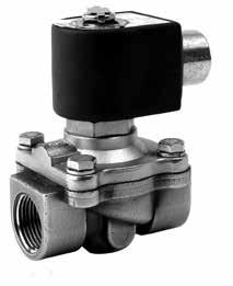


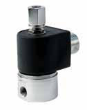
116 Pneumatics Fluid Control Valves ENGINEERING YOUR SUCCESS Aerospace Climate Control Electromechanical Filtration Fluid & Gas Handling Hydraulics Pneumatics Process Control Sealing & shielding 115

117 Pneumatics How to Use this Section Navigation: 5 Easy Steps Fluid Control Valves How to Use this Section 1 2 COILS 3 Please Please refer to refer the to coil the chart coil chart number number within reference the catalog within to find the the catalog correct to coil find in the Fluid chart Control below. Express coil. Gold Ring TM Voltage 1/2 NPT Conduit* DIN 43650A/ISO /60 AF4C01 - CHART 1 120/60-110/50 AF4C05 AFPH05 6 watts, Class F 240/60-220/50 AF4C15 AFPH15 Gold Ring TM Voltage 1/2 NPT Conduit* DIN 43650A/ISO4400 CHART 4 11 watts, Class F 24/60 120/60-110/50 240/60-220/50 CF4C01 CF4C05 CF4C15 - CFPH05 CFPH15 CHART 5 16 watts, Class F 24/60 120/60-110/50 240/60-220/50 DF4C01 DF4C05 DF4C15 - DFPH05 DFPH15 CHART watts, Class F 12VDC 24VDC 3F4C75 3F4C80 3FPH75 3FPH80 DIN Skinner Voltage 1/2 NPT Conduit* Hazardous** 43650A/ISO4400 CHART 7 10 watts, Class F 24/60 120/60-110/50 240/60-220/50 12VDC 24VDC C111B2 C111P3 C111Q3 C111C1 C111C2 D100B2 D100P3 D100Q3 D100C1 D100C2 - H111P3 H111Q3 H111C1 H111C2 CHART 7 10 watts, Class H 120/60-110/50 240/60-220/50 12VDC 24VDC C222P3 C222Q3 C222C1 C222C H222P3 H222Q3 - H222C2 CHART 8 22 watts, Class H 120/60-110/50 12VDC 24 VDC C322P3 C322C1 C322C H322P3 H322C1 H322C2 Skinner Voltage 1/2 NPT Conduit* DIN 43650A/ISO Leads CHART 9 AC 10 watts*** DC 8 watts Class F 24/60 120/60-110/50 240/60-220/50 12VDC 24VDC C4E C4F C4G C4A C4B B4E B4F B4G B4A B4B CHART 9 AC 10 watts*** DC 8 watts Class H 24/60 120/60-110/50 240/60-220/50 12VDC 24VDC D6E D6F D6G D6A D6B * 18 Lead Wires, Nema 1, 2, 3, 4, 4X ** Hazardous location coil approval: Class I, Div I & II, Groups A, B, C, D; Class II, Div I & II, Groups E, F, G; Class III, Div I. *** 8.5 Watt For 2 - Way Normally Closed AC 1. Choose your pressure vessel 2. Choose your coil reference number from the Coil Chart 3. Find your coil reference number on the Coil Chart 4. Place order for pressure vessel and coil as separate items. 5. Request distributor to place order via PHConnect. Find the Coil Chart on page 135 of this catalogue. The stated wattage represents a nominal value. The actual wattage may vary depending on coil/pressure vessel selection. The pressure vessel and solenoid coil are boxed and shipped separately. Quantities of 10 pieces or less will ship next day. Quantities of pieces will ship in 5 working days. Quantities greater than 51 pieces may be scheduled. Images shown in this catalog are representative only. 116


118 Pneumatics How To Design Your Solution Fluid Control Valves How to Design Your Solution Modularity: Order a pressure vessel and mix and match the coils to make endless product capabilities. Stainless Steel Valve DIN Coil Brass Valve 1/2 NPT Conduit Coil Pressure Vessel 1. Select Valve Type 2. Select Operation 3. Choose Body Material 4. Choose Port Size 5. Appropriate Operating Pressure Differential 6. Verify Media Compatibility Coil 1. Select Coil 2. Select Voltage 12 VDC 24 VDC 24/60 120/60-110/50 240/60-220/50 Result: Solenoid valve and coil combinations that ship next day meet your application needs and have a two year warranty. Coils assembled to pressure vessels in the field will carry recognized approval. 117
 PSI Air, Inert Gas Light Oil Max. Media Temp. F Seal Pressure Vessel Number Min. Water Watt AC VOLTAGE 1/8 1/8.")

119 Pneumatics Fluid Control Valves Two-Way Valves 2-Way Direct Acting - Normally Closed - Brass Port Size NPT Orifice Size in. Flow Factor Cv Operating Pressure Differential (MOPD) PSI Air, Inert Gas Light Oil Max. Media Temp. F Seal Pressure Vessel Number Min. Water Watt AC VOLTAGE 1/8 1/ PCTFE 7121KBN1NF00 7 Coil Chart 1/4 1/ PCTFE 7121KBN2NF00 7 1/4 1/ FKM 7121KBN2NV00 7 1/4 5/ FKM 7121KBN2QV00 7 1/4 13/ FKM 7121KBN2SV00 7 1/2 7/ FKM 7121KBN44V00 7 DC VOLTAGE 1/8 1/ PCTFE 7121KBN1NF00 7 1/4 1/ PCTFE 7121KBN2NF00 7 1/4 1/ FKM 7121KBN2NV00 7 1/4 5/ FKM 7121KBN2QV00 7 1/4 13/ FKM 7121KBN2SV00 7 1/2 7/ FKM 7121KBN44V
120 Pneumatics Fluid Control Valves Two-Way Valves 2-Way Direct Acting - Normally Closed - Stainless Steel Port Size NPT Orifice Size in. Flow Factor Cv Operating Pressure Differential (MOPD) PSI Air, Inert Gas Light Oil Max. Media Temp. F Seal Pressure Vessel Number Min. Water Watt AC VOLTAGE 1/8 1/ NBR 71215SN1MN00 7 1/8 3/ FKM 20CC02EV4 9 1/8 1/ FKM 20CC02GV4 9 1/8 3/ FKM 20CC02LV4 9 1/8 7/ FKM 20CC02MV4 9 1/8 1/ FKM 20CC02PV4 9 1/8 5/ FKM 20CC02QV4 9 Coil Chart 1/4 1/ Nylon 71216SN2BL00 7 1/4 3/ PTFE 71216SN2FU00 7 1/4 3/ NBR 71215SN2EN00 7 1/4 1/ NBR 71215SN2GN00 7 1/4 3/ NBR 71215SN2KN00 7 1/4 1/ NBR 71215SN2MN00 7 1/4 5/ NBR 71215SN2QN00 7 1/4 3/ NBR 71215SN2SN00 7 1/4 1/ NBR 71215SN2VN00 7 1/4 5/ NBR 71215SN21N00 7 3/8 3/ NBR 71215SN33N00 7 DC VOLTAGE 1/8 1/ NBR 71215SN1MN00 7 1/8 3/ FKM 20CC02EV4 9 1/8 1/ FKM 20CC02GV4 9 1/8 3/ FKM 20CC02LV4 9 1/8 7/ FKM 20CC02MV4 9 1/8 1/ FKM 20CC02PV4 9 1/8 5/ FKM 20CC02QV4 9 1/4 3/ NBR 71215SN2EN00 7 1/4 1/ Nylon 71216SN2BL00 7 1/4 1/ Nylon 71216SN2BL00 8 1/4 3/ PTFE 71216SN2FU00 7 1/4 3/ PTFE 71216SN2FU00 8 1/4 1/ NBR 71215SN2GN00 7 1/4 3/ NBR 71215SN2KN00 7 1/4 1/ NBR 71215SN2MN
 PSI Air, Inert Gas Light Oil Max. Media Temp. F Seal Pressure Vessel Number Min. Water Watt AC VOLTAGE 1/4 3/32.")

121 Pneumatics Fluid Control Valves Two-Way Valves 2-Way Direct Acting - Normally Open - Brass Port Size NPT Orifice Size in. Flow Factor Cv Operating Pressure Differential (MOPD) PSI Air, Inert Gas Light Oil Max. Media Temp. F Seal Pressure Vessel Number Min. Water Watt AC VOLTAGE 1/4 3/ NBR 04F20O1106ACF 4 1/4 3/ PCTFE 7122KBN2LF00 7 1/4 9/ NBR 04F20O2118ACF 4 Coil Chart DC VOLTAGE 1/4 3/ PCTFE 7122KBN2LF Way Direct Acting - Normally Open - Stainless Steel Port Size NPT Orifice Size in. Flow Factor Cv Operating Pressure Differential (MOPD) PSI Air, Inert Gas Light Oil Max. Media Temp. F Seal Pressure Vessel Number Min. Water Watt AC VOLTAGE 1/8 3/ FKM 20CF02EV4 9 1/8 3/ FKM 20CF02LV4 9 Coil Chart 1/4 3/ NBR 71295SN2KNJ1 7 DC VOLTAGE 1/8 3/ FKM 20CF02EV4 9 1/8 3/ FKM 20CF02LV4 9 1/4 3/ NBR 71295SN2KNJ
 PSI Hot Water (PSI) Steam (PSI) Lt. Oil 300 SSU (PSI) Max. Media Temp. F Seal Pressure Vessel Number Coil Chart Min. Watt AC VOLTAGE 1/2 5/8 4.")

122 Pneumatics Fluid Control Valves Two-Way Valves 2-Way Normally Closed Steam and Hot Water - Brass Port Size NPT Orifice Size in. Flow Factor Cv Operating Pressure Differential (MOPD) PSI Hot Water (PSI) Steam (PSI) Lt. Oil 300 SSU (PSI) Max. Media Temp. F Seal Pressure Vessel Number Coil Chart Min. Watt AC VOLTAGE 1/2 5/ EPDM 08FS3C2340ACF 4 1/2 1/ PTFE 08FS5C2432ACH Below 3/4 3/ EPDM 12FS3C2348ACF 4 3/4 5/ EPDM 72218BN5VE00 7 3/4 3/ PTFE 12FS5C2448ACH Below PTFE 16FS5C2464ACH Below EPDM 7221GBN64E /2 1 1/ EPDM 24FS4C2380AAF 1 Gold Ring TM Voltage 1/2 NPT Conduit* 11 Watts Class H 24/60 120/60 240/60 CH4C01 CH4C05 CH4C15 * 18 Lead Wires, Nema 1, 2, 3, 4, 4X 121
123 Pneumatics Fluid Control Valves Two-Way Valves 2-Way Internally Pilot Operated & Direct Lift - Normally Closed - Brass Port Size NPT Orifice Size in. Flow Factor Cv Operating Pressure Differential (MOPD) PSI Air, Inert Gas Light Oil Max. Media Temp. F Seal Pressure Vessel Number Min. Water Watt AC VOLTAGE 1/4 7/ NBR 7321KBN2RN00 7 1/4 1/ PTFE 73216BN2MT00 7 1/4 1/ NBR 73212BN2MN00 7 1/4 11/ NBR 04F25C2122CAF 1 Coil Chart 3/8 7/ NBR 7321KBN3SN00 7 3/8 5/ NBR 06F22C2140AAF 1 3/8 5/ NBR 06F23C2140ACF 4 1/2 1/ NBR 73212BN4TN00 7 1/2 5/ NBR 08F22C2140AAF 1 1/2 19/ NBR 7221GBN4VN00 7 1/2 5/ NBR 73218BN4UN00 7 1/2 5/ NBR 08F23C2140ACF 4 3/4 3/ NBR 12F22C2148AAF 1 3/4 3/ NBR 73218BN5VN00 7 3/4 3/ NBR 12F23C2148ACF 4 3/4 19/ NBR 7221GBN51N NBR 16F24C2164AAF NBR 7221GBN64N FKM 7221GBN64V NBR 7321GBN64N /4 1 1/ NBR 20F24C2172AAF 1 1 1/2 1 1/ NBR 24F24C2180AAF / NBR 7321GBN99N
 PSI Air, Inert Gas Light Oil Max. Media Temp. F Seal Pressure Vessel Number Min. Water Watt DC VOLTAGE 1/4 7/16 2.")
124 Pneumatics Fluid Control Valves Two-Way Valves 2-Way Internally Pilot Operated & Direct Lift - Normally Closed - Brass Port Size NPT Orifice Size in. Flow Factor Cv Operating Pressure Differential (MOPD) PSI Air, Inert Gas Light Oil Max. Media Temp. F Seal Pressure Vessel Number Min. Water Watt DC VOLTAGE 1/4 7/ NBR 7321KBN2RN00 7 1/4 1/ PTFE 73216BN2MT00 7 1/4 1/ NBR 73212BN2MN00 7 1/4 11/ NBR 04F25C2122C3F 6 Coil Chart 3/8 7/ NBR 7321KBN3SN00 7 3/8 5/ NBR 06F22C2140A3F 6 1/2 19/ NBR 7221GBN4VN00 8 1/2 5/ NBR 73218BN4UN00 7 1/2 1/ NBR 73212BN4TN00 7 1/2 5/ NBR 08F22C2140A3F 6 3/4 3/ NBR 12F22C2148A3F 6 3/4 3/ NBR 73218BN5VN00 7 3/4 19/ NBR 7221GBN51N NBR 16F24C2164A3F NBR 7221GBN64N FKM 7221GBN64V NBR 7321GBN64N /4 1 1/ NBR 20F24C2172A3F 6 1 1/2 1 1/ NBR 24F24C2180A3F / NBR 7321GBN99N
 PSI Air, Inert Gas Light Oil Max. Media Temp.")

125 Pneumatics Fluid Control Valves Two-Way Valves 2-Way Direct Lift - Normally Closed - Stainless Steel Port Size NPT Orifice Size in. Flow Factor Cv Operating Pressure Differential (MOPD) PSI Air, Inert Gas Light Oil Max. Media Temp. F Seal Pressure Vessel Number Min. Water Watt AC VOLTAGE 1/2 5/ NBR 08F23C6140ACF 4 1/2 5/ FKM 72218RN4UV00 7 Coil Chart 3/4 3/ NBR 12F23C6148ACF 4 DC VOLTAGE 1/2 5/ FKM 72218RN4UV
126 Pneumatics Fluid Control Valves Two-Way Valves 2-Way Direct Lift - Normally Open - Brass Port Size NPT Orifice Size in. Flow Factor Cv Operating Pressure Differential (MOPD) PSI Air, Inert Gas Light Oil Max. Media Temp. F Seal Pressure Vessel Number Min. Water Watt AC VOLTAGE 1/2 5/ NBR 08F23O2140ACF 4 Coil Chart 3/4 3/ NBR 12F23O2148ACF 4 DC VOLTAGE 1/2 5/ NBR 08F23O2140A3F 6 2-Way Direct Lift - Normally Open - Stainless Steel Port Size NPT Orifice Size in. Flow Factor Cv Operating Pressure Differential (MOPD) PSI Air, Inert Gas Light Oil Max. Media Temp. F Seal Pressure Vessel Number Min. Water Watt AC VOLTAGE 1/2 5/ FKM 72228RN4UV00 8 Coil Chart DC VOLTAGE 1/2 5/ FKM 72228RN4UV
127 Pneumatics Fluid Control Valves Three-Way Valves 3-Way Direct Acting - Normally Closed - Brass Port Size NPT Orifice Size in. Flow Factor Cv Operating Pressure Differential (MOPD) PSI Air, Inert Gas Light Oil Max. Media Temp. F Seal Pressure Vessel Number Min. Water Watt AC VOLTAGE 1/4 5/64 3/ FKM 7131KBN2JV00 7 1/4 5/64 1/ FKM 7131TBN2JV00 7 1/4 3/32 9/ FKM 7131TBN2LV00 7 Coil Chart DC VOLTAGE 1/4 5/64 3/ FKM 7131KBN2JV00 7 1/4 5/64 1/ FKM 7131TBN2JV00 7 1/4 3/32 9/ FKM 7131TBN2LV Way Direct Acting - Normally Closed - Stainless Steel Port Size NPT Orifice Size in. Flow Factor Cv Operating Pressure Differential (MOPD) PSI Air, Inert Gas Light Oil Max. Media Temp. F Seal Pressure Vessel Number Min. Water Watt AC VOLTAGE 1/8 1/16 1/ NBR 71315SN1GNJ1 7 1/8 3/64 3/ FKM 30CC02EV4 9 1/8 1/16 1/ FKM 30CC02GV4 9 1/8 7/64 3/ FKM 30CC02MV4 9 Coil Chart 1/4 3/64 1/ NBR 71315SN2ENJ1 7 1/4 1/16 1/ NBR 71315SN2GNJ1 7 1/4 3/32 3/ NBR 71315SN2KNJ1 7 1/4 1/8 3/ NBR 71315SN2MNJ1 7 DC VOLTAGE 1/8 1/16 1/ NBR 71315SN1GNJ1 7 1/8 3/64 3/ FKM 30CC02EV4 9 1/8 1/16 1/ FKM 30CC02GV4 9 1/8 7/64 3/ FKM 30CC02MV4 9 1/4 3/64 1/ NBR 71315SN2ENJ1 7 1/4 1/16 1/ NBR 71315SN2GNJ1 7 1/4 3/32 3/ NBR 71315SN2KNJ1 7 1/4 1/8 3/ NBR 71315SN2MNJ
 PSI Air, Inert Gas Light Oil Max. Media Temp. F Seal Pressure Vessel Number Min.")

128 Pneumatics Fluid Control Valves Three-Way Valves 3-Way Direct Acting - Normally Open - Stainless Steel Port Size NPT Orifice Size in. Flow Factor Cv Operating Pressure Differential (MOPD) PSI Air, Inert Gas Light Oil Max. Media Temp. F Seal Pressure Vessel Number Min. Water Watt AC VOLTAGE 1/8 3/64 3/ FKM 30CF02EV4 9 Coil Chart 1/4 1/16 3/ NBR 71395SN2ENJ1 7 1/4 1/8 1/ NBR 71395SN2GNJ1 7 DC VOLTAGE 1/8 3/64 3/ FKM 30CF02EV4 9 1/4 1/16 3/ NBR 71395SN2ENJ1 7 1/4 1/8 1/ NBR 71395SN2GNJ
129 Pneumatics Fluid Control Valves Three-Way Valves 3-Way Direct Acting - Multipurpose - Brass Port Size NPT Orifice Size in. Flow Factor Cv Operating Pressure Differential (MOPD) PSI Air, Inert Gas Light Oil Max. Media Temp. F Seal Pressure Vessel Number Min. Water Watt AC VOLTAGE 1/4 5/64 5/ FKM 7133TBN2JV00 7 Coil Chart DC VOLTAGE 1/4 5/64 5/ FKM 7133TBN2JV Way Direct Acting - Multipurpose - Stainless Steel Port Size NPT Orifice Size in. Flow Factor Cv Operating Pressure Differential (MOPD) PSI Air, Inert Gas Light Oil Max. Media Temp. F Seal Pressure Vessel Number Min. Water Watt AC VOLTAGE 1/8 3/64 3/ FKM 30CU02EV4 9 1/8 1/16 1/ FKM 30CU02GV4 9 Coil Chart 1/4 1/32 1/ NBR 71335SN2ANJ1 7 1/4 3/64 3/ NBR 71335SN2ENJ1 7 1/4 1/16 1/ NBR 71335SN2GNJ1 7 1/4 3/32 3/ NBR 71335SN2KNJ1 7 DC VOLTAGE 1/8 3/64 3/ FKM 30CU02EV4 9 1/8 1/16 1/ FKM 30CU02GV4 9 1/4 1/32 1/ NBR 71335SN2ANJ1 7 1/4 3/64 3/ NBR 71335SN2ENJ1 7 1/4 1/16 1/ NBR 71335SN2GNJ1 7 1/4 3/32 3/ NBR 71335SN2KNJ
130 Pneumatics Fluid Control Valves Three-Way Valves 3-Way Internally Pilot Operated - Normally Closed - Brass Port Size NPT Orifice Size in. Flow Factor Cv Operating Pressure Differential (MOPD) PSI Air, Inert Gas Light Oil Max. Media Temp. F Seal Pressure Vessel Number Min. Water Watt AC VOLTAGE 1/4 1/ NBR 73317BN2PN00 Coil Chart 3/8 3/ NBR 73312BN3RNJ0 1/2 1/ NBR 73312BN4UNJ0 3/4 3/ NBR 73312BN52NJ0 DC VOLTAGE 1/4 1/ NBR 73317BN2PN00 3/8 3/ NBR 73312BN3RNJ0 1/2 1/ NBR 73312BN4UNJ0 3/4 3/ NBR 73312BN52NJ0 3-Way Internally Pilot Operated - Normally Closed - Aluminum Port Size NPT Orifice Size in. Flow Factor Cv Operating Pressure Differential (MOPD) PSI Air, Inert Gas Light Oil Max. Media Temp. F Seal Pressure Vessel Number Coil Chart Min. Water Watt AC VOLTAGE NAMUR FKM U341N05* Below DC VOLTAGE NAMUR FKM U341N05* Below Voltage 12 VDC 24 VDC 24/60 120/60 240/60 120/ /50-60 DIN 43650B ND1A ND1B ND1E - - ND1F ND1G Hazardous NH1A NH1B - NH1C NH1D - - * Function of valve is dependent on the position of the conversion plate. 129
131 Pneumatics Fluid Control Valves Four-Way Valves 4-Way 2 Position Single Solenoid - Aluminum Port Size NPT Orifice Size in. Flow Factor Cv Operating Pressure Differential (MOPD) PSI Air, Inert Gas Light Oil Max. Media Temp. F Seal Pressure Vessel Number Coil Chart Min. Water Watt AC VOLTAGE NAMUR FKM U341N05* Below NAMUR FKM U341N03 Below 1/4 1/ NBR 73419AN2NNM0 7 1/4 1/ NBR 73419AN2NN00 7 DC VOLTAGE NAMUR FKM U341N05* Below NAMUR FKM U341N03 Below 1/4 1/ NBR 73419AN2NNM0 7 1/4 1/ NBR 73419AN2NN00 7 Voltage 12 VDC 24 VDC 24/60 120/60 240/60 120/ /50-60 DIN 43650B ND1A ND1B ND1E - - ND1F ND1G Hazardous NH1A NH1B - NH1C NH1D - - * Function of valve is dependent on the position of the conversion plate. 4-Way 2 Position Single Solenoid - Brass Port Size NPT Orifice Size in. Flow Factor Cv Operating Pressure Differential (MOPD) PSI Air, Inert Gas Light Oil Max. Media Temp. F Seal Pressure Vessel Number Min. Water Watt AC VOLTAGE 1/4 1/16 3/ NBR 04F48S2106ACF 4 1/4 1/ NBR 73417BN2PN00 7 Coil Chart DC VOLTAGE 1/4 1/ NBR 73417BN2PN
132 Pneumatics Fluid Control Valves Coils COILS Please refer to the coil chart number within the catalog to find the correct coil in the chart below Gold Ring TM Voltage 1/2 NPT Conduit* DIN 43650A/ISO4400 CHART 1 6 watts, Class F 24/60 120/60-110/50 240/60-220/50 AF4C01 AF4C05 AF4C15 - AFPH05 AFPH15 Gold Ring TM Voltage 1/2 NPT Conduit* DIN 43650A/ISO4400 CHART 4 11 watts, Class F 24/60 120/60-110/50 240/60-220/50 CF4C01 CF4C05 CF4C15 - CFPH05 CFPH15 CHART 5 16 watts, Class F 24/60 120/60-110/50 240/60-220/50 DF4C01 DF4C05 DF4C15 - DFPH05 DFPH15 CHART watts, Class F 12VDC 24VDC 3F4C75 3F4C80 3FPH75 3FPH80 Skinner Voltage 1/2 NPT Conduit* CHART 7 10 watts, Class F 24/60 120/60-110/50 240/60-220/50 12VDC 24VDC C111B2 C111P3 C111Q3 C111C1 C111C2 DIN 43650A/ISO4400 D100B2 D100P3 D100Q3 D100C1 D100C2 Hazardous** - H111P3 H111Q3 H111C1 H111C2 CHART 7 10 watts, Class H 120/60-110/50 240/60-220/50 12VDC 24VDC C222P3 C222Q3 C222C1 C222C H222P3 H222Q3 - H222C2 CHART 8 22 watts, Class H 120/60-110/50 12VDC 24 VDC C322P3 C322C1 C322C H322P3 H322C1 H322C2 Skinner Voltage 1/2 NPT Conduit* CHART 9 AC 10 watts*** DC 8 watts Class F 24/60 120/60-110/50 240/60-220/50 12VDC 24VDC C4E C4F C4G C4A C4B DIN 43650A/ISO Leads B4E B4F B4G B4A B4B * 18 Lead Wires, Nema 1, 2, 3, 4, 4X ** Hazardous location coil approval: Class I, Div I & II, Groups A, B, C, D; Class II, Div I & II, Groups E, F, G; Class III, Div I. *** 8.5 Watt For 2 - Way Normally Closed AC CHART 9 AC 10 watts*** DC 8 watts Class H 24/60 120/60-110/50 240/60-220/50 12VDC 24VDC D6E D6F D6G D6A D6B
133 132 Pneumatics Fluid Control Valves Coils Pressure Vessel Kit Pressure Vessel Kit Pressure Vessel Kit Pressure Vessel Kit Pressure Vessel Kit Pressure Vessel Kit 71215SN1MN00 7K SN21N00 7K SN2EN00 7K SN2GN00 7K SN2KN00 7K SN2MN00 7K SN2QN00 7K SN2SN00 7K SN2VN00 7K SN33N00 7K SN2BL00 None 71216SN2FU00 None 7121KBN1NF00 7KK KBN2NF00 7KK KBN2NV00 7KK KBN2QV00 7KK KBN2SV00 7KK KBN44V00 7KK KBN2LF00 7KK SN2KNJ1 7K SN1GNJ1 7K SN2ENJ1 7K SN2GNJ1 7K SN2KNJ1 7K SN2MNJ1 7K KBN2JV00 7KK TBN2JV00 7KT TBN2LV00 7KT SN2ANJ1 7K SN2ENJ1 7K SN2GNJ1 7K SN2KNJ1 7K TBN2JV00 7KT SN2ENJ1 7K SN2GNJ1 7K BN5VE00 7K RN4UV00 7K GBN4VN00 7KG GBN51N00 7KG GBN64E00 7KG02 20CC02EV4 4R001 20CC02GV4 4R001 20CC02LV4 4R001 20CC02MV4 4R001 20CC02PV4 4R GBN64N00 7KG GBN64V00 7KG RN4UV00 7K BN2MN00 7K BN4TN00 7K BN2MT00 7K BN4UN00 7K BN5VN00 7K GBN64N00 7KG GBN99N00 7KG KBN2RN00 7KK KBN3SN00 7KK BN3RNJ0 7K BN4UNJ0 7K BN52NJ0 7K BN2PN00 7K BN2PN00 7K AN2NN00 7K AN2NNM0 7K901 04F20O1106ACF 04F20O1106ACFR 04F20O2118ACF 04F20O2118ACFR 04F25C2122C3F 04F25C2122C3FR 04F25C2122CAF 04F25C2122CAFR 04F48S2106ACF 04F48S2106ACFR 06F22C2140A3F 06F22C2140A3FR 06F22C2140AAF 06F22C2140AAFR 06F23C2140ACF 06F23C2140ACFR 08F22C2140A3F 08F22C2140A3FR 08F22C2140AAF 08F22C2140AAFR 08F23C2140ACF 08F23C2140ACFR 08F23C6140ACF 08F23C6140ACFR 08F23O2140A3F 08F23O2140A3FR 08F23O2140ACF 08F23O2140ACFR 08FS3C2340ACF 08FS3C2340ACFR 08FS5C2432ACH 08FS5C2432ACHR Pressure Vessel Kit 12F22C2148A3F 12F22C2148A3FR 12F22C2148AAF 12F22C2148AAFR 12F23C2148ACF 12F23C2148ACFR 12F23C6148ACF 12F23C6148ACFR 12F23O2148ACF 12F23O2148ACFR 12FS3C2348ACF 12FS3C2348ACFR 12FS5C2448ACH 12FS5C2448ACHR 16F24C2164A3F 16F24C2164A3FR 16F24C2164AAF 16F24C2164AAFR 16FS5C2464ACH 16FS5C2464ACHR 20F24C2172A3F 20F24C2172A3FR 20F24C2172AAF 20F24C2172AAFR 24F24C2180A3F 24F24C2180A3FR 24F24C2180AAF 24F24C2180AAFR 24FS4C2380AAF 24FS4C2380AAFR Pressure Vessel Kit 20CC02QV4 4R001 20CF02EV4 4R002 20CF02LV4 4R002 30CC02EV4 4R002 30CC02GV4 4R002 30CC02MV4 4R002 30CF02EV4 4R003 30CU02EV4 4R004 30CU02GV4 4R004 REPAIR KITS

134 Hydraulics Hydraulics 133
135 Hydraulics 43 Series Hydraulic Fittings L S243 NPTF/ NPSM Pipe Male - Swivel Male - Rigid Male - Swivel 90 Elbow Female - Rigid G43 10L43 Female - Swivel Straight Thread O-Ring JIC 37 Female - Swivel LB43 Male - Rigid Male - Swivel Male - Swivel 90 Elbow 1L Male - Rigid 1L943 Male - Bulkhead Female - Swivel 14V43 Female - Swivel 45 Elbow - Short Female - Swivel 45 Elbow - Medium Female - Swivel 90 Elbow - Short SAE 45 Female - Swivel 90 Elbow - Medium Female - Swivel 90 Elbow - Long Female - Swivel 150 Elbow Male - Rigid Female - Swivel 1GJ43 Flareless Female - Swivel 45 Elbow Female - Swivel 90 Elbow Male - Rigid Female - Swivel Female - Rigid Inverted Flare Code 61 Flange Male - Swivel Male - Swivel 45 Elbow Male - Swivel 90 Elbow Flange Head /2 Elbow 30 Elbow 45 Elbow 60 Elbow 67-1/2 Elbow 90 Elbow 16A43 16F43 16N43 1J043 Code 62 Flange Seal-Lok (O-Ring Face Seal) Flange Head 45 Elbow 90 Elbow Male - Rigid w/o-ring 134
136 Hydraulics 43 Series Hydraulic Fittings 1JB43 1JC43 1JS43 1J643 1J743 1J943 Male - Bulkhead w/o-ring Female - Swivel Short Female - Swivel Long Female - Swivel 22-1/2 Elbow Female - Swivel 45 Elbow Female - Swivel 90 Elbow - Short 1J543 1J143 1EN43 1ET43 1EU43 UPTC Female - Swivel 90 Elbow - Medium Female - Swivel 90 Elbow - Long Male Male 90 Elbow Male 45 Elbow 1D043 11D43 1C343 1C443 1C543 Metric Male - Rigid Male Standpipe Rigid Female - Swivel Female - Swivel 45 Elbow Female - Swivel 90 Elbow 1CA43 1CE43 1CF43 1D243 13D43 Female - Swivel Female - Swivel 45 Elbow Female - Swivel 90 Elbow DIN S Series & DIN S w/o-ring Male - Rigid Male Standpipe Rigid 1C643 1C943 10C43 11C43 1C043 DIN 60 Cone Female - Swivel Female - Swivel Female - Swivel 45 Elbow Female - Swivel 90 Elbow Female - Swivel 1D B143 1B243 1B443 BSP Male - Rigid Female - Swivel Female - Swivel 45 Elbow Female - Swivel 90 Elbow Female - Swivel 90 Elbow - Block Type 1B MU43 1XU43 Banjo Metric 30 Flare Female - Swivel Flat Seat Metric Banjo Female - Swivel Female - Swivel 1FU43 1UT43 1GU43 1F443 BSP French Gaz Female - Swivel Male - Rigid Female - Swivel Female - Swivel 135
137 Hydraulics 43 Series Hydraulic Fittings Male NPTF Pipe - Rigid Part Number Thread inch Hose I.D. inch A H B inch mm inch inch mm Additional Material Stainless Steel (C) /8x27 1/ / /4x18 1/ / /4x18 5/ / /4x18 3/ / /8x18 1/ / /8x18 5/ / /8x18 3/ / /8x18 1/ / /8x18 5/ / /2x14 1/ / /2x14 3/ / /2x14 1/ / /2x14 5/ / /2x14 3/ / /4x14 1/ / /4x14 5/ / /4x14 3/ / /4x / x11-1/2 3/ / x11-1/ / /4x11-1/2 1-1/ / /2x11-1/2 1-1/ x11-1/ / Stainless steel fittings must be assembled with Karrykrimp 2, PHastkrimp, Superkrimp or Parkrimp 2. See CrimpSource for more information Male NPTF Pipe - Swivel Part Thread Hose I.D. A W B Number inch inch inch mm inch inch mm /8x27 1/ / /4x18 1/ / /4x18 3/ / /8x18 1/ / /8x18 3/ / /8x18 1/ / /2x14 3/ / /2x14 1/ / /4x14 3/ / x11-1/ / O-Ring not compatible with Phosphate Ester fluids. Fitting allows minor movement under pressure to relieve stress on hose but is not to be used on continuous or extensive swiveling. 43 Series Use 451TC, 722TC, or 471TC Hose 136
138 Hydraulics 43 Series Hydraulic Fittings 11L43 Male NPTF Pipe - Swivel - 90 Elbow Part Thread Hose I.D. A E W B Number inch inch inch mm inch mm inch inch mm 11L /4x18 1/ / L /4x18 3/ / L /8x18 3/ / L /2x14 3/ / L /2x14 1/ / L /4x14 3/ / O-Ring not compatible with Phosphate Ester fluids. Fitting allows minor movement under pressure to relieve stress on hose but is not to be used on continuous or extensive swiveling Female NPTF Pipe - Rigid Part Thread Hose I.D. A H B Number inch inch inch mm inch inch mm /8x27 1/ / /4x18 1/ / /4x18 3/ / /8x18 1/ / /8x18 3/ / /2x14 3/ / /2x14 1/ / /4x14 3/ / S243 Female NPTF Pipe - Swivel Part Thread Hose I.D. A W B Number inch inch inch mm inch inch mm 1S /4x18 1/ / Series Use 451TC, 722TC, or 471TC Hose 137
139 Hydraulics 43 Series Hydraulic Fittings Female NPSM Pipe - Swivel - (60 Cone) Part Thread Hose I.D. A H W B Number inch inch inch mm inch inch inch mm /8x27 1/ /16 9/ /4x18 1/ /16 11/ /8x18 3/ /16 7/ /2x14 1/ / /4x14 3/ /16 1-1/ x11-1/ /8 1-1/ /4x11-1/2 1-1/ /8 1-7/ Male SAE Straight Thread with O-Ring - Rigid Part Number Thread inch Hose I.D. inch A H B inch mm inch inch mm /4 7/16x20 1/ / /16 1/2x20 1/ / /8 9/16x18 1/ / /8 9/16x18 3/ / /8 9/16x18 1/ / /2 3/4x16 3/ / /2 3/4x16 1/ / /8 7/8x14 3/ /8 7/8x14 1/ /8 7/8x14 5/ /4 1-1/16x12 1/ / /4 1-1/16x12 5/ / /4 1-1/16x12 3/ / /16x12 3/ / /16x / /4 1-5/8x12 1-1/ / G43 Male SAE Straight Thread with O-Ring - Swivel Part Thread Hose I.D. A W B Number inch inch inch mm inch inch mm 10G /16 1/2x20 1/ / G /8 9/16x18 1/ / G /8 9/16x18 3/ / G /2 3/4x16 3/ / G /2 3/4x16 1/ / G /8 7/8x14 3/ G /8 7/8x14 1/ G /4 1-1/16x12 3/ / O-Ring not compatible with Phosphate Ester fluids. Fitting allows minor movement under pressure to relieve stress on hose but is not to be used on continuous or extensive swiveling. 43 Series Use 451TC, 722TC, or 471TC Hose 138
140 Hydraulics 43 Series Hydraulic Fittings 10L43 Male SAE Straight Thread with O-Ring - Swivel - 90 Elbow Part Thread Hose I.D. A E W B Number inch inch inch mm inch mm inch inch mm 10L /8 9/16x18 3/ / L /2 3/4x16 3/ / L /2 3/4x16 1/ / L /8 7/8x14 1/ L /4 1-1/16x12 3/ / O-Ring not compatible with Phosphate Ester fluids. See Technical Section for pressure limitations. Fitting allows minor movement under pressure to relieve stress on hose but is not to be used on continuous or extensive swiveling Male JIC 37 - Rigid ISO Part Thread Hose I.D. A H B Number inch inch inch mm inch inch mm /4 7/16x20 1/ / /16 1/2x20 1/ / /16 1/2x20 3/ / /8 9/16x18 1/ / /8 9/16x18 3/ / /2 3/4x16 3/ / /2 3/4x16 1/ / /2 3/4x16 5/ / /8 7/8x14 3/ / /8 7/8x14 1/ / /8 7/8x14 5/ / /4 1-1/16x12 1/ / /4 1-1/16x12 5/ / /4 1-1/16x12 3/ / /8 1-3/16x12 3/ / /16x12 3/ / /16x / /4 1-5/8x12 1-1/ / /2 1-7/8x12 1-1/ Series Use 451TC, 722TC, or 471TC Hose 139
141 Hydraulics 43 Series Hydraulic Fittings 1LB43 Male JIC 37 - Bulkhead without Locknut ISO Part Thread Hose I.D. A H B Number inch inch inch mm inch inch mm 1LB /4 7/16x20 1/ / LB /8 9/16x18 3/ / LB /2 3/4x16 1/ / LB /8 7/8x14 5/ / LB /4 1-1/16x12 3/ / Fittings are stocked less locknut (part no. WLN). Locknuts are manufactured by the Parker Tube Fittings Division and must be ordered separately Female JIC 37 - Swivel ISO Part Thread Hose I.D. A H W B Additional Material Stainless Number inch inch inch mm inch inch inch mm Steel (C) /4 7/16x20 1/ /16 9/ /4 7/16x20 3/ /16 9/ /16 1/2x20 1/ /16 5/ /16 1/2x20 5/ /16 5/ /16 1/2x20 3/ /16 5/ /8 9/16x18 1/ /16 11/ /8 9/16x18 5/ /16 11/ /8 9/16x18 3/ /16 11/ /8 9/16x18 1/ /16 11/ /2 3/4x16 3/ /16 7/ /2 3/4x16 1/ /16 7/ /2 3/4x16 5/ /16 7/ /2 3/4x16 3/ /16 7/ /8 7/8x14 3/ / /8 7/8x14 1/ / /8 7/8x14 5/ / /8 7/8x14 3/ / /4 1-1/16x12 1/ /16 1-1/ /4 1-1/16x12 5/ /16 1-1/ /4 1-1/16x12 3/ /16 1-1/ /4 1-1/16x /8 1-1/ /8 1-3/16x12 3/ /4 1-3/ /16x12 3/ /4 1-1/ /16x /8 1-1/ /4 1-5/8x / /4 1-5/8x12 1-1/ / /2 1-7/8x12 1-1/ /8 2-1/ /2x /2 2-7/ Stainless steel fittings must be assembled with Karrykrimp 2, PHastkrimp, Superkrimp or Parkrimp 2. See CrimpSource for more information. 43 Series Use 451TC, 722TC, or 471TC Hose
142 Hydraulics Female JIC 37 - Swivel - 45 Elbow - Short Drop ISO Series Hydraulic Fittings Part Thread Hose I.D. A E W B Number inch inch inch mm inch mm inch inch mm /4 7/16x20 1/ / /16 1/2x20 1/ / /8 9/16x18 1/ / /8 9/16x18 3/ / /2 3/4x16 3/ / /2 3/4x16 1/ / /8 7/8x14 1/ /8 7/8x14 5/ /4 1-1/16x12 5/ / /4 1-1/16x12 3/ / /16x / /4 1-5/8x12 1-1/ /2 1-7/8x12 1-1/ / L743 Female JIC 37 - Swivel - 45 Elbow - Medium Drop ISO Part Thread Hose I.D. A E W B Number inch inch inch mm inch mm inch inch mm 1L /8 9/16x18 3/ / L /2 3/4x16 1/ / L /4 1-1/16x12 3/ / L /16x / Series Use 451TC, 722TC, or 471TC Hose 141
143 Hydraulics Female JIC 37 - Swivel - 90 Elbow - Short Drop ISO Series Hydraulic Fittings Part Thread Hose I.D. A E W B Number inch inch inch mm inch mm inch inch mm /4 7/16x20 1/ / /4 7/16x20 3/ / /16 1/2x20 1/ / /16 1/2x20 5/ / /8 9/16x18 1/ / /8 9/16x18 3/ / /8 9/16x18 1/ / /2 3/4x16 3/ / /2 3/4x16 1/ / /8 7/8x14 1/ /8 7/8x14 5/ /4 1-1/16x12 1/ / /4 1-1/16x12 5/ / /4 1-1/16x12 3/ / /16x12 3/ / /16x / /4 1-5/8x12 1-1/ /2 1-7/8x12 1-1/ / /2x , / ,2 1L943 Female JIC 37 - Swivel - 90 Elbow - Medium Drop ISO Part Thread Hose I.D. A E W B Number inch inch inch mm inch mm inch inch mm 1L /4 7/16x20 1/ / L /8 9/16x18 1/ / L /8 9/16x18 3/ / L /2 3/4x16 3/ / L /2 3/4x16 1/ / L /8 7/8x14 1/ L /4 1-1/16x12 3/ / L /16x / Series Use 451TC, 722TC, or 471TC Hose 142
144 Hydraulics Female JIC 37 - Swivel - 90 Elbow - Long Drop ISO Series Hydraulic Fittings Part Thread Hose I.D. A E W B Number inch inch inch mm inch mm inch inch mm /4 7/16x20 1/ / /16 1/2x20 1/ / /8 9/16x18 3/ / /2 3/4x16 3/ / /2 3/4x16 1/ / /8 7/8x14 1/ /8 7/8x14 5/ /4 1-1/16x12 3/ / /8 1-3/16x12 3/ / /16x / /4 1-5/8x12 1-1/ V43 Female JIC 37 - Swivel Elbow ISO Part Thread Hose I.D. A C E W B Number inch inch inch mm inch mm inch mm inch inch mm 14V /8 9/16x18 1/ / / Male SAE 45 - Rigid Part Thread Hose I.D. A H B Number inch inch inch mm inch inch mm /8 5/8x18 3/ / /4 1-1/16x14 3/ / Female SAE 45 - Swivel Part Thread Hose I.D. A H W B Number inch inch inch mm inch inch inch mm /8 5/8x18 1/ /4 3/ /8 5/8x18 3/ /4 3/ /4 1-1/16x14 3/ /16 1-1/ Series Use 451TC, 722TC, or 471TC Hose 143
145 Hydraulics 43 Series Hydraulic Fittings Female SAE 45 - Swivel - 45 Elbow Part Thread Hose I.D. A E W B Number inch inch inch mm inch mm inch inch mm /4 7/16x20 3/ / Female SAE 45 - Swivel - 90 Elbow Part Thread Hose I.D. A E W B Number inch inch inch mm inch mm inch inch mm /8 5/8x18 3/ / Male Ferulok Flareless - Rigid (24 Cone with Nut and Ferrule) Part Thread Hose I.D. A H W B Number inch inch inch mm inch inch inch mm /4 7/16x20 1/ /16 9/ /4 7/16x20 3/ /4 9/ /16 1/2x20 1/ /16 5/ /16 1/2x20 3/ /4 5/ /8 9/16x18 3/ /4 11/ /2 3/4x16 1/ /8 7/ /8 7/8x14 1/ / /4 1-1/16x12 3/ /8 1-1/ /16x /8 1-1/ The Parker Ferrul-Fix fitting makes it possible to salvage the bent tube section from a hose assembly for quick, easy on-the-job repairs. For additional information see Ferrule-Fix installation instructions in the Technical Section. 43 Series Use 451TC, 722TC, or 471TC Hose 144
146 Hydraulics 43 Series Hydraulic Fittings Female Ferulok Flareless - Swivel - (24 Cone) Part Thread Hose I.D. A H W B Number inch inch inch mm inch inch inch mm /8 9/16x18 3/ /16 11/ /2 3/4x16 3/ /8 7/ /2 3/4x16 1/ /8 7/ GJ43 Female Grease Connection - SPL - PTF Taper Thread Rigid - 1/2 x 27 Part Thread Hose I.D. A H B Number inch inch inch mm inch inch mm 1GJ /2x27 1/ / GJ /2x27 3/ / Male Inverted SAE 45 - Swivel Part Thread Hose I.D. A H W B Number inch inch inch mm inch inch inch mm /4 7/16x24 1/ /16 7/ /4 7/16x24 3/ /16 7/ /16 1/2x20 1/ /16 1/ /16 1/2x20 3/ /16 1/ /8 5/8x18 3/ /16 5/ /16 11/16x18 3/ /16 11/ /2 3/4x18 1/ /16 3/ /8 7/8x18 5/ /4 7/ Series Use 451TC, 722TC, or 471TC Hose 145
147 Hydraulics 43 Series Hydraulic Fittings Male Inverted SAE 45 - Swivel - 45 Elbow Part Thread Hose I.D. A E W B Number inch inch inch mm inch mm inch inch mm /4 7/16x24 1/ / /4 7/16x24 3/ / /16 1/2x20 1/ / /16 1/2x20 3/ / /8 5/8x18 3/ / /2 3/4x18 1/ / Male Inverted SAE 45 - Swivel - 90 Elbow Part Thread Hose I.D. A E W B Number inch inch inch mm inch mm inch inch mm /4 7/16x24 1/ / /4 7/16x24 3/ / /16 1/2x20 1/ / /16 1/2x20 3/ / /8 5/8x18 3/ / /16 11/16x18 3/ / /2 3/4x18 1/ / SAE Code 61 Flange Head ISO S - L Part Flange Hose I.D. A F B Number inch inch inch mm inch inch mm /2 1/ / /8 5/ ,0 1-11/ , /4 1/ ,5 1-1/ , /4 3/ / / / / / /4 1-1/ /2 1-1/ / /2 1-1/ / / / / ,0 2-13/ , / / / Series Use 451TC, 722TC, or 471TC Hose 146
148 Hydraulics 43 Series Hydraulic Fittings SAE Code 61 Flange Head /2 Elbow ISO E22M - L Part Flange Hose I.D. A E F B Number inch inch inch mm inch mm inch inch mm /4 3/ / / / / / /4 1-1/ /2 1-1/ / SAE Code 61 Flange Head - 30 Elbow ISO E30S - L (1 Piece: ISO E30M - L) Part Flange Hose I.D. A E F B Number inch inch inch mm inch mm inch inch mm /4 3/ / / / /4 1-1/ SAE Code 61 Flange Head - 45 Elbow ISO E45S - L (1 Piece: ISO E45M - L) Part Flange Hose I.D. A E F B Number inch inch inch mm inch mm inch inch mm /2 1/ / /8 5/ / /4 1/ / /4 3/ / / / / / /4 1-1/ /4 1-1/ /2 1-1/ / /2 1-1/ / / / / Series Use 451TC, 722TC, or 471TC Hose 147
149 Hydraulics 43 Series Hydraulic Fittings SAE Code 61 Flange Head - 60 Elbow ISO E60S - L (1 Piece: ISO E60M - L) Part Flange Hose I.D. A E F B Number inch inch inch mm inch mm inch inch mm /4 3/ / / / / /4 1-1/ SAE Code 61 Flange Head /2 Elbow ISO E67S - L (1 Piece: ISO E67M - L) Part Flange Hose I.D. A E F B Number inch inch inch mm inch mm inch inch mm /4 3/ / / /4 1-1/ SAE Code 61 Flange Head - 90 Elbow ISO E90S - L (1 Piece: ISO E90M - L) Part Flange Hose I.D. A E F B Number inch inch inch mm inch mm inch inch mm /2 1/ / /8 5/ / /4 1/ / /4 5/ / /4 3/ / / / / / / / /4 1-1/ /2 1-1/ / /4 1-1/ /2 1-1/ / / / / Series Use 451TC, 722TC, or 471TC Hose 148
150 Hydraulics 16A43 SAE Code 62 Flange Head ISO S - S 43 Series Hydraulic Fittings Part Flange Hose I.D. A B F Number inch inch inch mm inch mm inch 16A /4 3/ , ,0 1-5/8 16A / , ,2 1-7/8 16A , ,0 1-7/8 16A / , ,5 2-1/8 16A /4 1-1/ , ,3 2-1/8 16F43 SAE Code 62 Flange Head ISO E45S - S (1 Piece E45M-S) Part Flange Hose I.D. A B F E Number inch inch inch mm inch mm inch inch mm 16F /4 3/ , ,5 1-5/ ,9 16F , ,2 1-7/ ,0 16F / , ,9 2-1/ ,9 16N43 SAE Code 62 Flange Head ISO E90S - S (1 Piece E90M-S) Part Flange Hose I.D. A B F E Number inch inch inch mm inch mm inch inch mm 16N /4 3/ , ,6 1-5/ ,9 16N / , ,1 1-7/ ,9 16N , ,6 1-7/ ,1 16N / , ,6 2-1/ ,1 16N /4 1-1/ , ,4 2-1/ ,0 43 Series Use 451TC, 722TC, or 471TC Hose 149
151 Hydraulics 43 Series Hydraulic Fittings 1J043 Male Seal-Lok - Rigid - (with O-Ring) ISO S Part Thread Hose I.D. A H B Number inch inch inch mm inch inch mm 1J /4 9/16x18 1/ / J /8 11/16x16 3/ / J /2 13/16x16 3/ / J /2 13/16x16 1/ / J /8 1x14 1/ / J /8 1x14 5/ / J /4 1-3/16x12 5/ / J /4 1-3/16x12 3/ / J /16x12 3/ / J /16x / J /4 1-11/16x12 1-1/ / JB43 Male Seal-Lok - Bulkhead without Locknut - (with O-Ring) Connection per ISO BH Part Thread Hose I.D. A H B Number inch inch inch mm inch inch mm 1JB /4 9/16x18 1/ / JB /8 11/16x16 3/ / JB /2 13/16x16 3/ / JB /2 13/16x16 1/ / JB /8 1x14 1/ / JB /8 1x14 5/ / JB /4 1-3/16x12 3/ / Fittings are stocked less locknut (part no. WLNL). Locknuts are manufactured by the Parker Tube Fittings Division and must be ordered separately. 43 Series Use 451TC, 722TC, or 471TC Hose 150
152 Hydraulics 43 Series Hydraulic Fittings 1JC43 Female Seal-Lok - Swivel - Short ISO SWSA Part Thread Hose I.D. A C H W B Additional Material Stainless Number inch inch inch mm inch mm inch inch inch mm Steel (C) 1JC /4 9/16x18 1/ /16 11/ JC SM 1/4 9/16x18 1/ mm 17 mm JC /4 9/16x18 3/ /16 11/ JC /8 11/16x16 1/ /16 13/ JC SM 3/8 11/16x16 1/ mm 22 mm JC /8 11/16x16 5/ /16 13/ JC /8 11/16x16 3/ /16 13/ JC SM 3/8 11/16x16 3/ mm 22 mm JC /2 13/16x16 3/ /16 15/ JC SM 1/2 13/16x16 3/ mm 24 mm JC /2 13/16x16 1/ /16 15/ JC SM 1/2 13/16x16 1/ mm 24 mm JC /8 1x14 1/ /16 1-1/ JC SM 5/8 1x14 1/ mm 30 mm JC /8 1x14 5/ /16 1-1/ JC SM 5/8 1x14 5/ mm 30 mm JC /4 1-3/16x12 1/ /8 1-3/ JC /4 1-3/16x12 5/ /8 1-3/ JC SM 3/4 1-3/16x12 5/ mm 36 mm JC /4 1-3/16x12 3/ /8 1-3/ JC SM 3/4 1-3/16x12 3/ mm 36 mm JC /4 1-3/16x /16 1-3/ JC /16x12 3/ /8 1-5/ JC /16x /8 1-5/ JC /4 1-11/16x12 1-1/ /8 1-7/ When measuring overall length to the end of the nut, B+C dimensions must be used to calculate cut-off allowance. Stainless steel fittings must be assembled with Karrykrimp 2, PHastkrimp, Superkrimp or Parkrimp 2. See CrimpSource for more information. 43 Series Use 451TC, 722TC, or 471TC Hose 151
153 Hydraulics 1JS43 Female Seal-Lok - Swivel - Long ISO SWSB 43 Series Hydraulic Fittings Part Thread Hose I.D. A H W B Number inch inch inch mm inch inch inch mm 1JS /4 9/16x18 1/ /16 11/ JS /4 9/16x18 3/ /16 11/ JS /8 11/16x16 1/ /16 13/ JS /8 11/16x16 3/ /16 13/ JS /8 11/16x16 1/ /16 13/ JS /2 13/16x16 1/ /16 15/ JS /2 13/16x16 3/ /16 15/ JS /2 13/16x16 1/ /16 15/ JS /2 13/16x16 5/ /16 15/ JS /8 1x14 3/ /16 1-1/ JS /8 1x14 1/ /16 1-1/ JS /8 1x14 5/ /16 1-1/ JS /8 1x14 3/ /16 1-1/ JS /4 1-3/16x12 1/ /16 1-3/ JS /4 1-3/16x12 5/ /8 1-3/ JS /4 1-3/16x12 3/ /8 1-3/ JS /4 1-3/16x /16 1-3/ JS /16x12 3/ /8 1-5/ JS /16x /8 1-5/ JS /16x12 1-1/ /4 1-5/ JS /4 1-11/16x /8 1-7/ JS /4 1-11/16x12 1-1/ /4 1-7/ JS /2 2x12 1-1/ /4 2-1/ JS /2 2x12 1-1/ /8 2-1/ J643 Female Seal-Lok - Swivel /2 Elbow Connection per ISO SWE Part Thread Hose I.D. A E W B Number inch inch inch mm inch mm inch inch mm 1J /2 13/16x16 1/ / Series Use 451TC, 722TC, or 471TC Hose 152
154 Hydraulics 43 Series Hydraulic Fittings 1J743 Female Seal-Lok - Swivel - 45 Elbow ISO SWE45 Part Thread Hose I.D. A E W B Number inch inch inch mm inch mm inch inch mm 1J /4 9/16x18 1/ / J SM 1/4 9/16x18 1/ mm J /4 9/16x18 3/ / J /8 11/16x16 1/ / J SM 3/8 11/16x16 1/ mm J /8 11/16x16 5/ / J /8 11/16x16 3/ / J /8 11/16x16 1/ / J /2 13/16x16 1/ / J /2 13/16x16 3/ / J SM 1/2 13/16x16 3/ mm J /2 13/16x16 1/ / J SM 1/2 13/16x16 1/ mm J /2 13/16x16 5/ / J /8 1x14 1/ / J /8 1x14 5/ / J SM 5/8 1x14 5/ mm J /8 1x14 3/ / J /4 1-3/16x12 1/ / J /4 1-3/16x12 5/ / J /4 1-3/16x12 3/ / J SM 3/4 1-3/16x12 3/ mm J /4 1-3/16x / J /16x12 3/ / J /16x / J /16x12 1-1/ / J /4 1-11/16x / J /4 1-11/16x12 1-1/ / J /2 2x12 1-1/ / J /2 2x12 1-1/ / Series Use 451TC, 722TC, or 471TC Hose 153
155 Hydraulics 1J943 Female Seal-Lok - Swivel - 90 Elbow - Short Drop ISO SWES90 43 Series Hydraulic Fittings Part Thread Hose I.D. A E W B Number inch inch inch mm inch mm inch inch mm 1J /4 9/16x18 1/ / J /4 9/16x18 3/ / J /8 11/16x16 1/ / J /8 11/16x16 5/ / J /8 11/16x16 3/ / J /8 11/16x16 1/ / J /2 13/16x16 1/ / J /2 13/16x16 3/ / J /2 13/16x16 1/ / J SM 1/2 13/16x16 1/ mm J /2 13/16x16 5/ / J /8 1x14 1/ / J /8 1x14 5/ / J SM 5/8 1x14 5/ mm J /8 1x14 3/ / J /4 1-3/16x12 1/ / J /4 1-3/16x12 5/ / J /4 1-3/16x12 3/ / J /4 1-3/16x / J /16x12 3/ / J /16x / J /16x12 1-1/ / J /4 1-11/16x / J /4 1-11/16x12 1-1/ / J /2 2x12 1-1/ / J /2 2x12 1-1/ / J543 Female Seal-Lok - Swivel - 90 Elbow - Medium Drop ISO SWEM90 Part Thread Hose I.D. A E W B Number inch inch inch mm inch mm inch inch mm 1J /4 9/16x18 1/ / J /8 11/16x16 1/ / J /8 11/16x16 3/ / J SM 3/8 11/16x16 3/ mm J /2 13/16x16 3/ / J /2 13/16x16 1/ / J /8 1x14 1/ / J /8 1x14 5/ / J /8 1x14 3/ / J /4 1-3/16x12 3/ / J /16x / J /4 1-11/16x12 1-1/ / Series Use 451TC, 722TC, or 471TC Hose 154
156 Hydraulics 43 Series Hydraulic Fittings 1J143 Female Seal-Lok - Swivel - 90 Elbow - Long Drop ISO SWEL90 Part Number Thread inch Hose I.D. inch A E W B inch mm inch mm inch inch mm 1J /4 9/16x18 1/ / J /8 11/16x16 1/ / J /8 11/16x16 3/ / J /2 13/16x16 3/ / J /2 13/16x16 1/ / J SM 1/2 13/16x16 1/ mm J /8 1x14 1/ / J /8 1x14 5/ / J /8 1x14 3/ / J /4 1-3/16x12 3/ / J /16x / J /4 1-11/16x12 1-1/ / J /2 2x12 1-1/ / Series Use 451TC, 722TC, or 471TC Hose 155
157 Hydraulics 43 Series Hydraulic Fittings 1EN43 UPTC Male Hose Size inch Nominal Connection Size mm Part Number A inch B inch inch 1EN / EN / EN / EN / EN / C 1ET43 UPTC Male 90 Elbow Hose Size inch C Nominal Connection Size mm Part Number A inch B inch inch E inch 1ET / ET / ET / ET / ET / EU43 UPTC Male 45 Elbow Hose Size inch C Nominal Connection Size mm Part Number A inch B inch inch E inch 1EU / EU / EU / EU / EU / Series Use 451TC, 722TC, or 471TC Hose 156
158 Hydraulics 43 Series Hydraulic Fittings 1D043 Male Metric L - Rigid - (24 Cone) ISO Part Thread Hose I.D. A H B Number mm inch inch mm mm inch mm 1D M12x1,5 1/ D M14x1,5 1/ D M16x1,5 5/ D M16x1,5 3/ D M18x1,5 5/ D M18x1,5 3/ D M22x1,5 3/ D M22x1,5 1/ D M26x1,5 5/ D M26x1,5 3/ D M30x2 3/ D M36x D M45x2 1-1/ D43 Male Standpipe Metric L - Rigid Connection per ISO SDS Part R Hose I.D. A D B Number mm inch inch mm inch mm inch mm 11D / D / D / D / D / D / D / D / D Metric L: Mates with EO L Series Fittings. See Accessories Section for O-Rings. 43 Series Use 451TC, 722TC, or 471TC Hose 157
159 Hydraulics 43 Series Hydraulic Fittings 1C343 Female Metric L - Swivel - (Ball Nose) Part Thread Hose I.D. A C W B Number mm inch inch mm inch mm mm inch mm 1C M12x1,5 1/ C M14x1,5 1/ C M16x1,5 5/ C M16x1,5 3/ C M18x1,5 5/ C M18x1,5 3/ C M22x1,5 3/ C M22x1,5 1/ C M26x1,5 5/ C M26x1,5 3/ C M30x2 3/ C M36x When measuring overall length to the end of the nut, B+C dimensions must be used to calculate cut-off allowance. 1C443 Female Metric L - Swivel - 45 Elbow - (Ball Nose) Part Thread Hose I.D. A E W B Number mm inch inch mm inch mm mm inch mm 1C M14x1,5 1/ C M16x1,5 5/ C M16x1,5 3/ C M18x1,5 3/ C M22x1,5 1/ C M26x1,5 5/ C M30x2 3/ C M36x C543 Female Metric L - Swivel - 90 Elbow - (Ball Nose) Part Thread Hose I.D. A E W B Number mm inch inch mm inch mm mm inch mm 1C M14x1,5 1/ C M16x1,5 5/ C M16x1,5 3/ C M18x1,5 3/ C M22x1,5 1/ C M26x1,5 5/ C M30x2 3/ C M36x Metric L: Mates with EO L Series Fittings. 43 Series Use 451TC, 722TC, or 471TC Hose 158
160 Hydraulics 43 Series Hydraulic Fittings 1CA43 Female Metric L - Swivel - (24 Cone with O-Ring) ISO SWS Part Thread Hose I.D. A C W B Number mm inch inch mm inch mm inch mm 1CA M12x1,5 1/ CA M14x1,5 1/ CA M14x1,5 5/ CA M16x1,5 1/ CA M16x1,5 5/ CA M18x1,5 5/ CA M18x1,5 3/ CA M22x1,5 1/ CA M26x1,5 5/ CA M26x1,5 3/ CA M30x2 3/ CA M36x CA M45x2 1-1/ When measuring overall length to the end of the nut, B+C dimensions must be used to calculate cut-off allowance. 1CE43 Female Metric L - Swivel - 45 Elbow - (24 Cone with O-Ring) ISO SWE45 Part Thread Hose I.D. A E W B Number mm inch inch mm inch mm mm inch mm 1CE M12x1,5 1/ CE M14x1,5 1/ CE M16x1,5 5/ CE M16x1,5 3/ CE M18x1,5 3/ CE M22x1,5 1/ CE M26x1,5 5/ CE M30x2 3/ CF43 Female Metric L - Swivel - 90 Elbow - (24 Cone with O-Ring) ISO SWE Part Thread Hose I.D. A E W B Number mm inch inch mm inch mm mm inch mm 1CF M14x1,5 1/ CF M16x1,5 5/ CF M16x1,5 3/ CF M18x1,5 5/ CF M18x1,5 3/ CF M22x1,5 1/ CF M26x1.5 5/ CF M30x2 3/ CF M45x2 1-1/ Series Metric L: Mates with EO L Series Fittings. Use 451TC, 722TC, or 471TC Hose 159
161 Hydraulics 43 Series Hydraulic Fittings 1D243 Male Metric S - Rigid - (24 Cone) ISO Part Thread Hose I.D. A H B Number mm inch inch mm mm inch mm 1D M16x1,5 1/ D M18x1,5 1/ D M20x1,5 5/ D M20x1,5 3/ D M22x1,5 3/ D M24x1,5 1/ D M30x2 5/ D M36x2 3/ D M42x D43 Male Standpipe Metric S - Rigid Connection per ISO SDS Part R Hose I.D. A D B Number mm inch inch mm inch mm inch mm 13D / D / D / D / D / D / D / D Light Series 11D43-6-4, 11D and 11D are used in place of their Heavy Series equivalent size and accept the EO Heavy S Series ferrules and nuts. 1C643 Female Metric S - Swivel - (Ball Nose) Part Thread Hose I.D. A C W B Number mm inch inch mm inch mm mm inch mm 1C M16x1,5 1/ C M18x1,5 1/ C M20x1,5 5/ C M20x1,5 3/ C M20x1,5 1/ C M22x1,5 3/ C M24x1,5 1/ C M30x2 5/ C M30x2 3/ C M36x2 3/ C M42x Metric L: Mates with EO L Series Fittings. Metric S: Mates with EO S Series Fittings. 43 Series Use 451TC, 722TC, or 471TC Hose 160
162 Hydraulics 43 Series Hydraulic Fittings 1C043 Female Metric - Swivel - (Ball Nose) Part Thread Hose I.D. A C W B Number mm inch inch mm inch mm mm inch mm 1C M30x1,5 3/ C M38x1, C943 Female Metric S - Swivel - (24 Cone with O-Ring) ISO SWS Part Thread Hose I.D. A C W B Number mm inch inch mm inch mm mm inch mm 1C M14x1,5 1/ C M16x1,5 1/ C M18x1,5 1/ C M18x1,5 5/ C M18x1,5 3/ C M20x1,5 5/ C M20x1,5 3/ C M22x1,5 3/ C M24x1,5 1/ C M30x2 5/ C M30x2 3/ C M36x2 3/ C M36x C M42x C M52x2 1-1/ C43 Female Metric S - Swivel - 45 Elbow - (24 Cone with O-Ring) ISO SWE45 Part Thread Hose I.D. A E W B Number mm inch inch mm inch mm mm inch mm 10C M16x1,5 1/ C M20x1,5 5/ C M20x1,5 3/ C M24x1,5 1/ C M30x2 5/ C M30x2 3/ C M36x2 3/ C M42x C ^^ 38 M52x2 1-1/ ^^Must be assembled with Die Part No. 83C-A20H in a Superkrimp or Parkrimp Series Use 451TC, 722TC, or 471TC Hose 161
163 Hydraulics 43 Series Hydraulic Fittings 11C43 Female Metric S - Swivel - 90 Elbow - (24 Cone with O-Ring) ISO SWE Part Thread Hose I.D. A E W B Number mm inch inch mm inch mm mm inch mm 11C M16x1,5 1/ C M18x1,5 1/ C M20x1,5 5/ C M20x1,5 3/ C M22x1,5 3/ C M24x1,5 1/ C M30x2 5/ C M36x2 3/ C M42x C ^^ 38 M52x2 1-1/ ^^Must be assembled with Die Part No. 83C-A20H in a Superkrimp or Parkrimp 2. 1D943 Male BSP Parallel Pipe - Rigid - (60 Cone) ISO Part Thread Hose I.D. A H B Number inch inch inch mm mm inch mm 1D /4x19 1/ D /8x19 5/ D /8x19 3/ D /2x14 3/ D /2x14 1/ D /4x14 3/ D x When used in a port, a bonded seal must be used. See Accessories Section for more information Female BSP Parallel Pipe - Swivel - (60 Cone) ISO Part Thread Hose I.D. A C W B Number inch inch inch mm inch mm mm inch mm /8x28 1/ /4x19 1/ /8x19 1/ /8x19 3/ /8x19 1/ /2x14 3/ /2x14 1/ /8x14 1/ /8x14 5/ /4x14 5/ /4x14 3/ x /43 1-1/ When measuring overall length to the end of the nut, B+C dimensions must be used to calculate cut-off allowance Series Use 451TC, 722TC, or 471TC Hose
164 Hydraulics 43 Series Hydraulic Fittings 1B143 Female BSP Parallel Pipe - Swivel - 45 Elbow - (60 Cone) ISO Part Thread Hose I.D. A E W B Number inch inch inch mm inch mm mm inch mm 1B /4x19 1/ B /8x19 3/ B /2x14 1/ B /8x14 5/ B /4x14 5/ B /4x14 3/ B x B243 Female BSP Parallel Pipe - Swivel - 90 Elbow - (60 Cone) ISO Part Thread Hose I.D. A E W B Number inch inch inch mm inch mm mm inch mm 1B /8x28 1/ B /4x19 1/ B /8x19 3/ B /2x14 3/ B /2x14 1/ B /8x14 1/ B /8x14 5/ B /4x14 5/ B /4x14 3/ B x B /4x11 1-1/ B443 Female BSP Parallel Pipe - Swivel - 90 Elbow - Block Type - (60 Cone) ISO Part Thread Hose I.D. A E H W B Number inch inch inch mm inch mm mm mm inch mm 1B /4x19 1/ B /8x19 3/ B /2x14 1/ B /4x14 3/ Metric S: Mates with EO S Series Fittings. When measuring overall length to the end of the nut, B+C dimensions must be used to calculate cut-off allowance. 43 Series Use 451TC, 722TC, or 471TC Hose 163
165 Hydraulics 43 Series Hydraulic Fittings 1B543 Female BSP Parallel Pipe - Swivel - (Flat Seat) ISO Part Thread Hose I.D. A C W B Number inch inch inch mm inch mm mm inch mm 1B /8x19 3/ B /2x14 3/ B /2x14 1/ B /4x14 3/ When measuring overall length to the end of the nut, B+C dimensions must be used to calculate cut-off allowance DIN Metric Banjo Part R Hose I.D. A B Number mm inch inch mm inch mm / / / / / / AM Banjo Bolt w/din Metric Thread Part R Thread H Copper Washer Number mm mm 2 AM-03 8 M8x AM M10x AM M12x1, AM M14x1, AM M16x1, AM M18x1, AM M22x1, AM M26x1, AM M30x1, Two (2) copper washers per bolt must be ordered separately. Metric S: Mates with EO S Series Fittings. 43 Series Use 451TC, 722TC, or 471TC Hose 164
166 Hydraulics 43 Series Hydraulic Fittings 1MU43 Female Metric - Swivel - (30 Flare) Part Thread Hose I.D. A H W B Number mm inch inch mm mm mm inch mm 1MU M14x1,5 1/ MU M18x1,5 1/ MU M18x1,5 3/ MU M22x1,5 1/ Japanese Fittings - Female Swivel 30 Flare with Metric Threads. All 30 flared fitting sizes are available by combining the 1MU43 fittings in sizes up to -8 with the 1XU43 fittings in sizes -10 and larger. 1XU43 Female Metric - Swivel - (30 Flare) Part Thread Hose I.D. A H W B Number mm inch inch mm mm mm inch mm 1XU M24x1,5 5/ XU M30x1,5 3/ XU M33x1, XU M36x1,5 1-1/ XU M42x1,5 1-1/ Japanese Fittings - Female Swivel 30 Flare with Metric Threads. All 30 flared fitting sizes are available by combining the 1MU43 fittings in sizes up to -8 with the 1XU43 fittings in sizes -10 and larger. 1FU43 Female BSP Parallel Pipe - Swivel - (30 Flare) B8363 Code F Part Thread Hose I.D. A H W B Number inch inch inch mm mm mm inch mm 1FU /4x19 1/ FU /8x19 3/ FU /2x14 1/ FU /4x14 3/ FU x FU /4x11 1-1/ Series Use 451TC, 722TC, or 471TC Hose 165
167 Hydraulics 43 Series Hydraulic Fittings 1UT43 Male BSP Taper Pipe - Rigid - (60 Cone) B8363 Code R Part Thread Hose I.D. A H B Number inch inch inch mm mm inch mm 1UT /4x19 1/ UT /8x19 3/ UT /2x14 1/ UT /4x14 3/ UT x UT /4x11 1-1/ GU43 Female BSP Parallel Pipe - Swivel - (60 Cone) B8363 Code C Part Thread Hose I.D. A H W B Number inch inch inch mm mm mm inch mm 1GU /4x19 1/ GU /8x19 3/ GU /2x14 1/ GU /4x14 3/ GU x GU /4x11 1-1/ F443 Female French Gaz Series - Swivel - (Ball Nose) Part Thread Hose I.D. A C W B Number mm inch inch mm inch mm mm inch mm 1F M36x1,5 3/ When measuring overall length to the end of the nut, B+C dimensions must be used to calculate cut-off allowance. 43 Series Use 451TC, 722TC, or 471TC Hose 166
168 Hydraulics 82 Series Hydraulic Fittings G82 NPTF Pipe NPSM Pipe Male - Rigid Male - Swivel Female - Rigid Female - Swivel Gasket Joint JIC 37 Male - Rigid Female - Swivel Female - Swivel 45 Elbow - Short Female - Swivel 90 Elbow - Short Female - Swivel 90 Elbow - Long SAE Inverted SAE Male - Rigid Female - Swivel Female - Swivel 45 Elbow Female - Swivel 90 Elbow 3JC82 Seal-Lok O-Ring Face Seal Male - Swivel 3J782 Male - Swivel 45 Elbow 3J982 Male - Swivel 90 Elbow 3J182 Female - Rigid Female - Swivel Short Standpipe Union Female - Swivel 45 Elbow Female - Swivel 90 Elbow - Short Female - Swivel 90 Elbow - Long 3D082 31D82 Male - Rigid Metric L BSP Push-Lok Union Male - Rigid Male Standpipe Rigid Female - Swivel 3D982 3B AM Banjo Metric L Swivels Male - Rigid 3CA82 Female - Swivel 90 Elbow 3CF82 3C482 Metric - Banjo 3C582 Banjo Bolt 3C382 Kits Swivel - 24 Cone Push-Lok Kits Swivel - 90 Elbow - 24 Cone Push-Lok Merchandiser Swivel - 45 Elbow - Ball Nose Assembly Instructions Swivel - 90 Elbow - Ball Nose 82 Series Assembly Instructions Swivel - Ball Nose Push-Lok Hose and Fitting Kits Push-Lok Hose and Fitting Display Case 167
169 Hydraulics 82 Series Hydraulic Fittings Male NPTF Pipe - Rigid Part Number Thread inch Hose I.D. inch A H B inch mm inch inch mm Brass (B) Additional Material Stainless Steel (C) /8x27 1/ / /4x18 1/ / /4x18 3/ / /4x18 1/ / /8x18 3/ / /8x18 1/ / /2x14 3/ / /2x14 1/ / /2x14 5/ / /2x14 3/ / /4x14 1/ / /4x14 5/ / /4x14 3/ / x11-1/ / Male NPTF Pipe - Swivel Additional Part Thread Hose I.D. A W B Material Number inch inch inch mm inch inch mm Brass (B) /4x18 1/ / /8x18 3/ / /2x14 1/ / /2x14 5/ / /4x14 3/ / O-Ring not compatible with Phosphate Ester fluids. 82 Series Use 801 Series Hose 168
170 Hydraulics Female NPTF Pipe - Rigid 82 Series Hydraulic Fittings Part Number Thread inch Hose I.D. inch A H B inch mm inch inch mm Additional Material Brass (B) /4x18 1/ / /8x18 3/ / /2x14 1/ / G82 Female NPSM Pipe - Gasket Joint - Swivel Part Thread Hose I.D. A W B Number Gasket inch inch inch mm inch inch mm 37G G-4 1/4x18 1/ / G G-4 1/4x18 3/ / G G-6 3/8x18 3/ / G G-8 1/2x14 1/ G G-8 1/2x14 5/ G G-12 3/4x14 3/ / Textile gasket included with fitting Male JIC 37 - Rigid Additional Part Thread Hose I.D. A H B Material Number inch inch inch mm inch inch mm Brass (B) /4 7/16x20 1/ / /16 1/2x20 1/ / /8 9/16x18 3/ / /2 3/4x16 1/ / /8 7/8x14 5/ / /4 1-1/16x12 3/ / Series Use 801 Series Hose 169
171 Hydraulics 82 Series Hydraulic Fittings Female JIC 37 - Swivel Part Number Thread inch Hose I.D. inch A W B inch mm inch inch mm Additional Material Brass (B) Stainless Steel (C) /4 7/16x20 1/ / /16 1/2x20 1/ / /8 1/2x20 3/ / /8 9/16x18 1/ / /8 9/16x18 3/ / /8 9/16x18 1/ / /2 3/4x16 3/ / /2 3/4x16 1/ / /8 7/8x14 1/ /8 7/8x14 5/ /4 1-1/16x12 3/ / /16X / Female JIC 37 - Swivel - 45 Elbow - Short Drop Part Thread Hose I.D. A E H W B Number inch inch inch mm inch mm inch inch inch mm /4 7/16x20 1/ /16 9/ /8 9/16x18 3/ /2 11/ /2 3/4x16 1/ /8 7/ /8 7/8x14 5/ / Female JIC 37 - Swivel - 90 Elbow - Short Drop Part Thread Hose I.D. A E H W B Number inch inch inch mm inch mm inch inch inch mm /4 7/16x20 1/ / /8 9/16x18 3/ / /2 3/4x16 1/ /8 7/ /8 7/8x14 5/ / /4 1-1/16x12 3/ /8 1-1/ Female JIC 37 - Swivel - 90 Elbow - Long Drop Part Thread Hose I.D. A E H W B Number inch inch inch mm inch mm inch inch inch mm /4 7/16x20 1/ /16 9/ /8 9/16x18 3/ /2 11/ Series Use 801 Series Hose 170
172 Hydraulics 82 Series Hydraulic Fittings Male SAE 45 - Rigid Part Number Thread inch Hose I.D. inch A H B inch mm inch inch mm B 1/4 7/16x20 1/ / B 5/16 1/2x20 1/ / B 3/8 5/8x18 3/ / B 1/2 3/4x16 1/ / Female SAE 45 - Swivel Part Number Thread inch Hose I.D. inch A W B inch mm inch inch mm Additional Material Brass (B) /4 7/16x20 1/ / /16 1/2x20 1/ / /8 5/8x18 3/ / /2 3/4x16 3/ / /2 3/4x16 1/ / /8 7/8x14 5/ /4 1-1/16x14 3/ / Female SAE 45 - Swivel - 45 Elbow Part Thread Hose I.D. A E H W B Number inch inch inch mm inch mm inch inch inch mm /4 7/16x20 1/ /16 9/ /8 5/8x18 3/ /2 3/ /2 3/4x16 1/ /8 7/ Female SAE 45 - Swivel - 90 Elbow Part Thread Hose I.D. A E H W B Number inch inch inch mm inch mm inch inch inch mm /4 7/16x20 1/ /16 9/ /8 5/8x18 3/ /2 3/ /2 3/4x16 1/ /8 7/ Notch in nut signifies 45 flare. 82 Series Use 801 Series Hose 171
173 Hydraulics 82 Series Hydraulic Fittings Male Inverted SAE 45 - Swivel Part Thread Hose I.D. A H W B Number inch inch inch mm inch inch inch mm /16 3/8x24 1/ /8 3/ /4 7/16x24 1/ /16 7/ /16 1/2x20 1/ /16 1/ /8 5/8x18 3/ /2 5/ /2 3/4x18 1/ /8 3/ /8 7/8x18 5/ /4 7/ Male Inverted SAE 45 - Swivel - 45 Elbow Part Thread Hose I.D. A E H W B Number inch inch inch mm inch mm inch inch inch mm /4 7/16x24 1/ /16 7/ /8 5/8x18 3/ /2 5/ Male Inverted SAE 45 - Swivel - 90 Elbow Part Thread Hose I.D. A E H W B Number inch inch inch mm inch mm inch inch inch mm /4 7/16x24 1/ /16 7/ /16 1/2x20 1/ /16 1/ /8 5/8x18 3/ /2 5/ Female Inverted SAE 45 - Rigid Part Thread Hose I.D. A H B Number inch inch inch mm inch inch mm B 1/4 7/16x24 1/ / B 5/16 1/2x20 1/ / B 3/8 5/8x18 3/ / B 1/2 3/4x18 1/ / Series Use 801 Series Hose 172
174 Hydraulics 82 Series Hydraulic Fittings 3JC82 Female Seal-Lok - Swivel - Short ISO SWSA Part Number Thread inch Hose I.D. inch A C H W B inch mm inch mm inch inch inch mm Additional Material Brass (B) Stainless Steel (C) 3JC /4 9/16x18 1/ /16 11/ JC /8 11/16x16 3/ /16 13/ JC82-6-6SM 3/8 11/16x16 3/ mm 22mm JC /2 13/16x16 3/ /16 15/ JC /2 13/16x16 1/ /16 15/ JC /8 1x14 5/ /16 1-1/ JC /4 1-3/16x12 3/ /8 1-3/ JC /16x /8 1-5/ When measuring overall length to the end of the nut, B+C dimensions must be used to calculate cut-off allowance. 3J782 Female Seal-Lok - Swivel - 45 Elbow ISO SWE45 Part Thread Hose I.D. A E W B Number inch inch inch mm inch mm inch inch mm 3J /4 9/16x18 1/ / J /8 11/16x16 3/ / J /2 13/16x16 1/ / J982 Female Seal-Lok - Swivel - 90 Elbow - Short Drop ISO SWES90 Part Thread Hose I.D. A E W B Number inch inch inch mm inch mm inch inch mm 3J /4 9/16x18 1/ / J /8 11/16x16 3/ / J /8 11/16x16 1/ / J /2 13/16x16 3/ / J /2 13/16x16 1/ / J /8 1x14 5/ / J /4 1-3/6x12 3/ / J182 Female Seal-Lok - Swivel - 90 Elbow - Long Drop ISO SWEL90 Part Thread Hose I.D. A E W B Number inch inch inch mm inch mm inch inch mm 3J /8 11/16x16 3/ / J /2 13/16x16 1/ / See Accessories Section for O-Rings. 82 Series Use 801 Series Hose 173
175 Hydraulics 82 Series Hydraulic Fittings Male Standpipe - Rigid - (Inch Size Tube O.D.) Part Number R inch Hose I.D. inch A D B inch mm inch mm inch mm Brass (B) Additional Material Stainless Steel (C) /4 1/ /16 1/ /8 3/ /2 1/ /8 5/ /4 3/ Push-Lok Union Part Number Hose I.D. inch A inch mm Additional Material Brass (B) / / / / / D082 Male Metric L - Rigid - (24 Cone) Part Thread Hose I.D. A H B Number mm inch inch mm mm inch mm 3D M12x1,5 1/ D M14x1,5 1/ D M16x1,5 3/ D M18x1,5 3/ Series Use 801 Series Hose 174
176 Hydraulics 82 Series Hydraulic Fittings 31D82 Male Standpipe Metric L - Rigid Part R Hose I.D. A D B Number mm inch inch mm inch mm inch mm 31D / D / D / D / D / D / D / Female BSP Parallel Pipe - Swivel - (60 Cone) Additional Part Thread Hose I.D. A C W B Material Number inch inch inch mm inch mm mm inch mm Brass (B) /4x19 1/ /8x19 3/ /2x14 1/ /4x14 3/ When measuring overall length to the end of the nut, B + C dimensions must be used to calculate cutoff allowances. 3D982 Male BSP Parallel Pipe - Rigid - (60 Cone) Part Hose I.D. A H B Number inch inch mm mm inch mm 3D / D / D / D / D / D / D / Bonded seal required if fitting is used directly in a port. See Accessories Section. 3B282 Female BSP Parallel Pipe - Swivel - 90 Elbow - (60 Cone) Part Thread Hose I.D. A E W B Number inch inch inch mm inch mm mm inch mm 3B /4x19 1/ B /8x19 3/ B /2x14 1/ B /8x14 5/ Series Use 801 Series Hose 175
177 Hydraulics 82 Series Hydraulic Fittings DIN Metric Banjo Part R Hose I.D. A B Number mm inch inch mm inch mm / / / / / / / / AM Banjo Bolt with DIN Metric Thread R Thread mm Copper Washer (2) Part Number H mm AM-03 8 M8x AM M10x AM M12x AM M14x AM M16x AM M18x AM M22x AM M26x AM M30x Two (2) copper washers per bolt must be ordered separately. 82 Series Use 801 Series Hose 176
178 Hydraulics 3CA82 Female Metric L - Swivel - (24 Cone with O-Ring) ISO SWS 82 Series Hydraulic Fittings Part Thread Hose I.D. A W B Number inch inch inch mm mm inch mm 3CA M14x1,5 1/ CA M16x1,5 3/ CA B 10 M16x1,5 3/ CA M18x1,5 3/ CA M22x1,5 1/ CA M30x2 3/ CF82 Female Metric L - Swivel - 90 Elbow - (24 Cone with O-Ring) ISO SWE Part Thread Hose I.D. A E W B Number inch inch inch mm inch mm mm inch mm 3CF M14x1,5 1/ CF M16x1,5 3/ CF B 10 M16x1,5 3/ CF M18x1,5 3/ CF M22x1,5 1/ CF M30x2 3/ C482 Female Metric L - Swivel - 45 Elbow - (Ball Nose) Connection per ISO SWOE Part Thread Hose I.D. A E W B Number inch inch inch mm inch mm mm inch mm 3C B 8 M14x1,5 1/ C B 10 M16x1,5 3/ C B 15 M22x1,5 1/ C M30x2 3/ Series Use 801 Series Hose 177
179 Hydraulics 82 Series Hydraulic Fittings 3C582 Female Metric L - Swivel - 90 Elbow - (Ball Nose) Connection per ISO SWOE Part Thread Hose I.D. A E W B Number inch inch inch mm inch mm mm inch mm 3C B 8 M14x1,5 1/ C B 10 M16x1,5 3/ C B 15 M22x1,5 1/ C B 22 M30x2 3/ C382 Female Metric L - Swivel - (Ball Nose) Connection per ISO SWOS Part Thread Hose I.D. A W B Number inch inch inch mm mm inch mm 3C B 8 M14x1,5 1/ C B 10 M16x1,5 3/ C B 15 M22x1,5 1/ C B 22 M30x2 3/ Series Use 801 Series Hose 178
180 Hydraulics 451TC/ST, 451TC Twin Tough Hose 451TC/ST, 451TC Twin Tough Parker 451TC and 451ST hydraulic hoses are what to specify when abrasion resistance and ease of use are required. Plus, you can choose the cover that provides the abrasion resistance for your application. One-half SAE 100R1 minimum bend radius flexible, easy to work with and install Specially engineered TC and ST covers prolong hose life and minimize downtime 3,000 psi constant working pressure in all sizes Exceeds SAE 100R17 specification 451TC Hydraulic Tough Cover SAE 100R17, J1942 / ISO TYPE R17 Constant Working Pressure / USCG HF / ABS 451ST Hydraulic Super Tough Cover SAE 100R17 / ISO TYPE R17 Constant Working Pressure Application: Petroleum base hydraulic fluids and lubricating oils. Inner Tube: Synthetic rubber. Reinforcement: One or two braid steel wire (4-spiral for size -20). Cover: Synthetic rubber abrasion resistant, MSHA accepted. Temperature Range: -40 F to +212 F (-40 C to +100 C). Fittings: 43 Series. Part Number Hose I.D. Hose O.D. Working Pressure Minimum Bend Radius Weight Parkrimp inch mm inch mm psi MPa inch mm lbs/ft kg/m 43 Series 451TC-4 1/4 6, , ,24 451TC-6 3/ ,0 2-1/ ,34 451TC-8 1/2 12, ,0 3-1/ ,52 451TC-10 5/ , ,66 451TC-12 3/ ,0 4-3/ ,86 451TC , ,17 451TC /4 31, ,0 8-1/ ,23 179

181 Hydraulics 722TC 722TC Hose 722TC hose was designed for high performance. Its resilient 4-wire spiral construction and Parker s leading Tough Cover provide unmatched application usage. 722TC hose provides SAE 100R12 performance enabling its use in a wide variety of applications. It is also one-half the bend radius of SAE 100R12 hose, making it easy to install and reducing the amount of hose needed and its synthetic rubber inner tube provides a wider range of fluid compatibility. Half the bend radius of SAE 100R12 hose, reducing the amount of hose needed to make your connection 4-spiral construction for longer lasting hose in high impulse, heavy duty cycle applications SAE 100R12 performance to cover a wide variety of applications Synthetic rubber inner tube provides a wider range of fluid compatibility Application: Petroleum based hydraulic fluids, lubricating oils. Inner Tube: Synthetic rubber. Reinforcement: Four spiral steel wire. Cover: Synthetic rubber, MSHA accepted. Temperature Range: -40ºF to +257ºF (-40ºC to 125ºC). Fittings: 43 Series, sizes -6 to Series, size -24 to TC Hydraulic Tough Cover SAE 100R12, J1942 / ISO TYPE R12 / TYPE R12 / USCG HF / DNV / ABS Part Number Hose I.D. Hose O.D. Working Pressure Minimum Bend Radius Weight Parkrimp Parkrimp 71 Series inch mm inch mm psi MPa inch mm lbs/ft kg/m 43 Series 722TC-6 3/ ,0 2-1/ ,60 722TC-8 1/2 12, ,0 3-1/ ,80 722TC-10 5/ , ,10 722TC-12 3/ ,0 4-3/ ,40 722TC , ,99 722TC /4 31, ,0 8-1/ ,59 722TC / , ,99 722TC ,5 12-1/ ,09 180

182 Hydraulics 471TC Twin Tough 471TC Twin Tough Hose Twin Tough hoses eliminate the labor and material costs required to manually bundle two separate hoses using tie straps or plastic sleeves. Plus, Parker s Twin Tough saves valuable time in the field psi constant working pressure in -6-6 and 4000 psi in -8-8 Two-wire braided construction Abrasion-resistant TC cover Application: Petroleum base hydraulic fluids and lubricating oils. Inner Tube: Synthetic rubber. Reinforcement: Two braids steel wire. Cover: Synthetic rubber abrasion resistant, MSHA accepted. Temperature Range: -40 F to +212 F (-40 C to +100 C). 471TC Hydraulic Twin Tough Cover SAE 100R16, J1942 / ISO TYPE 2SC / EN 857 TYPE 2SC / USCG HF / DNV / ABS / BV Part Number Hose I.D. Hose O.D. Working Pressure Minimum Bend Radius Weight Parkrimp inch mm inch mm psi MPa inch mm lbs/ft kg/m 43 Series 471TC-6-6 3/ ,0 2-1/ ,84 471TC-8-8 1/2 12, ,7 3-1/ ,04 181

183 Hydraulics 801 Multipurpose Hose 801 Multipurpose Push-lok Parker s Push-Lok Plus multipurpose hose line features the widest fluid compatibility, application range and size range in the industry. It also incorporates the highest working pressure in all sizes, making it the most versatile general-purpose hose available. The Push-Lok system is easy to use. No clamps or special tools are required during installation. And with Parker s exclusive color-code system, you can inventory, maintain and identify your hose needs easily and efficiently. The industry s most complete line of low-pressure 801, 804 hose and fittings, Push-Lok offers the range and versatility to meet all your instrumentation needs. Easy assembly and organization with Parker s exclusive color-code system Push-Lok assemblies can be made in seconds, saving valuable time and cost The unique seal of Push-Lok ensures reliable, durable, leak-free service Application: Pneumatic, petroleum base hydraulic fluid, lubricating oils and antifreeze solutions. Diesel fuel - approved only when coupled with HY Series fittings. Inner Tube: Synthetic rubber. Reinforcement: One fiber braid. Cover: Synthetic rubber, MSHA accepted Temperature Range: Air: +158 F (+70 C) Water: +185 F (+85 C) Oil: -40 F to 257 F (-40 C to +125 C). 801 Push-Lok Plus Multipurpose Available Cover Colors: Part Number Hose I.D. Hose O.D. Working Pressure GRA /4 6, , ,4 2-1/ , / , , Push-Lok Plus , /2 12, , , , Multipurpose / , , , Available Cover Colors: / , , , , , , RED Minimum Bend Radius YEL Weight BLU GRN Hg Vacuum Rating BLK Parkrimp inches inch mm inch mm psi MPa inch mm lbs/ft kg/m of Hg kpa HY Series Field Attachable 82 Series Push-Lok is not recommended for any fuel, refrigerant, or for use in air conditioners and heat pump applications. Push-Lok is not recommended for applications where extreme pulsation is encountered. 182


184 Hydraulics Karrykrimp Karrycrimp Crimper Karrykrimp Bench Mount The Karrykrimp is now available in a modular design with all the familiar Parkrimp System advantages. The same unit now offers portability and bench mountability. Capability Up to 1-1/4 ID 2 wire braided hose Up to 5/8 ID 4 wire spiral hose Only steel fittings Features Portable, compact rugged design Numerous portable power unit options available Pivoting pusher design for easy die change out Increased height enables longer bent tube fittings to be crimped For use with 25, 26, 43, 81, and HY Series fittings Specifications Dimensions: 15 wide, 12 deep, 30 high Weight: 60 lbs (without power unit) Rating: 30 ton 10,000 psi maximum Full Cycle Time: 30 seconds 82C-0EP power unit (1/2 43 Series) Reference page C-16 for information on available power units Standard Equipment Part Number Individual 82C-CHD 82C-061L 82C-KKB Description Part Number Ä Ä Ä Crimp Head 82C-CHD Ä Bench Power Unit Assembly 85C-1PH Ä Ä Ä Silver die ring 82C-R01 Ä Ä Ä Black die ring 82C-R02 Ä Hose Assembly 85C-00L Ä Stand Assembly 85C-STD Capability Up to 1-1/4 ID 2 wire braided hose Up to 5/8 ID 4 wire spiral hose Only steel fittings Features Faster cycle times on bench mounted units Pivoting pusher design for easy die change out Compact bench mount design Increased height enables longer bent tube fittings to be crimped For use with 25, 26, 43, 81, and HY Series fittings Specifications Dimensions: 17 wide, 23 deep, 27-1/2 high Weight: 146 lbs Rating: 30 ton 10,000 psi maximum Full Cycle Time: 11 seconds (1/2 43 Series) Hydraulic Fluid: AW32 oil This unit is designed to make about 400 crimps per day and is not designed to be a production crimper. Exceeding these suggested production amounts will significantly reduce the the expectancy of the crimper components. Note: Motor is dual voltage, 50/60hz suitable for /115v, 1ph, 60hz and /110v, 1ph, 50hz. Motor can be rewired by a qualified electrician to operate at alternate voltage. Note: Hose assemblies must be inspected for cleanliness and free of all foreign particles. Parker Hannifin will not accept responsibility for the operation of, or provide warranty coverage for, a crimper that is operated by a power unit other than equipment supplied by Parker Hannifin for the express purpose of operating the crimper. 183
185 Hydraulics Karrycrimp Crimper Karrykrimp/ Karrykrimp Bench Mount Hose Die Selection Chart PN: KK HOSE DECAL Hose 8/11 Die 351TC 351ST TC 451ST 471ST 472TC 482TC 482ST TC 421WC 302/ LT TC (-6, -8, -10 only) (place Diehose decal here) FR Die 266 SS25UL Fittings 43 Series 26 Series Hose/Die Selection and Crimp Diameters PN: KK MASTER DECAL 8/ RED PUR YEL BLU ORG GRN BLK WHT 80C-A04 80C-A05 80C-A06 80C-A08 80C-A10 80C-A12 80C-A16 80C-A C-E04 80C-E05 80C-E06 80C-E08 80C-E10 80C-E12 80C-E Die Ring Silver Black Silver Black 80C-V12 80C-V16 80C-V HT Series Silver Die AX Die BXX Die 611HT HY Series 80C-H585 80C-H735 80C-H840 80C-H970 80C-H C-H605 80C-H775 80C-H885 80C-H C-H C-H595 80C-H735 80C-H860 80C-H C-H C-H Silver Black Silver Parker Hannifin Corp. Hose Products Divison Lakeland Blvd. Wickliffe, Ohio Caution: Read the operations and technical manual before attempting to operate this machinery. Do not operate this machine without guard in place. Keep hands clear of moving parts when operating machine. NOTE: Do not use these machines to assemble , 451TC-20, 451ST- 20, 472TC-20 or any size stainless steel fittings. 184

 Ä Ä Parkrimp 2")
186 Hydraulics Parkrimp 2 Parkrimp 2 Crimper Capability Standard Equipment Up to 2 ID 2 wire braided hose Up to 2 ID 4/6 wire spiral hose Features Easy to use vertical design Crimps full range of Parker hoses from 1/4 through 2 I.D. Crimps both steel and stainless steel fittings For use with 25, 26, 43, 70, 71, 73, 76, 77, 78, 79, 81, S6 and HY Series fittings Specifications Part Number Individual 83C C C C-082 Description Part Number Ä Ä Ä Ä Parkrimp 2 crimper head assembly 83C-080 Ä Ä Parkrimp 2 stand assembly with 230/460 volt, 3 phase, 50/60 83C-S40 Hz power unit (wired for 230 volt) Ä Ä Parkrimp 2 stand assemlby with 230 volt, 1 phase, 50/60 83C-S20 Hz power unit Ä Ä Ä Ä Adapter bowl 83C-OCB Ä Ä Ä Ä Spacer ring 83C-R02 Dimensions: 31 wide, 24 deep, 77 high Ä Ä Ä Ä Spacer Plate 83C-R02H Weight: 842 lbs (Head is 558 lbs and base is 284 lbs) Die Kit Includes 43 Series Rating: 125 ton 5,000 psi maximum dies in sizes 1/4, 3/8, 1/2, 3/4, 1, Full Cycle Time: 30 seconds without adapter bowl Ä Ä 1-1/4 dies and 20 seconds with adapter bowl 70/71 Series dies in Hydraulic oil: Enerpac oil sizes 3/8, 1/2, 3/4, 83C-KDA 1, 1-1/4, 1-1/2, 2 ONLY Note: Hose assemblies must be inspected for cleanliness and free of all foreign particles. Parker Hannifin will not accept responsibility for the operation of, or provide warranty coverage for, a crimper that is operated by a power unit other than equipment supplied by Parker Hannifin for the express purpose of operating the crimper. 185
187 Hydraulics Parkrimp 2 Hose Die Selection Chart Parkrimp 2 Crimper PN: PK2 HOSE DECAL 8/11 Hose 351TC 351ST WC 302/ LT Die TC 451ST 471TC Tools Required TC (-6 thru -20 only) TC Tools Required Die 701 F42 (-8 ONLY) Tools Required Die 721ST 722TC (-24,-32 only) Tools Required Die 731 Tools Required Die 761 Tools Required Die (place hose decal 787TC here) 797TC Tools Required 471ST 472TC 482TC 482ST ST 772TC 774 Die P35/78C TC 782ST Tools Required Die 791TC 792LT 792TC F42 Tools Required Die 792ST Tools Required 221FR Tools Required Die 266 SS25UL HT 881 Tools Required Die AX Tools Required Die BXX Tools Required Die 611HT Tools Required Fittings 43 Series 70 Series 71 Series 73 Series 76 Series 77 Series 78/S6 Series 79 Series 26 Series 81 Series HY Series Die Selection and Crimp Diameters PN: PK2 MASTER DECAL 8/11 4 RED 5 PUR 6 YEL 8 BLU 10 ORG 12 GRN 16 BLK 20 WHT 24 RED 32 GRN 80C-A04 80C-A05 80C-A06 80C-A08 80C-A10 80C-A12 80C-A16 80C-A20 83C-A24 83C-A32 83C-A16H 83C-A20H C-D06 83C-D08 83C-D Spacer Ring (83C-R02), Small Black Die (83C-DXX), and Adapter Bowl (83C-OCB) C-D06 83C-D08 83C-D10 83C-D12 83C-D16 83C-D20 83C-D24 83C-D32 83C-D16H 83C-D20H C-L12 83C-L16 83C-L20 83C-L24 83C-L Large Olive Drab (83C-LXX) 83C-U12 83C-U Large Silver (83C-UXX) 80C-CS08 80C-CS10 80C-CS12 83C-CS16 83C-CS *S6 Series Fittings to be used on P35-32 Only Spacer Plate (83C-R02H) and Large Silver Die (83C-CSXX) 83C-L12 83C-L16 83C-L20 83C-L24 83C-L Large Olive Drab (83C-LXX) 83C-L12 83C-L16 83C-L20 83C-L Large Olive Drab (83C-LXX) 80C-E04 80C-E05 80C-E06 80C-E08 80C-E10 80C-E12 80C-E16 83C-E20 83C-E24 83C-E Small Silver Die (80C-EXX) and Adapter Bowl (83C-OCB) Large Silver Die (83C-EXX) Spacer Plate Spacer Ring (83C-R02), Small Silver Die (80C-EXX), (83C-R02H) and Large and Adapter Bowl (83C-OCB) Silver Die (83C-EXX) 80C-V12 80C-V16 80C-V20 83C-V24 83C-V Small Silver Die (80C-VXX) and Large Silver Adapter Bowl (83C-OCB) Die (83C-VXX) 80C-H585 80C-H735 80C-H840 80C-H970 80C-H C-H Small Silver Die (80C-HXXX or 80C-HXXXX) and Adapter Bowl (83C-OCB) 80C-H605 80C-H775 80C-H885 80C-H C-H C-H Spacer Ring (83C-R02), Small Silver Die (80C-HXXX or 80C-HXXXX), and Adapter Bowl (83C-OCB) 80C-H595 80C-H735 80C-H860 80C-H C-H C-H Small Silver Die (80C-AXX) and Adapter Bowl (83C-OCB) Spacer Ring (83C-R02), Small Silver Die (80C-AXX), and Adapter Bowl (83C-OCB) Small Black Die (83C-DXX) and Adapter Bowl (83C-OCB) Spacer Ring (83C-R02), Small Silver Die (80C-CSXX) and Adapter Bowl (83C-OCB) Small Silver Die (80C-HXXX or 80C-HXXXX) and Adapter Bowl (83C-OCB) Large Silver Die (83C-AXX) Spacer Plate (83C-R02H) and Large Silver Die (83C-AXX) Large Black Die (83C-DXX) Parker Hannifin Corp. Hose Products Divison Lakeland Blvd. Wickliffe, Ohio Caution: Read the operations and technical manual before attempting to operate this machinery. Do not operate this machine without guard in place. Keep hands clear of moving parts when operating machine. NOTE: 1. The 83C-R12 split die ring is used for all crimping operations. 2. Stainless steel crimper diameters are greater than table listings with the exception of stainless steel HY series fitting which are greater than the table listings. 3. Do not use lubricant to assemble spiral hose and fittings. 186

188 Hydraulics 12AT/50AT Series Filters 12AT/50AT Series Spin-On Filters Applications for Spin-On Filters Mobile Equipment Hydrostatic Drives Industrial Power Units Reservoir Breathers Often, economic conditions dictate what type of filter is used on a piece of equipment. When costs are tight, you need a filter that is inexpensive, yet uncompromising in performance and quality. Parker's spin-on filters fit that need. They are built to fit demanding design parameters in today's mobile and industrial equipment. No compromising. Mounting 2 or 6 hole pattern for flexibility Indicator Gauge Shows at a glance when the cannister needs changing Ports Both NPT and SAE straight thread available Disposable Cannister No mess, oil is contained inside Easy to handle Single and double lengths for longer life Interchangeability Parker cannisters fit many competitors' heads. Contact Hydraulic Filter Division for part numbers TYPICAL LOCATIONS RETURN RETURN SUCTION BREATHER OFFLINE 187
 Element Collapse Rating: 100 psid minimum Element Condition Indicators: Gauge: Color coded 15/25 psi Gauge: Color coded vacuum Pressure")
189 Hydraulics 12AT/50AT Series Spin-On Filters Installation and Specification Data Model 12AT Pressure Ratings: Maximum Allowable Operating Pressure (MAOP): 150 psi (10.3 bar) Design Safety Factor: 2.5:1 Operating Temperatures: -40ºF to 225ºF (-40ºC to 107ºC) Element Collapse Rating: 100 psid minimum Element Condition Indicators: Gauge: Color coded 15/25 psi Gauge: Color coded vacuum Pressure Switch: Normally open 20 +/- 2 psi 5 24 VDC Vacuum Switch: Normally open 5" +/- 1" Hg VAC 12AT/50AT Series Filters Filter Material: Head: Aluminum Cannister: Low Carbon Steel Shipping Weights (approximate): 1.6 lbs MAX Linear Measure: millimeter inch ¼ - 20 UNC x.31 MIN Thread Depth 2-TOTAL OPTIONAL 1/8-27 NPT GAUGE PORT (4 PLACES) TORQUE TO 2-3 TURNS FROM FINGER TIGHT INLET OUTLET PORTS (BOTH ENDS) ¾"-14 NPTF OR ¾" SAE MAX Drawings are for reference only. Contact factory for current version MINIMUM.62 REMOVAL CLEAR- ANCE 188
 Element Collapse Rating: 100 psid minimum Element Condition Indicators: Gauge: Color coded 15/25 psi Gauge: Color coded vacuum")
: Single length: 3.7 lbs. Double length: 5.3 lbs.")
190 Hydraulics 12AT/50AT Series Spin-On Filters Installation and Specification Data Model 50AT Pressure Ratings: Maximum Allowable Operating Pressure (MAOP): 150 psi (10.3 bar) Design Safety Factor: 2.5:1 Operating Temperatures: -40 F to F (-40 0 C to C) Element Collapse Rating: 100 psid minimum Element Condition Indicators: Gauge: Color coded 15/25 psi Gauge: Color coded vacuum Pressure Switch: Normally open 20 +/- 2 psi 5 24 VDC Vacuum Switch: Normally open 5" +/- 1" Hg VAC 12AT/50AT Series Filters Filter Material: Head: Aluminum Cannister: Low Carbon Steel Shipping Weights (approximate): Single length: 3.7 lbs. Double length: 5.3 lbs. Linear Measure: millimeter inch OPTIONAL 1/8-27 NPT GAUGE PORT (4 PLACES) TORQUE TO 5-6 INCH POUNDS Ports: (both ends) 1¼"-11½" NPTF or 1¼" SAE-20 Drawings are for reference only. Contact factory for current version. 189
. A pipe flange, weld collar, etc. may be used to connect the cannister adapter kit to the reservoir.")


191 Hydraulics 12AT/50AT Series Spin-On Filters Reservoir Breather Assemblies 12AT and 50AT Sizing Select the proper size cannister for the maximum rate of reservoir draw down or air exchange rate. As a rule of thumb, clean pressure drop should be limited to 0.18 psid (5" H 2 O). A pipe flange, weld collar, etc. may be used to connect the cannister adapter kit to the reservoir. Make sure that air is not able to leak around the adapter. When mounting on the side of the reservoir, make sure the installation is above the surface of the fluid. Recommended cannister change out is after 500 hours of operation. More frequent replacement may be required when operated in heavily contaminated areas such as grinding operations, primary metal mills, and on mobile equipment. Under such conditions, increase replacement frequency to every 250 hours. 12AT/50AT Series Filters Model Air Rating* Element Adapter Kit 12AT-03C 1 micron AT-10C 2 micron AT-25C 5 micron AT-03C 1 micron AT-10C 2 micron AT-25C 5 micron * 99% Removal efficiency for particles larger than the stated size in air. Graphs are for 03C cannisters only. Total pressure drop across cannister, adapter, and pipe may be found by adding pressure drops below: + 1.5% for each inch of 12AT adapter or 3/4" pipe used % for each 3/4" elbow used % for each inch of 50AT adapter or 1-1/4" pipe used % for each 1-1/4" elbow used. TYPICAL INSTALLATIONS MOUNTED ON TOP OR SIDE OF RESERVOIR ALLOW 1.25" FOR CANNISTER REMOVAL CLEARANCE DIFFERENTIAL PRESSURE (IN H 2 O) AT 50AT DIFFERENTIAL PRESSURE (PSI) AT 50AT AIR FLOW (SCFM) OIL LEVEL CHANGE RATE (GPM)


192 Hydraulics 12AT/50AT Series Spin-On Filters Filter Service Filter cannisters need to be replaced when the pressure gauge reads the filter bypass setting. For example, if a 12AT filter has a 25 psi bypass valve, it needs to be replaced when the pressure gauge reads 25 psi. If no indicator of any kind is used, replace the cannister after the first 50 hours of operation, and every 250 hours thereafter. More frequent replacement could be required depending on operating conditions. When servicing a 12AT or 50AT filter, use the following procedure: A. Shut down the main system and release pressure in the filter line. B. Unthread the cannister and discard it along with the accompanying seal. A strap wrench may be required. C. Apply a small amount of lubricant to the new cannister seal. D. Install the new cannister and hand tighten 3/8 to 1/2 turn after gasket makes contact with head. 12AT/50AT Series Filters Description 12AT 50AT Gauge - 15 psi Gauge - 25 psi Pressure switch-25 psi Vacuum switch Breather adapter kit Vacuum gauge Replacement Cannisters Media 12AT 50AT 50AT-2 25C N/A 10C C N/A 20B B B N/A Indicator Gauge (15 PSI) Indicator Gauge (25 PSI) /8-27 NPTF /8 NPT THREAD Vacuum Switch Linear Measure = inches mm Pressure Switch 191
193 Hydraulics 12AT/50AT Series Spin-On Filters 12AT/50AT Series Filters How To Order Select the desired symbol (in the correct position) to construct a model code. Example: BOX 1 BOX 2 BOX 3 BOX 4 BOX 5 BOX 6 BOX 7 BOX 8 50AT 2 10C N 25 DD N BOX 1: Seals Symbol None Description Buna BOX 2: Basic Assembly Symbol Description 12AT Spin-on (¾" nom.) 50AT Spin-on (1¼" nom.) BOX 4: Cannister Media Symbol Description 25C* Cellulose 10C Cellulose 03C* Cellulose 20B Microglass 10B Microglass 03B ** Microglass * Not available in 50AT-2 ** Not available in 12AT BOX 7: Ports Symbol 12AT BB MM 50AT DD OO Description 3/4" NPTF SAE /4" NPTF SAE-20 BOX 3: Length Symbol None Description Single length cannister 2 Double length cannister (50AT only) BOX 5: Indicator Symbol N Description None BOX 6: Bypass Setting Symbol Description psid psid 3 3 psid X No bypass BOX 8: Gauge Port Location Symbol Description N None H Inlet and outlet, both sides (all ports drilled and tapped) NOTE: Gauges must be ordered separately. Please note the bolded options reflect standard options with a reduced lead-time. Consult factory on all other lead-time options. 192

194 Hydraulics 15/40/80CN Series Applications Compressor Lube Oil Off-line Filter Loops Machine Tools (Automotive Standard) Hydrostatic Drive Charge Pumps Mobile Equipment Pilot Lines For Servo Controls Oil Patch Drilling Equipment Injection Molding This partial list of applications for Parker CN series filters has a common factor, the need for an economical, medium pressure range filter with excellent fatigue pressure ratings. Prior to the availability of the CN filter, applications such as those listed were restricted by limitations of a spin-on can, or forced into the higher cost range of high pressure filters. The CN series fills this gap, and now with the newly increased fatigue rating from 550 to 800 psi, the applications are expanded. Ecoglass III Replacement Elements Ecoglass III represents the merging of high performance filtration technology with environmentally conscious engineering. The Ecoglass III line of replacement elements feature 100% non-metallic construction. The design reduces solid waste and minimizes disposal costs for industry. The non-metallic construction means lightweight elements (60% less weight) for easier servicing. The Ecoglass III elements utilize the same proprietary media design as our Microglass III line of replacement elements. With Ecoglass III, a reusable core is installed into the filter housing and remains in service throughout the life of the assembly. 15/40/80CN Series Filters Features Advantages Benefits 800 psi fatigue rating Ability to provide reliable service Reduced downtime due to premature (eight times that of a spin-on) under tough cyclic operating conditions filter failures Can be utilized in applications where high Reduced costs, better fit pressure filters may have been only option for the application Diametral (side) seal between Proven reliability in cyclic applications No downtime, no leaks head and bowl Reduced importance of bowl torque Performs with real world service Dust Seal Prevents contamination from building Easier service, no galling up on bowl / head threads Cast aluminum head Low profile, lightweight and durable Less weight, smaller envelop and cleaner appearance Standard Ecoglass III elements Multi-layered design produced high Great performance value capacity and efficiency Reliable performance throughout Reduces pleat bunching, element life keeps performance consistent Reduces downtime, maximizes element life Complete performance data disclosure All pertinent information is provided in No hidden deficiencies an easy-to-compare format Easy selection of proper filtration Visual, electrical or electrical/visual Check element condition at a glance Optimize element life, prevent bypassing indicators available Right style for the application Matches your system electrical connections 193
195 Hydraulics 15/40/80CN Series Filters 15/40/80CN Series How to Order Select the desired symbol (in the correct position) to construct a model code. Example: BOX 1 BOX 2 BOX 3 BOX 4 BOX 5 BOX 6 BOX 7 BOX 8 40CN 1 10QE B M2 K N24 4 BOX 1: Filter Series Symbol Description 15CN In line Filter 40CN In line Filter 80CN In line Filter BOX 2: Element Length Symbol Description 1 Single 2 Double 3 Triple (40CN only) BOX 3: Media Code Symbol Description 02QE Ecoglass III, 2 micron 05QE Ecoglass III, 5 micron 10QE Ecoglass III, 10 micron 20QE Ecoglass III, 20 micron BOX 4: Seals Symbol Description B Nitrile (NBR) E Ethylene propylene (EPR) V Fluorocarbon (FKM) BOX 5: Indicator Symbol Description M2 Visual Automatic Reset H Electrical indicator with ½ -14 NPT connection and 12 leads E Electrical/Visual with ½ NPT conduit connection and wire leads E2 E3 P Electrical/ Visual (DIN43650 Hirschman style connection) Electrical/Visual (ANSI B.9355M 3-pin Brad harrison style connection) Plugged indicator port BOX 6: Bypass Symbol Pressure Setting G K 25 PSI (1.7 bar) 50 PSI (3.5 bar) BOX 7: Ports Symbol Description 15CN N12 ¾ NPT N16 1 NPT S12 SAE-12 straight thread S16 SAE-16 straight thread 40CN N16 1 NPT N24 1½ NPT S16 SAE-16 straight thread S24 SAE-24 straight thread 80CN N24 1½ NPT N32 2 NPT S24 SAE-24 straight thread S32 SAE-32 straight thread Y32 Flange face, SAE-2, Code 61 BOX 8: Options Symbol Description 4 Standard drain port on bowl 21 No bypass and drain port Please note the bolded options reflect standard options with a reduced lead-time. Consult factory on all other lead-time options. Replacement Elements (Ecoglass) MEDIA 15CN-1 15CN-2 40CN-1 40CN-2 40CN-3 80CN-1 80CN-2 20QE Q Q Q Q Q Q Q 10QE Q Q Q Q Q Q Q 05QE Q Q Q Q Q Q Q 02QE Q Q Q Q Q Q Q 194


196 Hydraulics World Pressure Filters World Pressure Filters A New Standard in 7,000 psi Pressure Filters ENGINEERING YOUR SUCCESS Aerospace Climate Control Electromechanical Filtration Fluid & Gas Handling Hydraulics Pneumatics Process Control Sealing & shielding 195
197 Hydraulics World Pressure Filters WPF Series How to Order Select the desired symbol (in the correct position) to construct a model code. Example: BOX 1 BOX 2 BOX 3 BOX 4 BOX 5 BOX 6 BOX 7 BOX 8 WPF 2 10QE V M2 K S12 1 BOX 1: Filter Series Symbol Description WPF High Pressure Filter BOX 2: Model Symbol Description 1 1 /2 Nominal ports 2 3 /4 Nominal ports 3 1 Nominal ports /4 Nominal ports /2 Nominal ports BOX 3: Media Code Symbol Description 02QE Ecoglass III (bypass only) 05QE Ecoglass III (bypass only) 10QE Ecoglass III (bypass only) High Collapse 02QH Microglass III (no bypass only) 10QH Microglass III (no bypass only) BOX 4: Seals Symbol Description B Nitrile (NBR) E Ethylene Propylene V Fluorocarbon (FKM) BOX 5: Indicator Symbol Description P Plugged indicator port M2 Visual Automatic Reset E2 Electrical/ Visual (DIN43650 style connection) Note: When the M2 or E2 option is selected, the indicator port is plugged and the indicator is shipped as a loose part. BOX 6: Bypass Symbol Description K 50 PSID (3.5 bar) X No Bypass and No Indicator (port plugged) Note: When an indicator and no bypass ( 2 in Box 8) is selected, the indicator setting is 50 psid (3.5 bar). Please note the bolded options reflect standard options with a reduced lead-time. Consult factory on all other lead-time options. BOX 7: Ports Symbol Description WPF1 S08 SAE-8 Ports WPF2 S12 SAE-12 Ports Y12 3 /4 SAE Code 62 Flange face X12 Manifold WPF3 S16 SAE-16 Ports Y16 1 SAE Code 62 Flange face WPF4 S20 SAE-20 Ports Y /4 SAE Code 62 Flange face X20 Manifold WPF5 S24 SAE-24 Ports Y /2 SAE Code 62 Flange face X24 Manifold BOX 8: Options Symbol Description 1 With Bypass (for use with standard element only) 2 No Bypass (for use with high collapse element only) Replacement Elements: Standard Collapse (300 psid/21 bar) High Collapse (2000 psid/138 bar) Media WPF1 WPF2 WPF3 WPF4 WPF5 Ecoglass III, 02QE Q Q Q Q Q Ecoglass III, 05QE Q Q Q Q Q Ecoglass III, 10QE Q Q Q Q Q Microglass III, 02QH Q Q Q Q Q Microglass III, 10QH Q Q Q Q Q 196

198 Hydraulics Bladder Accumulators Bladder Accumulators Features Operating Pressures to 6600 PSI Ten Different Capacities from 10 cu in to 15 gallons Eight Different Configurations Highest Quality In-House Manufactured Bladders ASME Certification Standard, 1 Gallon & Up Water/Chemical Service Available, with Stainless Steel Ports Five Bladder Compounds to Suit a Variety of Fluids & Temperatures Certifications Available: CE, CRN, AS1210, SELO, ABS, DNV, GOST Temperatures -40 to 250 F 197
199 Hydraulics Bladder Accumulators How to Order Bladder Accumulators Bladder accumulators and gas bottles can be specified by using the symbols in the chart below to develop a model number. Select only those symbols that represent the features desired, and place them in the sequence indicated by the example at the top of the chart. 198

200 Hydraulics Piston Pumps and Gear Pumps Reference 199


201 Hydraulics Medium Pressure Axial Piston Pumps - P1/PD Series General Information Description Variable displacement, axial piston pump for open-circuit applications Medium pressure, continuous operation at pressures up to 280 bar High drive speed models for mobile markets and low noise models for industrial markets Quiet and efficient control capability P1 Series PD Series Benefits Compact overall package size Quiet operation Low flow ripple to further reduce noise Elastomer seals that eliminate gaskets and external leakage High operating efficiency for lower power consumption and reduced heat generation Simple hydraulic controls with no-leak adjustments SAE and ISO standard mounting flanges and ports Long life, tapered-roller shaft bearings Long life, low friction, hydrostatically balanced swash plate saddle bearings Full power through-drive capability or side inlet and outlet ports Case drain ports for horizontal or vertical, shaft-up mounting Optional minimum and maximum displacement adjustments Easy to service Ripple Chamber Technology The chart refers to the Ripple Chamber technology engineered into the P1/PD 18, 28 and 45 Series, side ported pumps. The ripple chamber reduces pressure pulsations (called ripple) at the outlet of the pump by 40-60%. This leads to a significant reduction in overall system noise, without the added expense of noise dampening components. P1 045 Pressure Ripple, Average of 3 pumps rpm without ripple chamber Average ripple pressure (bar) rpm with ripple chamber Output pressure (bar) 200
202 Hydraulics Medium Pressure Axial Piston Pumps - P1/PD Series 018 P S 5 A 00 Pump Series Displacement 18cc/rev. (1.10 in³/rev) Open Circuit Mounting & Ports Shaft Options Single Shaft Seal Shaft Rotation Configuration Fluorocarbon Seal Material Design Letter Additional Control Control Options Options Port Orientation Adjustable Displacement Stops Port Type Thru-Drive Mounting Pad/Coupling Paint Special Features P1 PD S A M B Shaft Options 01 Splined shaft - SAE T 02 Keyed shaft - SAE Dia. 04 ISO keyed 20MM Dia. 06 Splined shaft - SAE A 9T* *Not available with Thru-Drive R L M S Mobile Industrial Clockwise Pump Series Mounting & Ports SAE A Pilot SAE Threaded Work Ports with SAE Aux Ports SAE A Pilot Metric Work Ports with BSPP Aux Ports ISO - 80mm Pilot Metric Work Ports with Metric Aux Ports ISO - 80mm Pilot Metric Work Ports with BSPP Aux Ports Shaft Rotation Counterclockwise Mobile (P1) Configuration Industrial (PD) Control Options Pressure limiter C PSI ( bar) Pressure limiter C PSI (20-80 bar) Load sensing PSI P L0 (10-30 bar P) with pressure limiter PSI ( bar) Load sensing PSI P (10-30 bar P) with bleed & pressure L2 limiter PSI ( bar) Pilot operated pressure limiter with AN* ISO4401 interface & SAE 4 Vent Port Pilot operated pressure limiter with AM mechanical adjustment and SAE 4 Vent Port Pilot operated pressure limiter with AE mechanical and electrical adjustment 12 VDC Pilot operated pressure limiter with AF mechanical and electrical adjustment 24 VDC See chart below for electronic control ## options *Not functional control as such Additional Control Options 0 No other options 2 Displacement sensor ** ** mandatory with "W**", "X**", "Y**", "Z**" "*D*" and "*Y*" E R T Adjustable Displacement Stops 0 None 1 Adjustable maximum displacement stop 2 Adjustable minimum displacement stop 3 00 No Paint PB Port Orientation Ports Side ported with ripple chamber Side ported with Thru-Drive Adjustable maximum and minimum displacement stop Thru-Drive Mounting Pad/ Coupling 0 No Thru-Drive A SAE 82-2(A), 16(A), 9T coupling H SAE 82-2(A), 19(--), 11T coupling Black Paint Port Type 0 Flange Ports* 2 Threaded Ports *With Thru-Drive Only Paint Electronic Control Options # # 0 No ECU Proportional displacement D control Proportional pressure Y and displacement control P Electronic valve with zero displacement default T Electronic valve with max displacement default S Electronic valve with zero displacement default and hydromechanical Pmax U Electronic valve with max displacement default and hydromechanical Pmax W Electronic valve with zero displacement default (CANBUS compatible) Y Electronic valve with max displacement default (CANBUS compatible) Electronic valve with zero displacement default and hydromechanical Pmax (CANBUS X compatible) Electronic valve with max displacement default and hydromechanical Pmax (CANBUS Z compatible) *** W, X, Y and Z only available with *D* and *Y* 201
203 Hydraulics Medium Pressure Axial Piston Pumps - P1/PD Series 028 P S 5 A 00 Pump Series Displacement 28cc/rev. (1.71 in³/rev) Open Circuit Mounting & Ports Shaft Options Single Shaft Seal Shaft Rotation Configuration Fluorocarbon Seal Material Design Letter Additional Control Control Options Options Port Orientation Adjustable Displacement Stops Port Type Thru-Drive Mounting Pad/Coupling Paint Special Features P1 PD S A M B Shaft Options 01 Splined shaft - SAE B-B 15T 02 Keyed shaft - SAE B-B 1 Dia. 04 ISO keyed 25MM Dia. 08 Splined shaft - SAE B 13T R L M S Mobile Industrial Clockwise Pump Series Mounting & Ports SAE B Pilot SAE Work Ports with SAE Aux Ports SAE B Pilot Metric Work Ports with BSPP Aux Ports ISO - 100MM Pilot Metric Work Ports with Aux Ports ISO - 100MM Pilot Metric Work Ports with BSPP Aux Ports Shaft Rotation Counterclockwise Mobile (P1) Configuration Industrial (PD) Control Options Pressure limiter C PSI ( bar) Pressure limiter C PSI (20-80 bar) Load sensing PSI P L0 (10-30 bar P) with pressure limiter PSI ( bar) Load sensing PSI P (10-30 bar P) with bleed & pressure L2 limiter PSI ( bar) Pilot operated pressure limiter with AN* ISO4401 interface & SAE 4 Vent Port Pilot operated pressure limiter with AM mechanical adjustment and SAE 4 Vent Port Pilot operated pressure limiter with AE mechanical and electrical adjustment 12 VDC Pilot operated pressure limiter with AF mechanical and electrical adjustment 24 VDC See chart below for electronic control ## options *Not functional control as such Additional Control Options 0 No other options 2 Displacement sensor ** ** mandatory with "W**", "X**", "Y**", "Z**" "*D*" and "*Y*" E R T Adjustable Displacement Stops* (For E & R Port Orientation Only) 0 None 1 Adjustable maximum displacement stop 2 Adjustable minimum displacement stop Adjustable maximum and minimum 3 displacement stop *Not available with Thru-Drive 00 No Paint PB Port Orientation Ports Side ported with ripple chamber Side ported with through drive Thru-Drive Mounting Pad/Coupling 0 No Thru-Drive A SAE 82-2 (A), 16 (A), 9T coupling H SAE 82-2 (A), 19 (--), 11T coupling B SAE (B), 22 (B), 13T coupling Q SAE (B), 25 (B-B), 15T coupling Black Paint Port Type 0 Flange Ports 2 Threaded Ports Paint Electronic Control Options # # 0 No ECU Proportional displacement D control Proportional pressure Y and displacement control P Electronic valve with zero displacement default T Electronic valve with max displacement default S Electronic valve with zero displacement default and hydromechanical Pmax U Electronic valve with max displacement default and hydromechanical Pmax W Electronic valve with zero displacement default (CANBUS compatible) Y Electronic valve with max displacement default (CANBUS compatible) Electronic valve with zero displacement default and hydromechanical Pmax (CANBUS X compatible) Electronic valve with max displacement default and hydromechanical Pmax (CANBUS Z compatible) *** W, X, Y and Z only available with *D* and *Y* 202
204 Hydraulics Medium Pressure Axial Piston Pumps - P1/PD Series 045 P S 5 A 00 Pump Series Displacement 45cc/rev. (2.75 in³/rev) Open Circuit Mounting & Ports Shaft Options Single Shaft Seal Shaft Rotation Configuration Fluorocarbon Seal Material Design Letter Additional Control Control Options Options Port Orientation Adjustable Displacement Stops Port Type Thru-Drive Mounting Pad & Coupling Paint Special Features P1 PD S A M B Shaft Options 01 Splined shaft - SAE B-B 15T 02 Keyed shaft - SAE B-B 1 Dia. 04 ISO keyed 25MM Dia. 08 Splined shaft - SAE B 13T R L M S U Mobile Industrial Clockwise Pump Series Mounting & Ports SAE B Pilot with SAE Threaded or Flange Work Ports with SAE Aux Ports SAE B Pilot with Metric Threaded or Metric Flange Work Ports with BSPP Aux Ports ISO - 100MM Pilot Metric Threaded or Metric Flange Work Ports with Aux Ports ISO - 100MM Pilot Metric Threaded or Metric Flange Work Ports with Aux Ports Shaft Rotation Counterclockwise Mobile (P1) Configuration Industrial (PD) Universal (SAE Mounting Option, S, Only) Control Options Pressure limiter C PSI ( bar) Pressure limiter C PSI (20-80 bar) Load sensing PSI P L0 (10-30 bar P) with pressure limiter PSI ( bar) Load sensing PSI P (10-30 bar P) with bleed & pressure L2 limiter PSI ( bar) Pilot operated pressure limiter with AN* ISO4401 interface & SAE 4 Vent Port Pilot operated pressure limiter with Load AL sensing (only available with "T" Torque Limiter option, i.e. "ALT ") Pilot operated pressure limiter with AM mechanical adjustment and SAE 4 Vent Port Pilot operated pressure limiter with AE mechanical and electrical adjustment 12 VDC Pilot operated pressure limiter with AF mechanical and electrical adjustment 24 VDC See chart below for electronic control ## options *Not functional control as such Additional Control Options 0 No other options 2 Displacement sensor ** Torque Limiter Control T (Used with AM, AN or AL control options) ** mandatory with "W**", "X**", "Y**", "Z**" "*D*" and "*Y*" E R T Adjustable Displacement Stops* (For E & R Port Orientation Only) 0 None 1 Adjustable maximum displacement stop 2 Adjustable minimum displacement stop Adjustable maximum and minimum 3 displacement stop *Not available with Thru-Drive Thru-Drive Mounting Pad/Coupling 0 No Thru-Drive A H B Q 00 No Paint PB Port Orientation Ports Side ported with ripple chamber Side ported with through drive SAE 82-2 (A), 16 (A), 9T coupling SAE 82-2 (A), 19 (--), 11T coupling SAE (B), 22 (B), 13T coupling SAE (B), 25 (B-B), 15T coupling Black Paint Port Type 0 Flange Ports 2 Threaded Ports Paint Electronic Control Options # # 0 No ECU Proportional displacement D control Proportional pressure Y and displacement control P Electronic valve with zero displacement default T Electronic valve with max displacement default S Electronic valve with zero displacement default and hydromechanical Pmax U Electronic valve with max displacement default and hydromechanical Pmax W Electronic valve with zero displacement default (CANBUS compatible) Y Electronic valve with max displacement default (CANBUS compatible) Electronic valve with zero displacement default and hydromechanical Pmax (CANBUS X compatible) Electronic valve with max displacement default and hydromechanical Pmax (CANBUS Z compatible) *** W, X, Y and Z only available with *D* and *Y* 203
 (1750 psid) Max. Druckgefalle...86 bar...121 bar Chaute de pression max.")

205 Hydraulics LSHT Torqmotors TM and Nichols TM Motors - TC Series 15 Displacements ( in 3 /rev) 15 Schluckvolumen cm 3 /rev 15 Cylindrée 15 Despazamientos Cont Int Maximum Pressure (1250 psid) (1750 psid) Max. Druckgefalle...86 bar bar Chaute de pression max. Presion Maxima Big Performance In A Small Package High Performance and long life in a reduced space envelope describe Parker s TC Series motors. High volume fluid flow continually washes across splines and seals to extend their life. Roller vanes and sealed commutation assure high volumetric efficiency and smooth low speed operation. Maximum Oil Flow Schluckstrom Débit d huile Caudal Maximo de Aceite (15 gpm) lpm Maximum Speed (902 rpm) Drehzahl 902 rpm Vitesse de rotation Velocidad Maxima Cont Int Maximum Torque (1905 lb in) (2709 lb in) Max Drehmoment Nm Nm Couple Maxi Torque Maximo Maximum Side Load Seitenlast Charges latèrales Carga Maxima Lateral (788 lb) N 204
206 Hydraulics LSHT Torqmotors TM and Nichols TM Motors - TC Series TC XXXX X X XX 0 XXXX Series Displacement Schluckvolumen Cylindrée Desplazamiento Mounting Gehäuse Carter Montaje Ports Anschluß Plan de raccordement Lumbreras Shaft Welle Arbre Eje Rotation Drehrichtung Direction de rotation Rotacion Options Opciones Code cm 3 /rev cm 3 /tr cm 3 /giro / / / / / / / 8.0 in 3 /rev / / / / / / / / 24.0 Code A F Code Mounting SAE "A" 2 Bolt, 4 Bolt w/3/8-16 Thd Ports 5/16-18 UNC Manifold Code 0 Standard 1 Reverse Timed Manifold Code Shaft 1" Straight 09 w/0.38" Crosshole 10 1" Keyed Rotation M 1" 6B Spline 1/2-14 NPTF 11 P Long 1" Keyed 13 S 7/8-14 SAE 1" Keyed; 21 Corrosion Resistant 26 25mm Keyed w/ 8mm Key TC Series are not available rear ported. For other available options, see pages Code Options AAAA Black Paint AAAB No Paint AAAC Double Paint AAAG Fluorocarbon Seals, Black Paint AAAH Fluorocarbon Seals, No Paint AAAJ High Temperature Commutator Seal, Black Paint AAFG High Temperature Commutator Seal, No Paint AABJ* Free Running Rotorset, Black Paint AABK* Free Running Rotorset, No Paint *Not applicable to TC0365 or TC0390 displacements 205
207 Hydraulics LSHT Torqmotors TM and Nichols TM Motors - TC Series Motor Series TC cm 3 /rev in 3 /rev Geometric displacement Geom. Schluckvolumen Cylindrée Despazamientos rev/min cont / int* l/min g/min cont / int* bar psid Max. Differential Pressure Max. Druckgefälle Chute de pression maxi Presion diferencial maxima Max. Max. intermittent flow Max. Drehzahl Intermittierender Betrieb: Vitesse de rotation maxi Velocidad maxima a caudal intermitente maximo Max. oil flow Max. Schluckstrom Débit d huile maxi Caudal Maximo de Aceite max bar psig Max. supply pressure Max. Eingangsdruck Pression maxi entrée Presion maxima de alimentacion cont / int* Nm lb-in Max. torque Max. Drehmoment Couple maxi Torque Maximo max KW HP cont / int* Nm lb-in Max. performance Max. Leistungabgabe Puissance de sortie maxi Maximo redinmiento Min. starting torque Min. Anlaufmoment Couple min. fourni au dé manrage Torque minimo de arranque TC 0036 TC 0045 TC 0050 TC 0065 TC 0080 TC 0100 TC 0130 TC 0165 TC 0195 TC 0230 TC 0260 TC 0295 TC 0330 TC 0365 TC Performance data based on testing using 10W40 oil with a viscosity of 43,1 cst. (200 SUS) at 54 C (130 F.). Performance data is typical. Actual data may vary slightly from one production motor to another. Les donnees sur les performances sont basees sur des tests utilisant de l huile 10W40 d une viscosite de 200 SUS a 54 C (130 F). Ces donnees correspondent a des situations typiques. Les donnees reelles peuvent varier legerement d un moteur de production a l autre. Leistungsdaten sind gemessen mit SAE 10W40 bei einer Viskositaet von 43,1 Cst bei 54 C. Geringfuegige Abweichungen von den Katalogdaten sind moeglich. Datos tecnicos obtenidos con aceite 10W40 de 200 SUS de viscosidad a 54 C (130 F). Los datos proporcionados son valores tipcos. Los valores exactos reales podrian tener una pequena variacion entre distintos motores. * Intermittent operation rating applies to 10% of every minute. Intermittierende Werte maximal 10% von jeder Betriebsminute. Fonctionnement interm. 10% max. de chaque minute d`utilisation. Capacidad de funcionamiento intermitente valida para 10% por cada minuto. 206
 (1750 psid) Max. Druckgefalle...125 bar...165 bar Chaute de pression max.")
208 Hydraulics LSHT Torqmotors TM and Nichols TM Motors - TB Series 15 Displacements ( in 3 /rev) 15 Schluckvolumen cm 3 /rev 15 Cylindrée 15 Despazamientos Cont Int Maximum Pressure (1250 psid) (1750 psid) Max. Druckgefalle bar bar Chaute de pression max. Presion Maxima A Light to Medium Duty Low Speed, High Torque Motor This light to medium duty motor incorporates all the features of heavy duty motors. Design features include a high pressure shaft seal so external drains are never required, roller vane technology for automatic wear compensation, and full flow internal cooling and flushing. This is a very economical motor for most light to medium duty applications. Maximum Oil Flow Schluckstrom Débit d huile Caudal Maximo de Aceite (15 gpm) lpm Maximum Speed (932 rpm) Drehzahl 932 rpm Vitesse de rotation Velocidad Maxima Cont Int Maximum Torque (3897 lb in) (4783 lb in) Max Drehmoment 440 Nm 540 Nm Couple Maxi Torque Maximo Maximum Side Load Seitenlast Charges latèrales Carga Maxima Lateral (788 lb) N 207
209 Hydraulics LSHT Torqmotors TM and Nichols TM Motors - TB Series TB XXXX X X Series Displacement Schluckvolumen Cylindrée Desplazamiento Mounting Gehäuse Carter Montaje Ports Anschluß Plan de raccordement Lumbreras Code cm 3 /U cm 3 /tr cm 3 /giro / / / 3.0 in 3 /rev Code A Mounting SAE "A" 2 Bolt Code M Ports 5/16-18 UNC Manifold 1/2-14 NPTF / / / / / 10.0 F 4 Bolt w/3/8-16 UNC P S 7/8-14 SAE / / / / 17.9 M Magneto W G 1/2 BSPP / / / 24.0 C SAE "A" 2 Bolt, Long Pilot Rear Ports anschluß Alimentazione Laterale Orifices arriér B SAE "B" 2 Bolt Code Rear Ports 3/4-16 SAE O-ring Axial R Y G 1/2 BSPP Axial 208
210 Hydraulics LSHT Torqmotors TM and Nichols TM Motors - TB Series XX Shaft Welle Arbre Eje 0 Rotation Drehrichtung Direction de rotation Rotacion XXXX Options Opciones Code Shaft 1" Straight 09 w/0.38" Crosshole Code 0 Standard Rotation 1" Keyed 10 1" 6B Spline 1 Reverse Timed Manifold Long 1" Keyed 1" Keyed; 21 Corrosion Resistant " Tapered 25mm Keyed w/ 8mm Key 7/8" 13 Tooth Spline Code Rear Port Rotation Standard 0 A B Reverse Timed Manifold 1 A B Rotation viewed from shaft end. Code Options AAAA Black Paint AAAB No Paint AAAC Double Paint AAAF Castle Nut, Black Paint AABP Castle Nut, No Paint AAAG Fluorocarbon Seals, Black Paint AAAH Fluorocarbon Seals, No Paint AAAJ High Temperature Commutator Seal, Black Paint AAFG High Temperature Commutator Seal, No Paint AABJ* Free Running Rotorset, Black Paint AABK* Free Running Rotorset, No Paint *Not applicable to TB0365 or TB0390 displacements 59* 7/8" 13 Tooth Spline SAE * Conforms to SAE B recommended length 209
211 Hydraulics LSHT Torqmotors TM and Nichols TM Motors - TB Series Motor Series TB cm 3 /rev in 3 /rev Geometric displacement Geom. Schluckvolumen Cylindrée Despazamientos rev/min Max. oil flow Max. Schluckstrom Débit d huile maxi Caudal Maximo de Aceite Max. Differential Pressure Max. Druckgefälle Chute de pression maxi Presion diferencial maxima Max. Max. intermittent flow Max. Drehzahl Intermittierender Betrieb: Vitesse de rotation maxi Velocidad maxima a caudal intermitente maximo cont / int* l/min g/min cont / int* bar psid max bar psig Max. supply pressure Max. Eingangsdruck Pression maxi entrée Presion maxima de alimentacion cont / int* Nm lb-in Max. torque Max. Drehmoment Couple maxi Torque Maximo max KW HP cont / int* Nm lb-in Max. performance Max. Leistungabgabe Puissance de sortie maxi Maximo redinmiento Min. starting torque Min. Anlaufmoment Couple min. fourni au dé manrage Torque minimo de arranque TB 0036 TB 0045 TB 0050 TB 0065 TB 0080 TB 0100 TB 0130 TB 0165 TB 0195 TB 0230 TB 0260 TB 0295 TB 0330 TB 0365 TB Performance data based on testing using 10W40 oil with a viscosity of 43,1 cst. (200 SUS) at 54 C (130 F.). Performance data is typical. Actual data may vary slightly from one production motor to another. Les donnees sur les performances sont basees sur des tests utilisant de l huile 10W40 d une viscosite de 200 SUS a 54 C (130 F). Ces donnees correspondent a des situations typiques. Les donnees reelles peuvent varier legerement d un moteur de production a l autre. Leistungsdaten sind gemessen mit SAE 10W40 bei einer Viskositaet von 43,1 Cst bei 54 C. Geringfuegige Abweichungen von den Katalogdaten sind moeglich. Datos tecnicos obtenidos con aceite 10W40 de 200 SUS de viscosidad a 54 C (130 F). Los datos proporcionados son valores tipcos. Los valores exactos reales podrian tener una pequena variacion entre distintos motores. * Intermittent operation rating applies to 10% of every minute. Intermittierende Werte maximal 10% von jeder Betriebsminute. Fonctionnement interm. 10% max. de chaque minute d`utilisation. Capacidad de funcionamiento intermitente valida para 10% por cada minuto. 210

212 Hydraulics Ball Valves Series 500 General Description Series 500 low pressure ball valves provide total shut-off capability for services up to 41 Bar (600 PSI). Series 500 consists of NPT female/female ports, Series 510 and 501 are male/female in SAE and NPT respectively, and Series 506 are female/female in SAE. Series 502 features panel mounting capability. Operation A quarter turn of the handle is on or off. Ball valves are not intended for use as a throttling valve. Attempting to use it in these applications may result in premature seal failure and/or inability to turn the valve handle. Features Ball valve bodies are machined from high quality CA377 forgings which provide extended service life and resist failure caused by severe temperature conditions. Highly inert PTFE seats and seals provide resistance to chemical corrosion. Blowout proof stem design, chrome plated brass ball and a special design handle enable increased turn and leverage for ease of opening and closing. Padlocking handle option provides lock-out capability where required. Venting option relieves downstream pressure in pneumatic applications. Specifications Maximum Working Pressure 41 Bar (600 PSI) Vented up to 17 Bar (250 PSI) Saturated Steam up to 10 Bar (150 PSI) Vacuum service to 29 in. Hg Ordering Information P Style Code Description V Valve VP * Valve, Padlocking Handle VV ** Valve, Vented VVP ** Valve Vented, Padlocking Handle * Only available up to #16 SAE in Series 506. ** Not available in Series 506 and only available up to size 16 in other series. Ports Material Size Options Design Series NOTE: Not required when ordering. Code Description P Brass Code Description 500 Female/Female NPT Ports 501 Male/Female NPT Ports 502 Female/Female NPT Ports Panel Mount 506 Female/Female Straight Thread O-ring Ports 510 Male/Female Straight Thread O-ring Ports Code Size 4 1/4" NPT 6 3/8" NPT 8 1/2" NPT 12 3/4" NPT 16 1" NPT 20* 1 1/4" NPT 24* 1 1/2" NPT 32* 2" NPT * Available only in 500 Type Code Description Omit No option 01 Stainless Steel Ball & Stem (Size 4 to 16 only) 02 Stainless Steel Handle & Nut 03 Stainless Steel Ball, Stem, Handle & Nut (Size 4 to 16 only) 04 T Handle 211

213 Hydraulics Ball Valves Series BVHP, BVAH, BVHS General Description Series BVHP, BVAH, BVHS are 2-way shut-off valves rated at 207 Bar (3000 PSI) and 414 Bar (6000 PSI). A variety of porting options from 1/4" to 2" are available including threaded, SAE 4-bolt flange and split flange. Operation Parker s 2-way ball valves operate to either off or full flow by rotating the handle 90. Ball valves are not designed to be a metering or flow control device. Specifications Maximum Pressure Body Material Ball Material Stem Material Standard Handle BVHP, BVAH steel: 414 Bar (6000 PSI) BVHP16, BVAH stainless steel: 207 Bar (3000 PSI) BVHP04-12, BVHS stainless steel: 414 Bar (6000 PSI) Carbon Steel, Black Oxide Stainless Steel Steel, Chrome Plated Stainless Steel Steel, Zinc Plated Stainless Steel Steel Offset, Nickel Plated Standard Ball Seals Delrin + MoS 2 Standard Shaft Seals Temperature Range with Standard Seals O-Ring & Backup, Nitrile -30 C to +100 C (-22 F to +212 F) Features Thrust bearings and synthetic lubrication in the spindle results in one of the lowest torque requirements in the industry. A wide variety of porting options and mounting options make the BVHP, BVAH, BVHS suitable for all mounting applications. Delrin seals with molybdenum disulphide (MoS ) results 2 in lower actuation torque and will increase high duty life cycle expectancy. The variety of spindle and ball sealing options makes the BVHP, BVAH, BVHS suitable for most media applications. Limit switch (LSB) is NEMA 4 with CSA/UL approval. 212
214 Hydraulics Ball Valves Series BVHP, BVAH, BVHS Series* BVHP BVAH BVHS * See chart below Size Port Body Material Ball & Stem Material Ball Seals Shaft Seals Options Design Series NOTE: Not required when ordering. Code Description N Nitrile V Fluorocarbon E EPR Code Size 04 1/4" 06 3/8" 08 1/2" 12 3/4" 16 1" /4" /2" 32 2" Code Description N NPT Thread S SAE Thread B BSPP Thread U ISO 6149 Thread * C C.61 4-Bolt Flange *D C.62 4-Bolt Flange * E C.61 Split Flange *F C.62 Split Flange * G C.61 Combo 4B + Split *H C.62 Combo 4B + Split Code Description S* Steel K* Stainless Steel * See chart below Code Description S Steel K Stainless Steel Code Description 1 Delrin 2 * PTFE 4 Peek * Valve pressure rating reduced. Consult factory. Typically not available with Nitrile. Consult factory. Code Description Omit No Options A Locking Handle B Security Locking Handle HC 1-Way Limit Switch HD 2-Way Limit Switch *E Panel Mount G Flat Non-offset Handle H**K 1-Way Limit Switch w/lock HL 2-Way Limit Switch w/lock * Cannot be combined with other options ** Switch is set to indicate valve open condition H When selecting this option, your ball valve will come with the limit switch bracket, but does not include the switch. The switch is sold separately (Part #LSB). C.61 Flanges rated to 207 Bar (3000 PSI) with Delrin or Peek seals * Not available in sizes 1/4" or 3/8" ISO Port Dimensions (inches) Size Thread 04 M12 x M16 x M18 x M27 x 2 16 M33 x 2 20 M42 x 2 24 M48 x 2 32 M60 x 2 Weights Threaded C. 61, 3000 PSI C. 62, 6000 PSI Code kg (lbs.) kg (lbs.) kg (lbs.) (1.25) (1.5) (1.75) 0.9 (2.0) 1.3 (2.75) (4.25) 2.2 (4.75) 2.5 (5.5) (5.5) 3.2 (7.0) 3.9 (8.5) (9.25) 5.9 (13.0) 6.8 (15.0) (11.5) 7.1 (15.7) 8.6 (19.0) (18.5) 11.8 (24.25) 13.6 (30.0) Steel Bar (6000 PSI) BVHP BVHP BVHP BVHP BVHP BVAH BVAH BVAH Stainless Steel Bar (3000 PSI) X X X X BVHP BVAH BVAH BVAH Stainless Steel Bar (6000 PSI) BVHP BVHP BVHP BVHP BVHS BVHS BVHS BVHS 213

215 Hydraulics Flow Control Valves Series F Inline Flow Control General Description Series F flow control valves provide precise control of flow and shut-off in one direction, and automatically permit full flow in the opposite direction. Operation A two-step needle allows fine adjustment at low flow by using the first three turns of the adjusting knob. The next three turns open the valve to full flow, and also provide standard throttling adjustments. Features The exclusive Colorflow color-band reference scale on the valve stem is a great convenience and time-saver in setting the valve originally and in returning it to any previous setting. A simple set screw locks the valve on any desired setting. A tamperproof option (T) feature is also available to prevent accidental or intentional adjustment of flow setting. Specifications Maximum Brass: 140 Bar (2000 PSI); Operating except for F1600 brass Pressure which is 35 Bar (500 PSI) Steel & 345 Bar (5000 PSI) for Stainless 200 thru 1020; Steel: 207 Bar (3000 PSI) for all other sizes Material Body See ordering code Knob Steel - Zinc plated Spring 316 Stainless Steel Needle 416 Stainless Steel Poppet 416 Stainless Steel Retainer 416 Stainless Steel Stainless Steel 303 Stainless Steel Bodies Poppets Nominal Cracking Pressure Temperature Range of Seal Compound Soft seal poppet in brass sizes Solid metal 416 stainless steel poppet on all other sizes and styles 0.4 Bar (5 PSI) standard -40 C to +121 C (-40 F to +250 F) Nitrile (standard) -26 C to +205 C (-15 F to +400 F) Fluorocarbon 214
216 Hydraulics Flow Control Valves Series F Inline Flow Control F Options Series Size Material Needle Options Code Omit 8 9 Description NPTF/SAE BSPT BSPP Code 8 can be used with sizes 200, 400, 600, 800, 1200 Steel only Code 9 can be used with sizes 200, 400, 600, 800, 1200, 1600, 2000, Code Size Code Size Code Size 200 * 1/8" 400 * 1/4" 420 * #4 SAE 600 * 3/8" 620 #6 SAE 800 * 1/2" 820 * #8 SAE 1020 #10 SAE 1200 * 3/4" 1220 #12 SAE 1600 * 1" 1620 #16 SAE /4" 2020 #20 SAE /2" 2420 #24 SAE " 3220 #32 SAE Code Omit T * F Other Options Description Standard Knob Tamperproof Finger Screw * Not available above 1200 size. Seal Compound Code Description Omit Nitrile (Standard) V Fluorocarbon (Standard on Stainless Steel) Design Series NOTE: Not required when ordering. * Sizes available in Brass. Sizes available in Stainless Steel. Code B S Description Brass Steel SS* Stainless Steel Series F Brass and Stainless Steel Valves can be used for both air and oil service. * Available in 400, , and 820 sizes only. Code Description Omit Standard 4 Fine Metering (200, 400, 420, 600, 620, 820 sizes) Effective Free Flow Free Flow Orifice Area, Effective Model Rate, Max. Orifice Area Free Flow Control Flow Control Flow Number LPM (GPM) in. 2 C v in. 2 C v F (3) F (3) F (5) F (5) F (8) F (8) F (15) F (15) F (25) F (25) F (40) F (40) F (70) F (70) F (100) F (100) F (150) F (150) Model Number Effective Orifice Area Control Flow in. 2 Effective Control Flow C v F F F F

217 Hydraulics General Description Series N needle valves are ideal as speed controls on hydraulic and pneumatic systems where a reverse flow check is not needed. They provide excellent control and a reliable shut-off in a very small envelope. Operation A two-step needle allows fine adjustment at low flow by using the first three turns of the adjusting knob. The next three turns open the valve to full flow, and also provide standard throttling adjustments. Features The exclusive Colorflow color-band reference scale on the valve stem is a great convenience and time-saver in setting the valve originally and in returning it to any previous setting. A simple set screw locks the valve on any desired setting. A tamperproof option (T) feature is also available to prevent accidental or intentional adjustment of flow setting. Specifications Maximum Brass: 140 Bar (2000 PSI); Operating except for N1600 brass Pressure which is 35 Bar (500 PSI) Steel & 345 Bar (5000 PSI) for Stainless 200 thru 1220; Steel: 207 Bar (3000 PSI) for all other sizes Material Body See ordering code Knob Steel - Zinc plated Needle 416 Stainless Steel Stainless Steel 303 Stainless Steel Bodies Temperature -40 C to +121 C Range of Seal (-40 F to +250 F) Nitrile (standard) Compound -26 C to +205 C (-15 F to +400 F) Fluorocarbon Flow Control Valves Series N Inline Needle Performance Curves 216
218 Hydraulics Flow Control Valves Series N Inline Needle N Options Series N Size Material Needle Options Code Description Omit NPTF/SAE 8 BSPT 9 BSPP Code 8 can be used with sizes 400, 600, 800 Steel only Code 9 can be used with sizes 200, 400, 600, 800, 1200, 1600, 2000 Code Size Code Size 200 * 1/8" 400 * 1/4" 420 #4 SAE 600 * 3/8" 620 #6 SAE 800 * 1/2" 820 * #8 SAE 1020 #10 SAE 1200 * 3/4" 1220 #12 SAE 1600 * 1" 1620 #16 SAE /4" 2020 #20 SAE * Sizes available in Brass. Sizes available in Stainless Steel. Other Options Code Description Omit Standard 4 Fine Metering (200, 400, 420, 600, 620, 820 sizes) Code Omit V E Seal Compound Description Nitrile (Standard) Fluorocarbon (Standard on Stainless Steel) EPR (Steel only) Code Description Omit Standard Knob T * Tamperproof F Finger Screw * Not available above 1200 size. Design Series NOTE: Not required when ordering. Code B S SS * Description Brass Steel Stainless Steel Series N Brass Valves can be used for both air and oil service. * Available in 400, 600 and 800 sizes, NPT only. Effective Orifice Area Effective Model Max Flow Control Flow Control Flow Number LPM (GPM) in. 2 C v N (3) N (3) N (5) N (5) N (8) N (8) N (15) N (15) N (25) N (25) N (40) N (40) N (70) N (70) Model Number Effective Orifice Area Control Flow in. 2 Effective Control Flow C v N N N N

219 Hydraulics Flow Control Valves Series C Inline Check General Description Series C check valves permit free flow in one direction, and dependable shut-off in the reverse direction. Operation When pressure going through the valve is increased to the cracking level, the valve opens. When the pressure is reduced to below the cracking level, the valve closes. Features Stainless steel poppets standard. Soft seal poppets are standard in some variations. Triangular retainers guide the poppets, and hold the spring firmly in place even under high velocity and shock. Specifications Maximum Brass: 140 Bar (2000 PSI); Operating except for C1600 brass Pressure which is 35 Bar (500 PSI) Steel & 345 Bar (5000 PSI) for Stainless 200 thru 1220; Steel: 207 Bar (3000 PSI) for all other sizes and styles Material Body See ordering code Spring 316 Stainless Steel Poppet 416 Stainless Steel Retainer 416 Stainless Steel Stainless Steel 303 Stainless Steel Bodie Poppets Soft seal poppet is standard for 200 through 800/1020 size. For cracking pressures > 15 PSI, solid metal poppets are standard Nominal Standard: 0.4 Bar (5 PSI) Cracking Optional: 1.38 Bar (20 PSI), Pressure 4.48 Bar (65 PSI) Temperature -40 C to +121 C Range of Seal (-40 F to +250 F) Nitrile (standard) Compound -26 C to +205 C (-15 F to +400 F) Fluorocarbon Performance Curves 218
220 Hydraulics Flow Control Valves Series C Inline Check Options Series C Size Material Cracking Pressure (nominal) Code Description Omit NPTF/SAE 8 BSPT 9 BSPP C Code 8 can be used with sizes 200, 400, 600, 800, 1200 Steel only Code 9 can be used with sizes 200, 400, 600, 800, 1200, 1600, 2000, 2400, 3200 Code Size Code Size 200 * 1/8" 400 * 1/4" 600 * 3/8" 620 #6 SAE 800 * 1/2" 820 #8 SAE 1020 #10 SAE 1200 * 3/4" 1220 * #12 SAE * Sizes available in Brass Sizes available in Stainless Steel 1600 * 1" 1620 #16 SAE /4" 2020 #20 SAE /2" 2420 #24 SAE " 3220 #32 SAE Effective Orifice Area Effective Model Max Flow Control Flow Control Flow Number LPM (GPM) in. 2 C v C (3) C (5) C (5) C (8) C (8) C (15) C (15) C (25) C (25) C (40) C (40) C (70) C (70) C (100) C (100) C (150) C (150) Code Description B Brass S Steel SS * Stainless Steel Series C Brass Valves can be used for both air and oil service. * Available in 400, 600, 800 and 820 sizes. Code Description Omit Standard 0.4 Bar (5 PSI) Bar (20 PSI) Bar (65 PSI) Other cracking pressures available. Metal poppet (no seal) on crack pressure >1 Bar (15 PSI). Seal Compound Code Description Omit Nitrile (Standard) V Fluorocarbon (standard on stainless steel) Design Series NOTE: Not required when ordering. 219

221 Hydraulics Directional Control Valves Series D1V D03 General Description Series D1VW directional control valves are high performance, 4-chamber, direct operated, wet armature solenoid controlled, 3 or 4-way valves. They are available in 2 or 3-position and conform to NFPA s D03, CETOP 3 mounting patterns. B AB PT A Features Soft shift available. 19 standard spool styles available (for other spools Consult Factory). Proportional spools. DC surge suppression. Eight electrical connection options. AC & DC lights available (CSA approval for solenoids and lights). Internally ground. Easy access mounting bolts. Waterproof (meets NEMA 4, up to IP67 on some models). Explosion proof. Specifications Mounting Pattern NFPA D03, CETOP 3, NG 6 Mounting DIN A6 Interface ISO 4401-AB-03-4-A CETOP R35H , NFPA D03 Maximum P, A, B Pressure 345 Bar (5000 PSI) Standard 207 Bar (3000 PSI) 10 Watt CSA 276 Bar (3750 PSI) Tank: 103 Bar (1500 PSI) AC only 207 Bar (3000 PSI) DC/AC Rectified Standard 207 Bar (3000 PSI) AC Optional CSA 103 Bar (1500 PSI) CSA approvals. U.L. recognized available - Contact the division. No tools required for coil removal. AC rectified coils. Leakage Rates* Maximum Allowable: cc (1.2 Cu. in.) per 49 C (120 F) 69 Bar (1000 PSI)* 73.8 cc (4.5 Cu. in.) per 207 Bar (3000 PSI)* *#008 and #009 Typical: Spools may 4.9 cc (0.3 Cu. in.) per exceed these rates. 69 Bar (1000 PSI)* Consult Factory 26.2 cc (1.6 Cu. in.) per 345 Bar (5000 PSI) Response Time Response time (milliseconds) at 345 Bar (5000 PSI) is 32 LPM (8.5 GPM). Solenoid Type Pull-In Drop-Out AC DC 10 Watt DC 30 Watt Spool Center Condition Orifice Closed Open 2-Position Soft Shift Size Energize De-Energize Energize De-Energize Energize De-Energize S ms 920 ms 200 ms 275 ms 51 ms 100 ms S ms 675 ms 50 ms 27 ms 51 ms 21 ms 220
222 Hydraulics Directional Control Valves Series D1V D03 D Directional Control Valve 1V Basic Valve Actuator Spool Style Seal Solenoid Voltage NFPA D03 CETOP 3 DIN NG6 Code Description W* Solenoid, Wet Pin, Screw-in HW* Reversed Wiring * Valve schematic symbols are per NFPA/ ANSI standards, providing flow P to A when energizing solenoid A. Note operators reverse sides for #008 and #009 spools. See installation information for details. To configure per DIN standards (A coil over A port, B coil over B port) code valves as D1VHW***. Code Description N Nitrile V Fluorocarbon E* EPR * Contact HVD for availability. Code Description A** 24/50 VAC Code Description Q** 100/60 VAC D 120 VDC QD 100/60-100/50 VAC G 198 VDC R 24/60 VAC J 24 VDC T 240/60-220/50 VAC K 12 VDC U 98 VDC L 6 VDC Y 120/60-110/50 VAC N*** 220/50 VAC P*** 110/50 VAC ** High Watt only *** Explosion Proof only. Z 250 VDC Available in DIN only. Code Symbol Code Symbol A P T A B P T A B P T A B P T A B * P T A B * P T A B ** P T A B 008*, ** P T A B P B T A B P T A B P T A B P T A B P T A B P T A B P T A B P T A B P T A B * 008, 020 & 026 spools have closed crossover. ** 009 & 030 spools have open crossover. P T Code Description Symbol B* Single solenoid, 2 position, spring offset. b P to A and B to T in offset position. C D E F Double solenoid, 3 position, spring centered. Double solenoid, 2 position, detent. Single solenoid, 2 position, spring centered. P to B and A to T when energized. Single solenoid, 2 position. Spring offset, energized to center. Position spool spacer on A side. P to A and B to T in spring offset position. H* Single solenoid, 2 position, spring offset. P to B and A to T in offset position. K M Single solenoid, 2 position, spring centered. P to A and B to T when energized. Single solenoid, 2 position, spring offset, energized to center position. Spool spacer on B side. P to B and A to T in spring offset position. * 020, 026 and 030 spools only. 020 and 030 spools only. High Watt only. b b b b A P T A B A P B A P T A B P T A B P A P T B T P A P B T B T B T a a a a a Bold: Designates Tier I products and options. Non-Bold: Designates Tier II products and options. These products will have longer lead times. 221
223 Hydraulics Directional Control Valves Series D1V D03 Solenoid Connection Code Description C* Leadwire Conduit Box D** Metric Plug (M12X1), DESINA E Explosion Proof G Plug-In Conduit Box J# Deutsch (DT06-2S) M# Metri-Pack (150) P DIN with Plug S# Dual Spade W DIN w/o Plug * No variations See Plug-in. ** DC only, lights, diode surge suppressor, not CSA approved. Not available with lights. Required for variations on conduit box style. Must have lights. # DC only, no lights, not CSA approved. Coil Options Tube Options Manual Override Options Electrical Options Shift Response and Indication Code Description Omit Standard Response S2* Soft Shift, 0.020" Orifice S3* Soft Shift, 0.030" Orifice S4* Soft Shift, 0.040" Orifice S5* Soft Shift, 0.050" Orifice I7** Monitor Switch Direct Op. Stroke I8** Monitor Switch Direct Op. Start Stroke * Not available with 10 watt. AC DIN coil must include plug. ** Single solenoid models only. Not CE or CSA approved. Approvals Valve Design Variations Series NOTE: Not required when ordering. Code Description Code Description Code Description Omit* High Watt Omit No Options Omit Standard Valve D** Explosion Proof, EEXD ATEX J** Diode Surge Suppressor 3* 4*# CSA US CSA Canada E** Explosion Proof, Z Rectified Coil * Not available with AC EEXME ATEX DC tube standard. high pressure tube. F Low Watt ** DC only. DIN coil B, C, H styles only. L 10 Watt must have plug with J, K, Y, U voltages only. lights. C, G, W sol. connections O** Explosion Proof, only. Conforms to UL429. MSHA # Valve is derated. T# Explosion Proof, Ex d IIC ATEX/CSA Code Description Code Description U ** Explosion Proof, UL/CSA Omit T* Standard No Override Omit 5** No Variations Signal Lights * AC ambient temperature P* Extended Manual Override 56* Manaplug (Mini) with Lights must not exceed 60 C w/boot (140 F). 7B* Manaplug (Micro) with Lights ** 60 Hz only on AC, no options. * Manual override options not available 1C* Manaplug (Mini) Single Sol. 5-pin, AC only. on explosion proof or soft shift. with Lights DC and AC rectified only. DC/AC rectified only. 1D* Manplug (Micro) Single Sol. 5-pin, # J, K and Y voltages only. Dual with Lights frequency on AC, no options. 1M* Manaplug Opposite of Normal Code Description 4D Twist & Lock Override Omit Standard Pressure (Old 5426, 33 Ford wiring) Bar (1500 PSI) AC Valve Weight: 4E Push Manual Override (Old x5450) 207 Bar (3000 PSI) DC Single Solenoid 1.36 kg (3.0 lbs.) 4F Heavy Duty Detent H* High Pressure, AC only Double Solenoid 1.6 kg (3.5 lbs.) 207 Bar (3000 PSI) 1P Painted Body Standard Bolt Kit: BK209 * Not available with CSA. 7Y* 4-pin M12x1 Manaplug, Metric Bolt Kit: BKM209 special wiring with lights (Old B755) Seal Kit: Nitrile SKD1VWN91 * Plug-in Conduit Box ** Plug-in, DIN, or DESINA only Fluorocarbon SKD1VWV91 DC/AC Rectified only. Not available with soft shift. Bold: Designates Tier I products and options. Non-Bold: Designates Tier II products and options. These products will have longer lead times. 222

224 Hydraulics Directional Control Valves Series D3W D05 General Description Series D3W directional control valves are high-performance, 4-chamber, direct operated, wet armature, solenoid controlled, 3 or 4-way valves. They are available in 2 or 3-position and conform to NFPA s D05, CETOP 5 mounting patterns. B AB PT A Features Worldwide, high flow, low pressure drop design. Soft shift available. 22 spools available including proportional. DC surge suppression available to protect electrical equipment. Three electrical connection options. AC & DC lights available. Easy access mounting bolts. Explosion proof availability. CSA approved. No tools required for coil removal. Rectified coils available for high flow AC applications. Response Time (ms) Signal to 95% spool stroke measured at 172 Bar (2500 PSI) and 75 LPM (20 GPM) Solenoid Type m sec AC Energize 21 AC De-energize 35 DC Energize 110 DC De-energize 85 Specifications Interface NFPA D05, CETOP 5, NG 10 Max. Operating P, A, B: Pressure 345 Bar (5000 PSI) Standard CSA 207 Bar (3000 PSI) Tank: 103 Bar (1500 PSI) AC Standard 207 Bar (3000 PSI) AC Optional DC/AC Rectified Standard CSA 103 Bar (1500 PSI) CSA File Number LR Leakage Rates Maximum Allowable: cc (0.38 Cu. in.) per Minute/ 49 C (120 F) 69 Bar (1000 PSI)* 35 cc (2.19 Cu. in.) per Minute/ 207 Bar (3000 PSI)* * #008 and #009 Spools may exceed these rates, consult factory 223
225 Hydraulics Directional Control Valves Series D3W D05 D 3 Directional Control Valve W Basic Valve Actuator Spool Style Seal Solenoid Voltage NFPA D05 CETOP 5 NG 10 Wet armature solenoid Code Symbol Code Symbol A B 1 14 A B Code N V Description Nitrile Fluorocarbon Code Description E# 24/60-24/50 VAC Y 120/60-110/50 VAC T 240/60-220/50 VAC K 12 VDC J 24 VDC D# 120 VDC U# 98 VDC Z# 250 VDC # High Watt Coil only * * 8* 30** 9** P A P A P A P A P A P A B T B P T A B P A P A P A P T B T B T B T B T T B T B T B T * 8, 20 & 26 spools have closed crossover. ** 9 & 30 spools have open crossover. Available only with high-watt rectified AC coils or high-watt DC coils. Spring centered versions C, E, F, K & M only. P A T B P T A B P A P A P A P A P A P A P A P T B T B T B T B T B T B T B T Code Description Symbol Single solenoid, 2 position, b A B B* spring offset. P to A and B to T in offset position C Double solenoid, 3 position, spring centered. D Double solenoid, 2 position, detent Single solenoid, 2 position, E spring centered. P to B and A to T when energized. Single solenoid, 2 position. Spring offset, F** energized to center position. Spool spacer on A side. P to A and B to T in spring offset position. Single solenoid, 2 position, H* spring offset. P to B and A to T in offset position. Single solenoid, 2 position. K Spring centered. P to A and B to T when energized. Single solenoid, 2 position, spring offset, energized M** to center position. Spool spacer on B side. P to B and A to T in spring offset position. * Only spools 20, 26 & 30. ** High Watt Coil. Only spools 20 & 30. This condition varies with spool code. b P T b A B b b A B P T P T A B A B P T A B P T A B P T P T A B P T a a a a a Valve schematic symbols are per NFPA/ANSI standards, providing flow P to A when energizing solenoid A. Note operators reverse sides for #8 and #9 spools. See installation information for details. Bold: Designates Tier I products and options. Non-Bold: Designates Tier II products and options. These products will have longer lead times. 224
226 Hydraulics Directional Control Valves Series D3W D05 Solenoid Connection Code Description C** Conduit Cavity K Conduit Box J#* Deutsch (DT06-2S) P Hirschmann w/plug W* Hirschmann w/o Plug E* Explosion Proof * Lights not available. ** No variations (See K ). # DC voltage only. Valve Weight: Single Solenoid: AC 4.3 kg (9.5 lbs.) DC 5.3 kg (11.6 lbs.) Double Solenoid: AC 5.0 kg (11.0 lbs.) DC 7.3 kg (16.0 lbs.) Seal Kit: Nitrile SKD3W Fluorocarbon SKD3WV Mounting Bolt Kits Solenoid/Tube Options Manual Override Options Code Description Omit Standard Tube P* Extended Manual Override * Not available with soft shift or explosion proof. Options Coil Tube Rating AC DC/AC Rectified Omit High Watt Bar (1500 PSI) 207 Bar (3000 PSI) F*# Low Watt n/a 207 Bar (3000 PSI) H High Watt 207 Bar (3000 PSI) n/a D Explosion Proof, EEXD ATEX U Explosion Proof, UL/CSA * Available only with J, K and Y (Rectified), T (Rectified) voltages. # Not available with soft shift or with F and M style valves. Explosion proof coils are 60 Hz at standard voltage; dual rating not available. Code Description Omit No Option V# Varistor Surge Suppressor Z AC Rectified with MOV Surge Suppressor # DC voltage only. UNC Bolt Kits for use with D3W Directional Control Valves & Sandwich Valves Number of Sandwich 2.00 (50mm) thickness D3W Standard: BK98 BK141 BK142 BK Metric: BKM98 BKM141 BKM142 BKM143 40mm 90mm 140mm 190mm D3W with Standard: BK144 BK61 BK62 BK63 explosion proof coils Metric: BKM144 BKM61 BKM62 BKM63 60mm 110mm 160mm 210mm NOTE: All bolts are SAE grade 8, 1/4-20 UNC-2A thread, torque to 16 Nm (12 ft-lbs) Electrical Options Shift Response and Indication Approvals Code Description Omit Standard Valve 3* CSA US (UL429) 4* CSA Canada * Not available with AC high pressure tube. B, C, H styles only. Y voltage with conduit connection only, must be rectified. Code Description Omit Standard Valve S3** Soft Shift, Orifice S4** Soft Shift, Orifice S7** Soft Shift, Orifice I7* Monitor Switch Direct Op. Stroke I8* Monitor Switch * Single solenoid models only. Not CE or CSA approved. Spools 8, 9, 81 & 82 not available. ** High watt coil only. Variations Design Series NOTE: Not required when ordering. Code Description Omit Standard Valve 5 Signal Lights 6 Manaplug, Brad Harrison Mini 7 Manaplug, Brad Harrison Micro (M12x1) 56 Manaplug (Mini) with Lights 57 Manaplug (Micro) with Lights (M12x1) 1A Manaplug (Mini) Single Sol. 5-Pin 1B Manaplug (Micro) Single Sol. 5-Pin (M12x1) 1C Manaplug (Mini) Single Sol. 5-Pin w/lights 1D Manaplug (Micro) Single Sol. 5-Pin w/lights (M12x1) 1M Manaplug Opposite Normal Bold: Designates Tier I products and options. Non-Bold: Designates Tier II products and options. These products will have longer lead times. 225
227 Hydraulics General Description Series CM check valves provide an integral, full flow check valve in the pressure 'P' port, 'A' port, 'B' port, or the tank 'T' port of the directional valve. Reverse flow is blocked. The CM2 and CM3 sizes offer a combination P&T check version. Features Valve bodies are manufactured from steel which provides extra strength and durability for longer life. Internal hardened steel components also provide longer life. Positive shut-off is provided by a fully guided poppet and allows full flow in the unchecked position. Parker CM sandwich style check valves can be used either on the 'P', 'A', 'B', 'T' ports, or combinations. Large internal flow paths allow high flow at low pressure drop. Sandwich Valves Series CM Specifications CM2 CM3 CM6 Mounting NFPA D03, NFPA D05, NFPA D08, Pattern CETOP 3, CETOP 5, CETOP 8, NG6 NG10 NG25 Maximum 345 Bar 345 Bar 345 Bar Pressure (5000 PSI) (5000 PSI) (5000 PSI) Maximum 76 LPM 113 LPM 340 LPM Flow (20 GPM) (30 GPM) (90 GPM) Cracking 0.3 Bar 0.3 Bar 0.3 Bar Pressure (5 PSI), (5 PSI), (5 PSI) 3 Bar* 3 Bar* (45 PSI), (45 PSI), 5 Bar* 5 Bar* (75 PSI) (75 PSI) * Optional Performance Curves Pressure PSI Bar CM2 Reverse Flow Check 75 PSI 45 PSI 5 PSI Pressure Pressure PSI Bar LPM 0 GPM PSI Bar LPM 0 GPM CM3 Reverse Flow Check Flow Flow PSI CM6 Reverse Flow Check PSI 5 PSI 75 PSI 45 PSI PSI LPM 0 GPM Flow VISCOSITY CORRECTION FACTOR Viscosity (SSU) % of P (Approx.) Curves were generated using 100 SSU hydraulic oil. For any other viscosity, pressure drop will change per chart. 226
228 Hydraulics Sandwich Valves Series CM CM * Check Valve Code Description 2 NFPA D03 Subplate Mounting 3 NFPA D05 Subplate Mounting 6 NFPA D08 Subplate Mounting Size Port Cracking Pressure Code Description PP* P Port Check PT* P and T Port Checks TT* T Port Check DD A and B Port Checks AA A Port Check BB B Port Check AAF A Port Inverted BBF B Port Inverted DDF A and B Ports Inverted * Not available on 6 size Code Type Omit 5 PSI Y 45 PSI* Z 75 PSI* * Not available on 6 size. Seal Code Type V N Design Series NOTE: Not required when ordering. Fluorocarbon Nitrile Manapak Bolt Kits Schematics Bold: Designates Tier I products and options. Non-Bold: Designates Tier II products and options. These products will have longer lead times. Size "2" Sandwich No. of & Valve Bolt Bolt Length Sandwich Combination Kit mm (in) 1 Sandwich & D1 BK (2.88) 2 Sandwich & D1 BK (4.38) 3 Sandwich & D1 BK (6.00) 4 Sandwich & D1 BK (7.50) Size "6" Sandwich & Valve Bolt Qty/ Torque Combination Kit Description Kit IN-LBS 1 Sandwich & D6*VW Valve BK121 1/2-13 x Sandwich & D6*VW Valve BK122 1/2-13 x Sandwich & D6*VW Valve BK123 1/2-13 x Sandwich & D6*VW Valve BK124 1/2-13 x Note: Bolt Kits must be ordered separately. Size "3" Sandwich D3W-30 No. of & Valve D3DW & Bolt Length Sandwich Combination D31*W* mm (in) 1 Sandwich & D3 BK (3.50) 2 Sandwich & D3 BK (5.50) 3 Sandwich & D3 BK (7.50) Bolt Kits must be ordered separately. *D31VW with internal pilot and internal drain only. Unit Weight: CM2 0.8 kg (1.7 lbs.) CM3 1.8 kg (3.9 lbs.) CM6 7.7 kg (17 lbs.) AA Option AAF Option BB Option BBF Option DD Option DDF Option PP Option TT Option PT Option 227
229 Hydraulics General Description Series CPOM double pilot operated check valves block leakage from the actuator ports to tank when the directional valve is in the center position. NOTE: For max. response and shut off, a directional valve with both cylinder ports drained to tank in the center position is recommended for use with sandwich double pilot operated check valves. Features Parker CPOM sandwich style, p.o. check valves can be provided in either single or double configurations. The p.o. checks may be positioned in 'A' port or 'B' port; or both 'A' and 'B' ports. Valve bodies are manufactured from steel providing extra strength and durability for longer life. Internal hardened steel components also provide longer life. Positive shut-off is provided by a hardened poppet and cage assembly. Large internal flow paths allow high flow at low pressure drop. Performance Curves CPOM2 Pressure Differential PSI Bar LPM 0 GPM Flow free flow piloted open Sandwich Valves Series CPOM PO Check Specifications CPOM2 CPOM3 CPOM6 Mounting NFPA D03, NFPA D05, NFPA D08, Pattern CETOP 3, CETOP 5, CETOP 8, NG 6 NG 10 NG 25 Maximum 345 Bar 345 Bar 205 Bar Pressure (5000 PSI) (5000 PSI) (3000 PSI) Maximum 53 LPM 76 LPM 227 LPM Flow (14 GPM) (20 GPM) ( Bar (305 PSI) (155 PSI) (350 PSI) Pressure Drop Pressure Drop Pressure Drop Cracking 1.0 Bar 0.3 Bar 0.4 Bar Pressure (15 PSI) (5 PSI) (6 PSI) Pilot Ratio 3:1 3:1 3:1 Leakage 5 DPM 5 DPM 5 DPM PSI 150 Bar 10.2 CPOM3 PSI 300 Bar 20.5 CPOM6 Pressure Differential free flow piloted open Pressure Differential free flow piloted open 0 LPM 0 GPM Flow Curves were generated using 100 SSU hydraulic oil. For any other viscosity, pressure drop will change as per chart LPM 0 GPM Flow Viscosity Correction Factor Viscosity (SSU) Percentage of P (Approx.)
230 Hydraulics Sandwich Valves Series CPOM PO Check CPOM * Pilot Operated Check Valve Size Poppet Style Cracking Pressure Seal Design Series NOTE: Not required when ordering. Code Description Code Description Code Type Code Type 2 NFPA D03 Subplate Mounting 3 NFPA D05 Subplate Mounting 6 NFPA D08 Subplate Mounting DD AA BB Double Poppet A and B Ports A Port Only B Port Only Omit** 5 PSI Y* 45 PSI Z* 75 PSI * Available in size 2 only. ** 15 PSI on CPOM2 N V Nitrile Fluorocarbon Bold: Designates Tier I products and options. Non-Bold: Designates Tier II products and options. These products will have longer lead times. Bolt Kits Size "2" Sandwich No. of & Valve Bolt Bolt Length Sandwich Combination Kit mm (in) 1 Sandwich & D1 BK (2.88) 2 Sandwich & D1 BK (4.38) 3 Sandwich & D1 BK (6.00) 4 Sandwich & D1 BK (7.50) Size "6" No. of Sandwich & Valve Bolt Bolt Length Sandwich Combination Kit mm (in) 1 Sandwich & D6 BK (5.25) 2 Sandwich & D6 BK (8.00) 3 Sandwich & D6 BK ) 4 Sandwich & D6 BK (13.5) Bolt Kits must be ordered separately. Size "3" Sandwich D3W-30 No. of & Valve D3DW & Bolt Length Sandwich Combination D31*W* mm (in) 1 Sandwich & D3 BK (3.50) 2 Sandwich & D3 BK (5.50) 3 Sandwich & D3 BK (7.50) * D31VW with internal pilot and internal drain only. Unit Weight: CPOM2D 0.8 kg (1.7 lbs.) CPOM3D 4.4 kg (9.6 lbs.) CPOM6D 9.5 kg (21.0 lbs.) Schematics AA Option BB Option DD Option 229
. The FM2 and FM3 have a seal plate and can be inverted for meter-in applications (see installation drawing for flow direction).")
231 Hydraulics General Description Series FM double flow control valves permit free flow from the directional valve to the actuator and adjustable independent flow regulation in each return line from the actuator (meter-out). The FM2 and FM3 have a seal plate and can be inverted for meter-in applications (see installation drawing for flow direction). Features FM style flow control valves can be provided in either single or double configurations. The flow controls may be positioned in 'A' port, 'B' port, both 'A' and 'B' ports or 'P' port. Valve bodies are manufactured from steel providing extra strength and durability for longer life. Internal hardened steel components also provide longer life. Two step needles provide fine adjustment for the first few turns and course adjustment for the last few turns. Standard and fine adjustment needles available. Large bypass checks allow high flow at a low pressure drop. Valve is reversible (invert 180 ) for meter-in or meter-out applications (FM2 and FM3 only). Adjustment options include Allen hex or hand knob. Performance Curves Pressure PSI Bar FM2 Reverse Flow Check Reverse Flow Check Sandwich Valves Series FM Flow Control Specifications FM2 FM3 FM6 Mounting NFPA D03, NFPA D05, NFPA D08, Pattern CETOP 3, CETOP 5, CETOP 8, NG 6 NG 10 NG 25 Maximum 345 Bar 345 Bar 205 Bar Pressure (5000 PSI) (5000 PSI) (3000 PSI) Maximum 76 LPM 113 LPM 341 LPM Flow (20 GPM) (30 GPM) (90 GPM) Cracking 0.3 Bar 0.3 Bar 0.3 Bar Pressure (5 PSI) (5 PSI) (5 PSI) 100 PSI LPM 0 GPM Bar Flow FM2 Standard Needle P Turns from Closed Pressure Drop Reference Chart PSI 1500 Bar 102 P A B T PP DD 1 1 AA BB FM2**D Fine Needle See specific flow vs. turns Turns from Closed Pressure Full Open Pressure Full Open 0 LPM 0 GPM Flow Curves were generated using 100 SSU hydraulic C (120 F). For any other viscosity, pressure drop will change as per chart LPM 0 GPM Flow Viscosity Correction Factor Viscosity (SSU) Percentage of P (Approx.)
232 Hydraulics Sandwich Valves Series FM Flow Control FM * Flow Valve Control Code Description Size Meter Option Needles Adjustment Seal Code Type Design Series NOTE: Not required when ordering. 2 NFPA D03 Subplate Mounting 3 NFPA D05 Subplate Mounting *6 NFPA D08 Subplate Mounting * FM6 - Meter out only Code Type S K Allen Hex Knob N V Nitrile Fluorocarbon Code Description AA Single Function A Port Only BB Single Function B Port Only DD A and B Ports Dual Function PP** Single Function P Port ** Not availabe on size 6. Code Description Omit Standard D* Fine Meter * D needle is the standard needle in valves used as pilot chokes. Not available on size 6. Bold: Designates Tier I products and options. Non-Bold: Designates Tier II products and options. These products will have longer lead times. Bolt Kits Size "2" Sandwich No. of & Valve Bolt Bolt Length Sandwich Combination Kit mm (in) 1 Sandwich & D1 BK (2.88) 2 Sandwich & D1 BK (4.38) 3 Sandwich & D1 BK (6.00) 4 Sandwich & D1 BK (7.50) Size "6" No. of Sadnwich & Valve Bolt Bolt Length Sandwich Combination Kit mm (in) 1 Sandwich & D6 BK (5.25) 2 Sandwich & D6 BK (8.00) 3 Sandwich & D6 BK (10.75) 4 Sandwich & D6 BK (13.5) Bolt Kits must be ordered separately. Size "3" Sandwich D3W-30 No. of & Valve D3DW & Bolt Length Sandwich Combination D31*W* mm (in) 1 Sandwich & D3 BK (3.50) 2 Sandwich & D3 BK (5.50) 3 Sandwich & D3 BK (7.50) * D31VW with internal pilot and internal drain only. Unit Weight: FM2 1.7 kg (3.8 lbs.) FM3 2.4 kg (5.2 lbs.) FM6 7.9 kg (17.5 lbs.) Schematics AA Option BB Option DD Option PP Option 231

233 Hydraulics General Description Series PRDM are direct operated pressure reducing valves that are used to regulate pressure in one area of a hydraulic circuit at a predetermined level below normal system pressure. Additionally, an integral pressure relieving function for the secondary reduced pressure circuit is incorporated into the design. Operation These valves are normally open devices that allow fluid to flow through the controlled port during their non-actuated or at rest condition. When downstream pressure exceeds the value set by the spring force, the control piston moves off its seat, closing off the flow path and thus reducing the fluid passing through from the main system. The cushioned piston modulates to maintain the preset pressure in this branch of the hydraulic circuit. If, due to external forces, the pressure continues to rise in this branch circuit, the piston will keep moving against the spring force allowing fluid to be drained to tank, thereby limiting maximum pressure to the valve s setting. Features PRDM sandwich valves may be selected to reduce pressure in the 'P' port, 'A' port or 'B' port. The direct operated, cushioned piston design results in fast response, low leakage and minimal hysteresis. Up to nine pressure adjustment ranges are available with maximum pressure settings. Adjustment options include: internal hex screw, hand knob or internal hex with keylock. Fluorocarbon seals are available. Available gage port connections include SAE, NPT, Metric and BSPP. Sandwich Valves Series PRDM Pressure Reducing Specifications PRDM2 PRDM3 Mounting NFPA D03, NFPA D05, Pattern CETOP 3, NG6 CETOP 5, NG10 Maximum Operating Pressure P, A, B 350 Bar (5000 PSI) 315 Bar (4560 PSI) T 10 Bar (145 PSI) 10 Bar (145 PSI) Max. Flow 40 LPM (10.5 GPM) 80 LPM (21 GPM) Maximum Leakage P-A 15 ml/min (1.0 cu. in.) Pressure Code Range Range to 14 Bar (15 to 200 PSI) 02* 1.5 to 25 Bar (22 to 363 PSI) 05** 2 to 50 Bar (29 to 725 PSI) 06* 1.5 to 64 Bar (22 to 928 PSI) 10** 4 to 100 Bar (58 to 1450 PSI) 15** 6 to 150 Bar (87 to 2175 PSI) 16* 3 to 160 Bar (44 to 2320 PSI) 21 8 to 210 Bar (116 to 3045 PSI) 35* 10 to 315 Bar (147 to 4560 PSI) Viscosity Range 12 to 230 cst / mm²/s (56 to 1066 SSU) Filtration ISO Code 18/16/13 or Better * PRDM2 only ** PRDM3 only. 232
234 Hydraulics PRDM Pressure Reducing/ Relieving Code Description 2 NFPA D03 Subplate Mounting 3 NFPA D05 Subplate Mounting Code PP AA BB Size Description Port Reduction P Port Only A Port Only B Port Only Pressure Range Code L S K Type Sandwich Valves Series PRDM Pressure Reducing Adjustment Seal Gage Port Code Type N V Hex w/key Lock Internal Hex Screw Adj. Knob Nitrile Fluorocarbon Code Type Design Series NOTE: Not required when ordering. N 1/4 NPT S SAE #4 (UNF-2B 7/16-20) Adapter in PRDM3 M Metric G 1/4" BSPP Code Description 01 1 to 14 Bar (15 to 200 PSI) 02* 1.5 to 25 Bar (22 to 363 PSI) 05** 2 to 50 Bar (29 to 725 PSI) 06* 1.5 to 64 Bar (22 to 928 PSI) 10** 4 to 100 Bar (58 to 1450 PSI) 15** 6 to 150 Bar (87 to 2175 PSI) 16* 3 to 160 Bar (44 to 2320 PSI) 21 8 to 210 Bar (116 to 3045 PSI) 35* 10 to 315 Bar (147 to 4560 PSI) * PRDM2 only. ** PRDM3 only. Bold: Designates Tier I products and options. Non-Bold: Designates Tier II products and options. These products will have longer lead times. Bolt Kits Size "2" Sandwich No. of & Valve Bolt Bolt Length Sandwich Combination Kit mm (in) 1 Sandwich & D1 BK (2.88) 2 Sandwich & D1 BK (4.38) 3 Sandwich & D1 BK (6.00) 4 Sandwich & D1 BK (7.50) Bolt Kits must be ordered separately. Size "3" Sandwich D3W-30 No. of & Valve D3DW & Bolt Length Sandwich Combination D31*W* mm (in) 1 Sandwich & D3 BK (3.50) 2 Sandwich & D3 BK (5.50) 3 Sandwich & D3 BK (7.50) * D31VW with internal pilot and internal drain only. Weights: PRDM2 PRDM3 1.3 kg (2.9 lbs.) 2.6 kg (5.8 lbs.) Schematics T P A B T P A B T P A B M M M PP Option AA Option BB Option 233


235 Hydraulics Heavy Duty Hydraulic Cylinders Series 2H Parker Series 2H Heavy Duty Hydraulic Cylinder Series 2H cylinders set the standard for performance, durability, and trouble free operation. Parker superior design, the use of high quality materials and stringent manufacturing practices provide all customers with long cylinder service life and reduced operating costs. Design features such as the Jewel rod gland, hard chrome plated piston rods, and stepped cushions provide increased machine productivity through reduced downtime, faster cycle times, and improved system efficiency. Every Parker cylinder is individually tested before leaving our plant to assure proper performance and leak free operation. All Parker Cylinder products carry an eighteen month warranty. Select Parker Series 2H cylinder for your hydraulic cylinder requirements. Parker Series 2H will provide the value and performance you need for all of your industrial hydraulic application demands. 234
236 Hydraulics 2H Model Code Heavy Duty Hydraulic Cylinders Series 2H 5.00 C K F P TB 2H C T Bore Dia. Cushion Head Double Rod Cylinder Mounting Style Mounting Modification Combination Mounts 4 Series Designator Piston Seal Ports Specify bore dia. in inches Use C only if head end cushion is required. Use K only if a double rod end cylinder is required. 1 T = Basic, No Mount TB = Tie Rods Ext. Head TC = Tie Rods Ext. Cap TD = Tie Rods Ext. Both s J = Head Rectangular Flange JB = Head Square Flange JJ = Head Rectangular H = Cap Rectangular Flange HB = Cap Square Flange HH = Cap Rectangular C = Side Lug 2 F = Side Tapped 2 BB = Cap Fixed Clevis D = Head Trunnion DB = Cap Trunnion DD = Int. Fixed Trunnion 3 DE = Heavy Duty Intermediate Fixed Trunnion 3 SB = Spherical Bearing Shaded boxes identify required model number fields. P = Use only if Thrust Key required. (Style C or F.) M = Use only for Manifold Port O-Ring Seal. Applies to C Mount only. Any practical mounting style listed. 1 Available mounting styles for K Type cylinders are located at the end of Section A. When ordering a double rod end cylinder, the piston rod number and piston rod end threads are to be specified for both rod ends. The model number should be created as viewing the primary rod end on the left hand side. Example: K Type Cylinder: 4.00CKTD2HLT14A28AC Mounting Styles C and F should have a minimum stroke length equal to or greater than their bore size. 3 Specify XI dimension. 4 In general, the model numbers as read left to right corresponding to the cylinder as viewed from left to right with the primary end at the left. The second or subsequent mountings are mountings called out as they appear in the assembly moving away from the rod end. Except when tie rod extension mountings are part of a combination, all combinations should have a S (Special) in the model code and a note in the body of the order clarifying the mounting arrangement. The P, as used to define a thrust key is not considered to be a mounting. However it is located at the primary end. 5 Low friction rod seals are also supplied when this option is selected. 6 Spring loaded PTFE piston seals are not available in 1.50, 2.00 and 2.50 bores with code 2 rod. 2H 2HD C = Ring Packed Piston L = Lip Seal Piston K = Hi Load Piston F = Low Friction 5 S = Spring Loaded PTFE piston seals 6 M = Polypak 3 = Magnetic Piston, stainless steel cylinder body, single bi-directional piston seal 7 = Magnetic Piston, carbon steel body, single bi-directional piston seal T = SAE Straight Thread O-Ring (Std.) U = NPTF Ports (Dry Seal Pipe Thread) R = BSP Ports (Parallel Thread ISO 228) P = SAE 4-Bolt Flange Ports (3,000 psi) B = BSPT Ports (Taper Thread) G = Metric Thread Ports Y = Metric Thread Ports per ISO 6149 M = Used only for Manifold Port O-ring Seal. M option must be specified (Mounting Modification), applies to Mounting Style C only. 235
237 Hydraulics Heavy Duty Hydraulic Cylinders Series 2H 2H Model Code J S A C Common Modification 7 Special Modification Piston Rod Number 11 Piston Rod Piston Rod Alternate Thread 14 Piston Rod Threads Cushion Cap Stroke 10 Use only if special modifications are required: Oversize Ports Port Position Change Special Seals Stop Tube 10 Stroke Adjusters Tie Rod Supports Other Use only for male thread two times longer than standard. Used only if cushion required Specify in inches J = High Water Content Fluid V = Fluorocarbon Seals W = Water Service X = EPR Seals 2 = Class 2 Seals 4 = Class 4 Seals E = Fluorocarbon Seals Piston Rod only H = Class 8 Seals 8 N = High Temperature Rod Gland 9 Style 4 Small Male Style 7 Female Thread for Spherical Rod Eye for Piston Rod Codes Larger than Code #1 (Style SB only) Style 8 Intermediate Male Style 9 Short Female 12 Style 55 Rod for Flange Coupling Style 3 Special (Specify) 13 A = UNF Standard M = Metric 15 N = No Thread 16 Shaded boxes identify required model number fields. 7 See common modifications Section D for additional options. 8 Class 8 piston seals will be cast iron rings (Piston Code C) in 1.50, 2.00 & 2.50 inch bores with code 2 rod. Spring loaded PTFE piston seals are not available in these bore and rod combinations. In all other bore and rod combinations, Piston Code S should be specified. 9 Energized PTFE rod seals & wiperseal. All other cylinder seals are fluorocarbon. 10 S = Stop Tube. Specify: stop tube length, net stroke and gross stroke. Gross stroke = stop tube length + net stroke. Gross stroke to be placed in the model number field. Example: inches long stop tube inches net stroke inches gross stroke 11 Refer to Rod buckling chart in Section E to assure rod number selected will not buckle under load. 12 Style 9 stroke restrictions may apply. See Style 9 Minimum Stroke Table for details. 13 Provide dimensions for KK, A, W or WF. If otherwise special, furnish dimensioned sketch. 14 Available only in combination with Style 4 or Style See Section D for detailed information regarding standard metric rod end thread sizes. 16 Must be specified for Piston Rod Style 55. Style 9 Minimum Stroke Table Bore Ø Rod Ø Minimum Stroke All None None None

238 Hydraulics Heavy Duty Hydraulic Cylinders Series 3H The large bore, high pressure hydraulic cylinder Parker designed to meet your needs Parker Series 3H cylinders provide unmatched reliability, performance, and innovative design features that aid in increasing productivity while reducing operating costs. Parker s externally removable bolt-on gland assembly makes preventive and routine maintenance quick and easy! In many cases, the cylinder does not have to be removed or disassembled to facilitate service. Our innovative design provides for fast turn around, reduced downtime, and increased productivity. In addition to our removable gland assembly, Series 3H cylinders also include a multitude of innovative design features such as: antiextrusion body end seals, floating cushions, hi load piston (standard), and various port and rod end options to meet your application requirements. Every Series 3H cylinder is individually tested before leaving our plant to assure proper and leak free operation. All Series 3H cylinders come with an eighteen month warranty standard. 237
239 Hydraulics 3H Model Code Heavy Duty Hydraulic Cylinders Series 3H 8.00 C K F P TB 3H K T Bore Dia. Cushion Head Double Rod Cylinder Mounting Style Mounting Modification Combination Mounts 5 Series Designator Piston Seal Ports Specify bore dia. in inches Use C only if head end cushion is required. Use K only if a double rod end cylinder is required. 1 T = Basic, No Mount TB = Tie Rods Ext. Head TC = Tie Rods Ext. Cap TD = Tie Rods Ext. Both s J = Head Rectangular Flange Limited to 7.00" & 8.00" bore JB = Head Square Flange JJ = Head Rectangular H = Cap Rectangular Flange Limited to 7.00" & 8.00" bore HB = Cap Square Flange HH = Cap Rectangular C = Side Lug 2 F = Side Tapped 2 Limited to 7.00" & 8.00" bore BB = Cap Fixed Clevis D = Head Trunnion Limited to 7.00" " bore DB = Cap Trunnion Limited to 7.00" " bore DD = Int. Fixed Trunnion 3 DE = Heavy Duty Int. Fixed Trunnion 3 Limited to 7.00" & 8.00" bore P = Use only if Thrust Key required. 4 (Style C or F) M = Use only for Manifold Port O-Ring Seal. Applies to C Mount only. Any practical mounting style listed. 3H 3HD 4 L = Lip Seal Piston K = Hi Load Piston (Std.) F = Low Friction 6 C = Ring Packed Piston S = Spring Loaded PTFE piston seals 4 T = SAE Straight Thread O-Ring (Std.) U = NPTF Ports (Dry Seal Pipe Thread) R = BSP Ports Parallel Thread ISO 228) P = SAE Flange Ports (3,000 psi) B = BSPT Ports (Taper Thread) G = Metric Thread Ports Y = Metric Thread Ports per ISO 6149 M = Used only for Manifold Port O-ring Seal. This option is limited to 7.00" and 8.00" bore and applies to C mount only. Shaded boxes identify required model number fields. 1 Available mounting styles for K Type cylinders are located at the end of Section B. When ordering a double rod end cylinder, the piston rod number and piston rod end threads are to be specified for both rod ends. The model number should be created as viewing the primary rod end on the left hand side. Example: K Type Cylinder: 7.00CKTD3HLT14A28AC Mounting Styles C and F should have a minimum stroke length equal to or greater than their bore size. 3 Specify XI dimension. 4 Limited to 7.00" and 8.00" bore. 5 In general, the model numbers as read left to right corresponding to the cylinder as viewed from left to right with the primary end at the left. The second or subsequent mountings are mountings called out as they appear in the assembly moving away from the rod end. Except when tie rod extension mountings are part of a combination, all combinations should have a S (Special) in the model code and a note in the body of the order clarifying the mounting arrangement. The P, as used to define a thrust key is not considered to be a mounting. However it is located at the primary end. 6 Low Friction Piston Seal limited to 7.00" and 8.00" bore. 238
240 Hydraulics 3H Model Code J Heavy Duty Hydraulic Cylinders Series 3H S 1 4 A C Common Modification 7 Special Modification Piston Rod Number 11 Piston Rod Piston Rod Threads Cushion Cap Stroke 10 Use only if special modifications are required: Oversize Ports Port Position Change Special Seals Stop Tube 10 Stroke Adjusters Tie Rod Supports Used only if cushion required Specify in inches J = High Water Content Fluid V = Fluorocarbon Seals W = Water Service X = EPR Seals H = Class 8 Seals 8 N = High Temperature Gland 9 Select: Style 4 Small Male Style 8 Intermediate Male Style 9 Short Female 12 Style 55 Rod for Flange Coupling Style 3 Special (Specify) 13 A = UNF Standard M = Metric 14 N = No Thread 15 Shaded boxes identify required model number fields. 7 See common modifications Section D for additional options. 8 Class 8 seal option limited to 7.00" & 8.00" bore cylinders. 9 Energized PTFE rod seals & wiperseal are limited to rod sizes of 5.500" and smaller in 7.00" & 8.00" bore size. All other cylinder seals are fluorocarbon. 10 S = Stop Tube. Specify: stop tube length, net stroke and gross stroke. Gross stroke = stop tube length + net stroke. Gross stroke to be placed in the model number field. Example: inches long stop tube inches net stroke inches gross stroke 11 Refer to Rod buckling chart in Section E to assure rod number selected will not buckle under load. 12 Style 9 stroke restrictions may apply. See Style 9 minimum stroke table for details. 13 Provide dimensions for KK, A, W or WF. If otherwise special, furnish dimensioned sketch. 14 See Section D for detailed information regarding standard metric rod end thread sizes. 15 Must be specified for Piston Rod Style 55. Style 9 Minimum Stroke Table Bore Ø Rod Ø Minimum Stroke Bore Ø Rod Ø Minimum Stroke

241 Hydraulics The medium-duty hydraulic cylinder with a proven record of performance. Medium Duty Hydraulic Cylinders Series 3L Parker Series 3L cylinders provide value through proven reliability, efficient performance, and quality that you expect from every Parker Industrial Cylinder Division product line. Each Series 3L cylinder incorporates design features one would not expect to see in a 1,000 psi nominally rated cylinder. These features include the Jewel rod gland, adjustable floating cushions, case hardened piston rod assemblies, and high strength tie rods with rolled threads instead of cut threads. Each and every Parker cylinder is hand built and tested before it leaves our facility to ensure leak and trouble free operation. At Parker, we place a high emphasis on quality and design to ensure value and productivity for all of our customers. Make the Parker Series 3L your choice for medium duty hydraulic cylinders today and for the future. 240
242 Hydraulics 3L Model Code Medium Duty Hydraulic Cylinders Series 3L 4.00 C K F P TB 3L L T Bore Dia. Cushion Head Double Rod Cylinder Mounting Style Mounting Modification Combination Mounts Series Designator Piston Seal Ports Specify bore dia. in inches Use C only if head end cushion is required. Use K only if a double rod end cylinder is required. 1 P = Use only if thrust key required (Style C or F). M = Manifold port - o-ring seal (Style C). T = Basic, No Mount TB = Tie Rods Ext Head TC = Tie Rods Ext. Cap TD = Tie Rods Ext. Both s J = Head Rectangular Flange JB = Head Square Flange JJ = Head Rectangular Flange H = Cap Rectangular Flange HB = Cap Square Flange C = Side Lug 2 F = Side Tapped 2 BB = Cap Fixed Clevis D = Head Trunnion DB = Cap Trunnion DD = Int. Fixed Trunnion 3 SB = Spherical Bearing Any practical mounting style listed. 4 3L L = Lipseal Piston (std.) S = Spring Loaded PTFE Piston Seals 5 M = PolyPak 3 = Magnetic Piston, stainless steel cylinder body, single bi-directional piston seal 7 = Magnetic Piston, carbon steel body, single bi-directional piston seal A = Magnetic Piston, Aluminum Tube 6 T = SAE Straight Thread O-Ring U = NPTF Ports (Dry Seal Pipe Thread) (Std.) R = BSP Ports (Parallel Thread ISO 228) B = BSPT Ports (Taper Thread) G = Metric Thread Ports Y = Metric Thread Ports per ISO 6149 Shaded boxes identify required model number fields. 1 Available mounting styles for K Type cylinders are located at the end of Section A. When ordering a double rod end cylinder, the piston rod number and piston rod end threads are to be specified for both rod ends. The model number should be created as viewing the primary rod end on the left hand side. Example: K Type Cylinder: 4.00CKTD3LT14A28AC Mounting Styles C and F should have a minimum stroke length equal to or greater than their bore size. 3 Specify XI dimension. 4 In general, the model numbers as read left to right corresponding to the cylinder as viewed from left to right with the primary end at the left. The second or subsequent mountings are mountings called out as they appear in the assembly moving away from the rod end. Except when tie rod extension mountings are part of a combination, all combinations should have a S (Special) in the model code and a note in the body of the order clarifying the mounting arrangement. The P, as used to define a thrust key is not considered to be a mounting. However it is located at the primary end. 5 Spring loaded PTFE piston seals are not available in 1.50", 2.00" and 2.50" bore with Code 2 rod. 6 See 3L pressure rating table on Introduction page III for aluminum tube option associated with magnetic piston. 241
243 Hydraulics Medium Duty Hydraulic Cylinders Series 3L 3L Model Code J S 1 4 A C Common Modification 7 Special Modification Piston Rod Number 11 Piston Rod Piston Rod Alternate Thread 14 Piston Rod Threads Cushion Cap Stroke 8 Use only if special modifications are required: Oversize Ports Port Position Change Special Seals Stop Tube 10 Stroke Adjusters Tie Rod Supports J = High Water Content Fluid V = Fluorocarbon Seals W = Water Service X = EPR Seals 2 = Class 2 Seals 4 = Class 4 Seals E = Fluorocarbon Seals Piston Rod only H = Class 8 Seals 8 N = High Temperature Rod Gland Only Style 4 Small Male Style 7 Female Thread for Spherical Rod Eye for Piston Rod Codes Larger than Code #1 Style 8 Intermediate Male Style 9 Short Female 12 Style 55 Rod for Flange Coupling Style 3 Special (Specify) 13 Blank = Standard length 2 = Male rod end threaded two times the standard length A = UNF Standard M = Metric 15 N = No Thread Used only if cushion required Specify in inches Shaded boxes identify required model number fields. 7 See common modifications Section C for additional options. 8 Cast iron piston ring seals will be supplied in 1.50", 2.00" and 2.50" bores with Code 2 rod when Class 8 seals are specified. 9 Energized PTFE rod seals & wiper seal. All other seals are fluorocarbon. 10 S = Stop Tube. Specify: stop tube length, net stroke and gross stroke. Gross stroke = stop tube length + net stroke. Gross stroke to be placed in the model number field. Example: inches long stop tube inches net stroke inches gross stroke 11 Refer to Rod buckling chart in Section D to assure rod number selected will not buckle under load. 12 Style 9 stroke restrictions may apply. See Style 9 Minimum Stroke Table for details. 13 Provide dimensions for KK, A, W or WF. If otherwise special, furnish dimensioned sketch. 14 Available only in combination with rod end Style 4 or Style See Section C for detailed information regarding standard metric rod end thread sizes. Style 9 Minimum Stroke Table Bore Ø Rod Ø Minimum Stroke All None None None

244 Hydraulics Medium Duty Hydraulic Cylinders Cylinder Accessories and Replacement Parts Cylinder Accessories Parker offers a complete range of cylinder accessories to assure flexibility and versatility in present or future cylinder applications. Rod Accessories Accessories offered for the rod end of the cylinder include: Rod Clevis, Eye Bracket, Knuckle, Clevis Bracket and Pivot Pin. To select the proper part number for any desired accessory, refer to Chart A below and look opposite the thread size of the rod end as indicated in the first column. The Pivot Pins, Eye Brackets and Clevis Brackets are listed opposite the thread size which their mating Knuckles or Clevises fit. Accessory Load Capacity The various accessories on this and the following pages have been load rated for your convenience. The load capacity shown in lbs. is the recommended maximum load for that accessory based on a 4:1 design factor in tension. (Pivot Pin is rated in shear.) Before specifying, compare the actual load or the tension (pull) force at maximum operating pressure of the cylinder with the load capacity of the accessory you plan to use. If load or pull force of cylinder exceeds load capacity of accessory, consult factory. Chart A Thread Size Pin Ø Part Number Rod Clevis Mounting Plate or Eye Bracket Pivot Pin Load Forged Steel or Cast Ductile Iron Part Capacity Part Load Capacity (lb) Number (lb) Number Shear Capacity (lb) 5/ / / / / / / / / / / / / / / / Includes pivot pin. 2 Cylinder accessory dimensions conform to ANSI/NFPA/T3.6.8 R Mounting Plates Mounting Plates for Style BB (clevis mounted) cylinders are offered. To select proper part number for your application, refer to Chart B at right. Chart B Series 3L Mounting Plate Part Number Bore Ø , 2.00, , 4.00, ,
245 Hydraulics Linear Alignment Couplers are available in 19 standard thread sizes... Cost Saving Features and Benefits Include... Maximum reliability for trouble-free operation, long life and lower operating costs Increased cylinder life by reducing wear on Piston and Rod bearings Medium Duty Hydraulic Cylinders Cylinder Accessories and Replacement Parts Simplifying Cylinder installation and reducing assembly costs Increase Rod Bearing and Rod Seal life for lower maintenance costs Alignment Coupler ØB M TOTAL MOVEMENT See Table 1 for Part Numbers and Dimensions A THREAD K J CENTERLINE A THREAD E DEEP 1/16 1/8 TOTAL MOVEMENT ØF ØD H ACROSS FLATS G ACROSS FLATS Table 1 Part Numbers and Dimensions E C Part Number A B Ø C D Ø E F Ø G H J K M Max. Pull Load (lbs.) Approx. Weight (lbs.) / / / / / / / / / / / / / / / / / How to Order Linear Alignment Couplers When ordering a cylinder with a threaded male rod end, specify the coupler of equal thread size by part number as listed in Table 1, i.e.; Piston Rod KK or CC dimension is 3/4" - 16", specify coupler part number
246 Hydraulics Parker Style 55 Piston Rod Split Couplers and Weld Plates Medium Duty Hydraulic Cylinders Cylinder Accessories and Replacement Parts C D F BOLTS Ø E Ø A Ø B STYLE 55 ROD END SPLIT COUPLER WELD PLATE WARNING: Piston rod separation from the machine member can result in severe personal injury or even death to nearby personnel. The cylinder user must make sure the weld holding the weld plate to the machine is of sufficient quality and size to hold the intended load. The cylinder user must also make sure the bolts holding split coupler to the weld plate are of sufficient strength to hold the intended load and installed in such a way that they will not become loose during the machine s operation. Table 1 Part Numbers and Dimensions Rod A B C D E F Bolt Size Bolt Split Weld Dia. Ø Ø Ø Circle Coupler Plate Part Number Part Number #10-24 x.94 LG x 1.25 LG x 1.00 LG x 1.75 LG x 2.25 LG x 2.50 LG x 3.25 LG x 3.50 LG x 3.50 LG x 4.00 LG x 4.00 LG x 5.00 LG Note: Bolts are not included with split coupler or weld plate. 245

.")

247 Hydraulics Compact Hydraulic Cylinders Series CHE/CHD Choose Series CHE & CHD Compact Hydraulic Cylinders When mounting space is at a premium and the application demands a high force cylinder... Series CHE is your choice when either -Of-Stroke, mid-stroke or continuous cylinder position indication is required and when operating pressures are up to 140 bar (depending on bore size). Series CHD steel body cylinders are your best choice for high force requirements with operating pressures up to 207 bar. Available foot mounting with manifold ports enhances machine design flexibility. Optional -Of- Stroke position indication is available. 246

248 Hydraulics Series CHD Cylinder Features Primary Seal polyurethane rod seal with multiple sealing edges is self-compensating and self relieving to withstand pressure variations and conform to mechanical deflection that may occur. Piston Rod Medium carbon steel, hard chrome plated and polished. Compact Hydraulic Cylinders Series CHE/CHD Ports SAE O-ring ports are standard. OPTIONAL PORTS NPTF and BSPP ports are also available. Manifold ports are available on mounting styles C & CN. Secondary Seal Rod Wiper wipes clean any oil film adhering to the rod on the extend stroke and cleans the rod on the return stroke. Bi-directional Piston Seal Polyurethane seal ring with energizer provides leak-free performance. Piston Rod four standard styles. Special ends available. Non-Metallic Wear Band improves resistance to bearing loads. Rod Gland nodular iron bearing with RoHS compliant zinc plating for corrosion resistance. Optional pilot gland available at no additional cost. Cylinder Body steel with black paint exterior surface treatment. CHD Compact Hydraulic Cylinders... require less mounting space than conventional tie rod cylinders. Optional Pilot Gland... offers added bearing area to increase service life and also improves alignment of cylinder and load. Shorter overall length for the same bore and stroke Standard Gland Pilot Gland Average 63% more bearing area with Pilot Gland 50mm bore by 25mm stroke shown Rod Bearing Length Rod Bearing Length (18mm rod glands depicted) Use pilot cap to improve alignment for rear mount applications 247
249 Hydraulics Compact Hydraulic Cylinders Series CHE/CHD Model Ordering Code for CHD 32 T CHD B T 9 A 25 Bore Dia. Double Rod Cylinder Mounting Style Series Piston Ports Seals Special Modification Piston Rod Thread Style Piston Rod Thread Style (For Dbl. Rod) Piston Rod Thread Type Stroke Specify: (Bore dia. in mm) Use K only if double rod cylinder is required. CHD Specify: T = Std. Mount TN = Std. Mount with pilot gland TR = Std. Mount with cap pilot A = Imperial thread tapped both ends AN = Imperial tapped with pilot gland AR = Imperial tapped with cap pilot M = Metric thread tapped both ends MN = Metric tapped with pilot gland MR = Metric tapped with cap pilot C = Foot Mount CN = Foot Mount with pilot gland J = Head Rectangular Flange H = Cap Rectangular Flange Specify: B = Nonmagnetic piston Add option: 9 = Nonmagnetic piston with bronze cap & gland. Standard Specifications 13 Standard mounting styles Bore sizes 20mm to 80mm Piston Rod Diameter 12mm to 45mm Single and double rod construction available Strokes up to 100mm depending on bore size (see table above) Specify: T = SAE Ports U = NPTF Ports R = BSPP Ports M = Manifold Ports 1 Shaded boxes identify required model number fields. 1 Manifold ports are only available on Foot Mounting Styles C & CN. See Mounting Styles C & CN Dimension Pages for minimum stroke with Manifold Ports. 2 To order thread style 3, specify 3 and give the desired dimensions for KK, A, and W (or WP depending on mounting) or furnish a dimensioned sketch. 3 Always use M for rod style See Maximum Stroke Chart at right. Leave blank for std. Nitrile Seals V = Fluorocarbon Use S for Special Modification other than rod end, and specify modification. Maximum Stroke Bore Ø Specify: 4 = Small Male 8 = Intermediate Male 9 = Female 55 = Flange Coupler 3 = Special 2 Mounting Styles T, TN, TR, A, AN, AR M, MN, MR Specify: 4 = Small Male 8 = Intermediate Male 9 = Female 55 = Flange Coupler 3 = Special 2 Stroke 5 in mm Mounting Styles C & CN Working pressure up to 207 bar Temperature range -23 C to +121 C (depending on seal class) Reference ISO 16656: 2004 Specify: A = Imperial (UNF or UNC) M = Metric 3 Specify Stroke Length Required in mm 4. Bolt-on Mounting Styles 6 J & H N/A N/A Intermediate strokes in 1mm increments are available. 6 Longer strokes (up to maximum lengths for Mounting Styles T, TN, TR, A, AN, AR, M, MN & MR) are available at increased manufacturing lead times. Contact the factory. Seal Classes 1 Standard Nitrile & Polyurethane 5 Optional (At extra cost) Fluorocarbon Seals Typical Fluids Hydraulic Oil, MIL-H-5606 Oil High Temperature Temperature Range -23 C (-10 F) to +100 C (+212 F) -23 C (-10 F) to +121 C (+250 F) Class 5 seals may be operated up to +204 C (+400 F) with reduced service life Note: Class 5 seals are not suitable for use with Skydrol fluid, but can be used with hydraulic oil if desired. 248


250 Hydraulics Hydraulic Power Units D, H and V-Pak Series Warranty The hydraulic components on these Parker Power Units are warranteed for one year. This warranty may be extended to two years by using and properly maintaining Parker filters. Installation Data: See Installation/Maintenance Manual for specific recommendations pertaining to start-up, system cleanliness, fluids, temperature and other important factors relative to proper installation and use of these power units. Standard Features Vertical Design Submerged Pump Spare Return Ports Precision Pump Mounting Adapters Suction Strainer Glycerine Filled Pressure Gage with Shut Off Oil Level Gage with Thermometer Relief Valve Breather and Fill Cap SAE Drain Plug Parker Connector Technology Benefits Saves Floor Space Quieter Operation, Elimination of Potential Leak Point Longer Pump Life Protects Pump from Contamination Improved Diagnostics Helps to Maintain Trouble-Free Performance Protects Against System Shock Easy To Fill Reservoir Prevents Leaks Quick Reference Data Chart Pump Flow Electrical P ump Tank Size LPM (GPM) Motors Maximum* Model No. Liters 1725 RPM KW (HP) Bar (PSI) D -Paks 18.9 (5) ( ) 0.37 (0.5) (3) 207 (3000) H-Paks 37.9 (10), 75.7 (20), (30), (40) ( ) 0.37 (0.5) (20) 207 (3000) V-Paks 37.9 (10), 75.7 (20), (30), (40) ( ) 1.5 (2) (20) 207 (3000) V (80) ( ) (7 1/2-40) 207 (3000) * See pump/motor combination, maximum pressure charts. 249
251 Hydraulics Hydraulic Power Units D, H and V-Pak Series D5 W P Reservoir 18.9 Liters (5 Gal) Pressure Control Pump Flow No Motor Electric (See Note) Motor ** Manifold Directional Control Valve *Manapak Control Valves Options and Accessories Code Omit B J Pressure Control System Pressure Relief Valve Only System Pressure Relief Valve with Unloading Valve (2-Way 120VAC) N.O. (Energize coil to close) System Pressure Relief Valve with Unloading Valve (2-Way 24VDC) N.O. (Energize coil to close) Code Pump Flow Used Code Electric Motor Description HP (KW) - RPM - Frame - Phase U1.5 (.37) C - 1 T1 1 (.75) C - 1 T3 1 (.75) C - 3 G 2 (1.5) C - 3 K 3 (2.2) C - 3 Single phase electric motors are rated as follows: 115/230V, 1PH, TEFC - 60 Hz 1800 RPM Three phase electric motors are rated as follows: /460V, 3PH, TEFC - 60 Hz 1800 RPM Consult factory for other motor speeds (RPM) and voltages. ** Use W prefix when no motor is required on unit. When ordering, W must be followed by motor model code equivalent. Motor coupling will have interface for a 56C frame motor. Code O S3 M33 Porting Block/Subplate or Manifold Type Pressure and Return Port Block with Safety Relief Valve D03 Single Station Subplate with Safety Relief Valve D03 Multistation Parallel Circuit Manifold with Safety Relief Valve Supply/Return Port or Actuator Port Size P & T Ports SAE-10 Str. Thr'd A & B Ports SAE-8 Str. Thr'd A & B Ports SAE-8 Str. Thr'd Manifolds are mounted vertically. Bottom station is number 1. Other Convertible to S3 Option Spare P & T SAE-10 Ports Spare G Port SAE-6 Code Code 1 3 Manapak Control Valves Function Flow Control Meter-Out Pilot Operator Check Valve Model Number NFPA Mounting Pad Nominal Flow GPM (LPM) FM2DDKN D03 7 (26.5) CPOM2DDN D03 7 (26.5) Manapak valves mounted in order of callout. First valve will be nearest DCV; last valve will be on manifold. Circuit Symbol Options and Accessories Code Function Model Number Technical Data Air/Oil: 0.7 HP (52 kw) B1* Exchanger RM GPM (11.4 LPM) H K L O R1 R2 Directional Control Valve Model Number Pressure Filter Check Valve Pump Outlet Bypass Check (on Heat Exch) Return Filter Combination Float/Temp. Switch N.O. Float Up Combination Float/Temp. Switch Float Up NFPA Mounting Pad 15P110QXRS DT370MOMF05 C1020S65 12AT10C 45LPM (12 GPM) Nominal Flow GPM (LPM) Description B D1VW001CN*** D03 7 (26.5) Double (Spr. Ctr) C D1VW004CN*** D03 7 (26.5) Double (Spr. Ctr) T D1VW008CN*** D03 7 (26.5) Double (Spr. Ctr) Units less valves will be supplied with station cover plates installed. Microglass II Element Vis. Ind. 50 PSI (3.4 bar) Bypass 2 PSI (0.14 bar) 3 GPM (11.4 LPM) 5 PSI (0.34 bar) Cracking Pressure 7 PSI (0.48 bar) 3 GPM (11.4 LPM) 65 PSI (4.5 bar) Cracking Pressure *Heat rejection based on flow given with a 40 F differential between transfer medium. Circuit Symbol Cellulose Element Ind. Gage - 15 PSI (1.03 bar) Bypass Max. Oil Flow Fixed Temp at 65 C (149 F) Low Level and/or 65 C (149 F) (N.O.) Fixed Temp at 65 C (149 F) Low Level and/or 65 C (149 F) (N.C.) A A A B P T A B P T A B P T B B = Omit if not required 250
252 Hydraulics Hydraulic Power Units D, H and V-Pak Series OR Reduced Flow W Reservoir Pressure Control Pump Control Pump Flow No Motor Electric (See Note) Motor ** Manifold Code Reservoir Size Gallons (Liters) V1* 10 (37.9) V2 20 (75.7) V3 30 (113.6) V4 40 (151.4) *Available up to 10 HP (7.5 kw) motor only. Code Omit B BJ C CJ D DJ F Code Omit A* H** Pressure Control Single Pressure Remote Compensator Single Pressure Remote Compensator with Low Pressure Standby Single Pressure Remote Compensator with Low Pressure Standby, 24 VDC Bi-Pressure Remote Compensator Bi-Pressure Remote Compensator, 24VDC Bi-Pressure Remote Compensator with Low Pressure Standby Bi-Pressure Remote Compensator with Low Pressure Standby, 24VDC Provision for Customer Supplied Remote Control Relief Valve Pump Control Std. Remote Compensator Load Sense Flow Control Horsepower Limiting *A_SAE-6 sense port line will be supplied in topplate. ** Horsepower setting will be at max. flow & pressure obtainable with motor selected. Lead time is four weeks for shaded items. Code Pump Flow RPM Pump Used and Description 7 7 GPM (29.5 LPM) PVP16 - Std. Remote Compensator * Specify in GPM Destroked Max. Volume 2 GPM Min GPM (59 LPM) PVP33 - Std. Remote Compensator ** Specify in GPM Destroked Max. Volume 8 GPM Min. *Unless otherwise specified, units are shipped at max. flow rate 7.8 GPM (29.5 LPM) at 1800 RPM. When reduced flow setting is required, specify pump setting in.5 GPM (1.9 LPM) increments. Example: 5, 5.5, 6, 6.5 with a 2 GPM (7.6 LPM) minimum flow. **Unless otherwise specified, units are shipped at max. flow rate 15.6 GPM (59 LPM) at 1800 RPM. When reduced flow setting is required, specify pump setting in.5 GPM (1.9 LPM) increments. Example: 11, 11.5, 12, 12.5 with a 8 GPM (30.3 LPM) minimum flow. Electric Motor Description Code HP (KW) - RPM - Frame - Phase G 2 (1.5) C - 3 K 3 (2.2) C - 3 L 5 (37.5) TC - 3 M 7.5 (5.6) TC - 3 N 10 (7.5) TC - 3 P 15 (11.2) TC - 3 S 20 (14.9) TC - 3 Electric motors are /460V, 60 Hz 3PH 1800 RPM TEFC. Consult factory for other motor speeds (RPM) and voltages. Available with V2, V3 and V4 tanks only. ** Use W prefix when no motor is required on unit. When ordering, W must be followed by motor model code equivalent to frame size of motor to be used. Code O S3 S5 M33 M35 M53 M55 Porting Block/Subplate or Manifold Type Pressure and Return Port Block with Safety Relief Valve D03 Single Station Subplate with Safety Relief Valve D05 Single Station Subplate with Safety Relief Valve D03 Multistation Parallel Circuit Manifold with Safety Relief Valve D05 Multistation Parallel Circuit Manifold with Safety Relief Valve Supply/Return Port or Actuator Port Size P & T Ports SAE-10 Str. Thr'd A & B Ports SAE-8 Str. Thr'd A & B Ports SAE-10 Str. Thr'd A & B Ports SAE-8 Str. Thr'd A & B Ports SAE-8 Str. Thr'd Manifolds are mounted vertically. Bottom station is number 1. Other Convertible to S3 Option Spare P & T SAE-10 Ports Spare P & T SAE-12 Ports Spare G Port SAE-6 Spare G Port SAE-6 Example: V*12**-- = Std. Pump Destroked to 12 GPM (45.4 LPM) V*A11.5**-- = Load Sense Pump Destroked to 11.5 GPM (43.5 LPM) = Omit if not required 251
253 Hydraulics Hydraulic Power Units D, H and V-Pak Series P Directional Control Valve *Manapak Control Valves Options and Accessories Code Code Directional Control Valve Model Number Manapak Control Valves Function Flow Control Flow Control Pilot Operator Check Pilot Operator Check NFPA Mounting Pad Valve Model Number Nominal Flow GPM (LPM) NFPA Mounting Pad Nominal Flow GPM (LPM) FM2DDKN D03 7 (26.5) FM3DDKN D05 12 (45.4) CPOM2DDN D03 7 (26.5) CPOM3DDN D05 12 (45.4) *Manapak valves mounted in order of callout. First valve will be nearest DCV; last valve will be on manifold. Description B D1VW001CN*** D03 7 (26.5) Double (Spr. Ctr) C D1VW004CN*** D03 7 (26.5) Double (Spr. Ctr) F D3W1CN** D05 20 (75.7) Double (Spr. Ctr) G D3W4CN** D05 15 (56.8) Double (Spr. Ctr) Units less valves wil be supplied with station cover plates installed. Circuit Symbol Circuit Symbol A A A A A B P T A B P T A B P T A B P T B B B B Code A* B1* B2* Options and Accessories Function Model Number Technical Data Pump Case Heat Exchanger Return Heat Exchanger Return Heat Exchanger RM RM RM H Pressure Filter 15P110QXRS K L Check Valve Pump Outlet Bypass Check (on Heat Exch) "DT" & "C" Series C1220S65 N Return Filter 40CN110B O R1 R2 Return Filter Combination Float/Temp. Switch N.O. Float Up Combination Float/Temp. Switch Float Up 12AT10C 12 GPM (45 LPM) Air/Oil: 0.7 HP (0.52 kw), GPM (1.9 LPM) 2-15 HP ( kw) Motors Air/Oil: 0.7 HP (0.52 kw), 7 GPM (26.5 LPM) 2-5 HP ( kw) Motors only Air/Oil: 1.5 HP (1.1 kw), 7 GPM (26.5 LPM) HP ( kw) Motors only Microglass II Element, Vis. Ind PSI (3.49 bar) Bypass - 4 PSI (0.27 bar), 7 GPM (26.5 LPM) 5 PSI (0.34 bar) Cracking Pressure 25 PSI (1.72 bar) 15 GPM (56.8 LPM) (65 PSI) 4.5 bar Cracking Pressure Microglass II Element, Visual 25 PSI (1.72 bar) Indicator 3 PSI (0.21 bar) 7 GPM (26.5 LPM) Cellulose Element, Ind. Gage - 15 PSI (1.03 bar) Bypass Fixed Temp at 65 C (149 F) Low Level and/or 65 C (149 F) (N.O.) Fixed Temp at 65 C (149 F) Low Level and/or 65 C (149 F) (N.C.) *Heat rejection based on flow given with a 40 F differential between transfer medium. = Omit if not required 252
254 Hydraulics Hydraulic Power Units D, H and V-Pak Series Performance Data Maximum Working Pressures **** Represents maximum operating pressure with pump/motor combination. This will be the maximum relief valve or compensator setting. **** Represents maximum operating pressure with pump/motor combination. When used on power unit products this will represent a Bar (3000 PSI) relief valve or compensator setting. D & H-Pak - Pump/Motor Combinations Maximum Operating Pressure Bar (PSI) Pump Code Motor KW (HP) Flow at.37 (.5).60 (.75).75 (1) 1.1 (1.5) 1.5 (2) 2.2 (3) 3.7 (5) 5.6 (7.5) 7.5 (10) 11.2 (15) 14.9 (20) 1725 RPM Max Operating Pressure (Theoretical) LPM (GPM) 3.4 (0.9) 55.8(810) 84.1(1220) 111.7(1620) 167.5(2430) 223.4(3240) 4.9 (1.3) 40.0(580) 60.0(870) 80.0(1160) 119.3(1730) 159.3(2310) 239.2(3470) 6.8 (1.8) 29.6(430) 44.1(640) 59.3(860) 88.3(1280) 118.6(1720) 177.2(2570) 275.0(3988) 8.7 (2.3) 22.8(330) 34.5(500) 46.2(670) 69.0(1000) 92.4(1340) 138.6(2010) 231.0(3350) 10.2 (2.7) 20.0(290) 30.3(440) 40.0(580) 60.0(870) 80.7(1170) 120.7(1750) 201.3(2920) 275.0(3988) 12.1 (3.2) 15.9(230) 24.1(350) 31.7(460) 48.3(700) 64.1(930) 96.5(1400) 160.6(2330) 241.3(3500) 17.0 (4.5) 11.0(160) 17.2(250) 22.8(330) 33.8(490) 45.5(660) 69.0(1000) 115.1(1670) 172.4(2500) 228.9(3320) 19.3 (5.1) 10.3(150) 15.2(220) 20.7(300) 30.3(440) 40.7(590) 61.4(890) 102.0(1480) 153.1(2220) 204.1(2960) 275.0(3988) 23.8 (6.3) 8.3(120) 12.4(180) 16.5(240) 24.8(360) 33.1(480) 49.6(720) 82.7(1200) 124.1(1800) 165.5(2400) 248.2(3600) 30.7 (8.1) 9.7(140) 12.4(180) 18.6(270) 24.8(360) 37.2(540) 62.7(910) 93.8(1360) 125.5(1820) 187.5(2720) 251.0(3640) 35.6 (9.4) 8.3(120) 11.0(160) 16.5(240) 21.4(310) 32.4(470) 53.8(780) 81.4(1180) 108.2(1570) 162.0(2350) 215.8(3130) 46.6 (12.3) 8.3(120) 11.7(170) 15.9(230) 24.1(350) 40.0(580) 60.0(870) 80.0(1160) 120.0(1740) 160.0(2320) V-Pak - Pump/Motor Combinations Maximum Operating Pressure Bar (PSI) Motor KW (HP) Pump LPM 1725 RPM 1.5 (2) 2.2 (3) 3.7 (5) 5.6 (7.5) 7.5 (10) 11.2 (15) 14.9 (20) PVP (2.0) 72.4(1050) 108.2(1570) 179.3(2600) 266.1(3860) PVP (2.5) 64.1(930) 94.5(1370) 155.1(2250) 232.4(3370) PVP (3.0) 57.2(830) 84.8(1230) 137.9(2000) 206.8(3000) PVP (3.5) 51.7(750) 75.8(1100) 124.1(1800) 184.8(2680) 246.1(3570) PVP (4.0) 46.9(680) 68.9(1000) 113.8(1650) 168.2(2440) 223.4(3240) PVP (4.5) 43.4(630) 63.4(920) 103.4(1500) 153.8(2230) 204.8(2970) 305.4(4430) PVP (5.0) 40.0(580) 58.6(850) 96.5(1400) 142.0(2060) 188.9(2740) 281.3(4080) PVP (5.5) 37.9(550) 55.2(800) 89.6(1300) 132.4(1920) 175.1(2540) 261.3(3790) PVP (6.0) 35.2(510) 51.7(750) 83.4(1210) 123.4(1790) 163.4(2370) 244.1(3540) PVP (6.5) 33.1(480) 48.3(700) 77.9(1130) 115.8(1680) 153.0(2220) 228.2(3310) PVP (7.0) 31.0(450) 45.5(660) 73.8(1070) 108.9(1580) 144.8(2100) 215.1(3120) PVP (8.0) 41.4(600) 66.2(960) 97.9(1420) 129.6(1880) 193.1(2800) 255.1(3700) PVP (8.5) 39.3(570) 64.1(930) 93.1(1350) 123.4(1790) 182.7(2650) 242.7(3520) PVP (9.0) 37.2(540) 60.7(880) 88.9(1290) 117.2(1700) 174.4(2530) 231.0(3350) PVP (9.5) 35.9(520) 57.9(840) 84.8(1230) 112.4(1630) 166.2(2410) 220.6(3200) PVP (10.0) 34.5(500) 55.2(800) 81.4(1180) 106.9(1550) 159.3(2310) 206.8(3000) PVP (10.5) 33.1(480) 53.1(770) 77.9(1130) 102.7(1490) 152.4(2210) 202.7(2940) PVP (11.0) 31.7(460) 51.0(740) 75.2(1090) 98.6(1430) 146.9(2130) 194.4(2820) PVP (11.5) 31.0(450) 49.0(710) 72.4(1050) 95.1(1380) 141.3(2050) 186.8(2710) PVP (12.0) 29.6(430) 47.6(690) 69.6(1010) 91.7(1330) 135.8(1970) 180.0(2610) PVP (12.5) 29.0(420) 46.2(670) 66.9(970) 88.3(1280) 131.0(1900) 173.7(2520) PVP (13.0) 28.3(410) 44.8(650) 64.8(940) 85.5(1240) 126.9(1840) 167.5(2430) PVP (13.5) 26.9(390) 43.4(630) 62.7(910) 82.7(1200) 122.7(1780) 162.0(2350) PVP (14.0) 26.2(380) 42.1(610) 60.7(880) 80.0(1160) 118.6(1720) 157.2(2280) PVP (14.5) 25.5(370) 40.7(590) 59.3(860) 77.9(1130) 115.1(1670) 152.4(2210) PVP (15.0) 24.8(360) 39.3(570) 57.2(830) 75.2(1090) 111.7(1620) 147.5(2140) 253
255 Hydraulics Hydraulic Power Units D, H and V-Pak Series Performance Data Pumps Efficiency - % Flow LPM GPM Bar 0 PSI RPM Volumetric Efficiency Overall Efficiency Flow Input Power at Full Flow Compensated Power Pressure KW HP 20.0 NOTE: The efficiencies and data in the graph are good only for pumps running at 1800 RPM and stroked to maximum. To calculate approximate horsepower for the other conditions, use the following formula: [ ] HP = Q x (PSI) N + (CHp) x Actual GPM is directly proportional to drive speed and maximum volume setting. Flow loss, however, is a function of pressure only. Standard Pumps Power Efficiency - % Flow LPM GPM Bar 0 PSI RPM Volumetric Efficiency Overall Efficiency Flow Input Power at Full Flow Compensated Power Pressure KW WHERE: Q = Actual Output Flow in GPM PSI = Pressure At Pump Outlet CHp= Input Full 1800 RPM (from graph read at operating pressure) N = Drive Speed in RPM HP Power Horsepower Limited Pumps RPM RPM Outlet Flow (GPM) A B D C E A B C Pressure - PSI F D E F Horsepower HP Input Torque (In.-Lb.) Outlet Flow (GPM) A B C D E E Pressure - PSI A D B C Horsepower HP Input Torque (In.-Lb.) PVP16 FULL STROKE MOTOR KW (HP) 1.5(2) 2.2(3) 3.7(5) 5.6(7.5) 7.5(10) 11.2(15) Compensator Setting Bar (PSI) (1600) (2200) (3000) (3000) (3000) (3000) Pump Control Option H with PVP16 Horsepower Limiting Factory Compensator Settings PVP33 FULL STROKE MOTOR KW (HP) 5.6(7.5) 7.5(10) 11.2(15) 14.9(20) Compensator Setting Bar (PSI) (2200) (2700) (3000) (3000) Pump Control Option H with PVP33 Horsepower Limiting Factory Compensator Settings 254
256 Hydraulics Performance Data Heat Exchangers Hydraulic Power Units D, H and V-Pak Series 1.5(2) Air/Oil Heat Exchangers A, B1 & B2 used with 1800 RPM TEFC Motors Horsepower Re moved By Cooler KW (HP) 1.1(1.5).75(1).60(.8).45(.6).37(.5).30(.4).22(.3) 0 A 1.14 (.3) B1* (.5) 2.27 (.4) (.6) 3.03 (.8) 3.79 A - Pump Case HT. EX. with 56C-256TC Motors B1* - Return Line HT. EX. (D5 Power Units Only) B1 - Return Line HT. EX. with 56C-184TC Motors B2 - Return Line HT. EX. with 213TC-256TC Motors B1 (1) 5.68 (1.5) 7.57 (2) B2 (3) (4) Oil Flow - LPM (GPM) Heat removal is based on 4.4oC (40oF) differential between transfer medium. (5) (6) (8) (10) (15) (20) (25) Oil Pressure Drop at 100 SSU =.34 Bar (5 PSI) =.69 Bar (10 PSI) = 1.38 Bar (20 PSI) Horsepower Removed By Reservoir KW (HP) REMOVAL RESERVOIR SIZE LITERS (GALLONS) 18.9(5) 37.9(10) 75.7(20) 113.6(30) 151.4(40).15(.2).28(.38).43(.58).51(.68).60(.81) Heat removal is based on static ambient air at 29.4oC (85oF) and max. oil temperature of 57.2oC (135oF). 255


257 Hydraulics Filter Cart Kaman Filter Cart Model 634 Even new oil may con tain contaminants that need to be filtered prior to initial startup. Use the Kaman Filter Cart to prefilter, clean existing systems and to transfer fluids. The Kaman Filter Cart may be used in an unattended mode for off-line filtration of hydraulic fluid and lube oil reservoirs, and for transferring or adding fluid to systems. Benefits Portable filtering for multiple machines Additional filtration for systems with inadequate built-in filtration Transfer and filter new oil into systems Reduce downtime, energy and hazardous waste disposal costs Markets Features Large capacity filter lasts 2 times as long as others 5 GPM internal gear pump 1 HP single phase motor Easy-to-read pop-up filter condition indicator 3-way bypass ball valve Large, deep, oil drip pan with rear drain plug Stainless steel pick up tubes Applications Food Processing Beverage / Bottling Aggregate, Cement and Mining Pulp and Paper Petrochemical Processing Power Generation Steel and Aluminum Waste Management and Wastewater Treatment Plastic injection molding Sheet metal forming Farm equipment Large gearboxes Hydraulic presses Hydraulic driven conveyors Heavy construction Concrete cutting Overhead cranes Hydraulic winches Call today and arrange for a Kaman representative to provide you with the applied products and value added services that will make your company more productive, more competitive and more profitable. As much as 90% of hydraulic system failures can be attributed to contaminated oil. These failures can result in unanticipated downtime, negatively affecting revenue. Add the cost of hazardous waste disposal of used fluids and it becomes obvious that prolonging fluid life makes economic sense. Clean systems run more efficiently. High level (Beta 1000) filtration helps to reduce friction and heat while saving energy. This contributes to increased component life, longer runtimes and lower operational costs. Models 734 & 834 Offline Filtration: Offline filtration provides con tinuous, independent, smooth, non-cyclic, flow at low velocity for efficient filtration 1 HP 230/460/60/3 electric motor Available as a wall mount unit or skid, each with standard drip pan Can be designed for use with hydraulic, gearbox and lube system applications All product specifications represent those of original component manufactures, not Kaman Industrial Technologies. 256
258 Reference Hydraulics Fluid Power Graphics Symbols Air Preparation Units Symbol Description Filter / Separator with manual drain Pneumatic Valves Symbol Description 3-Position, 4-Way, APB ports closed, center pos. Symbol Cylinders Description Standard double acting Filter / Separator with automatic drain Oil Removal Filter Automatic Drain Lubricator less drain Lubricator with manual drain Lubricator with automatic filling Air Line Pressure Regulator adjustable, relieving Air Line Pressure Regulator pilot controlled, relieving Filter / Regulator (piggyback) manual drain relieving (with gauge) Filter / Regulator (piggyback) auto drain relieving Air Line Combo F-R-L simplified Pneumatic Valves Symbol Description Check Flow Control Relief Valve 2-Position, 2-Way 2-Position, 3-Way 2-Position, 4-Way 2-Position, 4-Way 5-Ported 3-Position, 4-Way, CE 5-Ported cylinder ports open to exhaust in center position 3-Position, 4-Way, PC 5-Ported pressure ports open to exhaust in center position Quick Exhaust Shuttle Valve Actuators Symbol Description complete simplified Manual general symbol Push Button Lever Pedal or Treadle Mechanical cam, toggle, etc. Spring Detent line indicates which detent is in use Piezo Solenoid Internal Pilot Supply Remote Pilot Supply And / Or Composite solenoid and pilot or manual override And / Or Composite solenoid and pilot or manual override and pilot 257 Single Acting Double Rod Spring Return Ram Type Telescope Tandum Duplex Lines and Functions Symbol Description connected disconnected connected disconnected connected disconnected Solid Line Main Line Dashed Line Pilot Line Dotted Line Exhaust or Drain Line Center Line Enclosure Outline Lines Crossing (90 intersection not necessary) Lines Joining (90 intersection not necessary) Lines Joining Flow Direction hydraulic medium Flow Direction gaseous medium Energy Source Line with Fixed Restriction Line with Adjustable Restriction Flexible Line Plugged Port, Test Station, Power Take-off Quick Disconnect Without Checks Quick Disconnect With Checks Quick Disconnect With One Check
259 Reference Fluid Power Formula Cylinder Formula Cylinder Force: Cap Area (A) = Bore Diameter Squared x (0.7854D 2 ) Net Rod Area = Bore Diameter Squared x Minus Rod Diameter Squared x ( D 2 Bore D 2 Rod) Force Extend = Cap Area x PSI Force Extend Regeneration = Rod Area x PSI Force Retract = Net Rod Area x PSI Note: Always size an air cylinder at least 25% above load balance or work force to get nominal speed and/or nominal force buildup time. For fast speed and fast work force buildup time size them up to 100% above load balance. (More than 100% above load balance gives negligible added cylinder speed.) Size hydraulic cylinders at least 10% above load balance or work force to get full speed at full force and/or nominal force buildup time. Cylinder Speed: Gallons per Inch (GPI) = A (Area) 231 (in 3 /Gallon) Inches per Minute (IPM) = Stroke Length x 60 (Seconds) Stroke Time (Seconds) Inches per Second (IPS) = Stroke Length Stroke Time (Seconds) Flow at Speed GPM = GPI x IPM IPM = GPM/GPI GPI = GPM/IPM Also: GPM = A (Area) x Stroke Length x 60 (Seconds) Stroke Time (Seconds) x 231 (in 3 /Gallon) A (Area) = Stroke Time (Seconds) x 231 (in 3 /Gallon) x GPM Stroke Length x 60 (Seconds) Stroke Length = Stroke Time (Seconds) x 231 (in 3 /Gallon) x GPM A (Area) x 60 (Seconds) Stroke Time = A (Area) x Stroke Length x 60 (Seconds) GPM x 231 (in 3 /Gallon) Cylinder Rod Intensification: Single Rod Cylinders = Cylinder Bore A (Area) Cylinder Net Rod A (Area) Double Rod Cylinders = Net Rod A (Area) of Large Rod Net Rod A (Area) of Small Rod Cylinder Load Induced Pressure: Vertical Rod Down Cylinder = Load in Pounds Net Rod A (Area) Vertical Rod Up Cylinder = Load in Pounds Bore A (Area) 258
260 Reference Fluid Power Formula Fluid Motor Formula Hydraulic Motors Torque, Horsepower, Speed Relations Torque (lb. in.) = HP x 63,025 2π For lb-ft use 5,252 Constant in Place of 63,025 Torque (lb. in.) = PSI x Displacement (in 3 /Revolution) 2π Torque (lb. in.) = GPM x PSI x For more accurate answer use RPM in place of Torque (lb. in.) = Motor Displacement (in 3 /Revolution) Rule of Thumb: 1 CIR = 16 lb. 100 PSI Horsepower = Torque (lb-in) x RPM For Newton Meters Divide Answers 63,025 lb-in by RPM = Horsepower x 63,025 lb-ft. by Torque Flow Formula: Flow Rate at 100% Efficiency: Q (Flow GPM) = RPM x CIR (in 3 /Revolution Displacement) 231 (in 3 /Gallon) Multiply the answer by the manufacturers published efficiency percent for actual speed of a new motor. Efficiency Formula: Mechanical Efficiency EM = Torque Actual Torque Theoretical Volumetric Efficiency EM = Q (Flow Actual) Q (Flow Theoretical) Overall Efficiency EM = HP Out HP In Air Motors Design for maximum torque at approximately half operating air pressure. Follow manufacturers recommendations for a given motor type for Starting Torque, Maximum RPM, Maximum Torque and CFM air inlet flow. Run the air motor only when doing work. Remember an air motor can pull 7-15 compressor HP for each 1 HP output. 259
261 Reference Fluid Power Formula Hydraulic Pump Formula Flow Rate: Flow Rate at 100% Efficiency: Q (Flow GPM) = RPM x CIR (in 3 /Revolution Displacement) 231 (in 3 /Gallon) Take Q times manufacturers Overall Efficiency Rating at a given pressure to get actual output. Pump CIR (in 3 /Revolution Displacement) = Q (Flow GPM) x 231 (in 3 /Gallon) RPM Horsepower, Torque: Horsepower to drive a 100% efficiency HP = GPM x PSI x Horsepower to drive a 85% efficiency HP = GPM x PSI x Rule of Thumb: 1 1,500 PSI = 1 HP Torque (lb. in.) = PSI x CIR (in 3 /Revolution Displacement) (Replace 2π with 24π for lb.ft.) 2π Torque (lb. in.) = HP x 63,025 (Replace 63,025 with 5,252 for lb.ft.) RPM Efficiency Formula for Pumps: Mechanical Efficiency EM = Torque Actual Torque Theoretical Volumetric Efficiency Ev = Q (Flow Actual) Q (Flow Theoretical) Overall Efficiency EOA = HP Out HP In B 10 Bearing Life: B 10 Bearing Life (Hours) = Rated Life (Hours) x Rated Speed (RPM) x Rated Pressure (PSI) Actual Speed (RPM) Actual Pressure (PSI) Need to Remember Items About Pumps: Pumps do not make pressure they only make flow. Resistance to flow makes pressure. Fluid is pushed into a pumps inlet not sucked. A pump makes negative pressure at its inlet and atmospheric pressure pushes fluid in to fill the void of low pressure. Where possible mount the pump so its inlet is below fluid level. Install a shutoff valve in the inlet line to reduce pump repair or replacement time. In most catalogs Gear and Vane pumps are rated at 1,200 RPM while Piston pumps are rated at 1,800 RPM. Multiply Gear and Vane pumps rated flow by 1.5 to get flow at 1,800 RPM. Multiply Piston pump flow by to get flow at 1,200 RPM. For fast priming of a pump in a closed center circuit use an Air Bleed Valve at its outlet. Pipe the return of the Air Bleed Valve so it terminates below fluid level. Always fill the case of a pressure compensated pump with hydraulic fluid before startup. Always pipe Case Drain Flow Lines to terminate below fluid level. When the Case Drain Line terminates above fluid level poor sealing of the Cylinder Block to the Valve Plate can suck in bypass fluid faster than it is made and empty the case of lubricating fluid. 260
262 Reference Fluid Power Formula Pneumatic Valve Sizing Two methods are shown below to aid in the selection of a pneumatic valve. To account for various losses in all pneumatic systems, remember to over-size by at least 25%. Method 1: Calculation This formula and chart will give the C V (Valve flow) required for operating a given air cylinder at a specific time period. C V = Area x Stroke x A x C ƒ Time x 29 Area = π x Radius 2 or see table B below. Stroke = Cylinder Travel (in.) A = Pressure Drop Constant (see table A) C ƒ = Compression Factor (see table A) Time = In Seconds Table A Inlet Pressure (PSI) C ƒ Compression Factor A Constants for Various Pressure Drops 2 PSI P 5 PSI P 10 PSI P Bore Size NOTE: Use A Constant at 5 PSI P for most applications. For critical applications use A at 2 PSI P. A 10 PSI P will save money and mounting space. Method 2: Chart Index C V against Bore Size vs. Inches of stroke per second. Assuming 80 PSI and P = 80%. Table B Cylinder Area (Sq. In.) 1/4" /2" /4" /8" /2" " /4" /2" " /4" " " " " " " C V Cylinder Bore Size
263 Reference Fluid Power Formula SCFM Defined Q: What does SCFM mean? A: SCFM means Standard Cubic Feet per Minute. Standard is air at sea level and at 70 F. Shuttle Valves Q: Is there a valve that will direct air coming from either of two sources to a single destination? A: Use a shuttle valve. Stacking Q: How may I reduce piping and simplify trouble-shooting when a group of valves is used in an application? A: Order your valves stacked to take advantage of a common air inlet, common exhausts, and control centralization. Time Delay Q: Are there valves that allow me to delay a signal in my air circuit? A: Yes, Mead air timers can be used to delay an air signal. Up to 2 minute normally open or normally closed models are available. Two-Position - vs - Three-Position Q: What is the difference between two-position and three-position valves? A: In two-position four-way directional valves, the two output ports are always in an opposite mode. When one is receiving inlet air, the other is connected to the exhaust port. When actuated, three-position four-way directional valves function the same as above. However, a center or neutral position is provided that blocks all ports (pressure held), or connects both output ports to the exhausts (pressure released) when the valve is not being actuated. Pressure Held Three-Position Valves Pressure held models are ideal for inching operations where you want the cylinder rod to move to a desired position and then hold. Pressure Released Three-Position Valves 262
264 Reference Fluid Power Formula Five-Ported Valves Q: What are the advantages of a five-ported four-way valve over a four ported four-way valve? A: Five ported valves have separate exhaust ports for each cylinder port. If exhaust silencers with built-in speed controls are used, the speed of the cylinder motion may be individually controlled in each direction. Also, five ported valves can function as dual pressure valves where air flows from the exhaust ports to the cylinder and both cylinder ports use the inlet as a common exhaust. Vacuum may also be used in five ported valves. Both the Mead Nova line and the Capsula line provide five ported flow patterns. Flow Control Q: Are there valves available that provide adjustable control of air flow? A: Mead Dylatrol valves perform this function. Also see the Cylinders; Speed Control question for application information. Dura-matic directional valves have built-in flow controls. Exhaust silencers typically have built-in needle valves that also provide speed regulation. Flow Patterns, Three-Way and Four-Way Q: What is the difference between a three-way and a four-way valve? A: Three-way valves have one power output and four-way valves have two power outputs. Generally, three-way valves operate single-acting cylinders and four-way valves operate doubleacting cylinders. Three-Way Flow Pattern (Normally Closed) Four-Way Flow Pattern (Two Position) For Safer Hand Actuation Q: How may I keep the hands of my employees out of hazardous locations? A: Use two-hand, anti-tiedown devices. 263
265 Reference Fluid Power Formula Size Selection Q: How do I determine the correct cylinder bore size for my application? A: Follow these four easy steps: 1. Determine, in pounds, the force needed to do the job. Add 25% for friction and to provide enough power to allow the cylinder rod to move at a reasonable rate of speed. 2. Find out how much air pressure will be used and maintained. 3. Select a power factor from the table below that, when multiplied by the planned air pressure, will produce a force equal to that which was determined in Step 1. The power factor is the mount of square inches for the cylinder bore. 4. The bore diameter that you need will be found directly above the power factor that was determined in Step 3. Power Factor Table Bore Diameter: Power Factor: Example: Estimated force needed is 900 lbs. Air pressure to be used is 80 PSI: 80 PSI x Power Factor = 900 lbs. Power Factor = 900 lbs / 80 PSI = The power factor just above is Therefore, this job will require a 4" bore cylinder. C V Defined Q: What does C V mean? A: Literally C V means coefficient of velocity. C V is generally used to compare flows of valves. The higher the C V, the greater the flow. It is sometimes helpful to convert C V into SCFM(Standard Cubic Feet per Minute) and conversely, SCFM into C V. Although C V represents flow capacity at all pressures, SCFM represents flow at a specific air pressure. Therefore, the following chart relates C V to SCFM at a group of pressures. To obtain SCFM output at a particular pressure, divide the valve C V by the appropriate factor shown below. C v to SCFM Conversion Factor Table PSI of Air Pressure Factor Example: What is the output in SCFM of a value with a C V of 0.48 when operated at 100 PSI? 0.48(C V ) = 27 SCFM To convert SCFM into C V, simply reverse the process and.0177(factor) multiply the SCFM times the factor. 264
266 Reference Fluid Power Formula Pneumatic Cylinder Force Cylinder forces are shown in pounds for both extension and retraction. Lines standard type show extension forces, using the full piston area. Lines in italic type show retraction forces with various rod sizes. The valves below are theoretical, derived by calculation. Pressures shown across the top of the chart are differential pressures across the two cylinder ports. In practice, the air supply line must supply another 5% of pressure to make up for cylinder loss, and must supply an estimated 25-50% additional pressure to make up for flow losses in lines and valving so the cylinder will have sufficient travel speed. For all practical purposes design your system 25% over and above your theoretical calculations. Effec. Piston Rod Area Dia. Dia. Sq. In. PSI PSI PSI PSI PSI PSI PSI 1-1/2 None / None / /2 None / None / /4 None / None / None / None / / None / / None / None /
267 Reference Fluid Power Formula Pneumatic Pipe Size The pipe sizes listed in the chart below are assuming a 100 PSI pneumatic system to carry air at a 1 PSI loss per 100 feet. Conservatively figure each pipe fitting to equal 5 feet of pipe. At pressures other than 100 PSI, flow capacity will be inversely proportionate to pressure (Calculated by Boyle s Law and based upon absolute PSIA Pressure levels). SCFM Length of Run - Feet Compressor Flow HP 6 1/2 1/2 1/2 1/2 1/2 1/2 1/2 3/4 3/ /2 1/2 1/2 3/4 3/4 3/4 3/ /4 3/4 3/4 3/ /4 1-1/ /4 3/ /4 1-1/4 1-1/4 7-1/2 60 3/ /4 1-1/4 1-1/4 1-1/2 1-1/ /4 1-1/4 1-1/4 1-1/4 1-1/2 1-1/ /4 1-1/4 1-1/4 1-1/2 1-1/2 1-1/ /4 1-1/4 1-1/4 1-1/2 1-1/ / /4 1-1/2 1-1/2 1-1/ /2 2-1/ /4 1-1/2 1-1/ /2 2-1/ / /2 2-1/ / /2 2-1/2 2-1/ /2 2-1/ / /2 2-1/2 2-1/ / /2 2-1/ /2 3-1/ Pneumatic Pressure Loss Figures in the table below are approximate PSI compressed air pressure losses for every 100 feet of clean commercial steel pipe. CFM Free Air 1/2 INCH 3/4 INCH 1 INCH 1-1/4 INCH 1-1/2 INCH PSI PSI PSI PSI PSI PSI PSI PSI PSI PSI
268 Reference Fluid Power Formula Pneumatic Pipe Size Volume (Cubic) Cubic Meter Cu. Decimeter Cu. Centimeter US Gallon Cu. Inch Cubic Foot 1 1x10 3 1x x x x x x x10-2 1x10⁻⁶ 1x x x x x x x x x x x x x x x x x x x imperial gallon = 1.2 US gallon = cu. meter = liter = 4546 cu. centimeters Force (Including Force due to Weight) Newton Dyne Kilopond Metric Ton US Ton Pound 1 1x x x x x10-1 1x x x x x x x x x x x x x x x x x x x x x x10-4 5x long ton = 9964 Newtons = 1016 Kiloponds = metric tons = US tons = 2240 pounds Mass (Not Weight) Kilogram Gram Metric Ton Newton Pound US Ton x x10-3 1x x x x x10 6 1x10 3 1x x x x x x x x x x x x x x x x x x x x Unit Pressure (Either Fluid or Mechanical) Bar Newton/m 2 Pounds/Inch Kilopond/m (Pascal) Atmosphere Pounds/Ft 2 2 (PSI) 1x x x x x x x x x x x x x x x10 4 1x x x x x x x x x x x x x x kiloponds / sq cm = bar = Pascal = atmos = 2048 lbs / sq ft = lbs / sq in Velocity Meters / Second Kilometers / Hour Miles / Hour Feet / Minute Feet / Second Inches / Minute x x10 3 1x10⁻¹ 1x x x x x x x x x x x x x x x x x x x x x x x x decimeter / second = 0.1 meters / second = feet / minute = inches / minute 267

269 We provide the value, innovative technology, technical support, solutions and services you need to keep your plant running efficiently. We work each and every day to be the best value added distributor in the industry. With 39 locations across North America, Kaman Fluid Power is a premier national distributor of fluid power components and systems. We can provide products for a wide array of applications including industrial automation, process equipment, safety, robotics, pneumatics, hydraulics, hose and fittings, lubrications systems and tooling. We carry the stock you need and are supported by a national network of distribution centers guaranteeing that we have what you need, when you need it. Fluid Power Services Design, build and installation of new and replacement hydraulic systems Custom-build and deliver systems to suit your specific needs on time and within budget Provide training and preventative programs to your staff so they can learn to operate and maintain the system properly Comprehensive fluid analysis program to prevent system failures attributable to contaminated oil Off-the-shelf and custom-built filter carts to pre-filter, clean existing systems and transfer fluids Hydraulic hose services including assemblies from ¼" to 2" diameter and cleaning using Ultra-Clean technologies to prevent future system contamination Our 28 Parker Store locations will provide you with the quality hose, fittings, hydraulic, pneumatic and filtration products that you need to keep up and running. Our knowledgable sales staff are available to answer all your questions and we can provide custom hose assemblies while you wait. Kaman Fluid Power Locations B.W. ROGERS 195 South Main Street, Suite 400 Akron, OH Dunbar Avenue Charleston, WV Crescentville Road Cincinnati, OH West Goodale Boulevard Columbus, OH Hank Avenue Evansville, IN B Mount Comfort Road Greenfield, IN North Commerce East Drive, Suite #1 Greensburg, IN Indy Lane Indianapolis, IN F Georgetown Road Lexington, KY Bishop Lane Louisville, KY Empire Parkway Macedonia, OH Delta Drive Pittsburgh, PA Marway Circle Rochester, NY Old Collamer Road East Syracuse, NY Cooper Avenue, Suite 100 Tonawanda, NY Wetzel Street Wheeling, WV South Jefferson Road Wooster, OH (330) North Meridian Road Youngstown, OH CALKINS FLUID POWER 5417 East Broadway Avenue Spokane Valley, WA INRUMEC Calle D Lote 9, Urb. Industrial Luchetti Bayamon, PR Carr. #189, Km. 5.8 Gurabo, PR Avenida Gonzalez Clemente, Suite 1 Mayaguez, PR Seccion 3, Centro Regional de Distribucion Ponce Playa, PR CATCHING FLUIDPOWER 100 East Crossroads Parkway, Unit E Bolingbrook, IL Greenlee Drive Caledonia, IL North Lively Boulevard Elk Grove Village, IL th Street, Unit#2 Hammond, IN West 191st Street, Unit 15 Mokena, IL Schneider Drive South Elgin, IL NORTHWEST HOSE & FITTINGS 620 W Dalton Avenue Coeur D Alene, ID E Broadway Avenue Moses Lake, WA E. Broadway Avenue Spokane Valley, WA South 14th Street Union Gap, WA WESTERN FLUID COMPONENTS 4125 Bakerview Spur Bellingham, WA Pacific Avenue Everett, WA th. Avenue N.E. Kirkland, WA Pacific Highway East Tacoma, WA Parker Store Location Kaman Fluid Power, LLC 05/16 Form No KFP
Parker Global Air Preparation System
 Parker Global System Parker Global System A complete air preparation system 7 Parker Global System Parker Global Air Preparation System Global. Economical. Modular. Performance you need, wherever you need
Parker Global Air Preparation System. A complete air preparation system
 Parker Global Air Preparation System A complete air preparation system Catalogue 0750-UK September 2010 DECLARATIO OF COMPLIACE (ROHS) European Directive 2002/95/EC - RoHS (Restriction of use of certain
Order from MARYLAND METRICS P.O. Box 261 Owings Mills, MD USA web:
 Push-In Fittings LF 3000 LF 3200: 3 mm LIQUIfit LF 300 LF 300/ LF 3900 LF 0 PARKER LEGRIS Industrial Connector Systems Products are available from: MARYLAND METRICS P.O. Box 21 Owings Mills, MD 21117 USA
Male stud fittings. Male stud elbow. Fluid... Working pressure... Vacuum level... Rated temperature...
 FITTINGS Push - in fittings 431 Series Fluid... Working pressure... Vacuum level... Rated temperature... Torque... Standards... Materials... Compressed air Max. 20 bar (290 psi) 55 mm Hg vacuum (99 %)
Function Fittings. Flow Control Regulators. Piloted Function Fittings. Non-Return Valves. LIQUIfit Pressure Fittings. Other Function Fittings
 Flow Control Regulators Piloted Non-Return Valves LIQUIfit Pressure Fittings Other Silencers Flow Control Regulators (P. 4-6) Blocking Fittings (P. 4-36) Piloted Non-Return Valves (P. 4-38) Function:
Parker Global Air Preparation System
 Parker Global Air Preparation System Catalogue -UK March -UK COMPLIANT DECLARATION OF COMPLIANCE (ROHS) European Directive //EU RoHS (Restriction us of certain Hazardous Substances in electrical and electronic
Compression Fittings. Brass Compression Fittings. Stainless Steel Compression Fittings. PL Nickel-Plated Brass Spigot Fittings
 Compression Fittings Compression Fittings Stainless Steel Compression Fittings PL Nickel-Plated Spigot Fittings Compression Fittings Compression Fittings Compression Fittings (P. 5-5) Stainless Steel Compression
Brass Compression Fitting Range
 Compression Fitting Range Fittings Stud Fittings 0105 BSPT Page 5-9 0105 NPT Page 5-9 0101 BSPP/Metric Page 5-10 0101..39 BSPP Page 5-10 0101 Metric Page 5-11 01 BSPP Page 5-11 0109 BSPT Page 5-12 0109
Air Preparation Products. Air Preparation Products. Section E. Air Preparation Products. Catalog PDN1000-3US Parker Pneumatic
 Catalog PDN1-3US Section 1 Catalog PDN1-3US Pictorial Index - www.parker.com/pneu/airprep Pictorial Index Global FRL s 3 Port size: 1/4 through 3/4 inch Maximum supply pressure: 3 PSIG Operating temperature:
Function Fittings. Flow Control Regulators. Piloted Function Fittings. Non-Return Valves. Pressure Fittings. Other Function Fittings.
 Function Fittings Flow Control Regulators Piloted Function Fittings Non-Return Valves Pressure Fittings Other Function Fittings Silencers Function Fittings 4-3 Function Fittings Flow Control Regulators
Pneumatic: Integrated Fittings
 Pneumatic: Integrated Fittings Flow Controls Compact & Miniature Styles Brass & Composite Bodies Right Angle & In-line Inch & Metric Sizes Direct Mounting Check Valves Compact & light weight Inch & Metric
P31F A 9 2 E G M N. Global Modular Particulate Filters. Air Preparation Products. Global Modular Particulate Filters. Operating information
 Catalog PDN-US Global Modular Particulate Filters Integral /", /", /", or /" ports (NPT, BSPP & BSPT) High efficiency micron element as standard xcellent water removal efficiency Robust but lightweight
LF 3600 Push-In Fittings Range
 LF 300 Push-In Fittings Range Stud Fittings Straights 375 BSPT Page 1-97 301 BSPP/Metric Page 1-97 31 Metric Page 1-97 31 BSPP/Metric Page 1-9 321 BSPT Page 1-9 331 BSPP/Metric Page 1-9 300 Page 1-9 Push-In
connection solutions in stainless steel
 connection solutions in stainless steel www.legris.com egris onnectic offers many solutions in stainless steel that are designed for excellent resistance to aggressive / corrosive environments and fluids.
pneumatic function fittings
 Parker Legris connectic products are available from MARYLAND METRIS P.O. Box 261 Owings Mills, MD 21117 USA ph: (410)358-3130 (800)638-1830 fx: (410)358-3142 (800)872-9329 email: sales@mdmetric.com web:
LF 3600 Push-In Fittings
 LF 300 In order to meet your technical and environment requirements, Parker Legris designed this range of metal fittings, offering robustness, reliability and resistance to industrial fluids for the most
A Complete Range of Adaptors
 A Complete Range of Adaptors Adaptors 0143 Page 9-7 0144 BSPT/ Page 9-7 0152 BSPT Page 9-7 0145 Page 9-7 0158 BSPT/ Page 9-7 0117 Page 9-8 0155 Page 9-8 0164 NPT/ Page 9-8 0167 BSPT/NPT Page 9-8 0168 Page
LF 3800/LF 3900 Push-In Fittings Range
 LF 300/LF 3900 Push-In Fittings Range Stud Fittings Straights 305 3905 BSPT Page 1-79 305 Page 1-79 301 3901 BSPP/Metric Page 1-79 321 3921 BSPT Page 1-0 321 3921 Page 1-0 331 3931 BSPP/Metric Page 1-0
Composite Push-In Fittings BSP/Metric Series 7000
 2 Composite Push-In Fittings BSP/Metric Series 7000 NORTH AMERICAN FITTINGS & FLOW CONTROL VALVE CATALOG > Release 8.6 Tube Diameter OD: 4, 6, 8, 10, 12, 16 mm Thread Type: metric (M5, M7), BSP (G1/8,
legris products are available from: Maryland Metrics
 legris products are available from: Maryland Metrics 2003 2005 New Products atalog web: mdmetric.com email: sales@mdmetric.com push-to-connect fittgs 9000 safety coupler mi ball valves staless steel range
FLOW CONTROL VALVES & ACCESSORIES
 TECHNICAL SPECIFICATIONS construction Valve group Materials Mounting Ports Position Operating temperature PNEUMATIC DATA Operating pressure Nominal pressure nominal flow needle-type Meter In, Meter Out,
74 Series Combination Filter/Regulator and Lubricator Unit, featuring an in-line shut-off valve, and Quikclamp system.
 NCA-33 January 1998 Supersedes November 199 EXCELON Series System Features...2 EXCELON Series Product Features... Filters F72G General Purpose Filters... F73G General Purpose Filters...8 F7G General Purpose
3 Composite Right Angle Flow Control Valves NPTF/Inch Series TMCU, TMVU, TMCO
 Flow Control Valves NPTF NORTH AMERICAN FITTINGS & FLOW CONTROL VALVE CATALOG > Release 8.6 Composite Right Angle Flow Control Valves NPTF/Inch Series TMCU, TMVU, TMCO Swivel Design: Meter-Out, Meter-In
Model Model Model
 Filter Separators Model 9003 Model 9004 Model 9001 & 9032 Model 9002 EXAIR's Filter Separators remove water, dirt and rust from your compressed air system. They prevent these contaminants from plugging
FIT-2. Inch. Ø Â" to Ë" O/D tube
 For simple and quick assembly of pneumatic circuits. Positive tube connection. Wide range of types available. Reliable and corrosion resistant. Specifications Fluid: Compressed air, nitrogen, inert and
LIQUIfit Push-In Fittings with Metal Adaptors
 LIQUIfit Push-In Fittings with Metal Adaptors The LIQUIfit range now benefits from a range extension of metal adaptors designed for liquid transfer applications. These fittings ensure reliable and compact
Brass Compression Fitting Range
 Compression Fitting Range Fittings Stud Fittings 05 BSPT Page 5-9 05 NPT Page 5-9 01 BSPP/Metric Page 5-01..39 BSPP Page 5-01 Metric Page 5-11 0114 BSPP Page 5-11 09 BSPT Page 5-12 09 NPT Page 5-12 0199
VISIT OUR DISTRIBUTION & OPERATIONS CENTER
 PUSH IN FITTINGS P V. P. W, P. V. W,, V,. T V I I, USA. W 75% ', V. I, V 300 USA P, M S D, C A, A M, F. T, V P. VISIT OUR DISTRIBUTION & OPERATIONS CENTER Vacuforce LLC 933 Western Drive Indianapolis IN
Pneumatic Tubing. A. Polyethylene Fractional Metric. B. Nylon Fractional Metric Mini-Coils
 A. Polyethylene Fractional Metric B. Nylon Fractional Metric Mini-Coils C. Polyurethane Fractional Metric EZ Strip Bonded Polyurethane Mini Coils D. Ny-Chem Kynar * PVDF Fractional Metric Mini-Coils E.
Transair. Specification Submittal
 Specification Submittal About Parker: Transair is part of the Parker Hannifin Corporation (NYSE: PH), which was founded in 1918. With annual sales exceeding $13 billion, Parker Hannifin is the world s
Pneumatic and Electronic Motion Control Distributor AIROYAL COMPANY airoyalcompany.net Ph: Fax:
 COMPANY Pneumatic and Electronic Motion Control Distributor AIROYAL COMPANY airoyalcompany.net Ph: 973-761-4150 Fax: 973-761-5731 Quick Valves Disconnect Table of Contents Index Table of Contents Ball
Pneumatic Quick Reference Guide
 Pneumatic Quick Reference Guide DENVER (303) 295-7500 EMERYVILLE (510) 658-8300 FRESNO (559) 268-4291 REDDING (530) 221-6500 SAN DIEGO (619) 691-0215 STOCKTON (209) 466-1531 TULARE (559) 688-2911 WALNUT
Fittings Metal Push-To- Connect Fittings. We make things MOVE
 Fittings Metal Push-To- Connect Fittings We make things MOVE Contents 3 Fittings 4 Product Features 4 Push-In Fittings 4 Features and Benefits 5 How it Works 5 Materials of Construction 5 Fluid 5 Operating
Vacuum Filters. Catalogue Edition 2
 Vacuum Filters Catalogue Edition 2 INLINE VACUUM FILTERS Vacuforce plastic in-line filters provide easy monitoring, economy and safety. These shatterproof filters are 100% airtight, can withstand high
BRASS FITTINGS and Related Products
 Discount Hydraulic Hose.com Cat. BR602 February, 2006 Prices Subject to change BRASS FITTINGS and Related Products Air Brake Fittings: Nylon Tubing 2 Push-In Air Brake Fittings 4 Pre-Assembled Air Brake
Air Preparation Products
 Air Preparation Products Series Series Filter Regulator Lubricator (FRL) www.asco.com Table of Contents / Series Product Overview 2 Particulate Filter 4 Coalescing Filter 8 Adsorber Activated Carbon 8
Metal Processing. SMC Actuators Built to Withstand Tough Environments
 Metal Processing SMC products have been used in Metal Processing Applications. With SMC's vast array of pneumatic products, you are sure find the right product to meet your requirements. SMC Actuators
LIQUIfit Push-In Fittings
 LIQUIfit Push-In Fittings This "eco-designed" range proposes an innovative alternative for water applications; no fluid contamination occurs and environmental protection is guaranteed. These fittings ensure
Thermoplastic Hoses. Polyflex/Parflex. Polyflex Presto
 Thermoplastic Hoses Motors Valves Actuators Accumulators Filtration Polyflex/Parflex Thermoplastic Hoses for Hydraulic Applications Polyflex Presto Tubing for Pneumatics For pressures up to 700 bar. Single
F64G. Typical flow with 40 µm element at 90 psig (6.3 bar) inlet pressure and a 5 psig (0.35 bar) pressure drop. F64G- N - D 1/4 2 3/8 3 1/2 4 3/4 6
 inlet pressure and a 5 psig (0.35 bar) pressure drop. F64G- N - D 1/4 2 3/8 3 1/2 4 3/4 6") Olympian Plus eneral Purpose Filter F, FE eneral purpose filters Olympian Plus plug in system Effective liquid removal and positive solid particle filtration Large filter element area provides minimum
Olympian Plus eneral Purpose Filter F, FE eneral purpose filters Olympian Plus plug in system Effective liquid removal and positive solid particle filtration Large filter element area provides minimum
Speed Controller with One-touch Fitting
 Speed Controller with One-touch Fitting Series Elbow Type Reduces labor time! Elbow Brass Stainless steel Electroless nickel plated Stainless steel 33 RoHS TMH y Easo t e us Push-lock type Larger handle
Recoil Hose. Polyurethane. Recoil Hose. Hytrel Recoil Hose BENEFITS SPECIFICATIONS ORDERING INFORMATION BENEFITS SPECIFICATIONS ORDERING INFORMATION
 Polyurethane Recoil Hose Greater durability than Nylon or Hytrel recoil hoses due to exceptional wear characteristics Longer life expectancy due to kink resistant properties Superior recoil memory due
Parallel Grippers- DPDS DIRECTCONNECT Modular Series
 Courtesy of CMA/Flodyne/Hydradyne Motion Control Hydraulic Pneumatic Electrical Mechanical (8) 426-548 www.cmafh.com 1.134 Parallel Grippers- DPDS DIRECTCONNECT Modular Series Mounting Information: Grippers
FITTINGS, CONTROLS AND ACCESSORIES
 , CONTROLS AND ACCESSORIES Regardless of your application, Norgren has fittings and accessories to complete your pneumatic package. Norgren has an extensive lineup of Pneufit push-in fittings in metric
Cartridges and Customised Products
 Cartridges and Customised Products 2-2 Cartridges and Customised Products 2-3 2-4 Cartridges Polymer Cartridges Compressed Air Fluids and Gases 3100 Carstick Page 2-8 3086 Quick Fitting Page 2-8 3089 Quick
Drain Type Semi-Automatic
 INLINE FILTERS Features Pipe or Bracket Mounted Point of Use Filters Quick Release Bayonet Bowl Connection Easy Change Filter Elements Transparent Filter Bowl For Element Inspection Semi Automatic (pull
ARO-FLO SERIES FILTERS, REGULATORS AND LUBRICATORS
 ARO-FLO SERIES FILTERS, REGULATORS AND LUBRICATORS For more than years, Ingersoll Rand ARO has been an industry leader in the design and ARO-Flo Series manufacture of compressors, pneumatic tools, and
Seal: NBR. Silicone-free. Regulations. DI: 2002/95/EC (RoHS) RG: 1907/2006 (REACH) DI: 97/23/EC (PED)
 RG: 1907/2006 (REACH) DI: 97/23/EC (PED)") Non-Return Valves Non-return valves allow compressed air to flow in one direction and prevent it from flowing in the other. Fitted upstream of the circuit to be protected, they provide total protection.
Non-Return Valves Non-return valves allow compressed air to flow in one direction and prevent it from flowing in the other. Fitted upstream of the circuit to be protected, they provide total protection.
Speed Controller with Indicator
 Speed Controller with Indicator The numerical indication of flow rate knob rotations reduces flow setting time and setting errors! Elbow Universal Brass Electroless nickel plated RoHS Stainless steel 1
AIR RIDE SUSPENSION SYSTEMS
 AIR RIDE SUSPENSION SYSTEMS Solenoid Valves (Fast Valves) Valve Manifold Systems Pressure Switches Filters (Water Traps) Air Bellows & Fittings www.asconumatics.com 1 ASCO Numatics Air Ride Components
C05 Short Stroke Cylinders
 Linear Actuators P1G Cylinders Ø6, 10 & 16mm Bore sizes Non-lube operation Corrosion resistant design Integral mounting thread Compact construction Single acting as standard. Catalogue No. PDE2571TCUK-ul
Product Catalog. Fittings ½ AIR PIPE FITTINGS Fitting, 1/2 Air Pipe End Cap Coupler, with Tank Valve
 To complement our extensive line of cable pressurization products, System Studies also sells a variety of air pipe and pressure tube fittings. This section of the catalog describes these commonly used
Quicklub Lubrication Systems
 Fittings, Adapters and Accessories Divider Valve Mounting Accessories 246416 Valve mounting bracket 51304 ¼" nylon locknut for valve mounting 247023 Grade 8, ¼" valve mounting bolt 239499 Template for
HOSES & LANCES. Hoses & Lances 15,000 PSI (1,034 BAR)
") HOSES & LANCES Jetstream provides a full arrangement of hoses and flex lances for high pressure waterblasting. The hoses and lances are designed to be durable and reliable for any 15,000 psi application.
HOSES & LANCES Jetstream provides a full arrangement of hoses and flex lances for high pressure waterblasting. The hoses and lances are designed to be durable and reliable for any 15,000 psi application.
Industry Standouts for Over 50 Years
 » Pneumatic Products » Industry Standouts for Over 50 Years The benefits of an innovative, pneumatic coupling design were solid enough to single-handedly launch CEJN in 1955. This reliable, easy-to-handle
Quicklub Lubrication Systems Fittings, Adapters and Accessories
 Divider Valve Mounting Accessories 24646 Valve mounting bracket 5304 4" nylon locknut for valve mounting 247023 Grade 8, 4" valve mounting bolt 239499 Template for divider valve mounting (6, 8, 0 and 2
Valves, Fittings, and Manifolds Catalog. We make things MOVE
 Valves, Fittings, and Manifolds Catalog We make things MOVE We Make Things Move A forward-thinking innovator, Bimba provides industry-leading pneumatic, hydraulic and electric motion solutions that are
Model Model 815
 Model 600004 Model 600204 Model 85387 Model 600104 Model 815 ir line products and accessories ir couplers and nipples............................... 196 low guns, tire inflators and siphon sprayers.............
Lubrication Installation Components, Accessories & Fittings Table of Contents
 Lubrication Installation Components, Accessories & Fittings Table of Contents Lubrication Fittings & Accessories: Introduction............................................. 2 Threaded Fittings........................................
AIR HOSE / COUPLERS Air Hose / Couplers For Use with 3538, 3539 ColorConnex Green Coupler Type B, 1/4 in MNPT
 3536 For Use with 3538, 3539 ColorConnex Green Type B, 1/4 in FNPT 3541 For Use with 3543, 3544 ColorConnex Blue Type C, 1/4 in FNPT 3537 For Use with 3538, 3539 ColorConnex Green Type B, 1/4 in MNPT 3542
Table of Contents. SeaTechInc.com
 Table of Contents 1-2 Technical Information 3 Tubing for 35 Series 4-5 10 Series Fittings 6-11 35 Series Fittings and Valves 12 35 Series Quick Connect Manifold, Configuration Styles 13 35 Series Quick
 SERIES 36-AM & BD...4-5 SERIES 36-AM-RA & BD RA...6-7 SERIES 50-AM & BD...8-9 SERIES 36 TOOL CHANGER...10-11 SERIES 50-TOOL CHANGER...12-13 SERVO MOTOR ADAPTERS...14-15...16-17...18-19 COLLET NUT...19
Pneumatic Products st»
 » Pneumatic Products » Industry Standouts for Over 50 Years The benefits of an innovative, pneumatic coupling design were solid enough to single-handedly launch CEJN in 1955. This reliable, easy-to-handle
Filters, regulators, and lubricators
 Filters, regulators, and lubricators 28 filters 3/8", 1/2", and 3/4" Ports Technical data Polycarbonate bowl Polycarbonate bowl guard Metal bowl Metal bowl sight glass Filter body Manual drain Auto drain
Speed Controller with One-touch Fitting
 Speed Controller with One-touch Fitting S Series Push-lock Type Reduces labor time! Easy to use Easy to lock Unlock Push-lock type Lock Improved tube insertion/removal Max. Insertion force: 30% (8 N) reduction
Quicklub Lubrication Systems Fittings, Adapters and Accessories
 Divider Valve Mounting Accessories 246416 Valve mounting bracket 51304 ¼" nylon locknut for valve mounting 247023 Grade 8, ¼" valve mounting bolt 239499 Template for divider valve mounting (6, 8, 10 and
stainless steel compression fittings
 compression fittings principle of compression fittings egris has used its long experience of brass compression fittings to develop a range of compression fittings. These fittings are resistant to aggressive
RAZOR. RAZOR HVLP Spray Guns
 RAZOR RAZOR HVLP Spray Guns Provides generous material flow that helps you get the job done quickly Offers exceptional atomization rate Promotes a superior finish Proven effective for clear coat, base
ONE TOUCH FITTINGS Series WP2
 ONE TOUCH FITTINGS - M5 1/ 1/ 3/ 1/2 Features Attractive design Compact size ed nipples of L, T & Y fittings enable plastic portion to turn by 30º Full area of the inner bore of the tubing is available
Speed Controller with Uni One-touch Fitting Push-lock type. New-stand male threads for piping that reduces the screw-in time by 1/3. Model.
 Speed Controller with Uni One-touch Fitting Push-lock type Series Elbow Universal Brass New-stand male threads for piping that reduces the screw-in time by 1/3. Gasket Female thread Rc, G NP, NPF Shape
Designing Solutions For Technical Applications. Product selections
 Product selections Class 1 Div 2 Certified LINEAR DRIVE CHEMICAL INJECTION SYSTEM A BOLD new approach to Chemical Injection! TIMING: Proportional to Flow Time Based Motor: 24VDC Brushless high Torque
AIR PREPARATION PRODUCTS. Table of Contents
 AIR PREPARATION PRODUCTS Table of Contents Page Air Filters................................................. 5-7 Oil Removal Filters......................................... 8-9 Regulators..............................................
Air Line Modulars Each component is engineered to connect easily modular FRL assemblies manual shut off
 Air Line Modulars Each component is engineered to connect easily without the use of inserts and special tools. Standard buttonhead screws are used to join components, combined with the new modular design
Accessories. Truck Hydraulics Center Section E. Accessories. Catalog 0650-E Flow Controls & Accessories
 Catalog 0650-E Flow Controls & Section E E E1 E Catalog 0650-E Flow Controls & FCM701 Series Miniature Exhaust Flow Control Composite body FC800 Series In-Line Flow Control with Push-in Connection FC806
Pneufit Inch Series Push-In Tube Fittings 1/8" to 1/2" Tube Sizes UNF to 1/2" NPT Thread Options
 Section 1 Pneufit Inch Series Push-In Tube Fittings to 1/2" Tube Sizes 10-32 UNF to 1/2" NPT Thread Options Inch Series Product Numbering System..................FIT-1-2 Inch Series Shapes and odes.........................fit-1-3
Mur-lok. Mur-lok Polypropylene Quick-Connect Fittings & Valves. Check Valves. Fixed NPTF 90 Elbows. Check Valve Elbow. Swivel NPTF 90 Elbows
 Polypropylene Quick-Connect Fittings & Valves Polypropylene Quick-Connect Fittings & Valves G.A. Murdock offers the largest selection of polypropylene quick-connect fittings and valves on the market. These
SPEED CONTROLLERS WITH QUICK FITTINGS
 SPEED CONTROLLERS WITH QUICK FITTINGS Union Straight Type Fittings for controlling the speed of actuators, such as cylinders. Superior flow rate characteristics and fine tuning adjustments in the low flow
P33T Series Redundant Safety Exhaust Valve ENGINEERING YOUR SUCCESS.
 aerospace climate control electromechanical filtration fluid & gas handling hydraulics pneumatics process control sealing & shielding P33T Series Redundant Safety Exhaust Valve Catalogue PDE675TCUK October
atalog /USA otes ontrol omponents 2 Parker Hannifin orporation ivision
 Section 1 Parker Hannifin orporation ivision atalog 0802-2/USA otes ontrol omponents 2 Parker Hannifin orporation ivision atalog 0802-2/USA Index ontrol omponents Advantages, Assembly, Ordering Information...
Dynaswivel. Air Line Connectors. Ball-Swivel Plug. Never Fight an Air Tool Again! For Use with Most Air Tools THE PROBLEM THE SOLUTION
 Dynaswivel Air Connectors Never Fight an Air Tool Again! For Use with Most Air Tools THE PROBLEM Aluminum and Stainless Steel Construction Single Pivot Right angle single-pivot swivels 360 at one location.
Special Applications Require Special Tools
 Index Routers.................. 102-103 Tappers..................... 104 Clinch Nut Tools.............. 106 Rivet Shavers................ 107 Skin Clamp Runners........... 108 Saws................... 109-110
Vacuum Accessories. Pneumatic. Section E. Pneumatic. Parker Hannifin Corporation Pneumatic Division Richland, Michigan
 Vacuum Accessories Section E E 1 Notes 2 Index Contents Convum Filters... 4-5 Convum Silencers... 6 Silencer (Flow Thru)... 7 ASN Series Air Line Mufflers... 8 E 3 (Revised 10/13/04) Ordering Information
P3Y Series Air preparation system. 3/4 & 1 Body ported
 aerospace climate control electromechanical filtration fluid & gas handling hydraulics pneumatics process control sealing & shielding P3Y Series Air preparation system 3/4 & 1 Body ported Catalogue no.
Cable Management Solutions. HelaGuard. Non-Metallic Conduits and Fittings
 Cable Management Solutions HelaGuard Non-Metallic Conduits and Fittings Table of Contents Page HelaGuard Overview 4 Conduit Application Overview 6 Mounting & Removing HelaGuard Non-Metallic Fittings 7
P33T Series Redundant Safety Exhaust Valve ENGINEERING YOUR SUCCESS. Bulletin 0700-B13.
 aerospace climate control electromechanical filtration fluid & gas handling hydraulics pneumatics process control sealing & shielding P33T Series Redundant Safety Exhaust Valve Bulletin 0700-B3 ENGINEERING
LUBRICATION & FLUID HANDLING ACCESSORIES. Heavy duty knurled steel barrel with large threads for easy loading.
 hand grease guns Lever type The tough high pressure cast iron head makes Pro-Master Grease Guns unique in comparison to common pot metal or other die cast heads with a head burst pressure of 17,000 PSI
Parker Global Air Preparation System
 Parker Global Air Preparation System Global. Economical. Modular. Performance you need, wherever you need it. The comprehensive Global Air Preparation System is available in three body sizes with either
Easy to assemble Available with long or short nut in wide range of styles and sizes 651 MALE ELBOW 5/16 O.D. TUBE 1/8 PIPE MALE CONNECTOR
 A29-1 TM CIC 200 BRASS COMPRESSION TUBE FITTINGS ASSORTMENT P/N 7745 Medium pressure air, oil, water and natural gas applications Manufactured from high density brass alloy No flaring or soldering required
Lubrication Systems. Section 26
 Lubrication Systems Section 26 26-1 INFORMATION - SYSTEMS The Lincoln QuickLub is an automated and centralised lubrication system that can improve productivity and extend the service life of your plant.
Air Preparation Products 652 Series Filter Regulator (FR) for Process Industry Applications
 for Process Industry Applications") Air Preparation Products Series Filter Regulator (FR) for Process Industry Applications www.asconumatics.eu Table of Contents Series Particulate Filter/Regulator 2 Particulate Filter 5 Regulator 8 Kits
Air Preparation Products Series Filter Regulator (FR) for Process Industry Applications www.asconumatics.eu Table of Contents Series Particulate Filter/Regulator 2 Particulate Filter 5 Regulator 8 Kits
Code Desc /8. Tecnical Features. Inlet diameter with reductions 1/2-3/8
 Filter - regulator - lubricator Three in one tool which combines in a single body for the air filter, regulator and lubricator outlet pressure in line for pneumatic tools. Necessary where there is any
SECTION Pressure & Temperature Control
 16 Pressure & Temperature Control ARMSTRONG PRODUCT CATALOGUE 70 Pressure Reducing s Pressure Reducing s Armstrong pressure reducing valves (PRVs) and temperature regulators help you manage steam, air
MOUNTING BRACKETS. Dimensional Drawing - Mounting Options
 / MOUNTING BRACKETS Dimensions: mm Dimensional Drawing - Mounting Options Series Side Mounting Brackets Kit: PAT503860001 Series Side Mounting Brackets Kit: PAT503860002 E G F C D ØH B A Series A B C D
CVS Rack and Pinion Pneumatic Actuator
 Instruction Manual CVS Rack and Pinion Pneumatic Actuator Introduction These instructions apply specifically to the CVS Rack and Pinion pneumatic actuator. This manual provides sizing, maintenance, operation,
502 brass ball valve with ADA pneumatic actuator
 502 brass ball valve with ADA pneumatic actuator MAIN CHARACTERISTICS The 502 valve is a brass ball valve dedicated to the automatic shut off of lines of standard fluids like water or air. With chromed
Air Preparation Products. Truck Hydraulics Center Section B. Air Preparation Products. Air Preparation Products. Catalog 0650-E
 Section 1 R34 Low Temperature Regulators General Industrial Diaphragm operated for fast operation Large Diaphragm to valve area ratio for precise regulation and high flow capacity alanced valve design
Hundreds of types of fittings
 Push-to-Connect Hundreds of types of fittings can be used with plastic and rubber tubing and hose. Our goal at NewAge Industries is to offer a good cross-section of fittings to efficiently connect our
HelaGuard. Non-Metallic Conduit & Fittings
 HelaGuard Non-Metallic Conduit & Fittings HelaGuard Non-Metallic Conduit Systems Page HelaGuard Overview 3 Conduit Application Overview 4 Mounting & Removing HelaGuard Non-Metallic Fittings 5 HelaGuard
Innovative Design Maximum Capability
 Optimum Performance Innovative Design Maximum Capability www.liquifit.net 7205 East Hampton Avenue Mesa Arizona 85209-3301 Introducing From the Trusted Inventor of the Push-to-Connect Fitting With over
Pneutronics. Miniature Proportional Valves. Catalog PND-MPV-001/US January 2007
 Pneutronics Miniature Proportional Valves January 2007 Non-Thermally Compensated Proportional Valve HF 200 Miniature Ultra High Flow Proportional Valve HF 200 is a high flow proportional valve that provides