Evaluation of the Midwest Guardrail System Stiffness Transition with Curb
|
|
|
- Whitney Webb
- 5 years ago
- Views:
Transcription
1 Duplication for publication or sale is strictly prohibited without prior written permission of the Transportation Research Board Paper No. -0 Evaluation of the Midwest Guardrail System Stiffness Transition with Curb by Scott K. Rosenbaugh, M.S.C.E., E.I.T. Midwest Roadside Safety Facility University of Nebraska-Lincoln 0 Whittier Building 00 Vine Street Lincoln, Nebraska -0 Phone: (0) - Fax: (0) -0 srosenbaugh@unl.edu (Corresponding Author) Jennifer D. Schmidt, Ph.D., P.E. Midwest Roadside Safety Facility University of Nebraska-Lincoln 0 Whittier Building 00 Vine Street Lincoln, Nebraska -0 Phone: (0) -00 Fax: (0) -0 jdschmidt@huskers.unl.edu Ronald K. Faller, Ph.D., P.E. Midwest Roadside Safety Facility University of Nebraska-Lincoln 0 Whittier Building 00 Vine Street Lincoln, Nebraska -0 Phone: (0) - Fax: (0) -0 rfaller@unl.edu Submitted to Transportation Research Board rd Annual Meeting January -, 0 Washington, D.C. November 0, 0 Length of Paper:, (abstract, text, and references) +,0 ( figures and 0 tables) =,0words
2 Rosenbaugh, Schmidt, and Faller 0 0 ABSTRACT A W-beam to thrie beam stiffness transition with a -in. tall concrete curb was developed to connect -in. tall w-beam guardrail, commonly known as the Midwest Guardrail System (MGS), to a previously-developed thrie beam approach guardrail transition system. This upstream stiffness transition was configured with standard steel posts that are commonly used by several State Departments of Transportation. The toe of a -in. tall sloped concrete curb was placed flush with the backside face of the guardrail and extended the length of the transition region. Three full-scale crash tests were conducted according to the Test Level (TL-) safety standards provided in AASHTO s Manual for Assessing Safety Hardware (MASH). During the first test, MASH test no. -0, the 00C small car extended and wedged under the rail and contacted posts while traversing the curb. Subsequently, the W-beam rail ruptured at a splice location, and the test was deemed a failure. To prevent guardrail rupture, the stiffness transition was modified to include a -ft -in. long, nested W-beam rail segment upstream from the W- beam to thrie beam transition element. A repeat of MASH test no. -0 was performed on the modified system, and the 00C small car was successfully contained and redirected. During a third full-scale test, MASH test no. -, a 0P pickup truck was successfully contained and redirected. Following the crash testing program, the system was deemed acceptable according to the TL- safety performance criteria specified in MASH. Keywords: Highway Safety, Crash Test, Roadside Appurtenances, MASH, TL-, Curb, Asymmetric W-Beam to Thrie Beam Transition, Guardrail Stiffness Transition, Steel Post, Midwest Guardrail System, MGS
3 Rosenbaugh, Schmidt, and Faller INTRODUCTION In 00, the Midwest Roadside Safety Facility (MwRSF) successfully developed and crash tested a simplified, upstream stiffness transition for connecting -in. tall w-beam guardrail, known as the Midwest Guardrail System (MGS), to thrie beam approach guardrail transition systems (-). The upstream stiffness transition consisted of standard -gauge W-beam guardrail, an asymmetrical 0-gauge W-to-thrie transition segment, and standard -gauge thrie beam guardrail. This upstream end stiffness transition was supported using only standard -ft long Wx. steel guardrail posts at various spacings. For testing purposes, a stiff, thrie beam approach transition system was selected as the downstream end of the full transition (defined as the entire transition from w-beam guardrail to rigid parapet or bridge rail). The downstream end of the transition consisted of nested -gauge thrie beam guardrail supported by -ft long Wx steel posts spaced at.-in. on center. Crash testing was successfully performed in accordance with the Test Level (TL-) impact safety standards published in the AASHTO Manual for Assessing Safety Hardware (MASH) (). Though the system was designed and tested without a curb, several State Departments of Transportation expressed the desire to use a curb in conjunction with the upstream stiffness transition for drainage control. However, the addition of a curb may negatively affect the performance of the system in a number of ways. For example, small car front ends may become wedged between the curb and the bottom of the W-to-thrie transition segment which can lead to excessive snagging and rail loads. Additionally, a curb may cause vehicle instabilities and/or rollovers during redirections in this stiffness-sensitive region. Previous testing has shown that curbs can significantly affect the behavior of approach guardrail transitions. Several full-scale crash tests conducted with pickup trucks according to NCHRP Report 0 () and MASH TL- conditions haven shown that similar transition systems can perform significantly different based on the addition or removal of a curb below the guardrail (-0). Typically, the addition of a curb helped mitigate snag near the downstream end of a transition system. However, the vast majority of transition testing under NCHRP Report 0 and MASH has been conducted with pickups impacting near the downstream end of the transition. The effect of curbs on the upstream end of the transition is largely unknown, especially for small car impacts where the vehicle may get underneath the w-to-thrie transition segment. RESEARCH OBJECTIVE The objective of the research project was to evaluate the safety performance of the MGS to thrie beam stiffness transition configured with a lower concrete curb. The safety performance evaluation was conducted according to MASH TL- standards. Thus, the transition with curb system was evaluated through full-scale crash testing with both the small car and the pickup vehicles, as detailed below.. MASH Test No. -0: a,-lb passenger car (denoted as an 00C vehicle) impacting the system at a nominal speed and angle of mph and degrees, respectively.. MASH Test No. -: a,000-lb pickup truck (denoted as a 0P vehicle) impacting the system at a nominal speed and angle of mph and degrees, respectively.
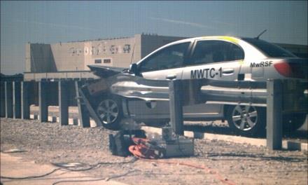
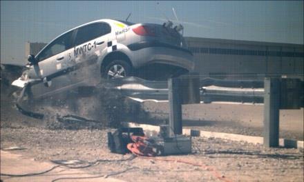
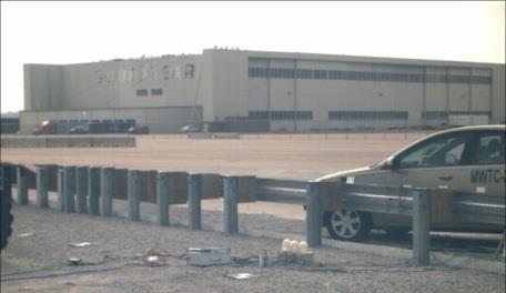
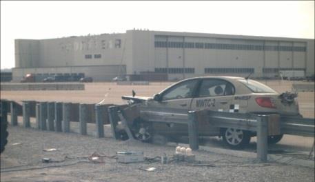
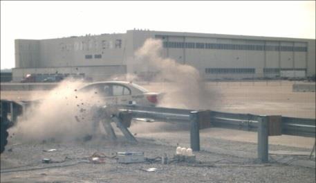
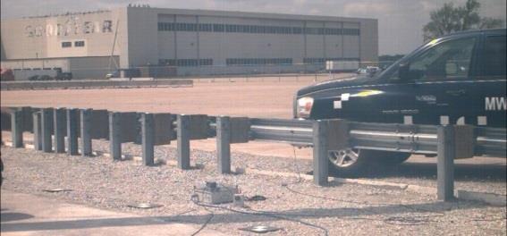
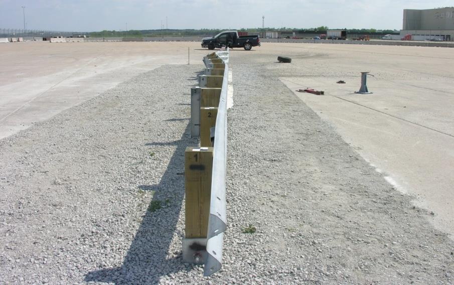
4 Rosenbaugh, Schmidt, and Faller PRELIMINARY DESIGN The full-scale crash test installation utilized the same guardrail transition installation (including upstream stiffness transition, downstream transition, and bridge rail) that was previously evaluated according to MASH. Only this time, a -in. tall curb was placed below the guardrail. The test installation was. ft long, as shown in Figure, which consisted of five major structural components: ) a -ft -in. long thrie beam and channel bridge railing system; ) ft in. of nested -gauge thrie beam guardrail; ) ft in. of standard -gauge thrie beam guardrail; ) a -ft -in. long, asymmetrical 0-gauge W- to-thrie transition segment; and ) 0 ft of standard -gauge W-beam rail attached to a simulated anchorage device. All rails had a top height of in., and the lap-splice connections between adjacent rail sections were configured to reduce vehicle snag at the splices. The guardrail components were supported by two BCT timber posts, steel guardrail posts, and three steel bridge posts. Post nos. and were BCT posts placed in -ft long steel foundation tubes to anchor the system. Post nos. through were standard -ft long Wx. guardrail posts with -in. deep wood blockouts. Post nos. through were -ft long Wx posts with -in. deep wood blockouts. The steel posts were placed at various spacings, as shown in Figure. The transition was installed within a compacted crushed limestone soil that met AASHTO Grade B gradation specifications and the soil strength requirements of MASH. The transition system s downstream end was connected to a thrie beam and channel bridge railing. Bridge post nos. through were Wx0 steel sections measuring ⅝ in. long. The bridge posts were rigidly attached to the concrete tarmac located at the MwRSF s outdoor proving grounds. A -in. tall triangular shaped curb was selected for use with this system since it is one of the more common curbs used in transition systems. The system was installed with the toe of the curb flush with the back face of the guardrail, as shown in Figure. The curb extended from ½ in. upstream from post no. until ¾ in. downstream from post no.. No soil backfill was installed behind the curb. This was considered a worst case scenario for inducing wheel snag on the curb and vehicle instabilities. Further design details of the system are shown in the test report by Winkelbauer et al. (). FULL-SCALE CRASH TEST NO. MWTC- The 00C vehicle impacted the MGS to thrie beam stiffness transition with curb at a speed of. mph and at an angle of.0 degrees. Initial vehicle impact was targeted for ¾ in. upstream of the W-to-thrie transition segment, which was selected to maximize the potential for the small car to wedge underneath the transition segment. The same impact point was utilized in previous testing (-). The actual point of impact was in. upstream of the target impact location. A summary of the test results and sequential photographs are shown in Figures and. The car s front bumper began to underride the guardrail upon impact, and the left-front tire overrode the curb. At 0.0 sec after impact, the car began to pitch downward, and at 0.0 sec, the front bumper impacted post no.. At 0. sec, the W-beam guardrail ruptured at the splice between the W-beam and W-to-thrie transition segment, located at post no.. Subsequently, the vehicle stopped redirecting and began impacting the guardrail posts head-on. The vehicle stopped moving downstream by 0. sec after impact, but pitched downward over degrees bringing the rear tires above the top of the guardrail. The vehicle eventually came to rest in front of post no. (. ft downstream of impact) and was facing the barrier. The vehicle trajectory and final position are shown in Figure.
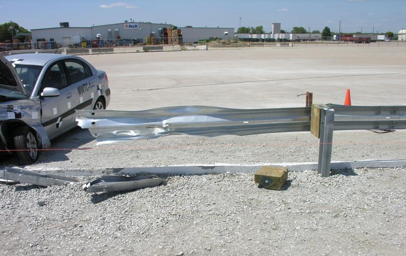
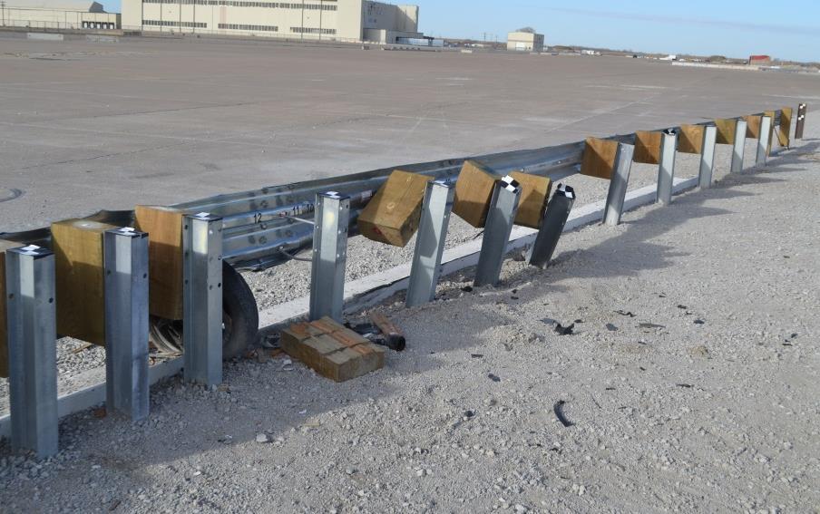
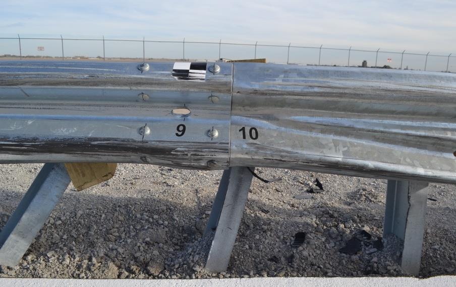
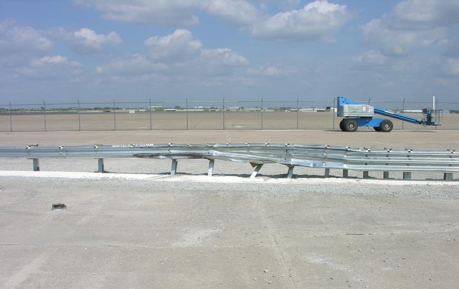
5 Rosenbaugh, Schmidt, and Faller 0 0 Damage to the barrier was severe, as shown in Figure. The rail was kinked and flattened throughout the impact region, while post nos. through were bent and twisted. The -gauge W-beam rail ruptured at the splice at post no. with all bolts remaining on the downstream end of the ruptured rail, or on the 0 gauge W-to-thrie transition element. The guardrail tore from the top, downstream corner of the splice diagonally to the bottom, upstream corner. The downstream edge of the W-beam remained attached to the W-to-thrie transition segment. The downstream end of rail folded back and behind the system at post no.. Additionally, a ½-in. vertical tear occurred in the thrie beam at the bottom post bolt of post no.. Finally, the top of the curb was gouged in several places from contact with the vehicle bumper and undercarriage. The damage to the vehicle was moderate with most of the damage occurring on the left side of the vehicle. The left fender, radiator, and headlight were all crushed inward, and the leftfront tire was torn. The front bumper and bumper cover were dented and disengaged, the leftfront corner of the hood folded under, and the engine cover split. Also, minor spider web cracking occurred in the lower-left corner of the windshield. The calculated occupant impact velocities (OIVs) and maximum 0.00-sec occupant ridedown accelerations (ORAs) in both the longitudinal and lateral directions are shown in Figure. Note that the OIVs were within the suggested limits provided in MASH, but the longitudinal ORA values exceeded the MASH limits. The measured occupant compartment deformations were all within MASH limits. Due to the w-beam rail rupturing, the loss of vehicle containment, and the excessive ORA values recorded by the accelerometers, test no. MWTC- on the MGS to thrie beam stiffness transition with curb was determined to be unacceptable according to the MASH safety performance criteria for test designation no. -0. More comprehensive test results are detailed in the test report by Winkelbauer et al. ().
6 FIGURE System details, test no. MWTC-. Rosenbaugh, Schmidt, and Faller


7 Rosenbaugh, Schmidt, and Faller sec 0.0 sec 0. sec 0. sec 0.0 sec Test Agency...MwRSF Test Number... MWTC- Date... /0/ MASH Test Designation Test Article... MGS Stiffness Transition with Curb Total Length.... ft Height to Top of Rail... in. Steel gauge W-Beam Guardrail Segment Location - Single... Post nos. to Steel 0 gauge W-Beam to Thrie Beam Transition Segment Location... Post nos. to Steel gauge Thrie Beam Guardrail Segment Location - Single... Post nos. to and to Segment Location - Nested... Post nos. to Guardrail Posts Post Nos in. long, BCT timber posts Post Nos in. long, Wx. Post Nos in. long, Wx Post Nos ⅝ in. long, Wx0 Post Spacing Post Nos. -, -... in. Post Nos. -, -... ½ in. Post Nos ¾ in. Soil Type... AASHTO Grade B Vehicle Make and Model Kia Rio Test Inertial..., lb Gross Static..., lb Curb..., lb Impact Conditions Speed.... mph Angle....0 deg Impact Severity (IS)...0 kip-ft >.0 kip-ft Impact Location... ¾ in. downstream of post no. Exit Conditions Speed... NA Angle... NA Exit Box Criterion... NA FIGURE Summary of test results, test no. MWTC Vehicle Stability... Satisfactory Vehicle Stopping Distance.... ft downstream of impact. ft laterally in front of system Vehicle Damage... Moderate VDS ()... -LFQ- CDC ()... -LFEW Maximum Interior Deformation... ¾ in. Test Article Damage... Severe (rail ruptured) Maximum Test Article Deflections Permanent Set... NA (rail ruptured) Dynamic... NA (rail ruptured) Working Width... NA (rail ruptured) Maximum Angular Displacements Roll.... < Pitch...-. < Yaw Transducer Data Transducer MASH Evaluation Criteria DTS DTS SLICE EDR- Limit OIV Longitudinal ft/s Lateral ORA g s Longitudinal Lateral THIV ft/s.. NA Not required PHD g s.. NA Not required ASI... Not required


8 Rosenbaugh, Schmidt, and Faller sec 0.0 sec 0.0 sec 0.0 sec 0. sec 0.0 sec FIGURE Sequential photos and system damage, test no. MWTC-.
9 Rosenbaugh, Schmidt, and Faller 0 0 MODIFICATIONS AND DESIGN DETAILS During test no. MWTC-, components of the small car penetrated under the W-beam rail, while the wheel climbed up and overrode the curb, compressing the suspension. These events led to heavy upward and lateral vehicle loading to the guardrail near the splice between the W-beam and W-to-thrie transition segment. The vehicle bumper impacting posts as it traveled through this region of the transition further increased the loads applied to the guardrail elements of this splice. Eventually, the W-beam rail ruptured at the splice location, gave way, and allowed the vehicle to snag on a stiff rail element in combination with several exposed transition posts. The presence of a curb under the MGS to thrie beam stiffness transition likely changed the load direction and magnitude applied to the guardrail in advance of the splice location. In addition, the presence of a curb may also have provided increased soil confinement and/or resistance to post-soil rotation within the guardrail region in advance of the splice location. The wheel interaction with the top and back side edge of the curb may have contributed to an-altered vehicle trajectory from that observed in the successful 00C test on the system without a curb. One or more of these factors, likely led to the W-beam rupture at the splice to the W-to-thrie transition element. Since the presence of a curb within the transition caused increased loading to the guardrail segments and lead to rail rupture, design modifications were required to strengthen the rail upstream of the W-to-thrie transition element. Thus, an additional -gauge W-beam segment was incorporated into the system such that. ft of nested W-beam guardrail preceded the 0-gauge W-to-thrie transition segment. This minor modification was believed to be sufficient to prevent rail rupture observed during a small car impact just upstream from the asymmetrical element and in combination with a concrete curb. Design details for test nos. MWTC- and MWTC- are shown in Figure. The system layouts for these two tests are nearly identical to that of test no. MWTC- with only the addition of the. ft nested W-beam section prior to the W-to-thrie transition segment.
10 FIGURE System layout, test nos. MWTC- and MWTC-. Rosenbaugh, Schmidt, and Faller 0
11 Rosenbaugh, Schmidt, and Faller FULL-SCALE CRASH TEST NO. MWTC- The 00C vehicle impacted the MGS to thrie beam stiffness transition with curb at a speed of. mph and at an angle of. degrees. Initial vehicle impact was targeted for ¾ in. upstream of the W-to-thrie transition segment, same as the previous test. The actual point of impact was in. of the targeted location. A summary of the test results and sequential photographs are shown in Figures and. Upon impact, the left-front corner of the vehicle underrode the rail, and the vehicle pitched down. The left-front tire proceeded to override the curb, and contact post nos. and. This time, the rail and splices held together and contained the vehicle as it continued to contact posts within the system. The vehicle was eventually redirected and exited the system 0. sec after impact at an angle of degrees. The vehicle came to rest.0 ft downstream of impact and. ft laterally in front of the system. The vehicle trajectory and final position are shown in Figure. Damage to the barrier was moderate, as shown in Figure. The guardrail was kinked and flattened throughout the impact region, and the rail disengaged from post nos. through 0. Post nos. through were bent back and downstream. The top of the curb had spalling between post nos. and. The maximum lateral dynamic post and barrier deflections were. in. at post no. and. in. at post no., respectively. The working width of the system was found to be. in. The majority of the vehicle damage was concentrated on the left-front corner and left side of the vehicle where the impact occurred. The left-front tire was deflated, disengaged, and came to rest adjacent to post no.. The left-front fender was crushed inward and pushed under the hood. Gouging was found on the fender, the left-front door, and the hood. Finally, the front bumper disengaged from the left side of the vehicle. The calculated OIVs and ORAs in both the longitudinal and lateral directions were within the suggested limits provided in MASH, as shown in Figure. Also, deformations to the occupant compartment were minor. Therefore, test no. MWTC-, conducted on the MGS to thrie beam stiffness transition with curb, was determined to be acceptable according to the MASH safety performance criteria for test designation no. -0. More comprehensive test results are detailed in the test report by Winkelbauer et al. ().


.")
... -LFQ CDC ().")

12 Rosenbaugh, Schmidt, and Faller sec 0. sec 0. sec 0. sec 0. sec Test Agency...MwRSF Test Number... MWTC- Date... /0/ MASH Test Designation Test Article... MGS Stiffness Transition with Curb Total Length.... ft Height to Top of Rail... in. Steel gauge W-Beam Guardrail Segment Location - Single... Post no. to Splice / Segment Location - Nested... Splice / to Post no. Steel 0 gauge W-Beam to Thrie Beam Transition Segment Location... Post nos. to Steel gauge Thrie Beam Guardrail Segment Location - Single... Post nos. to and to Segment Location - Nested... Post nos. to Guardrail Posts Post Nos in. long, BCT timber posts Post Nos in. long, Wx. Post Nos in. long, Wx Post Nos ⅝ in. long, Wx0 Post Spacing Post Nos. -, -... in. Post Nos. -, -... ½ in. Post Nos ¾ in. Soil Type... AASHTO Grade B Vehicle Make and Model Kia Rio Test Inertial...,0 lb Gross Static..., lb Curb...,0 lb Impact Conditions Speed.... mph Angle.... deg Impact Severity (IS)... kip-ft >.0 kip-ft Impact Location... ¼ in. downstream of post no. Exit Conditions Speed.... mph Angle....0 deg Exit Box Criterion... Passed FIGURE Summary of test results, test no. MWTC Vehicle Stability... Satisfactory Vehicle Stopping Distance....0 ft downstream of impact.... ft laterally in front of system Vehicle Damage... Moderate VDS ()... -LFQ CDC ()... -LFEW Maximum Interior Deformation... in. Test Article Damage... Moderate Maximum Test Article Deflections Permanent Set.... in. Dynamic.... in. Working Width.... in. Maximum Angular Displacements Roll...-. < Pitch...-. < Yaw Transducer Data Transducer MASH Evaluation Criteria DTS DTS SLICE EDR- Limit OIV ft/s ORA g s Longitudinal Lateral... 0 Longitudinal Lateral THIV ft/s.. NA Not required PHD g s.. NA Not required ASI..0. Not required


13 Rosenbaugh, Schmidt, and Faller sec 0.0 sec 0. sec 0.0 sec 0. sec 0. sec FIGURE Sequential photos and system damage, test no. MWTC-.
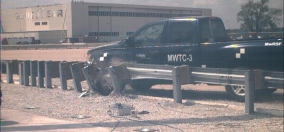
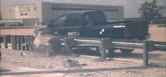
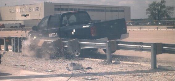
14 Rosenbaugh, Schmidt, and Faller FULL-SCALE CRASH TEST NO. MWTC- The 0P pickup impacted the MGS to thrie beam transition with curb at a speed of.0 mph and at an angle of. degrees. The vehicle impacted the target impact point at in. upstream of the W-to-thrie transition element. This impact point was identical to previous testing of the transition without curb and was selected to maximize the potential for pocketing, snag on guardrail posts, and loading to the transition element (-). A summary of the test results and sequential photographs are shown in Figures and. Upon impact, post nos. through 0 began deflecting backward. The left-front tire overrode the curb 0.0 sec after impact and underrode the guardrail 0.00 sec after impact. The tire then contacted post no. and detached from the vehicle. The posts and the rail continued to deflect backward as the vehicle was captured and redirected. The vehicle became parallel to the system at 0. sec and exited the system 0. sec after impact at an angle of degrees. The vehicle came to rest 0 ft directly downstream of impact. The vehicle trajectory and final position are shown in Figure. Damage to the barrier was moderate, as shown in Figure. The guardrail was kinked and flattened throughout the impact region and disengaged from post nos.,, and 0 through. Post nos. through were bent back and downstream. The maximum lateral dynamic post and rail deflections were. in. and.0 in., respectively, at post no. 0. The working width of the system was found to be 0. in. The damage to the vehicle was concentrated on the left-front corner and left side of the vehicle where impact occurred. The left-front bumper and quarter panel was deflected inward, and the left-front wheel was disengaged from the vehicle. The left-front door was dented, and the left side of the windshield had spider-web cracking. The calculated OIVs and ORAs in both the longitudinal and lateral directions were within the suggested limits provided in MASH and are shown in Figure. Also, deformations to the occupant compartment were minor. Therefore, test no. MWTC-, conducted on the MGS to thrie beam stiffness transition with curb, was determined to be acceptable according to the MASH safety performance criteria for test designation no. -. More comprehensive test results are detailed in the test report by Winkelbauer et al. ().


15 Rosenbaugh, Schmidt, and Faller sec 0.0 sec 0.0 sec 0.0 sec 0. sec Test Agency...MwRSF Test Number... MWTC- Date... // MASH Test Designation... - Test Article... MGS Stiffness Transition with Curb Total Length.... ft Height to Top of Rail... in. Steel gauge W-Beam Guardrail Segment Location - Single... Post no. to Splice / Segment Location - Nested... Splice / to Post no. Steel 0 gauge W-Beam to Thrie Beam Transition Segment Location... Post nos. to Steel gauge Thrie Beam Guardrail Segment Location - Single... Post nos. to and to Segment Location - Nested... Post nos. to Guardrail Posts Post Nos in. long, BCT timber posts Post Nos in. long, Wx Post Nos in. long, Wx Post Nos ⅝ in. long, Wx0 Post Spacing Post Nos. -, -... in. Post Nos. -, -... ½ in. Post Nos ¾ in. Soil Type... AASHTO Grade B Vehicle Make and Model...00 Dodge Ram 00 Quad Cab Test Inertial..., lb Gross Static..., lb Curb..., lb Impact Conditions Speed....0 mph Angle.... deg. Impact Severity kip-ft > 0. kip-ft Impact Location... in. Upstream of Post No. Exit Conditions Speed.... mph Angle.... deg. Exit Box Criterion... Passed FIGURE Summary of test results, test no. MWTC Vehicle Stability... Satisfactory Vehicle Stopping Distance... 0 ft downstream of impact... ft laterally behind system Vehicle Damage... Moderate VDS ()... -LFQ CDC ()... -LFEW Maximum Interior Deformation... ½ in. Test Article Damage... Moderate Maximum Test Article Deflections Permanent Set.... in. Dynamic.... in. Working Width in. Maximum Angular Displacements Roll...-. < Pitch < Yaw.... Transducer Data Transducer MASH Evaluation Criteria DTS DTS SLICE DTS Limit OIV Longitudinal ft/s Lateral... 0 ORA g s Longitudinal Lateral THIV ft/s.0. NA Not required PHD g s.. NA Not required ASI Not required


16 Rosenbaugh, Schmidt, and Faller sec 0.0 sec 0. sec 0. sec 0. sec 0. sec FIGURE Sequential photos and system damage, test no. MWTC-.
17 Rosenbaugh, Schmidt, and Faller SUMMARY AND CONCLUSIONS The objective of this study was to evaluate the MGS stiffness transition between W-beam guardrail and thrie beam approach transitions with a -in. tall curb. In 00, the stiffness transition configuration, shown in Figure a, was successfully crash tested without a curb (-). However, when a -in. tall curb was present with that system, the front end of the 00C vehicle penetrated under the W-beam rail at the same time that the wheel climbed up and overrode the curb. The combination of these events caused both upward and lateral loads being imparted to the rail elements which eventually caused the W-beam rail to rupture at the splice adjacent to the W-to-thrie transition element. The loss of containment led to the vehicle impacting transition posts head on causing ORA values above the MASH limits. Therefore, the previously tested MGS stiffness transition was not acceptable for use with curbs. After the failed crash test, the design was modified to incorporate an additional -gauge W-beam segment such that. ft of nested guardrail preceded the asymmetric W-to-thrie transition element. Subsequently, MASH test designation -0 was repeated, and the 00C small car was safely contained and redirected. A second test was then conducted on the modified transition according to MASH test designation -, and the 0P pickup truck was also safely contained and redirected. Upon the successful completion of the MASH TL- testing matrix, the modified upstream stiffness transition (between the MGS and thrie beam approach guardrail transition) with curb was found to satisfy current safety standards Since a very stiff thrie beam approach guardrail transition was used in the full-scale crash testing program, the upstream stiffness transition developed herein should be applicable to most other thrie beam approach guardrail transition systems. Details concerning the attachment of the upstream stiffness transition to other thrie beam transition systems can be found in the 00 report on the original development of the stiffness transition (). The use of nested W-beam rail at the upstream end of the W-to-thrie transition segment will be required for transition installations that utilize lower curbs. The use of nested rail was shown to sufficiently increase the strength of the system and prevent rail tearing. Additionally, rail nesting adjacent to the upstream end of the transition element aided to decrease vehicle pocketing and snag. These same benefits could also be gained if the modified (nested) version of the upstream stiffness transition was utilized for installations without curbs. Thus, system installations without curbs have the option to use either the original MGS stiffness transition design or the modified (nested) MGS stiffness transition. The final configurations of the stiffness transitions with and without a curb are shown in Figure. Although the W-beam to thrie beam stiffness transition (upstream portion of a full approach transition) evaluated herein can be utilized with or without a curb, many of the thrie beam approach transitions (downstream portions of a full transition system that attach to rigid parapets or bridge rails) are sensitive to the use of curbs. As described earlier, the addition or removal of a curb under the downstream end of a transition has been shown to greatly affect the safety performance of transitions during full-scale crash testing, sometimes to the extent of passing or failing the test criteria. As such, care should be taken to only utilize curbs with guardrail transition systems that have been developed, tested, and approved for use with curbs. The rail tearing and failure observed in test no. MWTC- may have implications for guardrail installations over curbs beyond this stiffness transition system. To date, -in. high W- beam guardrail systems in combination with curbs have only been evaluated in full-scale testing with large pickups. It is possible that small car impacts on other -in. high W-beam systems installed over curbs could impart similar combined lateral and vertical loads to the rail elements
18 Rosenbaugh, Schmidt, and Faller and result in similar rail tearing. Therefore, further evaluation of small car impacts into -in. high W-beam systems in combination with curbs may be warranted. (a) 0 0 (b) FIGURE MGS to thrie beam stiffness transitions details (a) without a curb and (b) with or without a curb, -in maximum curb height INSTALLATION RECOMMENDATIONS In order to ensure the safety performance of the transition, the -in. tall curb should be placed through the entire length of the stiffness transition. Thus, the curb should be extended from the bridge and through the nested W-beam section before either being terminated or transitioning to another curb type. Additionally, it is recommended to utilize a minimum length of ft for any curb shape transitions or terminations (e.g. transitioning from -in. curb to no curb). The curb was installed above ground line and without additional soil backfill. Thus, the ground surface underneath and behind the barrier remained level with the roadway surface and not the top of curb. This configuration was selected as a critical test design as it allows vehicle wheels to snag or catch on the backside of the curb, thus potentially leading to increased propensity for vehicle instabilities or wheel/bumper snag on strong posts. However, if the soil
19 Rosenbaugh, Schmidt, and Faller behind the curb was backfilled to match the height of the curb, the extra in. of soil backfill would result in increased post embedment, increased post-soil resistance, and a slightly stiffer and stronger barrier system. Impacts into the stiffened transition system would likely result in reduced lateral barrier displacements and less vehicle snag. Thus, it is believed that installations utilizing soil backfill would also perform acceptably. The tested system had ft. in. of standard MGS between the upstream end of the stiffness transition (nested rail segments) and the upstream BCT wood anchor post. Guardrail end terminals are designed, crash tested, and evaluated for use when directly attached to semirigid W-beam guardrail systems, instead of stiffer approach guardrail transitions. The introduction of stiffer (nested) rail segments may potentially lead to degraded performance of crashworthy terminals. Additionally, placement of the upstream end anchorage too close to the stiffness transition may negatively affect system performance and potentially result in excessive barrier deflections, vehicle pocketing, wheel snagging on posts, vehicle-to-barrier override, or other vehicle instabilities. Thus, the following implementation guidelines should be considered when utilizing the modified MGS stiffness transition. Although the reference point was changed to the upstream end of the nested rail segment, these recommendations result in the same system lengths upstream of the W-to-thrie transition segment that were recommended previously for the original transition system design without nesting ().. The length of W-beam guardrail installed upstream of the nested W-beam section is recommended to be greater than or equal to the total system length of an acceptable TL- guardrail end terminal. Thus, the guardrail terminal s interior end (identified by stroke length) should not intrude into the nested W-beam section of the modified MGS stiffness transition.. A recommended minimum barrier length of ft ½ in. is to be installed beyond the upstream end of the nested W-beam section, which includes standard MGS, a crashworthy guardrail end terminal, and an acceptable anchorage system.. For flared guardrail applications, a minimum length of. ft is recommended between the upstream end of the nested W-beam section and the start of the flared section (i.e. bend between flare and tangent sections). The MGS stiffness transition with curb was successfully crash tested with all posts installed in level terrain. Therefore, this upstream stiffness transition (and all other guardrail transitions tested on level terrain) should be implemented with a minimum of ft of level or gently-sloped fill placed behind the posts, unless special design provisions are made to account for decreased post-soil resistance. Additionally, it is unknown as to whether a non-blocked version of the MGS installed adjacent to the new stiffness transition will negatively affect the system. The safety performance of non-blocked MGS in conjunction with the modified stiffness transition can only be verified through the use of full-scale crash testing. As such, it is recommended that a minimum of. ft of standard MGS with spacer blocks be placed adjacent to the modified stiffness transition (upstream end of the nested rail section) prior to transitioning to a non-blocked, -in. tall, W-beam guardrail system. ACKNOWLEDGMENTS The authors wish to acknowledge several sources that made a contribution to this project: () the Midwest States Regional Pooled Fund Program; () MwRSF personnel for constructing the
20 Rosenbaugh, Schmidt, and Faller barriers and conducting the crash tests; and () IMH Products, Inc. for assistance with the asymmetric W-to-thrie transition element. REFERENCES. Rosenbaugh, S.K., Faller, R.K., Bielenberg, R.W., Lechtenberg, K.A., Sicking, D.L., Reid, J.D., Development of the MGS Approach Guardrail Transition Using Standardized Steel Posts, Final Report to the Midwest States Regional Pooled Fund Program, Report No. TRP , Midwest Roadside Safety Facility, University of Nebraska-Lincoln, Lincoln, NE, December 0, 00.. Lechtenberg, K.A., Rosenbaugh, S.K., Bielenberg, R.W., Mongiardini, M., Faller, R.K., Albuquerque, F.D.B., Development and Implementation of the Simplified Midwest Guardrail System Stiffness Transition, Transportation Research Record No. 0, Transportation Research Board, Washington, D.C., 0.. Manual for Assessing Safety Hardware, American Association of State Highway and Transportation Officials (AASHTO), Washington, D.C., 00. Ross, H.E., D.L. Sicking, R.A. Zimmer, and J.D. Michie. Recommended Procedures for the Safety Performance Evaluation of Highway Features. National Cooperative Highway Research Program Report 0, Transportation Research Board of the National Academies,.. Faller, R.K., Reid, J.D., Rohde, J.R., Sicking, D.L., and Keller, E.A. Two Approach Guardrail Transitions for Concrete Safety Shape Barriers, Final Report to the Midwest States Regional Pooled Fund Program, Report No. TRP-0--, Midwest Roadside Safety Facility, University of Nebraska-Lincoln, Lincoln, NE, May,.. Bligh, R.P., Menges, W.L, and Haug, R.P, Evaluation of Guardrail to Concrete Bridge Rail Transitions, Final Report to the Texas Department of Transportation, Report no. FHWA/TX- 0/-, Texas Transportation Institute, Texas A&M University, College Station, TX, October 00.. Polivka, K.A., Faller, R.K., Sicking, D.L., Rohde, J.R., Bielenberg, R.W., Reid, J.D., and Coon, B.A., Performance Evaluation of the Guardrail to Concrete Barrier Transition Update to NCHRP 0 Test No. - with C.G. Height (T-), Final Report to the National Cooperative Highway Research Program, Report No. TRP-0--0, Midwest Roadside Safety Facility, University of Nebraska-Lincoln, Lincoln, NE October, 00.. Williams, W.F., Bligh, R.P., and Menges, W.L., MASH TL- Testing and Evaluation of the TXDOT TRC Bridge Rail Transition, Report no. FHWA/TX-/-00--, Texas Transportation Institute, Texas A&M University, College Station, TX, March 0.. D.C. Alberson, W.L. Menges, and Schoeneman, S.K., NCHRP Report 0 Test - on the Ohio Type Transition from Thrie Beam to Concrete Parapet with Asphalt Curb, 00-, Texas Transportation Institute, Texas A&M University, College Station, TX, August D.C. Alberson, W.L. Menges, and Haug R.R., NCHRP Report 0 Test - of the Ohio Transition at the 0-Gauge Non-Symmetrical Type Transition Section, 00-, Texas Transportation Institute, Texas A&M University, College Station, TX, April 00.. Winkelbauer, B.J., Putjenter, J.G., Rosenbaugh, S.K., Lechtenberg, K.A., Bielenberg, R.W., Faller, R.K., and Reid, J.D., Dynamic Evaluation of MGS Stiffness Transition with Curb, Final Report to the Midwest States Regional Pooled Fund Program, Transportation Research Report No. TRP-0--, Midwest Roadside Safety Facility, University of Nebraska- Lincoln, Lincoln, NE, June 0, 0.
21 Rosenbaugh, Schmidt, and Faller. Vehicle Damage Scale for Traffic Investigators, Second Edition, Technical Bulletin No., Traffic Accident Data (TAD) Project, National Safety Council, Chicago, Illinois,.. Collision Deformation Classification Recommended Practice J March 0, Handbook Volume, Society of Automotive Engineers (SAE), Warrendale, Pennsylvania,.
Evaluation of the Midwest Guardrail System stiffness transition with curb
 University of Nebraska - Lincoln DigitalCommons@University of Nebraska - Lincoln Civil Engineering Faculty Publications Civil Engineering 2016 Evaluation of the Midwest Guardrail System stiffness transition
DEVELOPMENT OF A MASH TL-3 TRANSITION BETWEEN GUARDRAIL AND PORTABLE CONCRETE BARRIERS
 Duplication for publication or sale is strictly prohibited without prior written permission of the Transportation Research Board Paper No. 17-01712 DEVELOPMENT OF A MASH TL-3 TRANSITION BETWEEN GUARDRAIL
Midwest Guardrail System Without Blockouts
 Duplication for publication or sale is strictly prohibited without prior written permission of the Transportation Research Board Paper No. 13-0418 Midwest Guardrail System Without Blockouts by John D.
A MASH Compliant W-Beam Median Guardrail System
 0 0 0 0 0 A MASH Compliant W-Beam Median Guardrail System By A. Y. Abu-Odeh, R. P. Bligh, W. Odell, A. Meza, and W. L. Menges Submitted: July 0, 0 Word Count:, + ( figures + tables=,000) =, words Authors:
MINIMUM EFFECTIVE LENGTH FOR THE MIDWEST GUARDRAIL SYSTEM
 Duplication for publication or sale is strictly prohibited without prior written permission of the Transportation Research Board Paper No. 15-0484 MINIMUM EFFECTIVE LENGTH FOR THE MIDWEST GUARDRAIL SYSTEM
Development and Implementation of the Simplified MGS Stiffness Transition
 Duplication for publication or sale is strictly prohibited without prior written permission of the Transportation Research Board Paper No. 12-3367 Development and Implementation of the Simplified MGS Stiffness
Advances in Simulating Corrugated Beam Barriers under Vehicular Impact
 13 th International LS-DYNA Users Conference Session: Automotive Advances in Simulating Corrugated Beam Barriers under Vehicular Impact Akram Abu-Odeh Texas A&M Transportation Institute Abstract W-beam
PERFORMANCE EVALUATION OF THE MODIFIED G4(1S) GUARDRAIL UPDATE TO NCHRP 350 TEST NO WITH 28" C.G. HEIGHT (2214WB-2)
 GUARDRAIL UPDATE TO NCHRP 350 TEST NO WITH 28 C.G. HEIGHT (2214WB-2)") PERFORMANCE EVALUATION OF THE MODIFIED G4(1S) GUARDRAIL UPDATE TO NCHRP 350 TEST NO. 3-11 WITH 28" C.G. HEIGHT (2214WB-2) Submitted by Karla A. Polivka, M.S.M.E., E.I.T. Research Associate Engineer Dean
PERFORMANCE EVALUATION OF THE MODIFIED G4(1S) GUARDRAIL UPDATE TO NCHRP 350 TEST NO. 3-11 WITH 28" C.G. HEIGHT (2214WB-2) Submitted by Karla A. Polivka, M.S.M.E., E.I.T. Research Associate Engineer Dean
DEVELOPMENT OF A TRANSITION BETWEEN FREE-STANDING AND REDUCED-DEFLECTION PORTABLE CONCRETE BARRIERS PHASE I
 Research Project Number TPF-5(193) Supplement #78 DEVELOPMENT OF A TRANSITION BETWEEN FREE-STANDING AND REDUCED-DEFLECTION PORTABLE CONCRETE BARRIERS PHASE I Submitted by Mojdeh Asadollahi Pajouh, Ph.D.
EXTENDING TL-2 SHORT-RADIUS GUARDRAIL TO LARGER RADII
 Research Project Number TPF-5(193) Supplement 27 EXTENDING TL-2 SHORT-RADIUS GUARDRAIL TO LARGER RADII Submitted by Cody S. Stolle, Ph.D., E.I.T. Post-Doctoral Research Associate Robert W. Bielenberg,
1962: HRCS Circular 482 one-page document, specified vehicle mass, impact speed, and approach angle for crash tests.
 1 2 3 1962: HRCS Circular 482 one-page document, specified vehicle mass, impact speed, and approach angle for crash tests. 1973: NCHRP Report 153 16-page document, based on technical input from 70+ individuals
PERFORMANCE EVALUATION OF THE FREE-STANDING TEMPORARY BARRIER UPDATE TO NCHRP 350 TEST NO (2214TB-1)
") PERFORMANCE EVALUATION OF THE FREE-STANDING TEMPORARY BARRIER UPDATE TO NCHRP 350 TEST NO. 3-11 (2214TB-1) Submitted by Karla A. Polivka, M.S.M.E., E.I.T. Research Associate Engineer Dean L. Sicking, Ph.D.,
PERFORMANCE EVALUATION OF THE FREE-STANDING TEMPORARY BARRIER UPDATE TO NCHRP 350 TEST NO. 3-11 (2214TB-1) Submitted by Karla A. Polivka, M.S.M.E., E.I.T. Research Associate Engineer Dean L. Sicking, Ph.D.,
AASHTO Manual for Assessing Safety Hardware, AASHTO/FHWA Joint Implementation Plan Standing Committee on Highways September 24, 2015
 AASHTO Manual for Assessing Safety Hardware, 2015 AASHTO/FHWA Joint Implementation Plan Standing Committee on Highways September 24, 2015 Full Scale MASH Crash Tests (NCHRP 22-14(02)) Conducted several
MASH TEST 3-10 ON 31-INCH W-BEAM GUARDRAIL WITH STANDARD OFFSET BLOCKS
 TTI: 9-1002 MASH TEST 3-10 ON 31-INCH W-BEAM GUARDRAIL WITH STANDARD OFFSET BLOCKS ISO 17025 Laboratory Testing Certificate # 2821.01 Crash testing performed at: TTI Proving Ground 3100 SH 47, Building
PERFORMANCE EVALUATION OF THE FREE-STANDING TEMPORARY BARRIER UPDATE TO NCHRP 350 TEST NO WITH 28" C.G. HEIGHT (2214TB-2)
") PERFORMANCE EVALUATION OF THE FREE-STANDING TEMPORARY BARRIER UPDATE TO NCHRP 350 TEST NO. 3-11 WITH 28" C.G. HEIGHT (2214TB-2) Submitted by Karla A. Polivka, M.S.M.E., E.I.T. Research Associate Engineer
PERFORMANCE EVALUATION OF THE FREE-STANDING TEMPORARY BARRIER UPDATE TO NCHRP 350 TEST NO. 3-11 WITH 28" C.G. HEIGHT (2214TB-2) Submitted by Karla A. Polivka, M.S.M.E., E.I.T. Research Associate Engineer
PERFORMANCE EVALUATION OF THE PERMANENT NEW JERSEY SAFETY SHAPE BARRIER UPDATE TO NCHRP 350 TEST NO (2214NJ-2)
") PERFORMANCE EVALUATION OF THE PERMANENT NEW JERSEY SAFETY SHAPE BARRIER UPDATE TO NCHRP 350 TEST NO. 4-12 (2214NJ-2) Submitted by Karla A. Polivka, M.S.M.E., E.I.T. Research Associate Engineer Dean L.
PERFORMANCE EVALUATION OF THE PERMANENT NEW JERSEY SAFETY SHAPE BARRIER UPDATE TO NCHRP 350 TEST NO. 4-12 (2214NJ-2) Submitted by Karla A. Polivka, M.S.M.E., E.I.T. Research Associate Engineer Dean L.
Evaluation and Design of ODOT s Type 5 Guardrail with Tubular Backup
 Evaluation and Design of ODOT s Type 5 Guardrail with Tubular Backup Draft Final Report Chuck A. Plaxico, Ph.D. James C. Kennedy, Jr., Ph.D. Charles R. Miele, P.E. for the Ohio Department of Transportation
VERIFICATION & VALIDATION REPORT of MGS Barrier Impact with 1100C Vehicle Using Toyota Yaris Coarse FE Model
 VERIFICATION & VALIDATION REPORT of MGS Barrier Impact with 1100C Vehicle Using Toyota Yaris Coarse FE Model CCSA VALIDATION/VERIFICATION REPORT Page 1 of 4 Project: CCSA Longitudinal Barriers on Curved,
CRITICAL FLARE RATES FOR W-BEAM GUARDRAIL DETERMINING MAXIMUM CAPACITY USING COMPUTER SIMULATION NCHRP 17-20(3)
") CRITICAL FLARE RATES FOR W-BEAM GUARDRAIL DETERMINING MAXIMUM CAPACITY USING COMPUTER SIMULATION NCHRP 17-2(3) Submitted by Beau D. Kuipers, B.S.M.E., E.I.T. Graduate Research Assistant Ronald K. Faller,
CRITICAL FLARE RATES FOR W-BEAM GUARDRAIL DETERMINING MAXIMUM CAPACITY USING COMPUTER SIMULATION NCHRP 17-2(3) Submitted by Beau D. Kuipers, B.S.M.E., E.I.T. Graduate Research Assistant Ronald K. Faller,
SGR52 TOP-MOUNTED WEAK-POST GUARDRAIL ATTACHED TO CULVERT PLAN VIEW ELEVATION VIEW DETAIL B DETAIL A SHEET NO. DATE: 37 1/2" 953 (TYP) 150" 3810
 150 3810") PLAN VIEW C 150" 3810 37 1/2" 953 (TYP) A B C 8-FBB01 RWB01a FWR01 RWM04a FWR01 RWB01a RWM04a PSF01 FBX08a PSF01 FBX08a DETAIL A DETAIL B 1 of 7 12/5/2016 INTENDED USE The Top-Mounted Weak-Post Guardrail
PLAN VIEW C 150" 3810 37 1/2" 953 (TYP) A B C 8-FBB01 RWB01a FWR01 RWM04a FWR01 RWB01a RWM04a PSF01 FBX08a PSF01 FBX08a DETAIL A DETAIL B 1 of 7 12/5/2016 INTENDED USE The Top-Mounted Weak-Post Guardrail
SAFETY PERFORMANCE OF WORK-ZONE DEVICES UNDER MASH TESTING
 SAFETY PERFORMANCE OF WORK-ZONE DEVICES UNDER MASH TESTING Schmidt, Faller, Lechtenberg, Sicking, Holloway Midwest Roadside Safety Facility Nebraska Transportation Center University of Nebraska-Lincoln
DEFLECTION LIMITS FOR TEMPORARY CONCRETE BARRIERS
 Midwest State s Regional Pooled Fund Research Program Fiscal Year 1998-1999 (Year 9) NDOR Research Project Number SPR-3(017) DEFLECTION LIMITS FOR TEMPORARY CONCRETE BARRIERS Submitted by Dean L. Sicking,
INCREASED SPAN LENGTH FOR THE MGS LONG-SPAN GUARDRAIL SYSTEM PART III: FAILURE ANALYSIS
 Midwest States Pooled Fund Research Program Fiscal Years 2013 (Years 23) Research Project Number TPF-5(193) Supplement #56 NDOR Sponsoring Agency Code RPFP-13-MGS-3 INCREASED SPAN LENGTH FOR THE MGS LONG-SPAN
SUMMARY CHANGES FOR NCHRP REPORT 350 GUIDELINES [NCHRP (02)] Keith A. Cota, Chairman Technical Committee on Roadside Safety June 14, 2007
![SUMMARY CHANGES FOR NCHRP REPORT 350 GUIDELINES [NCHRP (02)] Keith A. Cota, Chairman Technical Committee on Roadside Safety June 14, 2007](/thumbs/87/97351925.jpg "SUMMARY CHANGES FOR NCHRP REPORT 350 GUIDELINES [NCHRP (02)] Keith A. Cota, Chairman Technical Committee on Roadside Safety June 14, 2007") SUMMARY CHANGES FOR NCHRP REPORT 350 GUIDELINES [NCHRP 22-14 (02)] Keith A. Cota, Chairman Technical Committee on Roadside Safety June 14, 2007 BACKGROUND Circular 482 (1962) First full scale crash test
SUMMARY CHANGES FOR NCHRP REPORT 350 GUIDELINES [NCHRP 22-14 (02)] Keith A. Cota, Chairman Technical Committee on Roadside Safety June 14, 2007 BACKGROUND Circular 482 (1962) First full scale crash test
Assessing Options for Improving Roadside Barrier Crashworthiness
 13 th International LS-DYNA Users Conference Session: Simulation Assessing Options for Improving Roadside Barrier Crashworthiness D. Marzougui, C.D. Kan, and K.S. Opiela Center for Collision Safety and
Manual for Assessing Safety Hardware
 American Association of State Highway and Transportation Officials Manual for Assessing Safety Hardware 2009 vii PREFACE Effective traffic barrier systems, end treatments, crash cushions, breakaway devices,
COMPARISON OF THE IMPACT PERFORMANCE OF THE G4(1W) AND G4(2W) GUARDRAIL SYSTEMS UNDER NCHRP REPORT 350 TEST 3-11 CONDITIONS
 AND G4(2W) GUARDRAIL SYSTEMS UNDER NCHRP REPORT 350 TEST 3-11 CONDITIONS") Paper No. 00-0525 COMPARISON OF THE IMPACT PERFORMANCE OF THE G4(1W) AND G4(2W) GUARDRAIL SYSTEMS UNDER NCHRP REPORT 350 TEST 3-11 CONDITIONS by Chuck A. Plaxico Associate Research Engineer Worcester Polytechnic
Paper No. 00-0525 COMPARISON OF THE IMPACT PERFORMANCE OF THE G4(1W) AND G4(2W) GUARDRAIL SYSTEMS UNDER NCHRP REPORT 350 TEST 3-11 CONDITIONS by Chuck A. Plaxico Associate Research Engineer Worcester Polytechnic
Form DOT F (8-72) Texas Transportation Institute The Texas A&M University System College Station, Texas
 Texas Transportation Institute The Texas A&M University System College Station, Texas") 1. Report No. FHWA/TX-02/4162-1 Technical Report Documentation Page 2. Government Accession No. 3. Recipient's Catalog No. 4. Title and Subtitle EVALUATION OF TEXAS GRID-SLOT PORTABLE CONCRETE BARRIER
1. Report No. FHWA/TX-02/4162-1 Technical Report Documentation Page 2. Government Accession No. 3. Recipient's Catalog No. 4. Title and Subtitle EVALUATION OF TEXAS GRID-SLOT PORTABLE CONCRETE BARRIER
Analysis of Existing Work-Zone Sign Supports Using Manual for Assessing Safety Hardware Safety Performance Criteria
 University of Nebraska - Lincoln DigitalCommons@University of Nebraska - Lincoln Civil Engineering Faculty Publications Civil Engineering 2011 Analysis of Existing Work-Zone Sign Supports Using Manual
CRASH TEST AND EVALUATION OF 3-FT MOUNTING HEIGHT SIGN SUPPORT SYSTEM
 TTI: 9-1002-15 CRASH TEST AND EVALUATION OF 3-FT MOUNTING HEIGHT SIGN SUPPORT SYSTEM ISO 17025 Laboratory Testing Certificate # 2821.01 Crash testing performed at: TTI Proving Ground 3100 SH 47, Building
Research Project Number SPR-P1(13)M326 DEVELOPMENT OF A MASH TL-3 TRANSITION BETWEEN GUARDRAIL AND PORTABLE CONCRETE BARRIERS.
M326 DEVELOPMENT OF A MASH TL-3 TRANSITION BETWEEN GUARDRAIL AND PORTABLE CONCRETE BARRIERS.") Research Project Number SPR-P1(13)M326 DEVELOPMENT OF A MASH TL-3 TRANSITION BETWEEN GUARDRAIL AND PORTABLE CONCRETE BARRIERS Submitted by David A. Gutierrez, B.S.C.E., E.I.T. Graduate Research Assistant
Research Project Number SPR-P1(13)M326 DEVELOPMENT OF A MASH TL-3 TRANSITION BETWEEN GUARDRAIL AND PORTABLE CONCRETE BARRIERS Submitted by David A. Gutierrez, B.S.C.E., E.I.T. Graduate Research Assistant
Evaluation of Barriers for Very High Speed Roadways
 TTI: 0-6071 Evaluation of Barriers for Very High Speed Roadways ISO 17025 Laboratory Testing Certificate # 2821.01 Crash testing performed at: TTI Proving Ground 3100 SH 47, Building 7091 Bryan, TX 77807
Development of Combination Pedestrian-Traffic Bridge Railings
 TRANSPORTATION RESEARCH RECORD 1468 41 Development of Combination Pedestrian-Traffic Bridge Railings D. LANCE BULLARD, JR., WANDA L. MENGES, AND C. EUGENE BUTH Two bridge railing designs have been developed
MASH TEST 3-37 OF THE TxDOT 31-INCH W-BEAM DOWNSTREAM ANCHOR TERMINAL
 TTI: 9-1002 MASH TEST 3-37 OF THE TxDOT 31-INCH W-BEAM DOWNSTREAM ANCHOR TERMINAL ISO 17025 Laboratory Testing Certificate # 2821.01 Crash testing performed at: TTI Proving Ground 3100 SH 47, Building
MASH Test 3-11 on the T131RC Bridge Rail
 TTI: 9-1002-12 MASH Test 3-11 on the T131RC Bridge Rail ISO 17025 Laboratory Testing Certificate # 2821.01 Crash testing performed at: TTI Proving Ground 3100 SH 47, Building 7091 Bryan, TX 77807 Test
VULCAN BARRIER TL-3 GENERAL SPECIFICATIONS
 VULCAN BARRIER TL-3 GENERAL SPECIFICATIONS I. GENERAL A. The VULCAN BARRIER TL-3 (VULCAN TL-3) shall be a highly portable and crashworthy longitudinal barrier especially suited for use as a temporary barrier
Texas Transportation Institute The Texas A&M University System College Station, Texas
 1. Report No. FHWA/TX-04/9-8132-1 4. Title and Subtitle TESTING AND EVALUATION OF THE FLORIDA JERSEY SAFETY SHAPED BRIDGE RAIL 2. Government Accession No. 3. Recipient's Catalog No. 5. Report Date February
Texas Transportation Institute The Texas A&M University System College Station, Texas
 1. Report No. FHWA/TX-05/9-8132-P7 4. Title and Subtitle TL-4 CRASH TESTING OF THE F411 BRIDGE RAIL 2. Government Accession No. 3. Recipient's Catalog No. 5. Report Date October 2004 Technical Report Documentation
Crash Testing Growth Common Roadside Hardware Systems Draft FHWA and AASHTO Requirements for Implementing MASH 2015
 64 th Annual Illinois Traffic Safety and Engineering Conference October 14, 2015 Crash Testing Growth Common Roadside Hardware Systems Draft FHWA and AASHTO Requirements for Implementing MASH 2015 1 https://www.youtube.com/watch?feature
Development and Validation of a Finite Element Model of an Energy-absorbing Guardrail End Terminal
 Development and Validation of a Finite Element Model of an Energy-absorbing Guardrail End Terminal Yunzhu Meng 1, Costin Untaroiu 1 1 Department of Biomedical Engineering and Virginia Tech, Blacksburg,
MASH 2016 Implementation: What, When and Why
 MASH 2016 Implementation: What, When and Why Roger P. Bligh, Ph.D., P.E. Senior Research Engineer Texas A&M Transportation Institute June 7, 2016 2016 Traffic Safety Conference College Station, Texas Outline
June 5, In Reply Refer To: HSSD/B-178. Mr. Kevin K. Groeneweg Mobile Barriers LLC Genesee Trail Road Golden, CO Dear Mr.
 June 5, 2008 1200 New Jersey Avenue, SE. Washington, DC 20590 In Reply Refer To: HSSD/B-178 Mr. Kevin K. Groeneweg Mobile Barriers LLC 24918 Genesee Trail Road Golden, CO 80401 Dear Mr. Groeneweg: This
Sponsored by Roadside Safety Research Program Pooled Fund Study No. TPF-5(114)
") Proving Ground Test Report No. 405160-23-2 Test Report Date: February 2012 MASH TEST 3-11 OF THE W-BEAM GUARDRAIL ON LOW-FILL BOX CULVERT by William F. Williams, P.E. Associate Research Engineer and Wanda
Proving Ground Test Report No. 405160-23-2 Test Report Date: February 2012 MASH TEST 3-11 OF THE W-BEAM GUARDRAIL ON LOW-FILL BOX CULVERT by William F. Williams, P.E. Associate Research Engineer and Wanda
NCHRP Report 350 Test 4-12 of the Modified Thrie Beam Guardrail
 NCHRP Report 350 Test 4-12 of the Modified Thrie Beam Guardrail PUBLICATION NO. FHWA-RD-99-065 DECEMBER 1999 Research, Development, and Technology Turner-Fairbank Highway Research Center 6300 Georgetown
July 10, Refer to: HSA-10/CC-78A
 July 10, 2003 Refer to: HSA-10/CC-78A Barry D. Stephens, P.E. Senior Vice President of Engineering ENERGY ABSORPTION Systems, Inc. 3617 Cincinnati Avenue Rocklin, California 95765 Dear Mr. Stephens: Your
MASH TEST 3-21 ON TL-3 THRIE BEAM TRANSITION WITHOUT CURB
 TTI: 9-1002-12 MASH TEST 3-21 ON TL-3 THRIE BEAM TRANSITION WITHOUT CURB ISO 17025 Laboratory Testing Certificate # 2821.01 Crash testing performed at: TTI Proving Ground 3100 SH 47, Building 7091 Bryan,
W-Beam Guiderail Transition from Light to Heavy Posts
 TRANSPORTATION RESEARCH RECORD 1198 55 W-Beam Guiderail Transition from Light to Heavy Posts DONALD G. HERRING AND JAMES E. BRYDEN Two full-scale crash tests evaluated a transition between lightand heavy-post
TEST MATRICES FOR EVALUATING CABLE MEDIAN BARRIERS PLACED IN V-DITCHES
 Midwest States Regional Pooled Fund Research Program Fiscal Year 2012 (Year 22) Research Project Number TPF-5(193) Supplement #44 NDOR Sponsoring Agency Code RPFP-12-CABLE1&2 TEST MATRICES FOR EVALUATING
VULCAN BARRIER TL-3 GENERAL SPECIFICATIONS
 VULCAN BARRIER TL-3 GENERAL SPECIFICATIONS I. GENERAL A. The VULCAN BARRIER TL-3 (VULCAN TL-3) shall be a highly portable and crashworthy longitudinal barrier especially suited for use as a temporary barrier
NCHRP Report 350 Crash Testing and Evaluation of the S-Square Mailbox System
 TTI: 0-5210 NCHRP Report 350 Crash Testing and Evaluation of the S-Square Mailbox System ISO 17025 Laboratory Testing Certificate # 2821.01 Crash testing performed at: TTI Proving Ground 3100 SH 47, Building
W-Beam Approach Treatment at Bridge Rail Ends Near Intersecting Roadways
 TRANSPORTATION RESEARCH RECORD 1133 51 W-Beam Approach Treatment at Bridge Rail Ends Near Intersecting Roadways M. E. BRONSTAD, M. H. RAY, J. B. MAYER, JR., AND c. F. MCDEVITT This paper is concerned with
Texas Transportation Institute The Texas A&M University System College Station, Texas
 1. Report No. FHWA/TX-07/0-5527-1 4. Title and Subtitle DEVELOPMENT OF A LOW-PROFILE TO F-SHAPE TRANSITION BARRIER SEGMENT 2. Government Accession No. 3. Recipient's Catalog No. Technical Report Documentation
STI Project: Barrier Systems, Inc. RTS-QMB Longitudinal Barrier. Page 38 of 40 QBOR1. Appendix F (Continued) Figure F-3
 Figure F-3") Barrier Systems, Inc. RTS-QMB Longitudinal Barrier STI Project: QBOR1 Page 38 of 40 Appendix F (Continued) Figure F-3 t=.500sec 115 meters overall 37.1 Impact Severity (kj).. 141.6 Angle (deg).. 25 Speed
Barrier Systems, Inc. RTS-QMB Longitudinal Barrier STI Project: QBOR1 Page 38 of 40 Appendix F (Continued) Figure F-3 t=.500sec 115 meters overall 37.1 Impact Severity (kj).. 141.6 Angle (deg).. 25 Speed
BarrierGate. General Specifications. Manual Operations General Specifications
 BarrierGate General Specifications Manual Operations General Specifications BarrierGate GENERAL SPECIFICATIONS I. GENERAL A. The BarrierGate system (the gate) shall be designed and manufactured by Energy
METAL BEAM GUARDFENCE TRANSITION AND END TREATMENT IDENTIFICATION GUIDE
 2016 TxDOT Design Division METAL BEAM GUARDFENCE TRANSITION AND END TREATMENT IDENTIFICATION GUIDE A guide to help TxDOT employees identify metal beam guardfence transitions and end treatments for the
MASH TEST 3-11 OF THE TxDOT T222 BRIDGE RAIL
 TTI: 9-1002-12 MASH TEST 3-11 OF THE TxDOT T222 BRIDGE RAIL ISO 17025 Laboratory Testing Certificate # 2821.01 Crash testing performed at: TTI Proving Ground 3100 SH 47, Building 7091 Bryan, TX 77807 Test
GUARDRAIL TESTING MODIFIED ECCENTRIC LOADER TERMINAL (MELT) AT NCHRP 350 TL-2. Dean C. Alberson, Wanda L. Menges, and Rebecca R.
 AT NCHRP 350 TL-2. Dean C. Alberson, Wanda L. Menges, and Rebecca R.") GUARDRAIL TESTING MODIFIED ECCENTRIC LOADER TERMINAL (MELT) AT NCHRP 350 TL-2 Dean C. Alberson, Wanda L. Menges, and Rebecca R. Haug Prepared for The New England Transportation Consortium July 2002 NETCR
GUARDRAIL TESTING MODIFIED ECCENTRIC LOADER TERMINAL (MELT) AT NCHRP 350 TL-2 Dean C. Alberson, Wanda L. Menges, and Rebecca R. Haug Prepared for The New England Transportation Consortium July 2002 NETCR
Illinois Safety Program IDOT District ATSSA Workshop
 Illinois Safety Program IDOT District ATSSA Workshop Roadway Departure & MASH DRAFT IDOT Facilitator: Dave Piper ATSSA Facilitator: Jim Thonn 1 Illinois Emphasis Area Priority Pyramid 2 Fatalities and
February 8, In Reply Refer To: HSSD/CC-104
 February 8, 2008 200 New Jersey Avenue, SE. Washington, DC 20590 In Reply Refer To: HSSD/CC-04 Barry D. Stephens, P.E. Sr. Vice President Engineering Energy Absorption Systems, Inc. 367 Cincinnati Avenue
Sponsored by Roadside Safety Research Program Pooled Fund Study
 Proving Ground Report No. 405160-10 Report Date: August 2010 EVALUATION OF EXISTING T-INTERSECTION GUARDRAIL SYSTEMS FOR EQUIVALENCY WITH NCHRP REPORT 350 TL-2 TEST CONDITIONS by Akram Y. Abu-Odeh Associate
Continued Development of a Non-Proprietary, High-Tension, Cable End Terminal System
 University of Nebraska - Lincoln DigitalCommons@University of Nebraska - Lincoln Nebraska Department of Transportation Research Reports Nebraska LTAP 4-29-2016 Continued Development of a Non-Proprietary,
MASH08 TEST 3-11 OF THE ROCKINGHAM PRECAST CONCRETE BARRIER
 Proving Ground Report No. 400001-RPC4 Report Date: July 2009 MASH08 TEST 3-11 OF THE ROCKINGHAM PRECAST CONCRETE BARRIER by C. Eugene Buth, P.E. Research Engineer William F. Williams, P.E. Assistant Research
Implementation of AASHTO s Manual for Assessing Safety Hardware (MASH) 2016
 2016") Implementation of AASHTO s Manual for Assessing Safety Hardware (MASH) 2016 Update from the Technical Committee on Roadside Safety Keith Cota, New Hampshire DOT MASH 2016 Overview Background Ballot Results/Dates
Implementation of AASHTO s Manual for Assessing Safety Hardware (MASH) 2016 Update from the Technical Committee on Roadside Safety Keith Cota, New Hampshire DOT MASH 2016 Overview Background Ballot Results/Dates
Crash Performance of Strong-Post W-Beam Guardrail with Missing Blockouts Carolyn E. Hampton and Hampton C. Gabler
 Crash Performance of Strong-Post W-Beam Guardrail with Missing Blockouts Carolyn E. Hampton and Hampton C. Gabler Virginia Tech Center for Injury Biomechanics, Blacksburg VA 24061 Abstract Missing blockouts
MASH TEST 3-11 OF THE TxDOT SINGLE SLOPE BRIDGE RAIL (TYPE SSTR) ON PAN-FORMED BRIDGE DECK
 ON PAN-FORMED BRIDGE DECK") TTI: 9-1002 MASH TEST 3-11 OF THE TxDOT SINGLE SLOPE BRIDGE RAIL (TYPE SSTR) ON PAN-FORMED BRIDGE DECK ISO 17025 Laboratory Testing Certificate # 2821.01 Crash testing performed at: TTI Proving Ground
TTI: 9-1002 MASH TEST 3-11 OF THE TxDOT SINGLE SLOPE BRIDGE RAIL (TYPE SSTR) ON PAN-FORMED BRIDGE DECK ISO 17025 Laboratory Testing Certificate # 2821.01 Crash testing performed at: TTI Proving Ground
Product Specification. ABSORB 350 TM TL-2 Non-Redirective, Gating, Crash Cushion Applied to Quickchange Moveable Barrier
 TB 000612 Rev. 0 Page 1 of 9 Product Specification ABSORB 350 TM TL-2 Non-Redirective, Gating, Crash Cushion Applied to Quickchange Moveable Barrier I. General The ABSORB 350 TM TL-2 System is a Non-Redirective,
Slotted Rail Guardrail Terminal
 TRANSPORTATION RESEARCH RECORD 1500 43 Slotted Rail Guardrail Terminal KING K. MAK, ROGER P. BLIGH, HAYES E. Ross, JR., AND DEAN L. SICKING A slotted rail terminal (SRT) for W-beam guardrails was successfully
CRASH TESTING OF RSA/K&C ANTI-RAM FOUNDATION BOLLARD PAD IN ACCORDANCE WITH U.S. DEPARTMENT OF STATE DIPLOMATIC SECURITY SD-STD-02.
 CRASH TESTING OF RSA/K&C ANTI-RAM FOUNDATION BOLLARD PAD IN ACCORDANCE WITH U.S. DEPARTMENT OF STATE DIPLOMATIC SECURITY SD-STD-02.01 REVISION A Prepared for RSA Protective Technologies, LLC FINAL REPORT
PR V2. Submitted by. Professor MIDWEST Vine Street (402) Submitted to
 Submitted to") FINAL REPORT PR4893118-V2 ZONE OF INTRUSION STUDY Submitted by John D. Reid, Ph.D. Professor Dean L.. Sicking, Ph.D., P.E. Professorr and MwRSF Director MIDWEST ROADSIDE SAFETY FACILITY University of Nebraska-Lincoln
FINAL REPORT PR4893118-V2 ZONE OF INTRUSION STUDY Submitted by John D. Reid, Ph.D. Professor Dean L.. Sicking, Ph.D., P.E. Professorr and MwRSF Director MIDWEST ROADSIDE SAFETY FACILITY University of Nebraska-Lincoln
Performance Level 1 Bridge Railings
 80 TRANSPORTATION RESEARCH RECORD 1500 Performance Level 1 Bridge Railings DEAN C. ALBERSON, WANDA L. MENGES, AND C. EUGENE BUTH Twenty-three states, FHW A, and the District of Columbia sponsored the project
CRASH TEST AND EVALUATION OF TEMPORARY WOOD SIGN SUPPORT SYSTEM FOR LARGE GUIDE SIGNS
 TTI: 9-1002-15 CRASH TEST AND EVALUATION OF TEMPORARY WOOD SIGN SUPPORT SYSTEM FOR LARGE GUIDE SIGNS ISO 17025 Laboratory Testing Certificate # 2821.01 Crash testing performed at: TTI Proving Ground 3100
CRASH TESTING AND EVALUATION OF WORK ZONE TRAFFIC CONTROL DEVICES
 Paper No. 980627 CRASH TESTING AND EVALUATION OF WORK ZONE TRAFFIC CONTROL DEVICES by King K. Mak Phone: 210-698-2068 Fax: 210-698-2068 e-mail: king@tti3a.tamu.edu Texas Transportation Institute The Texas
Technical Report Documentation Page 2. Government Accession No. 3. Recipient's Catalog No. 1. Report No. FHWA/TX-09/
 1. Report No. FHWA/TX-09/0-6071-1 4. Title and Subtitle ANALYSIS OF ROADSIDE SAFETY DEVICES FOR USE ON VERY HIGH-SPEED ROADWAYS Technical Report Documentation Page 2. Government Accession No. 3. Recipient's
INCREASED SPAN LENGTH FOR THE MGS LONG-SPAN GUARDRAIL SYSTEM
 University of Nebraska - Lincoln DigitalCommons@University of Nebraska - Lincoln Mechanical (and Materials) Engineering -- Dissertations, Theses, and Student Research Mechanical & Materials Engineering,
Technical Report Documentation Page Form DOT F (8-72) Reproduction of completed page authorized
 Reproduction of completed page authorized") 1. Report No. FHWA/TX-05/0-4162-3 4. Title and Subtitle 2. Government Accession No. 3. Recipient's Catalog No. DEVELOPMENT OF LOW-DEFLECTION PRECAST CONCRETE ARRIER 5. Report Date January 2005 Technical
1. Report No. FHWA/TX-05/0-4162-3 4. Title and Subtitle 2. Government Accession No. 3. Recipient's Catalog No. DEVELOPMENT OF LOW-DEFLECTION PRECAST CONCRETE ARRIER 5. Report Date January 2005 Technical
Development of a Slotted-Rail Breakaway Cable Terminal
 TRANSPORTATION RESEA RCH RECORD 1233 65 Development of a Slotted-Rail Breakaway Cable Terminal DEAN L. SICKING, ASIF B. QuRESHY, AND HAYES E. Ross, JR. Development of the Slotted-Rail Breakaway Cable Terminal
EVALUATING THE RELEVANCY OF CURRENT CRASH TEST GUIDELINES FOR ROADSIDE SAFETY BARRIERS ON HIGH SPEED ROADS
 EVALUATING THE RELEVANCY OF CURRENT CRASH TEST GUIDELINES FOR ROADSIDE SAFETY BARRIERS ON HIGH SPEED ROADS CONNIE XAVIER DOMINIQUE LORD, PH.D. Zachry Department of Civil Engineering, Texas A&M University
TEXAS TRANSPORTATION INSTITUTE THE TEXAS A & M UNIVERSITY SYSTEM COLLEGE STATION, TEXAS 77843
 NCHRP REPORT 350 ASSESSMENT OF EXISTING ROADSIDE SAFETY HARDWARE by C. Eugene Buth, P.E. Senior Research Engineer Wanda L. Menges Associate Research Specialist and Sandra K. Schoeneman Research Associate
Guide Rail Safety Symposium
 Ministry of Transportation Guide Rail Safety Symposium MTO Provincial Roadside Safety Update Mark C. Ayton, P. Eng. Senior Engineer, Highway Design MTO Highway Standards Branch MTO Provincial Roadside
Texas Transportation Institute The Texas A&M University System College Station, Texas
 2. Government Accession No. 3. Recipient's Catalog No. 1. Report No. FHWA/TX-03/0-4138-3 4. Title and Subtitle PERFORMANCE OF THE TXDOT T202 (MOD) BRIDGE RAIL REINFORCED WITH FIBER REINFORCED POLYMER BARS
TEXAS TRANSPORTATION INSTITUTE THE TEXAS A & M UNIVERSITY SYSTEM COLLEGE STATION, TEXAS 77843
 NCHRP REPORT 350 TEST 3-11 OF THE STEEL-BACKED TIMBER GUARDRAIL by D. Lance Bullard, Jr., P.E. Associate Research Engineer Wanda L. Menges Associate Research Specialist and Sandra K. Schoeneman Research
Impact analysis of a vertical flared back bridge rail-to-guardrail transition structure using simulation
 Finite Elements in Analysis and Design 41 (2005) 371 396 www.elsevier.com/locate/finel Impact analysis of a vertical flared back bridge rail-to-guardrail transition structure using simulation Ali O. Atahan,
DEVELOPMENT OF A MASH TL-3 MEDIAN BARRIER GATE
 TTI: 9-1002 DEVELOPMENT OF A MASH TL-3 MEDIAN BARRIER GATE ISO 17025 Laboratory Testing Certificate # 2821.01 Crash testing performed at: TTI Proving Ground 3100 SH 47, Building 7091 Bryan, TX 77807 Research/Test
Virginia Department of Transportation
 TEST REPORT FOR: Virginia Department of Transportation SKT SP 350 50 (15.24 m) System PREPARED FOR: Virginia Department of Transportation 1401 E. Broad St. Richmond, VA 23219 TEST REPORT NUMBER: REPORT
Wyoming Road Closure Gate
 38 TRANSPORTATION RESEARCH RECORD 1528 Wyoming Road Closure Gate KING K. MAK, ROGER P. BLIGH, AND WILLIAM B. WILSON Road closure gates are used to close certain highways when driving conditions become
Universal TAU-IIR Redirective, Non-Gating, Crash Cushion
 TB 110927 Rev. 0 Page 1 of 5 Product Specification Universal TAU-IIR Redirective, Non-Gating, Crash Cushion I. General The Universal TAU-IIR system is a Redirective, Non-Gating Crash Cushion in accordance
Development of a TL-5 Vertical Faced Concrete Median Barrier Incorporating Head Ejection Criteria
 Midwest States Regional Pooled Fund Research Program Fiscal Year 2004-2005 (Year 15) Research Project Number SPR-3(017) NDOR Sponsoring Agency Code RPFP-05-01 Development of a TL-5 Vertical Faced Median
TEXAS TRANSPORTATION INSTITUTE THE TEXAS A & M UNIVERSITY SYSTEM COLLEGE STATION, TEXAS
 NCHRP REPORT 350 TEST 4-21 OF THE ALASKA MULTI-STATE BRIDGE RAIL THRIE-BEAM TRANSITION by C. Eugene Buth Senior Research Engineer William F. Williams Assistant Research Engineer Wanda L. Menges Associate
Crash Tests of a Retrofit Thrie Beam Bridge Rail and Transition
 TRANSPORTATION RESEARCH RECORD 1302 Crash Tests of a Retrofit Thrie Beam Bridge Rail and Transition DORAN L. GLAUZ, ROGER L. STOUGHTON, AND J. JAY FOLSOM Two crash tests each were performed on a Thrie
ROBUST PROJECT Norwegian Public Roads Administration / Force Technology Norway AS
 ROBUST PROJECT Norwegian Public Roads Administration / Force Technology Norway AS Evaluation of small car - RM_R1 - prepared by Politecnico di Milano Volume 1 of 1 January 2006 Doc. No.: ROBUST-5-002/TR-2004-0039
OPTIMIZATION OF THRIE BEAM TERMINAL END SHOE CONNECTION
 TTI: 9-1002-15 OPTIMIZATION OF THRIE BEAM TERMINAL END SHOE CONNECTION ISO 17025 Laboratory Testing Certificate # 2821.01 Pendulum testing performed at: TTI Proving Ground 3100 SH 47, Building 7091 Bryan,
ASTM F TEST M30 ON THE RSS-3000 DROP BEAM SYSTEM
 Proving Ground Test Report No.: 510602-RSS3 Test Report Date: January 2014 ASTM F2656-07 TEST M30 ON THE RSS-3000 DROP BEAM SYSTEM by Dean C. Alberson, Ph.D., P.E. Research Engineer Michael S. Brackin,
1200 New Jersey Ave., SE of Transportation Washington, D.C
 U.S. Department 1200 New Jersey Ave., SE of Transportation Washington, D.C. 20590 Federal Highway Administration Mr. Gerrit A. Dyke Lindsay Transportation Solutions, Inc. 180 River Road Rio Vista, CA 94571
Vehicle Crash Tests of Concrete Median Barrier Retrofitted with Slipformed Concrete Glare Screen
 TRANSPORTATION RESEARCH RECORD 1419 35 Vehicle Crash Tests of Concrete Median Barrier Retrofitted with Slipformed Concrete Glare Screen PAYAM RowHANI, DoRAN GLAuz, AND RoGER L. STOUGHTON Two vehicle crash
DISTRIBUTION: Electronic Recipients List TRANSMITTAL LETTER NO. (15-01) MINNESOTA DEPARTMENT OF TRANSPORTATION. MANUAL: Road Design English Manual
 MINNESOTA DEPARTMENT OF TRANSPORTATION. MANUAL: Road Design English Manual") DISTRIBUTION: Electronic Recipients List MINNESOTA DEPARTMENT OF TRANSPORTATION DEVELOPED BY: Design Standards Unit ISSUED BY: Office of Project Management and Technical Support TRANSMITTAL LETTER NO.
DISTRIBUTION: Electronic Recipients List MINNESOTA DEPARTMENT OF TRANSPORTATION DEVELOPED BY: Design Standards Unit ISSUED BY: Office of Project Management and Technical Support TRANSMITTAL LETTER NO.
Improving Roadside Safety by Computer Simulation
 A2A04:Committee on Roadside Safety Features Chairman: John F. Carney, III, Worcester Polytechnic Institute Improving Roadside Safety by Computer Simulation DEAN L. SICKING, University of Nebraska, Lincoln
PRODUCT DESCRIPTION. X-Tension DS. is suitable for all road types: Motorways, country roads, city streets for speed categories up to 110 km/h.
 INDEX Introduction 2 Product Description 3 Installation 6 Specifications 7 Crash Tests Table 8 Reusability 9 FAQ 10 Annexes 14 Drawings 15 Pictures 16 Crash Tests Results 18 Approvals 23 INTRODUCTION Improving
TRACC. Trinity Attenuating Crash Cushion
 TRACC Trinity Attenuating Crash Cushion CSP Pacific Business Unit of Fletcher Concrete & Infrastructure Limited 306 Neilson Street Onehunga, Auckland Phone: (09) 634 1239 or 0800 655 200 Fax: (09) 634
Appendix D. Figure D-1. ENCLOSURE 1 (4 Pages) SafeGuard TM Gate System
 SafeGuard TM Gate System") Appendix D Figure D-1 SafeGuard TM Gate System ENCLOSURE 1 (4 Pages) Appendix D (Continued) Figure D-4 SafeGuard TM Gate System Appendix D (Continued) Figure D-9 SafeGuardTM Gate System Page D-9 Figure
Appendix D Figure D-1 SafeGuard TM Gate System ENCLOSURE 1 (4 Pages) Appendix D (Continued) Figure D-4 SafeGuard TM Gate System Appendix D (Continued) Figure D-9 SafeGuardTM Gate System Page D-9 Figure
Evaluating The Relevancy Of Current Crash Test Guidelines For Roadside Safety Barriers On High Speed Roads
 Evaluating The Relevancy Of Current Crash Test Guidelines For Roadside Safety Barriers On High Speed Roads Connie Xavier Dominique Lord Chiara Dobrovolny Roger Bligh TRB 1 st International Roadside Safety