PERFORMANCE EVALUATION OF THE FREE-STANDING TEMPORARY BARRIER UPDATE TO NCHRP 350 TEST NO (2214TB-1)
|
|
|
- Clemence Palmer
- 6 years ago
- Views:
Transcription
1 PERFORMANCE EVALUATION OF THE FREE-STANDING TEMPORARY BARRIER UPDATE TO NCHRP 350 TEST NO (2214TB-1) Submitted by Karla A. Polivka, M.S.M.E., E.I.T. Research Associate Engineer Dean L. Sicking, Ph.D., P.E. Professor and MwRSF Director Bob W. Bielenberg, M.S.M.E., E.I.T. Research Associate Engineer Ronald K. Faller, Ph.D., P.E. Research Assistant Professor John R. Rohde, Ph.D., P.E. Associate Professor John D. Reid, Ph.D. Associate Professor Brian A. Coon, Ph.D., P.E. Research Associate Engineer MIDWEST ROADSIDE SAFETY FACILITY University of Nebraska-Lincoln 527 Nebraska Hall Lincoln, Nebraska (402) Submitted to NATIONAL COOPERATIVE HIGHWAY RESEARCH PROGRAM Transportation Research Board National Research Council 2101 Constitution Avenue, N.W. Washington, D.C MwRSF Research Report No. TRP October 11, 2006
2 1. Report No Recipient s Accession No. TRP Title and Subtitle 5. Report Date Technical Report Documentation Page Performance Evaluation of the Free-Standing Temporary Barrier Update to NCHRP 350 Test No (2214TB- 1) October 11, Author(s) 8. Performing Organization Report No. Polivka, K.A., Faller, R.K., Sicking, D.L., Rohde, J.R., Bielenberg, B.W., Reid, J.D., and Coon, B.A. TRP Performing Organization Name and Address 10. Project/Task/Work Unit No. Midwest Roadside Safety Facility (MwRSF) University of Nebraska-Lincoln 527 Nebraska Hall Lincoln, NE Contract or Grant (G) No. NCHRP 22-14(2) 12. Sponsoring Organization Name and Address 13. Type of Report and Period Covered National Cooperative Highway Research Program Transportation Research Board National Research Council 2101 Constitution Avenue, N.W. Washington, D.C Final Report Sponsoring Agency Code 15. Supplementary Notes Prepared in cooperation with U.S. Department of Transportation, Federal Highway Administration 16. Abstract (Limit: 200 words) Based on the proposed changes to the National Cooperative Highway Research Program (NCHRP) Report No. 350 guidelines, NCHRP Project 22-14(2) researchers deemed it appropriate to evaluate a freestanding temporary concrete barrier system prior to finalizing the new crash testing procedures and guidelines. For this effort, the free-standing temporary barrier system was selected for evaluation. One full-scale vehicle crash test was performed on the longitudinal barrier system in accordance with the Test Level 3 (TL-3) requirements presented in the Update to NCHRP Report No For the testing program, a 2270P pickup truck vehicle, which was a ¾-ton, two-door vehicle, was used. The free-standing temporary barrier system provided an acceptable safety performance when impacted by the ¾-ton, two-door pickup truck, thus meeting the proposed TL-3 requirements presented in the Update to NCHRP Report No This test vehicle was not ultimately recommended for inclusion in the Update to NCHRP Report No Document Analysis/Descriptors 18. Availability Statement Highway Safety, Roadside Appurtenances, Longitudinal Barriers, Temporary Barriers, Concrete Barriers, Crash Test, Compliance Test, NCHRP 350 Update No restrictions. Document available from: National Technical Information Services, Springfield, Virginia Security Class (this report) 20. Security Class (this page) 21. No. of Pages 22. Price Unclassified Unclassified 72
3 DISCLAIMER STATEMENT The contents of this report reflect the views of the authors who are responsible for the facts and the accuracy of the data presented herein. The contents do not necessarily reflect the official views nor policies of the National Research Council of the Transportation Research Board nor the Federal Highway Administration. This report does not constitute a standard, specification, or regulation. ii
4 ACKNOWLEDGMENTS The authors wish to acknowledge several sources that made a contribution to this project: (1) the National Research Council of the Transportation Research Board for sponsoring this project; and (2) MwRSF personnel for constructing the barrier and conducting the crash test. A special thanks is also given to the following individuals who made a contribution to the completion of this research project. Midwest Roadside Safety Facility J.C. Holloway, M.S.C.E., E.I.T., Research Manager C.L. Meyer, B.S.M.E., E.I.T., Research Engineer II A.T. Russell, B.S.B.A., Laboratory Mechanic II K.L. Krenk, B.S.M.A, Field Operations Manager A.T. McMaster, Laboratory Mechanic I Undergraduate and Graduate Assistants Transportation Research Board Charles W. Niessner, Senior Program Officer NCHRP 22-14(2) Panel Members Federal Highway Administration John Perry, P.E., Nebraska Division Office Danny Briggs, Nebraska Division Office Dunlap Photography James Dunlap, President and Owner iii
5 TABLE OF CONTENTS Page TECHNICAL REPORT DOCUMENTATION PAGE... i DISCLAIMER STATEMENT... ii ACKNOWLEDGMENTS... iii TABLE OF CONTENTS... iv List of Figures... vi List of Tables... viii 1 INTRODUCTION Problem Statement Objective Scope TEST REQUIREMENTS AND EVALUATION CRITERIA Test Requirements Evaluation Criteria TEST CONDITIONS Test Facility Vehicle Tow and Guidance System Test Vehicles Data Acquisition Systems Accelerometers Rate Transducers High-Speed Photography Pressure Tape Switches DESIGN DETAILS CRASH TEST Test 2214TB Test Description Barrier Damage Vehicle Damage Occupant Risk Values Discussion SUMMARY AND CONCLUSIONS...49 iv
6 7 REFERENCES APPENDICES...52 APPENDIX A - English-Unit System Drawings...53 APPENDIX B - Test Summary Sheet in English Units...59 APPENDIX C - Occupant Compartment Deformation Data, Test 2214TB APPENDIX D - Accelerometer and Rate Transducer Data Analysis, Test 2214TB v
7 List of Figures Page 1. Test Vehicle, Test 2214TB Vehicle Dimensions, Test 2214TB Vehicle Target Locations, Test 2214TB Location of High-Speed Cameras, Test 2214TB Layout for Free-Standing Temporary Temporary Barrier Design Details Temporary Barrier Profile Details Temporary Barrier Bill of Bars Temporary Barrier Connection Details Temporary Barrier System Temporary Barrier System Barrier Connection Joints Summary of Test Results and Sequential Photographs, Test 2214TB Additional Sequential Photographs, Test 2214TB Additional Sequential Photographs, Test 2214TB Additional Sequential Photographs, Test 2214TB Additional Sequential Photographs, Test 2214TB Documentary Photographs, Test 2214TB Documentary Photographs, Test 2214TB Impact Location, Test 2214TB Vehicle Final Position and Trajectory Marks, Test 2214TB Temporary Barrier Damage, Test 2214TB Temporary Barrier Damage, Test 2214TB Temporary Barrier Damage, Test 2214TB Temporary Barrier Damage, Test 2214TB Temporary Barrier Damage, Test 2214TB Vehicle Damage, Test 2214TB Vehicle Damage, Test 2214TB Vehicle Damage, Test 2214TB A-1. Layout for Free-Standing Temporary Barriers (English)...54 A-2. Temporary Barrier Design Details (English)...55 A-3. Temporary Barrier Profile Details (English)...56 A-4. Temporary Barrier Bill of Bars (English)...57 A-5. Temporary Barrier Connection Details (English)...58 B-1. Summary of Test Results and Sequential Photographs (English), Test 2214TB C-1. Occupant Compartment Deformation Data, Test 2214TB C-2. Occupant Compartment Deformation Index (OCDI), Test 2214TB C-3. NASS Crush Data, Test 2214TB D-1. Graph of Longitudinal Deceleration, Test 2214TB D-2. Graph of Longitudinal Occupant Impact Velocity, Test 2214TB D-3. Graph of Longitudinal Occupant Displacement, Test 2214TB vi
8 D-4. Graph of Lateral Deceleration, Test 2214TB D-5. Graph of Lateral Occupant Impact Velocity, Test 2214TB D-6. Graph of Lateral Occupant Displacement, Test 2214TB D-7. Graph of Yaw Angular Displacements, Test 2214TB vii
9 List of Tables Page 1. Update to NCHRP Report No. 350 Test Level 3 Crash Test Conditions Update to NCHRP Report No. 350 Evaluation Criteria for Crash Tests Summary of Safety Performance Evaluation Results...50 viii
10 1 INTRODUCTION 1.1 Problem Statement In the late 1990s, roadside safety experts, State DOT representatives, Federal government officials, and industry personnel began discussions and preparations for updating the National Cooperative Highway Research Program (NCHRP) Report No. 350 safety performance guidelines (1). The new guidelines would improve upon existing test procedures, consider changes in the vehicle fleet, provide criteria for new roadside hardware categories and re-evaluate the appropriateness of the impact conditions. In 1997, NCHRP Project 22-14, entitled Improvement of the Procedures for the Safety Performance Evaluation of Roadside Features, was initiated with the intent to: (1) evaluate the relevance and efficacy of the crash testing procedures, (2) assess the needs for updating NCHRP Report No. 350, and (3) provide recommended strategies for their implementation. Following the completion of this NCHRP study at the Texas Transportation Institute (TTI) in 2001, a follow-on research study was begun in NCHRP Project 22-14(2), entitled Improved Procedures for Safety Performance Evaluation of Roadside Features, was undertaken by Midwest Roadside Safety Facility (MwRSF) researchers with the objectives to: (1) prepare the revised crash testing guidelines, (2) assess the effects of any proposed guidelines, and (3) identify research needs for future improvements to the procedures. Consequently, it was anticipated that a number of revisions would be incorporated into the Update of NCHRP Report No. 350 guidelines (2). For example, changes in the vehicle fleet have resulted in the need to reassess the small car and pickup truck test vehicles. Accordingly, new, heavier test vehicles have been selected for both the small car and light truck classes of vehicles. 1
11 Additionally, during the second study, researchers determined that the 100 km/h (62.1 mph) impact speed and 25 degree impact angle would remain the same as used in NCHRP Report No. 350 for the large passenger vehicle class impacting longitudinal barriers. However, the impact angle for the small car impact condition would increase from 20 to 25 degrees for evaluating longitudinal barriers and the length-of-need for guardrail terminals. The effects of any changes to vehicle specifications or impact conditions must be understood before the safety performance evaluation guidelines are finalized. Therefore, a series of full-scale crash tests on NCHRP Report No. 350 approved systems were to be conducted with the new test vehicles and impact conditions. 1.2 Objective The objective of this research project was to evaluate the safety performance of the freestanding temporary barrier system when full-scale vehicle crash tested according to the test designation no criteria presented in the Update of NCHRP Report No. 350 guidelines (2). 1.3 Scope The research objective was achieved through the completion of several tasks. First, a fullscale vehicle crash test was performed on the free-standing temporary barrier system. The crash test utilized a pickup truck, weighing approximately 2,270 kg (5,004 lbs). The target impact conditions for the test were an impact speed of km/h (62.1 mph) and an impact angle of 25 degrees. Next, the test results were analyzed, evaluated, and documented. Finally, conclusions and recommendations were made that pertain to the safety performance of the free-standing temporary barrier system relative to the test performed. 2
12 2.1 Test Requirements 2 TEST REQUIREMENTS AND EVALUATION CRITERIA Historically, longitudinal barriers, such as temporary barrier systems, have been required to satisfy impact safety standards in order to be accepted by the Federal Highway Administration (FHWA) for use on National Highway System (NHS) construction projects or as a replacement for existing designs not meeting current safety standards. In recent years, these safety standards have consisted of the guidelines and procedures published in NCHRP Report No. 350 (1). However, NCHRP Project 22-14(2) generated revised testing procedures and guidelines for use in the evaluation of roadside safety appurtenances and were presented in the draft report entitled, NCHRP Report 350 Update (2). Therefore, according to Test Level 3 (TL-3) of the Update to NCHRP Report No. 350, longitudinal barrier systems must be subjected to two full-scale vehicle crash tests. The two full-scale crash tests are as follows: 1. Test Designation An 1,100-kg (2,425-lb) passenger car impacting at a nominal speed and angle of km/h (62.1 mph) and 25 degrees, respectively. 2. Test Designation A 2,270-kg (5,004-lb) pickup truck impacting at a nominal speed and angle of km/h (62.1 mph) and 25 degrees, respectively. The test conditions for TL-3 longitudinal barriers are summarized in Table 1. Test Designation 3-11 was conducted for the free-standing temporary barrier system described herein. 2.2 Evaluation Criteria According to the Update to NCHRP Report No. 350, the evaluation criteria for full-scale vehicle crash testing are based on three appraisal areas: (1) structural adequacy; (2) occupant risk; and (3) vehicle trajectory after collision. Criteria for structural adequacy are intended to evaluate the 3
13 ability of the barrier to contain, redirect, or allow controlled vehicle penetration in a predictable manner. Occupant risk evaluates the degree of hazard to occupants in the impacting vehicle. Vehicle trajectory after collision is a measure of the potential for the post-impact trajectory of the vehicle to cause subsequent multi-vehicle accidents. This criterion also indicates the potential safety hazard for the occupants of other vehicles or the occupants of the impacting vehicle when subjected secondary collisions with other fixed objects. These three evaluation criteria are summarized in Table 2 and defined in greater detail in the Update to NCHRP Report No. 350 report (2). The fullscale vehicle crash tests were conducted and reported in accordance with the procedures provided in the Update to NCHRP Report No Table 1. Update to NCHRP Report No. 350 Test Level 3 Crash Test Conditions Test Article Longitudinal Barrier Test Designation Test Vehicle (km/h) Impact Conditions Speed (mph) Angle (degrees) Evaluation Criteria C A,D,F,H,I,M P A,D,F,H,I,M 1 Evaluation criteria explained in Table 2. 4
14 Table 2. Update to NCHRP Report No. 350 Evaluation Criteria for Crash Tests Structural Adequacy Occupant Risk Vehicle Trajectory A. Test article should contain and redirect the vehicle or bring the vehicle to a controlled stop; the vehicle should not penetrate, underride, or override the installation although controlled lateral deflection of the test article is acceptable. D. Detached elements, fragments or other debris from the test article should not penetrate or show potential for penetrating the occupant compartment, or present an undue hazard to other traffic, pedestrians, or personnel in a work zone. Deformations of, or intrusions into, the occupant compartment should not exceed limits set forth in Section 5.3 and Appendix E of the Update to NCHRP Report No F. The vehicle should remain upright during and after collision. H. Longitudinal and lateral occupant impact velocities should fall below the preferred value of 9.0 m/s (29.5 ft/s), or at least below the maximum allowable value of 12.0 m/s (39.4 ft/s). I. Longitudinal and lateral occupant ridedown accelerations should fall below the preferred value of 15 Gs, or at least below the maximum allowable value of 20.0 Gs. M. After impact, the vehicle shall exit the barrier within the exit box. 5
15 3 TEST CONDITIONS 3.1 Test Facility The testing facility is located at the Lincoln Air Park on the northwest side of the Lincoln Municipal Airport and is approximately 8.0 km (5 mi.) northwest of the University of Nebraska- Lincoln. 3.2 Vehicle Tow and Guidance System A reverse cable tow system with a 1:2 mechanical advantage was used to propel the test vehicle. The distance traveled and the speed of the tow vehicle were one-half that of the test vehicle. The test vehicle was released from the tow cable before impact with the barrier system. A digital speedometer was located on the tow vehicle to increase the accuracy of the test vehicle impact speed. A vehicle guidance system developed by Hinch (3) was used to steer the test vehicle. A guide-flag, attached to the front-right wheel and the guide cable, was sheared off before impact with the barrier system. The 9.5-mm (0.375-in.) diameter guide cable was tensioned to approximately 15.6 kn (3,500 lbf), and supported laterally and vertically every m (100 ft) by hinged stanchions. The hinged stanchions stood upright while holding up the guide cable, but as the vehicle was towed down the line, the guide-flag struck and knocked each stanchion to the ground. For test 2214TB-1, the vehicle guidance system was 328 m (1,075 ft) long. 3.3 Test Vehicles For test 2214TB-1, a 2002 GMC 2500 ¾-ton pickup truck was used as the test vehicle. The test inertial and gross static weights were 2,268 kg (5,000 lbs). The test vehicle is shown in Figure 1, and vehicle dimensions are shown in Figure 2. 6


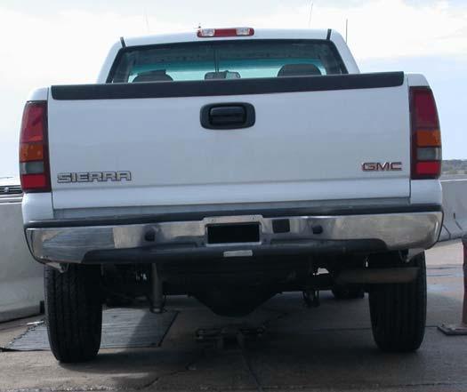
16 Figure 1. Test Vehicle, Test 2214TB-1 7
17 Figure 2. Vehicle Dimensions, Test 2214TB-1 8
18 The Suspension Method (4) was used to determine the vertical component of the center of gravity (c.g.) for the pickup truck. This method is based on the principle that the c.g. of any freely suspended body is in the vertical plane through the point of suspension. The vehicle was suspended successively in three positions, and the respective planes containing the c.g. were established. The intersection of these planes pinpointed the location of the center of gravity. The longitudinal component of the c.g. was determined using the measured axle weights. The location of the final center of gravity is shown in Figures 1 and 2. Square black and white-checkered targets were placed on the vehicle to aid in the analysis of the high-speed film and E/cam and Photron video, as shown in Figure 3. Checkered targets were placed on the center of gravity, on the driver s side door, on the passenger s side door, and on the roof of the vehicle. The remaining targets were located for reference so that they could be viewed from the high-speed cameras for film analysis. The front wheels of the test vehicle were aligned for camber, caster, and toe-in values of zero so that the vehicle would track properly along the guide cable. Two 5B flash bulbs were mounted on both the hood and roof of the vehicle to pinpoint the time of impact with the barrier on the highspeed film, E/cam video, and Photron video. The flash bulbs were fired by a pressure tape switch mounted on the front face of the bumper. A remote-controlled brake system was installed in the test vehicle so the vehicle could be brought safely to a stop after the test. 3.4 Data Acquisition Systems Accelerometers One triaxial piezoresistive accelerometer system with a range of ±200 Gs was used to measure the acceleration in the longitudinal, lateral, and vertical directions at a sample rate of 10,000 9
19 Figure 3. Vehicle Target Locations, Test 2214TB-1 10
20 Hz. The environmental shock and vibration sensor/recorder system, Model EDR-4M6, was developed by Instrumented Sensor Technology (IST) of Okemos, Michigan and includes three differential channels as well as three single-ended channels. The EDR-4 was configured with 6 MB of RAM memory and a 1,500 Hz lowpass filter. Computer software, DynaMax 1 (DM-1) and DADiSP, was used to analyze and plot the accelerometer data. Another triaxial piezoresistive accelerometer system with a range of ±200 Gs was also used to measure the acceleration in the longitudinal, lateral, and vertical directions at a sample rate of 3,200 Hz. The environmental shock and vibration sensor/recorder system, Model EDR-3, was developed by Instrumental Sensor Technology (IST) of Okemos, Michigan. The EDR-3 was configured with 256 kb of RAM memory and a 1,120 Hz lowpass filter. Computer software, DynaMax 1 (DM-1) and DADiSP, was used to analyze and plot the accelerometer data Rate Transducers An Analog Systems 3-axis rate transducer with a range of 1,200 degrees/sec in each of the three directions (pitch, roll, and yaw) was used to measure the rates of motion of the test vehicle. The rate transducer was mounted inside the body of the EDR-4M6 and recorded data at 10,000 Hz to a second data acquisition board inside the EDR-4M6 housing. The raw data measurements were then downloaded, converted to the appropriate Euler angles for analysis, and plotted. Computer software, DynaMax 1 (DM-1) and DADiSP, was used to analyze and plot the rate transducer data High-Speed Photography For test 2214TB-1, two high-speed 16-mm Red Lake Locam cameras, with operating speeds of approximately 500 frames/sec, were used to film the crash test. Two high-speed Photron video 11
21 cameras and four high-speed Red Lake E/cam video cameras, all with operating speeds of 500 frames/sec, and five Canon digital video cameras, with a standard operating speed of frames/sec, were also used to film the crash test. Camera details and a schematic of all thirteen camera locations for test 2214TB-1 is shown in Figure 4. The Locam films, Photron video, and E/cam videos were analyzed using the Vanguard Motion Analyzer, ImageExpress MotionPlus software, and Redlake Motion Scope software, respectively. Actual camera speed and camera divergence factors were considered in the analysis of the high-speed film Pressure Tape Switches For test 2214TB-1, five pressure-activated tape switches, spaced at 2-m (6.56-ft) intervals, were used to determine the speed of the vehicle before impact. Each tape switch fired a strobe light which sent an electronic timing signal to the data acquisition system as the left-front tire of the test vehicle passed over it. Test vehicle speed was determined from electronic timing mark data recorded using Test Point software. Strobe lights and high-speed film analysis are used only as a backup in the event that vehicle speed cannot be determined from the electronic data. 12
22 13 Figure 4. Location of High-Speed Cameras, Test 2214TB-1
23 4 DESIGN DETAILS The m (204.5-ft) long test installation consisted of temporary concrete barriers in a free-standing configuration, as shown in Figures 5 through 9. The sixteen 3,810-mm (12-ft 6-in.) long, F-shaped temporary concrete barriers were placed on the concrete tarmac without any attachment between the barriers and the tarmac. The corresponding English-unit drawings are shown in Appendix A. Photographs of the test installation are shown in Figures 10 through 12. The concrete used for the barriers consisted of Iowa s Barrier Mix, with a minimum 28-day concrete compressive strength of 34.5 MPa (5,000 psi). The minimum concrete cover varied at different positions of rebar in the barrier. A minimum concrete cover of 51 mm (2 in.) was used along the top of the vertical stirrup rebar and the bottom longitudinal rebar. Minimum concrete cover of 44 mmm (1.75 in.) and 25 mm (1 in.) were used along the sides of the vertical stirrup rebar and at the rebar around the anchor bolt block, respectively. All the steel reinforcement in the barier was ASTM A615 Grade 60 rebar, except for the loop bars, which were ASTM A706 Grade 60 rebar. The barrier reinforcement details are shown in Figures 5 through 9. Barrier reinforcement consisted of three No. 5 and two No. 4 longitudinal bars, twelve No. 4 bars for the vertical stirrups, and six No. 6 bars for the anchor bolt block reinforcement loops. Each of the five longitudinal rebar was 3.71 m (12 ft - 2 in.) long. The vertical spacings of the lower, middle, and upper longitudinal bars were 165 mm (6.5 in.), 368 mm (14.5 in.), and 780 mm ( in.) from the ground to their centers, respectively. The 1,829-mm (72-in.) long, vertical stirrups were bent into the shape of the barrier. Their spacings varied longitudinally, as shown in Figure 6. The 889-mm (35-in.) long, anchor bolt block loops were bent into a U-shape and were used to reinforce the anchor bolt area, as shown in Figures 6 through 8. 14
24 The barriers used a pin and loop type connection comprised of two sets of rebar loops on each barrier interconnection. Each loop assembly was configured with three ASTM A706 Grade 60 No. 6 bars that were bent into a loop shape, as shown in Figure 8. The vertical pin used in the connection consisted of a 32-mm (1.25 in.) diameter x 711-mm (28-in.) long round bar composed of ASTM, A36 steel, as shown in Figure 9. The pin was held in place using one 64-mm wide x 102-mm long x 13-mm thick (2.5-in. x 4-in. x 0.5-in.) ASTM A36 steel plate with a 35-mm ( in.) diameter hole centered on it. The plate was welded 64 mm (2.5 in.) below the top of the pin. A gap of 92 mm (3.625 in.) between the ends of two consecutive barriers was formed from the result of pulling the connection taut. 15
25 16 Figure 5. Layout for Free-Standing Temporary Barriers
26 17 Figure 6. Temporary Barrier Design Details
27 Figure 7. Temporary Barrier Profile Details 18
28 Figure 8. Temporary Barrier Bill of Bars 19
29 20 Figure 9. Temporary Barrier Connection Details


30 Figure 10. Temporary Barrier System 21


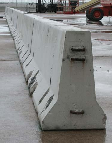
31 22 Figure 11. Temporary Barrier System

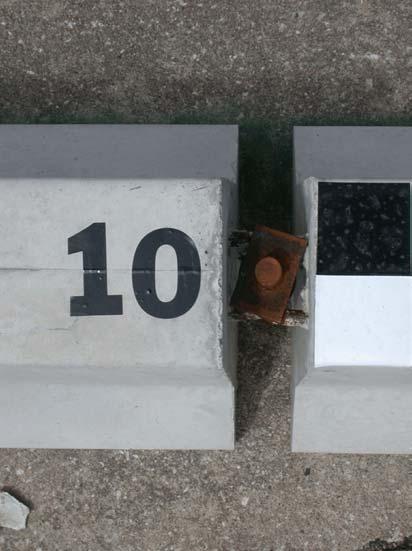

32 23 Figure 12. Barrier Connection Joints
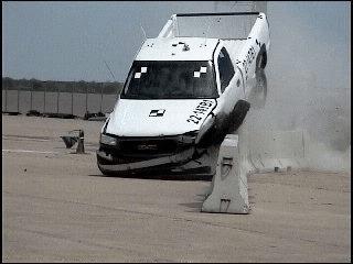
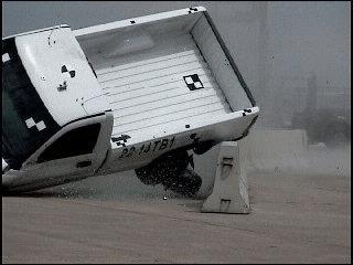
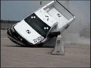
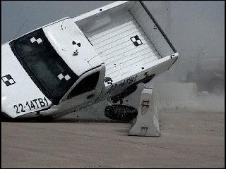
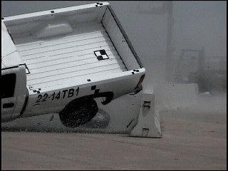
33 5 CRASH TEST 5.1 Test 2214TB-1 The 2,268-kg (5,000-lb) pickup truck impacted the free-standing temporary barrier system at a speed of 99.5 km/h (61.9 mph) and at an angle of 25.7 degrees. A summary of the test results and sequential photographs are shown in Figure 13. The summary of the test results and sequential photographs in English units are shown in Appendix B. Additional sequential photographs are shown in Figures 14 through 17. Documentary photographs of the crash test are shown in Figures 18 and Test Description Initial vehicle impact was to occur 1,219 mm (48 in.) upstream from the center of the gap between barrier nos. 8 and 9, as shown in Figure 20. Actual vehicle impact occurred 1,645 mm (64.75 in.) upstream from the center of the gap between barrier nos. 8 and 9. At sec after initial impact, the left-front corner crushed inward as the left-front corner of the hood protruded over the top of barrier no. 8. At sec, concrete dust appeared as barrier no. 8 encountered damage from impact with the left-front tire. At this same time, the left-front quarter panel crushed. At sec, barrier no. 8 deflected backward as the hood continued to protrude over the top of the barrier. At sec, the left-front corner of the hood was located at the joint between barrier nos. 8 and 9. At this same time, barrier no. 9 began deflecting backward and a gap formed between the top of the left-side door and the rest of the vehicle s cab. At sec, the hood deformed up and away from the rest of the vehicle. At this same time, vertical cracks appeared on the back side of barrier no. 9. At sec, the left-front corner of the hood was located at the middle of barrier no. 9 as barrier nos. 8 and 9 continued to deflect backwards. At sec, the left-front side of vehicle was 24
34 positioned on top of barrier no. 9. At this same time, the cracks on the back side of barrier no. 9 increased in number and severity. At sec, the left-front corner of the hood was located at the joint between barrier nos. 9 and 10 as barrier no. 10 began to deflect backward. At sec after impact, the vehicle became parallel to the system with a resultant velocity of 71.7 km/h (44.5 mph). At this same time, the front half of the left side of the vehicle rode along the top of barrier nos. 9 and 10 with the left-rear tire airborne. At sec, the vehicle redirected away from the system with the front of the vehicle located near the center of barrier no. 10. At this same time, the left side of the vehicle continued to travel on top of barrier nos. 9 and 10. At sec, the left-rear tire contacted the middle of barrier no. 9 as the vehicle experienced clockwise (CW) roll away from the barrier. At this same time, chunks of concrete disengaged from the top of barrier no. 9. At sec, barrier no. 10 continued to sustain significant deflection backward as the vehicle continued to roll CW away from the barrier. At sec, the left-rear tire was on top of barrier no. 9, and the rightrear tire was airborne. At sec, the vehicle rode along the top of barrier no. 10. At this same time, the right-front corner of the vehicle pitched downward as the vehicle continued to roll CW away from the barrier. At sec, the vehicle continued to ride along the top of barrier nos. 10 and 11. At this same time, barrier nos. 7 through 10 continued to deflect backward. At sec, the front of the vehicle continued to pitch downward with the rear of the vehicle rising higher into the air. At sec, the left-front tire rotated outward and was compressed into the top of the barrier. At sec, the vehicle s rear-end reached its maximum height in the air as its front end pitched downward. At sec, the left-front tire disengaged from the axle. At sec, the vehicle levels out with the rear of the vehicle still airborne. At sec, the vehicle rolled counterclockwise (CCW) toward the barrier system and pitched toward the left-front corner of the vehicle. 25
35 At sec, the right-front tire was airborne. At sec, the disengaged left-front tire contacted the left-side window, which shattered. At sec, the disengaged left-front tire was lodged between the left-side door and the barrier. At sec, the left side of the box contacted and rode along the top of the barrier system. At sec, the vehicle exited the system at an approximate angle of 12 degrees and an approximate velocity of 60 km/h (37.3 mph). At sec, the right side tires remained airborne with the vehicle rolling significantly CCW. At sec, the truck was no longer in contact with the barrier. At sec, the vehicle slid along as it remained rolled significantly CCW toward the left side of the vehicle, but began to roll back CW. At this same time, the vehicle yawed CW. At sec, the vehicle continued to yaw CW as the vehicle leveled out and the right-front tire contacted the ground. At sec, the right-rear tire contacted the ground. The vehicle came to rest m (163 ft in.) downstream from impact and 6.24 m (20 ft in.) laterally away from the traffic-side face of the temporary barrier system. The trajectory and final position of the pickup truck are shown in Figures 13 and Barrier Damage Damage to the barrier was moderate, as shown in Figures 22 through 26. Barrier damage consisted of contact and gouge marks, concrete barrier cracking, and spalling of the concrete. The length of vehicle contact along the temporary concrete barrier system was approximately 30 m (98 ft), which spanned from 1,600 mm (63 in.) upstream from the downstream end of barrier no. 8 through 864 mm (34 in.) downstream from the upstream end of barrier no. 16. Tire marks were visible on the front face of barrier nos. 8 through 10. Contact marks were found on the top of barrier nos. 8, 9, and 12 through 16. Yellow contact marks began 483 mm (19 in.) upstream from the downstream end of barrier no. 8 and 152 mm (6 in.) from the top of the 26
36 barrier and continued through the downstream end of barrier no. 8. Concrete spalling occurred at impact on barrier no. 8. The lower-front corner at the downstream end of barrier no. 8 was fractured and separated. The front upstream edge of barrier no. 9 encountered concrete spalling 305 mm (12 in.) from the top of the barrier and was approximately 76 mm (3 in.) long. Concrete spalling found on the backside of the upstream end of barrier no. 9 was 102 mm (4 in.) wide and 483 mm (19 in.) long starting at the top of the barrier. Concrete spalling was found on the bottom-front face 965 mm (38 in.) downstream from the upstream end of barrier no. 9 and was 330 mm (13 in.) wide by 203 mm (8 in.) tall. A 305-mm (12-in.) wide piece of concrete was separated from the top of barrier no. 9 and exposed the top rebar beginning 1,321 mm (52 in.) downstream from the upstream end of the barrier. Concrete spalling with an average width of 102 mm (4 in.) was located 2,540 mm (100 in.) downstream from the upstream end of barrier no. 9 and exposed the longitudinal rebar. Concrete spalling occurred from 1,803 mm (71 in.) to 2,540 mm (100 in.) downstream from the upstream end of barrier no. 9. A 191-mm (7.5-in.) long piece of concrete, with an average width of 279 mm (11 in.), was separated from barrier no. 9 beginning 2,540 mm (100 in.) downstream from the upstream end of the barrier and exposing the stirrup. The concrete on the backside of barrier no. 9 was completely fractured 1,422 mm (56 in.) downstream from the upstream end of the barrier. The backside of barrier no. 10 encountered significant spalling measuring 76 mm (3 in.) wide by 343 mm (13.5 in.) long starting at the top of the barrier. Minor concrete spalling was found 660 mm (26 in.) downstream from the upstream end of the barrier no. 10. An 89-mm (3.5-in.) wide by 203-mm (8-in.) long area of concrete spalling was found on barrier no. 10 beginning 1,829 mm (72 in.) downstream from the barrier s upstream end. Minor concrete spalling measuring 89 mm (3.5 in.) wide by 51 mm (2 in.) tall was found 114 mm (4.5 in.) upstream 27
37 from the downstream end of barrier no. 10. Minor spalling was also found on barrier no. 14. Cracking was found on barrier no. 8 and began 1,372 mm (54 in.) upstream from the downstream end of the barrier and extended upward and slightly downstream along the front face of the barrier. This crack was also visible on the backside of barrier no. 8. Cracking occurred on both the front and back sides of barrier no. 9 beginning 686 mm (27 in.) downstream from the upstream end of the barrier. Two cracks were found 1,270 mm (50 in.) downstream from the upstream end of the barrier and began at the upper-left corner of the upstream lifting slot propagating up and around to the back side of the barrier. Another crack on barrier no. 9 occurred 1,562 mm (61.5 in.) downstream from the upstream end of the barrier at the upper-right corner of the upstream lifting slot. Minor cracking in barrier no. 9 occurred on the top and back side at 2,032 mm (80 in.) downstream from the upstream end of the barrier. Cracking was found on barrier no. 10 beginning at the upper-left corners of both lifting slots and propagating upward to the top of the barrier. Barrier no. 11 encountered a small crack which began at the upper-left corner of the downstream lifting slot and propagated to the midpoint of the top face of the barrier. The connection pin between barrier nos. 8 and 9 was bent 102 mm (4 in.) from the top of the pin. The connection pin between barrier nos. 9 and 10 was bent approximately 127 mm (5 in.) from the bottom of the pin. The connection pins between barrier nos. 10 and 16 remained undamaged, but were lodged in the joints. No noticeable deformations were found on the barrier joint loops. The permanent set of the barrier system is shown in Figure 22. Barrier nos. 6 through 16 encountered longitudinal and lateral movement. The maximum lateral permanent set barrier deflection was 1,441 mm (56.75 in.) at the upstream end of barrier no. 9, as measured in the field. The maximum lateral dynamic barrier deflection was 1,441 mm (56.75 in.) at the upstream end of 28
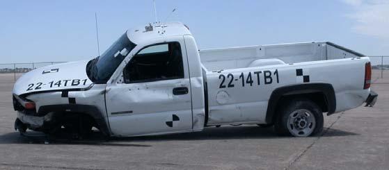
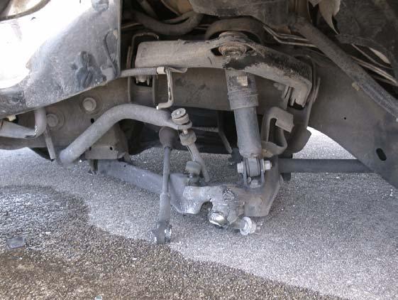
38 barrier no. 9, as determined from high-speed digital video analysis. The working width of the system was found to be 2,013 mm (79.25 in.). 5.4 Vehicle Damage Exterior vehicle damage was moderate, as shown in Figures 27 through 29. Occupant compartment deformations to the left side and center of the floorboard were judged insufficient to cause serious injury to the vehicle occupants. Maximum longitudinal deflections of 146 mm (5.75 in.) were located near the front center of the left-side floor pan. Maximum lateral deflections of 32 mm (1.25 in.) were located near the left-front corner of the left-side floor pan. Maximum vertical deflections of 64 mm (2.5 in.) were located near the left-front corner of the left-side floor pan. Complete occupant compartment deformations and the corresponding locations are provided in Appendix C. Damage was concentrated on the left-front corner of the vehicle. The left-front quarter panel was deformed inward and downward toward the engine compartment. The left side of the front bumper was flattened and bent back toward the engine compartment nearly contacting the lower frame rail. The left-side door encountered a large dent below the window. The top of the left door was ajar. The cab encountered two dents right behind the left-side door. The box encountered numerous dents along the entire right side. The left-front wheel assembly deformed and crushed inward toward the engine compartment. The left-side lower ball joint, top ball joint, and steering linkage were fractured. The left-side sway bar and lower control arm connection was bent. The leftfront tire disengaged from the rest of the wheel assembly. The left-front and left-rear steel rims were deformed and dented. The left-front and left-rear tires side walls were torn, and the tires deflated. The left-side park light disengaged from the vehicle. The left-side door s window glass was 29
39 fractured and missing. The lower-right side of the windshield encountered minor cracking. All other window glass remained undamaged. The right side and rear of the vehicle remained undamaged. 5.5 Occupant Risk Values The longitudinal and lateral occupant impact velocities were determined to be 5.63 m/s (18.46 ft/s) and 5.75 m/s (18.88 ft/s), respectively. The maximum sec average occupant ridedown decelerations in the longitudinal and lateral directions were Gs and 6.52 Gs, respectively. It is noted that the occupant impact velocities (OIVs) and occupant ridedown decelerations (ORDs) were within the suggested limits provided in NCHRP Report No The THIV and PHD values were determined to be 8.50 m/s (27.89 ft/s) and Gs, respectively. The results of the occupant risk, as determined from the accelerometer data, are summarized in Figure 13. Results are shown graphically in Appendix D. The results from the rate transducer are shown graphically in Appendix D. 5.6 Discussion The analysis of the test results for test no. 2214TB-1 showed that the free-standing temporary concrete barrier system impacted with the with the 2270P vehicle of the Update to NCHRP Report No. 350 adequately contained and redirected the vehicle with controlled lateral displacements of the barrier system. There were no detached elements nor fragments which showed potential for penetrating the occupant compartment nor presented undue hazard to other traffic. Deformations of, or intrusion into, the occupant compartment that could have caused serious injury did not occur. However, it should be noted that the left-front wheel assembly disengaged from the vehicle and impacted the left-side door s window and fractured it. The test vehicle did not penetrate nor ride over the temporary concrete barrier system and remained upright during and after the collision. 30
40 Vehicle roll, pitch, and yaw angular displacements were noted, but they were deemed acceptable because they did not adversely influence occupant risk safety criteria nor cause rollover. After collision, the vehicle s trajectory revealed minimum intrusion into adjacent traffic lanes. In addition, the vehicle exited the barrier within the exit box. Therefore, test no. 2214TB-1 conducted on the free-standing temporary concrete barrier system was determined to be acceptable according to the TL-3 safety performance criteria found in the Update to NCHRP Report No It should be noted that the center of gravity of 686 mm (27 in.) of the pickup tested was determined to be at the low end of the c.g. height range of the large passenger vehicle class (i.e., light trucks) currently on the roadways. Consequently, this vehicle was judged to not be an accurate representation of the light trucks on the roadways, which accounts for approximately half of all vehicles sold in the United States. Since it was desired that the test vehicle represented the taller vehicles in this class, a minimum c.g. height of 710 mm (28 in.) was set. 31
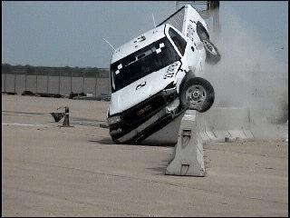
41 0.000 sec sec sec sec sec! Test Agency... MwRSF! Test Number TB-1! Date... 5/4/04! NCHRP 350 Update Test Designation ! Appurtenance... Free-Standing Temporary Barrier! Total Length m! Key Elements - Barrier Description... F-Shape Barrier Length... 3,810 mm Base Width mm Height mm! Type of Soil... NA! Test Vehicle Type/Designation P Make and Model GMC 2500 ¾-ton Pickup Curb... 2,279 kg Test Inertial... 2,268 kg Gross Static... 2,268 kg! Impact Conditions Speed km/h Angle degrees Impact Location m upstream barriers 8 & 9 joint! Exit Conditions Speed km/h (est.) Angle degrees (est.) Exit Box Criterion... Pass Figure 13. Summary of Test Results and Sequential Photographs, Test 2214TB-1! Post-Impact Trajectory Vehicle Stability... Satisfactory Stopping Distance m downstream 6.24 m traffic-side face! Occupant Impact Velocity (350 Update) Longitudinal m/s < 12 m/s Lateral m/s < 12 m/s! Occupant Ridedown Deceleration (350 Update) Longitudinal Gs < 20 Gs Lateral Gs < 20 Gs! THIV (not required) m/s! PHD (not required) Gs! Test Article Damage... Moderate! Test Article Deflections Permanent Set... 1,441 mm Dynamic... 1,441 mm Working Width... 2,013 mm! Vehicle Damage... Moderate VDS LFQ-3 CDC LYES4 Maximum Deformation mm at front floorpan 32


42 0.000 sec sec sec sec sec sec sec sec sec sec Figure 14. Additional Sequential Photographs, Test 2214TB-1 33


43 0.000 sec sec sec sec sec sec sec sec sec sec Figure 15. Additional Sequential Photographs, Test 2214TB-1 34


44 0.000 sec sec sec sec sec sec sec sec sec sec Figure 16. Additional Sequential Photographs, Test 2214TB-1 35


45 0.000 sec sec sec sec sec sec sec sec sec sec sec Figure 17. Additional Sequential Photographs, Test 2214TB sec

46 Figure 18. Documentary Photographs, Test 2214TB-1 37
47 Figure 19. Documentary Photographs, Test 2214TB-1 38


48 Figure 20. Impact Location, Test 2214TB-1 39


49 Figure 21. Vehicle Final Position and Trajectory Marks, Test 2214TB-1 40


50 41 Figure 22. Temporary Barrier Damage, Test 2214TB-1


51 Figure 23. Temporary Barrier Damage, Test 2214TB-1 42


52 Figure 24. Temporary Barrier Damage, Test 2214TB-1 43


53 Figure 25. Temporary Barrier Damage, Test 2214TB-1 44


54 Figure 26. Temporary Barrier Damage, Test 2214TB-1 45


55 46 Figure 27. Vehicle Damage, Test 2214TB-1


56 47 Figure 28. Vehicle Damage, Test 2214TB-1


57 Figure 29. Vehicle Damage, Test 2214TB-1 48
58 6 SUMMARY AND CONCLUSIONS A free-standing temporary barrier system was constructed and full-scale vehicle crash tested. One full-scale vehicle crash test, using a pickup truck vehicle, was performed on the longitudinal barrier system and was determined to be acceptable according to the TL-3 safety performance criteria presented in the Update to NCHRP Report No A summary of the safety performance evaluation is provided in Table 3. While the vehicle mass and impact conditions are included in the proposed Update to NCHRP Report No. 350, the ¾-ton, 2-door pickup truck utilized in this test was ultimately not recommended in the Update to NCHRP Report No
59 Table 3. Summary of Safety Performance Evaluation Results Evaluation Factors Structural Adequacy Occupant Risk Vehicle Trajectory Evaluation Criteria A. Test article should contain and redirect the vehicle or bring the vehicle to a controlled stop; the vehicle should not penetrate, underride, or override the installation although controlled lateral deflection of the test article is acceptable. D. Detached elements, fragments or other debris from the test article should not penetrate or show potential for penetrating the occupant compartment, or present an undue hazard to other traffic, pedestrians, or personnel in a work zone. Deformations of, or intrusions into, the occupant compartment should not exceed limits set forth in Section 5.3 and Appendix E of the Update to NCHRP Report No F. The vehicle should remain upright during and after collision. H. Longitudinal and lateral occupant impact velocities should fall below the preferred value of 9.0 m/s (29.5 ft/s), or at least below the maximum allowable value of 12.0 m/s (39.4 ft/s). I. Longitudinal and lateral occupant ridedown accelerations should fall below the preferred value of 15 Gs, or at least below the maximum allowable value of 20.0 Gs. M. After impact, the vehicle shall exit the barrier within the exit box. Test 2214TB-1 S S S S S S S - Satisfactory U - Unsatisfactory NA - Not Available 50
60 7 REFERENCES 1. Ross, H.E., Sicking, D.L., Zimmer, R.A., and Michie, J.D., Recommended Procedures for the Safety Performance Evaluation of Highway Features, National Cooperative Research Program (NCHRP) Report No. 350, Transportation Research Board, Washington, D.C., Sicking, D.L., Mak, K.K., and Rohde, J.R., NCHRP Report No. 350 Update - Chapters 1 through 7, Draft Report, Presented to the Transportation Research Board, Prepared by the Midwest Roadside Safety Facility, University of Nebraska-Lincoln, July 2005 [Privileged Document]. 3. Hinch, J., Yang, T.L., and Owings, R., Guidance Systems for Vehicle Testing, ENSCO, Inc., Springfield, VA, Center of Gravity Test Code - SAE J874 March 1981, SAE Handbook Vol. 4, Society of Automotive Engineers, Inc., Warrendale, Pennsylvania, Vehicle Damage Scale for Traffic Investigators, Second Edition, Technical Bulletin No. 1, Traffic Accident Data (TAD) Project, National Safety Council, Chicago, Illinois, Collision Deformation Classification - Recommended Practice J224 March 1980, Handbook Volume 4, Society of Automotive Engineers (SAE), Warrendale, Pennsylvania,
61 8 APPENDICES 52
62 APPENDIX A English-Unit System Drawings Figure A-1. Layout for Free-Standing Temporary Barriers (English) Figure A-2. Temporary Barrier Design Details (English) Figure A-3.Temporary Barrier Profile Details (English) Figure A-4. Temporary Barrier Bill of Bars (English) Figure A-5. Temporary Barrier Connection Details (English) 53
63 54 Figure A-1. Layout for Free-Standing Temporary Barriers (English)
64 55 Figure A-2. Temporary Barrier Design Details (English)
65 Figure A-3. Temporary Barrier Profile Details (English) 56
66 Figure A-4. Temporary Barrier Bill of Bars (English) 57
67 58 Figure A-5. Temporary Barrier Connection Details (English)
68 APPENDIX B Test Summary Sheet in English Units Figure B-1. Summary of Test Results and Sequential Photographs (English), Test 2214TB-1 59
69 0.000 sec sec sec sec sec! Test Agency... MwRSF! Test Number TB-1! Date... 5/4/04! NCHRP 350 Update Test Designation ! Appurtenance... Free-Standing Temporary Barrier! Total Length ft - 6 in.! Key Elements - Barrier Description... F-Shape Barrier Length ft - 6 in. Base Width in. Height in.! Type of Soil... NA! Test Vehicle Type/Designation P Make and Model GMC 2500 ¾-ton Pickup Curb... 5,024 lbs Test Inertial... 5,000 lbs Gross Static... 5,000 lbs! Impact Conditions Speed mph Angle degrees Impact Location... 5 ft in. upstream barriers 8 & 9 joint! Exit Conditions Speed mph (est.) Angle degrees (est.) Exit Box Criterion... Pass Figure B-1. Summary of Test Results and Sequential Photographs (English), Test 2214TB-1! Post-Impact Trajectory Vehicle Stability... Satisfactory Stopping Distance ft in. downstream 20 ft in. traffic-side face! Occupant Impact Velocity (350 Update) Longitudinal ft/s < 39.4 ft/s Lateral ft/s < 39.4 ft/s! Occupant Ridedown Deceleration (350 Update) Longitudinal Gs < 20 Gs Lateral Gs < 20 Gs! THIV (not required) ft/s! PHD (not required) Gs! Test Article Damage... Moderate! Test Article Deflections Permanent Set in. Dynamic in. Working Width in.! Vehicle Damage... Moderate VDS LFQ-3 CDC LYES4 Maximum Deformation in. at front floorpan 60
70 APPENDIX C Occupant Compartment Deformation Data, Test 2214TB-1 Figure C-1. Occupant Compartment Deformation Data, Test 2214TB-1 Figure C-2. Occupant Compartment Deformation Index (OCDI), Test 2214TB-1 Figure C-3. NASS Crush Data, Test 2214TB-1 61
71 62 Figure C-1. Occupant Compartment Deformation Data, Test 2214TB-1
72 Figure C-2. Occupant Compartment Deformation Index (OCDI), Test 2214TB-1 63
73 Figure C-3. NASS Crush Data, Test 2214TB-1 64
74 APPENDIX D Accelerometer and Rate Transducer Data Analysis, Test 2214TB-1 Figure D-1. Graph of Longitudinal Deceleration, Test 2214TB-1 Figure D-2. Graph of Longitudinal Occupant Impact Velocity, Test 2214TB-1 Figure D-3. Graph of Longitudinal Occupant Displacement, Test 2214TB-1 Figure D-4. Graph of Lateral Deceleration, Test 2214TB-1 Figure D-5. Graph of Lateral Occupant Impact Velocity, Test 2214TB-1 Figure D-6. Graph of Lateral Occupant Displacement, Test 2214TB-1 Figure D-7. Graph of Yaw Angular Displacements, Test 2214TB-1 65
PERFORMANCE EVALUATION OF THE FREE-STANDING TEMPORARY BARRIER UPDATE TO NCHRP 350 TEST NO WITH 28" C.G. HEIGHT (2214TB-2)
") PERFORMANCE EVALUATION OF THE FREE-STANDING TEMPORARY BARRIER UPDATE TO NCHRP 350 TEST NO. 3-11 WITH 28" C.G. HEIGHT (2214TB-2) Submitted by Karla A. Polivka, M.S.M.E., E.I.T. Research Associate Engineer
PERFORMANCE EVALUATION OF THE FREE-STANDING TEMPORARY BARRIER UPDATE TO NCHRP 350 TEST NO. 3-11 WITH 28" C.G. HEIGHT (2214TB-2) Submitted by Karla A. Polivka, M.S.M.E., E.I.T. Research Associate Engineer
PERFORMANCE EVALUATION OF THE PERMANENT NEW JERSEY SAFETY SHAPE BARRIER UPDATE TO NCHRP 350 TEST NO (2214NJ-2)
") PERFORMANCE EVALUATION OF THE PERMANENT NEW JERSEY SAFETY SHAPE BARRIER UPDATE TO NCHRP 350 TEST NO. 4-12 (2214NJ-2) Submitted by Karla A. Polivka, M.S.M.E., E.I.T. Research Associate Engineer Dean L.
PERFORMANCE EVALUATION OF THE PERMANENT NEW JERSEY SAFETY SHAPE BARRIER UPDATE TO NCHRP 350 TEST NO. 4-12 (2214NJ-2) Submitted by Karla A. Polivka, M.S.M.E., E.I.T. Research Associate Engineer Dean L.
PERFORMANCE EVALUATION OF THE MODIFIED G4(1S) GUARDRAIL UPDATE TO NCHRP 350 TEST NO WITH 28" C.G. HEIGHT (2214WB-2)
 GUARDRAIL UPDATE TO NCHRP 350 TEST NO WITH 28 C.G. HEIGHT (2214WB-2)") PERFORMANCE EVALUATION OF THE MODIFIED G4(1S) GUARDRAIL UPDATE TO NCHRP 350 TEST NO. 3-11 WITH 28" C.G. HEIGHT (2214WB-2) Submitted by Karla A. Polivka, M.S.M.E., E.I.T. Research Associate Engineer Dean
PERFORMANCE EVALUATION OF THE MODIFIED G4(1S) GUARDRAIL UPDATE TO NCHRP 350 TEST NO. 3-11 WITH 28" C.G. HEIGHT (2214WB-2) Submitted by Karla A. Polivka, M.S.M.E., E.I.T. Research Associate Engineer Dean
DEFLECTION LIMITS FOR TEMPORARY CONCRETE BARRIERS
 Midwest State s Regional Pooled Fund Research Program Fiscal Year 1998-1999 (Year 9) NDOR Research Project Number SPR-3(017) DEFLECTION LIMITS FOR TEMPORARY CONCRETE BARRIERS Submitted by Dean L. Sicking,
Midwest Guardrail System Without Blockouts
 Duplication for publication or sale is strictly prohibited without prior written permission of the Transportation Research Board Paper No. 13-0418 Midwest Guardrail System Without Blockouts by John D.
Evaluation of the Midwest Guardrail System Stiffness Transition with Curb
 Duplication for publication or sale is strictly prohibited without prior written permission of the Transportation Research Board Paper No. -0 Evaluation of the Midwest Guardrail System Stiffness Transition
February 8, In Reply Refer To: HSSD/CC-104
 February 8, 2008 200 New Jersey Avenue, SE. Washington, DC 20590 In Reply Refer To: HSSD/CC-04 Barry D. Stephens, P.E. Sr. Vice President Engineering Energy Absorption Systems, Inc. 367 Cincinnati Avenue
NCHRP Report 350 Test 4-12 of the Modified Thrie Beam Guardrail
 NCHRP Report 350 Test 4-12 of the Modified Thrie Beam Guardrail PUBLICATION NO. FHWA-RD-99-065 DECEMBER 1999 Research, Development, and Technology Turner-Fairbank Highway Research Center 6300 Georgetown
A MASH Compliant W-Beam Median Guardrail System
 0 0 0 0 0 A MASH Compliant W-Beam Median Guardrail System By A. Y. Abu-Odeh, R. P. Bligh, W. Odell, A. Meza, and W. L. Menges Submitted: July 0, 0 Word Count:, + ( figures + tables=,000) =, words Authors:
Form DOT F (8-72) Texas Transportation Institute The Texas A&M University System College Station, Texas
 Texas Transportation Institute The Texas A&M University System College Station, Texas") 1. Report No. FHWA/TX-02/4162-1 Technical Report Documentation Page 2. Government Accession No. 3. Recipient's Catalog No. 4. Title and Subtitle EVALUATION OF TEXAS GRID-SLOT PORTABLE CONCRETE BARRIER
1. Report No. FHWA/TX-02/4162-1 Technical Report Documentation Page 2. Government Accession No. 3. Recipient's Catalog No. 4. Title and Subtitle EVALUATION OF TEXAS GRID-SLOT PORTABLE CONCRETE BARRIER
July 10, Refer to: HSA-10/CC-78A
 July 10, 2003 Refer to: HSA-10/CC-78A Barry D. Stephens, P.E. Senior Vice President of Engineering ENERGY ABSORPTION Systems, Inc. 3617 Cincinnati Avenue Rocklin, California 95765 Dear Mr. Stephens: Your
Evaluation of the Midwest Guardrail System stiffness transition with curb
 University of Nebraska - Lincoln DigitalCommons@University of Nebraska - Lincoln Civil Engineering Faculty Publications Civil Engineering 2016 Evaluation of the Midwest Guardrail System stiffness transition
VERIFICATION & VALIDATION REPORT of MGS Barrier Impact with 1100C Vehicle Using Toyota Yaris Coarse FE Model
 VERIFICATION & VALIDATION REPORT of MGS Barrier Impact with 1100C Vehicle Using Toyota Yaris Coarse FE Model CCSA VALIDATION/VERIFICATION REPORT Page 1 of 4 Project: CCSA Longitudinal Barriers on Curved,
MASH Test 3-11 on the T131RC Bridge Rail
 TTI: 9-1002-12 MASH Test 3-11 on the T131RC Bridge Rail ISO 17025 Laboratory Testing Certificate # 2821.01 Crash testing performed at: TTI Proving Ground 3100 SH 47, Building 7091 Bryan, TX 77807 Test
Texas Transportation Institute The Texas A&M University System College Station, Texas
 1. Report No. FHWA/TX-05/9-8132-P7 4. Title and Subtitle TL-4 CRASH TESTING OF THE F411 BRIDGE RAIL 2. Government Accession No. 3. Recipient's Catalog No. 5. Report Date October 2004 Technical Report Documentation
NCHRP Report 350 Crash Testing and Evaluation of the S-Square Mailbox System
 TTI: 0-5210 NCHRP Report 350 Crash Testing and Evaluation of the S-Square Mailbox System ISO 17025 Laboratory Testing Certificate # 2821.01 Crash testing performed at: TTI Proving Ground 3100 SH 47, Building
PR V2. Submitted by. Professor MIDWEST Vine Street (402) Submitted to
 Submitted to") FINAL REPORT PR4893118-V2 ZONE OF INTRUSION STUDY Submitted by John D. Reid, Ph.D. Professor Dean L.. Sicking, Ph.D., P.E. Professorr and MwRSF Director MIDWEST ROADSIDE SAFETY FACILITY University of Nebraska-Lincoln
FINAL REPORT PR4893118-V2 ZONE OF INTRUSION STUDY Submitted by John D. Reid, Ph.D. Professor Dean L.. Sicking, Ph.D., P.E. Professorr and MwRSF Director MIDWEST ROADSIDE SAFETY FACILITY University of Nebraska-Lincoln
Manual for Assessing Safety Hardware
 American Association of State Highway and Transportation Officials Manual for Assessing Safety Hardware 2009 vii PREFACE Effective traffic barrier systems, end treatments, crash cushions, breakaway devices,
STI Project: Barrier Systems, Inc. RTS-QMB Longitudinal Barrier. Page 38 of 40 QBOR1. Appendix F (Continued) Figure F-3
 Figure F-3") Barrier Systems, Inc. RTS-QMB Longitudinal Barrier STI Project: QBOR1 Page 38 of 40 Appendix F (Continued) Figure F-3 t=.500sec 115 meters overall 37.1 Impact Severity (kj).. 141.6 Angle (deg).. 25 Speed
Barrier Systems, Inc. RTS-QMB Longitudinal Barrier STI Project: QBOR1 Page 38 of 40 Appendix F (Continued) Figure F-3 t=.500sec 115 meters overall 37.1 Impact Severity (kj).. 141.6 Angle (deg).. 25 Speed
CRASH TEST AND EVALUATION OF 3-FT MOUNTING HEIGHT SIGN SUPPORT SYSTEM
 TTI: 9-1002-15 CRASH TEST AND EVALUATION OF 3-FT MOUNTING HEIGHT SIGN SUPPORT SYSTEM ISO 17025 Laboratory Testing Certificate # 2821.01 Crash testing performed at: TTI Proving Ground 3100 SH 47, Building
VULCAN BARRIER TL-3 GENERAL SPECIFICATIONS
 VULCAN BARRIER TL-3 GENERAL SPECIFICATIONS I. GENERAL A. The VULCAN BARRIER TL-3 (VULCAN TL-3) shall be a highly portable and crashworthy longitudinal barrier especially suited for use as a temporary barrier
VULCAN BARRIER TL-3 GENERAL SPECIFICATIONS
 VULCAN BARRIER TL-3 GENERAL SPECIFICATIONS I. GENERAL A. The VULCAN BARRIER TL-3 (VULCAN TL-3) shall be a highly portable and crashworthy longitudinal barrier especially suited for use as a temporary barrier
MASH08 TEST 3-11 OF THE ROCKINGHAM PRECAST CONCRETE BARRIER
 Proving Ground Report No. 400001-RPC4 Report Date: July 2009 MASH08 TEST 3-11 OF THE ROCKINGHAM PRECAST CONCRETE BARRIER by C. Eugene Buth, P.E. Research Engineer William F. Williams, P.E. Assistant Research
MASH TEST 3-11 OF THE TxDOT T222 BRIDGE RAIL
 TTI: 9-1002-12 MASH TEST 3-11 OF THE TxDOT T222 BRIDGE RAIL ISO 17025 Laboratory Testing Certificate # 2821.01 Crash testing performed at: TTI Proving Ground 3100 SH 47, Building 7091 Bryan, TX 77807 Test
Texas Transportation Institute The Texas A&M University System College Station, Texas
 1. Report No. FHWA/TX-07/0-5527-1 4. Title and Subtitle DEVELOPMENT OF A LOW-PROFILE TO F-SHAPE TRANSITION BARRIER SEGMENT 2. Government Accession No. 3. Recipient's Catalog No. Technical Report Documentation
Texas Transportation Institute The Texas A&M University System College Station, Texas
 1. Report No. FHWA/TX-04/9-8132-1 4. Title and Subtitle TESTING AND EVALUATION OF THE FLORIDA JERSEY SAFETY SHAPED BRIDGE RAIL 2. Government Accession No. 3. Recipient's Catalog No. 5. Report Date February
Evaluation and Design of ODOT s Type 5 Guardrail with Tubular Backup
 Evaluation and Design of ODOT s Type 5 Guardrail with Tubular Backup Draft Final Report Chuck A. Plaxico, Ph.D. James C. Kennedy, Jr., Ph.D. Charles R. Miele, P.E. for the Ohio Department of Transportation
Product Specification. ABSORB 350 TM TL-2 Non-Redirective, Gating, Crash Cushion Applied to Quickchange Moveable Barrier
 TB 000612 Rev. 0 Page 1 of 9 Product Specification ABSORB 350 TM TL-2 Non-Redirective, Gating, Crash Cushion Applied to Quickchange Moveable Barrier I. General The ABSORB 350 TM TL-2 System is a Non-Redirective,
MINIMUM EFFECTIVE LENGTH FOR THE MIDWEST GUARDRAIL SYSTEM
 Duplication for publication or sale is strictly prohibited without prior written permission of the Transportation Research Board Paper No. 15-0484 MINIMUM EFFECTIVE LENGTH FOR THE MIDWEST GUARDRAIL SYSTEM
SAFETY PERFORMANCE OF WORK-ZONE DEVICES UNDER MASH TESTING
 SAFETY PERFORMANCE OF WORK-ZONE DEVICES UNDER MASH TESTING Schmidt, Faller, Lechtenberg, Sicking, Holloway Midwest Roadside Safety Facility Nebraska Transportation Center University of Nebraska-Lincoln
Advances in Simulating Corrugated Beam Barriers under Vehicular Impact
 13 th International LS-DYNA Users Conference Session: Automotive Advances in Simulating Corrugated Beam Barriers under Vehicular Impact Akram Abu-Odeh Texas A&M Transportation Institute Abstract W-beam
MASH TEST 3-10 ON 31-INCH W-BEAM GUARDRAIL WITH STANDARD OFFSET BLOCKS
 TTI: 9-1002 MASH TEST 3-10 ON 31-INCH W-BEAM GUARDRAIL WITH STANDARD OFFSET BLOCKS ISO 17025 Laboratory Testing Certificate # 2821.01 Crash testing performed at: TTI Proving Ground 3100 SH 47, Building
SUMMARY CHANGES FOR NCHRP REPORT 350 GUIDELINES [NCHRP (02)] Keith A. Cota, Chairman Technical Committee on Roadside Safety June 14, 2007
![SUMMARY CHANGES FOR NCHRP REPORT 350 GUIDELINES [NCHRP (02)] Keith A. Cota, Chairman Technical Committee on Roadside Safety June 14, 2007](/thumbs/87/97351925.jpg "SUMMARY CHANGES FOR NCHRP REPORT 350 GUIDELINES [NCHRP (02)] Keith A. Cota, Chairman Technical Committee on Roadside Safety June 14, 2007") SUMMARY CHANGES FOR NCHRP REPORT 350 GUIDELINES [NCHRP 22-14 (02)] Keith A. Cota, Chairman Technical Committee on Roadside Safety June 14, 2007 BACKGROUND Circular 482 (1962) First full scale crash test
SUMMARY CHANGES FOR NCHRP REPORT 350 GUIDELINES [NCHRP 22-14 (02)] Keith A. Cota, Chairman Technical Committee on Roadside Safety June 14, 2007 BACKGROUND Circular 482 (1962) First full scale crash test
GUARDRAIL TESTING MODIFIED ECCENTRIC LOADER TERMINAL (MELT) AT NCHRP 350 TL-2. Dean C. Alberson, Wanda L. Menges, and Rebecca R.
 AT NCHRP 350 TL-2. Dean C. Alberson, Wanda L. Menges, and Rebecca R.") GUARDRAIL TESTING MODIFIED ECCENTRIC LOADER TERMINAL (MELT) AT NCHRP 350 TL-2 Dean C. Alberson, Wanda L. Menges, and Rebecca R. Haug Prepared for The New England Transportation Consortium July 2002 NETCR
GUARDRAIL TESTING MODIFIED ECCENTRIC LOADER TERMINAL (MELT) AT NCHRP 350 TL-2 Dean C. Alberson, Wanda L. Menges, and Rebecca R. Haug Prepared for The New England Transportation Consortium July 2002 NETCR
Texas Transportation Institute The Texas A&M University System College Station, Texas
 2. Government Accession No. 3. Recipient's Catalog No. 1. Report No. FHWA/TX-03/0-4138-3 4. Title and Subtitle PERFORMANCE OF THE TXDOT T202 (MOD) BRIDGE RAIL REINFORCED WITH FIBER REINFORCED POLYMER BARS
June 5, In Reply Refer To: HSSD/B-178. Mr. Kevin K. Groeneweg Mobile Barriers LLC Genesee Trail Road Golden, CO Dear Mr.
 June 5, 2008 1200 New Jersey Avenue, SE. Washington, DC 20590 In Reply Refer To: HSSD/B-178 Mr. Kevin K. Groeneweg Mobile Barriers LLC 24918 Genesee Trail Road Golden, CO 80401 Dear Mr. Groeneweg: This
MASH TEST 3-11 OF THE TxDOT SINGLE SLOPE BRIDGE RAIL (TYPE SSTR) ON PAN-FORMED BRIDGE DECK
 ON PAN-FORMED BRIDGE DECK") TTI: 9-1002 MASH TEST 3-11 OF THE TxDOT SINGLE SLOPE BRIDGE RAIL (TYPE SSTR) ON PAN-FORMED BRIDGE DECK ISO 17025 Laboratory Testing Certificate # 2821.01 Crash testing performed at: TTI Proving Ground
TTI: 9-1002 MASH TEST 3-11 OF THE TxDOT SINGLE SLOPE BRIDGE RAIL (TYPE SSTR) ON PAN-FORMED BRIDGE DECK ISO 17025 Laboratory Testing Certificate # 2821.01 Crash testing performed at: TTI Proving Ground
DEVELOPMENT OF A MASH TL-3 TRANSITION BETWEEN GUARDRAIL AND PORTABLE CONCRETE BARRIERS
 Duplication for publication or sale is strictly prohibited without prior written permission of the Transportation Research Board Paper No. 17-01712 DEVELOPMENT OF A MASH TL-3 TRANSITION BETWEEN GUARDRAIL
MASH TEST 3-37 OF THE TxDOT 31-INCH W-BEAM DOWNSTREAM ANCHOR TERMINAL
 TTI: 9-1002 MASH TEST 3-37 OF THE TxDOT 31-INCH W-BEAM DOWNSTREAM ANCHOR TERMINAL ISO 17025 Laboratory Testing Certificate # 2821.01 Crash testing performed at: TTI Proving Ground 3100 SH 47, Building
Virginia Department of Transportation
 TEST REPORT FOR: Virginia Department of Transportation SKT SP 350 50 (15.24 m) System PREPARED FOR: Virginia Department of Transportation 1401 E. Broad St. Richmond, VA 23219 TEST REPORT NUMBER: REPORT
DEVELOPMENT OF A TRANSITION BETWEEN FREE-STANDING AND REDUCED-DEFLECTION PORTABLE CONCRETE BARRIERS PHASE I
 Research Project Number TPF-5(193) Supplement #78 DEVELOPMENT OF A TRANSITION BETWEEN FREE-STANDING AND REDUCED-DEFLECTION PORTABLE CONCRETE BARRIERS PHASE I Submitted by Mojdeh Asadollahi Pajouh, Ph.D.
TEXAS TRANSPORTATION INSTITUTE THE TEXAS A & M UNIVERSITY SYSTEM COLLEGE STATION, TEXAS 77843
 NCHRP REPORT 350 TEST 3-11 OF THE NEW YORK DOT PORTABLE CONCRETE BARRIER WITH I-BEAM CONNECTION (RETEST) by Roger P. Bligh, P.E. Assistant Research Engineer Wanda L. Menges Associate Research Specialist
CRITICAL FLARE RATES FOR W-BEAM GUARDRAIL DETERMINING MAXIMUM CAPACITY USING COMPUTER SIMULATION NCHRP 17-20(3)
") CRITICAL FLARE RATES FOR W-BEAM GUARDRAIL DETERMINING MAXIMUM CAPACITY USING COMPUTER SIMULATION NCHRP 17-2(3) Submitted by Beau D. Kuipers, B.S.M.E., E.I.T. Graduate Research Assistant Ronald K. Faller,
CRITICAL FLARE RATES FOR W-BEAM GUARDRAIL DETERMINING MAXIMUM CAPACITY USING COMPUTER SIMULATION NCHRP 17-2(3) Submitted by Beau D. Kuipers, B.S.M.E., E.I.T. Graduate Research Assistant Ronald K. Faller,
CRASH TESTING AND EVALUATION OF WORK ZONE TRAFFIC CONTROL DEVICES
 Paper No. 980627 CRASH TESTING AND EVALUATION OF WORK ZONE TRAFFIC CONTROL DEVICES by King K. Mak Phone: 210-698-2068 Fax: 210-698-2068 e-mail: king@tti3a.tamu.edu Texas Transportation Institute The Texas
Sponsored by Roadside Safety Research Program Pooled Fund Study No. TPF-5(114)
") Proving Ground Test Report No. 405160-23-2 Test Report Date: February 2012 MASH TEST 3-11 OF THE W-BEAM GUARDRAIL ON LOW-FILL BOX CULVERT by William F. Williams, P.E. Associate Research Engineer and Wanda
Proving Ground Test Report No. 405160-23-2 Test Report Date: February 2012 MASH TEST 3-11 OF THE W-BEAM GUARDRAIL ON LOW-FILL BOX CULVERT by William F. Williams, P.E. Associate Research Engineer and Wanda
Technical Report Documentation Page Form DOT F (8-72) Reproduction of completed page authorized
 Reproduction of completed page authorized") 1. Report No. FHWA/TX-05/0-4162-3 4. Title and Subtitle 2. Government Accession No. 3. Recipient's Catalog No. DEVELOPMENT OF LOW-DEFLECTION PRECAST CONCRETE ARRIER 5. Report Date January 2005 Technical
1. Report No. FHWA/TX-05/0-4162-3 4. Title and Subtitle 2. Government Accession No. 3. Recipient's Catalog No. DEVELOPMENT OF LOW-DEFLECTION PRECAST CONCRETE ARRIER 5. Report Date January 2005 Technical
Universal TAU-IIR Redirective, Non-Gating, Crash Cushion
 TB 110927 Rev. 0 Page 1 of 5 Product Specification Universal TAU-IIR Redirective, Non-Gating, Crash Cushion I. General The Universal TAU-IIR system is a Redirective, Non-Gating Crash Cushion in accordance
BarrierGate. General Specifications. Manual Operations General Specifications
 BarrierGate General Specifications Manual Operations General Specifications BarrierGate GENERAL SPECIFICATIONS I. GENERAL A. The BarrierGate system (the gate) shall be designed and manufactured by Energy
Analysis of Existing Work-Zone Sign Supports Using Manual for Assessing Safety Hardware Safety Performance Criteria
 University of Nebraska - Lincoln DigitalCommons@University of Nebraska - Lincoln Civil Engineering Faculty Publications Civil Engineering 2011 Analysis of Existing Work-Zone Sign Supports Using Manual
DEVELOPMENT OF A TEMPORARY BARRIER SYSTEM FOR OFF-ROAD APPLICATIONS
 DEVELOPMENT OF A TEMPORARY BARRIER SYSTEM FOR OFF-ROAD APPLICATIONS Kenneth H. Addink Graduate Research Assistant Brian G. Pfeifer, Ph.D., P.E. Research Associate Engineer John R. Rohde, Ph.D., P.E. Associate
ROBUST PROJECT Norwegian Public Roads Administration / Force Technology Norway AS
 ROBUST PROJECT Norwegian Public Roads Administration / Force Technology Norway AS Evaluation of small car - RM_R1 - prepared by Politecnico di Milano Volume 1 of 1 January 2006 Doc. No.: ROBUST-5-002/TR-2004-0039
CRASH TESTING OF RSA/K&C ANTI-RAM FOUNDATION BOLLARD PAD IN ACCORDANCE WITH U.S. DEPARTMENT OF STATE DIPLOMATIC SECURITY SD-STD-02.
 CRASH TESTING OF RSA/K&C ANTI-RAM FOUNDATION BOLLARD PAD IN ACCORDANCE WITH U.S. DEPARTMENT OF STATE DIPLOMATIC SECURITY SD-STD-02.01 REVISION A Prepared for RSA Protective Technologies, LLC FINAL REPORT
CRASH TEST REPORT FOR PERIMETER BARRIERS AND GATES TESTED TO SD-STD-02.01, REVISION A, MARCH Anti-Ram Bollards
 CRASH TEST REPORT FOR PERIMETER BARRIERS AND GATES TESTED TO SD-STD-02.01, REVISION A, MARCH 2003 Anti-Ram Bollards Prepared for: RSA Protective Technologies, LLC 1573 Mimosa Court Upland, CA 91784 Test
Development of Combination Pedestrian-Traffic Bridge Railings
 TRANSPORTATION RESEARCH RECORD 1468 41 Development of Combination Pedestrian-Traffic Bridge Railings D. LANCE BULLARD, JR., WANDA L. MENGES, AND C. EUGENE BUTH Two bridge railing designs have been developed
TEXAS TRANSPORTATION INSTITUTE THE TEXAS A & M UNIVERSITY SYSTEM COLLEGE STATION, TEXAS 77843
 NCHRP REPORT 350 TEST 3-11 OF THE STEEL-BACKED TIMBER GUARDRAIL by D. Lance Bullard, Jr., P.E. Associate Research Engineer Wanda L. Menges Associate Research Specialist and Sandra K. Schoeneman Research
W-Beam Guiderail Transition from Light to Heavy Posts
 TRANSPORTATION RESEARCH RECORD 1198 55 W-Beam Guiderail Transition from Light to Heavy Posts DONALD G. HERRING AND JAMES E. BRYDEN Two full-scale crash tests evaluated a transition between lightand heavy-post
CRASH TEST AND EVALUATION OF TEMPORARY WOOD SIGN SUPPORT SYSTEM FOR LARGE GUIDE SIGNS
 TTI: 9-1002-15 CRASH TEST AND EVALUATION OF TEMPORARY WOOD SIGN SUPPORT SYSTEM FOR LARGE GUIDE SIGNS ISO 17025 Laboratory Testing Certificate # 2821.01 Crash testing performed at: TTI Proving Ground 3100
TEXAS TRANSPORTATION INSTITUTE THE TEXAS A & M UNIVERSITY SYSTEM COLLEGE STATION, TEXAS 77843
 NCHRP REPORT 350 ASSESSMENT OF EXISTING ROADSIDE SAFETY HARDWARE by C. Eugene Buth, P.E. Senior Research Engineer Wanda L. Menges Associate Research Specialist and Sandra K. Schoeneman Research Associate
EXTENDING TL-2 SHORT-RADIUS GUARDRAIL TO LARGER RADII
 Research Project Number TPF-5(193) Supplement 27 EXTENDING TL-2 SHORT-RADIUS GUARDRAIL TO LARGER RADII Submitted by Cody S. Stolle, Ph.D., E.I.T. Post-Doctoral Research Associate Robert W. Bielenberg,
Wyoming Road Closure Gate
 38 TRANSPORTATION RESEARCH RECORD 1528 Wyoming Road Closure Gate KING K. MAK, ROGER P. BLIGH, AND WILLIAM B. WILSON Road closure gates are used to close certain highways when driving conditions become
Development of a TL-5 Vertical Faced Concrete Median Barrier Incorporating Head Ejection Criteria
 Midwest States Regional Pooled Fund Research Program Fiscal Year 2004-2005 (Year 15) Research Project Number SPR-3(017) NDOR Sponsoring Agency Code RPFP-05-01 Development of a TL-5 Vertical Faced Median
Development and Implementation of the Simplified MGS Stiffness Transition
 Duplication for publication or sale is strictly prohibited without prior written permission of the Transportation Research Board Paper No. 12-3367 Development and Implementation of the Simplified MGS Stiffness
TEXAS TRANSPORTATION INSTITUTE THE TEXAS A & M UNIVERSITY SYSTEM COLLEGE STATION, TEXAS
 NCHRP REPORT 350 TEST 4-21 OF THE ALASKA MULTI-STATE BRIDGE RAIL THRIE-BEAM TRANSITION by C. Eugene Buth Senior Research Engineer William F. Williams Assistant Research Engineer Wanda L. Menges Associate
1962: HRCS Circular 482 one-page document, specified vehicle mass, impact speed, and approach angle for crash tests.
 1 2 3 1962: HRCS Circular 482 one-page document, specified vehicle mass, impact speed, and approach angle for crash tests. 1973: NCHRP Report 153 16-page document, based on technical input from 70+ individuals
Vehicle Crash Tests of Concrete Median Barrier Retrofitted with Slipformed Concrete Glare Screen
 TRANSPORTATION RESEARCH RECORD 1419 35 Vehicle Crash Tests of Concrete Median Barrier Retrofitted with Slipformed Concrete Glare Screen PAYAM RowHANI, DoRAN GLAuz, AND RoGER L. STOUGHTON Two vehicle crash
CRASH TEST OF MILE POST MARKER. T. J. Hirsch Research Engineer. and. Eugene Buth Assistant Research Engineer. Research Report Number 146-8
 CRASH TEST OF MILE POST MARKER by T. J. Hirsch Research Engineer and Eugene Buth Assistant Research Engineer Research Report Number 146-8 Studies of Field Adaption of Impact Attenuation Systems Research
MASH 2016 Implementation: What, When and Why
 MASH 2016 Implementation: What, When and Why Roger P. Bligh, Ph.D., P.E. Senior Research Engineer Texas A&M Transportation Institute June 7, 2016 2016 Traffic Safety Conference College Station, Texas Outline
Development and Validation of a Finite Element Model of an Energy-absorbing Guardrail End Terminal
 Development and Validation of a Finite Element Model of an Energy-absorbing Guardrail End Terminal Yunzhu Meng 1, Costin Untaroiu 1 1 Department of Biomedical Engineering and Virginia Tech, Blacksburg,
MASH TEST 3-21 ON TL-3 THRIE BEAM TRANSITION WITHOUT CURB
 TTI: 9-1002-12 MASH TEST 3-21 ON TL-3 THRIE BEAM TRANSITION WITHOUT CURB ISO 17025 Laboratory Testing Certificate # 2821.01 Crash testing performed at: TTI Proving Ground 3100 SH 47, Building 7091 Bryan,
Cable-to-Post Attachments for Use in Non- Proprietary High-Tension Cable Median Barrier Phase II
 University of Nebraska - Lincoln DigitalCommons@University of Nebraska - Lincoln Nebraska Department of Transportation Research Reports Nebraska LTAP 3-24-2016 Cable-to-Post Attachments for Use in Non-
RSA Protective Technologies
 TEST REPORT FOR: RSA Protective Technologies K12 Surface Mounted Bollard System TESTED TO: ASTM F 2656-07 Standard Test Method for Vehicle Crash Testing of Perimeter Barriers Test M50 PREPARED FOR: Battelle
Low-Speed Crash Test Protocol (Version V) May 2002
 May 2002") Low-Speed Crash Test Protocol (Version V) May 2002 Insurance Institute for Highway Safety Low-Speed Crash Test Protocol (Version V) Low-Speed Test Configurations Four different low-speed crash tests, at
Low-Speed Crash Test Protocol (Version V) May 2002 Insurance Institute for Highway Safety Low-Speed Crash Test Protocol (Version V) Low-Speed Test Configurations Four different low-speed crash tests, at
FAAC International, Inc.
 TEST REPORT FOR: FAAC International, Inc. J 355 HA M30 (K4) Bollard TESTED TO: ASTM F 2656-07 Standard Test Method for Vehicle Crash Testing of Perimeter Barriers Test M30 PREPARED FOR: FAAC International,
Remote, Redesigned Air Bag Special Study Dynamic Science, Inc., Case Number ( C) 1998 Nissan Altima Texas August/1998
 1998 Nissan Altima Texas August/1998") Remote, Redesigned Air Bag Special Study Dynamic Science, Inc., Case Number ( 1998-49-136C) 1998 Nissan Altima Texas August/1998 Technical Report Documentation Page 1. Report No. 2. Government Accession
Remote, Redesigned Air Bag Special Study Dynamic Science, Inc., Case Number ( 1998-49-136C) 1998 Nissan Altima Texas August/1998 Technical Report Documentation Page 1. Report No. 2. Government Accession
DEVELOPMENT OF A MASH TL-3 MEDIAN BARRIER GATE
 TTI: 9-1002 DEVELOPMENT OF A MASH TL-3 MEDIAN BARRIER GATE ISO 17025 Laboratory Testing Certificate # 2821.01 Crash testing performed at: TTI Proving Ground 3100 SH 47, Building 7091 Bryan, TX 77807 Research/Test
ASTM F TEST M30 ON THE RSS-3000 DROP BEAM SYSTEM
 Proving Ground Test Report No.: 510602-RSS3 Test Report Date: January 2014 ASTM F2656-07 TEST M30 ON THE RSS-3000 DROP BEAM SYSTEM by Dean C. Alberson, Ph.D., P.E. Research Engineer Michael S. Brackin,
Electronic Reporting
 Electronic Reporting Test TB31 of BS EN 1317 Parts 1 & 2 Test Number: TRL068 Trief Kerb and Pavement (Opinions and interpretations do not form part of this report.) TEST REPORT VIDEO FOOTAGE TRL068, Trief
(Item 1) PSS - Type III barricade with a lightweight light attachment, and with a variation in the panel spacing;
 PSS - Type III barricade with a lightweight light attachment, and with a variation in the panel spacing;") Refer to: HSA-10/WZ-102 Mr. Chuck Bailey Plastic Safety Systems, Inc. 2444 Baldwin Road Cleveland, OH 44104 Dear Mr. Bailey: Thank you for your letter of February 19, 2002, requesting Federal Highway Administration
Refer to: HSA-10/WZ-102 Mr. Chuck Bailey Plastic Safety Systems, Inc. 2444 Baldwin Road Cleveland, OH 44104 Dear Mr. Bailey: Thank you for your letter of February 19, 2002, requesting Federal Highway Administration
Evaluation of Barriers for Very High Speed Roadways
 TTI: 0-6071 Evaluation of Barriers for Very High Speed Roadways ISO 17025 Laboratory Testing Certificate # 2821.01 Crash testing performed at: TTI Proving Ground 3100 SH 47, Building 7091 Bryan, TX 77807
Appendix D. Figure D-1. ENCLOSURE 1 (4 Pages) SafeGuard TM Gate System
 SafeGuard TM Gate System") Appendix D Figure D-1 SafeGuard TM Gate System ENCLOSURE 1 (4 Pages) Appendix D (Continued) Figure D-4 SafeGuard TM Gate System Appendix D (Continued) Figure D-9 SafeGuardTM Gate System Page D-9 Figure
Appendix D Figure D-1 SafeGuard TM Gate System ENCLOSURE 1 (4 Pages) Appendix D (Continued) Figure D-4 SafeGuard TM Gate System Appendix D (Continued) Figure D-9 SafeGuardTM Gate System Page D-9 Figure
FHWA/IN/JTRP-2000/23. Final Report. Sedat Gulen John Nagle John Weaver Victor Gallivan
 FHWA/IN/JTRP-2000/23 Final Report DETERMINATION OF PRACTICAL ESALS PER TRUCK VALUES ON INDIANA ROADS Sedat Gulen John Nagle John Weaver Victor Gallivan December 2000 Final Report FHWA/IN/JTRP-2000/23 DETERMINATION
Safety Performance Evaluation of the George Washington Memorial Parkway Bridge Rail
 Safety Performance Evaluation of the George Washington Memorial Parkway Bridge Rail by Brian G. Pfeifer, P.E. Research Associate Engineer Douglas E. Whitehead Research Specialist Ronald K. Faller, P.E.
Continued Development of a Non-Proprietary, High-Tension, Cable End Terminal System
 University of Nebraska - Lincoln DigitalCommons@University of Nebraska - Lincoln Nebraska Department of Transportation Research Reports Nebraska LTAP 4-29-2016 Continued Development of a Non-Proprietary,
April 22, In Reply Refer To: HSA-10/WZ-206. Mr. Jan Miller TrafFix Devices 220 Calle Pintoresco San Clemente, California Dear Mr.
 April 22, 2005 400 Seventh St., S.W. Washington, D.C. 20590 In Reply Refer To: HSA-10/WZ-206 Mr. Jan Miller TrafFix Devices 220 Calle Pintoresco San Clemente, California 92672 Dear Mr. Miller: Thank you
TEST MATRICES FOR EVALUATING CABLE MEDIAN BARRIERS PLACED IN V-DITCHES
 Midwest States Regional Pooled Fund Research Program Fiscal Year 2012 (Year 22) Research Project Number TPF-5(193) Supplement #44 NDOR Sponsoring Agency Code RPFP-12-CABLE1&2 TEST MATRICES FOR EVALUATING
Side Curtain Air Bag Investigation Dynamic Science, Inc. (DSI), Case Number DS Subaru B9 Tribeca Nebraska May 2008
, Case Number DS Subaru B9 Tribeca Nebraska May 2008") Side Curtain Air Bag Investigation Dynamic Science, Inc. (DSI), Case Number 2006 Subaru B9 Tribeca Nebraska May 2008 This document is disseminated under the sponsorship of the Department of Transportation
Side Curtain Air Bag Investigation Dynamic Science, Inc. (DSI), Case Number 2006 Subaru B9 Tribeca Nebraska May 2008 This document is disseminated under the sponsorship of the Department of Transportation
Remote, Redesigned Air Bag Special Study FOR NHTSA S INTERNAL USE ONLY Dynamic Science, Inc., Case Number ( J) 1998 Dodge Caravan Indiana
 1998 Dodge Caravan Indiana") Remote, Redesigned Air Bag Special Study FOR NHTSA S INTERNAL USE ONLY Dynamic Science, Inc., Case Number (1998-073-111J) 1998 Dodge Caravan Indiana September/1998 Technical Report Documentation Page 1.
Remote, Redesigned Air Bag Special Study FOR NHTSA S INTERNAL USE ONLY Dynamic Science, Inc., Case Number (1998-073-111J) 1998 Dodge Caravan Indiana September/1998 Technical Report Documentation Page 1.
Assessing Options for Improving Roadside Barrier Crashworthiness
 13 th International LS-DYNA Users Conference Session: Simulation Assessing Options for Improving Roadside Barrier Crashworthiness D. Marzougui, C.D. Kan, and K.S. Opiela Center for Collision Safety and
JRS Dynamic Rollover Test Toyota Camry
 Page 1 of 60 JRS Dynamic Rollover Test 2007 Toyota Camry Hybrid Version Sponsored By: Automotive Safety Research Institute Charlottesville, VA. Introduction Page 2 of 60 Center for Injury Research conducted
John Rohde, Ph.D., P.E. Associate Professor Department of Civil Engineering University of Nebraska-Lincoln
 Report # MATC-UNL: 222 Final Report 25-1121-1-222 Development of a Socketed Foundation for Cable Barrier Posts - Phase I John Rohde, Ph.D., P.E. Associate Professor Department of Civil Engineering University
INCREASED SPAN LENGTH FOR THE MGS LONG-SPAN GUARDRAIL SYSTEM PART III: FAILURE ANALYSIS
 Midwest States Pooled Fund Research Program Fiscal Years 2013 (Years 23) Research Project Number TPF-5(193) Supplement #56 NDOR Sponsoring Agency Code RPFP-13-MGS-3 INCREASED SPAN LENGTH FOR THE MGS LONG-SPAN
AASHTO Manual for Assessing Safety Hardware, AASHTO/FHWA Joint Implementation Plan Standing Committee on Highways September 24, 2015
 AASHTO Manual for Assessing Safety Hardware, 2015 AASHTO/FHWA Joint Implementation Plan Standing Committee on Highways September 24, 2015 Full Scale MASH Crash Tests (NCHRP 22-14(02)) Conducted several
Performance Level 1 Bridge Railings
 80 TRANSPORTATION RESEARCH RECORD 1500 Performance Level 1 Bridge Railings DEAN C. ALBERSON, WANDA L. MENGES, AND C. EUGENE BUTH Twenty-three states, FHW A, and the District of Columbia sponsored the project
ROBUST PROJECT Norwegian Public Roads Administration / Force Technology Norway AS
 ROBUST PROJECT Norwegian Public Roads Administration / Force Technology Norway AS Volume 1 of 1 April 2005 Doc. No.: ROBUST-05-009/TR-2005-0012 - Rev. 0 286-2-1-no-en Main Report Report title: Simulation
July 17, In Reply Refer To: HSSD/B-176A
 July 17, 2008 1200 New Jersey Avenue, SE. Washington, DC 20590 In Reply Refer To: HSSD/B-176A Mr. John Addy Hill & Smith Springvale Business and Industrial Park Bliston, Wolverhampton, West Midlands, UK,
Update to NCHRP Report 350. Current Safety Issues
 Workshop on the Update to NCHRP Report 350 and Current Safety Issues July 18 21, 2004 Sponsored by TRB COMMITTEE AFB20 ROADSIDE SAFETY DESIGN DoubleTree Hotel Overland Park-Corporate Woods 10100 College
REPORT NUMBER: 301-CAL SAFETY COMPLIANCE TESTING FOR FMVSS 301 FUEL SYSTEM INTEGRITY HONDA MOTOR COMPANY 2007 HONDA ACCORD 4-DOOR SEDAN
 REPORT NUMBER: 301-CAL-07-05 SAFETY COMPLIANCE TESTING FOR FMVSS 301 FUEL SYSTEM INTEGRITY HONDA MOTOR COMPANY 2007 HONDA ACCORD 4-DOOR SEDAN NHTSA NUMBER: C75304 CALSPAN TEST NUMBER: 8832-F301-05 CALSPAN
SAFETY COMPLIANCE TESTING FOR FMVSS NO. 214S SIDE IMPACT PROTECTION (STATIC)
") REPORT NUMBER 214-GTL-09-002 SAFETY COMPLIANCE TESTING FOR S SIDE IMPACT PROTECTION (STATIC) MAZDA MOTOR CORPORATION 2009 MAZDA 3, PASSENGER CAR NHTSA NO. C95400 GENERAL TESTING LABORATORIES, INC. 1623
REPORT NUMBER 214-GTL-09-002 SAFETY COMPLIANCE TESTING FOR S SIDE IMPACT PROTECTION (STATIC) MAZDA MOTOR CORPORATION 2009 MAZDA 3, PASSENGER CAR NHTSA NO. C95400 GENERAL TESTING LABORATORIES, INC. 1623
REPORT NO. TR-P NC SAFETY COMPLIANCE TESTING FOR FMVSS 223 REAR IMPACT GUARDS 2007 TRANSFREIGHT TECHNOLOGY NHTSA NO.
 REPORT NO. SAFETY COMPLIANCE TESTING FOR FMVSS 223 REAR IMPACT GUARDS 2007 TRANSFREIGHT TECHNOLOGY NHTSA NO. RIG 009 PREPARED BY: KARCO ENGINEERING, LLC. 9270 HOLLY ROAD ADELANTO, CALIFORNIA 92301 SEPTEMBER