INCREASED SPAN LENGTH FOR THE MGS LONG-SPAN GUARDRAIL SYSTEM
|
|
|
- Lambert Perry
- 5 years ago
- Views:
Transcription

1 University of Nebraska - Lincoln DigitalCommons@University of Nebraska - Lincoln Mechanical (and Materials) Engineering -- Dissertations, Theses, and Student Research Mechanical & Materials Engineering, Department of Summer INCREASED SPAN LENGTH FOR THE MGS LONG-SPAN GUARDRAIL SYSTEM Nicholas A. Weiland University of Nebraska-Lincoln, nweiland@huskers.unl.edu Follow this and additional works at: Part of the Civil Engineering Commons, Computer-Aided Engineering and Design Commons, Other Mechanical Engineering Commons, and the Structural Engineering Commons Weiland, Nicholas A., "INCREASED SPAN LENGTH FOR THE MGS LONG-SPAN GUARDRAIL SYSTEM" (2014). Mechanical (and Materials) Engineering -- Dissertations, Theses, and Student Research This Article is brought to you for free and open access by the Mechanical & Materials Engineering, Department of at DigitalCommons@University of Nebraska - Lincoln. It has been accepted for inclusion in Mechanical (and Materials) Engineering -- Dissertations, Theses, and Student Research by an authorized administrator of DigitalCommons@University of Nebraska - Lincoln.
2 INCREASED SPAN LENGTH FOR THE MGS LONG-SPAN GUARDRAIL SYSTEM by Nicholas Allan Weiland A THESIS Presented to the Faculty of The Graduate College at the University of Nebraska In Partial Fulfillment of Requirements For the Degree of Master of Science Major: Mechanical Engineering and Applied Mechanics Under the Supervision of Professor John D. Reid Lincoln, Nebraska July, 2014
3 INCREASED SPAN LENGTH OF THE MGS LONG-SPAN GUARDRAIL SYSTEM Nicholas Allan Weiland, M.S. University of Nebraska, 2014 Advisor: John D. Reid Long-span guardrail systems have been recognized as an effective means of shielding low-fill culverts while minimizing construction efforts and limiting culvert damage and repair. The current MGS long-span design provided the capability to span unsupported lengths up to 25 ft (7.6 m) without the use of nested guardrail. The excellent performance of the MGS long-span system in full-scale crash tests suggested that longer span lengths may be possible with the current design. A detailed analysis of the MGS long-span guardrail system was performed using the finite element software program LS-DYNA. It was shown that the MGS long-span design had the potential for satisfying MASH TL-3 evaluation criteria at increased span lengths of 31¼ ft (9.5 m) and 37½ ft (11.4 m). Further increasing the span length led to questionable vehicle capture and severe impacts into the culvert wingwall. It was determined that the 31¼-ft (11.4-m) span MGS long-span system would proceed to fullscale crash testing. A critical impact study identified two impact locations that (1) evaluated the structural capacity of the guardrail system and (2) maximized the vehicle s extent over the culvert and potential for vehicle instabilities. Ultimately, the sponsors decided to perform full-scale crash testing with Universal Steel Breakaway Posts in lieu of Controlled Release Terminal posts to determine their suitability with the MGS longspan guardrail system.
4 Prior full-scale crash testing indicated that the post-to-guardrail bolt connections were sensitive to the MGS long-span design. A simulation study investigated several techniques to improve the modeling of these bolted connections.
5 iv DEDICATION I would like to dedicate this thesis to my grandparents, Richard and Marilyn Machacek
6 ACKNOWLEDGEMENTS v I would like to thank all the people who contributed in some way to the work described in this thesis. First and foremost, I thank my advisor Dr. John Reid for the recommendation to attend graduate school under his supervision. Thank you for challenging me, teaching me how to think more critically, and demanding a high quality of work in all my endeavors. The opportunity you provided me here and all the guidance you have given me in this work and throughout my graduate career is greatly appreciated. I would like to thank the members of my graduate committee, Dr. Ronald Faller and Dr. Carl Nelson. I have learned a great deal about engineering and research from you both and it was a pleasure to have you on my committee. I would like to specifically thank Dr. Ronald Faller for his insightful discussions and for always making time to answer my questions. I truly appreciate your support and acknowledgement of my work, which has given me a sense of pride and confidence in my abilities. I would also like to thank the entire staff at the Midwest Roadside Safety Facility. The degree of collaboration and discussion between mentors and peers is nonpareil. I would like to extend a personal thank you to Bob Bielenberg for his direction, explanations, and willingness to address my endless amount of questions. I cannot express my gratitude enough to everyone for their exceptional assistance and support throughout my time here at the University of Nebraska. Lastly, and most importantly, I want like to thank my family and friends. To my parents Mike and Barb and my brother Shane: thank you for all of your love, support, and encouragement throughout my academic pursuits. To all of you, I dedicate this thesis.
7 TABLE OF CONTENTS vi DEDICATION... iv ACKNOWLEDGEMENTS...v TABLE OF CONTENTS... vi LIST OF FIGURES... ix LIST OF TABLES... xiv CHAPTER 1 INTRODUCTION Problem Statement Research Objectives Scope... 3 CHAPTER 2 BACKGROUND Literature Review Test Nos. LSC-1 and LSC CHAPTER 3 DEVELOPMENT OF 25-FT MGS LONG-SPAN BASELINE MODEL Midwest Guardrail System Model P Silverado Vehicle Model Modeling the Long Span CRT Post Assembly CRT Blockouts Wood Material Model Bogie Simulations Validation CRT Soil Tubes Implementation of Culvert and Ground Profile Test No. LSC-1 Configuration Test No. LSC-2 Configuration Modeling Issues CRT Post-Blockout Connection Fracture Region of CRT Posts CHAPTER 4 SIMULATING TEST NOS. LSC-1 AND LSC Correlation between Baseline Models and Full-Scale Crash Tests Graphical Comparison Velocity Profiles Barrier Deflections Pocketing Angles Occupant Risk Discussion CHAPTER 5 SELECTION OF A 2270P VEHICLE MODEL...50
8 vii 5.1 Simulation Cases Correlation between Silverado Models and Test No. LSC Graphical Comparison Velocity Profiles Barrier Deflections Pocketing Angles Vehicle Stability Occupant Risk Discussion CHAPTER 6 INCREASED SPAN LENGTHS OF THE MGS LONG-SPAN Development of Longer Span Lengths Analysis of 25-ft, 31¼-ft, and 37½-ft MGS Long-Span Systems Graphical Comparisons Vehicle Stability Guardrail Forces Maximum Guardrail Forces Anchor Performance Velocity Profiles Barrier Deflections Pocketing Angles Energy Analysis Analysis of 43¾-ft and 50-ft MGS Long-Span Systems Discussion CHAPTER 7 CRITICAL IMPACT POINT (CIP) STUDY Introduction CIP Analysis Graphical Comparisons Vehicle Stability Guardrail Forces Maximum Guardrail Forces Barrier Deflections and Guardrail Disengagement Velocity Profiles Pocketing Angles Occupant Risk Quarter-Post Spacing Graphical Comparisons Vehicle Stability Guardrail Forces Maximum Guardrail Forces Barrier Deflections and Guardrail Disengagement Velocity Profiles Pocketing Angles Occupant Risk Discussion
9 viii CHAPTER 8 IMPROVED MODELING OF POST AND GUARDRAIL BOLT CONNECTION Literature Review Component Development Guardrail Bolt and Nut Blockout Guardrail Bolt and Blockout Interference Post and Guardrail Assembly Guardrail Steel Post Guardrail Bolt Clamping Force Determination of Preload Simulating Preload in Guardrail Bolt Discrete Spring Contact Interference Initial Stress Section Comparison and Selection of Clamping Method Parameter Study Preload Damping Bolt Sliding In Guardrail Bolt Slot Friction Finalized Bolted Connection Multi-Loading Case Validation of Bolted Connection Summary and Conclusion CHAPTER 9 MODELING AND SIMULATION OF GROUND CONTACTS Introduction Left-Front Tire Left-Rear Tire CHAPTER 10 CONCLUSIONS AND RECOMMENDATIONS Conclusions Simulating Test Nos. LSC-1 and LSC P Silverado Vehicle Model and MGS Long-Span Increased Span Lengths of MGS Long-Span Critical Impact Points for 31¼-ft (9.5-m) MGS Long-Span Guardrail System Future Work CHAPTER 11 REFERENCES...210
10 LIST OF FIGURES ix Figure 1. Midwest Guardrail System 25-ft Long-Span Design...2 Figure 2. CRT Posts Rotated Out of Soil, Test No. LSC Figure 3. Guardrail Released from Posts (a) Test No. LSC-1 and (b) Test No. LSC Figure 4. Large Anchor Displacements Test Nos. LSC-1 and LSC Figure 5. Reduced Chevrolet Silverado Version 3 Finite Element Model...17 Figure 6. Three Steel Posts Omitted to Create 25-ft (7.6-m) Unsupported Span Length...18 Figure 7. CRT Assembly - Exploded View...20 Figure 8. LS-DYNA Simulation of CRT Bogie Testing...21 Figure 9. Energy-Deflection for CRT Posts about Strong Axis...22 Figure 10. Energy-Deflection for CRT Posts about Weak Axis...22 Figure 11. Strong-Axis CRT Post Impact, LS-DYNA Simulation vs Bogie Test...23 Figure 12. Weak-Axis CRT Post Impact, LS-DYNA Simulation vs Bogie Test...24 Figure 13. MGS Long-Span with CRT Posts Adjacent to Unsupported Span...26 Figure 14. Single Wingwall Culvert, Test No. LSC Figure 15. Test No. LSC-1 Ground Profile Constructed from Finite Planar Rigidwalls...28 Figure 16. Double Wingwall Culvert, Test No. LSC Figure 17. Test No. LSC-2 Ground Profile Constructed from Shell Elements...29 Figure 18. Unrealistic CRT Post-Blockout Separation...30 Figure 19. CRT Post-Blockout Attachment Modification...31 Figure 20. CRT Post Soil Tube Contact Interference...32 Figure 21. New Contact Definition in Fracture Region of CRT Post Figure 22. 1/2-in. (12.5-mm) Radius Lip around Top Edge of Soil Tube...34 Figure 23. Post Numbering Convention for MGS Long-Span Design...35 Figure 24. Impact Locations Test Nos. LSC-1 and LSC Figure 25. Test No. LSC-1 and Baseline LS-DYNA Simulation Sequentials...37 Figure 26. Test No. LSC-1 and Baseline LS-DYNA Simulation Sequentials (continued)...38 Figure 27. Test No. LSC-2 and Baseline LS-DYNA Simulation Sequentials...39 Figure 28. Test No. LSC-2 and Baseline LS-DYNA Simulation Sequentials (continued)...40 Figure 29. Velocity Profile Comparisons, Baseline Simulation and Test No. LSC Figure 30. Velocity Profile Comparisons, Baseline Simulation and Test No. LSC Figure 31. LS-DYNA Baseline Models: Pocketing Angle Comparisons...46 Figure 32. Numerical Silverado Models...50 Figure 33. Sequentials Test No. LSC-2 and LS-DYNA Simulation, Silverado-v Figure 34. Sequentials Test No. LSC-2 and LS-DYNA Simulation, Silveradov2-SF...55 Figure 35. Sequentials Test No. LSC-2 and LS-DYNA Simulation, Silverado-v3...56
11 x Figure 36. Sequentials Test No. LSC-2 and LS-DYNA Simulation, Silveradov3-SF...57 Figure 37. Sequentials Test No. LSC-2 and LS-DYNA Simulation, Silveradov3r...58 Figure 38. Sequentials Test No. LSC-2 and LS-DYNA Simulation, Silveradov3r-SF...59 Figure 39. Impact Comparisons with Downstream Culvert Wingwall, Silverado Models...60 Figure 40. Longitudinal Velocity Profiles, Silverado Models and Test No. LSC Figure 41. Pocketing Comparison, Silverado Models...65 Figure 42. Vehicle Roll Angle, Silverado Models and Test No. LSC Figure 43. Vehicle Pitch Angle, Silverado Models and Test No. LSC Figure 44. Vehicle Yaw Angle, Silverado Models and Test No. LSC Figure 45. Simulation Cases for 25-ft (7.6-m), 31¼-ft (9.5-m), and 37½-ft (11.4- m) Spans...73 Figure 46. Sequentials LS-DYNA Simulation, 25-ft (7.6-m) Span, LSC-1 Impact Point...75 Figure 47. Sequentials LS-DYNA Simulation, 25-ft (7.6-m) Span, LSC-2 Impact Point...76 Figure 48. Sequentials LS-DYNA Simulation, 31¼-ft (9.5-m) Span, LSC-1 Impact Point...77 Figure 49. Sequentials LS-DYNA Simulation, 31¼-ft (9.5-m) Span, LSC-2 Impact Point...78 Figure 50. Sequentials LS-DYNA Simulation, 37½-ft (11.4-m) Span, LSC-1 Impact Point...79 Figure 51. Sequentials LS-DYNA Simulation, 37½-ft (11.4-m) Span, LSC-2 Impact Point...80 Figure 52. Cross Sections Defined through Guardrail Increased Span Lengths...83 Figure 53. Longitudinal Rail Forces at US Anchor Increased Span Lengths...84 Figure 54. Longitudinal Rail Forces Midline Increased Span Lengths...85 Figure 55. Longitudinal Rail Forces at DS Anchor Increased Span Lengths...86 Figure 56. Cross Sections: Maximum Forces through Guardrail Increased Span Lengths...88 Figure 57. Upstream and Downstream Anchor Displacements, LSC-1 Impact Location...89 Figure 58. Upstream and Downstream Anchor Displacements, LSC-2 Impact Location...90 Figure 59. Longitudinal and Lateral Velocity Profiles, LSC-1 Impact Location...91 Figure 60. Longitudinal and Lateral Velocity Profiles, LSC-2 Impact Location...91 Figure 61. Maximum Dynamic Deflections LS-DYNA Simulation...93 Figure 62. Maximum Pocketing at Increased Span Lengths LS-DYNA Simulation...95 Figure 63. Top 10 Energy-Absorbing Parts: 25-ft (7.6-m) Span, LSC-1 Impact Point...96 Figure 64. Top 10 Energy-Absorbing Parts: 25-ft (7.6-m) Span, LSC-2 Impact Point...97
12 xi Figure 65. Top 10 Energy-Absorbing Parts: 31¼-ft (9.5-m) Span, LSC-1 Impact Point...98 Figure 66. Top 10 Energy-Absorbing Parts: 31¼-ft (9.5-m) Span, LSC-2 Impact Point...99 Figure 67. Top 10 Energy-Absorbing Parts: 37½-ft (11.4-m) Span, LSC-1 Impact Point Figure 68. Top 10 Energy-Absorbing Parts: 37½-ft (11.4-m) Span, LSC-2 Impact Point Figure 69. Sequentials 43¾-ft (13.3-m) and 50-ft (15.2-m) Span, LS-DYNA Simulations Figure ¼-ft (9.5-m) MGS Long-Span Guardrail System Figure 71. Initial Impact Locations at Full-Post Spacings Figure 72. Simulated 2270P Impact on 31¼-ft (9.5-m) Span at US-P Figure 73. Simulated 2270P Impact on 31¼-ft (9.5-m) Span at US-P Figure 74. Simulated 2270P Impact on 31¼-ft (9.5-m) Span at US-P Figure 75. Simulated 2270P Impact on 31¼-ft (9.5-m) Span at US-P Figure 76. Simulated 2270P Impact on 31¼-ft (9.5-m) Span at MP Figure 77. Simulated 2270P Impact on 31¼-ft (9.5-m) Span at MP Figure 78. Simulated 2270P Impact on 31¼-ft (9.5-m) Span at MP Figure 79. Simulated 2270P Impact on 31¼-ft (9.5-m) Span at MP Figure 80. Left-Front Wheel Snagging on Culvert, Impact Location at US-P Figure 81. Cross Sections Defined through Guardrail Full-Post Spacing Figure 82. Longitudinal Rail Forces at US Anchor CIP Study: Full-Post Spacing Figure 83. Longitudinal Rail Forces at Midline CIP Study: Full-Post Spacing Figure 85. Cross Sections: Maximum Forces through Guardrail Full-Post Spacing Figure 86. LS-DYNA Simulation, Maximum Dynamic Deflections Full-Post Spacing Figure 87. Number of Posts Released from System Full-Post Spacing Impacts Figure 88. Longitudinal Velocity Profile at Full-Post Spacing Impact Locations Figure 89. Lateral Velocity Profile at Full-Post Spacing Impact Locations Figure 90. Maximum Pocketing Angles LS-DYNA Simulation at Full-Post Spacing Figure 91. Simulated 2270P Impact on 31¼-ft (9.5-m) Span at US-P1¼ Figure 92. Simulated 2270P Impact on 31¼-ft (9.5-m) Span at US-P1½ Figure 93. Simulated 2270P Impact on 31¼-ft (9.5-m) Span at US-P1¾ Figure 94. Simulated 2270P Impact on 31¼-ft (9.5-m) Span at MP3¼ Figure 95. Simulated 2270P Impact on 31¼-ft (9.5-m) Span at MP3½ Figure 96. Simulated 2270P Impact on 31¼-ft (9.5-m) Span at MP3¾ Figure 97. Cross Sections Defined through Guardrail Quarter-Post Spacing Figure 98. Longitudinal Rail Forces at US Anchor CIP Study: Quarter-Post Spacing Figure 99. Longitudinal Rail Forces at Midline CIP Study: Quarter-Post Spacing Figure 100. Longitudinal Rail Forces at DS Anchor CIP Study: Quarter-Post Spacing...145
13 xii Figure 101. Cross Sections: Maximum Forces through Guardrail Quarter-Post Spacing Figure 102. LS-DYNA Simulation, Maximum Dynamic Deflections Quarter- Post Spacing Figure 103. Number of Posts Released from System Quarter-Post Spacing Impacts Figure 104. Longitudinal Velocity Profile at Quarter-Post Spacing Impact Locations Figure 105. Lateral Velocity Profile at Quarter-Post Spacing Impact Locations Figure 106. Maximum Pocketing Angle LS-DYNA Simulation at Quarter-Post Spacing Figure 107. Final Recommended CIP Locations Figure 108. Rail Release Test Nos. LCS-1 and LSC Figure 109. Profile of Guardrail Bolt and Nut Solid Element Mesh Figure 110. Original Blockout and Refined Blockout Meshes Figure 111. Guardrail Bolt and Blockout Interference Physical System and FEM Model Figure 112. Scaled Blockout Bolt Hole Figure 113. Post and Guardrail Component Assembly Figure 114. Test Setup to Measure Guardrail Bolt Torque Figure 115. Guardrail Bolt (a) Before Tightening and (b) After Tightening Figure 116. Bolt Placement at (a) Center and (b) Edge of Guardrail Bolt Slot Figure 117. Discrete-Based Clamping: Preload Achieved through Discrete Spring Element Figure 118. Effects of Part Mass Damping on Discrete-Based Clamping Technique Figure 119. Interpenetration Between Guardrail Nut and Post Flange Figure 120. Post Flange Segment Orientation, Shell Normals Opposing Contact Surface Figure 121. Cross Section Defined in Direction Normal to Bolt Shaft Figure 122. Separation at Bolt Head with Deformable Elements Figure 123. Cross Section Force through Bolt Figure 124. Clamping Force Comparison Between Preload Methods Figure 125. Initial Stress Section, Damping Comparison Figure 126. Segment-Based Contact Study to Allow Bolt Slip Figure 127. Force-Displacement of Bolt Pullout as a Function of Friction Coefficient Figure 128. Effects of Viscous Damping on Contact Force within Bolted Connection Figure 129. Guardrail Displacements Using Overhead Film Applied to Finite Element Model Figure 130. Analysis of Bolt Pullout during Multi-Loading Figure 131. Section Forces through Bolt during Lateral Pull Test Figure 132. Bolt Location in Guardrail Slot for (a) Case 1 and (b) Case Figure 133. Section Forces through Bolt for Case Nos. 1 and
14 xiii Figure 134. Differences in Contact Thickness Between Ground Profile and Culvert Figure 135. Sequential of LS-DYNA Simulation, Effects of Differences in Contact Thickness Figure 136. Left-Rear Tire Ramp at Upstream Wingwall of Culvert Figure 137. Sequential of LS-DYNA Simulation, Rear-Tire Contact with Culvert Wingwall...203
15 LIST OF TABLES xiv Table 1. Test and System Information...9 Table 2. Full-Scale Crash Test Results...10 Table 3. Summary of MGS Parts and LS-DYNA Parameters [24]...16 Table 4. CRT Post Properties...20 Table 5. Maximum Dynamic Deflections - Baseline Models...43 Table 6. Maximum Pocketing Angles - Baseline Models...45 Table 7. Occupant Risk Values - Baseline Models...47 Table 8. Maximum Dynamic Deflections - Silverado Models...63 Table 9. Maximum Pocketing Angles - Silverado Models...64 Table 10. Vehicle Behavior - Silverado Models...67 Table 11. Occupant Risk Values - Silverado Models...69 Table 12. Vehicle Behavior Increased Span Lengths...82 Table 13. Maximum Forces through the Guardrail - Increased Span Lengths...88 Table 14. Maximum Guardrail-Forces and Displacements at Anchors - Increased Span Lengths...89 Table 15. Maximum Dynamic Deflections - Increased Span Lengths...92 Table 16. Maximum Pocketing Angles - Increased Span Lengths...94 Table 17. Vehicle Behavior Metrics Full-Post Spacing Table 18. Maximum Forces through the Guardrail Full-Post Spacing Table 19. Maximum Dynamic Deflections Full-Post Spacing Table 20. Maximum Pocketing Angles Full-Post Spacing Table 21. Occupant Risk Values Full-Post Spacing Table 22. Vehicle Behavior Metrics Quarter-Post Spacing Table 23. Maximum Forces through the Rail and to the Anchors Quarter-Post Spacing Table 24. Maximum Dynamic Deflections Quarter-Post Spacing Table 25. Maximum Pocketing Angles Quarter-Post Spacing Table 26. Occupant Risk Values Quarter-Post Spacing Table 27. Guardrail Bolt Torque Measurements Table 28. Bolt Pullout Results MwRSF [48] Table 29. Bolt Pullout Results WPI [38]...194
16 CHAPTER 1 INTRODUCTION Problem Statement Long-span guardrail systems have been recognized as an effective means of shielding low-fill culverts. These designs are popular due to their ability to safely shield the culvert while creating minimal construction effort and limiting culvert damage and repair when compared to other systems requiring post attachment to the top of the culvert [1-3]. However, previous long-span designs were limited by the need to use long sections of nested guardrail [4-9] to prevent rail rupture and the need for providing large lateral offsets between the barrier and the culvert headwall [10-11]. The MGS long-span guardrail, as shown in Figure 1, eliminated those two shortcomings by applying the benefits of the Midwest Guardrail System (MGS) to a long-span design [12-13]. The MGS long-span allowed for increased vehicle capture and stability through increased rail height, limited the potential for pocketing and wheel snag through the use of Controlled Release Terminal (CRT) posts adjacent to the unsupported span, and greatly increased the tensile capacity of the rail through the movement of splices away from the posts and the use of shallower post embedment. These features gave the MGS long-span guardrail the ability to perform safely without nested rail, and the minimal barrier offset made this new barrier a very functional and safe option for the protection of low-fill culverts.
 span length has many applications, there are several culvert structures that fall outside the span length of the MGS long-span system.")
17 2 Figure 1. Midwest Guardrail System 25-ft Long-Span Design The current MGS long-span design provided the capability to span unsupported lengths up to 25 ft (7.6 m). Although a 25-ft (7.6-m) span length has many applications, there are several culvert structures that fall outside the span length of the MGS long-span system. In addition, the Midwest Roadside Safety Facility (MwRSF) has recommended a minimum 12-in. (305-mm) longitudinal offset between guardrail posts and underground obstructions to allow for proper post-soil interactions. These limitations further reduce the culvert applications where the MGS long-span design can be implemented. Other solutions for mounting guardrail to culverts exist, but mounting hardware to culverts can also create difficulties. If the long-span can be adjusted to accommodate longer spans, the difficulties associated with mounting hardware to the culvert can be avoided. The use of the MGS long-span design for unsupported lengths longer than 25 ft (7.6 m) was not recommended following the original research project without further analysis and full-scale crash testing. However, the excellent performance of the MGS long-span system in the full-scale crash testing program suggested that longer span
18 3 lengths may be possible with the current design. In addition, it may be possible to modify the barrier system for significantly longer unsupported span lengths, if so desired. However, this may require substantial and costly changes to the barrier system. 1.2 Research Objectives The objective of this research effort was to design and evaluate the MGS longspan design for use with unsupported spans greater than 25 ft (7.6 m). The research effort could be focused in one of two directions. Research could focus on determination of the maximum unsupported span length for the current long-span design, or it could focus on evaluating potential modifications that may allow for significantly longer unsupported spans. The increased unsupported span lengths will be designed to meet the Test Level 3 (TL-3) safety criteria set forth by the American Association of State Highway and Transportation Officials (AASHTO) in their Manual for Assessing Safety Hardware (MASH) [14]. 1.3 Scope The proposed research began with a review of previous long-span systems for extending unsupported guardrail over culverts. The computer simulation software LS- DYNA [15] was used to develop and simulate the current 25-ft (7.6-m) MGS long-span system. Simulations of the 25-ft (7.6-m) MGS long-span system were then compared against full-scale crash test nos. LSC-1 and LSC-2 to determine how well the models predicted the behavior of the long-span system. LS-DYNA was then used to investigate the MGS long-span guardrail system at increased span lengths. Simulations of the MGS long-span system at increased span lengths showed promise with the current design and,
19 4 thus, there was no reason to pursue any potential modifications to the system that might allow for longer unsupported span lengths. A desired span length was selected with input from the project sponsors, and further simulations were performed to determine critical impact points (CIP). The first CIP was selected to test the structural capacity of the guardrail system as well as to evaluate the potential for rail rupture. The second CIP evaluated the potential for vehicle instabilities by selecting an impact point that maximized the interaction of the front wheel of the pickup with the wingwall of the culvert. Finally, conclusions were made that pertained to modeling the MGS long-span design at increased span lengths, and recommendations were provided for full-scale crash testing.
20 CHAPTER 2 BACKGROUND Literature Review For safety reasons, culvert structures are often shielded with a crashworthy barrier system. Systems designed to shield large culvert structures have included strong-post guardrails with steel posts bolted to the top of the culvert [10-11], guardrail with nested sections of rail and reduced post spacing [3], and long-span guardrail systems which shield the hazard with a length of unsupported guardrail over the culvert [4-9,12-13]. Many culvert installations provide very little soil fill above the culvert for guardrail post embedment. Crash testing has demonstrated that posts with very shallow embedment depths can be easily pulled out of the ground, thus resulting in vehicle snagging or vaulting, which can create potentially disastrous results [1-2]. Crash testing has also demonstrated that posts attached to the culvert are severely deformed and often pulled loose, causing significant damage to the culvert as well as expensive repair costs [3]. Long-span guardrail systems provide certain benefits over other shielding designs, such as not requiring additional construction effort and repairs due to post attachment to the culvert, nor do they have to consider the very shallow post embedment depth hazard posed by low-fill culverts. A design for shielding low-fill culverts with long-span guardrail was developed previously at the Texas Transportation Institute (TTI) [4-5]. The long-span system tested was designed for culverts between 12 ft 6 in. and 18 ft 9 in. (3.8 m and 5.7 m) long. This long-span design provided an improved and economical guardrail system. However, several state Departments of Transportation encountered situations where unsupported lengths in excess of 18 ft 9 in. (5.7 m) and up to 25 ft (7.6 m) were required. In
21 6 addition, designs described in [4-5] were crash-tested according to the evaluation criteria provided by the National Cooperative Highway Research Program (NCHRP) Report No. 230, Recommended Procedures for the Safety Performance Evaluation of Highway Appurtenances [16]. Consequently, these existing designs can no longer be installed on Federal-aid highways unless shown to meet current impact safety standards, and any new designs with unsupported lengths in excess of 18 ft 9 in. (5.7 m) must also be subjected to crash testing. In 1999, MwRSF researchers developed a long-span system compliant with NCHRP Report No. 350 [17] and capable of shielding culvert lengths up to 25 ft (7.6 m) long [7-9]. This system was based on standard, strong-post, W-beam guardrail, used 100 ft (30.5 m) of nested W-beam guardrail, and incorporated breakaway wood CRT posts adjacent to the unsupported guardrail section. Design recommendations for the system stated that the back face of the guardrail be placed no less than 4 ft 11 in. (1.5 m) away from the front face of the culvert head wall. At TTI in 2006, a nested W-beam long-span design was developed to meet NCHRP Report No. 350 criteria and be less expensive to construct than existing designs at the time [6]. The system consisted of 6-in. x 8-in. (152-mm x 203-mm) wood posts with blockouts and two layers of 12-gauge W-beam nested over a length of 37 ft 6 in. (11.4 m) that extended over the long span. The long-span system had an unsupported length of 18 ft 9 in. (5.7 m) and was evaluated according to NCHRP Report No. 350 test designation no [17]. The test failed, as the guardrail element ruptured and allowed the vehicle to penetrate through the barrier, subsequently causing the vehicle to
22 7 roll onto its side. The rupture occurred in the single layer of W-beam guardrail at the splice location between the nested rail and single rail elements. In 2001, a nonproprietary guardrail system, known as the Midwest Guardrail System (MGS), was developed in order to improve the safety performance for high center-of-gravity light trucks. The MGS has shown marked improvement over the W- beam guardrail in a variety of crash tests [18-21]. In 2006, researchers at MwRSF applied the MGS to the design of the existing long-span guardrail system to make the barrier more efficient while improving the safety performance [12-13]. The system was evaluated according to TL-3 of the Update to NCHRP Report No. 350 [22] under test designation no. 3-11, which utilized the 2270P vehicle to generate higher rail loads and dynamic deflections. The MGS long-span design met all of the safety requirements set forth in MASH under test designation no The MGS long-span guardrail eliminated the need for the nested guardrail, as well as allowed the back of the in-line posts to be placed 12 in. (305 mm) away from the front face of the culvert head wall. This configuration was a significant improvement over the 4.92-ft (1.5-m) offset recommended with the previous MwRSF long-span design [7-9]. In 2009, TTI provided a technical memorandum that addressed guidelines for W- beam guardrail post installations in rock [23]. In this study, finite element simulations were performed on W-beam guardrail with one, two, and three consecutive posts missing. The researchers found that the simulations with up to three missing posts successfully redirected the vehicle without any significant deterioration in the guardrail performance. In addition, the simulation results indicated no significant difference in barrier performance with variations in critical impact points. The researchers had doubts about
23 8 the sensitivity of the model to missing posts and its ability to predict guardrail performance. They concluded that although the simulations suggested either improvements or worsening of W-beam performance, the results were not discerning enough to make a pass or fail judgment needed to develop the preliminary guidelines for post installation in rock. Several modifications and improvements were made to the model to improve its sensitivity in predicting guardrail performance with compromised posts, but the issue was not resolved. Details of the aforementioned long-span systems and the corresponding full-scale crash test results have been tabulated in Tables 1 and 2, respectively.
24 9 Table 1. Test and System Information Test No. Date Testing Organization Testing Standards Test Designation Unsupported Span ft (m) Nested Section Length ft (m) Installation Length ft (m) Ref No /25/1990 TTI NCHRP Report No (3.81) 25 (7.62) 150 (45.7) [5] /28/1991 TTI NCHRP Report No (5.72) 37.5 (11.4) 150 (45.7) [5] /30/1991 TTI NCHRP Report No (5.72) 37.5 (11.4) 150 (45.7) [5] OLS-1 10/15/1997 MwRSF NCHRP Report No (7.62) 100 (30.5) (48.6) [7] OLS-2 4/21/1998 MwRSF NCHRP Report No (7.62) 100 (30.5) 175 (53.3) [7] OLS-3 5/26/1999 MwRSF NCHRP Report No (7.62) 100 (30.5) 175 (53.3) [8] /25/2006 TTI NCHRP Report No (5.72) 37.5 (11.4) 150 (45.7) [6] LSC-1 4/21/2006 MwRSF AASHTO MASH (7.62) Un-nested 175 (53.3) [12] LSC-2 6/7/2006 MwRSF AASHTO MASH (7.62) Un-nested 175 (53.3) [12]
25 10 Table 2. Full-Scale Crash Test Results Test No. Maximum Dynamic Deflection ft (m) Maximum Permanent Deformation ft (m) Working Width ft (m) Impact Speed mph (km/h) Impact Angle deg Exit Speed mph (km/h) Exit Angle deg Pass / Fail (0.9) 2.4 (0.7) NA 62.7 (100.9) (67.9) 11.0 Pass (0.9) 2.3 (0.7) NA 56.2 (90.4) (69.8) 12.3 Pass (1.0) 2.5 (0.8) NA 60.9 (98.0) (71.1) 10.4 Pass OLS-1 NA NA NA 62.9 (101.3) 25.4 NA NA Fail OLS (1.3) 3.1 (0.9) NA 63.8 (102.7) (66.2) 16.7 Fail OLS (1.5) 3.3 (1.0) NA 63.9 (102.9) (70.2) 9.4 Pass Rail Ruptured Rail Ruptured 20.9 * (6.4) 62.4 (100.5) 24.8 NA NA Fail LSC (2.3) 2.4 (0.7) 7.8 (2.7) 62.4 (100.5) (56.7) 1.0 Pass LSC (2.0) 4.5 (1.4) 7.0 (2.1) 61.9 (99.6) (54.3) 18.8 Pass
![2.2 Test Nos. LSC-1 and LSC-2 11 Two full-scale crash tests were performed on the MGS long-span guardrail system, test nos. LSC-1 and LSC-2 [12-13]. In test no.](/docs-images/93/112896974/images/26-0.jpg "LSC-1, the vehicle impacted the barrier near the mid-span of the unsupported length, allowing for evaluation of wheel snag, vehicle pocketing, and the potential for rail rupture. In test no.")

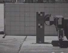
26 2.2 Test Nos. LSC-1 and LSC-2 11 Two full-scale crash tests were performed on the MGS long-span guardrail system, test nos. LSC-1 and LSC-2 [12-13]. In test no. LSC-1, the vehicle impacted the barrier near the mid-span of the unsupported length, allowing for evaluation of wheel snag, vehicle pocketing, and the potential for rail rupture. In test no. LSC-2, the vehicle impacted the barrier 3½ post spaces upstream from the unsupported span length. This test maximized the interactions between the vehicle and downstream wingwall of the culvert, thereby evaluating the potential for vehicle instabilities. Both tests showed successful performance of the MGS long-span system, but the barriers experienced more damage than seen on other MGS systems. There were CRT posts in the impact region that rotated completely out of the soil, some without fracturing, as shown in Figure 2. Figure 2. CRT Posts Rotated Out of Soil, Test No. LSC-2

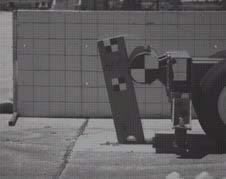
 Test No. LSC-1 (b) Test No. LSC-2 Figure 3. Guardrail Released from Posts (a) Test No.")
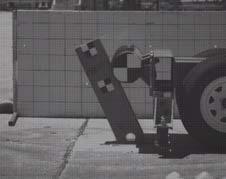
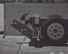
27 12 There were a considerable number of posts disengaged from the guardrail through both systems, as shown in Figure 3. In test no. LSC-1, the guardrail released from the majority of the posts downstream from the unsupported span length. Similarly, in LSC-2 the guardrail released from every post upstream from the unsupported span, including the anchors. This behavior illustrates that the MGS long-span guardrail system is sensitive to rail release. (a) Test No. LSC-1 (b) Test No. LSC-2 Figure 3. Guardrail Released from Posts (a) Test No. LSC-1 and (b) Test No. LSC-2 Both tests experienced large anchor displacements, as shown in Figure 4. In test no. LSC-1, there were 9-in (229-mm) soil gaps recorded at the downstream anchor, and in test no. LSC-2, there were 5-in. (127-mm) soil gaps recorded at the upstream anchor. Both systems had anchorages that were partially raised out of the ground.
 Upstream Anchor, Test No.")

28 13 (a) Downstream Anchor, Test No. LSC-1 (b) Upstream Anchor, Test No. LSC-2 Figure 4. Large Anchor Displacements Test Nos. LSC-1 and LSC-2
29 14 The damage imparted to the barriers during test nos. LSC-1 and LSC-2 indicated that the 25-ft (7.6-m) unsupported length may be the limit of the MGS long-span design. However, despite the posts rotating out of the soil, the considerable number of posts disengaged from the guardrail, and the large anchor displacements, both systems exhibited smooth redirection of the 2270P vehicle. Based on the successful performance of the MGS long-span design, it was speculated that the MGS long-span system could perform at the Test Level 3 conditions with unsupported span lengths in excess of 25 ft (7.6 m).
30 CHAPTER 3 DEVELOPMENT OF 25-FT MGS LONG-SPAN BASELINE 15 MODEL A finite element model of the standard MGS guardrail system was modified to develop a model of the MGS long-span system for use in culvert applications. The initial development of the MGS long span model and some of its components are outlined herein. 3.1 Midwest Guardrail System Model The standard MGS guardrail system has been successfully modeled and validated with full-scale crash testing [24-25]. This MGS model was a second-generation model which included improved end anchorages, a refined mesh for more realistic barrier deflections, and an improved vehicle-to-barrier interaction. A list of MGS model parts and associated LS-DYNA modeling parameters are shown in Table 3.
31 16 Table 3. Summary of MGS Parts and LS-DYNA Parameters [24] Part Name Anchor Cable Anchor Post Bolt Anchor Post Bolt Heads Anchor Post Washers BCT Anchor Post Bearing Plate Blockout Element Type Beam Solid Element Formulation Belytschko-Schwer, Resultant Beam Constant Stress Solid Element Material Type 6x19 ¾ in. Wire Rope ASTM A307 Material Formulation Moment, Curvature Beam Rigid Shell Belytschko-Tsay ASTM A307 Rigid Solid Solid Solid Solid Constant Stress Solid Element Fully Integrated, S/R Constant Stress Solid Element Fully Integrated, S/R ASTM F844 Wood ASTM A36 Wood Rigid Plastic Kinematic Rigid Elastic Blockout Bolts Shell Belytschko-Tsay ASTM A307 Rigid Bolt Springs Ground-Line Strut Discrete DRO=Translational Spring/Damper ASTM A307 Shell Belytschko-Tsay ASTM A36 Spring, Nonlinear Elastic Piecewise, Linear Plastic Post Soil Tubes Shell Belytschko-Tsay Equivalent Soil Rigid Soil Springs W-Beam Guardrail Section W6x9 Post Discrete Shell Shell DRO=Translational Spring/Damper Fully Integrated, Shell Element Fully Integrated, Shell Element Equivalent Soil AASHTO M180, 12-Ga. Galvanized Steel ASTM A992 Gr. 50 Spring, General Nonlinear Piecewise, Linear Plastic Piecewise, Linear Plastic P Silverado Vehicle Model A Chevrolet Silverado vehicle model (2270P), as shown in Figure 5, was used as the impacting vehicle during the initial development of the MGS long-span model. The

32 17 Silverado vehicle model was originally developed by the National Crash Analysis Center (NCAC) of The George Washington University, which was later modified by MwRSF personnel for use in roadside safety applications. This particular vehicle is a reduced version 3 Silverado model, which contains 248,915 elements, as opposed to the 930,000 elements in the detailed version 3 Silverado model. Figure 5. Reduced Chevrolet Silverado Version 3 Finite Element Model 3.3 Modeling the Long Span The initial MGS long-span model was created by omitting three posts from the center of the original MGS model, creating a 25-ft (7.6-m) long span, as shown in Figure 6. All simulation efforts were performed using metric units and, therefore, all reported dimensions in English standard units henceforth are approximations based on the metric conversions.
33 18 Figure 6. Three Steel Posts Omitted to Create 25-ft (7.6-m) Unsupported Span Length CRT Post Assembly The MGS long-span design utilizes CRT posts directly upstream and downstream from the long span. Full-scale crash testing has shown that the placement of CRT posts adjacent to the unsupported span functioned well in reducing wheel snag and pocketing [7-9, 12-13]. The CRT posts included two 3½-in. (89-mm) diameter holes drilled through the weak axis to promote fracture in those regions. These holes were located 32 and 47¾ in. (813 and 1,213 mm) from the top of the post. When the CRT posts were embedded in soil the groundline bisected the top hole of the CRT post. Thus, the bottom hole in the CRT post was completely embedded in soil. The posts were meshed with a ½-in. (12.5-mm) mesh. The region surrounding the top hole was given a failure criterion to allow fracture in that region. However, the rest of the post was constructed of the same material, but it was not given any failure criterion. This configuration improved the modeling of the wood posts. A physical wooden post will bend during loading; however, wood does not fail easily in compression. The material model used for modeling the CRT posts fails equally in compression and
34 19 tension. Therefore, to eliminate element failure outside of the fracture region of the post, the upper and lower portions of the CRT post were not given any failure criteria CRT Blockouts The CRT posts were connected to 12-in. (305-mm) deep blockouts similar to the blockouts used with the steel in-line posts. A physical CRT-blockout assembly utilizes a single guardrail bolt which connects the guardrail to the blockout and extends all the way through the blockout and CRT post. Full-scale crash testing has shown that the blockout and CRT post do not generally disengage during impact [12-13, 26-28]. This behavior allowed for the post-bolt modeling to be simplified. Instead of modeling one guardrail bolt through the entire blockout and CRT post, only the front portion, including the head of the bolt, was modeled with a rigid material. An exploded view of the complete CRT-blockout assembly is shown in Figure 7. The front of the CRT blockout was slightly modified to accommodate the simplification made in the post-bolt connection. A small section of the blockout, surrounding the bolt hole, and the guardrail bolt itself, were modeled using a rigid material. The rigid portion of the blockout was merged with the surrounding mesh of the deformable blockout. The rigid portions of the blockout and guardrail bolt were rigidly constrained together. This simplified connection at the CRT posts mimicked the guardrail-blockout connection of in-line steel posts. Finally, the back of the blockout and front of the CRT post were connected through a single merged node, in line with the guardrail bolt. The connection through a single node allowed the blockout to rotate in the same way as if it were connected with a single guardrail bolt through its center.

35 20 Figure 7. CRT Assembly - Exploded View Wood Material Model The wood material model used for the CRT posts was developed using an elastoplastic material with a failure criterion based on a maximum plastic strain. The material model was representative of Southern Yellow Pine, which is the material used in the manufacturing of CRT posts. The parameters used in the wood material model are shown in Table 4. The CRT posts were constructed of solid elements with a fully integrated, selectively reduced element formulation. Table 4. CRT Post Properties Density kg/mm 3 Young s Modulus GPa Poisson s Ratio Yield Strength GPa Tangent Modulus GPa Plastic Failure Strain E E E E-03
36 Bogie Simulations 21 Bogie simulations were used to calibrate the plastic failure criterion used in the wood material model. A bogie vehicle impacted a CRT post, constrained in a rigid sleeve, in the strong and weak axis (90 degrees from the strong axis) at a speed of 15 mph (24.1 km/h). A strong-axis bogie impact is shown in Figure 8. The CRT post s energy absorption before fracture was calibrated in both the strong and weak axes, since fullscale crash testing has shown that CRT posts fail in a combination of strong- and weakaxis bending [12-13, 26-28]. Figure 8. LS-DYNA Simulation of CRT Bogie Testing Simulation data from the bogie tests were compared against physical bogie testing data to match the energy absorption during deflection for both the weak and strong axes, as shown in Figures 9 and 10 [29]. The plastic strain failure was the only parameter changed between runs, and the simulated failure strains were 0.08, 0.10, 0.12, and A plastic failure strain of 0.12 was selected, because this value fell within the range of test data for both the strong- and weak-axis tests.
37 22 Figure 9. Energy-Deflection for CRT Posts about Strong Axis Figure 10. Energy-Deflection for CRT Posts about Weak Axis Validation The bogie simulations performed on the strong and weak axes of the CRT posts were compared against physical bogies, as shown in Figures 11 and 12, respectively.

38 Figure 11. Strong-Axis CRT Post Impact, LS-DYNA Simulation vs Bogie Test 23


39 Figure 12. Weak-Axis CRT Post Impact, LS-DYNA Simulation vs Bogie Test 24
40 25 In both strong- and weak-axis bogie tests, the posts began to facture at the groundline near the breakaway hole. The CRT post continued to rotate and lose strength as the wood fractured. Similarly, the CRT posts in the simulation began to fracture at the breakaway hole in both the strong- and weak-axis impacts. As the CRT posts rotated backwards, elements began to erode on both the front and back of the post due to tension and compression, and as the elements eroded, the post lost strength. Based on the correlation with the physical bogie tests, degrees of deflection, and modes of failure, the wood material model used for the CRT posts was considered validated CRT Soil Tubes The CRT posts, like the steel posts, rested in rigid tubes connected to discrete spring elements, which attempt to model soil resistance. The soil tubes were constrained to prevent any translation or twisting of the CRT post. The only motions allowed were the longitudinal and lateral rotations of the posts. The discrete spring elements were attached to the top of the soil tubes. These springs provided the soil resistance and followed separate loading and unloading curves. Once a physical post rotates through soil and the load is removed, the soil resistance on the post significantly decreases. Thus, separate load curves in the model provided the appropriate resistance during loading but followed a much steeper curve during unloading, which prevented the spring element from recoiling and lowered the resistance on the post. The original soil tubes had to be modified to accommodate the larger crosssection of the CRT post. In addition, the height of the soil tubes had to be increased to just below the top hole in the CRT post. The increased height of the soil tubes helped promote fracture at the top hole in the CRT post. The soil tubes were not raised to the

41 26 height of the groundline, because they were only meant to promote failure in the fracture region of the posts. They were not meant to provide a precise fracture line through a specific region of the post. The fracture location of the CRT post was a function of the soil tube height. Therefore, it was necessary to increase the height of the soil tube, such that it promoted fracture in the region of the post that was consistent with fracture observed in physical testing. Once the CRT posts were developed, the blockouts were connected, the soil tubes were modified, and the CRT post assemblies were then implemented into the MGS system. The MGS long-span design contains a total of six CRT posts directly adjacent to the unsupported span. Thus, CRT posts replaced three steel in-line posts on either side of the unsupported span, as shown in Figure 13. Figure 13. MGS Long-Span with CRT Posts Adjacent to Unsupported Span Implementation of Culvert and Ground Profile There were two full-scale tests performed on the MGS long-span guardrail system, and due to the nature of the tests, slightly different culverts were constructed for each. As a result of the different culvert structures, the surrounding ground profiles had to be developed separately as well.
, with the wingwall flared at 45 degrees, as shown in Figure 14.")
42 Test No. LSC-1 Configuration 27 Test no. LSC-1 contained a single wingwall culvert that was 9 in. (229 mm) thick and spanned a total distance of 23 ft 11 in. (7.3 m), with the wingwall flared at 45 degrees, as shown in Figure 14. This test impacted the system near the center of the unsupported span length, and therefore the upstream portion of the culvert was inconsequential. The culvert was constructed from rigid shell elements with a 2.0-in x 2.0-in. (50-mm x 50-mm) mesh used to capture the chamfered edge along the top of the culvert. The culvert was assigned concrete material properties. Figure 14. Single Wingwall Culvert, Test No. LSC-1 Due to the impact location in test no. LSC-1, the vehicle only interacted with the downstream wingwall as it exited the system. Since the vehicle never interacted with the ground upstream of the culvert nor penetrated past the farthest point of the culvert, it was unnecessary to model any sloping ground contours. Thus, a simple ground configuration composed of finite planar rigidwalls was sufficient, as shown in Figure 15.

, as shown in Figure 16. Similarly, the culvert was constructed from rigid shell elements with a 2.0-in")
43 28 Figure 15. Test No. LSC-1 Ground Profile Constructed from Finite Planar Rigidwalls Test No. LSC-2 Configuration Test no. LSC-2 used a double wingwall culvert, which had a 9-in. (229-mm) thick head wall with both the upstream and downstream wingwalls flared at 45 degrees for a total length of 30 ft 3 in. (9.2 m), as shown in Figure 16. Similarly, the culvert was constructed from rigid shell elements with a 2.0-in x 2.0-in. (50-mm x 50-mm) mesh and assigned concrete material properties. Figure 16. Double Wingwall Culvert, Test No. LSC-2
 behind the back face of the guardrail posts, and the wingwalls were modified to match the soil slope [12-13].")
44 29 The ground profile used to model test no. LSC-2 was more complex than that used with the single wingwall culvert. In test no. LCS-2, the ground had a 3H:1V slope that started 24.0 in. (610 mm) behind the back face of the guardrail posts, and the wingwalls were modified to match the soil slope [12-13]. The choice of the slope profile was based on choosing the flattest slope of the typical culvert installations submitted by the sponsoring states at the time. The choice of the flattest slope maximized the potential for vehicle interaction with the wingwalls of the culvert during the impact event. Development of the ground profile around the double wingwall culvert was too complex to accomplish using finite planar rigidwalls. A series of contours, composed of rigid shell elements, shaped the ground around the double wingwall culvert, as shown in Figure 17. The contact between the ground shells and vehicle tires was achieved using the *CONTACT_ENTITY definition. This contact definition treated impacts between deformable bodies and rigid bodies with a penalty formulation, which was analogous to the rigidwall contact formulation used to model test no. LSC-1. Figure 17. Test No. LSC-2 Ground Profile Constructed from Shell Elements

45 3.3.3 Modeling Issues 30 During the development of the MGS long-span model, specific modeling issues occurred which required careful consideration. This section documents the issues encountered in generating the CRT post assemblies and the techniques taken to address them CRT Post-Blockout Connection As the CRT posts fractured and began releasing from the rail, the blockouts began to separate from the CRT posts due to the simplifications made in the blockout connection. The CRT post was constructed with a significantly finer mesh than the blockout. As a result, the blockout mesh was much stiffer than the CRT post mesh. This change caused the post mesh to distort unrealistically as the blockout attempted to separate from the post, as shown in Figure 18. Figure 18. Unrealistic CRT Post-Blockout Separation A material modification was made to stiffen the region of the CRT post used in the connection with the blockout. This modification was accomplished by increasing the

46 31 density and elastic modulus for the four solid elements surrounding the node used in the blockout connection. These parameters were increased enough to prevent the elements from distorting and mimicked the properties of steel. The locations of the elements used in this attachment modification are shown in Figure 19. This modification still allowed rotation of the blockout, but it did not allow any post-blockout separation. Figure 19. CRT Post-Blockout Attachment Modification Fracture Region of CRT Posts The soil model consists of discrete spring elements (soil springs) and soil tubes. The soil tubes are a way of connecting posts to soil springs to prevent post translation and twist. The top of the soil tubes surrounding the CRT posts presented a sharp edge in the fracture region of the post. This edge resulted in poor contact behavior, as seen by the excessive penetration of the CRT post through the back side of the soil tube, as shown in Figure 20. Interpenetration between the soil tube and CRT post could cause a local lockup between parts, which would prevent the post from sliding along that edge. This
47 32 contact was initially modeled with a *CONTACT_AUTOMATIC_SURFACE_ TO_SURFACE contact definition. Contact between the CRT post and soil tube would register and prevent penetrations if the outermost surface of the post contacted the soil tube. However, once the outer elements on the back side of the post reached their plastic strain failure, the elements would delete, exposing the inner layer of elements. The inner elements did not have contact defined with the soil tube under this contact definition, and thus, excessive penetration of the soil tube ensued. Figure 20. CRT Post Soil Tube Contact Interference The contact between the post and soil tube had to include the elements on the surface of the post as well as the inner elements of the post. As the outer elements reached their plastic strain failure limit and deleted, the inner elements were exposed to the soil tube. Therefore, it was important that these new elements be included in the contact definition between the post and soil tube to keep the soil tube from penetrating through the post. A *CONTACT_ERODING_SINGLE_SURFACE contact definition was implemented to remedy the contact issue. In the eroding single-surface contact, the
48 33 contact surface updates as elements on the free surface are deleted according to the material failure criterion. Therefore, once the contact surface was updated, the new layer of elements were considered in the contact defined between the CRT post and soil tube, and the excessive penetrations of the soil tube into the post were reduced, as shown in Figure 21. Figure 21. New Contact Definition in Fracture Region of CRT Post. Although the eroding single-surface contact definition significantly improved the contact, some penetration of the soil tube into the CRT post was still present. The top of the soil tube provided a sharp edge, and that type of contact penetration is typical under those conditions. The interpenetration of the soil tube and CRT post was ultimately corrected by rounding off the top edge of the soil tube, thus preventing the sharp edge from digging into the post. A ½-in. (12.5-mm) radius lip was added to the top of the soil tube, as shown in Figure 22. The removal of the sharp edge in the contact region eliminated all excessive penetrations between the soil tube and CRT post.
 Radius Lip around Top Edge of")
49 Figure 22. 1/2-in. (12.5-mm) Radius Lip around Top Edge of Soil Tube 34

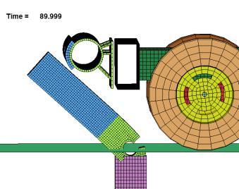
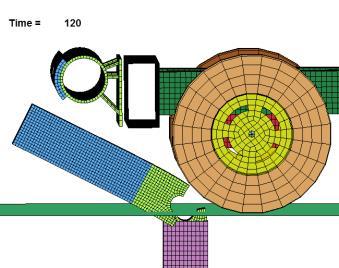
50 CHAPTER 4 SIMULATING TEST NOS. LSC-1 AND LSC Correlation between Baseline Models and Full-Scale Crash Tests Once baseline models of the MGS long-span were developed, the simulation results were compared against full-scale crash test nos. LSC-1 and LSC-2. In addition to a visual analysis, the velocity profiles, maximum barrier deflections, maximum pocketing angles, and occupant risk values were used to evaluate the baseline simulations. A post-numbering convention was developed for the MGS long-span design that will become more important as in-line posts are removed during the investigation of increased span lengths. However, to maintain consistency, the post-numbering convention will be introduced here and maintained throughout the remainder of this study, as shown in Figure 23. The in-line posts are numbered from the unsupported length to the anchors. Posts upstream from the unsupported length are denoted (US-P#), and similarly the posts downstream are denoted (DS-#). Missing post locations throughout the unsupported length are denoted (MP#). Figure 23. Post Numbering Convention for MGS Long-Span Design The impact locations for the baseline models occurred 17 ft (5.2 m) upstream from post no. DS-P1 for test no. LSC-1, and 28 in. (711 mm) downstream from post no. US-P4 for test no. LSC-2, as shown in Figure 24. If the simulations correlate to tests nos.

51 36 LSC-1 and LSC-2, the baseline models can then be modified to develop longer unsupported spans. Those simulations will be used to draw reasonable conclusions about the MGS long-span system at increased span lengths. Figure 24. Impact Locations Test Nos. LSC-1 and LSC Graphical Comparison Sequentials of test nos. LSC-1 and LSC-2, along with their corresponding baseline simulations, are presented in Figures 25 through 28, respectively. The LSC-1 baseline model accurately captured the vehicle and system behavior exhibited in the fullscale crash test. The vehicle in the simulation did exit the system sooner than the vehicle in the full-scale test, which produced some discrepancies in the guardrail and vehicle behavior after 600 ms. By that time, the vehicle had already been redirected. In the LSC-2 baseline model, there were noticeable differences in vehicle behavior and barrier deflections. The rear of the vehicle in the full-scale crash test dropped down below the culvert headwall as the vehicle redirected. However, in the LSC-2 baseline simulation, the rear of the vehicle pitched upward; the effects were most noticeable at the 520, 610, and 700 ms markers. In addition, the simulation did not accurately capture the barrier deflections or vehicle extent over the culvert.


52 37 0 ms 0 ms 106 ms 100 ms 214 ms 210 ms 300 ms 300 ms Figure 25. Test No. LSC-1 and Baseline LS-DYNA Simulation Sequentials

53 ms 410 ms 520 ms 520 ms 610 ms 610 ms 700 ms 700 ms Figure 26. Test No. LSC-1 and Baseline LS-DYNA Simulation Sequentials (continued)

54 39 0 ms 0 ms 130 ms 130 ms 208 ms 210 ms 302 ms 300 ms Figure 27. Test No. LSC-2 and Baseline LS-DYNA Simulation Sequentials
55 ms 420 ms 524 ms 520 ms 600 ms 600 ms 700 ms 700 ms Figure 28. Test No. LSC-2 and Baseline LS-DYNA Simulation Sequentials (continued)
56 41 In test no. LSC-1, the guardrail disengaged from several of the in-line posts downstream from the culvert. The degree of guardrail disengagement observed in test no. LSC-1 was accurately predicted by the LSC-1 baseline model. However, the number of in-line posts that disengaged from the guardrail was considerably higher in test no. LSC-2 than in test no. LSC-1, as every post upstream from the unsupported length disengaged from the guardrail. This phenomenon was not predicted by the LSC-2 baseline model. In the LSC-2 baseline simulation, only four in-line posts disengaged from the guardrail downstream from the unsupported length Velocity Profiles Velocity profiles from onboard transducers were compared between the vehicles in the baseline simulations and test nos. LSC-1 and LSC-2, as shown in Figures 29 and 30, respectively. The longitudinal and lateral accelerations from the simulations were processed the same as the accelerometer data obtained from the full-scale tests to ensure the curves were comparable. The longitudinal velocity comparisons between the baseline simulation and test no. LSC-1 matched the closest. Overall, the simulations tended to underpredict the change in longitudinal velocity and overpredict the change in lateral velocity.
57 42 Figure 29. Velocity Profile Comparisons, Baseline Simulation and Test No. LSC-1 Figure 30. Velocity Profile Comparisons, Baseline Simulation and Test No. LSC-2 The difference in velocities was based on how the systems absorbed the impact energy. As seen in test nos. LSC-1 and LSC-2, there were CRT posts that rotated out of the soil without fracturing. It is not possible to simulate the soil and wood post behavior
58 43 with a high degree of correlation using current modeling techniques. In the simulation, the CRT posts fractured earlier in the event and out in front of the vehicle. Once the CRT posts fractured, they no longer provided any resistive force. During the full-scale test, the CRT posts rotated in the soil, providing a lower resistive force over a longer duration of time. Thus, the CRT posts in the physical test may have absorbed more energy than the CRT posts in the simulation. In the physical test, the guardrail wrapped itself around the front corner of the vehicle more so than in the simulations, because the CRT posts did not fracture out in front of the vehicle. This phenomenon is known as pocketing and resulted in higher longitudinal decelerations Barrier Deflections The maximum dynamic deflections recorded during the full-scale crash tests and baseline simulations are shown in Table 5. Both simulations underpredicted the dynamic deflections obtained in test nos. LSC-1 and LSC-2. The LSC-1 baseline model underpredicted the maximum dynamic deflection by 21.4 percent, and the LSC-2 baseline model underpredicted the maximum dynamic deflection by 29.4 percent. Table 5. Maximum Dynamic Deflections - Baseline Models Test No./ Simulation Maximum Dynamic Deflection in. (mm) Full-Scale Crash Tests LSC (2,343) LSC (1,968) Simulations LSC (1,843) LSC (1,390)
59 44 Significant differences in the dynamic deflections are likely attributed to the softer soil conditions and large anchor displacements obtained in the full-scale crash tests. Although test nos. LSC-1 and LSC-2 used soil compaction methods within the standards at the time, the tests did not use the current soil strength requirements that are contained in MASH [14]. Thus, the soil compaction methods employed at the time of test nos. LSC-1 and LSC-2 were not as consistent as the current standard. As a result, the fullscale crash tests performed on the MGS long-span system exhibited lower post-soil resistive forces, which played a factor in the barrier damage and barrier deflections observed during those tests. In contrast, the current LS-DYNA model of the MGS was validated against full-scale crash tests [24-25] that were performed using the current soil standard in MASH Pocketing Angles Maximum pocketing angles measured for the baseline simulations and full-scale crash tests are presented in Table 6 and Figure 31. Both simulations underpredicted the maximum pocketing angles obtained in test nos. LSC-1 and LSC-2. The LSC-1 baseline model underpredicted the maximum pocketing angle by 28.2 percent, or 7 degrees, and the LSC-2 baseline model underpredicted the maximum pocketing angle by 11.1 percent, or 3 degrees. The LSC-2 baseline simulation accurately predicted the time and location of the pocketing. The maximum pocketing angles measured in both the full-scale crash tests and baseline simulations were within the limit recommended by the researchers at MwRSF. A study on MGS transition systems suggested that the critical pocketing angle for the 2270P vehicle may be as high as 30 degrees [30-31].
60 Table 6. Maximum Pocketing Angles - Baseline Models 45 Test No./ Simulation Pocketing Angle Time (ms) Location Full-Scale Crash Tests LSC Upstream from DS-P4 LSC Upstream from DS-P2 Simulations LSC Upstream from DS-P3 LSC Upstream from DS-P2 Recommended Limit 30.0 Discrepancies in the maximum pocketing angles can be attributed to the behavior of the CRT posts. In the full-scale tests, the CRT posts rotated backward in the soil and did not fracture as far out in front of the vehicle as the CRT posts did in the simulations. Therefore, larger pocketing angles developed as the vehicle approached the CRT posts in the full-scale crash tests. Since the wood posts fractured well in front of the vehicle in the baseline simulations, the pockets were unable to develop large pocketing angles.

 in both the longitudinal and lateral directions")


61 46 (a) LSC-1 (b) LSC-2 Figure 31. LS-DYNA Baseline Models: Pocketing Angle Comparisons Occupant Risk The calculated occupant impact velocities (OIVs) and occupant ridedown accelerations (ORAs) in both the longitudinal and lateral directions for the baseline simulations and test nos. LSC-1 and LSC-2 are shown in Table 7. The baseline simulations overpredicted the OIVs and ORAs in every case except the longitudinal OIV recorded in test no. LSC-2, which produced the largest discrepancy. However, despite these differences, the occupant risk values were comparable between the simulations and full-scale tests.
62 Table 7. Occupant Risk Values - Baseline Models 47 Test No./ Simulation OIV ft/s (m/s) ORA g's Longitudinal Lateral Longitudinal Lateral Full-Scale Crash Test LSC (-2.92) (3.23) LSC (-4.90) (4.09) Simulation LSC (-3.32) (-4.14) LSC (-3.21) (-4.07) MASH Limits 40 (12.2) 40 (12.2) Discussion Several metrics, including a visual analysis and comparisons between velocity profiles, barrier deflections, pocketing angles, and occupant risk values, were used to evaluate the baseline MGS long-span simulations against full-scale crash test nos. LSC-1 and LSC-2. The LSC-1 and LSC-2 baseline simulations produced results that were comparable with the full-scale crash tests. However, there were significant modeling assumptions that resulted in discrepancies between simulations and full-scale tests. The post-in-soil modeling technique could not capture the behavior observed in full-scale crash testing. Since the simulations could not capture the behavior of the CRT posts rotating out of the ground, the pocketing observed in test nos. LSC-1 and LSC-2 was underpredicted by the baseline simulations. Similarly, the behavior of the CRT posts
63 48 influenced the longitudinal and lateral velocity profiles. In addition, the simulations could not recreate the large soil gaps around the anchorages recorded in the physical tests, which helped reduce the maximum barrier deflections predicted by the baseline simulations. A significant amount of guardrail disengaged away from the in-line posts during both full-scale tests. The LSC-1 baseline model accurately predicted the degree of rail release observed in test no. LSC-1, but the LSC-2 baseline model only predicted four disengaged posts. The guardrail-to-post connection was not detailed enough in the MGS long-span model to capture the amount of guardrail disengaged in test no. LSC-2. The current bolted connection technique was sufficient for the base MGS model, but the attachment was sensitive to the long-span system. This result prompted an investigation into the modeling of the bolted connections between the guardrail and posts. Details on developing an improved bolted connection between the post and guardrail is presented in Chapter 8. Simulating test nos. LSC-1 and LSC-2 with a high degree of correlation was impossible due to the modeling limitations presented. However, the velocity profiles predicted by the simulations were still relatively close to the velocity profiles produced during the full-scale tests. Similarly, even though the simulations underpredicted the maximum barrier deflections, the overall redirection of the vehicle was similar to the redirections observed in test nos. LSC-1 and LSC-2. The occupant risk values compared well between the simulations and full-scale tests, and the maximum pocketing angle predicted by the LSC-2 baseline simulation closely matched the pocketing observed in the full-scale test. Therefore, despite some discrepancies between the baseline
64 49 simulations and test nos. LSC-1 and LSC-2, these models can be used to modify the current long-span design and draw reasonable conclusions about the performance of the MGS long-span system.

65 CHAPTER 5 SELECTION OF A 2270P VEHICLE MODEL 50 The vehicle model used to evaluate the MGS long-span system was the Chevy Silverado truck developed by NCAC. Three different versions of the Silverado model were investigated to determine which model most accurately represented the vehicle behavior and system response observed during the full-scale crash test no. LSC-2. The three Silverado models were the Silverado Version 2 (Silverado-v2), Version 3 (Silverado-v3), and reduced Version 3 (Silverado-v3r), as shown in Figure 32. Figure 32. Numerical Silverado Models There are advantages and disadvantages associated with each of the vehicle models. For example, the Silverado-v3 and -v3r models have steering while the Silverado-v2 does not. The Silverado-v2 has a softer tire model that more accurately captures the behavior of a physical tire; however, this tire model can lead to contact instabilities if the tires experience significant deformation. The Silverado-v3 and -v3r have a stiffer tire model that is more robust to contact instabilities, but it can correspond to an exaggerated response during impact. The Silverado-v3r has significantly fewer elements than the Silverado-v2 or -v3, which leads to considerably lower computation times. Detailed information on these vehicle models can be found on NCAC s website [32].
66 5.1 Simulation Cases 51 There were a total of six different simulation cases performed with the three Silverado models. In test no. LSC-2 during redirection, the left-front tire disengaged as the vehicle interacted with the downstream wingwall of the culvert. To capture this behavior, it was assumed that the left-front tire would disengage as it impacted the downstream wingwall of the culvert. Thus, the Silverado models were evaluated with suspension failure for the LSC-2 impact location. The six simulation cases were as follows: Silverado Version 2 (V2) Silverado Version 2 with Left-Front Tire Suspension Failure (V2-SF) Silverado Version 3 (V3) Silverado Version 3 with Left-Front Tire Suspension Failure (V3-SF) Reduced Silverado Version 3 (V3R) Reduced Silverado Version 3 with Left-Front Tire Suspension Failure (V3R-SF) Simulating suspension failure is accomplished by terminating the joints that connect to the tire once the forces in those joints increase considerably due to an impact event. The forces at which those joints realistically fail are unknown, and, therefore, simulating suspension failure is not predictive modeling. However, suspension failure can be used as a tool to obtain stronger correlation with physical testing where tire disengagement had occurred. Since modeling tire disengagement is not actually predictive failure, this technique is used sparingly and with caution.
67 5.2 Correlation between Silverado Models and Test No. LSC-2 52 The Silverado cases were simulated at the LSC-2 critical impact location and compared against the full-scale crash test. Various metrics, including a visual analysis and comparisons of velocity profiles, barrier deflections, pocketing angles, vehicle behavior, and occupant risk values, were used to evaluate each Silverado vehicle model. Test no. LSC-2 was chosen due to the interactions with the culvert and potential for vehicle instabilities Graphical Comparison Sequentials of each Silverado case, compared to test no. LSC-2, are shown in Figures 33 through 38. The barrier did not deflect as far in the simulations, and the simulated vehicles did not drop down over the culvert, as the physical vehicle did in the full-scale crash test. Out of these cases, the Silverado-v3r-SF showed the highest degree of visual correlation with test no. LSC-2. The Silverado-v2 simulation without suspension failure terminated at 540 ms due to contact instabilities. This result occurred as the left-front tire was contacting the downstream wingwall and was likely a result of the softer tire model. A close-up comparison at the moment of impact with the downstream wingwall of the culvert is presented in Figure 39. There was strong contact with the wingwall in both Silverado-v2 cases. Since there was no steering in the Silverado-v2 model, the left-front tire was squared up with the wingwall during impact. Conversely, in the Silverado-v3 and v3r models with steering, the tire was turned, which resulted in a less severe, glancing impact into the downstream wingwall. In the Silverado-v3r-SF, the upper and lower control arms connecting the left-front tire fractured due to contact with the upstream CRT
68 53 posts. This behavior allowed the left-front tire to drop down below the culvert headwall as the vehicle traversed the unsupported span. The case of the Silverado-v3r-SF provided the highest degree of contact with the downstream wingwall and most accurately represented what occurred in the physical test.
69 54 0 ms 0 ms 200 ms 200 ms 400 ms 400 ms 600 ms 540 ms Figure 33. Sequentials Test No. LSC-2 and LS-DYNA Simulation, Silverado-v2
70 55 0 ms 0 ms 200 ms 200 ms 400 ms 400 ms 600 ms 600 ms 800 ms 800 ms Figure 34. Sequentials Test No. LSC-2 and LS-DYNA Simulation, Silverado-v2-SF
71 56 0 ms 0 ms 200 ms 200 ms 400 ms 400 ms 600 ms 600 ms 800 ms 800 ms Figure 35. Sequentials Test No. LSC-2 and LS-DYNA Simulation, Silverado-v3
72 57 0 ms 0 ms 200 ms 200 ms 400 ms 400 ms 600 ms 600 ms 800 ms 800 ms Figure 36. Sequentials Test No. LSC-2 and LS-DYNA Simulation, Silverado-v3-SF

73 58 0 ms 0 ms 200 ms 200 ms 400 ms 400 ms 600 ms 600 ms 800 ms 800 ms Figure 37. Sequentials Test No. LSC-2 and LS-DYNA Simulation, Silverado-v3r

74 59 0 ms 0 ms 200 ms 200 ms 400 ms 400 ms 600 ms 600 ms 800 ms 800 ms Figure 38. Sequentials Test No. LSC-2 and LS-DYNA Simulation, Silverado-v3r-SF


75 60 Test No. LSC-2 Silverado-v2 Silverado-v3 Silverado-v3r (a) No Suspension Failure (b) Suspension Failure Figure 39. Impact Comparisons with Downstream Culvert Wingwall, Silverado Models
76 61 A contact issue between the left-front tire and the upstream wingwall of the culvert was discovered during the analysis of the Silverado models. The left-front tire of the simulated vehicle tended to ramp the upstream wingwall due to a contact thickness differential between the shell elements that made up the ground and the shell elements that made up the culvert. The difference in contact thicknesses, combined with the stiffer tire model associated with the Silverado-v3r, caused the truck to ramp the wingwall and prevented it from dropping down into the culvert. The difference in contact thickness was corrected by including the ground and culvert in a single contact definition. Further discussion on modeling the ground contacts is presented in Chapter Velocity Profiles The longitudinal changes in velocity from all six simulation cases were compared against transducer data obtained during test no. LSC-2, as shown in Figure 40. The longitudinal accelerations from each of the simulation cases were processed the same as the accelerometer data obtained from the full-scale test to ensure the curves were comparable. Out of all the simulation cases, the Silverado-v3r-SF had a longitudinal velocity profile that most closely matched that observed in the full-scale test. Overall, there was a larger drop in the longitudinal velocity during the full-scale test than observed in the simulation cases.
77 62 Figure 40. Longitudinal Velocity Profiles, Silverado Models and Test No. LSC Barrier Deflections Maximum barrier deflections were recorded for each of the simulation cases and compared against the full-scale test, as shown in Table 8. The maximum dynamic deflection measured in test no. LSC-2 was 77.5 in. (1,968 mm), whereas the maximum dynamic deflection recorded from the simulation cases was only 63.0 in (1,599 mm) with the Silverado-v3, a difference of 19 percent. The barrier deflections compared well between vehicle models with less than a 2-in. (50-mm) difference between the cases. There were larger anchor deflections observed in the full-scale test that were not present in the simulations, likely due to the simplified soil model. In addition, the simulated vehicle did not drop down below the culvert headwall in the simulations as observed in the physical vehicle for the full-scale crash test. These factors contributed to the larger dynamic deflections measured in test no. LSC-2 as compared to the barrier deflections obtained in these simulation cases.
78 Table 8. Maximum Dynamic Deflections - Silverado Models 63 Test No. / Silverado Model Maximum Dynamic Deflection in. (mm) Full-Scale Crash Test LSC (1,968) Simulations V (1,578) V2-SF 62.6 (1,591) V (1,599) V3-SF 61.9 (1,572) V3R 61.0 (1,550) V3R-SF 61.7 (1,551) Pocketing Angles Maximum pocketing angles and locations were calculated for each of the simulation cases and compared to overhead film footage of test no. LSC-1, as shown in Table 9 and Figure 41. The maximum pocketing angle obtained with the Silverado-v3 had nearly the exact same pocketing angle as test no. LSC-2, with less than 1 percent difference. Similarly, the pocketing angles obtained with the Silverado-v3r in both cases, with and without suspension failure, matched the test within 2 degrees. Maximum pocketing angles for these three cases occurred at the same post location as the physical test and at approximately the same time after impact. The high degree of correlation in the maximum pocketing angles can be seen from the overhead comparison.
79 64 Table 9. Maximum Pocketing Angles - Silverado Models Test No./ Silverado Model Pocketing Angle Time (ms) Full-Scale Crash Test Location LSC Upstream from DS-P2 Simulations V Upstream from US-P2 V2-SF Upstream from DS-P3 V Upstream from DS-P2 V3-SF Upstream from DS-P3 V3R Upstream from DS-P2 V3R-SF Upstream from DS-P2 Recommended Limit 30.0

 No Suspension")


80 65 Test No. LSC-2 Silverado-v2 Silverado-v3 Silverado-v3r (a) No Suspension Failure (b) Suspension Failure Figure 41. Pocketing Comparison, Silverado Models
81 5.2.5 Vehicle Stability 66 The vehicle dynamics and parallel times recorded for each simulation case and test no. LSC-2 are shown in Table 10 and compared in Figures 42 through 44. The simulation cases captured the maximum pitch and roll angles of the physical vehicle in test no. LSC-2 to within a few degrees. The simulations tended to overpredict the vehicle roll motion into and away from the barrier as the vehicle traversed the culvert and exited the system, respectively. None of the vehicle models accurately simulated the vehicle dropping down below the culvert headwall as observed in the full-scale crash test. As a result, the simulations did not fully capture the pitch behavior as the vehicle rode up and out of the culvert. The simulations did accurately capture the yaw motion of the vehicle up through the parallel times, but began to diverge as the vehicle exited the system. Discrepancies in the vehicle behavior can be partially attributed to simplifications made in the vehicle suspension components, which make it difficult to simulate vehicle dynamics with a high degree of correlation.
82 Table 10. Vehicle Behavior - Silverado Models 67 Test No./ Silverado Model Roll Angle Pitch Angle Full-Scale Crash Test Yaw Angle Parallel Time (ms) LSC Simulations V V2-SF V V3-SF V3R V3R-SF MASH Limits < 75 < 75 N/A Maximum value not reached prior to conclusion of simulation. Figure 42. Vehicle Roll Angle, Silverado Models and Test No. LSC-2
83 68 Figure 43. Vehicle Pitch Angle, Silverado Models and Test No. LSC-2 Figure 44. Vehicle Yaw Angle, Silverado Models and Test No. LSC Occupant Risk The calculated occupant impact velocities (OIVs) and occupant ridedown accelerations (ORAs) in both the longitudinal and lateral directions are shown in Table
84 The Silverado-v3r-SF had the closest longitudinal OIV and ORA, and similar lateral ORA values, as compared to test no. LSC-2. There were difficulties obtaining lateral accelerations from the onboard accelerometers in each of the vehicle models that were comparable to test no. LSC-2. As a result, the lateral velocity traces and lateral OIVs did not correlate well with the transducer data obtained during the full-scale crash test. Table 11. Occupant Risk Values - Silverado Models Test No./ Silverado Model OIV ft/s (m/s) ORA g's Longitudinal Lateral Longitudinal Lateral Full-Scale Crash Test LSC (-4.90) (4.09) Simulations V (-4.58) 2.59 (0.79) V2-SF (-4.43) 2.43 (0.74) V (-4.68) 2.76 (0.84) V3-SF (-4.50) 2.72 (0.83) V3R (-4.62) 1.54 (0.47) V3R-SF (-4.98) 1.94 (0.59) MASH Limits 40 (12.2) 40 (12.2) Discussion Various metrics, including a visual analysis and comparisons of velocity profiles, barrier deflections, pocketing angles, vehicle behavior, and occupant risk values, were
85 70 used to evaluate each of the three Silverado vehicle models. The MGS long-span model did not accurately predict the maximum barrier deflections measured in test no. LSC-2 with any of the Silverado models. The larger anchor displacements observed in the fullscale test were not present in the simulations, due to the simplified soil model. In addition, the simulated vehicle did not drop down below the culvert headwall to the same degree in the simulations as observed in the full-scale crash test, which resulted in different vehicle kinematics. Overall, the simulations did predict the same general behavior of the physical vehicle, but it overpredicted roll angle and underpredicted pitch angle as the simulated vehicle traversed and exited the culvert, respectively. The Silverado-v3 model had the highest barrier deflections and predicted a maximum pocketing angle that was within 1 percent of the calculated pocketing angle for test no. LSC-2. Although the Silverado-v3 model had the highest barrier deflections, the range of maximum barrier deflections predicted by all six simulations were within 2 in. (51 mm) and at least 19 percent lower than the deflections observed in the full-scale crash test. Based on the evaluated metrics, the Silverado-v3r-SF model most accurately represented the vehicle behavior and system response observed in test no. LSC-2. The Silverado-v3r-SF had the closest redirection behavior based on the graphical comparison and longitudinal velocity profile. In addition, the Silverado-v3r-SF most accurately captured the interactions between the vehicle and the downstream wingwall of the culvert. This model predicted a maximum pocketing angle within 2 degrees, at the same time and at the same post location as test no. LSC-2. The ORA and longitudinal OIV values calculated for the Silverado-v3r-SF correlated with the full-scale crash test better
86 71 than any of the other simulations. Overall, the Silverado-v3r model contains less than a third of the elements as the Silverado-v3 model, which allowed for considerably faster computation times. It is therefore recommended that the Silverado-v3r with suspension failure be used for simulations involving the MGS long-span model.
87 CHAPTER 6 INCREASED SPAN LENGTHS OF THE MGS LONG-SPAN Development of Longer Span Lengths Once the 25-ft (7.6-m) MGS long-span baseline model was developed and a suitable Silverado vehicle model was selected, increased span lengths of the MGS longspan design were evaluated. The LSC-2 baseline model was selected to investigate longer span lengths because the culvert geometry was suitable for impacts located anywhere along the system. The culvert design in the LSC-1 baseline model did not contain an upstream wingwall or the 3H:1V slope that maximized the potential for vehicle interaction with the wingwalls of the culvert. Increased span lengths of 31¼ ft, 37½ ft, 43¾ ft, and 50 ft (9.5 m, 11.4 m, 13.3 m, and 15.2 m) were developed by removing an in-line steel post and shifting the three CRT posts. This ensured that three CRT posts remained adjacent to the unsupported length on either side. The removal of in-line posts alternated between occurring downstream and upstream from the unsupported length for each new span length. This helped maintain symmetry within the system and attempted to evenly distribute the load during redirection. 6.2 Analysis of 25-ft, 31¼-ft, and 37½-ft MGS Long-Span Systems Initial investigations into the increased span length for the MGS long-span design looked at removing one to two additional posts to create a 31¼-ft and 37½-ft (9.5-m and 11.4-m) unsupported span length, respectively. The 31¼-ft and 37½-ft (9.5-m and m) span systems were compared against the baseline 25-ft (7.6-m) span system to determine the effects of longer unsupported span lengths. These systems were evaluated at the Test Level 3 (TL-3) impact conditions, 62 mph (100.0 km/h) and 25 degrees, using
![73 the critical impact points that were determined for test nos. LSC-1 and LSC-2 [12-13].](/docs-images/93/112896974/images/88-0.jpg "Other impact locations were investigated, but they revealed no further insight into the behavior of these three systems.")
88 73 the critical impact points that were determined for test nos. LSC-1 and LSC-2 [12-13]. Other impact locations were investigated, but they revealed no further insight into the behavior of these three systems. A total of six cases were investigated, with three span lengths and two different impact locations, as shown in Figure 45. Suspension failure was only implemented at the LSC-2 impact location due to interactions with the wingwall of the culvert. Impacts at the LSC-1 impact location did not assure tire disengagement and, therefore, suspension failure was not implemented in those simulations. Figure 45. Simulation Cases for 25-ft (7.6-m), 31¼-ft (9.5-m), and 37½-ft (11.4-m) Spans Graphical Comparisons The 25-ft, 31¼-ft, and 37½-ft (7.6-m, 9.5-m, and 11.4-m) span systems successfully and smoothly redirected the 2270P vehicle at both the LSC-1 and LSC-2 impact locations. In general, as the unsupported span length increased, there was a higher level of barrier damage, as shown in Figures 46 through 51. In the 31¼-ft and 37½-ft (9.5-m and 11.4-m) span systems and using the LSC-1 impact location, the guardrail
89 74 disengaged from every post downstream from the culvert, and the downstream inner BCT post fractured in both systems. Overall, the vehicle behavior during redirection was acceptable, and there was no indication of potential vehicle instabilities in any of the cases.
90 75 0 ms 500 ms 100 ms 600 ms 200 ms 700 ms 300 ms 800 ms 400 ms Figure 46. Sequentials LS-DYNA Simulation, 25-ft (7.6-m) Span, LSC-1 Impact Point
91 76 0 ms 500 ms 100 ms 600 ms 200 ms 700 ms 300 ms 800 ms 400 ms Figure 47. Sequentials LS-DYNA Simulation, 25-ft (7.6-m) Span, LSC-2 Impact Point
92 77 0 ms 500 ms 100 ms 600 ms 200 ms 700 ms 300 ms 800 ms 400 ms Figure 48. Sequentials LS-DYNA Simulation, 31¼-ft (9.5-m) Span, LSC-1 Impact Point
93 78 0 ms 500 ms 100 ms 600 ms 200 ms 700 ms 300 ms 800 ms 400 ms Figure 49. Sequentials LS-DYNA Simulation, 31¼-ft (9.5-m) Span, LSC-2 Impact Point
 Span, LSC-1 Impact Point")
94 79 0 ms 500 ms 100 ms 600 ms 200 ms 700 ms 300 ms 800 ms 400 ms Figure 50. Sequentials LS-DYNA Simulation, 37½-ft (11.4-m) Span, LSC-1 Impact Point
95 80 0 ms 500 ms 100 ms 600 ms 200 ms 700 ms 300 ms 800 ms 400 ms Figure 51. Sequentials LS-DYNA Simulation, 37½-ft (11.4-m) Span, LSC-2 Impact Point
96 81 A contact issue between the left-rear tire and the upstream wingwall of the culvert was discovered during the analysis of the MGS at increased span lengths. The rear of the simulated vehicle tended to ramp the upstream wingwall due to the ground contours around the culvert, the geometry of the culvert wingwall, and the stiffer tire models associated with the Silverado-v3r. As a result, the rear of the vehicle did not drop down into the culvert as it traversed the unsupported span. To correct the exaggerated interaction between the left-rear tire and wingwall, a separate contact definition was defined between these two parts. Further discussion on modeling the ground contacts is presented in Chapter Vehicle Stability The vehicle dynamics associated with each of the span lengths were well within the limits set in MASH. There were no discernable differences in the vehicle roll and pitch values with respect to span length; however, the yaw angles and parallel times did increase with increased span length, as shown in Table 12. With an increase in span length, the unsupported region of the guardrail system became softer, and the vehicle was able to penetrate farther into the barrier before redirecting, which led to later parallel times. Higher roll angles were measured at the LSC-2 impact location, because the vehicle extended farther out over the culvert for a longer duration of time, thus allowing the vehicle to roll into the barrier more during redirection.
97 Table 12. Vehicle Behavior Increased Span Lengths 82 Span Length Roll Angle Pitch Angle LSC-1 Impact Location Yaw Angle Parallel Time (ms) 25 ft (7.6 m) ¼ ft (9.5m) ½ ft (11.4 m) LSC-2 Impact Location 25 ft (7.6 m) ¼ ft (9.5 m) ½ ft (11.4 m) MASH Limits < 75 < 75 N/A Maximum value not reached prior to conclusion of simulation Guardrail Forces Forces through the guardrail were measured at various cross sections throughout the system. The longitudinal guardrail forces were recorded for each case at the upstream (US) and downstream (DS) anchors and at the approximate midline of the system. The locations of the cross sections are shown in Figure 52, and the corresponding rail loads are shown in Figures 53 through 55. Forces through the guardrail were output at a rate of 10,000 Hz and averaged over five data points to reduce high frequency vibrations and distinguish individual curves. Overall, the forces through the guardrail were higher for the LSC-1 impact location, but the guardrail experienced loading for a longer duration of time for impacts at the LSC-2 impact location. At the LSC-1 impact location, the forces measured at the upstream and downstream anchors were comparable, reaching forces over 45.0 kips (200 kn). The guardrail forces at the midline of the system, or in the unsupported region, reached forces in excess of 56.2 kips (250 kn). There was a substantial drop in the forces through the
98 83 guardrail for the 31¼-ft and 37½-ft (9.5-m and 11.4-m) span systems at approximately 260 ms. At that time, the downstream inner BCT posts fractured for those two span lengths, which introduced slack into the guardrail. As the vehicle continued to penetrate farther into the system, the forces in the guardrail recovered. All three span lengths exhibited very similar trends up until the downstream inner BCT posts fractured. The 25- ft (7.6-m) span system maintained higher guardrail forces throughout the duration of redirection, and the overall contact time was shorter compared to the increased span lengths. The guardrail forces compared exceptionally well between the 31¼-ft and 37½-ft (9.5-m and 11.4-m) span lengths at the LSC-1 impact location. Figure 52. Cross Sections Defined through Guardrail Increased Span Lengths
99 84 (a) LSC-1 Impact Location (b) LSC-2 Impact Location Figure 53. Longitudinal Rail Forces at US Anchor Increased Span Lengths
100 85 (a) LSC-1 Impact Location (b) LSC-2 Impact Location Figure 54. Longitudinal Rail Forces Midline Increased Span Lengths
101 86 (a) LSC-1 Impact Location (b) LSC-2 Impact Location Figure 55. Longitudinal Rail Forces at DS Anchor Increased Span Lengths At the LSC-2 impact location, the forces through the guardrail were highest around 370 ms, which corresponded to the maximum dynamic deflections. In the 37½-ft
102 87 (11.4-m) span system, the vehicle redirected and traveled parallel to the guardrail system for a period of nearly 400 ms. During that event, the vehicle redirected gradually, and there was no significant tail slap. This finding was evident by examining the lower guardrail forces at the downstream anchor associated with the 37½-ft (11.4-m) span system. The guardrail forces at the upstream anchor and midline locations were comparable across each of the span lengths; however, oscillations in the guardrail forces developed for the 25-ft (7.6-m) span system. These oscillations in guardrail forces were due to interactions between the vehicle and downstream CRT posts. Just after 560 ms, the guardrail wrapped around the front of the vehicle, developing a pocket at post no. DS-P2, and increased the tension in the upstream sections of guardrail. Once the CRT post fractured, the guardrail loads decreased momentarily until a similar event happened at the next CRT post, post no. DS-P3, just after 600 ms. Despite some discrepancies, the overall trends were similar across each of the span lengths for the LSC-2 impact location Maximum Guardrail Forces The maximum longitudinal forces in the guardrail, corresponding times, and cross-section locations, are shown in Table 13. The 37½-ft (11.4-m) span system experienced the maximum forces in the guardrail, with values of 61.1 kips (272 kn) and 57.3 kips (255 kn) recorded at the LSC-1 and LSC-2 impact locations, respectively. Cross section locations for the maximum guardrail forces are shown in Figure 56. At the LSC-1 impact location, the maximum guardrail forces occurred at the midline cross section for the 31¼-ft and 37½-ft (9.5-m and 11.4-m) span lengths. However, the maximum guardrail force for the 25-ft (7.6-m) span system occurred in the guardrail
103 88 section just downstream. Conversely, for the LSC-2 impact location, the maximum forces in the guardrail occurred in guardrail sections upstream from the unsupported span. Table 13. Maximum Forces through the Guardrail - Increased Span Lengths Span Length Maximum Rail Forces kips (kn) Time (ms) LSC-1 Impact Location Cross Section Location 25 ft (7.6 m) 60.0 (267) ¼ ft (9.5m) 60.2 (268) ½ ft (11.4 m) 61.1 (272) LSC-2 Impact Location 25 ft (7.6 m) 53.7 (239) ¼ ft (9.5 m) 51.0 (227) ½ ft (11.4 m) 57.3 (255) Figure 56. Cross Sections: Maximum Forces through Guardrail Increased Span Lengths Anchor Performance The maximum forces in the guardrail at the upstream and downstream anchors, as well as the maximum anchor displacements, are shown in Table 14. In general, higher guardrail forces corresponded to larger anchor displacements. The downstream anchor at the LSC-1 impact location experienced the highest guardrail forces and the largest anchor displacements, as shown in Figure 57. At the LSC-2 impact location, the guardrail forces
104 89 at the upstream and downstream anchors were much closer, and the anchor displacements were very similar, as shown in Figure 58. The maximum anchor displacement was 2.51 in. (63.8 mm) due to a longitudinal guardrail force of 52.8 kips (235 kn) at the downstream anchor in the 37½-ft (11.4-m) span system. Table 14. Maximum Guardrail-Forces and Displacements at Anchors - Increased Span Lengths Span Length Rail Force US Anchor kips (kn) Rail Force DS Anchor kips (kn) LSC-1 Impact Location US Anchor Displacement in. (mm) DS Anchor Displacement in. (mm) 25 ft (7.6 m) 51.5 (229) 51.5 (229) 1.91 (48.5) (-51.6) 31¼ ft (9.5m) 46.8 (208) 52.4 (233) 1.87 (47.4) (-63.6) 37½ ft (11.4 m) 52.2 (232) 52.8 (235) 1.65 (42.0) (-63.8) LSC-2 Impact Location 25 ft (7.6 m) 47.0 (209) 45.2 (201) 1.74 (44.2) (-41.3) 31¼ ft (9.5m) 45.6 (203) 45.6 (203) 1.68 (42.6) (-42.2) 37½ ft (11.4 m) 49.9 (222) 35.3 (157) 1.76 (44.7) (-34.1) Figure 57. Upstream and Downstream Anchor Displacements, LSC-1 Impact Location
105 90 Figure 58. Upstream and Downstream Anchor Displacements, LSC-2 Impact Location The overall forces through the guardrail were higher at the LSC-1 impact location; however, the 25-ft, 31¼-ft, and 37½-ft (7.6-m, 9.5-m, and 11.4-m) span lengths had seemingly comparable guardrail forces throughout the systems. Similarly, the guardrail forces at the anchors and corresponding anchor displacements did not indicate that the structural capacity of the MGS long-span design was compromised by longer unsupported span lengths Velocity Profiles The longitudinal and lateral velocity profiles at the LSC-1 and LSC-2 impact locations are shown in Figures 59 and 60, respectively. At the LSC-1 impact location, the 31¼-ft and 37½-ft (9.5-m and 11.4-m) span systems experienced slightly higher changes in longitudinal velocity. However, both the longitudinal and lateral velocity profiles were within 4.5 to 6.7 mph (2 to 3 m/s) throughout the event. The changes in velocity were not as great at the LSC-2 impact location. Once again, the longitudinal velocity profiles followed similar trends across the three span lengths. Lateral velocities were also
106 91 comparable, but minor deviations occurred in the 25-ft (7.6-m) span system for nearly 500 ms as the vehicle approached the downstream CRT posts. Figure 59. Longitudinal and Lateral Velocity Profiles, LSC-1 Impact Location Figure 60. Longitudinal and Lateral Velocity Profiles, LSC-2 Impact Location
107 6.2.5 Barrier Deflections 92 As the unsupported span length increased, there was an increase in the maximum barrier deflections, as shown in Table 15. The highest maximum dynamic deflection was 85.6 in. (2,175 mm) and occurred at the LSC-1 impact location. The barrier deflections were higher at the LSC-1 impact location due to tail slap, as shown in Figure 61. At the LSC-2 impact location, the vehicle interacted with the upstream CRT posts, and the redirection was more gradual, which produced lower barrier deflections. In addition, the unsupported span length did not have a significant influence on barrier deflections for the upstream impact point. Table 15. Maximum Dynamic Deflections - Increased Span Lengths Span Length Maximum Dynamic Deflection in. (mm) LSC-1 Impact Location 25 ft (7.6 m) 73.7 (1,873) 31¼ ft (9.5m) 79.8 (2,027) 37½ ft (11.4 m) 85.6 (2,175) LSC-2 Impact Location 25 ft (7.6 m) 60.8 (1,544) 31¼ ft (9.5m) 63.0 (1,601) 37½ ft (11.4 m) 63.4 (1,611)


108 93 25-ft (7.6-m) Span Length 31¼-ft (9.5-m) Span Length 37½-ft (11.4-m) Span Length (a) LSC-1 Impact Location (b) LSC-2 Impact Location Figure 61. Maximum Dynamic Deflections LS-DYNA Simulation A maximum theoretical deflection of 96.0 in. (2,438 mm) was calculated for the MGS long-span design, based on the track width of the Silverado vehicle and distance from the front valley of the guardrail to the back side of the culvert headwall. At this deflection, both front tires could be extended out past the culvert headwall simultaneously. In the event both front tires drop below the culvert headwall, it is likely that the vehicle would be neither recoverable nor redirected. If the rear tires were to be simultaneously extended past the culvert headwall, the vehicle could still have a chance of being redirected; however, interactions with the culvert could produce vehicle
109 94 instabilities or result in a severe impact with the culvert wingwall. The limiting maximum deflection of 96.0 in. (2,438 mm) was determined to be at parallel time Pocketing Angles Maximum pocketing angles are presented in Table 16 and Figure 62. The maximum pocketing angle at the LSC-1 impact location was degrees in the 37½-ft (11.4-m) span system, occurring upstream from post no. DS-P4. The maximum pocketing angle at the LSC-2 impact location was degrees in the 25-ft (7.6-m) span system, occurring upstream from post no. DS-P2. All maximum pocketing angles fell within the limits recommended by the researchers at MwRSF, and the majority of the pocketing occurrences did not appear to be severe based on visual analysis. Pocketing angles did not increase significantly with increased span length. In fact, the pocketing angle in the 25-ft (7.6-m) span system using the LSC-2 impact location was the worst case, but the pocket occurred upstream from a BCT post, which fractured before significant guardrail forces could develop. Table 16. Maximum Pocketing Angles - Increased Span Lengths Span Length Pocketing Angle Time (ms) LSC-1 Impact Location Location 25 ft (7.6 m) Upstream DS-P3 31¼ ft (9.5m) Upstream DS-P4 37½ ft (11.4 m) Upstream DS-P4 LSC-2 Impact Location 25 ft (7.6 m) Upstream DS-P2 31¼ ft (9.5m) Upstream DS-P3 37½ ft (11.4 m) Upstream DS-P2 Recommended Limit 30.0
 Span Length (a) LSC-1 Impact Location (b) LSC-2 Impact Location Figure 62.")

110 95 25-ft (7.6-m) Span Length 31¼-ft (9.5-m) Span Length 37½-ft (11.4-m) Span Length (a) LSC-1 Impact Location (b) LSC-2 Impact Location Figure 62. Maximum Pocketing at Increased Span Lengths LS-DYNA Simulation Energy Analysis An energy analysis was performed to determine how energy is dissipated in the guardrail system. The top ten energy-absorbing parts were recorded for the 25-ft, 31¼-ft, and 37½-ft (7.6-m, 9.5-m, 11.4-m) span lengths using both impact locations. A
111 96 quantitative analysis, as well as an illustration of the system components, at time = 0 ms and time = 800 ms, is presented for each case, as shown in Figures 63 through 68. (a) Quantitative Energy Dissipation (b) Corresponding Components Figure 63. Top 10 Energy-Absorbing Parts: 25-ft (7.6-m) Span, LSC-1 Impact Point
112 97 (a) Quantitative Energy Dissipation (b) Corresponding Components Figure 64. Top 10 Energy-Absorbing Parts: 25-ft (7.6-m) Span, LSC-2 Impact Point
113 98 (a) Quantitative Energy Dissipation (b) Corresponding Components Figure 65. Top 10 Energy-Absorbing Parts: 31¼-ft (9.5-m) Span, LSC-1 Impact Point
114 99 (a) Quantitative Energy Dissipation (b) Corresponding Components Figure 66. Top 10 Energy-Absorbing Parts: 31¼-ft (9.5-m) Span, LSC-2 Impact Point
115 100 (a) Quantitative Energy Dissipation (b) Corresponding Components Figure 67. Top 10 Energy-Absorbing Parts: 37½-ft (11.4-m) Span, LSC-1 Impact Point
116 101 (a) Quantitative Energy Dissipation (b) Corresponding Components Figure 68. Top 10 Energy-Absorbing Parts: 37½-ft (11.4-m) Span, LSC-2 Impact Point There were five distinct system components that contributed to energy dissipation across all span lengths and impact locations. Sections of guardrail in the impact region were the system components, which absorbed the most amount of energy in all six cases. In addition, the upstream (US) BCT cable, the fracture regions of the CRT posts, the soil
117 102 springs connected to the in-line steel posts, and the guardrail bolt holes throughout the center of the guardrail system were the major energy-dissipating components. Impacts at the LSC-1 location exhibited higher energy levels than the LSC-2 impact location. This finding was consistent with the trends observed in the maximum guardrail forces and maximum barrier deflections. One distinct difference in the energy dissipation between impact locations was that the in-line steel posts were major energy absorbers in the LSC-1 impact location. However, this is likely due to the vehicle post interactions that occurred downstream from the culvert. In impacts at the LCS-2 location, the vehicle impacted downstream from the upstream steel posts and was generally redirected before interacting with any of the downstream steel posts. As the length of the unsupported span increased, the components within the system did absorb more energy, as was evident from examining the quantitative energy dissipation across span lengths at the LSC-1 impact location. However, impact location tended to influence energy dissipation within the guardrail system more so than the length of the unsupported span. 6.3 Analysis of 43¾-ft and 50-ft MGS Long-Span Systems Unsupported span lengths of 43¾ ft and 50 ft (13.3 m and 15.2 m) were investigated at the LSC-1 impact location based on the promising performance of the 31¼-ft and 37½-ft (9.5-m and 11.4-m) span simulations. The 43¾-ft and 50-ft (13.3-m and 15.2-m) span systems both redirected the vehicle; however, the graphical analysis presented inadequacies associated with both span lengths. In the 43¾-ft (13.3-m) span system, the guardrail overrode the tops of the blockouts and steel posts, as shown in Figure 69(a). As this occurred, the guardrail dragged across the sharp corners and edges
118 103 of the posts, which could cause stress concentrations and ultimately lead to rupture in the guardrail. In addition, due to the behavior of the guardrail, successful and consistent vehicle capture becomes questionable. In the 50-ft (15.2-m) span system, the overall vehicle kinematics were more violent than observed in any of the previous simulations. The vehicle interaction with the downstream wingwall of the culvert was more severe, which led to vehicle instabilities, as shown in Figure 69(b). Due to the inadequacies associated with both the 43¾-ft and 50-ft (13.3-m and 15.2-m) spans, these span lengths were ruled out as potential MGS long-span systems.

 Span (a) 50-ft (15.")

119 104 0 ms 0 ms 200 ms 200 ms 400 ms 500 ms 600 ms 700 ms 800 ms ¾-ft (13.3-m) Span (a) 50-ft (15.2-m) Span Figure 69. Sequentials 43¾-ft (13.3-m) and 50-ft (15.2-m) Span, LS-DYNA Simulations
120 6.4 Discussion 105 Various metrics, including a visual analysis and comparisons of vehicle behavior, forces through the guardrail, anchor performance, barrier deflections, pocketing angles, and an energy analysis, were used to evaluate increased span lengths of the MGS longspan guardrail system. It was determined that simulations of the 25-ft, 31¼-ft, and 37½-ft (7.6-m, 9.5-m, and 11.4-m) span lengths suggested successful performance of these barriers at the TL-3 conditions. There were no vehicle instabilities associated with these span lengths. The guardrail forces throughout the barriers were comparable and well within acceptable force ranges. It was found that the worst pocketing angle occurred in the 25-ft (7.6-m) span system, and that the overall pocketing angles did not increase significantly, if at all, with increased span lengths. The maximum barrier deflections recorded for the 25-ft, 31¼-ft, and 37½-ft (7.6-m, 9.5-m, and 11.4-m) span systems were moderate and well below the theoretical maximum deflection threshold of 96.0 in. (2,438 mm). Overall, the simulations indicated successful performance of the 25-ft, 31¼-ft, and 37½-ft (7.6-m, 9.5-m, and 11.4-m) long-span systems, which prompted investigations into 43¾-ft and 50-ft (13.3-m and 15.2-m) long-span systems. However, based on the behavior of the guardrail during redirection, it became questionable whether the 43¾-ft (13.3-m) span system could successfully and consistently capture the vehicle. Similarly, the simulations of the 50-ft (15.2-m) span system showed that the vehicle kinematics became more violent, and the vehicle interactions with the downstream wingwall of the culvert became more severe, which led to vehicle instabilities. For these
121 106 reasons, 43¾-ft and 50-ft (13.3-m and 15.2-m) span lengths were ruled out as potential MGS long-span systems. It was determined that both the 31¼-ft and 37½-ft (9.5-m and 11.4-m) spans were possibilities for full-scale crash testing, based on the analysis presented. As the span length increased, the vehicle spent a longer time extended out over the culvert. The longer it takes the vehicle to traverse the culvert, the higher the risk of potential problems arising. In addition, as the span length increases, the limitations of the barrier itself are tested. Thus, there is a higher risk of failure associated with longer span lengths. It was recommended that if the 31¼-ft (9.5-m) span length was long enough to satisfy the requirements of the sponsors, then the 31¼-ft (9.5-m) long-span system should proceed to full-scale crash testing. However, if the 31¼-ft (9.5-m) span length was not long enough, or if the sponsors wished to test the limits of the MGS long-span design, then it was recommended that the 37½-ft (11.4-m) long-span system proceed to full-scale crash testing. Ultimately, after discussions with the project sponsors, it was determined that the 31¼-ft (9.5-m) long-span system satisfied the requirements and would proceed to fullscale crash testing. At the 2014 Midwest States Pooled Fund annual meeting, the sponsors determined that the 31¼-ft (9.5-m) MGS long-span guardrail system would undergo fullscale crash testing with Universal Breakaway Steel Posts (UBSP) in lieu of the existing CRT wood posts. Component testing of UBSPs indicated that there is a strong potential for these posts to be utilized in certain CRT post applications [33]. However, to identify which applications are most desirable for the use of the UBSP, it was recommended that guardrail systems seeking to implement the UBSP undergo full-scale crash testing.
122 107 Several states prefer to implement guardrail systems composed entirely of nonproprietary steel posts, since the properties of wood posts vary due to knots, checks, and splits, thus requiring grading and inspection of wood posts. In addition, chemically-treated wood has been identified by some Departments of Transportation as harmful to the environment and may require special consideration during disposal.
123 CHAPTER 7 CRITICAL IMPACT POINT (CIP) STUDY Introduction Guidelines for evaluating the safety performance of roadside safety hardware have recommended a worst-case impact scenario or critical impact point (CIP) be selected for full-scale crash testing. According to MASH, CIPs are critical locations along a barrier system that maximize the risk of test failure. AASHTO MASH [14] and NCHRP Report No. 350 [17] provide only general guidelines for selecting CIP locations along longitudinal barrier systems that seek to maximize loading at rail splices and maximize the potential for wheel snag and vehicle pocketing. Wherever possible, testing agencies have been encouraged to utilize more detailed analyses, such as computer simulation, to estimate the CIP location for each full-scale crash test [14]. The current MGS long-span design was evaluated at two CIP locations. The first critical impact location was determined through BARRIER VII simulation [34] during the development of the previous MwRSF long-span design. This CIP was based on the impact condition that produced the greatest potential for wheel-assembly snagging or vehicle pocketing on the first post at the downstream end of the long-span section and the greatest potential for rail rupture [7-9,12-13]. The second impact location chose a CIP that maximized the interaction of the impacting vehicle with the wingwalls of the culvert and was determined based on the deflection and wheel trajectories from the first test. Increasing the unsupported length of the MGS long-span design from 25 ft (7.6 m) to 31¼ ft (9.5 m), as shown in Figure 70, affected the redirective behavior of the guardrail system. Since the span length was increased, a new CIP study was performed. LS-DYNA computer simulation was used extensively in the development and evaluation
 MGS long-span guardrail system. Figure 70. 31¼-ft (9.5-m) MGS Long-Span Guardrail System 7.2 CIP Analysis Identifying the CIPs for the 31¼-ft (9.")
124 109 of the increased-length MGS long-span design. As such, LS-DYNA was used to analyze the severity of various impact locations and determine the CIPs for the 31¼-ft (9.5-m) MGS long-span guardrail system. Figure ¼-ft (9.5-m) MGS Long-Span Guardrail System 7.2 CIP Analysis Identifying the CIPs for the 31¼-ft (9.5-m) MGS long-span guardrail system using LS-DYNA involved conducting impact simulations at full-post spacings beginning at the fourth post upstream from the unsupported span length (US-P4), through the fourth missing post in the unsupported span length (MP4), as shown in Figure 71. In addition to a visual analysis, several metrics, such as vehicle behavior, maximum forces through the rail, dynamic deflections, velocity traces, pocketing angles, and occupant risk values, were used to evaluate each impact location. The initial results were tabulated and compared to home in on the critical impact point by simulating impacts at quarter-post spacing locations. In general, suspension failure was not incorporated in the critical impact study, except at the MP4 impact location. At this location, the vehicle s suspension experienced excessive snagging on blockouts attached to downstream in-line posts, which resulted in

125 110 unrealistic snag and yawing of the vehicle. The incorporation of suspension failure at this impact location minimized the unrealistic snagging on the downed posts. Figure 71. Initial Impact Locations at Full-Post Spacings Graphical Comparisons Sequentials of the eight initial impact locations (US-P4 through MP4) at full-post spacings are presented in Figures 72 through 79. The vehicle is successfully redirected at each impact location. Impact points US-P3 through MP1 provided the greatest interaction with the downstream wingwall of the culvert. At the US-P3 impact location, the simulation terminated at 780 ms due to contact instabilities. However, the vehicle had been redirected at that time, and the termination was not due to any catastrophic system failures.
126 111 0 ms 500 ms 100 ms 600 ms 200 ms 700 ms 300 ms 800 ms 400 ms 900 ms Figure 72. Simulated 2270P Impact on 31¼-ft (9.5-m) Span at US-P1
127 112 0 ms 500 ms 100 ms 600 ms 200 ms 700 ms 300 ms 780* ms * Simulation terminated at this time 400 ms Figure 73. Simulated 2270P Impact on 31¼-ft (9.5-m) Span at US-P3
128 113 0 ms 500 ms 100 ms 600 ms 200 ms 700 ms 300 ms 800 ms 400 ms 900 ms Figure 74. Simulated 2270P Impact on 31¼-ft (9.5-m) Span at US-P2
129 114 0 ms 500 ms 100 ms 600 ms 200 ms 700 ms 300 ms 800 ms 400 ms 900 ms Figure 75. Simulated 2270P Impact on 31¼-ft (9.5-m) Span at US-P1
130 115 0 ms 500 ms 100 ms 600 ms 200 ms 700 ms 300 ms 800 ms 400 ms 900 ms Figure 76. Simulated 2270P Impact on 31¼-ft (9.5-m) Span at MP1
131 116 0 ms 500 ms 100 ms 600 ms 200 ms 700 ms 300 ms 800 ms 400 ms 900 ms Figure 77. Simulated 2270P Impact on 31¼-ft (9.5-m) Span at MP2
132 117 0 ms 500 ms 100 ms 600 ms 200 ms 700 ms 300 ms 800 ms 400 ms 900 ms Figure 78. Simulated 2270P Impact on 31¼-ft (9.5-m) Span at MP3

133 118 0 ms 500 ms 100 ms 600 ms 200 ms 700 ms 300 ms 800 ms 400 ms 900 ms Figure 79. Simulated 2270P Impact on 31¼-ft (9.5-m) Span at MP4
134 7.2.2 Vehicle Stability 119 The vehicle dynamics were all well within the established limits in MASH, as shown in Table 17. There were no excessive roll angles associated with the vehicle traversing the culvert. However, the vehicle spends the longest amount of time extended out over the culvert at the upstream impact locations US-P2 and US-P3. The more time that the vehicle requires to traverse the culvert span, the more the vehicle is able to drop and roll into the culvert, as evidenced by the higher roll angles associated with those two impact points. In addition to vehicle dynamics, parallel times were included in the CIP analysis, because they can provide some idea of the total vehicle-to-barrier contact time. Long barrier interaction times may be an indicator of significant problems due to vehiclepost interactions. Table 17. Vehicle Behavior Metrics Full-Post Spacing Impact Location Roll Angle Pitch Angle Yaw Angle Parallel Time (ms) Wheel Snag on Culvert? US-P No US-P Yes US-P Yes US-P Yes MP Yes MP Yes MP Yes MP No MASH Limits < 75 < 75 N/A Maximum value was not reached prior to conclusion of simulation. Multiple impact locations resulted in trajectories that allowed the left-front wheel to impact the downstream wingwall of the culvert, as shown in Figure 80. No vehicle

135 120 instability issues were associated with this impact event at any of the potential CIP locations. Previous full-scale crash testing has shown that the left-front wheel tends to disengage during impact with the downstream wingwall of the culvert [12-13]. For this CIP study, suspension failure was not modeled at any of the impact locations that resulted in contact with the downstream wingwall. However, based on previous full-scale crash testing and prior simulations performed on the MGS long-span design, it is has been observed that interactions with the culvert are typically more severe in simulations without suspension failure. Figure 80. Left-Front Wheel Snagging on Culvert, Impact Location at US-P Guardrail Forces Forces transmitted through the guardrail were measured at various cross-sections throughout the system, as shown in Figure 81. The longitudinal guardrail forces were recorded for each case at the upstream (US) and downstream (DS) anchors and at the approximate midline of the system. These force vs. time histories are shown in Figures 82 through 84. Forces transmitted through the guardrail were output at a rate of 10,000 Hz and averaged over five data points to reduce high frequency vibrations and distinguish individual curves.
136 121 Figure 81. Cross Sections Defined through Guardrail Full-Post Spacing The forces transmitted to the anchors through the rail increased through the US- P1 impact location. The upstream anchor and midline of the system exhibited similar characteristics across all impact points. However, as the impact point moved downstream, the upstream anchor loads tended to decrease, while the midline rail forces increased. The downstream anchor loads exhibited different characteristics between the upstream impact points and the impact points throughout the unsupported length. At the upstream impact points, the downstream anchor experienced maximum loading around 400 ms. This time corresponded to the tail slap of the vehicle and, consequently, the time of maximum dynamic deflection. Impact points throughout the unsupported span length produced higher initial loads at the downstream anchor. In addition, the downstream anchor loads were maintained at a higher magnitude for impacts between MP1 through MP4.
137 122 (a) US-P4 through US-P1 (b) MP1 through MP4 Figure 82. Longitudinal Rail Forces at US Anchor CIP Study: Full-Post Spacing
138 123 (a) US-P4 through US-P1 (b) MP1 through MP4 Figure 83. Longitudinal Rail Forces at Midline CIP Study: Full-Post Spacing
139 124 (a) US-P4 through US-P1 (b) MP1 through MP4 Figure 84. Longitudinal Rail Forces at DS Anchor CIP Study: Full-Post Spacing

140 Maximum Guardrail Forces 125 The maximum longitudinal forces in the guardrail, corresponding times, and cross section locations were recorded for each impact location, as shown Table 18 and Figure 85. In general, the trends showed that the maximum forces through the guardrail increased as the impact point moved downstream. Overall, the maximum force through the guardrail was 74.0 kips (329 kn), which occurred at the MP4 impact location. Table 18. Maximum Forces through the Guardrail Full-Post Spacing Impact Location Maximum Rail Forces kips (kn) Time (ms) Cross Section Location Rail Force US Anchor kips (kn) Rail Force DS Anchor kips (kn) US-P (226) (187) 31.0 (138) US-P (236) (208) 45.9 (204) US-P (240) (224) 47.7 (212) US-P (263) (237) 50.6 (225) MP (260) (229) 50.4 (224) MP (291) (217) 51.9 (231) MP (274) (210) 53.3 (237) MP (329) (222) 53.1 (236) Figure 85. Cross Sections: Maximum Forces through Guardrail Full-Post Spacing Generally, the maximum forces through the rail occurred upstream from the point of impact and in rail sections that made up the unsupported length. These rail sections
141 126 were loaded almost entirely in the axial direction with moderate to slight twisting, but no bending. At a splice location, 12-gauge (2.66-mm) ASSHTO M-180 W-beam guardrail has a yield force of approximately 84.1 kips (374 kn) and an ultimate tensile capacity of kips (524 kn) along the axial direction [35]. Component testing performed by Worcester Polytechnic Institute revealed an ultimate tensile capacity of 91.8 kips (408.5 kn) at splice locations [36]. Thus, even the highest forces recorded through the rail were within the material specifications and lower than results obtained through physical testing Barrier Deflections and Guardrail Disengagement The MGS long-span design exhibited relatively high dynamic deflections during redirection, as shown in Table 19. The highest measured dynamic deflection was 85.4 in. (2,170 mm) at the first missing post location (MP1). The state of maximum dynamic deflection for each full-post spacing impact point is shown in Figure 86. Table 19. Maximum Dynamic Deflections Full-Post Spacing Impact Maximum Dynamic Deflection Location in. (mm) US-P (1,471) US-P (1,641) US-P (1,783) US-P (1,886) MP (2,170) MP (2,016) MP (2,050) MP (1,755)


142 127 US-P4 MP1 US-P3 MP2 US-P2 MP3 US-P1 MP4 Figure 86. LS-DYNA Simulation, Maximum Dynamic Deflections Full-Post Spacing In general, higher dynamic deflections correlated to a larger number of in-line posts that released from the rail, as shown in Figure 87. The number of posts that released from the guardrail by parallel time, as well as the total number of posts that released from the guardrail during the event, are plotted along with the maximum dynamic deflections for each impact location. As the impact point moved downstream, a higher number of posts released away from the guardrail earlier in the event. Higher degrees of guardrail disengagement are indications that the system may be approaching its limits.
143 128 Subsequently, as more posts release from the guardrail outside the impact region, vehicle capture becomes questionable. 30 Number of Posts Released from Rail versus Maximum Dynamic Deflection Number of Posts Released Dynamic Deflection (in.) 0 US-P4 US-P3 US-P2 US-P1 MP1 MP2 MP3 MP4 Parallel Time Exit Time Dynamic Deflection 0 Figure 87. Number of Posts Released from System Full-Post Spacing Impacts The MP1 impact location had the highest dynamic deflection and experienced the most posts released from the guardrail overall. By the time the vehicle had exited the system, the inner upstream BCT post had fractured, and every post upstream and nearly every post downstream from the unsupported span had released away from the guardrail. Only the inner downstream BCT post and upstream and downstream BCT anchor cables remained connected to the guardrail. Based on the high degree of guardrail disengagement and large dynamic deflections, the MP1 impact location was an initial candidate for one of the CIPs.
144 7.2.5 Velocity Profiles 129 The longitudinal and lateral velocity profiles are shown in Figures 88 and 89, respectively. The MP3 and MP4 impact locations experienced a higher change in longitudinal velocity as compared to the other impact points. This behavior likely occurred when the guardrail wrapped itself around the front corner of the vehicle more significantly than observed in the other impact locations, thus reducing the longitudinal velocity of the vehicle. As a result, a pocket developed, producing higher longitudinal decelerations. The higher decelerations associated with the MP3 and MP4 impact locations indicated that these impact points may be potential candidates for CIPs. Figure 88. Longitudinal Velocity Profile at Full-Post Spacing Impact Locations
145 130 Figure 89. Lateral Velocity Profile at Full-Post Spacing Impact Locations Pocketing Angles The maximum pocketing angles recorded for each impact location are shown in Table 20 and Figure 90. The MGS long-span design is susceptible to pocketing due to the softer, unsupported length of guardrail adjacent to stiffer sections of guardrail supported by in-line posts. The CRT posts upstream and downstream from the unsupported span are breakaway posts that attempt to reduce the severity of pocketing. The maximum pocketing angles for all candidate CIP locations fell within the 30-degree limit recommended by the researchers at MwRSF [30-31]. The location of the maximum pocketing angle was typically upstream from DS-P4, the first in-line steel post downstream from the CRTs.
146 Table 20. Maximum Pocketing Angles Full-Post Spacing 131 Impact Time Pocketing Angle Location Location (ms) US-P Upstream from DS-P2 US-P Upstream from DS-P3 US-P Upstream from DS-P4 US-P Upstream from DS-P4 MP Upstream from DS-P5 MP Upstream from DS-P4 MP Upstream from DS-P4 MP Upstream from DS-P4 Recommended Limits 30.0 In general, the pocketing angles increased as the impact point moved downstream. The average pocketing angle across all potential CIP locations was approximately 25 degrees. The maximum pocketing angle occurred at the third missing post location (MP3) and had a value of 29.1 degrees, which was within the recommended limits.


147 132 US-P4 MP1 US-P3 MP2 US-P2 MP3 US-P1 MP4 Figure 90. Maximum Pocketing Angles LS-DYNA Simulation at Full-Post Spacing
148 7.2.7 Occupant Risk 133 The calculated occupant impact velocities (OIVs) and occupant ridedown accelerations (ORAs) in both the longitudinal and lateral directions are shown in Table 21. Every impact location that was investigated produced low to moderate OIV and ORA values relative to the MASH limits of OIV 40 ft/s (12.2 m/s) and ORA g s, respectively. The maximum OIV was less than 40 percent, and the maximum ORA less than 65 percent, of the limits provided in MASH. Table 21. Occupant Risk Values Full-Post Spacing Impact Location OIV ft/s (m/s) ORA g's Longitudinal Lateral Longitudinal Lateral US-P (-4.19) (-4.25) US-P (-3.28) (-3.79) US-P (-2.62) (-3.38) US-P (-2.87) (-4.02) MP (-3.27) (-3.92) MP (-3.50) (-4.00) MP (-3.91) (-3.43) MP (-4.74) (-3.56) MASH Limits [14] 40 (12.2) 40 (12.2)
149 7.3 Quarter-Post Spacing 134 Based on the results of the initial impact locations, additional simulations were performed at quarter-post spacings to home in on critical impact points. The MP1 impact point experienced the highest dynamic deflections and largest number of in-line posts released from the guardrail. MP1, combined with the US-P1 impact point, had the second highest pocketing angles. Similarly, the MP4 impact point had the highest rail loads, while the MP3 impact point contained the largest pocketing angle. The combination of the MP3 MP4 impact locations produced the highest loads on the downstream end anchor. Thus, the quarter-post spacing impact simulations were performed between US- P1 and MP1, and MP3 and MP Graphical Comparisons Sequentials of quarter-post spacing impacts between US-P1 and MP1 (e.g., US- P1¼, US-P1½, and US-P1¾), and MP3 and MP4, are presented in Figures 91 through 93, and Figures 94 through 96, respectively. The vehicle was successfully redirected at each of the quarter-post spacing impact locations. Similar to the MP4 impact point, suspension failure was implemented at the MP3¾ impact point. At this location, the vehicle s suspension experienced excessive snagging on blockouts attached to downstream in-line posts, which resulted in unrealistic snag and yawing of the vehicle. The incorporation of suspension failure at this impact location minimized the unrealistic snagging on the downed posts.
 Span at US-P1¼")
150 135 0 ms 500 ms 100 ms 600 ms 200 ms 700 ms 300 ms 800 ms 400 ms 900 m Figure 91. Simulated 2270P Impact on 31¼-ft (9.5-m) Span at US-P1¼
151 136 0 ms 500 ms 100 ms 600 ms 200 ms 700 ms 300 ms 800 ms 400 ms 900 ms Figure 92. Simulated 2270P Impact on 31¼-ft (9.5-m) Span at US-P1½
152 137 0 ms 500 ms 100 ms 600 ms 200 ms 700 ms 300 ms 800 ms 400 ms 900 ms Figure 93. Simulated 2270P Impact on 31¼-ft (9.5-m) Span at US-P1¾
153 138 0 ms 500 ms 100 ms 600 ms 200 ms 700 ms 300 ms 800 ms 400 ms 900 ms Figure 94. Simulated 2270P Impact on 31¼-ft (9.5-m) Span at MP3¼
154 139 0 ms 500 ms 100 ms 600 ms 200 ms 700 ms 300 ms 800 ms 400 ms 900 ms Figure 95. Simulated 2270P Impact on 31¼-ft (9.5-m) Span at MP3½
155 140 0 ms 500 ms 100 ms 600 ms 200 ms 700 ms 300 ms 800 ms 400 ms 900 ms Figure 96. Simulated 2270P Impact on 31¼-ft (9.5-m) Span at MP3¾
156 7.3.2 Vehicle Stability 141 The vehicle dynamics for the quarter-post spacing impact locations were well within the limits established in MASH, as shown in Table 22. There were no excessive roll or pitch angles associated with the vehicle traversing the culvert or interacting with downstream posts. The MP3¾ impact point produced the highest roll and pitch values. However, these values were obtained after the vehicle exited the system due to the disengaged left-front tire. Table 22. Vehicle Behavior Metrics Quarter-Post Spacing Impact Location Roll Angle Pitch Angle Yaw Angle Parallel Time (ms) Wheel Snag on Culvert? US-P Yes US-P1¼ Yes US-P1½ Yes US-P1¾ Yes MP Yes MP Yes MP3¼ Yes MP3½ No MP3¾ No MP No MASH Limits < 75 < 75 N/A Maximum value was not reached prior to conclusion of simulation Guardrail Forces Forces transmitted through the guardrail were measured at various cross sections throughout the system, as shown in Figure 97. The longitudinal guardrail forces were recorded for each case at the upstream (US) and downstream (DS) anchors and at the

157 142 approximate midline of the system. These force vs. time histories are shown in Figures 98 through 100. Figure 97. Cross Sections Defined through Guardrail Quarter-Post Spacing The upstream impact locations, US-P1 through MP1, exhibited similar trends at each location in the guardrail. The biggest discrepancy was the abrupt drop in rail loads at the MP1 impact location at approximately 340 ms. At that time, one of the upstream BCT posts fractured, which momentarily reduced the tension in the rail. As the vehicle penetrated farther into the system, the slack in the guardrail was reduced, and the rail loads increased. At the downstream impact locations, MP3 through MP4, the rail loads once again exhibited very similar characteristics. The MP3¼ impact point had the second highest peak load overall, and the rail loads were consistently on the high end at both anchor locations and at the midline of the system throughout the majority of the event. In addition, this impact point loaded the rail for the longest time. This finding suggests that the MP3¼ impact point may provide the best case for evaluating the tensile capacity of the guardrail system.
158 143 (a) US-P1 through MP1 (b) MP3 through MP4 Figure 98. Longitudinal Rail Forces at US Anchor CIP Study: Quarter-Post Spacing
159 144 (a) US-P1 through MP1 (b) MP3 through MP4 Figure 99. Longitudinal Rail Forces at Midline CIP Study: Quarter-Post Spacing
160 145 (a) US-P1 through MP1 (b) MP3 through MP4 Figure 100. Longitudinal Rail Forces at DS Anchor CIP Study: Quarter-Post Spacing
161 Maximum Guardrail Forces 146 The maximum longitudinal forces in the guardrail, corresponding times, and cross section locations were recorded for each quarter-post impact location, as shown in Table 23 and Figure 101. Overall, the maximum forces through the rail were still located at the MP4 impact location. However, there were high rail forces associated with each of the quarter-post spacing impact points from MP3¼ through MP3¾. Similarly, the highest loads to the upstream and downstream anchors were located at the full-post spacing impact points, US-P1 and MP3, respectively. Table 23. Maximum Forces through the Rail and to the Anchors Quarter-Post Spacing Impact Location Maximum Rail Forces kips (kn) Time (ms) Rail Segment (PID) Rail Force US Anchor kips (kn) Rail Force DS Anchor kips (kn) US-P (263) (237) 50.6 (225) US-P1¼ 56.7 (252) (224) 51.0 (227) US-P1½ 59.8 (266) (233) 51.7 (230) US-P1¾ 60.9 (271) (237) 52.4 (233) MP (260) (229) 50.4 (224) MP (274) (210) 53.3 (237) MP3¼ 68.3 (304) (232) 52.4 (233) MP3½ 64.1 (285) (220) 52.4 (233) MP3¾ 63.6 (283) (225) 50.8 (226) MP (329) (222) 53.1 (236)
162 147 Figure 101. Cross Sections: Maximum Forces through Guardrail Quarter-Post Spacing Barrier Deflections and Guardrail Disengagement The maximum dynamic deflections for each quarter-post impact location are shown in Table 24 and Figure 102. The highest overall dynamic deflection remained at the MP1 impact point. However, there were large deflections associated with the US-P1¾ and MP3 impact points, as well. Table 24. Maximum Dynamic Deflections Quarter-Post Spacing Impact Maximum Dynamic Deflection Location in. (mm) US-P (1,886) US-P1¼ 74.6 (1,895) US-P1½ 76.7 (1,948) US-P1¾ 79.1 (2,009) MP (2,170) MP (2,050) MP3¼ 72.0 (1,830) MP3½ 74.1 (1,882) MP3¾ 69.8 (1,773) MP (1,755)

163 148 US-P1 MP3 US-P1¼ MP3¼ US-P1½ MP3½ US-P1¾ MP3¾ MP1 MP4 Figure 102. LS-DYNA Simulation, Maximum Dynamic Deflections Quarter-Post Spacing Once again, high dynamic deflections caused a significant number of in-line posts to disengage away from the rail, as shown in Figure 103. Interestingly, the MP3¼ impact point had the highest number of posts disengaged at parallel time, which could explain the higher rail loads observed in Figures 98 through 100.

164 149 Figure 103. Number of Posts Released from System Quarter-Post Spacing Impacts Velocity Profiles The longitudinal and lateral velocity profiles for the quarter-post impact locations are shown in Figures 104 and 105, respectively. Overall, each series of impact locations exhibited similar longitudinal and lateral velocity profiles. The MP3 through MP4 impact locations experienced a higher change in longitudinal velocity as compared to the other impact points. After the first 100 ms, the vehicle began to interact with the downstream CRT posts, which caused the vehicle s velocity to decrease at a higher rate.
165 150 Figure 104. Longitudinal Velocity Profile at Quarter-Post Spacing Impact Locations Figure 105. Lateral Velocity Profile at Quarter-Post Spacing Impact Locations
166 7.3.6 Pocketing Angles 151 The maximum pocketing angles recorded for each of the quarter-post impact locations fell within the 30-degree limit recommended by the researchers at MwRSF [30-31]. The maximum pocketing angles and corresponding times are shown in Table 25 and Figure 106. Overall, the maximum pocketing angle remained at the MP3 impact point; however, the MP3½ impact point had a comparatively high pocketing angle of 28.4 degrees. Table 25. Maximum Pocketing Angles Quarter-Post Spacing Impact Time Pocketing Angle Location Location (ms) US-P Upstream from DS-P4 US-P1¼ Upstream from DS-P4 US-P1½ Upstream from DS-P4 US-P1¾ Upstream from DS-P4 MP Upstream from DS-P5 MP Upstream from DS-P4 MP3¼ Upstream from DS-P4 MP3½ Upstream from DS-P4 MP3¾ Upstream from DS-P4 MP Upstream from DS-P4 Recommended Limits 30.0 The average pocketing angle across all quarter-post impact locations was approximately 26 degrees. The location of the maximum pocketing angle was typically upstream from DS-P4, the first in-line steel post downstream from the CRTs.


167 152 US-P1 MP3 US-P1¼ MP3¼ US-P1½ MP3½ US-P1¾ MP3¾ MP1 MP4 Figure 106. Maximum Pocketing Angle LS-DYNA Simulation at Quarter-Post Spacing
168 7.3.7 Occupant Risk 153 The calculated occupant impact velocities (OIVs) and occupant ridedown accelerations (ORAs) in both the longitudinal and lateral directions for the quarter-post impact locations are shown in Table 26. The maximum OIV was at the MP3¼ impact point and was just under 52 percent of the maximum limit. The maximum ORA was at the US-P1¾ impact point and was approximately 60 percent of the limit provided in MASH. Overall, the quarter-post impact locations produced only moderate OIV and ORA values. Table 26. Occupant Risk Values Quarter-Post Spacing Impact Location US-P1 US-P1¼ US-P1½ US-P1¾ MP1 MP3 MP3¼ MP3½ MP3¾ MP4 MASH Limits [14] OIV ft/s (m/s) ORA g's Longitudinal Lateral Longitudinal Lateral (-2.87) (-4.02) (-2.94) (-3.96) (-3.19) (-4.00) (-3.35) (-4.06) (-3.27) (-3.92) (-3.91) (-3.43) (-6.29) (-3.56) (-4.56) (-3.90) (-4.99) (-3.53) (-4.74) (-3.56) (12.2) (12.2)
169 7.4 Discussion 154 Several metrics, including rail forces, dynamic deflections, and pocketing angles, were used to evaluate each impact location in an attempt to determine the critical impact points. Based on these metrics, two impact locations were selected for full-scale crash testing. The first CIP location evaluates the system upstream from the unsupported span length at the US-P3 impact point. This impact point seeks to maximize the time that the vehicle requires to traverse the culvert while maximizing the interactions with the downstream wingwall. The US-P3 impact point was far enough upstream that the vehicle overrode the upstream wingwall as it began to traverse the culvert. Thus, the vehicle was extended out over the culvert from the moment it entered the unsupported span length. At this location, the vehicle rolled into the culvert more than observed for any other impact location, with a roll angle of 22.2 degrees. As the vehicle dropped farther into the culvert, and the longer time that the vehicle was extended past the headwall, the harder it would be to successfully redirect the vehicle. In addition, the trajectory associated with this impact location caused the left-front tire to impact the downstream wingwall of the culvert, which produced one of the higher longitudinal decelerations for this interaction. The second CIP location was the MP3¼ impact point, which contained one of the higher peak guardrail forces and consistently maintained high rail loads throughout redirection. In addition, this impact point had the highest longitudinal OIV out of all of the impact locations investigated. The MP3¼ impact location had a pocketing angle of degrees and was one quarter-post spacing off in either direction from the two highest pocketing angles of degrees and degrees at the MP3 and MP3½

170 155 impact locations, respectively. Although this impact point had relatively moderate dynamic deflections, at parallel time the system had already disengaged away from over half of the guardrail posts, which was more than observed for any other impact location. Overall, the MP3¼ impact location had moderate pocketing angles and seeks to evaluate the tensile capacity of the guardrail system due to consistently high rail loads and excessive guardrail release. The final recommended CIP locations are shown in Figure 107. Figure 107. Final Recommended CIP Locations


171 156 CHAPTER 8 IMPROVED MODELING OF POST AND GUARDRAIL BOLT CONNECTION The MGS long-span system exhibited significant disengagement of the guardrail away from several posts during redirection in both test nos. LSC-1 and LSC-2, as shown in Figure 108 [12-13]. Correlations between the full-scale crash tests and the MGS longspan baseline models indicated that the post and rail connections needed to be improved. Accurately modeling the post and rail connections could increase the simulation s ability to predict rail release and, by extension, dynamic deflection and vehicle stability. LSC-1 LSC-2 Figure 108. Rail Release Test Nos. LCS-1 and LSC Literature Review Over the past decade, as computational power has increased, bolted joints have been modeled with more geometric and material detail, which has led to higher degrees of accuracy. In the past, connections were modeled with simple springs, nodal
172 157 constraints, and spot welds in lieu of bolted connections. Tabiei and Wu used a nonlinear spring to mimic the behavior of the bolted connection between a guardrail and post [37]. Force vs. deflection data for the spring was obtained through a detailed model of the bolted connection for two different cases. In the first case, the bolt was located at the center of the guardrail slot. In the second case, the bolt was located at the edge of the guardrail slot. The bolt was given a transverse displacement as a function of time, and the contact forces were used to calculate the bolt-beam force interaction. The maximum forces required to pull the bolt-head through the slot of the W-beam were 30 kn (6.7 kips) and 80 kn (18.0 kips) for case one and case two, respectively. The force vs. deflection data was assigned to the nonlinear spring, which was used to model the post and guardrail connection in the full system model. This method provided a reasonable approximation of the bolted connection; however, their results were never validated with physical test data. Plaxico et al, at the Worcester Polytechnic Institute (WPI), were interested in modeling bolted connections at guardrail locations that contained single and double layers of W-beam [38]. They performed a series of quasi-static laboratory tests of W- beam-bolt connections, where the bolt head was pulled through the slot of the W-beam guardrail using an axial load testing machine. A total of four cases were investigated: Case 1: single layer of W-beam with bolt located at center of W-beam slot Case 2: single layer of W-beam with bolt located at edge of W-beam slot Case 3: double layer of W-beam with bolt located at center of W-beam slot Case 4: double layer of W-beam with bolt located at edge of W-beam slot
173 158 Two tests were performed for each case, and the researchers found that the average maximum force required to pull the bolt through the guardrail slot was 18.0 kn (4.0 kips), 28.7 kn (6.5 kips), 41.0 kn (9.2 kips), and 64.7 kn (14.5 kips) for cases 1 through 4, respectively. Finite element models were developed, and the same load was applied to the bolt in the physical tests as was applied to the bolt in the models. The bolt and guardrail were modeled in geometric detail. The bolt was modeled as rigid, and three different mesh refinements were investigated to model the region of the guardrail around the bolt hole. The researchers found that the finer-meshed models accurately captured the behavior of the physical tests but were too computationally demanding for practical use. Initially, the coarser mesh was inadequate, because it provided an overly stiff response. However, the thickness properties of the W-beam guardrail around the slotted hole were modified to achieve an equivalent stiffness of the connection. This study did not present any method for achieving preload within a bolted connection; however, the physical test data presented by WPI provided a good metric for validation of bolted guardrail connections. The National Crash Analysis Center (NCAC) released a technical document that outlined specific modeling details for a W-beam guardrail system [39]. The guardrail-topost connections were modeled with long bolts composed of beam elements surrounded by null shell elements. The beam elements captured the tensile, bending, and shear behavior of the bolt, while the null shells represented the bolt geometry for contact purposes. Nodes from the shell elements were tied to the beam element nodes in order to transfer the contact forces. The beam elements were assigned an elasto-plastic material model with failure to simulate the nonlinear and failure behavior of the bolt. Using this
174 159 technique, the time step was not controlled by the cross-sectional geometry of the bolt. Specific components of the model were not validated; however, the overall guardrail system was validated against a full-scale crash test performed at the Texas Transportation Institute. Specific details on the material properties assigned to the beam elements, particularly the criteria for bolt failure, would have been beneficial; however, this information was not provided. Hiser and Reid developed two techniques for modeling the preload and clamping force in a bolted slip joint [40-42]. The first technique was a discrete-based clamping method which made use of a centrally located discrete spring element, defined to act along the axis of a rigid bolt. The spring connected the head of the bolt to the center of the nut. A translational joint was defined between the nut and bolt shaft in order to constrain the nut to movement only along the bolt shaft. The stiffness of the spring was calculated based on the geometry and material properties of the bolt. The spring was assigned an initial offset which induced an initial force within the spring. Several iterations were necessary to obtain the desired preload within the bolted joint. Dynamic relaxation was applied to eliminate the dynamic response of the joint as it was preloaded and clamped together. The second technique presented by Hiser and Reid, was a stress-based clamping method that directly assigned initial stresses within deformable solid elements. This method was implemented by assigning values for the stress tensor at each integration point within each solid element. The bolt head, shaft, and nut had to be one integrally meshed solid body. Pre-stress was determined based on the desired clamping force and cross-sectional area of the bolt shaft.
175 160 It was concluded that both techniques accurately and consistently produced the desired preloads. The discrete-based clamping method was more computationally efficient, but due to the rigidity of the model, long off-axis loading might produce inaccurate results. Although the stress-based clamping method had a time step governed by the size of the deformable solid elements, it captured the actual physics and material mechanics that take place in the components of a bolted joint. Several different preloading techniques for bolted connections are presented by Nakalswamy [43]. Two methods discussed made use of applying external forces (1) directly to the nodes at the end of the bolt and nut in opposing directions or (2) by splitting the bolt shank at its center and applying forces to the two internal faces of the shank. Both methods easily obtained a desired tension within the bolt; however, external forces applied to various regions of the bolt were required. The third method presented by Nakalswamy made use of modeling an interference fit between the nut and the plate it was clamping. The meshes of the bolt head and nut were defined such that interpenetrations existed between those parts and the adjacent plates they were clamping together. Using the interference option in the contact definition, once the model initialized, contact forces developed and separated the parts with interpenetrations, thereby developing stresses within the bolt. Higher stresses within the bolt were achieved by larger interpenetrations. The fourth method presented by Nakalswamy achieved preload in a bolt by applying a thermal gradient to part of the bolt shank. In this method, a center portion of the bolt was assigned the *MAT_ELASTIC_PLASTIC_THERMAL material definition in LS-DYNA, which was used for defining the temperature dependent material property.
176 161 The temperature was decreased from the reference temperature, and the thermal dependent material began to shrink. As the center of the bolt shrank, the bolted joint became preloaded. With this method of pre-stressing, temperature is a scalar quantity and, therefore, does not depend on the direction of the thermal gradient. One of the last two methods discussed by Nakalswamy was exactly the same as the stress-based clamping method presented by Hiser and Reid, while the final method presented for achieving preload in a bolted connection made use of the *INITIAL_STRESS_SECTION keyword in LS-DYNA. In this method, a cross section oriented normal to the bolt shank was defined through a part where the preload needed to be applied. A prescribed stress was assigned directly to the elements within the cross section, which in turn developed a clamping force within the bolted joint. Nakalswamy concluded that each of the preloading methods presented were able to achieve the desired clamping loads and that these techniques are not unique to bolted joints but could be used in any finite element model to induce preload or pre-stress. 8.2 Component Development New components were developed to improve modeling of the post and rail connections in an attempt to more accurately simulate rail release. A guardrail bolt, nut, blockout, post, and a shortened guardrail segment, were combined into a component assembly. The assembly was used to analyze part interactions, bolt preload, and the longitudinal and lateral guardrail displacements that resulted in rail release Guardrail Bolt and Nut The guardrail bolt and nut meshes were generated from solid elements based on the specifications of the physical guardrail bolt FBB06, as outlined in AASHTO A Guide
![162 to Standardized Highway Barrier Hardware [44]. Profile views of the guardrail bolt and nut mesh are shown in Figure 109.](/docs-images/93/112896974/images/177-0.jpg "The new bolt mesh increased the number of elements on the perimeter of the bolt head, which improved the contact between the bolt and guardrail.")
177 162 to Standardized Highway Barrier Hardware [44]. Profile views of the guardrail bolt and nut mesh are shown in Figure 109. The new bolt mesh increased the number of elements on the perimeter of the bolt head, which improved the contact between the bolt and guardrail. In general, guardrail bolts do not commonly fracture in W-beam guardrail systems. Therefore, the bolts and nuts were able to be simplified and initially modeled as rigid parts. Figure 109. Profile of Guardrail Bolt and Nut Solid Element Mesh Blockout The connection and contacts between the guardrail, bolt, and blockout prompted the need for a new uniform blockout mesh. A majority of the blockouts contained a 1-in. (25-mm) solid element mesh that was more refined around the bolt hole. The new uniform mesh improved the contacts between the blockout, bolt, and guardrail. A comparison between the original blockout and the refined blockout meshes are shown in Figure 110.

178 163 Figure 110. Original Blockout and Refined Blockout Meshes Guardrail Bolt and Blockout Interference Interactions between the blockout and guardrail bolt during the clamping phase posed a challenge due to the geometry of the guardrail bolt. The guardrail bolt contained an oblong neck region just below the bolt head that measured 1-in. x 5 / 8 -in. x 7 / 32 -in. (25- mm x 16-mm x 6-mm), which helps prevent the rotation of the bolt during tightening. The wider portions of the neck interfered with the face of the blockout directly surrounding the circular bolt hole, as shown in Figure 111. Although the mesh of the blockout was refined in this region, it did not deform enough to allow the head of the bolt to fully clamp the rail against the front face of the blockout.


179 164 (a) Physical System (b) FEM Model Figure 111. Guardrail Bolt and Blockout Interference Physical System and FEM Model An actual blockout allows the neck of the bolt to wedge itself into the bolt hole during tightening. However, due to the coarseness of the mesh around the bolt hole and the simple elastic material model used for the wood blockout, it was difficult to model the small compliance present in a physical wood material. Therefore, the side regions of the bolt hole were scaled outward to allow the first two rows of elements, on the bolt neck, to pass into the blockout, as shown in Figure 112. This configuration enabled the bolt head to clamp the guardrail securely against the front face of the blockout.


180 165 Figure 112. Scaled Blockout Bolt Hole Post and Guardrail Assembly A reduced-post-and-guardrail model was used to analyze the clamping forces due to preload and rail disengagement corresponding to loading of the guardrail. This model implemented the new guardrail bolt and nut, as well as the newly meshed blockout. The lower portion of the post was rigid and fixed in all directions, and any longitudinal or lateral displacements of the guardrail were assigned to the ends of rail, which were also defined as rigid parts. The reduced-post-and-guardrail model is shown in Figure 113. Figure 113. Post and Guardrail Component Assembly
181 Guardrail 166 The guardrail was constructed from deformable shell elements with a mesh measuring approximately 0.96 in. x 0.37 in. (24.4 mm x 9.5 mm), and a thickness of 0.11 in. (2.67 mm). An elasto-plastic material model was used to represent the AASHTO M180 [35], 12-gauge, galvanized steel guardrail. A 4.8-in. x 2.6-in. (123-mm x 66-mm) portion of the W-beam guardrail contained a 0.26-in. x 0.19-in. (6.5-mm x 4.7-mm) refined mesh around the slotted hole. The refined mesh in this region improved the contact between the W-beam and guardrail bolt and made the mesh soft enough to capture the deformations for bolt release. A significant modeling limitation of the guardrail was the inability to predict fracture; therefore, guardrail rupture and tearing was not simulated Steel Post The reduced post was representative of an ASTM A992 Gr. 50 W6x9 (W152x13.4) steel section. An elasto-plastic material model with fully integrated shell elements and a ½-in. (12-mm) mesh was used to model the post. The bottom region of the post was rigid and fixed to help constrain the model during loading, while the top portion of the post was deformable. 8.3 Guardrail Bolt Clamping Force It can be difficult to measure bolt elongation, and in many practical applications torquing methods are used to estimate bolt preload. The use of a torque wrench is one of the most common methods used to measure the torque on a bolt [45-46]. An overview of various alternative preload control methods is presented by Hiser [42]. A study was conducted to determine the average torque on a guardrail bolt in combination with a 12-


182 167 in. (305-mm) wood blockout. The average torque and dimensions of the guardrail bolt were then used to determine the amount of preload in the system via the torque-tension relationship Determination of Preload A post, blockout, and guardrail assembly were used to determine the average amount of torque applied to the guardrail bolts installed on MGS systems. Currently, there is no standard for tensioning the guardrail bolt; therefore, the preload within a guardrail bolt installed on an MGS system is unknown. A series of ten tests were performed at MwRSF in an attempt to determine the torque on these guardrail bolts. A W6x8.5 steel post imbedded in soil had a blockout and shortened W-beam guardrail segment attached using the standard FBB06 guardrail bolt and nut, as shown in Figure 114. Figure 114. Test Setup to Measure Guardrail Bolt Torque
183 168 The guardrail bolt was tightened under conditions consistent with MGS system installations at the Midwest Roadside Safety Facility. Thus, the bolt was preloaded until the guardrail slot around the bolt head began to deform slightly, and the bolt and rail began to dig into the front face of the blockout, as shown in Figure 115. The torque was then measured using an SK ½-in. torque wrench with a range of 25 to 250 ft-lb (33.9 to 339 N-m). Once the torque measurement was taken, the blockout and guardrail were disassembled from the post. A new blockout and guardrail segment were then installed, and a new torque measurement was taken. Fresh blockouts were used in each of the tests in an attempt to not bias or alter the results. In the first ten tests, the bolt placement was at the center of the bolt slot, but two additional tests, test nos. 11 and 12, were performed with the bolt placed at the edge of the bolt slot to determine if this had any effect on the torque results. These two cases of bolt placement are shown in Figure 116. Based on test nos. 11 and 12, it did not appear that bolt placement within the guardrail bolt slot had any notable effect on the torque. The twelve torque measurements, tabulated in Table 27, were averaged to determine a single representative torque of 92 ftlb (125 N-m).
 After Tightening Figure")
")
 Edge Figure 116.")
 Edge of")
184 169 (a) Before Tightening (b) After Tightening Figure 115. Guardrail Bolt (a) Before Tightening and (b) After Tightening (a) Center (b) Edge Figure 116. Bolt Placement at (a) Center and (b) Edge of Guardrail Bolt Slot
185 170 Table 27. Guardrail Bolt Torque Measurements Torque Test No. ft-lb (N-m) (141) 2 70 (95) 3 64 (87) 4 84 (114) (144) (144) (136) (146) 9 93 (126) (132) (104) (129) Average 92 (125) Standard Deviation 13.7 (18.6) The torque was converted into a preload value using the following torque-tension equation [45]: Equation 8.1. Torque-Tension Relationship [ ( ) ( ) ( ) ( ) ] where Mean thread diameter Mean collar diameter Lead angle of the thread Half-apex angle of the thread Coefficient of thread friction Coefficient of collar friction
186 171 Using a coefficient of 0.15 for f and f c [45], the calculated bolt tensions ranged from 4.73 kips (21.0 kn) to 7.98 kips (35.5 kn), corresponding to test nos. 2 and 8, respectively. The average bolt tension for all twelve tests was determined to be 6.79 kips (30.2 kn) Simulating Preload in Guardrail Bolt There are several methods for achieving preload within a bolted connection using nonlinear finite element analysis [37-43]. The clamping forces between the guardrail and bolt, in a W-beam guardrail system, influence how the guardrail disengages from the posts. Three modeling techniques were developed to obtain preload in the bolted connection: (1) a discrete-spring-based clamping model; (2) a contact interference model which utilized initial penetrations to develop tension within the bolt; and (3) a stressbased clamping model with deformable elements. During the initial investigation of these preloading techniques, each part-to-part interaction had a separate *CONTACT_AUTOMATIC_SURFACE_TO_SURFACE contact definition, and friction was not modeled. In addition, no initial damping was present. This simplified trouble-shooting within the model and made it straightforward to monitor the contact forces Discrete Spring The basis of a discrete-based clamping method for preloading bolted connections has been widely used in modeling with roadside safety applications [37,39-42]. In this method, clamping forces were achieved with a centrally located nonlinear discrete spring element that attached to the head of the bolt and a node constrained at the center of the nut, as shown in Figure 117. A translational joint was placed between the nut and bolt shaft in order to constrain the nut to movement along the bolt shaft. This configuration
187 172 allowed the spring to act along the axis of the bolt shaft and eliminated the need for a contact definition between the nut and bolt. Figure 117. Discrete-Based Clamping: Preload Achieved through Discrete Spring Element Preload within the bolted connection is achieved by assigning an initial spring deflection, or offset, and spring stiffness based on the material properties and physical geometry of the FBB06 guardrail bolt. The spring stiffness was determined based on the following equation [45]: Equation 8.2. Spring Stiffness where Major-diameter area of fastener Length of unthreaded portion in grip Tensile-stress area Length of threaded portion of grip Elastic modulus of the shaft material The stiffness of the bolt shaft was calculated to be kn/mm. To produce the desired preload of approximately 6.7 kips (30 kn), as determined by Equation 8.1, the spring was assigned an initial offset which generated an initial force within the spring. As noted by Hiser and Reid [40-42], there are additional factors, other than the initial spring offset, that contribute to the desired clamping load. The various
188 173 components within the model are separated by slight clearances to avoid initial penetrations. In addition, the blockout and guardrail have some compliance associated with the wood material and shape of the W-beam. Thus, the initial force in the spring closes the slight gaps between parts and deforms the blockout and guardrail, which causes a significant reduction in the final clamping load. After a few iterations, it was determined that an initial offset of 0.04 in. (1.1 mm) was necessary to achieve the final desired clamping load. In the discrete-based clamping method, the forces within the bolted jointed are applied almost instantaneously, which causes a large initial spike in the spring force. Since the forces do not ramp up gradually, there is a large dynamic response in the system, causing several oscillations in the spring force. Damping was applied to achieve equilibrium as the joint was preloaded and clamped together. Contact damping, part stiffness damping, and part mass damping were damping methods considered. It was determined that the part mass damping, with a scale factor of 2.5 applied to the post flange, blockout, bolt, and nut, provided the best results. A comparison of the spring forces between the damped and non-damped system is shown in Figure 118. Previous studies have used dynamic relaxation to eliminate the dynamic responses due to preloading connections [40-43]. However, the use of dynamic relaxation in the full MGS system model is undesirable as it dynamically relaxes other components within the system. Thus, the use of dynamic relaxation was not considered here.
189 174 Figure 118. Effects of Part Mass Damping on Discrete-Based Clamping Technique Contact Interference Another method for achieving bolt preload made use of a technique developed for modeling shrink-fitted parts. In this method, initial geometries are defined such that finite initial penetrations exist between parts. The *CONTACT_..._INTERFERENCE option was invoked in the contact definition between the interpenetrating parts. This option turns off the nodal interpenetration checks which changes the geometry by moving the nodes to eliminate the interpenetration at the start of the simulation. Instead, this option allows the contact forces to develop to remove the interpenetrations. The contact interference option is available with the following contact definitions [15]: *CONTACT_NODES_TO_SURFACE_INTERFERENCE *CONTACT_ONE_WAY_SURFACE_TO_SURFACE_INTERFERENCE *CONTACT_SURFACE_TO_SURFACE_INTERFERENCE This model only included the rigid bolt and nut; no discrete springs were used in this method. The guardrail bolt and nut were constrained together so that the nut was not

190 175 permitted to move along the shaft of the bolt. The geometry of the guardrail nut was then defined such that it contained initial penetrations with the back side of the post flange, as shown in Figure 119. As the contact forces developed, the initial penetrations were removed, forcing the nut to separate from the post flange. Thus, a clamping force developed within the bolted connection. Figure 119. Interpenetration Between Guardrail Nut and Post Flange Shell thickness offsets are considered with the contact interference option and segment orientations are important. Therefore, the shell normals for the post flange were oriented such that they were facing against the opposing contact surface of the bolt, as shown in Figure 120. Correct orientation of the shell normals was necessary, because that influenced which way the nut moved in order to remove the interpenetration. Lastly, segment sets were defined on the contact surfaces of the nut and post flange in

191 176 combination with the *CONTACT_SURFACE_TO_SURFACE_INTERFERENCE contact definition. Figure 120. Post Flange Segment Orientation, Shell Normals Opposing Contact Surface Similar to the discrete-based clamping method, achieving the proper preload was an iterative process. It was determined that a finite initial penetration of 0.02 in. (½ mm) produced the targeted preload of approximately 6.7 kips (30 kn). To avoid large and sudden contact forces, the contact stiffness was scaled using the transient-phase load curve (LCID2) located in the contact definition card. Scaling the contact stiffness allowed it to increase slowly from zero to the final value, which allowed the interface forces to also increase gradually over the first 0.5 ms. Once again, part mass damping, with a scale factor of 2.5 applied to the post flange, blockout, bolt, and nut, was used to get the contact forces to reach equilibrium.

192 Initial Stress Section 177 The *INITIAL_STRESS_SECTION card in LS_DYNA was developed explicitly for creating a preload in solid elements. This card initializes the stress in solid elements that are part of a section definition and the stress component develops in the direction normal to the cross-sectional plane [15]. In order for the bolt shaft to develop stresses, the solid elements had to be switched from rigid to deformable. A cross section was defined through the center of the bolt shaft with the normal vector (N) parallel to the bolt, as shown in Figure 121. Figure 121. Cross Section Defined in Direction Normal to Bolt Shaft The geometry of the bolt head, neck, and shaft required that each portion of the bolt be meshed separately. As a result, the mesh between these regions of the bolt did not line up, and only a select few nodes were merged together to form the completed bolt geometry. Once the stress within the bolt was initialized, the lack of a robust connection resulted in an unrealistic separation between these regions, as shown in Figure 122. This connection did not cause any issues during the previous preloading methods, because the bolt was rigid. The weak connection was fixed by making the bolt head, neck, and first row of elements in the bolt shaft rigid.
 diameter bolt and a desired clamping force of 6.7 kips (30 kn), the stress in the bolt was ramped up to a value of 0.1516 GPa.")
193 178 Figure 122. Separation at Bolt Head with Deformable Elements The initial stress section technique allows the desired stress within the elements to be defined directly. Based on the geometry of the ⅝-in. (16-mm) diameter bolt and a desired clamping force of 6.7 kips (30 kn), the stress in the bolt was ramped up to a value of GPa. This calculated stress only produced a force within the bolt of about 6.4 kips (28.6 kn). Thus, the stress within the bolt was ramped up higher to a value of 0.16 GPa to obtain the desired section force of 6.7 kips (30 kn) within the bolt, as shown in Figure 123. Once again, part mass damping was included; however, damping only occurred during initialization and was switched off after the first 4 ms.
194 179 Figure 123. Cross Section Force through Bolt Comparison and Selection of Clamping Method All three of the preloading methods discussed were able to successfully achieve the desired clamping force of 6.7 kips (30 kn). The discrete-based clamping (DBC) and contact interference (CI) methods produced large initial oscillations in the contact force, as shown in Figure 124, whereas the initial stress section (ISS) method ramped up to a nice steady value. Despite the large oscillations, these methods achieved a steady-state clamping force within 5 ms.
195 180 Figure 124. Clamping Force Comparison Between Preload Methods The discrete-based clamping and contact interference methods were iterative approaches which took several trials to obtain the correct spring offset and depth of interpenetration, respectively. Use of the discrete-based clamping method required the addition of the discrete spring, setup of a translational joint between the bolt shaft and guardrail nut, and calculation of the spring stiffness. The contact interference method required that the segment orientation of the shell elements, involved in the contact, have their normals facing against the opposing contact surface. This method also required defining initial geometries that included finite initial penetrations, which could be an intricate and time-consuming task during the iteration process, depending on the number of parts and the complexity of the geometries. The initial stress section method achieved a steady-state clamping force much quicker than the other methods investigated. This technique required that a cross section be assigned through the center of the bolt and perpendicular to the shaft. A small iteration
196 181 was necessary to find the stress within the bolt that produced 6.7 kips (30 kn) of clamping force. The initial stress section method was the simplest method to implement and produced the best results without any significant oscillation in the contact force compared to the other two methods. In addition, the initial stress section method would be the easiest to incorporate into the full MGS model. 8.4 Parameter Study Once a preferred preloading method was selected, other aspects of the bolted joint, such as the proper damping, sliding of the bolt in the bolt slot, and friction, could be addressed Preload Damping Damping during the stress initialization stage is necessary to minimize vibrations in the contact forces between parts being clamped together. During the development of the preload methods, the *DAMPING_PART_MASS card with a scale factor of 2.5 was used in each case. This type of damping produced the best results for the discrete-based clamping method and worked well for the other methods, too. However, moving forward with the initial stress section method required taking another look at damping to find the best approach for this preload method. Several common damping techniques were compared to determine which approach produced the best results during stress initialization. The damping techniques investigated were: no damping; 20 percent viscous contact damping; part stiffness damping with a value of 0.1; a combination of the contact damping and part stiffness damping; and part mass damping with a scale factor of 2.5. The values used for contact
197 182 damping and part stiffness damping were recommended in the LS-DYNA Keyword User s Manual [15]. The initial stress section model was preloaded, and after 5 ms, a lateral displacement of 3.94 in. (100 mm) was assigned to the ends of the guardrail with a smooth loading curve. The contact forces on the bolt head were measured and compared against the various damping techniques, as shown in Figure 125. A brief summary of the damping techniques and their abbreviations are presented: No Damping Contact Damping (CD) = 20 Damping Part Stiffness (DPS) = 0.1 Contact Damping = 20 and Damping Part Stiffness = 0.1 (CD & DPS) Damping Part Mass (DPM) = 2.5 Figure 125. Initial Stress Section, Damping Comparison
198 183 Part mass damping was the only case that showed any beneficial damping during stress initialization. The other three damping cases were similar to the case without any damping. The effects of contact damping should be present right away, and since 20 percent of contact damping had minimal influence, raising that value would not result in any significant difference. Similarly, the part stiffness damping has a recommended range of 0.1 to 0.25, and values higher than that are highly discouraged [15]. Therefore, the part mass damping technique was selected, because it successfully minimized the vibrations in the contact forces between the clamped parts during the stress initialization stage Bolt Sliding In Guardrail Bolt Slot In full-scale crash testing, it was found that a guardrail bolt in a W-beam guardrail system tends to slip within the bolt slot during redirection, especially in post and guardrail connections near impact. To model the contact between the bolt and guardrail, the segment-based contact parameter (SOFT = 2) was invoked. In addition, the sliding option (SBOPT = 4) in the segment-based contact options was turned on to allow the bolt to slide in the guardrail slot. The DEPTH parameter controls several additional options for segment-based contact, specifically how penetrations are checked. This parameter had a significant effect on the sliding segment-based contact option. A case study was performed using the sliding option in the segment-based and the DEPTH parameters. A longitudinal displacement was applied to the end of the guardrail, and no friction was modeled during this study. The cases were as follows: Case 1: sbopt = 0 (default) depth = 2 (default) Case 2: sbopt = 4 (sliding) depth = 2 Case 3: sbopt = 4 depth = 3 Case 4: sbopt = 4 depth = 5
199 184 In case 1, the sliding option was not turned on, and the DEPTH parameter was set to its default value, which checked surface penetrations measured at nodes. In this case, the bolt did not slip in the guardrail slot, and eventually the guardrail disengaged. Case 2 invoked the sliding option with the default DEPTH parameter. The bolt did slip in the guardrail slot; however, the edge of the slot penetrated significantly into the bolt, which meant that the contact failed. Case 3 invoked the sliding option, and surface penetrations were measured at nodes as well as at the edge (DEPTH = 3). Once again, the bolt did slip in the guardrail slot, but this time the contact was successful, and the edge of the guardrail slot did not penetrate significantly into the bolt. In the final case, the sliding option was used, and both surface penetrations and edge-to-edge penetrations were checked (DEPTH = 5). The bolt slipped in the guardrail slot, but the guardrail cut entirely through the bolt, which indicated that the contact had once again failed. All four cases of bolt slip are shown in Figure 126, with a longitudinal rail displacement of approximately 1.9 in. (50 mm).
, the bolt does not slip in the guardrail slot even without friction.")
200 185 Figure 126. Segment-Based Contact Study to Allow Bolt Slip Case 3 produced the best results, allowing the bolt to slip and contact the edge of the guardrail slot. Without the use of the sliding option (Case 1), the bolt does not slip in the guardrail slot even without friction. Although bolt slip does not occur at every post and guardrail connection during full-scale crash testing, modeling the contact between the bolt and guardrail with the sliding option in the segment-based contact does allow for the possibility of slippage to occur. The sliding of the bolt in the guardrail slot is necessary to accurately capture the phenomenon of guardrail disengaging from post connections Friction A brief study was performed to investigate the friction between the bolt and guardrail as the guardrail released from the bolted connection. A lateral displacement of 3.94 in. (100 mm) was assigned to the ends of the guardrail with a smooth loading curve.
201 186 Friction coefficients of 0.1, 0.15, and 0.2 were assigned to the contact between the bolt and guardrail. The contact force as a function of lateral rail displacement was measured for each friction coefficient, as shown in Figure 127. The maximum contact force varied by less than 5 percent between a friction coefficient of 0.1 and 0.2. However, as the friction coefficient increased, the energy required to release the guardrail increased noticeably. Figure 127. Force-Displacement of Bolt Pullout as a Function of Friction Coefficient A thorough analysis of modeling friction in solid elements is presented by Reid and Hiser [47]. They concluded that modeling friction was highly dependent on mesh size, and the penalty contact algorithm was not the same as the actual physical phenomenon of friction. Thus, lower friction coefficients were required in simulations compared to those measured experimentally to achieve similar results. Therefore, a friction coefficient of 0.1 was selected for the contact between the bolt and guardrail.
202 8.5 Finalized Bolted Connection 187 Once the proper preload method, damping, and friction were selected, the model was finalized, and the bolted connection was evaluated under various loading conditions. During the development process, each part-to-part interaction had a separate contact definition which helped simplify trouble-shooting within the model. However, individual contact definitions were not the most efficient method for defining contacts in the finalized model. A main *AUTOMATIC_SINGLE_SURFACE contact definition was assigned for all part-to-part interactions within the bolted connection. Thus far, the only damping in the bolted connection occurred within the first 4 ms of simulation. There was no damping as the bolt was pulled through the guardrail slot, which resulted in high frequency vibrations within the contact. Twenty percent viscous damping (vdc) was included in the contact definition to help smooth out the noisy contact forces due to the sandwiched guardrail pinned between the bolt head and blockout. The addition of contact damping did not affect the magnitude of the contact forces experienced within the bolted connection, as shown in Figure 128.
203 188 Figure 128. Effects of Viscous Damping on Contact Force within Bolted Connection Multi-Loading Case As an errant vehicle impacts a W-beam guardrail system, several of the in-line posts experience a combination of longitudinal and lateral loading. To replicate a physical loading scenario, guardrail targets were tracked using high-speed overhead film from test no. LSC-2, as shown in Figure 129(a). Guardrail displacements in the x- and y- directions were tracked through parallel time, and a resultant vector was calculated based on those displacements. The resultant vector was applied to the end of the guardrail in the finite element model to simulate the combination of longitudinal and lateral loading, as shown in Figure 129(b). The upstream end of the guardrail model was confined in the y- direction, but allowed to translate in the x- and z-directions. The upstream portion of the guardrail model was crudely constrained to represent the upstream guardrail behavior observed in the overhead film analysis.

204 189 (a) Overhead Film, Test No. LSC-2 (b) Multi-Loading Case, Finite Element Model Figure 129. Guardrail Displacements Using Overhead Film Applied to Finite Element Model The exact time at which the guardrail disengaged away from the post was unable to be determined based on the overhead film analysis. Nonetheless, valuable information about this loading behavior can be obtained from the finite element model. Contact forces measured at the bolt-guardrail interface produced reasonable forces, as shown in Figure 130(a). A graphical analysis of the bolt and guardrail, as shown in Figure 130(b), helps illustrate what occurred at the bolted connection.

205 190 (a) Contact Forces (b) Graphical Analysis Figure 130. Analysis of Bolt Pullout during Multi-Loading
206 191 Once the model achieved the proper preload, the guardrail began to displace at 5 ms. As the rail was loaded, the bolt began to slip in the slot, which produced noise in the contact forces. At approximately 15 ms, the blockout and post started twisting, as the blockout twisted it acted as a fulcrum on the guardrail, and it began to pry the bolt out of the guardrail slot. As the blockout continued to twist, the bolt continually pulled through the guardrail slot, and caused an increase in contact force. Finally, the guardrail released from the bolted connection just after 35 ms, which caused a reduction in contact forces. The bolt head proceeded to make contact with the blockout as the post swayed back and forth, and eventually the forces dropped considerably. The bolted connection was unable to be validated directly with the multi-loading case. However, the forces in the connection and the behavior of the system suggest the model produced reasonable results when experiencing both longitudinal and lateral loads. Comparisons with physical test data are needed to further validate the accuracy of the bolted connection Validation of Bolted Connection Bolt pullout tests performed by MwRSF and the Worcester Polytechnic Institute (WPI) were used to validate the accuracy of the finite element model. In 1996, during the Buffalo Specialty Products project, MwRSF performed a series of bolt pullout tests, but the results were never published in a formal report. The setup contained an eye bolt that was attached to the end of an 18-in. (457-mm) guardrail bolt that contacted two 6-in. x 8- in. (152-mm x 203-mm) blockouts, and a 2-ft (0.6-m) single section of W-beam guardrail secured to a rigid fixture. A cable passing through a combination of pulleys with a load cell in the circuit was then used to pull the eye bolt with a hydraulic actuator powered by
207 192 a manual hydraulic pump. The bolts were tightened, but the torque was not measured. Forces measured by the load cell for each test are presented in Table 28. Table 28. Bolt Pullout Results MwRSF [48] Test No. Force lb (kn) Bolt 1 5, (24.47) Bolt 2 6, (27.15) Bolt 3 5, (24.26) Bolt 4 5, (23.31) Average 5, (24.80) For the modeling effort, a lateral displacement of 3.94 in. (100 mm) was assigned to the ends of the guardrail with a smooth loading curve. Section forces through the bolt were measured, and the maximum force was compared against the maximum forces presented in Table 28. MwRSF found an average maximum pullout force of 5,574 lb (24.80 kn), whereas the maximum force measured in the guardrail bolt was found to be 8,039 lb (35.8 kn), as shown in Figure 131. There was a 31 percent difference in the maximum forces between the model and full-scale crash tests. One reason for the discrepancy is that the preload force in the physical tests was unknown. In the model, the preload itself was higher than the pullout forces measured in the test. It is likely that the amount of preload in the finite element model was higher than the preloaded bolt in the physical tests, which would explain why the pullout forces were higher.
208 193 Figure 131. Section Forces through Bolt during Lateral Pull Test Bolt pullout tests were performed by WPI in an attempt to validate a bolted connection of a W-beam-to-post finite element model [38]. The first two cases performed pullout tests on single layers of W-beam, and the last two cases performed the same pullout tests, but on double layers of W-beam. Since the MGS only uses single layers of W-beam, the last two cases conducted by WPI were not considered. In these tests the W- beam was fixed, and the guardrail bolts were pulled through the bolt slots for two different cases: Case 1: Bolt located at center of the slot Case 2: Bolt located at edge of the slot The bolts were not preloaded in either case. A summary of the WPI test findings are presented in Table 29. Both test cases that were performed by WPI on bolt placement within a guardrail slot were modeled as shown in Figure 132.
![194 Table 29. Bolt Pullout Results WPI [38] Test Case Test 1 lb (kn) Maximum Bolt Load Test 2 lb (kn) Average Test Max. lb (kn) Case 1 3,777 (16.8) 4,294 (19.1) 4,047 (18.0) Case 2 6,002 (26.](/docs-images/93/112896974/images/209-0.jpg "7) 6,902 (30.7) 6,452 (28.7) (b) Case 2: Edge (a) Case 1: Center Figure 132.")
209 194 Table 29. Bolt Pullout Results WPI [38] Test Case Test 1 lb (kn) Maximum Bolt Load Test 2 lb (kn) Average Test Max. lb (kn) Case 1 3,777 (16.8) 4,294 (19.1) 4,047 (18.0) Case 2 6,002 (26.7) 6,902 (30.7) 6,452 (28.7) (b) Case 2: Edge (a) Case 1: Center Figure 132. Bolt Location in Guardrail Slot for (a) Case 1 and (b) Case 2 The same lateral rail displacement was assigned to the guardrail as used with the MwRSF comparison. Section forces were measured through the bolt for both cases, as shown in Figure 133. The maximum force through the bolt for case 1 was found to be 4,541 lb (20.2 kn), a 10 percent difference in the maximum forces obtained by WPI. Similarly, the maximum force through the bolt for case 2 was 5,778 lb (25.7 kn), a difference of 11 percent. The finite element model matched well with the WPI results.
210 195 Figure 133. Section Forces through Bolt for Case Nos. 1 and 2 The guardrail bolt geometry outlined in AASHTO A Guide to Standardized Highway Barrier Hardware [44] specifies a bolt head with trimmed edges on two sides. However, in many guardrail installations, and in the tests performed by WPI, the guardrail bolt heads were not trimmed but were completely circular. The portion of the bolt head not modeled in this study could likely be the cause for underpredicting the maximum forces obtained in case Summary and Conclusion A new guardrail bolt geometry and mesh increased the number of nodes surrounding the perimeter of the bolt head, which improved the contact between the bolt and guardrail. The tension in a guardrail-to-post bolt connection was determined based on a series of tests that measured the torque in preloaded guardrail bolts. Through the use of the torque-tension relationship, the tension in the guardrail bolt was found to be approximately 6.7 kips (30 kn). The initial stress section preloading method provided better results than the discrete-based clamping and contact interference methods for
211 196 achieving a constant clamping force. The initial stress section method was also the simplest method to implement. The bolted connection was subjected to lateral pull tests and compared against physical test data. The comparison indicated that the model predicted higher forces than the physical tests when the bolts were preloaded; however, the pullout forces compared well with the test data when the bolts were not preloaded. Thus, a reduction in the preload within the bolt model causes a reduction in the pullout forces. The bolted connection also produced reasonable results when subjected to a loading case that was representative of a guardrail redirecting an errant vehicle. The model exhibited the behavior of a physical guardrail-to-post bolt connection. It is therefore recommended that this bolted connection be implemented in the MGS finite element model.
212 197 CHAPTER 9 MODELING AND SIMULATION OF GROUND CONTACTS 9.1 Introduction Throughout the MGS long-span simulation study, contact issues were discovered between the Silverado tires and the upstream wingwall of the culvert. These issues conflicted with an initial modeling assumption that the tires rolled smoothly over the culvert walls. As a result, these contact issues affected the behavior of the vehicle as it traversed the culvert. 9.2 Left-Front Tire During the development of the MGS long-span, LSC-2 baseline simulation model, there were separate contact definitions assigned to address the culvert and ground. Contact between the Silverado tires and the shell elements that made up the ground profile was defined using the *CONTACT_ENTITY definition. Contact between the Silverado tires and the culvert was defined in the main *CONTACT_AUTOMATIC_ SINGLE_SURFACE definition, which addressed the majority of the contacts between the Silverado vehicle and MGS components. The automatic single-surface contact definition took into account the shell thickness, whereas the contact entity definition did not. The rigid shell elements that make up the culvert have a shell thickness of 0.02 in. (½ mm), and the tread portion of the Silverado tires have a shell thickness of 0.55 in. (14 mm). Thus, the difference in contact thicknesses produced an artificial 0.29 in. (7¼-mm) bump once the Silverado tire contacted the culvert wingwall, as shown in Figure 134(a). The differences in contact thickness between the culvert and ground profile was addressed by removing the contact entity definition between the ground and Silverado tires. The ground was then added to the same automatic single surface contact definition
213 198 as the Silverado tires and culvert. This change produced a single contact thickness between the culvert and ground and eliminated the bump experienced by the tire, as shown in Figure 134(b).


214 199 (a) Separate Contact Definitions (b) Single Contact Definition Figure 134. Differences in Contact Thickness Between Ground Profile and Culvert The artificial bump created by the differences in contact thickness, combined with the stiffer tire models of the Silverado-v3r, influenced how the vehicle traversed the culvert, as shown in Figure 135. Impact between the left-front tire and the upstream wingwall of the culvert forced the left-front tire to bounce up into the wheel well. This reaction caused the front of the vehicle to remain upright as the vehicle traversed the culvert. With a uniform contact thickness between the culvert and ground, the left-front tire smoothly rolled over the upstream wingwall. This behavior allowed the front of the vehicle to drop down into the culvert similar to the vehicle behavior observed in the fullscale crash test.


215 200 (a) Different Contact Thickness (b) Uniform Contact Thickness Figure 135. Sequential of LS-DYNA Simulation, Effects of Differences in Contact Thickness

216 9.3 Left-Rear Tire 201 Another contact issue between the Silverado tires and the upstream wingwall of the culvert was discovered during the initial simulations of larger unsupported span lengths. As the span lengths increased, the vehicle spent more time extended out over the culvert, which would allow the vehicle to drop down farther into the culvert. However, the rear of the vehicle appeared pitched upward and hovered as it traversed the unsupported span length. A closer look at the interactions between the left-rear tire and the culvert revealed that the rear tire impacted and ramped over the upstream wingwall. The 3H:1V slope of the ground and the geometry of the upstream wingwall produced a profile resembling a small V-ditch, as shown in Figure 136. Figure 136. Left-Rear Tire Ramp at Upstream Wingwall of Culvert The rear suspension of the Chevrolet Silverado pickup model is composed of rigid parts that do not flex, and there has been no extensive research performed to validate this vehicle s rear suspension. Previous simulation results have indicated that the rear
217 202 suspension is overly stiff and can overpredict the vehicle dynamics when the rear of the vehicle impacts a barrier [49]. Thus, the rear tire impact into the upstream wingwall, combined with the stiffer rear suspension and tire models, caused the rear of the vehicle to pitch upward as the vehicle entered the culvert. The vehicle was then held up by the guardrail and never dropped down into culvert. A separate contact definition was defined between the left-rear tire and the culvert. The same type of contact was applied as before, but this contact was set to initiate after 400 ms, once the left-rear tire had passed the upstream wingwall of the culvert. This contact definition prevented having to redefine the geometry of the upstream wingwall. The left-rear tire was able to smoothly roll over the culvert wingwall, which changed the vehicle behavior as it traversed the unsupported span, as shown in Figure 137. With the separate contact definition, the left-rear tire immediately dropped below the culvert head wall. This behavior ultimately affected the dynamics of the vehicle while it was extended out over the culvert and as it exited the system. Overall, addressing these contacts allowed for stronger correlation in vehicle behavior between the MGS long-span simulations and full-scale crash tests.
 No Initial")


218 203 (a) Initial Impact (b) No Initial Impact Figure 137. Sequential of LS-DYNA Simulation, Rear-Tire Contact with Culvert Wingwall
Advances in Simulating Corrugated Beam Barriers under Vehicular Impact
 13 th International LS-DYNA Users Conference Session: Automotive Advances in Simulating Corrugated Beam Barriers under Vehicular Impact Akram Abu-Odeh Texas A&M Transportation Institute Abstract W-beam
CRITICAL FLARE RATES FOR W-BEAM GUARDRAIL DETERMINING MAXIMUM CAPACITY USING COMPUTER SIMULATION NCHRP 17-20(3)
") CRITICAL FLARE RATES FOR W-BEAM GUARDRAIL DETERMINING MAXIMUM CAPACITY USING COMPUTER SIMULATION NCHRP 17-2(3) Submitted by Beau D. Kuipers, B.S.M.E., E.I.T. Graduate Research Assistant Ronald K. Faller,
CRITICAL FLARE RATES FOR W-BEAM GUARDRAIL DETERMINING MAXIMUM CAPACITY USING COMPUTER SIMULATION NCHRP 17-2(3) Submitted by Beau D. Kuipers, B.S.M.E., E.I.T. Graduate Research Assistant Ronald K. Faller,
EXTENDING TL-2 SHORT-RADIUS GUARDRAIL TO LARGER RADII
 Research Project Number TPF-5(193) Supplement 27 EXTENDING TL-2 SHORT-RADIUS GUARDRAIL TO LARGER RADII Submitted by Cody S. Stolle, Ph.D., E.I.T. Post-Doctoral Research Associate Robert W. Bielenberg,
Manual for Assessing Safety Hardware
 American Association of State Highway and Transportation Officials Manual for Assessing Safety Hardware 2009 vii PREFACE Effective traffic barrier systems, end treatments, crash cushions, breakaway devices,
Development and Validation of a Finite Element Model of an Energy-absorbing Guardrail End Terminal
 Development and Validation of a Finite Element Model of an Energy-absorbing Guardrail End Terminal Yunzhu Meng 1, Costin Untaroiu 1 1 Department of Biomedical Engineering and Virginia Tech, Blacksburg,
A MASH Compliant W-Beam Median Guardrail System
 0 0 0 0 0 A MASH Compliant W-Beam Median Guardrail System By A. Y. Abu-Odeh, R. P. Bligh, W. Odell, A. Meza, and W. L. Menges Submitted: July 0, 0 Word Count:, + ( figures + tables=,000) =, words Authors:
1962: HRCS Circular 482 one-page document, specified vehicle mass, impact speed, and approach angle for crash tests.
 1 2 3 1962: HRCS Circular 482 one-page document, specified vehicle mass, impact speed, and approach angle for crash tests. 1973: NCHRP Report 153 16-page document, based on technical input from 70+ individuals
MINIMUM EFFECTIVE LENGTH FOR THE MIDWEST GUARDRAIL SYSTEM
 Duplication for publication or sale is strictly prohibited without prior written permission of the Transportation Research Board Paper No. 15-0484 MINIMUM EFFECTIVE LENGTH FOR THE MIDWEST GUARDRAIL SYSTEM
Midwest Guardrail System Without Blockouts
 Duplication for publication or sale is strictly prohibited without prior written permission of the Transportation Research Board Paper No. 13-0418 Midwest Guardrail System Without Blockouts by John D.
Crash Testing Growth Common Roadside Hardware Systems Draft FHWA and AASHTO Requirements for Implementing MASH 2015
 64 th Annual Illinois Traffic Safety and Engineering Conference October 14, 2015 Crash Testing Growth Common Roadside Hardware Systems Draft FHWA and AASHTO Requirements for Implementing MASH 2015 1 https://www.youtube.com/watch?feature
Evaluation and Design of ODOT s Type 5 Guardrail with Tubular Backup
 Evaluation and Design of ODOT s Type 5 Guardrail with Tubular Backup Draft Final Report Chuck A. Plaxico, Ph.D. James C. Kennedy, Jr., Ph.D. Charles R. Miele, P.E. for the Ohio Department of Transportation
PR V2. Submitted by. Professor MIDWEST Vine Street (402) Submitted to
 Submitted to") FINAL REPORT PR4893118-V2 ZONE OF INTRUSION STUDY Submitted by John D. Reid, Ph.D. Professor Dean L.. Sicking, Ph.D., P.E. Professorr and MwRSF Director MIDWEST ROADSIDE SAFETY FACILITY University of Nebraska-Lincoln
FINAL REPORT PR4893118-V2 ZONE OF INTRUSION STUDY Submitted by John D. Reid, Ph.D. Professor Dean L.. Sicking, Ph.D., P.E. Professorr and MwRSF Director MIDWEST ROADSIDE SAFETY FACILITY University of Nebraska-Lincoln
COMPARISON OF THE IMPACT PERFORMANCE OF THE G4(1W) AND G4(2W) GUARDRAIL SYSTEMS UNDER NCHRP REPORT 350 TEST 3-11 CONDITIONS
 AND G4(2W) GUARDRAIL SYSTEMS UNDER NCHRP REPORT 350 TEST 3-11 CONDITIONS") Paper No. 00-0525 COMPARISON OF THE IMPACT PERFORMANCE OF THE G4(1W) AND G4(2W) GUARDRAIL SYSTEMS UNDER NCHRP REPORT 350 TEST 3-11 CONDITIONS by Chuck A. Plaxico Associate Research Engineer Worcester Polytechnic
Paper No. 00-0525 COMPARISON OF THE IMPACT PERFORMANCE OF THE G4(1W) AND G4(2W) GUARDRAIL SYSTEMS UNDER NCHRP REPORT 350 TEST 3-11 CONDITIONS by Chuck A. Plaxico Associate Research Engineer Worcester Polytechnic
Crash Performance of Strong-Post W-Beam Guardrail with Missing Blockouts Carolyn E. Hampton and Hampton C. Gabler
 Crash Performance of Strong-Post W-Beam Guardrail with Missing Blockouts Carolyn E. Hampton and Hampton C. Gabler Virginia Tech Center for Injury Biomechanics, Blacksburg VA 24061 Abstract Missing blockouts
INCREASED SPAN LENGTH FOR THE MGS LONG-SPAN GUARDRAIL SYSTEM PART III: FAILURE ANALYSIS
 Midwest States Pooled Fund Research Program Fiscal Years 2013 (Years 23) Research Project Number TPF-5(193) Supplement #56 NDOR Sponsoring Agency Code RPFP-13-MGS-3 INCREASED SPAN LENGTH FOR THE MGS LONG-SPAN
Evaluation of the Midwest Guardrail System stiffness transition with curb
 University of Nebraska - Lincoln DigitalCommons@University of Nebraska - Lincoln Civil Engineering Faculty Publications Civil Engineering 2016 Evaluation of the Midwest Guardrail System stiffness transition
MODELING SUSPENSION DAMPER MODULES USING LS-DYNA
 MODELING SUSPENSION DAMPER MODULES USING LS-DYNA Jason J. Tao Delphi Automotive Systems Energy & Chassis Systems Division 435 Cincinnati Street Dayton, OH 4548 Telephone: (937) 455-6298 E-mail: Jason.J.Tao@Delphiauto.com
AASHTO Manual for Assessing Safety Hardware, AASHTO/FHWA Joint Implementation Plan Standing Committee on Highways September 24, 2015
 AASHTO Manual for Assessing Safety Hardware, 2015 AASHTO/FHWA Joint Implementation Plan Standing Committee on Highways September 24, 2015 Full Scale MASH Crash Tests (NCHRP 22-14(02)) Conducted several
DEVELOPMENT OF A TRANSITION BETWEEN FREE-STANDING AND REDUCED-DEFLECTION PORTABLE CONCRETE BARRIERS PHASE I
 Research Project Number TPF-5(193) Supplement #78 DEVELOPMENT OF A TRANSITION BETWEEN FREE-STANDING AND REDUCED-DEFLECTION PORTABLE CONCRETE BARRIERS PHASE I Submitted by Mojdeh Asadollahi Pajouh, Ph.D.
Improving Roadside Safety by Computer Simulation
 A2A04:Committee on Roadside Safety Features Chairman: John F. Carney, III, Worcester Polytechnic Institute Improving Roadside Safety by Computer Simulation DEAN L. SICKING, University of Nebraska, Lincoln
Assessing Options for Improving Roadside Barrier Crashworthiness
 13 th International LS-DYNA Users Conference Session: Simulation Assessing Options for Improving Roadside Barrier Crashworthiness D. Marzougui, C.D. Kan, and K.S. Opiela Center for Collision Safety and
Technical Report Documentation Page 2. Government Accession No. 3. Recipient's Catalog No. 1. Report No. FHWA/TX-09/
 1. Report No. FHWA/TX-09/0-6071-1 4. Title and Subtitle ANALYSIS OF ROADSIDE SAFETY DEVICES FOR USE ON VERY HIGH-SPEED ROADWAYS Technical Report Documentation Page 2. Government Accession No. 3. Recipient's
Development of Iowa Dot Combination Bridge Separation Barrier with Bicycle Railing
 University of Nebraska - Lincoln DigitalCommons@University of Nebraska - Lincoln Engineering Mechanics Dissertations & Theses Mechanical & Materials Engineering, Department of 8-2018 Development of Iowa
DEVELOPMENT OF A MASH TL-3 TRANSITION BETWEEN GUARDRAIL AND PORTABLE CONCRETE BARRIERS
 Duplication for publication or sale is strictly prohibited without prior written permission of the Transportation Research Board Paper No. 17-01712 DEVELOPMENT OF A MASH TL-3 TRANSITION BETWEEN GUARDRAIL
Working Paper. Development and Validation of a Pick-Up Truck Suspension Finite Element Model for Use in Crash Simulation
 Working Paper NCAC 2003-W-003 October 2003 Development and Validation of a Pick-Up Truck Suspension Finite Element Model for Use in Crash Simulation Dhafer Marzougui Cing-Dao (Steve) Kan Matthias Zink
NUMERICAL ANALYSIS OF IMPACT BETWEEN SHUNTING LOCOMOTIVE AND SELECTED ROAD VEHICLE
 Journal of KONES Powertrain and Transport, Vol. 21, No. 4 2014 ISSN: 1231-4005 e-issn: 2354-0133 ICID: 1130437 DOI: 10.5604/12314005.1130437 NUMERICAL ANALYSIS OF IMPACT BETWEEN SHUNTING LOCOMOTIVE AND
Impact analysis of a vertical flared back bridge rail-to-guardrail transition structure using simulation
 Finite Elements in Analysis and Design 41 (2005) 371 396 www.elsevier.com/locate/finel Impact analysis of a vertical flared back bridge rail-to-guardrail transition structure using simulation Ali O. Atahan,
SUMMARY CHANGES FOR NCHRP REPORT 350 GUIDELINES [NCHRP (02)] Keith A. Cota, Chairman Technical Committee on Roadside Safety June 14, 2007
![SUMMARY CHANGES FOR NCHRP REPORT 350 GUIDELINES [NCHRP (02)] Keith A. Cota, Chairman Technical Committee on Roadside Safety June 14, 2007](/thumbs/87/97351925.jpg "SUMMARY CHANGES FOR NCHRP REPORT 350 GUIDELINES [NCHRP (02)] Keith A. Cota, Chairman Technical Committee on Roadside Safety June 14, 2007") SUMMARY CHANGES FOR NCHRP REPORT 350 GUIDELINES [NCHRP 22-14 (02)] Keith A. Cota, Chairman Technical Committee on Roadside Safety June 14, 2007 BACKGROUND Circular 482 (1962) First full scale crash test
SUMMARY CHANGES FOR NCHRP REPORT 350 GUIDELINES [NCHRP 22-14 (02)] Keith A. Cota, Chairman Technical Committee on Roadside Safety June 14, 2007 BACKGROUND Circular 482 (1962) First full scale crash test
safedirection.com.au Ref: PM 017/02
 DISTRIBUTOR 0 Product Manual Ref: PM 017/02 Table of Contents 1.0 Introduction... 3 2.0 The... 3 3.0 How the Functions... 4 4.0 Crash Test Performance... 4 5.0 Characteristics of Terminals... 5 5.1 Gating
Evaluation of Barriers for Very High Speed Roadways
 TTI: 0-6071 Evaluation of Barriers for Very High Speed Roadways ISO 17025 Laboratory Testing Certificate # 2821.01 Crash testing performed at: TTI Proving Ground 3100 SH 47, Building 7091 Bryan, TX 77807
SAFETY PERFORMANCE OF WORK-ZONE DEVICES UNDER MASH TESTING
 SAFETY PERFORMANCE OF WORK-ZONE DEVICES UNDER MASH TESTING Schmidt, Faller, Lechtenberg, Sicking, Holloway Midwest Roadside Safety Facility Nebraska Transportation Center University of Nebraska-Lincoln
VULCAN BARRIER TL-3 GENERAL SPECIFICATIONS
 VULCAN BARRIER TL-3 GENERAL SPECIFICATIONS I. GENERAL A. The VULCAN BARRIER TL-3 (VULCAN TL-3) shall be a highly portable and crashworthy longitudinal barrier especially suited for use as a temporary barrier
Evaluation of the Midwest Guardrail System Stiffness Transition with Curb
 Duplication for publication or sale is strictly prohibited without prior written permission of the Transportation Research Board Paper No. -0 Evaluation of the Midwest Guardrail System Stiffness Transition
DYNAMICS AND SAFETY ASSESSMENT OF A TRUCK IMPACT ONTO VARIOUS TYPES OF ROADSIDE CONCRETE BARRIERS ON CURVED ROADS. A Thesis by. Prasanna K Parvatikar
 DYNAMICS AND SAFETY ASSESSMENT OF A TRUCK IMPACT ONTO VARIOUS TYPES OF ROADSIDE CONCRETE BARRIERS ON CURVED ROADS A Thesis by Prasanna K Parvatikar Master of Science, Wichita State University, 2007 Bachelor
Simulating Rotary Draw Bending and Tube Hydroforming
 Abstract: Simulating Rotary Draw Bending and Tube Hydroforming Dilip K Mahanty, Narendran M. Balan Engineering Services Group, Tata Consultancy Services Tube hydroforming is currently an active area of
PRODUCT DESCRIPTION. X-Tension DS. is suitable for all road types: Motorways, country roads, city streets for speed categories up to 110 km/h.
 INDEX Introduction 2 Product Description 3 Installation 6 Specifications 7 Crash Tests Table 8 Reusability 9 FAQ 10 Annexes 14 Drawings 15 Pictures 16 Crash Tests Results 18 Approvals 23 INTRODUCTION Improving
Development and Implementation of the Simplified MGS Stiffness Transition
 Duplication for publication or sale is strictly prohibited without prior written permission of the Transportation Research Board Paper No. 12-3367 Development and Implementation of the Simplified MGS Stiffness
ROBUST PROJECT Norwegian Public Roads Administration / Force Technology Norway AS
 ROBUST PROJECT Norwegian Public Roads Administration / Force Technology Norway AS Evaluation of small car - RM_R1 - prepared by Politecnico di Milano Volume 1 of 1 January 2006 Doc. No.: ROBUST-5-002/TR-2004-0039
Development of a Finite Element Model of a Motorcycle
 Development of a Finite Element Model of a Motorcycle N. Schulz, C. Silvestri Dobrovolny and S. Hurlebaus Texas A&M Transportation Institute Abstract Over the past years, extensive research efforts have
Simulation and Validation of FMVSS 207/210 Using LS-DYNA
 7 th International LS-DYNA Users Conference Simulation Technology (2) Simulation and Validation of FMVSS 207/210 Using LS-DYNA Vikas Patwardhan Tuhin Halder Frank Xu Babushankar Sambamoorthy Lear Corporation
NUMERICAL ANALYSIS OF LOAD DISTRIBUTION IN RAILWAY TRACK UNDER WHEELSET
 Journal of KONES Powertrain and Transport, Vol., No. 3 13 NUMERICAL ANALYSIS OF LOAD DISTRIBUTION IN RAILWAY TRACK UNDER WHEELSET Piotr Szurgott, Krzysztof Berny Military University of Technology Department
Product Specification. ABSORB 350 TM TL-2 Non-Redirective, Gating, Crash Cushion Applied to Quickchange Moveable Barrier
 TB 000612 Rev. 0 Page 1 of 9 Product Specification ABSORB 350 TM TL-2 Non-Redirective, Gating, Crash Cushion Applied to Quickchange Moveable Barrier I. General The ABSORB 350 TM TL-2 System is a Non-Redirective,
STI Project: Barrier Systems, Inc. RTS-QMB Longitudinal Barrier. Page 38 of 40 QBOR1. Appendix F (Continued) Figure F-3
 Figure F-3") Barrier Systems, Inc. RTS-QMB Longitudinal Barrier STI Project: QBOR1 Page 38 of 40 Appendix F (Continued) Figure F-3 t=.500sec 115 meters overall 37.1 Impact Severity (kj).. 141.6 Angle (deg).. 25 Speed
Barrier Systems, Inc. RTS-QMB Longitudinal Barrier STI Project: QBOR1 Page 38 of 40 Appendix F (Continued) Figure F-3 t=.500sec 115 meters overall 37.1 Impact Severity (kj).. 141.6 Angle (deg).. 25 Speed
BarrierGate. General Specifications. Manual Operations General Specifications
 BarrierGate General Specifications Manual Operations General Specifications BarrierGate GENERAL SPECIFICATIONS I. GENERAL A. The BarrierGate system (the gate) shall be designed and manufactured by Energy
DEVELOPMENT OF FINITE ELEMENT MODEL OF SHUNTING LOCOMOTIVE APPLICABLE FOR DYNAMIC ANALYSES
 Journal of KONES Powertrain and Transport, Vol. 21, No. 2014 ISSN: 1231-4005 e-issn: 2354-0133 ICID: 1130442 DOI: 10.5604/12314005.1130442 DEVELOPMENT OF FINITE ELEMENT MODEL OF SHUNTING LOCOMOTIVE APPLICABLE
Development of a Slotted-Rail Breakaway Cable Terminal
 TRANSPORTATION RESEA RCH RECORD 1233 65 Development of a Slotted-Rail Breakaway Cable Terminal DEAN L. SICKING, ASIF B. QuRESHY, AND HAYES E. Ross, JR. Development of the Slotted-Rail Breakaway Cable Terminal
VULCAN BARRIER TL-3 GENERAL SPECIFICATIONS
 VULCAN BARRIER TL-3 GENERAL SPECIFICATIONS I. GENERAL A. The VULCAN BARRIER TL-3 (VULCAN TL-3) shall be a highly portable and crashworthy longitudinal barrier especially suited for use as a temporary barrier
Texas Transportation Institute The Texas A&M University System College Station, Texas
 1. Report No. FHWA/TX-07/0-5527-1 4. Title and Subtitle DEVELOPMENT OF A LOW-PROFILE TO F-SHAPE TRANSITION BARRIER SEGMENT 2. Government Accession No. 3. Recipient's Catalog No. Technical Report Documentation
VERIFICATION & VALIDATION REPORT of MGS Barrier Impact with 1100C Vehicle Using Toyota Yaris Coarse FE Model
 VERIFICATION & VALIDATION REPORT of MGS Barrier Impact with 1100C Vehicle Using Toyota Yaris Coarse FE Model CCSA VALIDATION/VERIFICATION REPORT Page 1 of 4 Project: CCSA Longitudinal Barriers on Curved,
Universal TAU-IIR Redirective, Non-Gating, Crash Cushion
 TB 110927 Rev. 0 Page 1 of 5 Product Specification Universal TAU-IIR Redirective, Non-Gating, Crash Cushion I. General The Universal TAU-IIR system is a Redirective, Non-Gating Crash Cushion in accordance
Form DOT F (8-72) Texas Transportation Institute The Texas A&M University System College Station, Texas
 Texas Transportation Institute The Texas A&M University System College Station, Texas") 1. Report No. FHWA/TX-02/4162-1 Technical Report Documentation Page 2. Government Accession No. 3. Recipient's Catalog No. 4. Title and Subtitle EVALUATION OF TEXAS GRID-SLOT PORTABLE CONCRETE BARRIER
1. Report No. FHWA/TX-02/4162-1 Technical Report Documentation Page 2. Government Accession No. 3. Recipient's Catalog No. 4. Title and Subtitle EVALUATION OF TEXAS GRID-SLOT PORTABLE CONCRETE BARRIER
July 10, Refer to: HSA-10/CC-78A
 July 10, 2003 Refer to: HSA-10/CC-78A Barry D. Stephens, P.E. Senior Vice President of Engineering ENERGY ABSORPTION Systems, Inc. 3617 Cincinnati Avenue Rocklin, California 95765 Dear Mr. Stephens: Your
VERTICAL IMPACT SIMULATIONS OF A FULL-SIZE AND SIMPLIFIED SCALED MODELS OF AN AIRCRAFT FUSELAGE SECTION
 VERTICAL IMPACT SIMULATIONS OF A FULL-SIZE AND SIMPLIFIED SCALED MODELS OF AN AIRCRAFT FUSELAGE SECTION A Thesis by Vishal Krishna Prasad Bachelor of Engineering, Visvesvaraya Technological University,
An Evaluation of Active Knee Bolsters
 8 th International LS-DYNA Users Conference Crash/Safety (1) An Evaluation of Active Knee Bolsters Zane Z. Yang Delphi Corporation Abstract In the present paper, the impact between an active knee bolster
METAL BEAM GUARDFENCE TRANSITION AND END TREATMENT IDENTIFICATION GUIDE
 2016 TxDOT Design Division METAL BEAM GUARDFENCE TRANSITION AND END TREATMENT IDENTIFICATION GUIDE A guide to help TxDOT employees identify metal beam guardfence transitions and end treatments for the
WP5 - Computational Mechanics B5 - Temporary Vertical Concrete Safety Barrier MAIN REPORT Volume 1 of 1
 ROBUST PROJECT TRL Limited WP5 - Computational Mechanics B5 - Temporary Vertical Concrete Safety Barrier MAIN REPORT Volume 1 of 1 December 2005 Doc. No.: ROBUST-5-010c Rev. 0. (Logo here) Main Report
Design Evaluation of Fuel Tank & Chassis Frame for Rear Impact of Toyota Yaris
 International Research Journal of Engineering and Technology (IRJET) e-issn: 2395-0056 Volume: 03 Issue: 05 May-2016 p-issn: 2395-0072 www.irjet.net Design Evaluation of Fuel Tank & Chassis Frame for Rear
Continued Development of a Non-Proprietary, High-Tension, Cable End Terminal System
 University of Nebraska - Lincoln DigitalCommons@University of Nebraska - Lincoln Nebraska Department of Transportation Research Reports Nebraska LTAP 4-29-2016 Continued Development of a Non-Proprietary,
PERFORMANCE EVALUATION OF THE MODIFIED G4(1S) GUARDRAIL UPDATE TO NCHRP 350 TEST NO WITH 28" C.G. HEIGHT (2214WB-2)
 GUARDRAIL UPDATE TO NCHRP 350 TEST NO WITH 28 C.G. HEIGHT (2214WB-2)") PERFORMANCE EVALUATION OF THE MODIFIED G4(1S) GUARDRAIL UPDATE TO NCHRP 350 TEST NO. 3-11 WITH 28" C.G. HEIGHT (2214WB-2) Submitted by Karla A. Polivka, M.S.M.E., E.I.T. Research Associate Engineer Dean
PERFORMANCE EVALUATION OF THE MODIFIED G4(1S) GUARDRAIL UPDATE TO NCHRP 350 TEST NO. 3-11 WITH 28" C.G. HEIGHT (2214WB-2) Submitted by Karla A. Polivka, M.S.M.E., E.I.T. Research Associate Engineer Dean
Slotted Rail Guardrail Terminal
 TRANSPORTATION RESEARCH RECORD 1500 43 Slotted Rail Guardrail Terminal KING K. MAK, ROGER P. BLIGH, HAYES E. Ross, JR., AND DEAN L. SICKING A slotted rail terminal (SRT) for W-beam guardrails was successfully
The Deployable Gage Restraint Measurement System - Description and Operational Performance
 The Deployable Gage Restraint Measurement System - Description and Operational Performance GARY A. MARTIN ENSCO, INC 5400 PORT ROYAL ROAD SPRINGFIELD, VA 22151 703-321-4513 703-321-7619 (FAX) JEFFREY A.
Research Project Number SPR-P1(13)M326 DEVELOPMENT OF A MASH TL-3 TRANSITION BETWEEN GUARDRAIL AND PORTABLE CONCRETE BARRIERS.
M326 DEVELOPMENT OF A MASH TL-3 TRANSITION BETWEEN GUARDRAIL AND PORTABLE CONCRETE BARRIERS.") Research Project Number SPR-P1(13)M326 DEVELOPMENT OF A MASH TL-3 TRANSITION BETWEEN GUARDRAIL AND PORTABLE CONCRETE BARRIERS Submitted by David A. Gutierrez, B.S.C.E., E.I.T. Graduate Research Assistant
Research Project Number SPR-P1(13)M326 DEVELOPMENT OF A MASH TL-3 TRANSITION BETWEEN GUARDRAIL AND PORTABLE CONCRETE BARRIERS Submitted by David A. Gutierrez, B.S.C.E., E.I.T. Graduate Research Assistant
TEXAS TRANSPORTATION INSTITUTE THE TEXAS A & M UNIVERSITY SYSTEM COLLEGE STATION, TEXAS 77843
 NCHRP REPORT 350 ASSESSMENT OF EXISTING ROADSIDE SAFETY HARDWARE by C. Eugene Buth, P.E. Senior Research Engineer Wanda L. Menges Associate Research Specialist and Sandra K. Schoeneman Research Associate
ROBUST PROJECT Norwegian Public Roads Administration / Force Technology Norway AS
 ROBUST PROJECT Norwegian Public Roads Administration / Force Technology Norway AS Volume 1 of 1 April 2005 Doc. No.: ROBUST-05-009/TR-2005-0012 - Rev. 0 286-2-1-no-en Main Report Report title: Simulation
s MEDIAN BARRIERS FOR TEXAS HIGHWAYS
 s MEDIAN BARRIERS FOR TEXAS HIGHWAYS SUMMARY REPORT of Research Report Number 146-4 Study 2-8-68-146 Cooperative Research Program of the Texas Transportation Institute and the Texas Highway Department
Design and Simulation of Go Kart Chassis
 IJIRST International Journal for Innovative Research in Science & Technology Volume 3 Issue 10 March 2017 ISSN (online): 2349-6010 Design and Simulation of Go Kart Chassis Amberpreet Singh Gagandeep Singh
Performance Based Design for Bridge Piers Impacted by Heavy Trucks
 Performance Based Design for Bridge Piers Impacted by Heavy Trucks Anil K. Agrawal, Ph.D., P.E., Ran Cao and Xiaochen Xu The City College of New York, New York, NY Sherif El-Tawil, Ph.D. University of
SIMULATION OF A BACKREST MOMENT TEST FOR AN AUTOMOTIVE FRONT SEAT USING NONLINEAR CONTACT FINITE ELEMENT ANALYSIS
 Clemson University TigerPrints All Theses Theses 8-2007 SIMULATION OF A BACKREST MOMENT TEST FOR AN AUTOMOTIVE FRONT SEAT USING NONLINEAR CONTACT FINITE ELEMENT ANALYSIS Abhinand Chelikani Clemson University,
Vehicle Dynamic Simulation Using A Non-Linear Finite Element Simulation Program (LS-DYNA)
") Vehicle Dynamic Simulation Using A Non-Linear Finite Element Simulation Program (LS-DYNA) G. S. Choi and H. K. Min Kia Motors Technical Center 3-61 INTRODUCTION The reason manufacturers invest their time
Vehicle Dynamic Simulation Using A Non-Linear Finite Element Simulation Program (LS-DYNA) G. S. Choi and H. K. Min Kia Motors Technical Center 3-61 INTRODUCTION The reason manufacturers invest their time
FE Modeling and Analysis of a Human powered/electric Tricycle chassis
 FE Modeling and Analysis of a Human powered/electric Tricycle chassis Sahil Kakria B.Tech, Mechanical Engg UCOE, Punjabi University Patiala, Punjab-147004 kakria.sahil@gmail.com Abbreviations: SAE- Society
DEFLECTION LIMITS FOR TEMPORARY CONCRETE BARRIERS
 Midwest State s Regional Pooled Fund Research Program Fiscal Year 1998-1999 (Year 9) NDOR Research Project Number SPR-3(017) DEFLECTION LIMITS FOR TEMPORARY CONCRETE BARRIERS Submitted by Dean L. Sicking,
Implementation of AASHTO s Manual for Assessing Safety Hardware (MASH) 2016
 2016") Implementation of AASHTO s Manual for Assessing Safety Hardware (MASH) 2016 Update from the Technical Committee on Roadside Safety Keith Cota, New Hampshire DOT MASH 2016 Overview Background Ballot Results/Dates
Implementation of AASHTO s Manual for Assessing Safety Hardware (MASH) 2016 Update from the Technical Committee on Roadside Safety Keith Cota, New Hampshire DOT MASH 2016 Overview Background Ballot Results/Dates
Technical Report Documentation Page Form DOT F (8-72) Reproduction of completed page authorized
 Reproduction of completed page authorized") 1. Report No. FHWA/TX-05/0-4162-3 4. Title and Subtitle 2. Government Accession No. 3. Recipient's Catalog No. DEVELOPMENT OF LOW-DEFLECTION PRECAST CONCRETE ARRIER 5. Report Date January 2005 Technical
1. Report No. FHWA/TX-05/0-4162-3 4. Title and Subtitle 2. Government Accession No. 3. Recipient's Catalog No. DEVELOPMENT OF LOW-DEFLECTION PRECAST CONCRETE ARRIER 5. Report Date January 2005 Technical
Master of Engineering
 STUDIES OF FAULT CURRENT LIMITERS FOR POWER SYSTEMS PROTECTION A Project Report Submitted in partial fulfilment of the requirements for the Degree of Master of Engineering In INFORMATION AND TELECOMMUNICATION
Crashworthiness of an Electric Prototype Vehicle Series
 Crashworthiness of an Electric Prototype Vehicle Series Schluckspecht Project Collaboration for Crashworthiness F. Huberth *, S. Sinz *+, S. Herb *+, J. Lienhard *+, M. Jung *, K. Thoma *, K. Hochberg
Safety factor and fatigue life effective design measures
 Safety factor and fatigue life effective design measures Many catastrophic failures have resulted from underestimation of design safety and/or fatigue of structures. Failure examples of engineered structures
Analysis of Existing Work-Zone Sign Supports Using Manual for Assessing Safety Hardware Safety Performance Criteria
 University of Nebraska - Lincoln DigitalCommons@University of Nebraska - Lincoln Civil Engineering Faculty Publications Civil Engineering 2011 Analysis of Existing Work-Zone Sign Supports Using Manual
Abaqus Technology Brief. Prediction of B-Pillar Failure in Automobile Bodies
 Prediction of B-Pillar Failure in Automobile Bodies Abaqus Technology Brief TB-08-BPF-1 Revised: September 2008 Summary The B-pillar is an important load carrying component of any automobile body. It is
ANALYSIS OF GEAR QUALITY CRITERIA AND PERFORMANCE OF CURVED FACE WIDTH SPUR GEARS
 8 FASCICLE VIII, 8 (XIV), ISSN 11-459 Paper presented at Bucharest, Romania ANALYSIS OF GEAR QUALITY CRITERIA AND PERFORMANCE OF CURVED FACE WIDTH SPUR GEARS Laurentia ANDREI 1), Gabriel ANDREI 1) T, Douglas
FINITE ELEMENT METHOD IN CAR COMPATIBILITY PHENOMENA
 Journal of KONES Powertrain and Transport, Vol. 18, No. 4 2011 FINITE ELEMENT METHOD IN CAR COMPATIBILITY PHENOMENA Marcin Lisiecki Technical University of Warsaw Faculty of Power and Aeronautical Engineering
STUDY OF EFFECTS OF FUEL INJECTION PRESSURE ON PERFORMANCE FOR DIESEL ENGINE AHMAD MUIZZ BIN ISHAK
 STUDY OF EFFECTS OF FUEL INJECTION PRESSURE ON PERFORMANCE FOR DIESEL ENGINE AHMAD MUIZZ BIN ISHAK Thesis submitted in fulfilment of the requirements for the award of the Bachelor of Mechanical Engineering
Adams-EDEM Co-simulation for Predicting Military Vehicle Mobility on Soft Soil
 Adams-EDEM Co-simulation for Predicting Military Vehicle Mobility on Soft Soil By Brian Edwards, Vehicle Dynamics Group, Pratt and Miller Engineering, USA 22 Engineering Reality Magazine Multibody Dynamics
WP5 - Computational Mechanics B1 (ESP-N2) Barrier Steel N2 MAIN REPORT Volume 2 of 2
 Barrier Steel N2 MAIN REPORT Volume 2 of 2") ROBUST PROJECT TRL Limited WP5 - Computational Mechanics B1 (ESP-N2) Barrier Steel N2 Volume 2 of 2 November 2005 Doc. No.: ROBUST 5-014b Rev. 1. (Logo here) Main Report Report title: WP5 - Computational
ROBUST PROJECT TRL Limited WP5 - Computational Mechanics B1 (ESP-N2) Barrier Steel N2 Volume 2 of 2 November 2005 Doc. No.: ROBUST 5-014b Rev. 1. (Logo here) Main Report Report title: WP5 - Computational
July 17, In Reply Refer To: HSSD/B-176A
 July 17, 2008 1200 New Jersey Avenue, SE. Washington, DC 20590 In Reply Refer To: HSSD/B-176A Mr. John Addy Hill & Smith Springvale Business and Industrial Park Bliston, Wolverhampton, West Midlands, UK,
Non-Linear Implicit Analysis of Roll over Protective Structure OSHA STANDARD (PART )
") Non-Linear Implicit Analysis of Roll over Protective Structure OSHA STANDARD (PART 1928.52) Pritam Prakash Deputy Manager - R&D, CAE International Tractor Limited Jalandhar Road, Hoshiarpur Punjab 146022,
Non-Linear Implicit Analysis of Roll over Protective Structure OSHA STANDARD (PART 1928.52) Pritam Prakash Deputy Manager - R&D, CAE International Tractor Limited Jalandhar Road, Hoshiarpur Punjab 146022,
Modeling Contact with Abaqus/Standard
 Modeling Contact with Abaqus/Standard 2016 About this Course Course objectives Upon completion of this course you will be able to: Define general contact and contact pairs Define appropriate surfaces (rigid
Methodologies and Examples for Efficient Short and Long Duration Integrated Occupant-Vehicle Crash Simulation
 13 th International LS-DYNA Users Conference Session: Automotive Methodologies and Examples for Efficient Short and Long Duration Integrated Occupant-Vehicle Crash Simulation R. Reichert, C.-D. Kan, D.
ROOF CRUSH SIMULATION OF PASSENGER CAR FOR IMPROVING OCCUPANT SAFETY IN CABIN
 ROOF CRUSH SIMULATION OF PASSENGER CAR FOR IMPROVING OCCUPANT SAFETY IN CABIN Anandkumar. M. Padashetti M.Tech student (Design Engineering), Mechanical Engineering, K L E Dr. M S Sheshagiri College of
Rotorcraft Gearbox Foundation Design by a Network of Optimizations
 13th AIAA/ISSMO Multidisciplinary Analysis Optimization Conference 13-15 September 2010, Fort Worth, Texas AIAA 2010-9310 Rotorcraft Gearbox Foundation Design by a Network of Optimizations Geng Zhang 1
STATUS OF NHTSA S EJECTION MITIGATION RESEARCH. Aloke Prasad Allison Louden National Highway Traffic Safety Administration
 STATUS OF NHTSA S EJECTION MITIGATION RESEARCH Aloke Prasad Allison Louden National Highway Traffic Safety Administration United States of America Stephen Duffy Transportation Research Center United States
Modal analysis of Truck Chassis Frame IJSER
 Modal analysis of Truck Chassis Frame 158 Shubham Bhise 1, Vaibhav Dabhade 1, Sujit Pagi 1, Apurvi Veldandi 1. 1 B.E. Student, Dept. of Automobile Engineering, Saraswati College of Engineering, Navi Mumbai,
MASH TEST 3-10 ON 31-INCH W-BEAM GUARDRAIL WITH STANDARD OFFSET BLOCKS
 TTI: 9-1002 MASH TEST 3-10 ON 31-INCH W-BEAM GUARDRAIL WITH STANDARD OFFSET BLOCKS ISO 17025 Laboratory Testing Certificate # 2821.01 Crash testing performed at: TTI Proving Ground 3100 SH 47, Building
Sponsored by Roadside Safety Research Program Pooled Fund Study
 Proving Ground Report No. 405160-10 Report Date: August 2010 EVALUATION OF EXISTING T-INTERSECTION GUARDRAIL SYSTEMS FOR EQUIVALENCY WITH NCHRP REPORT 350 TL-2 TEST CONDITIONS by Akram Y. Abu-Odeh Associate
126 Ridge Road Tel: (607) PO Box 187 Fax: (607)
 PO Box 187 Fax: (607)") 1. Summary Finite element modeling has been used to determine deflections and stress levels within the SRC planar undulator. Of principal concern is the shift in the magnetic centerline and the rotation
1. Summary Finite element modeling has been used to determine deflections and stress levels within the SRC planar undulator. Of principal concern is the shift in the magnetic centerline and the rotation
MASH 2016 Implementation: What, When and Why
 MASH 2016 Implementation: What, When and Why Roger P. Bligh, Ph.D., P.E. Senior Research Engineer Texas A&M Transportation Institute June 7, 2016 2016 Traffic Safety Conference College Station, Texas Outline
Gasket Simulations process considering design parameters
 Gasket Simulations process considering design parameters Sonu Paroche Deputy Manager VE Commercial Vehicles Ltd. 102, Industrial Area No. 1 Pithampur, District Dhar MP - 454775, India sparoche@vecv.in
TEST MATRICES FOR EVALUATING CABLE MEDIAN BARRIERS PLACED IN V-DITCHES
 Midwest States Regional Pooled Fund Research Program Fiscal Year 2012 (Year 22) Research Project Number TPF-5(193) Supplement #44 NDOR Sponsoring Agency Code RPFP-12-CABLE1&2 TEST MATRICES FOR EVALUATING
June 5, In Reply Refer To: HSSD/B-178. Mr. Kevin K. Groeneweg Mobile Barriers LLC Genesee Trail Road Golden, CO Dear Mr.
 June 5, 2008 1200 New Jersey Avenue, SE. Washington, DC 20590 In Reply Refer To: HSSD/B-178 Mr. Kevin K. Groeneweg Mobile Barriers LLC 24918 Genesee Trail Road Golden, CO 80401 Dear Mr. Groeneweg: This
An Analysis of Less Hazardous Roadside Signposts. By Andrei Lozzi & Paul Briozzo Dept of Mechanical & Mechatronic Engineering University of Sydney
 An Analysis of Less Hazardous Roadside Signposts By Andrei Lozzi & Paul Briozzo Dept of Mechanical & Mechatronic Engineering University of Sydney 1 Abstract This work arrives at an overview of requirements
Assemblies for Parallel Kinematics. Frank Dürschmied. INA reprint from Werkstatt und Betrieb Vol. No. 5, May 1999 Carl Hanser Verlag, München
 Assemblies for Parallel Kinematics Frank Dürschmied INA reprint from Werkstatt und Betrieb Vol. No. 5, May 1999 Carl Hanser Verlag, München Assemblies for Parallel Kinematics Frank Dürschmied Joints and