Texas Transportation Institute The Texas A&M University System College Station, Texas
|
|
|
- Tobias Greer
- 5 years ago
- Views:
Transcription
1 1. Report No. FHWA/TX-04/ Title and Subtitle TESTING AND EVALUATION OF THE FLORIDA JERSEY SAFETY SHAPED BRIDGE RAIL 2. Government Accession No. 3. Recipient's Catalog No. 5. Report Date February 2004 Technical Report Documentation Page 6. Performing Organization Code 7. Author(s) Dean C. Alberson, William F. Williams, Wanda L. Menges, and Rebecca R. Haug 9. Performing Organization Name and Address Texas Transportation Institute The Texas A&M University System College Station, Texas Sponsoring Agency Name and Address Texas Department of Transportation Research and Technology Implementation Office P.O. Box 5080 Austin, Texas Performing Organization Report No. Report Work Unit No. (TRAIS) 11. Contract or Grant No. Project No Type of Report and Period Covered Research: September 2002 August Sponsoring Agency Code 15. Supplementary Notes Research performed in cooperation with the Texas Department of Transportation, Florida Department of Transportation and the U.S. Department of Transportation, Federal Highway Administration. Research Project Title: FDOT Bridge Rails 16. Abstract The objectives of this portion of the project were to: 1) determine if any or all of the three subject variants of the 32-inch (813 mm) Jersey safety shaped bridge railing comply with the requirements of the AASHTO LRFD Bridge Design Specifications and National Cooperative Highway Research Program (NCHRP) Report 350 Test Level 4 (TL- 4), and 2) provide recommended retrofit schemes, if deemed technically and economically feasible, to bring into compliance the railings that do not comply. Full or partial replacement schemes may also be recommended as appropriate. The most direct approach for accomplishing the objectives of this task was to perform a full-scale crash test of the most critical design. If that railing performed satisfactorily, the railing would be acceptable by AASHTO LRFD Specifications. The strength test was selected, NCHRP Report 350 test 4-12, a single-unit van-type truck weighing 17,621 lb (8000 kg). The TL-4 vehicle is a single-unit box-van truck impacting the railing at 15 degrees and 49.7 mi/h (80 km/h). While containment is required, overturning of the vehicle is an acceptable test outcome. However, Test Level 3 (TL-3) is a 4405-lb (2000 kg) pickup impacting the railing at 25 degrees and 62.2 mi/h (100 km/h). This test requires both containment and stability, and non-overturning. Since some breakage of the parapet is possible, potential for vehicle snagging is likely. Vehicle snagging can contribute to vehicle instabilities in the redirection sequence and potential rollover. Therefore, researchers chose both TL-4 and TL-3 tests. According to the results of this project, no field retrofits or replacements of the Florida Jersey safety shaped bridge rails, depicted in the Florida DOT Index 799, are warranted since the most critical 32-inch (813 mm) Jersey safety shaped bridge railing complied with the requirements of the AASHTO LRFD Bridge Design Specifications and NCHRP Report 350 Test Levels 3 and Key Words Bridge Rail, Jersey Safety Shaped, Crash Testing, Roadside Safety 19. Security Classif.(of this report) Unclassified Form DOT F (8-72) 20. Security Classif.(of this page) Unclassified Reproduction of completed page authorized 18. Distribution Statement No restrictions. This document is available to the public through NTIS: National Technical Information Service 5285 Port Royal Road Springfield, Virginia No. of Pages Price
2
3 TESTING AND EVALUATION OF THE FLORIDA JERSEY SAFETY SHAPED BRIDGE RAIL by Dean C. Alberson, P.E. Associate Research Engineer Texas Transportation Institute William F. Williams, P.E. Assistant Research Engineer Texas Transportation Institute Wanda L. Menges Associate Research Specialist Texas Transportation Institute and Rebecca R. Haug Assistant Research Specialist Texas Transportation Institute Report Project Number Research Project Title: FDOT Bridge Rails Sponsored by the Florida Department of Transportation In Cooperation with the Texas Department of Transportation and the U.S. Department of Transportation Federal Highway Administration February 2004 TEXAS TRANSPORTATION INSTITUTE The Texas A&M University System College Station, Texas
4
5 DISCLAIMER The contents of this report reflect the views of the authors, who are responsible for the facts and the accuracy of the data, and the opinions, findings, and conclusions presented herein. The contents do not necessarily reflect the official view or policies of the Texas Department of Transportation (TxDOT), Federal Highway Administration (FHWA), Florida Department of Transportation, The Texas A&M University System, or the Texas Transportation Institute. This report does not constitute a standard, specification, or regulation, and its contents are not intended for construction, bidding, or permit purposes. In addition, the above listed agencies assume no liability for its contents or use thereof. The names of specific products or manufacturers listed herein do not imply endorsement of those products or manufacturers. The engineer in charge was Dean C. Alberson, P.E. (Texas, #74891). v
6 ACKNOWLEDGMENTS This research project was conducted under a cooperative program between the Texas Transportation Institute, the Texas Department of Transportation, the Florida Department of Transportation, and the U.S. Department of Transportation, Federal Highway Administration. The authors acknowledge and appreciate the guidance of the TxDOT project director, Mark Bloschock, and the Florida DOT project coordinator, Charles Boyd. vi
7 TABLE OF CONTENTS LIST OF FIGURES... ix LIST OF TABLES... xi CHAPTER 1. INTRODUCTION... 1 Page PROBLEM... 1 BACKGROUND... 1 OBJECTIVES/SCOPE OF RESEARCH... 2 CHAPTER 2. STUDY APPROACH... 3 TEST FACILITY... 3 TEST ARTICLE... 3 Design and Construction...3 Analysis of Bridge Railing...7 CRASH TEST CONDITIONS... 7 EVALUATION CRITERIA... 8 CHAPTER 3. CRASH TEST RESULTS... 9 TEST NO (NCHRP Report 350 TEST DESIGNATION 4-12)... 9 Test Vehicle... 9 Weather Conditions... 9 Test Description... 9 Damage to Test Installation Vehicle Damage Occupant Risk Factors Assessment of Crash Test Results TEST NO (NCHRP Report 350 TEST DESIGNATION 4-11) Test Vehicle Weather Conditions Test Description Damage to Test Installation Vehicle Damage Occupant Risk Factors Assessment of Crash Test Results CHAPTER 4. STATIC LOAD TESTS STATIC LOAD TESTS ON SAFETY SHAPED TEST INSTALLATION Test S Test S Test S vii
8 TABLE OF CONTENTS (continued) CHAPTER 5. SUMMARY AND CONCLUSIONS Page SUMMARY OF CRASH TEST RESULTS NCHRP Report 350 Test Designation NCHRP Report 350 Test Designation SUMMARY OF STATIC TEST RESULTS CONCLUSIONS IMPLEMENTATION STATEMENT REFERENCES APPENDIX A. YIELD LINE ANALYSIS OF FDOT BRIDGE RAILS APPENDIX B. CRASH TEST PROCEDURES AND DATA ANALYSIS ELECTRONIC INSTRUMENTATION AND DATA PROCESSING ANTHROPOMORPHIC DUMMY INSTRUMENTATION PHOTOGRAPHIC INSTRUMENTATION AND DATA PROCESSING TEST VEHICLE PROPULSION AND GUIDANCE APPENDIX C. TEST VEHICLE PROPERTIES AND INFORMATION APPENDIX D. SEQUENTIAL PHOTOGRAPHS APPENDIX E. VEHICLE ANGULAR DISPLACEMENTS AND ACCELERATIONS viii
9 LIST OF FIGURES Figure Page 1 Cross Section of the Florida Jersey Safety Shaped Bridge Railing Details of the Florida Jersey Safety Shaped Bridge Rail Florida Jersey Safety Shaped Bridge Rail before Test Vehicle/Installation Geometrics for Test Vehicle before Test After Impact Trajectory Path for Test Installation after Test Vehicle after Test Interior of Vehicle for Test Summary of Results for NCHRP Report 350 Test 4-12 on the Florida Jersey Safety Shaped Bridge Rail Vehicle/Installation Geometrics for Test Vehicle before Test After Impact Trajectory Path for Test Installation after Test Vehicle after Test Interior of Vehicle for Test Summary of Results for NCHRP Report 350 Test 4-11 on the Florida Jersey Safety Shaped Bridge Rail Test Setup for Static Load Testing Results of Test S Failure Mode for Test S Results for Test S Failure Mode for Test S Setup for Test S Results of Test S Failure Mode for Test S Vehicle Properties for Test Vehicle Properties for Test Sequential Photographs for Test (Overhead and Frontal Views) Sequential Photographs for Test (Rear View) Sequential Photographs for Test (Overhead and Frontal Views) Sequential Photographs for Test (Rear View) Vehicular Angular Displacements for Test Vehicle Longitudinal Accelerometer Trace for Test (Accelerometer Located at Center of Gravity) Vehicle Lateral Accelerometer Trace for Test (Accelerometer Located at Center of Gravity) ix
10 LIST OF FIGURES (continued) Figure Page 35 Vehicle Vertical Accelerometer Trace for Test (Accelerometer Located at Center of Gravity) Vehicle Longitudinal Accelerometer Trace for Test (Accelerometer Located in Cab) Vehicle Lateral Accelerometer Trace for Test (Accelerometer Located in Cab) Vehicle Longitudinal Accelerometer Trace for Test (Accelerometer Located over Rear Axle) Vehicle Lateral Accelerometer Trace for Test (Accelerometer Located over Rear Axle) Vehicular Angular Displacements for Test Vehicle Longitudinal Accelerometer Trace for Test (Accelerometer Located at Center of Gravity) Vehicle Lateral Accelerometer Trace for Test (Accelerometer Located at Center of Gravity) Vehicle Vertical Accelerometer Trace for Test (Accelerometer Located at Center of Gravity) Vehicle Longitudinal Accelerometer Trace for Test (Accelerometer Located over Rear Axle) Vehicle Lateral Accelerometer Trace for Test (Accelerometer Located over Rear Axle) Vehicle Vertical Accelerometer Trace for Test (Accelerometer Located over Rear Axle)...85 x
11 LIST OF TABLES Table Page 1 Performance Evaluation Summary for NCHRP Report 350 Test 4-12 on the Florida Jersey Safety Shaped Bridge Rail Performance Evaluation Summary for NCHRP Report 350 Test 4-11 on the Florida Jersey Safety Shaped Bridge Rail Exterior Crush Measurements for Test Occupant Compartment Measurements for Test xi
12
13 CHAPTER 1. INTRODUCTION PROBLEM The Florida Department of Transportation (FDOT) uses the Jersey safety shaped barrier extensively on highways today. A number of the designs from previous years have minimal reinforcement and when the current design procedure is used to evaluate the respective designs, the analysis indicates marginal performance may be anticipated when impacted by an errant vehicle. Therefore, FDOT elected to perform a full-scale crash test of the most critical design deployed in the field. BACKGROUND The American Association of State Highway and Transportation Official s (AASHTO) Load Resistance Factor Design (LRFD) Bridge Specifications Section 13 sets forth test levels and the required test conditions for demonstrating a bridge rail meets a certain test level (1). The Appendix to Section 13 gives engineering guidelines for designing bridge rails that will perform satisfactorily in full-scale crash tests. The Appendix to Section 13 is not mandatory. Bridge rails may be designed by other methods and would be considered acceptable if the rail performed satisfactorily in crash tests. Ultimately, a bridge rail should contain and redirect errant vehicles with minimal damage to the bridge structure. Most states use a number of different types of concrete safety-shaped bridge rails. Over the years, a number of different reinforcement schemes have been used and most have withstood the rigors of the highway environment. One end of the spectrum for steel reinforcement in concrete barriers is the Ontario Tall Wall (2). The Ontario Tall Wall is a safety-shaped median barrier that was successfully crash tested with a 80,000-lb (36,000 kg) tractor/trailer, and no steel reinforcement was used in the system. The T501 is a common safetyshaped bridge rail used extensively in Texas. The T501 uses a moderate amount of steel reinforcement. Other barriers use extensive reinforcement. Obviously, reinforcement schemes may vary significantly and still achieve the objective to contain and redirect errant vehicles. As experience is gained with bridge rails, designs change. The geometry, such as height, shape, and openness, may change due to vehicle mix, vehicle design changes, or public opinion. However, a move to a new design does not necessarily negate the usefulness of older systems, nor does an upgrade in design automatically indicate the older system will not perform acceptably when impacted under new design conditions. The safety performance of bridge rails is ultimately evaluated by a performance-based test, i.e., a full-scale crash test. 1
14 OBJECTIVES/SCOPE OF RESEARCH The objectives of this portion of the study were to: 1. Determine if any or all of the three subject variants of the 32-inch (813 mm) Jersey safety shaped bridge railing comply with the requirements of the AASHTO LRFD Bridge Design Specifications and National Cooperative Highway Research Program (NCHRP) Report 350 Test Level 4 (3). 2. Provide recommended retrofit schemes, if deemed technically and economically feasible, to bring into compliance the railings that do not comply. Full or partial replacement schemes may also be recommended as appropriate. 3. Prepare a comprehensive report of research findings and recommendations that is suitable for submittal to the Federal Highway Administration (FHWA) by FDOT as part of a request for acceptance package. The most direct approach for accomplishing the objectives of this task is to perform a full-scale crash test of the most critical railing design. If that railing performs satisfactorily, the railing would be acceptable by AASHTO LRFD Specifications. The test that is needed is the strength test for the test level of interest; in this instance, NCHRP Report 350 test 4-12, a singleunit van-type truck weighing 17,621 lb (8000 kg). The researchers understand the reinforcement used in each of the three variants is uniform in size and spacing throughout the length of the railing installation. That is, additional reinforcement is not used near the end of the railing to strengthen the end. This would make the railing less capable of withstanding an impact near the end of the railing. However, the researchers recommend that the first test be performed with the impact point along the midlength of the railing. This test will prove or disprove the basic railing is adequate for NCHRP Report 350 Test Level 4 (TL-4). In the event the basic railing is adequate, the second test will be performed with the impact point near the end in order to determine the adequacy of the end segment of the railing. The TL-4 vehicle is a single-unit box-van truck impacting the railing at 15 degrees and 49.7 mi/h (80 km/h). While containment is required, overturning of the vehicle 90 degrees is an acceptable test outcome. However, Test Level 3 (TL-3) is a 4405-lb (2000 kg) pickup impacting the railing at 25 degrees and 62.2 mi/h (100 km/h). This test requires both containment and stability, and non-overturning. Since some breakage of the parapet is possible, potential for vehicle snagging is likely. Vehicle snagging can contribute to vehicle instabilities in the redirection sequence and potential rollover. Therefore, both TL-4 and TL-3 tests should be considered. 2
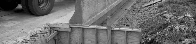
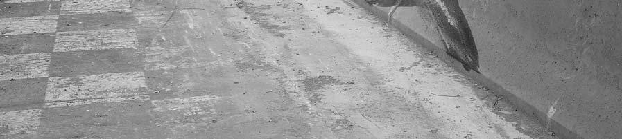
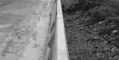
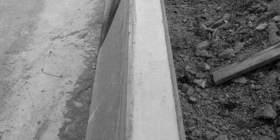
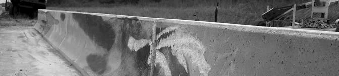
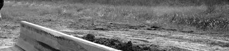
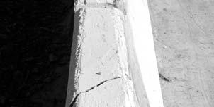
15 CHAPTER 2. STUDY APPROACH TEST FACILITY The test facilities at the Texas Transportation Institute s Proving Ground consist of a 2000-acre (809 hectare) complex of research and training facilities situated 10 mi (16 km) northwest of the main campus of Texas A&M University. The site, formerly an Air Force Base, has large expanses of concrete runways and parking aprons well suited for experimental research and testing in the areas of vehicle performance and handling, vehicle-roadway interaction, durability and efficacy of highway pavements, and safety evaluation of roadside safety hardware. The site selected for placing of the Florida Jersey safety shaped bridge rail is along a wide outof-service apron/runway. The apron/runway consists of an unreinforced jointed-concrete pavement in 12.5 ft by 15 ft (3.8 m by 4.6 m) blocks nominally 8 to 12 inches (203 to 305 mm) deep. The aprons and runways are about 50 years old and the joints have some displacement, but are otherwise flat and level. TEST ARTICLE Design and Construction The Florida Jersey safety shaped barrier selected for testing is depicted in FDOT Sheet Index No. I-799 and more specifically Index Nos and of that sheet. It is a 32-inch (813 mm) tall, 6-inch (152 mm) top, and 15-inch (382 mm) base Jersey safety shaped concrete barrier integrally cast with a 7-inch (178 mm) thick reinforced concrete simulated bridge deck. Longitudinal reinforcement in the bridge parapet is six (6) #4 (#13) bars, three (3) on each face. U shaped #4 (#13) stirrups spaced 8 inches (203 mm) on center are contained entirely in the parapet and extend into the slender portion of the parapet. A shaped #4 (#13) stirrups spaced 8 inches (203 mm) on center hook and align with the U bars and parallel the lower sloped face of the parapet and extend into the lower mat of the bridge deck. L shaped #4 (#13) stirrups at 8 inches (203 mm) on center are placed in the back face of the parapet and extend into the lower mat of the simulated bridge deck. The 7-inch (178 mm) thick bridge deck is laterally reinforced with #5 (#16) bars at 6 inches on center in the top mat and #5 (#16) bars at 12 inches (305 mm) on center in the bottom mat. There were also six (6) #4 (#13) longitudinal bars in the deck. Concrete strengths were 3616 psi (25 MPa) in the parapet and 3931 psi (27 MPa) in the deck. All exposed corners received 3/4 inch (19 mm) chamfer. Additionally, 2-inch (51 mm) expansion joints were cast in the parapets for testing purposes. The deck was continuous. There was no extra reinforcement at expansion joints per the state drawings. Figures 1 and 2 provide more details on the parapet and deck, and Figure 3 presents photographs of the test installation. 3
16 6" 2" 1'-3" 9" 7" " U 8" C.C. 2" COVER (MIN.) (TYP.) " 1'-7" " #4 BARS (TYP.) MIN 30" LAP R10" 2'-8" ALL LONGITUDINAL STEEL IS A #4 BAR CHAMFER ALL EXPOSED CORNERS 3 4" L 8" C.C " 10" " 4" " 1 4" PLATE WELDED TO EXISTING REBAR AND TO NEW HOOK BARS 4 6" O.C. 7" " EXISTING CONCRETE #4 12" C.C " 1' " TO BACK FACE OF BAR 2' " A 8" C.C. 1 2" CONTINUOUS V-GROOVE 3" 12" C.C. BOTTOM SECTION A-A " 8" Figure 1. Cross Section of the Florida Jersey Safety Shaped Bridge Railing.
17 2" CLR (TYP) 75' 24' 2" EXPANSION GAP 2" EXPANSION GAP 24' U 8" C.C. 2" COVER (MIN.) (TYP.) 6" 2" 1'-3" 9" 7" " " 1'-7" " ALL LONGITUDINAL STEEL IS A #4 BAR 3" 6" C.C. #4 12" C.C. 5 #4 BARS (TYP.) MIN 30" LAP R10" 2'-8" CHAMFER ALL EXPOSED CORNERS 3 4" L 8" C.C " 10" 1 4 6" O.C " 7" #4 12" C.C. 1 2" CONTINUOUS V-GROOVE 3" " 1' " TO BACK FACE OF BAR 2' " SECTION A-A 4" " A 8" C.C " " TO NEW HOOK BARS EXISTING CONCRETE 12" C.C. BOTTOM 12" C.C. REBAR LAYOUT IN DECK 8" Figure 2. Details of the Florida Jersey Safety Shaped Bridge Rail.


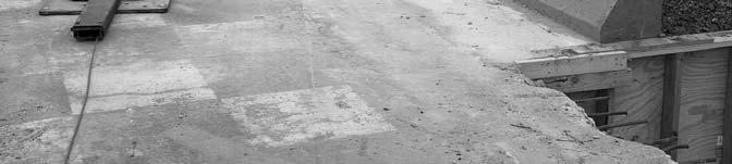
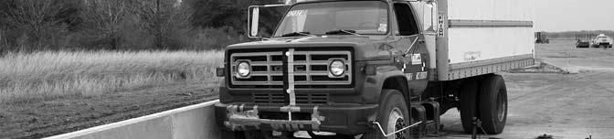
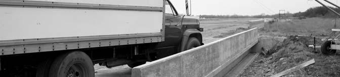
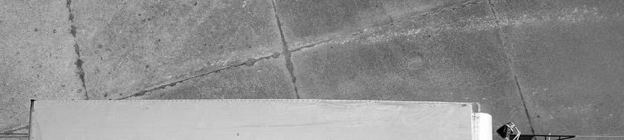
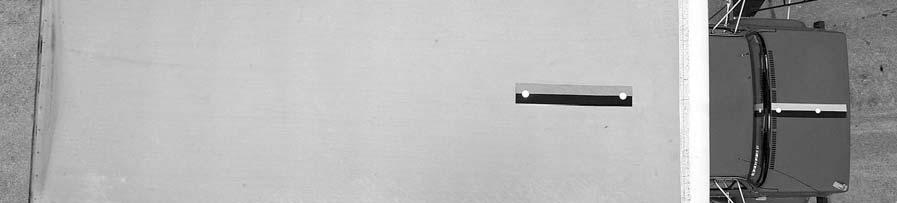
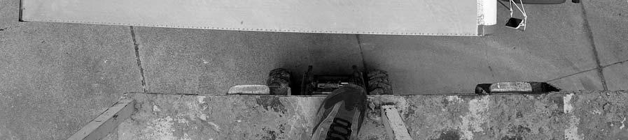
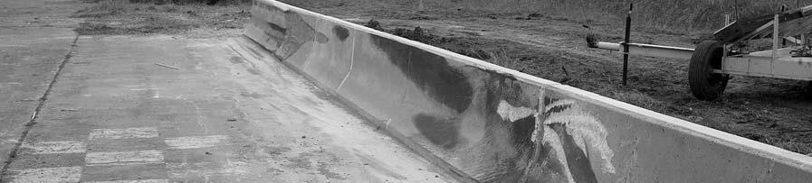
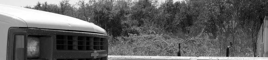
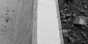
18 Figure 3. Florida Jersey Safety Shaped Bridge Rail before Test
19 Analysis of Bridge Railing The AASHTO LRFD Bridge Specifications Section 13 sets forth test levels and the required test conditions for demonstrating a bridge rail meets a certain test level. The Appendix to Section 13 gives guidelines for designing bridge rails that will perform satisfactorily in fullscale crash tests. The yield line procedure in Section a was used to evaluate the Florida Jersey safety shaped bridge rail. Both the mid-span and end-span conditions were evaluated. Appendix A in this report includes results of the yield line analysis for both conditions. CRASH TEST CONDITIONS Three tests are required to evaluate longitudinal barriers, such as the Florida Jersey safety shaped bridge rail to TL-4 according to NCHRP Report 350 and are described below. NCHRP Report 350 test designation 4-10: An 1806-lb (820 kg) passenger car impacting the bridge rail at the critical impact point (CIP) of the length of need at a nominal speed and angle of 62.2 mi/h (100 km/h) and 20 degrees. The test is intended to evaluate occupant risk and post-impact trajectory. NCHRP Report 350 test designation 4-11: A 4405-lb (2000 kg) pickup truck impacting the bridge rail at the CIP of the length of need at a nominal speed and angle of 62.2 mi/h (100 km/h) and 25 degrees. The test is intended to evaluate strength of the section in containing and redirecting the 4405-lb (2000 kg) vehicle. NCHRP Report 350 test designation 4-12: A 17,621-lb (8000 kg) single-unit truck impacting the bridge rail at the CIP of the length of need at a nominal speed and angle of 49.7 mi/h (80 km/h) and 15 degrees. The test is intended to evaluate strength of the section in containing and redirecting the 17,621-lb (8000 kg) vehicle. Test 4-10 was determined to be non-critical since the Jersey safety shaped barrier has been tested extensively with passenger cars and the focus of this research is structural capacity of this system. The first test reported herein corresponds to NCHRP Report 350 test designation The objective of this particular test was to evaluate the strength of the concrete parapet. According to NCHRP Report 350 guidelines, the target impact point for this test was 4.9 ft (1.5 m) upstream of the joint. The second test performed was NCHRP Report 350 test designation Again, this test was to evaluate the strength of the section in safely containing and redirecting the pickup truck. The target impact point for this test was 3.9 ft (1.2 m) upstream of the joint. The crash tests and data analysis procedures were in accordance with guidelines presented in NCHRP Report 350. Appendix B presents brief descriptions of these procedures. 7
20 EVALUATION CRITERIA The crash tests performed were evaluated in accordance with NCHRP Report 350. As stated in NCHRP Report 350, Safety performance of a highway appurtenance cannot be measured directly but can be judged on the basis of three factors: structural adequacy, occupant risk, and vehicle trajectory after collision. Accordingly, researchers used the safety evaluation criteria from Table 5.1 of NCHRP Report 350 to evaluate the crash tests reported herein. 8
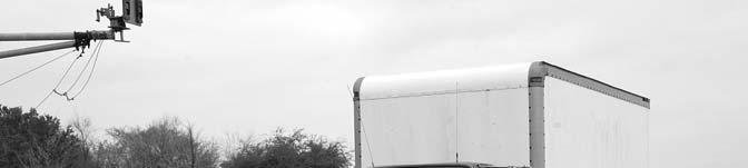
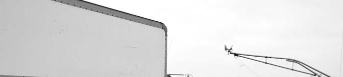
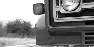
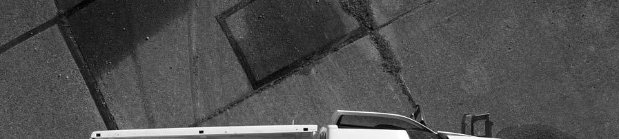
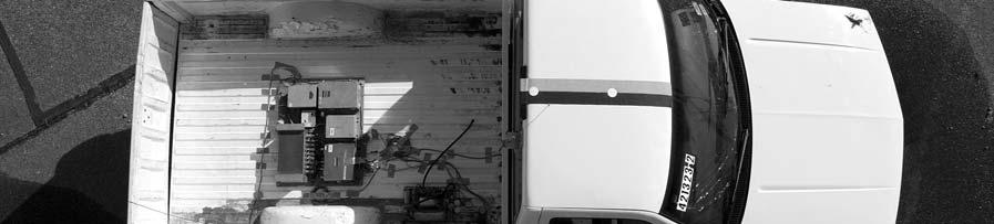
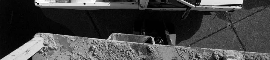
21 CHAPTER 3. CRASH TEST RESULTS TEST NO (NCHRP Report 350 TEST DESIGNATION 4-12) Test Vehicle A 1986 GMC 7000 single-unit truck, shown in Figures 4 and 5, was used for the crash test. Test inertia weight of the vehicle was 17,641 lb (8009 kg), and its gross static weight was 17,641 lb (8009 kg). The height to the lower edge of the vehicle bumper was 20.5 inches (521 mm), and the height to the upper edge of the bumper was 33.5 inches (851 mm). Figure 25 in Appendix C gives additional dimensions and information on the vehicle. The vehicle was directed into the installation using the cable reverse tow and guidance system, and was released to be free-wheeling and unrestrained just prior to impact. Weather Conditions The test was performed on the afternoon of February 18, Weather conditions at the time of testing were as follows: wind speed: 11 mi/h (18 km/h); wind direction: 0 degrees with respect to the vehicle (vehicle was traveling in a southwesterly direction); temperature: 63 ºF (17 ºC); relative humidity: 79 percent. Test Description The single-unit van-truck, traveling at 50.6 mi/h (81.4 km/h), impacted the Florida bridge rail 5.6 ft (1.7 m) upstream of the first joint at an impact angle of 14.3 degrees. Shortly after impact, the right front wheel began to ride up the face of the bridge rail, and at second (s), the truck began to redirect. The right rear tire contacted the bridge rail at s, and the tire blew out at s. At s, the front bumper of the truck reached the top of the bridge rail, and at s, the bumper rode off the end of the bridge rail. The truck lost contact with the bridge rail at s, and was traveling at a speed of 25.7 mi/h (41.4 km/h) and an exit angle of less than 5 degrees toward the bridge rail. Brakes on the truck were applied shortly afterward, and the truck subsequently came to rest ft (32.8 m) downstream of impact. Figures 27 and 28 in Appendix D show sequential photographs of the test period. 9
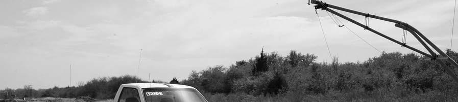
22 Figure 4. Vehicle/Installation Geometrics for Test


23 Figure 5. Vehicle before Test
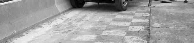
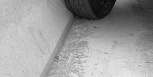
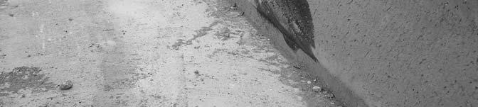
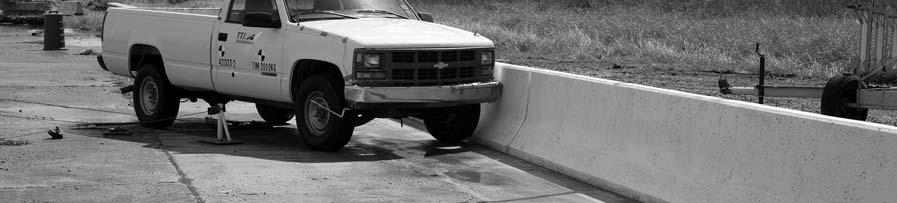
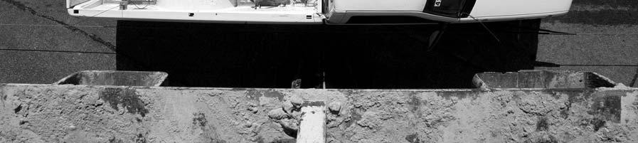
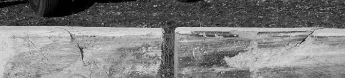
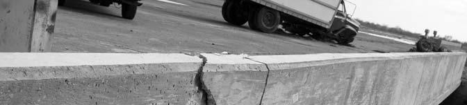
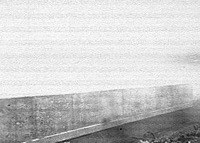
24 Damage to Test Installation Figures 6 and 7 show that the Florida bridge rail sustained cosmetic damage only. A small section on the edge of the first segment of bridge rail was chipped off, measuring 16.5 inches (420 mm) tall by 5.1 inches (130 mm) wide and starting 3.3 inches (85 mm) below the top of the segment. The truck contacted the bridge rail 5.6 ft (1.7 m) upstream of the joint and remained in contact with the bridge rail until it rode off the end. Vehicle Damage Figure 8 shows damage to the vehicle. The front axle was separated from the truck and the right rear wheel rim was bent. The lower right side of the cab and box were deformed. No measurable occupant compartment deformation occurred. Figure 9 shows photographs of the interior of the vehicle. Occupant Risk Factors Data from the accelerometer located at the vehicle center of gravity were digitized for evaluation of occupant risk and were computed as follows. In the longitudinal direction, the occupant impact velocity was 4.9 ft/s (1.5 m/s) at s, the highest s occupant ridedown acceleration was -3.9 gravity or acceleration (g s) from to s, and the maximum s average acceleration was -2.4 g s between and s. In the lateral direction, the occupant impact velocity was 6.6 ft/s (2.0 m/s) at s, the highest s occupant ridedown acceleration was -3.9 g s from to s, and the maximum s average was -4.9 g s between and s. Figure 10 summarizes these data and other pertinent information from the test. Figures 32 through 39 in Appendix E present the vehicle angular displacements and accelerations versus time traces. Assessment of Crash Test Results An assessment of the test based on the applicable NCHRP Report 350 safety evaluation criteria is provided below. Structural Adequacy A. Test article should contain and redirect the vehicle; the vehicle should not penetrate, underride, or override the installation although controlled lateral deflection of the test article is acceptable. Result: The Florida bridge rail contained and redirected the single-unit truck. The truck did not penetrate, underride, or override the installation. Minimal movement of the bridge rail was noted during the test with no permanent deformation. 12

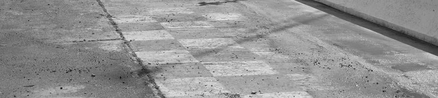
25 Figure 6. After Impact Trajectory Path for Test

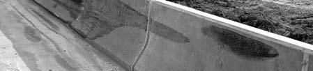
26 Figure 7. Installation after Test


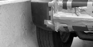
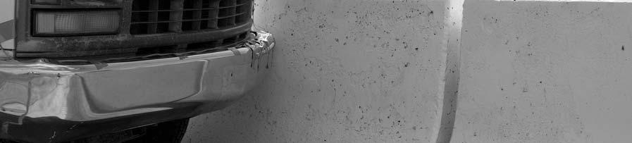
27 Figure 8. Vehicle after Test


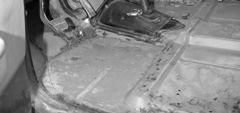
28 Before test After test Figure 9. Interior of Vehicle for Test


29 0.000 s s s s 6" 2" 1'-3" 9" 7" " " 1'-7" " " R10" " 10" 2'-8" ALL LONGITUDINAL STEEL IS A #4 BAR CHAMFER ALL EXPOSED CORNERS 3 4" EXISTING CONCRETE 17 General Information Test Agency... Test No.... Date... Test Article Type... Name... Installation Length... Material or Key Elements... Soil Type and Condition... Test Vehicle Type... Designation... Model... Mass Curb... Test Inertial... Dummy... Gross Static... Texas Transportation Institute Bridge Rail Florida NJ Shaped Bridge Rail 75.0 ft (23 m) 32 in (813 mm) tall Jersey Safety Shaped Bridge Rail Concrete, Dry Production 8000S 1986 GMC Sierra ,180 lb (5076 kg) 17,641 lb (8009 kg) No dummy 17,641 lb (8009 kg) Impact Conditions Speed (mi/h (km/h))... Angle (deg)... Exit Conditions Speed (mi/h (km/h))... Angle (deg)... Occupant Risk Values Impact Velocity (ft/s (m/s)) Longitudinal... Lateral... THIV (km/h)... Ridedown Accelerations (g s) Longitudinal... Lateral... PHD (g s)... ASI... Max s Average (g s) Longitudinal... Lateral... Vertical (81.4) (41.4) ~5 4.9 (1.5) 6.6 (2.0) Test Article Deflections Dynamic... Permanent... Working Width... Vehicle Damage Exterior VDS... CDC... Maximum Exterior Vehicle Crush... Interior OCDI... Maximum Occupant Compartment Deformation... Post-Impact Behavior (during 1.0 sec after impact) Max. Yaw Angel (deg)... Max. Pitch Angle (deg)... Max. Roll Angle (deg) ft (1.8 m) N/A N/A 13.7 in (350 mm) N/A Figure 10. Summary of Results for NCHRP Report 350 Test 4-12 on the Florida Jersey Safety Shaped Bridge Rail.
30 Occupant Risk D. Detached elements, fragments, or other debris from the test article should not penetrate or show potential for penetrating the occupant compartment, or present an undue hazard to other traffic, pedestrians, or personnel in a work zone. Deformation of, or intrusions into, the occupant compartment that could cause serious injuries should not be permitted. Result: No detached elements, fragments, or other debris were present to penetrate or to show potential for penetrating the occupant compartment, or to present undue hazard to others in the area. No measurable deformation of the occupant compartment occurred. G. It is preferable, although not essential, that the vehicle remain upright during and after collision. Result: The single-unit truck remained upright during and after the collision period. Vehicle Trajectory K. After collision, it is preferable that the vehicle s trajectory not intrude into adjacent traffic lanes. Result: The single-unit truck did not intrude into adjacent traffic lanes. M. The exit angle from the test article preferably should be less than 60 percent of the test impact angle, measured at time of vehicle loss of contact with the test device. Result: Exit angle at loss of contact was not attainable, but estimated exit angle was less than 5 degrees toward the bridge rail. The following supplemental evaluation factors and terminology, as presented in the FHWA memo entitled ACTION: Identifying Acceptable Highway Safety Features, were used for visual assessment of test results (4). Criteria underlined below reflect the results for the crash test reported herein. Passenger Compartment Intrusion 1. Windshield Intrusion a. No windshield contact e. Complete intrusion into b. Windshield contact, no damage passenger compartment c. Windshield contact, no intrusion f. Partial intrusion into d. Device embedded in windshield, no passenger compartment significant intrusion 2. Body Panel Intrusion yes or no 18
31 Loss of Vehicle Control 1. Physical loss of control 3. Perceived threat to other vehicles 2. Loss of windshield visibility 4. Debris on pavement Physical Threat to Workers or Other Vehicles 1. Harmful debris that could injure workers or others in the area 2. Harmful debris that could injure occupants in other vehicles No debris was present. Vehicle and Device Condition 1. Vehicle Damage a. None d. Major dents to grill and body panels b. Minor scrapes, scratches or dents e. Major structural damage c. Significant cosmetic dents 2. Windshield Damage a. None e. Shattered, remained intact but b. Minor chip or crack partially dislodged c. Broken, no interference with visibility f. Large portion removed d. Broken or shattered, visibility g. Completely removed restricted but remained intact 3. Device Damage a. None d. Substantial, replacement parts b. Superficial needed for repair c. Substantial, but can be straightened e. Cannot be repaired 19
32 TEST NO (NCHRP Report 350 TEST DESIGNATION 4-11) Test Vehicle Figures 11 and 12 show the 1998 Chevrolet pickup truck used for the crash test. Test inertia weight of the vehicle was 4544 lb (2063 kg), and its gross static weight was 4544 lb (2063 kg). The height to the lower edge of the vehicle bumper was 16.3 inches (415 mm), and the height to the upper edge of the bumper was 25.0 inches (635 mm). Figure 27 in Appendix C gives additional dimensions and information on the vehicle. The vehicle was directed into the installation using the cable reverse tow and guidance system, and was released to be freewheeling and unrestrained just prior to impact. Weather Conditions The test was performed on the afternoon of March 18, Weather conditions at the time of testing were as follows: wind speed: 2 mi/h (3 km/h); wind direction: 200 degrees with respect to the vehicle (vehicle was traveling in a northwesterly direction); temperature: 66 ºF (19 ºC); relative humidity: 62 percent. Test Description The 4544-lb (2063 kg) pickup truck, traveling at a speed of 61.1 mi/h (98.3 km/h), impacted the Florida Jersey safety shaped bridge rail 4.1 ft (1.25 m) upstream of the joint at an impact angle of 26.4 degrees. Shortly after impact, the left front tire began to ride up the face of the bridge rail, and by s after impact, the vehicle began to redirect. The left rear tire of the vehicle contacted the bridge rail at s, and the rear bed of the vehicle contacted the bridge rail at s. At s, the vehicle was traveling parallel with the bridge rail at a speed of 48.1 mi/h (77.4 km/h). The left front tire lost contact with the bridge rail at s. At s, the rear of the vehicle lost contact with the bridge rail and the vehicle was traveling at a speed of 49.8 mi/h (80.1 km/h) and an exit angle of 6.4 degrees. Brakes on the vehicle were applied at approximately 1.5 s after impact, and the vehicle subsequently came to rest 229 ft (69.8 m) downstream of impact and 56 ft (17.2 m) forward of the traffic face of the bridge rail. Figures 30 and 31 in Appendix D display sequential photographs of the collision period. 20

33 Figure 11. Vehicle/Installation Geometrics for Test


34 Figure 12. Vehicle before Test
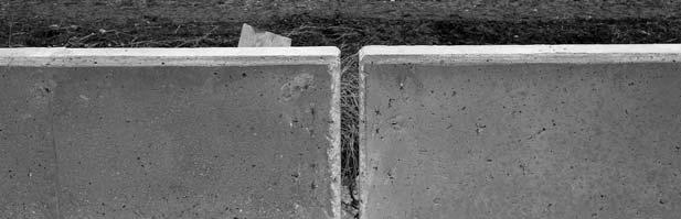
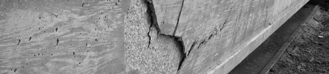
35 Damage to Test Installation Figures 13 and 14 show that the Florida bridge rail sustained moderate structural damage on either side of the joint just upstream of impact. A small section on each of the edges of the first and second segments of bridge rail were cracked, extending a maximum distance of 42.9 inches (1090 mm) upstream on the first segment and a maximum distance of 33.7 inches (855 mm) downstream on the second segment. A hairline crack in the deck radiated downward from the field side corner of the downstream segment and extended 6.0 inches (152 mm) under the deck. Maximum dynamic deflection was not attainable, and maximum permanent deformation was 0.75 inches (19 mm). The truck contacted the bridge rail 4.1 ft (1.25 m) upstream of the joint and remained in contact with the bridge rail for a distance of 17.2 ft (5.23 m). Vehicle Damage Figure 15 shows the damage to the vehicle. Structural damage was imparted to the left outer tie rod end, lower A-arm and spindle, front of the frame rail, and the firewall and floor pan. The inner rim of the left wheel separated from the outer rim. Also damaged were the front bumper, grill, radiator, left front quarter panel, left door, left rear exterior bed, left rear tire, and the right rear of the bed. The windshield also sustained stress cracks and the door glass was broken out. Maximum exterior crush to the pickup was 25.2 inches (640 mm) in the side plane at the left front corner just above bumper height. Maximum occupant compartment deformation was 3.4 inches (87 mm) in the left side firewall area. Figure 16 shows photographs of the interior of the vehicle. Tables 3 and 4 in Appendix C show exterior crush profile and occupant compartment deformation. Occupant Risk Factors Data from the triaxial accelerometer, located at the vehicle center of gravity, were digitized to compute occupant impact velocity and ridedown accelerations. Only the occupant impact velocity and ridedown accelerations in the longitudinal axis are required from these data for evaluation of criterion L in NCHRP Report 350. In the longitudinal direction, occupant impact velocity was 19.4 ft/s (5.9 m/s) at s, maximum s ridedown acceleration was g s from to s, and the maximum s average was -9.0 g s between and s. In the lateral direction, the occupant impact velocity was 9.1 m/s at s, the highest s occupant ridedown acceleration was 5.5 g s from to s, and the maximum s average was 15.3 g s between and s. Figure 17 presents these data and other information pertinent to the test. Figures 40 through 46 in Appendix E show vehicle angular displacements and accelerations versus time traces. 23


36 Figure 13. After Impact Trajectory Path for Test
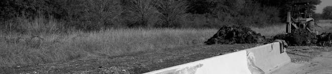
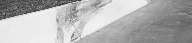
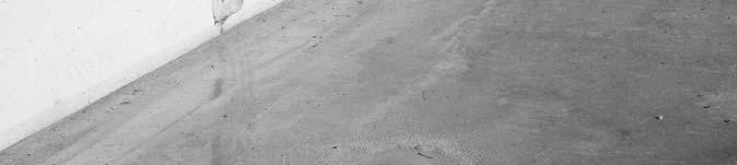
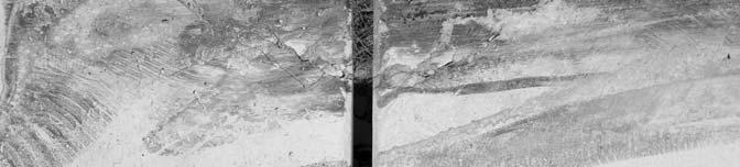

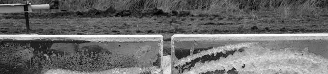
37 Figure 14. Installation after Test


38 Figure 15. Vehicle after Test


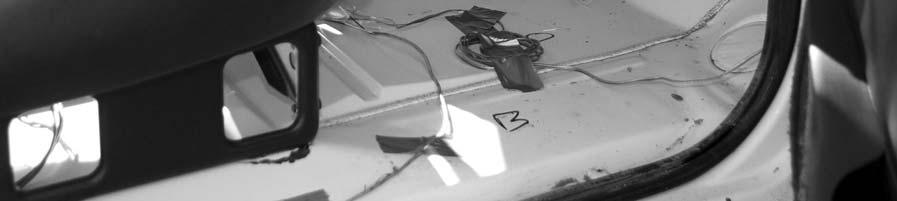
39 Before Test After test Figure 16. Interior of Vehicle for Test

40 0.000 s s s s 6" 2" 1'-3" 9" 7" " " 1'-7" " " R10" " 10" 2'-8" ALL LONGITUDINAL STEEL IS A #4 BAR CHAMFER ALL EXPOSED CORNERS 3 4" EXISTING CONCRETE 28 General Information Test Agency... Test No.... Date... Test Article Type... Name... Installation Length... Material or Key Elements... Soil Type and Condition... Test Vehicle Type... Designation... Model... Mass Curb... Test Inertial... Dummy... Gross Static... Texas Transportation Institute Bridge Rail Florida NJ Shaped Bridge Rail 75.0 ft (23 m) 32 in (813 mm) tall Jersey Safety Shaped Bridge Rail Concrete, Dry Production 2000P 1998 Chevrolet lb (2174 kg) 4544 lb (2063 kg) N/A 4544 lb (2063 kg) Impact Conditions Speed (mi/h (km/h))... Angle (deg)... Exit Conditions Speed (mi/h (km/h))... Angle (deg)... Occupant Risk Values Impact Velocity (ft/s (m/s)) Longitudinal... Lateral... THIV (km/h)... Ridedown Accelerations (g s) Longitudinal... Lateral... PHD (g s)... ASI... Max s Average (g s) Longitudinal... Lateral... Vertical (98.3) (80.1) (5.9) 29.9 (9.1) Test Article Deflections Dynamic... N/A Permanent in (19 mm) Working Width in (723 mm) Vehicle Damage Exterior VDS... 11LFQ4 CDC... 11FYEW4 Maximum Exterior Vehicle Crush... Interior OCDI... Maximum Occupant Compartment Deformation... Post-Impact Behavior (during 1.0 sec after impact) Max. Yaw Angel (deg) Max. Pitch Angle (deg) Max. Roll Angle (deg) in (640 mm) FS in (87 mm) Figure 17. Summary of Results for NCHRP Report 350 Test 4-11 on the Florida Jersey Safety Shaped Bridge Rail.
41 Assessment of Crash Test Results An assessment of the test based on the applicable NCHRP Report 350 safety evaluation criteria is provided below. Structural Adequacy A. Test article should contain and redirect the vehicle; the vehicle should not penetrate, underride, or override the installation although controlled lateral deflection of the test article is acceptable. Result: The Florida bridge rail contained and redirected the pickup truck. The truck did not penetrate, underride, or override the installation. Minimal movement of the bridge rail was noted during the test with maximum permanent deformation of 0.75 inches (19 mm). Occupant Risk D. Detached elements, fragments, or other debris from the test article should not penetrate or show potential for penetrating the occupant compartment, or present an undue hazard to other traffic, pedestrians, or personnel in a work zone. Deformation of, or intrusions into, the occupant compartment that could cause serious injuries should not be permitted. Result: No detached elements, fragments, or other debris were present to penetrate or to show potential for penetrating the occupant compartment, or to present undue hazard to others in the area. Maximum deformation of the occupant compartment was 3.4 inches (87 mm) in the left side firewall area. F. The vehicle should remain upright during and after collision although moderate roll, pitching, and yawing are acceptable. Result: The pickup truck remained upright during and after the collision period. Vehicle Trajectory K. After collision, it is preferable that the vehicle s trajectory not intrude into adjacent traffic lanes. Result: The pickup truck came to rest 229 ft (69.8 m) downstream of impact and 56 ft (17.2 m) forward of the traffic face of the bridge rail. L. The occupant impact velocity in the longitudinal direction should not exceed 12 m/sec and the occupant ridedown acceleration in the longitudinal direction should not exceed 20 g s. 29
42 Result: The longitudinal occupant impact velocity was 19.4 ft/s (5.9 m/s) and the longitudinal ridedown acceleration was g s. M. The exit angle from the test article preferably should be less than 60 percent of the test impact angle, measured at time of vehicle loss of contact with the test device. Result: Exit angle at loss of contact was 6.4 degrees, which was 24 percent of the impact angle. The following supplemental evaluation factors and terminology, as presented in the FHWA memo entitled ACTION: Identifying Acceptable Highway Safety Features, were used for visual assessment of test results (4). Criteria underlined below pertain to the results of the crash test reported herein. Passenger Compartment Intrusion 1. Windshield Intrusion a. No windshield contact e. Complete intrusion into b. Windshield contact, no damage passenger compartment c. Windshield contact, no intrusion f. Partial intrusion into d. Device embedded in windshield, no passenger compartment significant intrusion 2. Body Panel Intrusion yes or no Loss of Vehicle Control 1. Physical loss of control 3. Perceived threat to other vehicles 2. Loss of windshield visibility 4. Debris on pavement Physical Threat to Workers or Other Vehicles 1. Harmful debris that could injure workers or others in the area 2. Harmful debris that could injure occupants in other vehicles No debris was present. Vehicle and Device Condition 1. Vehicle Damage a. None d. Major dents to grill and body panels b. Minor scrapes, scratches or dents e. Major structural damage c. Significant cosmetic dents 2. Windshield Damage a. None e. Shattered, remained intact but b. Minor chip or crack (stress) partially dislodged c. Broken, no interference with visibility f. Large portion removed d. Broken or shattered, visibility g. Completely removed restricted but remained intact 30
43 3. Device Damage a. None d. Substantial, replacement parts b. Superficial needed for repair c. Substantial, but can be straightened e. Cannot be repaired 31
44


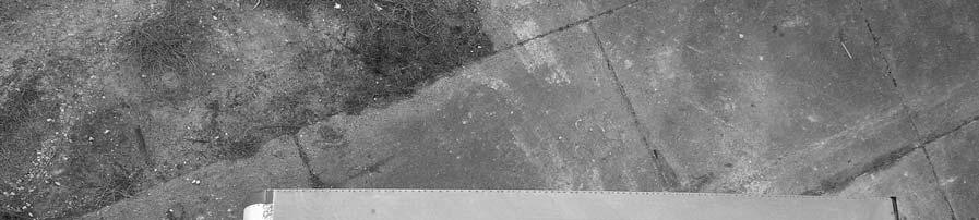
45 CHAPTER 4. STATIC LOAD TESTS STATIC LOAD TESTS ON SAFETY SHAPED TEST INSTALLATION The AASHTO LRFD design method analysis indicated the potential for poor performance in the full-scale crash test. Static tests replicating the loads used in the design procedure in LRFD were performed to verify actual capacities of the bridge parapet. The static load tests were performed with a hydraulic ram attached to a braced load frame, pushing on a load cell, and placed against a spreader beam, W12 50 (W310 74), 42 inches (1067 mm) long. A thin sloped piece of timber was placed on the face of the spreader beam to create a vertical pushing face for the load cell and ram. It also minimized stress concentrations due to surface imperfections in the parapet. Figure 18 shows the test setup. Figure 18. Test Setup for Static Load Testing. 33
.")
 from the end of the")
 80000 70000 60000 50000 40000 30000 20000 10000 0 0.0 0.5 1.")
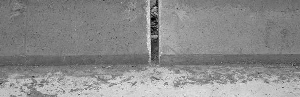
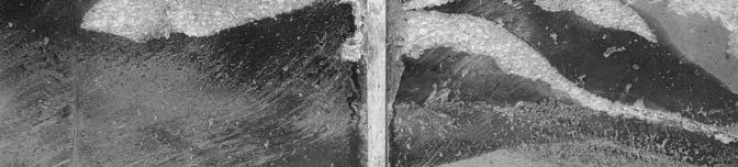
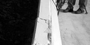
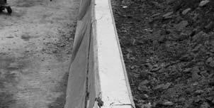
46 Test S-1 Test S-1 was on the upstream end of the test installation and was intended to represent the loading at a construction joint. The maximum load attained was 35.1 kips (156 kn). The anticipated load from the yield line analysis was 41.5 kips (185 kn). Subsequent review of the installation showed the last stirrup was approximately 6 inches (152 mm) from the end of the parapet wall and likely contributed to the lower fracture load. Figure 19 shows the results of the static test S-1. Figure 20 shows the failure mode. Test S1 Force (lb) Displacement (in) Figure 19. Results of Test S1. Figure 20. Failure Mode for Test S1. 34


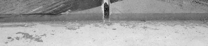
47 Test S-2 Visual inspection of the bridge parapet after the TL-4 test did not reveal any perceptible cracking. Since the test setup was readily available, the impact region of the barrier was statically tested to failure at the expansion joint. The maximum load was 45.1 kips (201 kn) and the test results are shown in Figure 21 below. Figure 22 shows the failure mode. Test S2 Force (lb) Displacement (in) Figure 21. Results for Test S2. Figure 22. Failure Mode for Test S2. 35
. The maximum load obtained was 73.")

 80000 70000 60000 50000 40000 30000 20000 10000 0 0.0 0.5 1.")
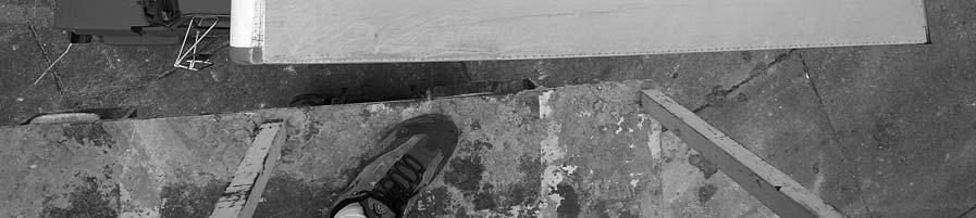
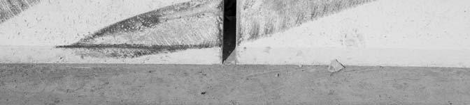
48 Test S-3 Test S-3 was at mid-span of the undamaged rail section as shown in Figure 23. The predicted failure load was 62.1 kips (276 kn). The maximum load obtained was 73.1 kips (325 kn). Figure 24 shows test results. Yield lines were confined to the upper, slender portion of the parapet as shown in Figure 25. Figure 23. Setup for Test S3. Test S3 Force (lb) Displacement (in) Figure 24. Results of Test S3. 36


49 Figure 25. Failure Mode for Test S3. 37
50
51 CHAPTER 5. SUMMARY AND CONCLUSIONS SUMMARY OF CRASH TEST RESULTS NCHRP Report 350 Test Designation 4-12 The Florida bridge rail contained and redirected the single-unit truck. The truck did not penetrate, underride, or override the installation. Minimal movement of the bridge rail was noted during the test with no permanent deformation. No detached elements, fragments, or other debris were present to penetrate or to show potential for penetrating the occupant compartment, or to present undue hazard to others in the area. No measurable deformation of the occupant compartment occurred. The single-unit truck remained upright during and after the collision period. The single-unit truck did not intrude into adjacent traffic lanes. Exit angle at loss of contact was not attainable, but estimated exit angle was less than 5 degrees with trajectory heading referenced toward the bridge rail. NCHRP Report 350 Test Designation 4-11 The Florida bridge rail contained and redirected the 4405-lb (2000 kg) pickup truck. The truck did not penetrate, underride, or override the installation. Minimal movement of the bridge rail was noted during the test with maximum permanent deformation of 0.75 inches (19 mm). No detached elements, fragments, or other debris were present to penetrate or to show potential for penetrating the occupant compartment, or to present undue hazard to others in the area. Maximum deformation of the occupant compartment was 3.4 inches (87 mm) in the left side firewall area. The pickup truck remained upright during and after the collision period. The pickup truck came to rest 229 ft (69.8 m) downstream of impact and 56 ft (17.2 m) forward of the traffic face of the bridge rail. The longitudinal occupant impact velocity was 19.4 ft/s (5.9 m/s) and the longitudinal ridedown acceleration was g s. Exit angle at loss of contact was 6.4 degrees, which was 24 percent of the impact angle. SUMMARY OF STATIC TEST RESULTS With successful redirection of both the single unit truck and the pickup, the parapet was deemed acceptable and remaining tasks of the project for further analysis and possible retrofits became unnecessary. Since the AASHTO LRFD design method had indicated the potential for poor performance in the full-scale crash test, static tests replicating the loads used in the design procedure in LRFD were performed to verify actual capacities of the bridge parapet. The only undamaged portions of the parapet were at mid-spans and the outside ends of the parapets. The end of the installation opposite from the crash test impact was selected for the static load test at a joint and the actual load at breakage of the parapet at the expansion joint was 35.1 kips (156 kn) while the predicted load was 41.1 kips (183 kn). Since the actual load did not achieve the anticipated design load, the damaged concrete was removed and the end stirrup was found to be approximately 6 inches (152 mm) from the end of the parapet. This location was not originally 39
52 intended for impact or static testing so the inspection prior to concrete placement did not reveal the deficiency. The damage from the single-unit truck impact at an expansion joint appeared to be limited to surface scarring of the concrete no visible cracks were identified. A static test at this location would serve two purposes: 1) it would verify that visual inspections may be acceptable for determining structural integrity after an impact and 2) stirrup placement was verified before concrete placement and actual load should more closely match the predicted design load. The ultimate static load at this location was 45.1 kips (201 kn), predicted was again 41.1 kips (183 kn). Therefore the actual load exceeded the yield line analysis prediction by approximately 10 percent. CONCLUSIONS The Florida bridge rail performed acceptably according to the specifications of NCHRP Report 350 test designations 4-12 and 4-11, as shown in Tables 1 and 2. In test 4-12 with the single-unit van-truck, the parapet received cosmetic damage only. The subsequent static load test at the impact location failed the parapet at 45.1 kips (201 kn). The AASHTO LRFD Bridge Design Specifications uses a 54-kip (240 kn) design load for single-unit trucks. Since the parapet was not structurally damaged in the TL-4 test with the single-unit truck, further research should be undertaken to account for the reduced loads apparently imparted by the impacting single-unit truck. IMPLEMENTATION STATEMENT No field retrofits or replacements of the Florida Jersey safety shaped bridge rails, depicted in the Florida DOT Index 799, are warranted since the most critical 32-inch (813 mm) Jersey safety shaped railing complied with the requirements of the AASHTO LRFD Bridge Design Specifications and NCHRP Report 350 Test Level 4. 40
53 Table 1. Performance Evaluation Summary for NCHRP Report 350 Test 4-12 on the Florida Jersey Safety Shaped Bridge Rail. 41 Test Agency: Texas Transportation Institute Test No.: Test Date: 02/18/2003 NCHRP Report 350 Test 4-12 Evaluation Criteria Test Results Assessment Structural Adequacy A. Test article should contain and redirect the vehicle; the vehicle should not penetrate, underride, or override the installation although controlled lateral deflection of the test article is acceptable. Occupant Risk D. Detached elements, fragments or other debris from the test article should not penetrate or show potential for penetrating the occupant compartment, or present an undue hazard to other traffic, pedestrians, or personnel in a work zone. Deformations of, or intrusions into, the occupant compartment that could cause serious injuries should not be permitted. G. It is preferable, although not essential, that the vehicle remain upright during and after collision. Vehicle Trajectory K. After collision it is preferable that the vehicle s trajectory not intrude into adjacent traffic lanes. M. The exit angle from the test article preferably should be less than 60 percent of test impact angle, measured at time of vehicle loss of contact with test device. *Criteria K and M are preferable, not required. The Florida bridge rail contained and redirected the single-unit truck. The truck did not penetrate, underride, or override the installation. Minimal movement of the bridge rail was noted during the test, and there was no measurable permanent deformation. No detached elements, fragments, or other debris were present to penetrate or to show potential for penetrating the occupant compartment, or to present undue hazard to others in the area. No measurable deformation of the occupant compartment occurred. The single-unit truck remained upright during and after the collision period. The vehicle did not intrude into adjacent traffic lanes. Exit angle at loss of contact was not attainable, but was estimated to be less than 5 degrees toward the bridge rail. Pass Pass Pass Pass Pass
54 Table 2. Performance Evaluation Summary for NCHRP Report 350 Test 4-11 on the Florida Jersey Safety Shaped Bridge Rail. 42 Test Agency: Texas Transportation Institute Test No.: Test Date: 03/18/2003 NCHRP Report 350 Test 4-11 Evaluation Criteria Test Results Assessment Structural Adequacy A. Test article should contain and redirect the vehicle; the vehicle should not penetrate, underride, or override the installation although controlled lateral deflection of the test article is acceptable. Occupant Risk D. Detached elements, fragments or other debris from the test article should not penetrate or show potential for penetrating the occupant compartment, or present an undue hazard to other traffic, pedestrians, or personnel in a work zone. Deformations of, or intrusions into, the occupant compartment that could cause serious injuries should not be permitted. F. The vehicle should remain upright during and after collision although moderate roll, pitching, and yawing are acceptable. Vehicle Trajectory K. After collision it is preferable that the vehicle s trajectory not intrude into adjacent traffic lanes. L. The occupant impact velocity in the longitudinal direction should not exceed 12 m/sec and the occupant ridedown acceleration in the longitudinal direction should not exceed 20 g s. M. The exit angle from the test article preferably should be less than 60 percent of test impact angle, measured at time of vehicle loss of contact with test device. *Criteria K and M are preferable, not required. The Florida bridge rail contained and redirected the pickup truck. The truck did not penetrate, underride, or override the installation. Maximum permanent deformation of the bridge rail was 0.75 inches (19 mm). No detached elements, fragments, or other debris were present to penetrate or to show potential for penetrating the occupant compartment, or to present undue hazard to others in the area. Maximum deformation of the occupant compartment was 3.4 inches (87 mm) in the left side firewall area. The pickup truck remained upright during and after the collision period. The pickup truck came to rest 229 ft (69.8 m) downstream of impact and 56 ft (17.2 m) forward of the traffic face of the bridge rail. The longitudinal occupant impact velocity was 19.4 ft/s (5.9 m/s) and the longitudinal ridedown acceleration was g s. Exit angle at loss of contact was 6.4 degrees, which was 24 percent of the impact angle. Pass Pass Pass Fail Pass Pass
55 REFERENCES 1. American Association of State Highway and Transportation Officials. LRFD Bridge Design Specifications, AASHTO Subcommittee on Bridges and Structures, Washington, D.C., May K. K. Mak and W. L. Campise. Test and Evaluation of Ontario Tall Wall Barrier with an 80,000-Pound Tractor-Trailer, Texas Transportation Institute, Contract No for Ontario Ministry of Transportation, College Station, Texas, H. E. Ross, Jr., D. L. Sicking, R. A. Zimmer and J. D. Michie. Recommended Procedures for the Safety Performance Evaluation of Highway Features, National Cooperative Highway Research Program Report 350, Transportation Research Board, National Research Council, Washington, D.C., Federal Highway Administration Memorandum from the Director, Office of Engineering, entitled: ACTION: Identifying Acceptable Highway Safety Features, dated July 25,
56
57 APPENDIX A. YIELD LINE ANALYSIS OF FDOT BRIDGE RAILS 45
58 46
59 47
60 48
61 49
62 50
63 51
64 52
65 53
66 54
67 55
68 56
69 APPENDIX B. CRASH TEST PROCEDURES AND DATA ANALYSIS The crash tests and data analysis procedures were in accordance with guidelines presented in NCHRP Report 350. Brief descriptions of these procedures are presented as follows. ELECTRONIC INSTRUMENTATION AND DATA PROCESSING The test vehicle was instrumented with three solid-state angular rate transducers to measure roll, pitch, and yaw rates; a triaxial accelerometer near the vehicle center of gravity (c.g.) to measure longitudinal, lateral, and vertical acceleration levels; and a backup biaxial accelerometer in the rear of the vehicle to measure longitudinal and lateral acceleration levels. These accelerometers were Endevco Model 2262CA, piezoresistive accelerometers with a +100 g range. The accelerometers are strain gage type with a linear millivolt output proportional to acceleration. Angular rate transducers are solid state, gas flow units designed for high- g service. Signal conditioners and amplifiers in the test vehicle increase the low-level signals to a +2.5 volt maximum level. The signal conditioners also provide the capability of an R-cal (resistive cal) or shunt calibration for the accelerometers and a precision voltage calibration for the rate transducers. The electronic signals from the accelerometers and rate transducers are transmitted to a base station by means of a 15-channel, constant bandwidth, Inter-Range Instrumentation Group (IRIG), FM/FM telemetry link for recording on magnetic tape and for display on a real-time strip chart. Calibration signals, from the test vehicle, are recorded before the test and immediately afterwards. A crystal-controlled time reference signal is simultaneously recorded with the data. Wooden dowels actuate pressure-sensitive switches on the bumper of the impacting vehicle prior to impact by wooden dowels to indicate the elapsed time over a known distance to provide a measurement of impact velocity. The initial contact also produces an event mark on the data record to establish the instant of contact with the installation. The multiplex of data channels, transmitted on one radio frequency, is received and demultiplexed onto separate tracks of a 28-track, IRIG tape recorder. After the test, the data are played back from the tape machine and digitized. A proprietary software program (WinDigit) converts the analog data from each transducer into engineering units using the R-cal and pre-zero values at 10,000 samples per second per channel. WinDigit also provides Society of Automotive Engineers (SAE) J211 class 180 phaseless digital filtering and vehicle impact velocity. All accelerometers are calibrated annually according to SAE J by means of an Endevco 2901, precision primary vibration standard. This device and its support instruments are returned to the factory annually for a National Institute of Standards Technology (NIST) traceable calibration. The subsystems of each data channel are also evaluated annually, using instruments with current NIST traceability, and the results are factored into the accuracy of the total data channel, per SAE J211. Calibrations and evaluations are made any time data is suspect. 57
70 The Test Risk Assessment Program (TRAP) uses the data from WinDigit to compute occupant/compartment impact velocities, time of occupant/compartment impact after vehicle impact, and the highest 10-millisecond (ms) average ridedown acceleration. WinDigit calculates change in vehicle velocity at the end of a given impulse period. In addition, WinDigit computes maximum average accelerations over 50-ms intervals in each of the three directions. For reporting purposes, the data from the vehicle-mounted accelerometers are filtered with a 60-Hz digital filter, and acceleration versus time curves for the longitudinal, lateral, and vertical directions are plotted using TRAP. TRAP uses the data from the yaw, pitch, and roll rate transducers to compute angular displacement in degrees at s intervals and then plots yaw, pitch, and roll versus time. These displacements are in reference to the vehicle-fixed coordinate system with the initial position and orientation of the vehicle-fixed coordinate systems being initial impact. ANTHROPOMORPHIC DUMMY INSTRUMENTATION Use of a dummy in the 4405-lb (2000 kg) and 17, 621-lb (8000 kg) vehicles is optional according to NCHRP Report 350, and there was no dummy used in the tests with the 2000P vehicle. PHOTOGRAPHIC INSTRUMENTATION AND DATA PROCESSING Photographic coverage of the test included three high-speed cameras: one overhead with a field of view perpendicular to the ground and directly over the impact point; one placed behind the installation at an angle; and a third placed to have a field-of-view parallel to and aligned with the installation at the downstream end. A flash bulb activated by pressure-sensitive tape switches was positioned on the impacting vehicle to indicate the instant of contact with the installation and was visible from each camera. The films from these high-speed cameras were analyzed on a computer-linked Motion Analyzer to observe phenomena occurring during the collision and to obtain time-event, displacement, and angular data. A 16-mm movie cine, a BetaCam, a VHS-format video camera and recorder, and still cameras were used to record and document conditions of the test vehicle and installation before and after the test. TEST VEHICLE PROPULSION AND GUIDANCE The test vehicle was towed into the test installation using a steel cable guidance and reverse tow system. A steel cable for guiding the test vehicle was tensioned along the path, anchored at each end, and threaded through an attachment to the front wheel of the test vehicle. An additional steel cable was connected to the test vehicle, passed around a pulley near the impact point, through a pulley on the tow vehicle, and then anchored to the ground such that the tow vehicle moved away from the test site. A 2-to-1 speed ratio between the test and tow vehicle existed with this system. Just prior to impact with the installation, the test vehicle was released to be free-wheeling and unrestrained. The vehicle remained free-wheeling, i.e., no steering or 58
71 braking inputs, until the vehicle cleared the immediate area of the test site, at which time the vehicle s brakes were activated to bring it to a safe and controlled stop. 59
72
73 APPENDIX C. TEST VEHICLE PROPERTIES AND INFORMATION Date: Test No.: VIN No. 1GDG7D1B86V Year: 1986 Make: GMC Model: 7000 Sierra Tire Inflation Pressure: Odometer: Tire Size: 11 R 22.5 Describe any damage to the vehicle prior to test: Denotes accelerometer location. NOTES: Accelerometer Locations (mm): x y z f rt 1145 c N/A N/A N/A r Geometry (mm) A 2438 E 2515 J 1588 N 133 R 1016 B 813 F 8128 K 762 O 521 S 591 C 4801 G L 1232 P 2007 D 3442 H M 851 Q 1829 Mass (kg) Curb Test Inertial Gross Static M M M Total Mass Distribution (kg): LF: 1435 RF: 1103 LR: 2667 RR: 2803 Figure 26. Vehicle Properties for Test
74 Date: Test No.: VIN No. 1GCGC24R9W Year: 1998 Make: Chevrolet Model: Cheyenne 2500 Tire Inflation Pressure: 50/80psi Odometer: Tire Size: 245/75 R 16 Describe any damage to the vehicle prior to test: #505 Denotes accelerometer location. NOTES: Engine Type: V8 Engine CID: 5.7 Liter Transmission Type: x Auto Manual Optional Equipment: 8-lug Dummy Data: Type: Mass: Seat Position: None N/A N/A Geometry (mm) A 1880 E 1310 J 1038 N 1590 R 750 B 810 F 5470 K 635 O 1610 S 900 C 3350 G L 70 P 725 T 1460 D 1820 H M 415 Q 440 U 3360 Mass (kg) Curb Test Inertial Gross Static M M M Total Mass Distribution (kg): LF: 594 RF: 594 LR: 431 RR: 444 Figure 27. Vehicle Properties for Test
75 Table 3. Exterior Crush Measurements for Test VEHICLE CRUSH MEASUREMENT SHEET 1 Complete When Applicable End Damage Side Damage Undeformed end width Bowing: B1 X1 Corner shift: A1 End shift at frame (CDC) (check one) A2 < 4 inches > 4 inches Bowing constant X 1+ X 2 2 B2 X2 = Note: Measure C 1 to C 6 from Driver to Passenger side in Front or Rear impacts Rear to Front in Side Impacts. All measurements in mm. Specific Impact Number Plane* of C-Measurements Direct Damage Width** (CDC) Max*** Crush Field L** C 1 C 2 C 3 C 4 C 5 C 6 ±D 1 At Front Bumper mm Above Ground N/A N/A Table taken from National Accident Sampling System (NASS). *Identify the plane at which the C-measurements are taken (e.g., at bumper, above bumper, at sill, above sill, at beltline, etc.) or label adjustments (e.g., free space). Free space value is defined as the distance between the baseline and the original body contour taken at the individual C locations. This may include the following: bumper lead, bumper taper, side protrusion, side taper, etc. Record the value for each C-measurement and maximum crush. **Measure and document on the vehicle diagram the beginning or end of the direct damage width and field L (e.g., side damage with respect to undamaged axle). ***Measure and document on the vehicle diagram the location of the maximum crush. Note: Use as many lines/columns as necessary to describe each damage profile. 63
76 Table 4. Occupant Compartment Measurements for Test T R U C K Occupant Compartment Deformation BEFORE (mm) AFTER (mm) A A A B B B C C2 N/A N/A C D D D E E F G H I *Lateral area across the cab from driver s side kickpanel to passenger s side kickpanel. J*


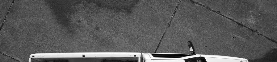
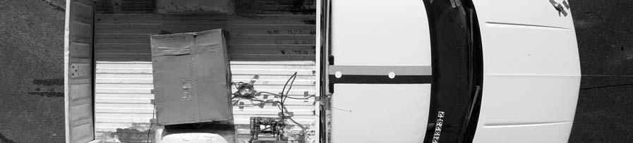
77 APPENDIX D. SEQUENTIAL PHOTOGRAPHS s s s s Figure 28. Sequential Photographs for Test (Overhead and Frontal Views). 65


")
78 0.728 s s s s Figure 28. Sequential Photographs for Test (Overhead and Frontal views) (continued). 66


79 0.000 s s s s s s s s Figure 29. Sequential Photographs for Test (Rear View). 67


80 0.000 s s s s Figure 30. Sequential Photographs for Test (Overhead and Frontal Views). 68


")
81 0.487 s s s s Figure 30. Sequential Photographs for Test (Overhead and Frontal Views) (continued). 69


82 0.000 s s s s s s s s Figure 31. Sequential Photographs for Test (Rear View). 70
Texas Transportation Institute The Texas A&M University System College Station, Texas
 1. Report No. FHWA/TX-05/9-8132-P7 4. Title and Subtitle TL-4 CRASH TESTING OF THE F411 BRIDGE RAIL 2. Government Accession No. 3. Recipient's Catalog No. 5. Report Date October 2004 Technical Report Documentation
Form DOT F (8-72) Texas Transportation Institute The Texas A&M University System College Station, Texas
 Texas Transportation Institute The Texas A&M University System College Station, Texas") 1. Report No. FHWA/TX-02/4162-1 Technical Report Documentation Page 2. Government Accession No. 3. Recipient's Catalog No. 4. Title and Subtitle EVALUATION OF TEXAS GRID-SLOT PORTABLE CONCRETE BARRIER
1. Report No. FHWA/TX-02/4162-1 Technical Report Documentation Page 2. Government Accession No. 3. Recipient's Catalog No. 4. Title and Subtitle EVALUATION OF TEXAS GRID-SLOT PORTABLE CONCRETE BARRIER
NCHRP Report 350 Crash Testing and Evaluation of the S-Square Mailbox System
 TTI: 0-5210 NCHRP Report 350 Crash Testing and Evaluation of the S-Square Mailbox System ISO 17025 Laboratory Testing Certificate # 2821.01 Crash testing performed at: TTI Proving Ground 3100 SH 47, Building
A MASH Compliant W-Beam Median Guardrail System
 0 0 0 0 0 A MASH Compliant W-Beam Median Guardrail System By A. Y. Abu-Odeh, R. P. Bligh, W. Odell, A. Meza, and W. L. Menges Submitted: July 0, 0 Word Count:, + ( figures + tables=,000) =, words Authors:
Texas Transportation Institute The Texas A&M University System College Station, Texas
 1. Report No. FHWA/TX-07/0-5527-1 4. Title and Subtitle DEVELOPMENT OF A LOW-PROFILE TO F-SHAPE TRANSITION BARRIER SEGMENT 2. Government Accession No. 3. Recipient's Catalog No. Technical Report Documentation
GUARDRAIL TESTING MODIFIED ECCENTRIC LOADER TERMINAL (MELT) AT NCHRP 350 TL-2. Dean C. Alberson, Wanda L. Menges, and Rebecca R.
 AT NCHRP 350 TL-2. Dean C. Alberson, Wanda L. Menges, and Rebecca R.") GUARDRAIL TESTING MODIFIED ECCENTRIC LOADER TERMINAL (MELT) AT NCHRP 350 TL-2 Dean C. Alberson, Wanda L. Menges, and Rebecca R. Haug Prepared for The New England Transportation Consortium July 2002 NETCR
GUARDRAIL TESTING MODIFIED ECCENTRIC LOADER TERMINAL (MELT) AT NCHRP 350 TL-2 Dean C. Alberson, Wanda L. Menges, and Rebecca R. Haug Prepared for The New England Transportation Consortium July 2002 NETCR
Texas Transportation Institute The Texas A&M University System College Station, Texas
 2. Government Accession No. 3. Recipient's Catalog No. 1. Report No. FHWA/TX-03/0-4138-3 4. Title and Subtitle PERFORMANCE OF THE TXDOT T202 (MOD) BRIDGE RAIL REINFORCED WITH FIBER REINFORCED POLYMER BARS
CRASH TEST AND EVALUATION OF 3-FT MOUNTING HEIGHT SIGN SUPPORT SYSTEM
 TTI: 9-1002-15 CRASH TEST AND EVALUATION OF 3-FT MOUNTING HEIGHT SIGN SUPPORT SYSTEM ISO 17025 Laboratory Testing Certificate # 2821.01 Crash testing performed at: TTI Proving Ground 3100 SH 47, Building
MASH Test 3-11 on the T131RC Bridge Rail
 TTI: 9-1002-12 MASH Test 3-11 on the T131RC Bridge Rail ISO 17025 Laboratory Testing Certificate # 2821.01 Crash testing performed at: TTI Proving Ground 3100 SH 47, Building 7091 Bryan, TX 77807 Test
Technical Report Documentation Page Form DOT F (8-72) Reproduction of completed page authorized
 Reproduction of completed page authorized") 1. Report No. FHWA/TX-05/0-4162-3 4. Title and Subtitle 2. Government Accession No. 3. Recipient's Catalog No. DEVELOPMENT OF LOW-DEFLECTION PRECAST CONCRETE ARRIER 5. Report Date January 2005 Technical
1. Report No. FHWA/TX-05/0-4162-3 4. Title and Subtitle 2. Government Accession No. 3. Recipient's Catalog No. DEVELOPMENT OF LOW-DEFLECTION PRECAST CONCRETE ARRIER 5. Report Date January 2005 Technical
NCHRP Report 350 Test 4-12 of the Modified Thrie Beam Guardrail
 NCHRP Report 350 Test 4-12 of the Modified Thrie Beam Guardrail PUBLICATION NO. FHWA-RD-99-065 DECEMBER 1999 Research, Development, and Technology Turner-Fairbank Highway Research Center 6300 Georgetown
Advances in Simulating Corrugated Beam Barriers under Vehicular Impact
 13 th International LS-DYNA Users Conference Session: Automotive Advances in Simulating Corrugated Beam Barriers under Vehicular Impact Akram Abu-Odeh Texas A&M Transportation Institute Abstract W-beam
MASH TEST 3-11 OF THE TxDOT T222 BRIDGE RAIL
 TTI: 9-1002-12 MASH TEST 3-11 OF THE TxDOT T222 BRIDGE RAIL ISO 17025 Laboratory Testing Certificate # 2821.01 Crash testing performed at: TTI Proving Ground 3100 SH 47, Building 7091 Bryan, TX 77807 Test
February 8, In Reply Refer To: HSSD/CC-104
 February 8, 2008 200 New Jersey Avenue, SE. Washington, DC 20590 In Reply Refer To: HSSD/CC-04 Barry D. Stephens, P.E. Sr. Vice President Engineering Energy Absorption Systems, Inc. 367 Cincinnati Avenue
MASH TEST 3-11 OF THE TxDOT SINGLE SLOPE BRIDGE RAIL (TYPE SSTR) ON PAN-FORMED BRIDGE DECK
 ON PAN-FORMED BRIDGE DECK") TTI: 9-1002 MASH TEST 3-11 OF THE TxDOT SINGLE SLOPE BRIDGE RAIL (TYPE SSTR) ON PAN-FORMED BRIDGE DECK ISO 17025 Laboratory Testing Certificate # 2821.01 Crash testing performed at: TTI Proving Ground
TTI: 9-1002 MASH TEST 3-11 OF THE TxDOT SINGLE SLOPE BRIDGE RAIL (TYPE SSTR) ON PAN-FORMED BRIDGE DECK ISO 17025 Laboratory Testing Certificate # 2821.01 Crash testing performed at: TTI Proving Ground
MASH08 TEST 3-11 OF THE ROCKINGHAM PRECAST CONCRETE BARRIER
 Proving Ground Report No. 400001-RPC4 Report Date: July 2009 MASH08 TEST 3-11 OF THE ROCKINGHAM PRECAST CONCRETE BARRIER by C. Eugene Buth, P.E. Research Engineer William F. Williams, P.E. Assistant Research
Manual for Assessing Safety Hardware
 American Association of State Highway and Transportation Officials Manual for Assessing Safety Hardware 2009 vii PREFACE Effective traffic barrier systems, end treatments, crash cushions, breakaway devices,
TEXAS TRANSPORTATION INSTITUTE THE TEXAS A & M UNIVERSITY SYSTEM COLLEGE STATION, TEXAS 77843
 NCHRP REPORT 350 TEST 3-11 OF THE NEW YORK DOT PORTABLE CONCRETE BARRIER WITH I-BEAM CONNECTION (RETEST) by Roger P. Bligh, P.E. Assistant Research Engineer Wanda L. Menges Associate Research Specialist
VULCAN BARRIER TL-3 GENERAL SPECIFICATIONS
 VULCAN BARRIER TL-3 GENERAL SPECIFICATIONS I. GENERAL A. The VULCAN BARRIER TL-3 (VULCAN TL-3) shall be a highly portable and crashworthy longitudinal barrier especially suited for use as a temporary barrier
VERIFICATION & VALIDATION REPORT of MGS Barrier Impact with 1100C Vehicle Using Toyota Yaris Coarse FE Model
 VERIFICATION & VALIDATION REPORT of MGS Barrier Impact with 1100C Vehicle Using Toyota Yaris Coarse FE Model CCSA VALIDATION/VERIFICATION REPORT Page 1 of 4 Project: CCSA Longitudinal Barriers on Curved,
MASH TEST 3-37 OF THE TxDOT 31-INCH W-BEAM DOWNSTREAM ANCHOR TERMINAL
 TTI: 9-1002 MASH TEST 3-37 OF THE TxDOT 31-INCH W-BEAM DOWNSTREAM ANCHOR TERMINAL ISO 17025 Laboratory Testing Certificate # 2821.01 Crash testing performed at: TTI Proving Ground 3100 SH 47, Building
Evaluation of Barriers for Very High Speed Roadways
 TTI: 0-6071 Evaluation of Barriers for Very High Speed Roadways ISO 17025 Laboratory Testing Certificate # 2821.01 Crash testing performed at: TTI Proving Ground 3100 SH 47, Building 7091 Bryan, TX 77807
July 10, Refer to: HSA-10/CC-78A
 July 10, 2003 Refer to: HSA-10/CC-78A Barry D. Stephens, P.E. Senior Vice President of Engineering ENERGY ABSORPTION Systems, Inc. 3617 Cincinnati Avenue Rocklin, California 95765 Dear Mr. Stephens: Your
Development of Combination Pedestrian-Traffic Bridge Railings
 TRANSPORTATION RESEARCH RECORD 1468 41 Development of Combination Pedestrian-Traffic Bridge Railings D. LANCE BULLARD, JR., WANDA L. MENGES, AND C. EUGENE BUTH Two bridge railing designs have been developed
TEXAS TRANSPORTATION INSTITUTE THE TEXAS A & M UNIVERSITY SYSTEM COLLEGE STATION, TEXAS 77843
 NCHRP REPORT 350 ASSESSMENT OF EXISTING ROADSIDE SAFETY HARDWARE by C. Eugene Buth, P.E. Senior Research Engineer Wanda L. Menges Associate Research Specialist and Sandra K. Schoeneman Research Associate
CRASH TEST AND EVALUATION OF TEMPORARY WOOD SIGN SUPPORT SYSTEM FOR LARGE GUIDE SIGNS
 TTI: 9-1002-15 CRASH TEST AND EVALUATION OF TEMPORARY WOOD SIGN SUPPORT SYSTEM FOR LARGE GUIDE SIGNS ISO 17025 Laboratory Testing Certificate # 2821.01 Crash testing performed at: TTI Proving Ground 3100
Evaluation and Design of ODOT s Type 5 Guardrail with Tubular Backup
 Evaluation and Design of ODOT s Type 5 Guardrail with Tubular Backup Draft Final Report Chuck A. Plaxico, Ph.D. James C. Kennedy, Jr., Ph.D. Charles R. Miele, P.E. for the Ohio Department of Transportation
STI Project: Barrier Systems, Inc. RTS-QMB Longitudinal Barrier. Page 38 of 40 QBOR1. Appendix F (Continued) Figure F-3
 Figure F-3") Barrier Systems, Inc. RTS-QMB Longitudinal Barrier STI Project: QBOR1 Page 38 of 40 Appendix F (Continued) Figure F-3 t=.500sec 115 meters overall 37.1 Impact Severity (kj).. 141.6 Angle (deg).. 25 Speed
Barrier Systems, Inc. RTS-QMB Longitudinal Barrier STI Project: QBOR1 Page 38 of 40 Appendix F (Continued) Figure F-3 t=.500sec 115 meters overall 37.1 Impact Severity (kj).. 141.6 Angle (deg).. 25 Speed
TEXAS TRANSPORTATION INSTITUTE THE TEXAS A & M UNIVERSITY SYSTEM COLLEGE STATION, TEXAS 77843
 NCHRP REPORT 350 TEST 3-11 OF THE STEEL-BACKED TIMBER GUARDRAIL by D. Lance Bullard, Jr., P.E. Associate Research Engineer Wanda L. Menges Associate Research Specialist and Sandra K. Schoeneman Research
VULCAN BARRIER TL-3 GENERAL SPECIFICATIONS
 VULCAN BARRIER TL-3 GENERAL SPECIFICATIONS I. GENERAL A. The VULCAN BARRIER TL-3 (VULCAN TL-3) shall be a highly portable and crashworthy longitudinal barrier especially suited for use as a temporary barrier
DEVELOPMENT OF A MASH TL-3 MEDIAN BARRIER GATE
 TTI: 9-1002 DEVELOPMENT OF A MASH TL-3 MEDIAN BARRIER GATE ISO 17025 Laboratory Testing Certificate # 2821.01 Crash testing performed at: TTI Proving Ground 3100 SH 47, Building 7091 Bryan, TX 77807 Research/Test
ASTM F TEST M30 ON THE RSS-3000 DROP BEAM SYSTEM
 Proving Ground Test Report No.: 510602-RSS3 Test Report Date: January 2014 ASTM F2656-07 TEST M30 ON THE RSS-3000 DROP BEAM SYSTEM by Dean C. Alberson, Ph.D., P.E. Research Engineer Michael S. Brackin,
MASH TEST 3-10 ON 31-INCH W-BEAM GUARDRAIL WITH STANDARD OFFSET BLOCKS
 TTI: 9-1002 MASH TEST 3-10 ON 31-INCH W-BEAM GUARDRAIL WITH STANDARD OFFSET BLOCKS ISO 17025 Laboratory Testing Certificate # 2821.01 Crash testing performed at: TTI Proving Ground 3100 SH 47, Building
TEXAS TRANSPORTATION INSTITUTE THE TEXAS A & M UNIVERSITY SYSTEM COLLEGE STATION, TEXAS
 NCHRP REPORT 350 TEST 4-21 OF THE ALASKA MULTI-STATE BRIDGE RAIL THRIE-BEAM TRANSITION by C. Eugene Buth Senior Research Engineer William F. Williams Assistant Research Engineer Wanda L. Menges Associate
Product Specification. ABSORB 350 TM TL-2 Non-Redirective, Gating, Crash Cushion Applied to Quickchange Moveable Barrier
 TB 000612 Rev. 0 Page 1 of 9 Product Specification ABSORB 350 TM TL-2 Non-Redirective, Gating, Crash Cushion Applied to Quickchange Moveable Barrier I. General The ABSORB 350 TM TL-2 System is a Non-Redirective,
MASH TEST 3-21 ON TL-3 THRIE BEAM TRANSITION WITHOUT CURB
 TTI: 9-1002-12 MASH TEST 3-21 ON TL-3 THRIE BEAM TRANSITION WITHOUT CURB ISO 17025 Laboratory Testing Certificate # 2821.01 Crash testing performed at: TTI Proving Ground 3100 SH 47, Building 7091 Bryan,
BarrierGate. General Specifications. Manual Operations General Specifications
 BarrierGate General Specifications Manual Operations General Specifications BarrierGate GENERAL SPECIFICATIONS I. GENERAL A. The BarrierGate system (the gate) shall be designed and manufactured by Energy
Performance Level 1 Bridge Railings
 80 TRANSPORTATION RESEARCH RECORD 1500 Performance Level 1 Bridge Railings DEAN C. ALBERSON, WANDA L. MENGES, AND C. EUGENE BUTH Twenty-three states, FHW A, and the District of Columbia sponsored the project
June 5, In Reply Refer To: HSSD/B-178. Mr. Kevin K. Groeneweg Mobile Barriers LLC Genesee Trail Road Golden, CO Dear Mr.
 June 5, 2008 1200 New Jersey Avenue, SE. Washington, DC 20590 In Reply Refer To: HSSD/B-178 Mr. Kevin K. Groeneweg Mobile Barriers LLC 24918 Genesee Trail Road Golden, CO 80401 Dear Mr. Groeneweg: This
1962: HRCS Circular 482 one-page document, specified vehicle mass, impact speed, and approach angle for crash tests.
 1 2 3 1962: HRCS Circular 482 one-page document, specified vehicle mass, impact speed, and approach angle for crash tests. 1973: NCHRP Report 153 16-page document, based on technical input from 70+ individuals
SUMMARY CHANGES FOR NCHRP REPORT 350 GUIDELINES [NCHRP (02)] Keith A. Cota, Chairman Technical Committee on Roadside Safety June 14, 2007
![SUMMARY CHANGES FOR NCHRP REPORT 350 GUIDELINES [NCHRP (02)] Keith A. Cota, Chairman Technical Committee on Roadside Safety June 14, 2007](/thumbs/87/97351925.jpg "SUMMARY CHANGES FOR NCHRP REPORT 350 GUIDELINES [NCHRP (02)] Keith A. Cota, Chairman Technical Committee on Roadside Safety June 14, 2007") SUMMARY CHANGES FOR NCHRP REPORT 350 GUIDELINES [NCHRP 22-14 (02)] Keith A. Cota, Chairman Technical Committee on Roadside Safety June 14, 2007 BACKGROUND Circular 482 (1962) First full scale crash test
SUMMARY CHANGES FOR NCHRP REPORT 350 GUIDELINES [NCHRP 22-14 (02)] Keith A. Cota, Chairman Technical Committee on Roadside Safety June 14, 2007 BACKGROUND Circular 482 (1962) First full scale crash test
MASH 2016 Implementation: What, When and Why
 MASH 2016 Implementation: What, When and Why Roger P. Bligh, Ph.D., P.E. Senior Research Engineer Texas A&M Transportation Institute June 7, 2016 2016 Traffic Safety Conference College Station, Texas Outline
Universal TAU-IIR Redirective, Non-Gating, Crash Cushion
 TB 110927 Rev. 0 Page 1 of 5 Product Specification Universal TAU-IIR Redirective, Non-Gating, Crash Cushion I. General The Universal TAU-IIR system is a Redirective, Non-Gating Crash Cushion in accordance
CRASH TESTING OF RSA/K&C ANTI-RAM FOUNDATION BOLLARD PAD IN ACCORDANCE WITH U.S. DEPARTMENT OF STATE DIPLOMATIC SECURITY SD-STD-02.
 CRASH TESTING OF RSA/K&C ANTI-RAM FOUNDATION BOLLARD PAD IN ACCORDANCE WITH U.S. DEPARTMENT OF STATE DIPLOMATIC SECURITY SD-STD-02.01 REVISION A Prepared for RSA Protective Technologies, LLC FINAL REPORT
Evaluation of the Midwest Guardrail System Stiffness Transition with Curb
 Duplication for publication or sale is strictly prohibited without prior written permission of the Transportation Research Board Paper No. -0 Evaluation of the Midwest Guardrail System Stiffness Transition
Virginia Department of Transportation
 TEST REPORT FOR: Virginia Department of Transportation SKT SP 350 50 (15.24 m) System PREPARED FOR: Virginia Department of Transportation 1401 E. Broad St. Richmond, VA 23219 TEST REPORT NUMBER: REPORT
Vehicle Crash Tests of Concrete Median Barrier Retrofitted with Slipformed Concrete Glare Screen
 TRANSPORTATION RESEARCH RECORD 1419 35 Vehicle Crash Tests of Concrete Median Barrier Retrofitted with Slipformed Concrete Glare Screen PAYAM RowHANI, DoRAN GLAuz, AND RoGER L. STOUGHTON Two vehicle crash
Sponsored by Roadside Safety Research Program Pooled Fund Study No. TPF-5(114)
") Proving Ground Test Report No. 405160-23-2 Test Report Date: February 2012 MASH TEST 3-11 OF THE W-BEAM GUARDRAIL ON LOW-FILL BOX CULVERT by William F. Williams, P.E. Associate Research Engineer and Wanda
Proving Ground Test Report No. 405160-23-2 Test Report Date: February 2012 MASH TEST 3-11 OF THE W-BEAM GUARDRAIL ON LOW-FILL BOX CULVERT by William F. Williams, P.E. Associate Research Engineer and Wanda
AASHTO Manual for Assessing Safety Hardware, AASHTO/FHWA Joint Implementation Plan Standing Committee on Highways September 24, 2015
 AASHTO Manual for Assessing Safety Hardware, 2015 AASHTO/FHWA Joint Implementation Plan Standing Committee on Highways September 24, 2015 Full Scale MASH Crash Tests (NCHRP 22-14(02)) Conducted several
PERFORMANCE EVALUATION OF THE PERMANENT NEW JERSEY SAFETY SHAPE BARRIER UPDATE TO NCHRP 350 TEST NO (2214NJ-2)
") PERFORMANCE EVALUATION OF THE PERMANENT NEW JERSEY SAFETY SHAPE BARRIER UPDATE TO NCHRP 350 TEST NO. 4-12 (2214NJ-2) Submitted by Karla A. Polivka, M.S.M.E., E.I.T. Research Associate Engineer Dean L.
PERFORMANCE EVALUATION OF THE PERMANENT NEW JERSEY SAFETY SHAPE BARRIER UPDATE TO NCHRP 350 TEST NO. 4-12 (2214NJ-2) Submitted by Karla A. Polivka, M.S.M.E., E.I.T. Research Associate Engineer Dean L.
Remote, Redesigned Air Bag Special Study FOR NHTSA S INTERNAL USE ONLY Dynamic Science, Inc., Case Number ( J) 1998 Dodge Caravan Indiana
 1998 Dodge Caravan Indiana") Remote, Redesigned Air Bag Special Study FOR NHTSA S INTERNAL USE ONLY Dynamic Science, Inc., Case Number (1998-073-111J) 1998 Dodge Caravan Indiana September/1998 Technical Report Documentation Page 1.
Remote, Redesigned Air Bag Special Study FOR NHTSA S INTERNAL USE ONLY Dynamic Science, Inc., Case Number (1998-073-111J) 1998 Dodge Caravan Indiana September/1998 Technical Report Documentation Page 1.
PERFORMANCE EVALUATION OF THE FREE-STANDING TEMPORARY BARRIER UPDATE TO NCHRP 350 TEST NO (2214TB-1)
") PERFORMANCE EVALUATION OF THE FREE-STANDING TEMPORARY BARRIER UPDATE TO NCHRP 350 TEST NO. 3-11 (2214TB-1) Submitted by Karla A. Polivka, M.S.M.E., E.I.T. Research Associate Engineer Dean L. Sicking, Ph.D.,
PERFORMANCE EVALUATION OF THE FREE-STANDING TEMPORARY BARRIER UPDATE TO NCHRP 350 TEST NO. 3-11 (2214TB-1) Submitted by Karla A. Polivka, M.S.M.E., E.I.T. Research Associate Engineer Dean L. Sicking, Ph.D.,
Remote Combination Adaptive Driving Equipment Investigation Dynamic Science, Inc. (DSI), Case Number G 1990 Ford Bronco Arizona October
, Case Number G 1990 Ford Bronco Arizona October") Remote Combination Adaptive Driving Equipment Investigation Dynamic Science, Inc. (DSI), Case Number 2007-76-131G 1990 Ford Bronco Arizona October 2007 This document is disseminated under the sponsorship
Remote Combination Adaptive Driving Equipment Investigation Dynamic Science, Inc. (DSI), Case Number 2007-76-131G 1990 Ford Bronco Arizona October 2007 This document is disseminated under the sponsorship
CRASH TEST OF MILE POST MARKER. T. J. Hirsch Research Engineer. and. Eugene Buth Assistant Research Engineer. Research Report Number 146-8
 CRASH TEST OF MILE POST MARKER by T. J. Hirsch Research Engineer and Eugene Buth Assistant Research Engineer Research Report Number 146-8 Studies of Field Adaption of Impact Attenuation Systems Research
PERFORMANCE EVALUATION OF THE FREE-STANDING TEMPORARY BARRIER UPDATE TO NCHRP 350 TEST NO WITH 28" C.G. HEIGHT (2214TB-2)
") PERFORMANCE EVALUATION OF THE FREE-STANDING TEMPORARY BARRIER UPDATE TO NCHRP 350 TEST NO. 3-11 WITH 28" C.G. HEIGHT (2214TB-2) Submitted by Karla A. Polivka, M.S.M.E., E.I.T. Research Associate Engineer
PERFORMANCE EVALUATION OF THE FREE-STANDING TEMPORARY BARRIER UPDATE TO NCHRP 350 TEST NO. 3-11 WITH 28" C.G. HEIGHT (2214TB-2) Submitted by Karla A. Polivka, M.S.M.E., E.I.T. Research Associate Engineer
CRASH TESTING AND EVALUATION OF WORK ZONE TRAFFIC CONTROL DEVICES
 Paper No. 980627 CRASH TESTING AND EVALUATION OF WORK ZONE TRAFFIC CONTROL DEVICES by King K. Mak Phone: 210-698-2068 Fax: 210-698-2068 e-mail: king@tti3a.tamu.edu Texas Transportation Institute The Texas
Remote, Redesigned Air Bag Special Study Dynamic Science, Inc., Case Number ( C) 1998 Nissan Altima Texas August/1998
 1998 Nissan Altima Texas August/1998") Remote, Redesigned Air Bag Special Study Dynamic Science, Inc., Case Number ( 1998-49-136C) 1998 Nissan Altima Texas August/1998 Technical Report Documentation Page 1. Report No. 2. Government Accession
Remote, Redesigned Air Bag Special Study Dynamic Science, Inc., Case Number ( 1998-49-136C) 1998 Nissan Altima Texas August/1998 Technical Report Documentation Page 1. Report No. 2. Government Accession
SAFETY COMPLIANCE TESTING FOR FMVSS NO. 214S SIDE IMPACT PROTECTION (STATIC)
") REPORT NUMBER 214-GTL-09-002 SAFETY COMPLIANCE TESTING FOR S SIDE IMPACT PROTECTION (STATIC) MAZDA MOTOR CORPORATION 2009 MAZDA 3, PASSENGER CAR NHTSA NO. C95400 GENERAL TESTING LABORATORIES, INC. 1623
REPORT NUMBER 214-GTL-09-002 SAFETY COMPLIANCE TESTING FOR S SIDE IMPACT PROTECTION (STATIC) MAZDA MOTOR CORPORATION 2009 MAZDA 3, PASSENGER CAR NHTSA NO. C95400 GENERAL TESTING LABORATORIES, INC. 1623
Appendix D. Figure D-1. ENCLOSURE 1 (4 Pages) SafeGuard TM Gate System
 SafeGuard TM Gate System") Appendix D Figure D-1 SafeGuard TM Gate System ENCLOSURE 1 (4 Pages) Appendix D (Continued) Figure D-4 SafeGuard TM Gate System Appendix D (Continued) Figure D-9 SafeGuardTM Gate System Page D-9 Figure
Appendix D Figure D-1 SafeGuard TM Gate System ENCLOSURE 1 (4 Pages) Appendix D (Continued) Figure D-4 SafeGuard TM Gate System Appendix D (Continued) Figure D-9 SafeGuardTM Gate System Page D-9 Figure
Development of a Low-Profile Portable Concrete Barrier
 36 TRANSPORTATION RESEARCH RECORD 1367 Development of a Low-Profile Portable Concrete Barrier TODD R. GUIDRY AND W. LYNN BEASON A low-profile portable concrete barrier (PCB) has been developed for use
PR V2. Submitted by. Professor MIDWEST Vine Street (402) Submitted to
 Submitted to") FINAL REPORT PR4893118-V2 ZONE OF INTRUSION STUDY Submitted by John D. Reid, Ph.D. Professor Dean L.. Sicking, Ph.D., P.E. Professorr and MwRSF Director MIDWEST ROADSIDE SAFETY FACILITY University of Nebraska-Lincoln
FINAL REPORT PR4893118-V2 ZONE OF INTRUSION STUDY Submitted by John D. Reid, Ph.D. Professor Dean L.. Sicking, Ph.D., P.E. Professorr and MwRSF Director MIDWEST ROADSIDE SAFETY FACILITY University of Nebraska-Lincoln
Evaluation of the Midwest Guardrail System stiffness transition with curb
 University of Nebraska - Lincoln DigitalCommons@University of Nebraska - Lincoln Civil Engineering Faculty Publications Civil Engineering 2016 Evaluation of the Midwest Guardrail System stiffness transition
OPTIMIZATION OF THRIE BEAM TERMINAL END SHOE CONNECTION
 TTI: 9-1002-15 OPTIMIZATION OF THRIE BEAM TERMINAL END SHOE CONNECTION ISO 17025 Laboratory Testing Certificate # 2821.01 Pendulum testing performed at: TTI Proving Ground 3100 SH 47, Building 7091 Bryan,
NCHRP REPORT 350 TEST 4-12 OF THE MASSACHUSETTS S3-TL4 STEEL BRIDGE RAILING MOUNTED ON CURB AND SIDEWALK
 TEXAS TRANSPORTATION INSTITUTE NCHRP REPORT 350 TEST 4-12 OF THE MASSACHUSETTS S3-TL4 STEEL BRIDGE RAILING MOUNTED ON CURB AND SIDEWALK by C. Eugene Buth Research Engineer and Wanda L. Menges Associate
W-Beam Guiderail Transition from Light to Heavy Posts
 TRANSPORTATION RESEARCH RECORD 1198 55 W-Beam Guiderail Transition from Light to Heavy Posts DONALD G. HERRING AND JAMES E. BRYDEN Two full-scale crash tests evaluated a transition between lightand heavy-post
ROBUST PROJECT Norwegian Public Roads Administration / Force Technology Norway AS
 ROBUST PROJECT Norwegian Public Roads Administration / Force Technology Norway AS Evaluation of small car - RM_R1 - prepared by Politecnico di Milano Volume 1 of 1 January 2006 Doc. No.: ROBUST-5-002/TR-2004-0039
Remote, Redesigned Air Bag Special Study FOR NHTSA S INTERNAL USE ONLY Dynamic Science, Inc., Case Number ( E) 1998 Buick Century Colorado
 1998 Buick Century Colorado") Remote, Redesigned Air Bag Special Study FOR NHTSA S INTERNAL USE ONLY Dynamic Science, Inc., Case Number (1998-075-803E) 1998 Buick Century Colorado October, 1998 Technical Report Documentation Page 1.
Remote, Redesigned Air Bag Special Study FOR NHTSA S INTERNAL USE ONLY Dynamic Science, Inc., Case Number (1998-075-803E) 1998 Buick Century Colorado October, 1998 Technical Report Documentation Page 1.
REPORT NUMBER: 301-CAL SAFETY COMPLIANCE TESTING FOR FMVSS 301 FUEL SYSTEM INTEGRITY HONDA MOTOR COMPANY 2007 HONDA ACCORD 4-DOOR SEDAN
 REPORT NUMBER: 301-CAL-07-05 SAFETY COMPLIANCE TESTING FOR FMVSS 301 FUEL SYSTEM INTEGRITY HONDA MOTOR COMPANY 2007 HONDA ACCORD 4-DOOR SEDAN NHTSA NUMBER: C75304 CALSPAN TEST NUMBER: 8832-F301-05 CALSPAN
RCAR Bumper Test. Issue 2.1. February 2018
 RCAR Bumper Test February 2018 EDIT 02/2018: Source of supply updated in 3.0 ENERGY ABSORBER EDIT 07/2017: Vehicle Underbody Measurement added to 4.0 VEHICLE SET-UP CONDITION 2 / 33 INDEX 1.0 INTRODUCTION
Transportation Institute
 .JIIIIIII"" Texas Transportation Institute SUMMARY OF TESTING ON 'l'he RENCO TRUCK MOUNTED ATTENUATOR by Wanda L. Menges Associate Research Specialist C. Eugene Buth, P.E. Senior Research Engineer and
Crash Testing Growth Common Roadside Hardware Systems Draft FHWA and AASHTO Requirements for Implementing MASH 2015
 64 th Annual Illinois Traffic Safety and Engineering Conference October 14, 2015 Crash Testing Growth Common Roadside Hardware Systems Draft FHWA and AASHTO Requirements for Implementing MASH 2015 1 https://www.youtube.com/watch?feature
Assessing Options for Improving Roadside Barrier Crashworthiness
 13 th International LS-DYNA Users Conference Session: Simulation Assessing Options for Improving Roadside Barrier Crashworthiness D. Marzougui, C.D. Kan, and K.S. Opiela Center for Collision Safety and
DEFLECTION LIMITS FOR TEMPORARY CONCRETE BARRIERS
 Midwest State s Regional Pooled Fund Research Program Fiscal Year 1998-1999 (Year 9) NDOR Research Project Number SPR-3(017) DEFLECTION LIMITS FOR TEMPORARY CONCRETE BARRIERS Submitted by Dean L. Sicking,
PERFORMANCE EVALUATION OF THE MODIFIED G4(1S) GUARDRAIL UPDATE TO NCHRP 350 TEST NO WITH 28" C.G. HEIGHT (2214WB-2)
 GUARDRAIL UPDATE TO NCHRP 350 TEST NO WITH 28 C.G. HEIGHT (2214WB-2)") PERFORMANCE EVALUATION OF THE MODIFIED G4(1S) GUARDRAIL UPDATE TO NCHRP 350 TEST NO. 3-11 WITH 28" C.G. HEIGHT (2214WB-2) Submitted by Karla A. Polivka, M.S.M.E., E.I.T. Research Associate Engineer Dean
PERFORMANCE EVALUATION OF THE MODIFIED G4(1S) GUARDRAIL UPDATE TO NCHRP 350 TEST NO. 3-11 WITH 28" C.G. HEIGHT (2214WB-2) Submitted by Karla A. Polivka, M.S.M.E., E.I.T. Research Associate Engineer Dean
Technical Report Documentation Page 2. Government Accession No. 3. Recipient's Catalog No. 1. Report No. FHWA/TX-09/
 1. Report No. FHWA/TX-09/0-6071-1 4. Title and Subtitle ANALYSIS OF ROADSIDE SAFETY DEVICES FOR USE ON VERY HIGH-SPEED ROADWAYS Technical Report Documentation Page 2. Government Accession No. 3. Recipient's
Side Curtain Air Bag Investigation Dynamic Science, Inc. (DSI), Case Number DS Subaru B9 Tribeca Nebraska May 2008
, Case Number DS Subaru B9 Tribeca Nebraska May 2008") Side Curtain Air Bag Investigation Dynamic Science, Inc. (DSI), Case Number 2006 Subaru B9 Tribeca Nebraska May 2008 This document is disseminated under the sponsorship of the Department of Transportation
Side Curtain Air Bag Investigation Dynamic Science, Inc. (DSI), Case Number 2006 Subaru B9 Tribeca Nebraska May 2008 This document is disseminated under the sponsorship of the Department of Transportation
Remote, Redesigned Air Bag Special Study FOR NHTSA S INTERNAL USE ONLY Dynamic Science, Inc., Case Number ( J) 1998 Ford Taurus station
 1998 Ford Taurus station") Remote, Redesigned Air Bag Special Study FOR NHTSA S INTERNAL USE ONLY Dynamic Science, Inc., Case Number (1999-79-122J) 1998 Ford Taurus station wagon California September/1999 Technical Report Documentation
Remote, Redesigned Air Bag Special Study FOR NHTSA S INTERNAL USE ONLY Dynamic Science, Inc., Case Number (1999-79-122J) 1998 Ford Taurus station wagon California September/1999 Technical Report Documentation
Development and Validation of a Finite Element Model of an Energy-absorbing Guardrail End Terminal
 Development and Validation of a Finite Element Model of an Energy-absorbing Guardrail End Terminal Yunzhu Meng 1, Costin Untaroiu 1 1 Department of Biomedical Engineering and Virginia Tech, Blacksburg,
Electronic Reporting
 Electronic Reporting Test TB31 of BS EN 1317 Parts 1 & 2 Test Number: TRL068 Trief Kerb and Pavement (Opinions and interpretations do not form part of this report.) TEST REPORT VIDEO FOOTAGE TRL068, Trief
REPORT NUMBER: 301-CAL SAFETY COMPLIANCE TESTING FOR FMVSS 301 FUEL SYSTEM INTEGRITY REAR IMPACT FORD MOTOR COMPANY 2009 FORD F150 2-DOOR PICKUP
 REPORT NUMBER: 301-CAL-09-03 SAFETY COMPLIANCE TESTING FOR FMVSS 301 FUEL SYSTEM INTEGRITY REAR IMPACT FORD MOTOR COMPANY 2009 FORD F150 2-DOOR PICKUP NHTSA NUMBER: C90206 CALSPAN TRANSPORTATION SCIENCES
s MEDIAN BARRIERS FOR TEXAS HIGHWAYS
 s MEDIAN BARRIERS FOR TEXAS HIGHWAYS SUMMARY REPORT of Research Report Number 146-4 Study 2-8-68-146 Cooperative Research Program of the Texas Transportation Institute and the Texas Highway Department
REPORT NO. TR-P NC SAFETY COMPLIANCE TESTING FOR FMVSS 223 REAR IMPACT GUARDS 2007 TRANSFREIGHT TECHNOLOGY NHTSA NO.
 REPORT NO. SAFETY COMPLIANCE TESTING FOR FMVSS 223 REAR IMPACT GUARDS 2007 TRANSFREIGHT TECHNOLOGY NHTSA NO. RIG 009 PREPARED BY: KARCO ENGINEERING, LLC. 9270 HOLLY ROAD ADELANTO, CALIFORNIA 92301 SEPTEMBER
Low-Speed Crash Test Protocol (Version V) May 2002
 May 2002") Low-Speed Crash Test Protocol (Version V) May 2002 Insurance Institute for Highway Safety Low-Speed Crash Test Protocol (Version V) Low-Speed Test Configurations Four different low-speed crash tests, at
Low-Speed Crash Test Protocol (Version V) May 2002 Insurance Institute for Highway Safety Low-Speed Crash Test Protocol (Version V) Low-Speed Test Configurations Four different low-speed crash tests, at
PRODUCT DESCRIPTION. X-Tension DS. is suitable for all road types: Motorways, country roads, city streets for speed categories up to 110 km/h.
 INDEX Introduction 2 Product Description 3 Installation 6 Specifications 7 Crash Tests Table 8 Reusability 9 FAQ 10 Annexes 14 Drawings 15 Pictures 16 Crash Tests Results 18 Approvals 23 INTRODUCTION Improving
I. 22. Price. Technical Report Documentation Page
 1. Report No. TX-00/1914-5 1 2. Government Accession No. 4. Title and Subtitle THE 1995 PERFORMANCE RESULTS FOR SLOPE PROTECTION PRODUCTS, HYDRAULIC MULCHES, AND FLEXIBLE CHANNEL LINERS Technical Report
TRACC. Trinity Attenuating Crash Cushion
 TRACC Trinity Attenuating Crash Cushion CSP Pacific Business Unit of Fletcher Concrete & Infrastructure Limited 306 Neilson Street Onehunga, Auckland Phone: (09) 634 1239 or 0800 655 200 Fax: (09) 634
November 16, 1998 Refer to: HNG-14. Mr. David Allardyce Mechanical Engineer B&B Electromatic Main Street Norwood, Louisiana 70761
 November 16, 1998 Refer to: HNG-14 Mr. David Allardyce Mechanical Engineer B&B Electromatic 14113 Main Street Norwood, Louisiana 70761 Dear Mr. Allardyce: In your August 31 letter, you presented some preliminary
COMPLIANCE TESTING FOR FMVSS 207 SEATING SYSTEMS
 REPORT NO. COMPLIANCE TESTING FOR FMVSS 207 SEATING SYSTEMS 2008 CHEVROLET IMPALA 4-DOOR NHTSA NO.C80102 PREPARED BY: KARCO ENGINEERING, LLC 9270 HOLLY ROAD ADELANTO, CALIFORNIA 92301 September 24, 2008
DEVELOPMENT OF A TRANSITION BETWEEN FREE-STANDING AND REDUCED-DEFLECTION PORTABLE CONCRETE BARRIERS PHASE I
 Research Project Number TPF-5(193) Supplement #78 DEVELOPMENT OF A TRANSITION BETWEEN FREE-STANDING AND REDUCED-DEFLECTION PORTABLE CONCRETE BARRIERS PHASE I Submitted by Mojdeh Asadollahi Pajouh, Ph.D.
Remote, Redesigned Air Bag Special Study FOR NHTSA S INTERNAL USE ONLY Dynamic Science, Inc., Case Number ( E) 1998 Mercury Tracer
 1998 Mercury Tracer") Remote, Redesigned Air Bag Special Study FOR NHTSA S INTERNAL USE ONLY Dynamic Science, Inc., Case Number (1998-082-801E) 1998 Mercury Tracer Washington July/1998 Technical Report Documentation Page 1.
Remote, Redesigned Air Bag Special Study FOR NHTSA S INTERNAL USE ONLY Dynamic Science, Inc., Case Number (1998-082-801E) 1998 Mercury Tracer Washington July/1998 Technical Report Documentation Page 1.
Improving Roadside Safety by Computer Simulation
 A2A04:Committee on Roadside Safety Features Chairman: John F. Carney, III, Worcester Polytechnic Institute Improving Roadside Safety by Computer Simulation DEAN L. SICKING, University of Nebraska, Lincoln
ROBUST PROJECT Norwegian Public Roads Administration / Force Technology Norway AS
 ROBUST PROJECT Norwegian Public Roads Administration / Force Technology Norway AS Volume 1 of 1 April 2005 Doc. No.: ROBUST-05-009/TR-2005-0012 - Rev. 0 286-2-1-no-en Main Report Report title: Simulation
Midwest Guardrail System Without Blockouts
 Duplication for publication or sale is strictly prohibited without prior written permission of the Transportation Research Board Paper No. 13-0418 Midwest Guardrail System Without Blockouts by John D.
REPORT NUMBER: 301-MGA SAFETY COMPLIANCE TESTING FOR FMVSS 301R FUEL SYSTEM INTEGRITY REAR IMPACT
 REPORT NUMBER: 301-MGA-2011-008 SAFETY COMPLIANCE TESTING FOR FMVSS 301R FUEL SYSTEM INTEGRITY REAR IMPACT MAZDA MOTOR CORPORATION 2011 MAZDA 2 SPORT MT NHTSA NUMBER: CB5400 PREPARED BY: MGA RESEARCH CORPORATION
KENTUCKY TRANSPORTATION CENTER
 Research Report KTC-08-10/UI56-07-1F KENTUCKY TRANSPORTATION CENTER EVALUATION OF 70 MPH SPEED LIMIT IN KENTUCKY OUR MISSION We provide services to the transportation community through research, technology
ArmorGuard Barrier Portable Longitudinal Barrier
 ArmorGuard Barrier Portable Longitudinal Barrier Installation & Maintenance Manual AGB I&M 082409 Page 1 of 12 ArmorGuard Barrier Table of contents Preface... 2 Applications and System Characteristics
SAFETY COMPLIANCE TESTING FOR FMVSS 225 Child Restraint Anchorage Systems
 FINAL REPORT NUMBER 225-MGA-06-002 SAFETY COMPLIANCE TESTING FOR FMVSS 225 GENERAL MOTORS CORPORATION 2006 HUMMER H3 NHTSA No. C60102 MGA RESEARCH CORPORATION 446 Executive Drive Troy, Michigan 48083 Test
Child Safety Seat Investigation Dynamic Science, Inc. / Case Number: DS Mercedes-Benz 190E California January 2008
 Child Safety Seat Investigation Dynamic Science, Inc. / Case Number: DS08001 1985 Mercedes-Benz 190E California January 2008 This document is disseminated under the sponsorship of the Department of Transportation
Safety Briefing on Roof Crush How a Strong Federal Roof Crush Standard Can Save Many Lives & Why the Test Must Include Both Sides of the Roof
 Safety Briefing on Roof Crush How a Strong Federal Roof Crush Standard Can Save Many Lives & Why the Test Must Include Both Sides of the Roof ~ Public Citizen ~ www.citizen.org The Importance of Far Side
WP5 - Computational Mechanics B5 - Temporary Vertical Concrete Safety Barrier MAIN REPORT Volume 1 of 1
 ROBUST PROJECT TRL Limited WP5 - Computational Mechanics B5 - Temporary Vertical Concrete Safety Barrier MAIN REPORT Volume 1 of 1 December 2005 Doc. No.: ROBUST-5-010c Rev. 0. (Logo here) Main Report