Read this entire manual before operation begins.
|
|
|
- Polly Clark
- 5 years ago
- Views:
Transcription
1
2 Read this entire manual before operation begins. Record below the following information which is located on the serial number data plate. Serial No. Model No. Date of Installation
3 Contents Specifications Installation Requirement Steps Of Installation Exploded View Test Run Operation Instructions Maintenance Schedule Trouble Shooting Parts List Warranty
 Dual hydraulic direct-drive cylinders, designed and made on ANSI standards, utilizing NOK oil seal in cylinder Self- lubricating UHMW Polyethylene sliders and bronze bushings Single-point safety")
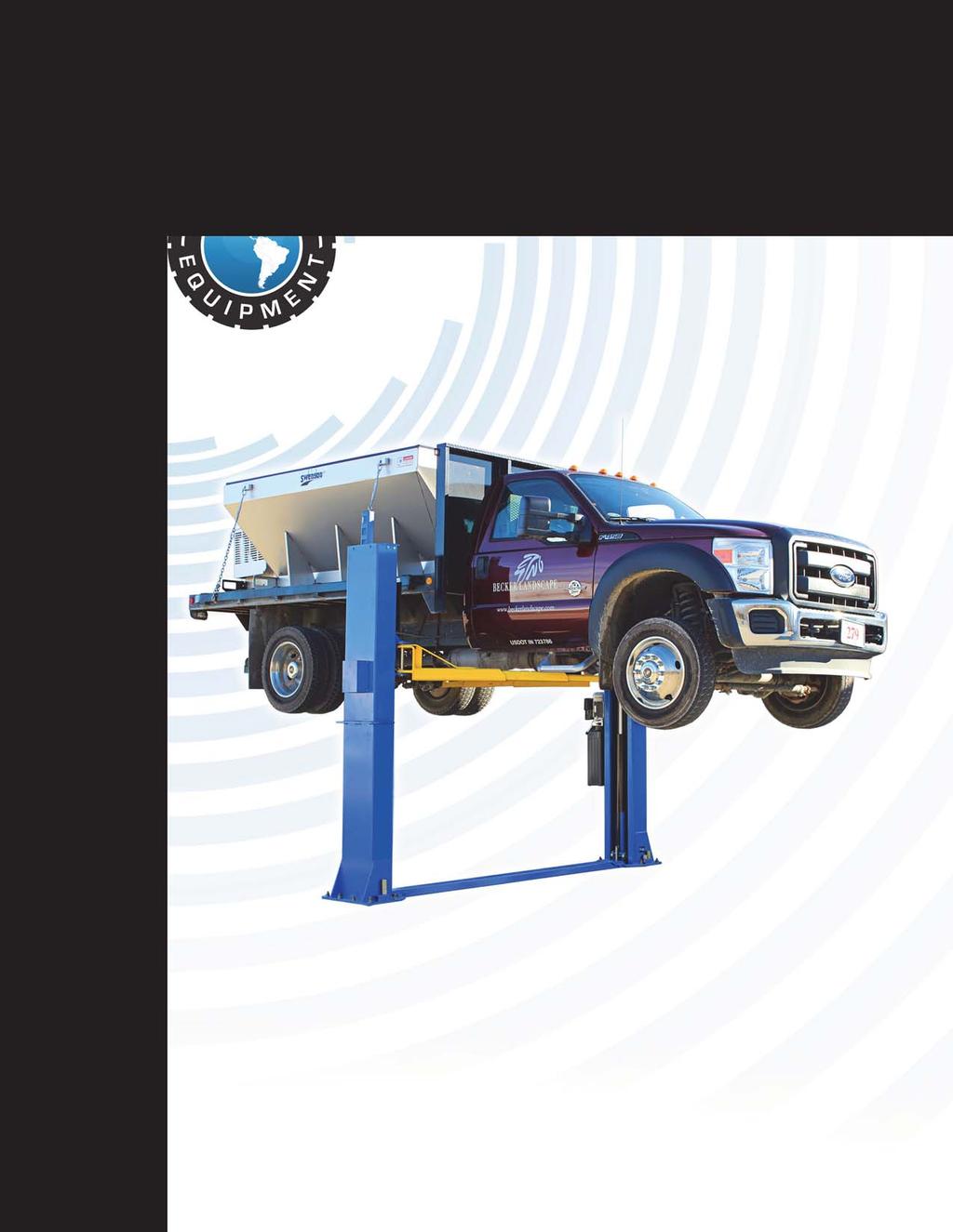
4 Specifications BP12000 Floorplate Chain-Drive Model Features (See Fig. 1) Dual hydraulic direct-drive cylinders, designed and made on ANSI standards, utilizing NOK oil seal in cylinder Self- lubricating UHMW Polyethylene sliders and bronze bushings Single-point safety release, and dual lock safety design Symmetric arm design with 3-stage front and rear arms Convenient width adjustment: Distance between columns /2 (123 1/2 ) and /8 (118 1/8 ) Rubber lift pads with 1.5, 2.5 and 5 stackable extension adaptors Fig. 1 Specifications BP
5 Model BP12000 Specification Model Style Lifting Capacity Lifting Time Lifting Height Overall Height Overall Width Width Between Columns Minimum Pad Height Gross Weight Motor BP12000 Base plate Chain-drive 12,000lbs 55S 73 1/4 82 1/ / / / / /2 4 3/4 2,156lbs 2.0 HP Arm Swing View Fig. 2 Specifications BP


")

 Wrench set (mm)")
 Vise Grips")
6 Installation Requirement Tools Required Rotary Hammer Drill (3/4 ) Carpenter s Chalk Hammer Screw Drivers Level Bar Tape Measure (25ft) Crescent Wrench (12 ) Pliers Ratchet Spanner With Socket (28#) Allen Head Wrench (6#) Wrench set (mm) (10#, 13#, 14#, 15#, 17#, 19#, 24#, 27#) Vise Grips Fig. 3 Installation Requirement BP
7 Specifications Of Concrete (See Fig. 4) Concrete specifications must be adhered to. Failure to do so may result in lift and/or vehicle falling. 1. Concrete must have a minimum thickness of 6 inches. Concrete must be cured before the installation. 2. Concrete must be in good condition and must be of test strength 3,000psi minimum. 3. Floors must be level with no cracks. Fig. 4 Power Supply 220 volt single phase 30 amp breaker with minimum of 10 gauge wire Installation Requirement BP
 Fig. 5 C. Check The Parts Before Assembly 1. Packaged lift and hydraulic power unit (See Fig. 6).")
8 Steps Of Installation A. Location Of Installation Make sure the location of the lift (concrete, layout, space size etc.) is suitable for installation. B. Use A Carpenter s Chalk Line To Establish Installation Layout Of The Base Plate (See Fig. 5) Fig. 5 C. Check The Parts Before Assembly 1. Packaged lift and hydraulic power unit (See Fig. 6). Fig. 6 Steps Of Installation BP
. Shipment Parts list Parts Box Fig. 7 Floor cover 3.")


9 2. Move the lift aside with fork lift or hoist, and open the outer packing carefully (See Fig. 7). Shipment Parts list Parts Box Fig. 7 Floor cover 3. Remove the parts from the upper and inside of the column. Remove the parts box, and check the parts according to the shipment parts list (See Fig. 8). Serial No. Fig Loosen the bolts of the upper package stand, take off the upper column and remove the package stand. Steps Of Installation BP

 Fig.")
10 5. Move aside the parts and check the parts according to the shipment parts list (See Fig. 9, 10). 84 Parts in the shipment parts list Fig. 9 Parts in the parts box (84) Fig. 10 Steps Of Installation BP


.")
11 6. Open the parts bag and check the parts according to parts bag list (See Fig. 11). Fig. 11 D. Position Power Side Columns Lay down two columns on the installation site parallel, position the power side column according to the actual installation site. Usually, it is suggested to install power side column on the right side. Install the top plates (See Fig.12). Offside column Power side column Car-in direction Assemble top plate using M12*30 hex bolt with nut and washer. Fig. 12 Steps Of Installation BP


. Washer Lock washer Fig.")
12 E. Position The Columns Check The Columns For Plumb With A Level Bar, And Adjust With The Shims If The Columns Are Not True (See Fig. 13) Note: Set the width to 145 3/8 or 150 ¾ Adjust the columns to vertical with the shims 118 1/8 or 123 1/2 54 Check the columns plumb (front and side) with level bar Fig /8 or 150 3/4 F. Fix Anchor Bolts 1. Prepare anchor bolts (See Fig. 14). Washer Lock washer Fig. 14 Nut Steps Of Installation BP

 Power side safety device Fig.")
13 2. Use a rotary hammer drill and ¾ masonry bit. Drill all the anchor holes and install the anchor bolts. Tighten the anchor bolts between 60 and 86 foot pounds. Fig. 15 G. Install Safety Locks (See Fig. 16 & 17) Power side safety device Fig. 16 Offside safety device Fig. 17 Steps Of Installation BP


14 H. Lift The Carriages Up By Hand And Lock Them At The Same Level (See Fig. 18) Safety device locked at the same level Fig. 18 Steps Of Installation BP
15 I. Install Cable According to step E (Width Setting) choose the width distance of your lift (See Fig.13). Note: Follow cable routing diagram below 1. For width distance with 150 3/4 (See Fig.19). Fig. 19 Steps Of Installation BP
16 2. For width distance with 145 1/ Pass the cable through from the bottom to the top of the carriage. The cable passes through the hole of the carriages and is screwed with two cable nuts. (See Fig. 20). Fig. 20 Steps Of Installation BP
. Fig.")
17 2.2. Pass the cable through as shown below (See Fig. 21). Fig. 21 Steps Of Installation BP
 Note: Install the safety cable from the offside safety first.")
18 J. Install The Cable On The Safety Locks (See Fig. 22) Note: Install the safety cable from the offside safety first. Pay attention to the pass through direction. Fig. 22 Steps Of Installation BP

19 K. Install Hydraulic Power Unit And Oil Hose Assembly (See Fig. 23) Fig. 23 Tighten all the hydraulic fittings, and fill the reservoir with hydraulic oil. Note: Use hydraulic oil AW46. Steps Of Installation BP

20 L. Install Floor Cover (See Fig. 24) Note: Choose different extension cover according to the columns distance. Installation for 123 1/2 columns distance: Use long extension cover to connect the floor cover. Installation for 118 1/8 columns distance: Use short extension cover to connect the floor cover. Fig. 24 Steps Of Installation BP
. 2. Lower the carriages down to the lowest position, then use the 8mm allen wrench to")
. 4.")
. Use an 8mm allen wrench Snap spring Fig. 25 Fig.")
21 M. Install Lifting Arms And Adjust The Arm Locks 1. Install the lifting arms (See Fig. 25). 2. Lower the carriages down to the lowest position, then use the 8mm allen wrench to loosen the nut of arm lock (See Fig. 26). 3. Adjust the arm lock as arrow direction (See Fig. 27). 4. Adjust the moon gear and arm lock so they mesh together, then tighten the bolts on the arm lock. (See Fig. 27). Use an 8mm allen wrench Snap spring Fig. 25 Fig. 26 Adjust the Arm lock Lock the nuts after the moon gear and arm lock engaged well Fig. 27 Steps Of Installation BP

22 2. Install toe guard Fig. 28 N. Install Electrical System V single phase motor 1.1. Circuit diagram (See Fig. 29). Fig. 29 Steps Of Installation BP

23 1.2. Connection step (See Fig. 30) a. Connect the two power supply lines (fire wire L and zero wire N) to the terminals on the AC contactor marked L1, L2. b. Terminal 3# of control button is connected with terminals L1 of AC contactor; Terminal 4# of control button is connected with terminals A1 of AC contactor. Fig Connection diagram (See Fig. 31). Fig. 31 Steps Of Installation BP

24 Exploded View Car in Fig. 32 Exploded View BP

25 Cylinder Fig. 33 Atlas Hydraulic Power Unit 220V/60HZ/1Phase Fig. 34 Exploded View BP


26 Illustration Of Hydraulic Valve For Atlas Hydraulic Power Unit Atlas hydraulic power unit, 220V/60HZ, Single phase (See Fig. 35) Oil return port Check valve Oil Outlet Protective ring Release valve Handle for Release valve Relief valve Throttle valve Fig. 35 Exploded View BP


27 Test Run 1. Adjust synchronizing cable Use a wrench to hold the cable fitting, and use another wrench to tighten the cable nut. Make sure the two cables have the same tension. If the carriage does not synchronize when lifting, please tighten the cable nut of the lower side carriage. (See Fig. 36) Cable nut 2. Adjust safety cable Fig. 36 Lift the carriage and lock at the same height. Strain the safety cable, release a little, and then tighten the cable nuts. Make sure the safety locks can always work properly. 3. Adjust the lower speed (Only for Atlas power unit) You can adjust the lower speed of the lift if needing: Loosen the Fixing Nut of the throttle valve, and then turn the throttle valve clockwise to decrease the lower speed, or counterclockwise to increase the lower speed. Do not forget to tighten the fixing nut after the lower speed adjustment has been done. Throttle Valve Fixing Nut Clockwise to decrease the down speed Fig. 37 Counterclockwise to increase the down speed Test Run BP

28 4. Test with load After finishing the above adjustment, test run the lift with a load. Run the lift in low position several times first, make sure the lift can rise and lower at the same time, the safety device can lock and release at the same time. Test run the lift to the top completely. If there is anything improper, repeat the above adjustment. Fig. 38 Hydraulic System Test Run BP
29 Operation Instructions Please read the safety tips carefully before operating the lift To lift vehicle 1. Keep work area free of clutter; 2. Position lift arms to the lowest position; 3. Open lift arms; 4. Position vehicle between columns; 5. Move arms to the vehicle s lifting points; Note: The four lift arms must at the same time contact the vehicle s lifting points where manufacturers recommended 6. Press the UP button until the lift pads contact underside of vehicle totally. Recheck to make sure vehicle is secure; 7. Continue to raise the lift slowly to the desired working height, ensuring the balance of vehicle; 8. Push lowering handle to lower lift onto the nearest safety. The vehicle is ready to repair. To lower vehicle 1. Keep work area free of clutter; 2. Press the button of UP to raise the vehicle slightly, and then release the safety device, lower vehicle by pushing lowering handle. 3. Open the arms and position them to the shortest length; 4. Drive away the vehicle. Operation Instructions BP
30 Maintenance Schedule Monthly: 1. Re-torque the anchor bolts between 60 and 86 foot pounds; 2. Check all connectors, bolts and pins to insure proper mounting; 3. Lubricate cable with lubricant; 4. Make a visual inspection of all hydraulic hoses/lines for possible wear or leakage; 5. Check Safety device and make sure proper condition; 6. Lubricate all Rollers and Pins with 90wt. Gear oil or equivalent; Note: All anchor bolts should take full torque. If any of the bolts does not function for any reason, DO NOT use the lift until the bolt has been replaced. Every six months: 1. Make a visual inspection of all moving parts for possible wear, interference or damage. 2. Check equal tension of the cables and adjust as necessary to insure level lifting. 3. Check columns are plumb. 4. Check Rubber Pads and replace as necessary. 5. Check safety locks and make sure they are in proper condition. Maintenance Schedule BP
31 Trouble Shooting TROUBLE CAUSE REMEDY Motor does not run Motor runs but the lift is not raised Lift does not stay up Lift raises slowly Lift cannot lower 1. Button does not work 2. Wiring connections are not in good condition 3. Motor burned out 4. AC contactor in damage 1. Motor runs in reverse rotation 2. Gear pump out of operation 3. Release valve in damage 4. Relief valve or check valve in damage 5. Low oil level 1. Release valve out of work 2. Relief valve or check valve leakage 3. Cylinder or fittings leakage 1. Oil line is jammed 2. Motor running on low voltage 3. Oil mixed with air 4. Gear Pump leaks 5. Overload lifting 1. Safety device are locking. 2. Release valve in damage 3. Safety cable broken 4. Oil system is jammed 1. Replace button 2.Repair all wiring connections 3. Repair or replace motor 4. Repair or replace 1.Reverse two power wire 2.Repair or replace 3. Repair or replace 4.Repair or replace 5.Fill reservoir Repair or replace 1. Clean the oil line 2. Check electrical system 3. Fill tank 4. Repair or replace 5. Check load 1. Release the safeties 2. Repair or replace 3. Replace 4. Clean the oil system Trouble Shooting BP
32 Parts List Item Part# Description Qty. Note (See Fig. 32, Fig.12-13, Fig.16-17, 19-23) Floor cover Short extension cover Long extension cover Top pulley Bronze bush for pulley Hair pin Self locking nut Washer Hex bolt A Power side column Power unit Cup head bolt Powerside lock cover A Bronze bush for chain pulley Split Pin Pin for Chain pulley Chain pulley Chain pulley bracket assembly Carriage Cylinder Slider block Carriage plastic cover Protective Rubber Bolt B Arm pin 4 25A Snap spring Socket bolt Lock washer 22 Parts List BP
33 Item Part# Description Qty. Note Washer Moon gear A Lifting arm 4 30A A Outer lifting arm 4 30B A Middle lifting arm 4 30C A Inner lifting arm Hex bolt A Rubber pad assembly 4 32A Socket bolt 4 32B Rubber Pad 4 32C B Rubber Pad frame support assembly Snap Ring Hair Pin Arm lock A Spring B Left arm lock bar C Right arm lock bar Arm lock bar ring A Chain connector Chain Hex bolt Top plate assembly Pin for bottom pulley Big Pulley A Offside column Offside safety cover B Adapter B Adapter B Adapter Hex bolt Washer Self locking nut Shim Pin for safety lock 2 Parts List BP
34 Item Part# Description Qty. Note A Safety Spring Snap ring Plastic small pulley Power side safety lock A Hex nut Handle Protective Plastic cushion Offside safety lock Self locking nut Washer Lock washer Socket bolt Pulley bracket Plastic small pulley Hex bolt Cable Cable nut Safety cable Plastic small pulley Oil hose Fitting for power unit Rubber ring Hex bolt fitting Extend straight fitting fitting Oil hose 2 81A Oil hose T fitting A Anchor Bolt A Parts box Toe guard Bolt Lock Washer 8 Parts List BP
35 Item Part# Description Qty. Note Parts For Hydraulic Cylinder (See Fig. 33) Piston rod Piston O-Ring Support Ring Y-Ring O-Ring Hex nut Adjustment tube Dust ring O-Ring Head cap Bleeding Plug O-Ring Bore weldment 2 Parts For Atlas Manual Power Unit, 220V/60Hz, 1 phase (See Fig. 34) Motor Start capacitor A Run capacitor AC contactor Allen bolt Motor fix frame A Motor connecting shaft Valve body A Relief valve Throttle valve A Lock washer A Allen bolt Inlet pipe A O-Ring A Filter bolt 4 Parts List BP
36 Item Part# Description Qty. Note Reservoir Cover of motor terminal box Protective ring A Push button Screw A Oil return port A Oil outlet A Release valve A Handle for release valve A Washer A Nut A Check valve Gear pump Oil return pipe Filler cap 1 Parts List BP

37 Warranty This item is warranted for five (5) years on structural components, two (2) years on hydraulic cylinders, and one (1) year on electric or air / hydraulic power units from invoice date. Wear items are covered by a 90 day warranty. This LIMITED warranty policy does not include a labor warranty. NOTE: ALL WARRANTY CLAIMS MUST BE PRE-APPROVED BY THE MANUFACTURER TO BE VALID. The Manufacturer shall repair or replace at their option for this period those parts returned to the factory freight prepaid, which prove after inspection to be defective. This warranty will not apply unless the product is installed, used and maintained in accordance with the Manufacturers installation, operation and maintenance instructions. This warranty applies to the ORIGINAL purchaser only, and is non-transferable. The warranty covers the products to be free of defects in material and workmanship but, does not cover normal maintenance or adjustments, damage or malfunction caused by: improper handling, installation, abuse, misuse, negligence, carelessness of operation or normal wear and tear. In addition, this warranty does not cover equipment when repairs or alterations have been made or attempted to the Manufacturer s products. THIS WARRANTY IS EXCLUSIVE AND IS LIEU OF ALL OTHER WARRANTIES EXPRESSED OR IMPLIED INCLUDING ANY IMPLIED WARRANTY OR MERCHANTABILITY OR ANY IMPLIED WARRANTY OF FITNESS FROM A PARTICULAR PURPOSE, AND ALL SUCH IMPLIED WARRANTIES ARE EXPRESSLY EXCLUDED. THE REMEDIES DESCRIBED ARE EXCLUSIVE AND IN NO EVENT SHALL THE MANUFACTURER, NOR ANY SALES AGENT OR OTHER COMPANY AFFILIATED WITH IT OR THEM, BE LIABLE FOR SPECIAL CONSEQUENTIAL OR INCIDENTAL DAMAGES FOR THE BREACH OF OR DELAY IN PERFORMANCE OF THIS WARRANTY. THIS INCLUDES, BUT IS NOT LIMITED TO, LOSS OF PROFIT, RENTAL OR SUBSTITUTE EQUIPMENT OR OTHER COMMERCIAL LOSS. PRICES: Prices and specifications are subject to change without notice. All orders will be invoiced at prices prevailing at time of shipment. Prices do not include any local, state or federal taxes. RETURNS: Products may not be returned without prior written approval from the Manufacturer. DUE TO THE COMPETITIVENESS OF THE SELLING PRICE OF THESE LIFTS, THIS WARRANTY POLICY WILL BE STRICTLY ADMINISTERED AND ADHERED TO. Warranty BP
Read this entire manual before operation begins.
 Read this entire manual before operation begins. Record below the following information which is located on the serial number data plate. Serial No. Model No. Date of Installation Contents Specifications.............
Read this entire manual before operation begins.
 Read this entire manual before operation begins. Record below the following information which is located on the serial number data plate. Serial No. Model No. Date of Installation Contents Specifications.............
Read this entire manual before operation begins.
 Read this entire manual before operation begins. Record below the following information which is located on the serial number data plate. Serial No. Model No. Date of Installation Contents Specifications.............
Atlas PV-9WP Addendum
 Atlas PV-9WP Addendum 9,000 lb. Capacity Two-Post Overhead Lift The Atlas PV-9WP above ground hoist is 6 inches wider than the Atlas PV-9P, giving it an overall width of 141 (11 9 ) and a drive thru width
Read this entire manual before operation begins.
 Rev. 12/12/2017 Read this entire manual before operation begins. Record below the following information which is located on the serial number data plate. Serial No. Model No. Date of Installation Contents
CONTENTS. Product Features and Specifications...1. Installation Requirement Steps of Installation.. 5. Exploded View Test Run...
 CONTENTS Product Features and Specifications...1 Installation Requirement... 3 Steps of Installation.. 5 Exploded View...18 Test Run...21 Operation Instruction...22 Maintenance... 23 Trouble Shooting...
Read this entire manual before operation begins.
 Read this entire manual before operation begins. Record below the following information which is located on the serial number data plate. Serial No. Model No. Date of Installation Contents Specifications.............
CONTENTS. Product Features and Specifications...1. Installation Requirement Steps of Installation.. 5. Exploded View Test Run...
 CONTENTS Product Features and Specifications...1 Installation Requirement... 4 Steps of Installation.. 5 Exploded View...21 Test Run...26 Operation Instruction...27 Maintenance... 28 Trouble Shooting...
CONTENTS. Product Features and Specifications Installation Requirement Installation Exploded View Operation Instruction...
 1 CONTENTS Product Features and Specifications... 3 Installation Requirement... 5 Installation... 6 Exploded View... 20 Test... 22 Operation Instruction... 25 Maintenance... 26 Trouble Shooting... 27 Parts
CONTENTS. Product Features and Specifications Installation Requirement Steps of Installation 4. Exploded View Test Run...
 CONTENTS Product Features and Specifications... 1 Installation Requirement... 3 Steps of Installation 4 Exploded View... 14 Test Run... 16 Operation Instruction... 19 Maintenance... 20 Trouble Shooting...
Read this entire manual before operation begins.
 Read this entire manual before operation begins. Record below the following information which is located on the serial number data plate. Serial No. Model No. Date of Installation Contents Specifications.............
CONTENTS. Product Features and Specifications...1. Installation Requirement...3. Steps of Installation...4. Exploded View Test Run...
 TP10AS 2-POST LIFT CONTENTS Product Features and Specifications...1 Installation Requirement...3 Steps of Installation...4 Exploded View...24 Test Run....28 Operation Instruction...29 Maintenance...30
PRO JACK 4500 ROLLING BRIDGE JACK 4,500 POUND CAPACITY. PARTS MANUAL P/n NRJ450BK
 PRO JACK 4500 ROLLING BRIDGE JACK 4,500 POUND CAPACITY PARTS MANUAL P/n NRJ450BK 2007 RJ-45 (M) PARTS LIST Item # Part Number Description Qty 1 NRJ45-1000 Bottom Tray 1 2 NRJ45-2100 Outer Scissor 1 3
30-SS1203A 12,000 LB CAPACITY SCISSOR ALIGNMENT LIFT INSTALLATION AND SERVICE MANUAL P/N:
 WITH STRENGTH 30-SS1203A 12,000 LB CAPACITY SCISSOR ALIGNMENT LIFT INSTALLATION AND SERVICE MANUAL P/N: 420-02553 CONTENTS Product Features and Specifications...1 Installation Requirement...3 Steps of
Installation/Operation/Service Manual
 TLX12/TLX12A Installation/Operation/Service Manual CONTENTS Product Features and Specifications...1 Installation Requirement...3 Steps of Installation...4 Exploded View...23 Test Run...28 Operation Instruction...29
Models PR-12F PR-12C PR-15C SURFACE MOUNTED TWO-POST LIFTS INSTALLATION AND OPERATION MANUAL
 Forward this manual to all operators. Failure to operate this equipment as directed may cause injury. INSTALLATION AND OPERATION MANUAL SURFACE MOUNTED TWO-POST LIFTS Models PR-12F PR-12C PR-15C Keep this
Read this entire manual before operation begins.
 Read this entire manual before operation begins. Record below the following information which is located on the serial number data plate. Serial No. Model No. Date of Installation Contents Specifications.............
Read this entire manual before operation begins.
 Revised 9/5/2018 Read this entire manual before operation begins. Record below the following information which is located on the serial number data plate. Serial No. Model No. Date of Installation Contents
ASSEMBLY & OPERATION INSTRUCTION MANUAL
 LR-26-PAD 6000 lb Capacity Low-Rise Pad Lift ASSEMBLY & OPERATION INSTRUCTION MANUAL 6,000 LB. LOW-RISE PAD LIFT Easy frame lifting on padded runways. Great for wheel and brake work, tire and wheel changing
Models: SURFACE MOUNTED FOUR-POST LIFTS INSTALLATION AND OPERATION MANUAL
 Forward this manual to all operators. Failure to operate this equipment as directed may cause injury. INSTALLATION AND OPERATION MANUAL SURFACE MOUNTED FOUR-POST LIFTS Models: FL-18 BP-18 BP-27/ BP-27A
ASSEMBLY / OPERATION INSTRUCTIONS. Low Profile Motorcycle Dolly
 ASSEMBLY / OPERATION INSTRUCTIONS 1,500LB CAPACITY Low Profile Motorcycle Dolly Model: 03-CG1500-01(B1) WARNING BEFORE USE PLEASE READ ALL WARNINGS AND INSTRUCTIONS TO PREVENT SERIOUS INJURY Drop-Tail
ASSEMBLY / OPERATION INSTRUCTIONS. Low Profile / Stand-Up Motorcycle Dolly
 ASSEMBLY / OPERATION INSTRUCTIONS 1,500LB CAPACITY Low Profile / Stand-Up Motorcycle Dolly Model: 03-CGPR1500-01(C) WARNING BEFORE USE PLEASE READ ALL WARNINGS AND INSTRUCTIONS TO PREVENT SERIOUS INJURY
GLO-8000 SERIES (GLO-8000 & GLO-8000XLT)
") GLO-8000 SERIES (GLO-8000 & GLO-8000XLT) 8,000 LBS. CAPACITY FOUR-POST STORAGE LIFT INSTALLATION & OPERATION MANUAL SERIAL NUMBER: INSTALLATION DATE: EAGLE EQUIPMENT 1-800-336-2776 REV2011 03.0 BD SHIPPING
GLO-8000 SERIES (GLO-8000 & GLO-8000XLT) 8,000 LBS. CAPACITY FOUR-POST STORAGE LIFT INSTALLATION & OPERATION MANUAL SERIAL NUMBER: INSTALLATION DATE: EAGLE EQUIPMENT 1-800-336-2776 REV2011 03.0 BD SHIPPING
GLO-7000 SERIES (GLO-7000 & GLO-7000XLT)
") GLO-7000 SERIES (GLO-7000 & GLO-7000XLT) 7,000 LBS. CAPACITY FOUR-POST STORAGE LIFT (BLUE) INSTALLATION & OPERATION MANUAL SERIAL NUMBER: INSTALLATION DATE: EAGLE EQUIPMENT 1-800-336-2776 (STANDARD) SHIPPING
GLO-7000 SERIES (GLO-7000 & GLO-7000XLT) 7,000 LBS. CAPACITY FOUR-POST STORAGE LIFT (BLUE) INSTALLATION & OPERATION MANUAL SERIAL NUMBER: INSTALLATION DATE: EAGLE EQUIPMENT 1-800-336-2776 (STANDARD) SHIPPING
Model PL-7 / PL-7X AUTOMOBILE STACKER INSTALLATION AND OPERATION MANUAL
 Forward this manual to all operators. Failure to operate this equipment as directed may cause injury. AUTOMOBILE STACKER INSTALLATION AND OPERATION MANUAL Model PL-7 / PL-7X Keep this operation manual
MSC-6KLP Low Profile Mobile Single Column Lift. 6,000 lb. Capacity (1,500 lbs. Max Capacity per Arm) Installation & Operation Manual
 Installation & Operation Manual") Low Profile Mobile Single Column Lift 6,000 lb. Capacity (1,500 lbs. Max Capacity per Arm) Installation & Operation Manual INDEX PREFACE-------------------------------------------------------------------------------
Low Profile Mobile Single Column Lift 6,000 lb. Capacity (1,500 lbs. Max Capacity per Arm) Installation & Operation Manual INDEX PREFACE-------------------------------------------------------------------------------
OWNERS MANUAL HF4263
 OWNERS MANUAL HF4263 ADJUSTABLE AB / BACK HYPER BENCH Note: Both Serial Number and Model Number are Required when Ordering Parts RECORD SERIAL NUMBER HERE CATALOG NUMBER 0805-000 Customer Service (800)
INSTALLATION & OPERATION MANUAL
 Two-Post Clear Floor Lift (Asymmetric) 9,000 lbs. Capacity (2,250 lbs. Max per Arm) INSTALLATION & OPERATION MANUAL IMPORTANT NOTES READ THE INSTALLATION AND OPERATION MANUAL IN ITS ENTIRETY BEFORE ATTEMPTING
Model SL-12K-A SCISSOR LIFT. wheel alignment model. (11000 LBS / 5000Kg Capacity) INSTALLATION & OPERATION INSTRUCTION (SECOND EDITION)
 INSTALLATION & OPERATION INSTRUCTION (SECOND EDITION)") Model SL-12K-A SCISSOR LIFT wheel alignment model (11000 LBS / 5000Kg Capacity) INSTALLATION & OPERATION INSTRUCTION (SECOND EDITION) 2007. 6. CONTENTS Chapter 1 Introduction & Specifications ---------------------------------------
Model SL-12K-A SCISSOR LIFT wheel alignment model (11000 LBS / 5000Kg Capacity) INSTALLATION & OPERATION INSTRUCTION (SECOND EDITION) 2007. 6. CONTENTS Chapter 1 Introduction & Specifications ---------------------------------------
ATTENTION. 1. Do not attempt to use the power unit to extend your cylinder. This must be done manually.
 NSS8XLT Installation Manual ATTENTION By following the instructions in this manual you can save yourself much time, frustration and money. The installation of your lift will take 4-5 hours. Do not rush.
ATD2P11BS. Two-Post Clear Floor Bi-Symmetric Automotive Lift. Installation & Operation Manual. 11,000 lbs. Capacity. (2,750 lbs.
 Two-Post Clear Floor Bi-Symmetric Automotive Lift 11,000 lbs. Capacity (2,750 lbs. Max per Arm) Installation & Operation Manual 1. Safety Information 1.1 Note, Caution and Warning 1.2 Important Information
1300 lb Capacity Trike Lift
 M-1300C-TRIKE 1300 lb Capacity Trike Lift USER S MANUAL TRIKE MOTORCYCLE LIFT An extra wide platform designed especially for three-wheel motorcycles. M-1300-TRIKE Trike Motorcycle Lift SPECIFICATIONS:
ASSEMBLY & OPERATION MANUAL. CDVK2 Power Tower RECORD SERIAL NUMBER HERE
 ASSEMBLY & OPERATION MANUAL CDVK2 Power Tower RECORD SERIAL NUMBER HERE www.inspirefitness.net by Health In Motion LLC Feb. 2011 TABLE OF CONTENTS Section Description.. Page Instructions.. 1 Tools Required
9,000 POUND TWO-COLUMN AUTOMOTIVE LIFT. Model: NW-2-9KACD MANUAL
 9,000 POUND TWO-COLUMN AUTOMOTIVE LIFT Model: NW-2-9KACD MANUAL 1 9,000 POUND CAPACITY MODEL: NW-2-9KACD TWO-COLUMN AUTOMOTIVE LIFT READ THIS ENTIRE MANUAL BEFORE OPERATION BEGINS RECORD BELOW THE FOLLOWING
TP15KC-KX Two-Post Clear Floor Lift
 TP15KC-KX Two-Post Clear Floor Lift (Symmetric) 15,000 lbs. Capacity (3,750 lbs. Max per Arm) ASSEMBLY & OPERATION INSTRUCTION MANUAL Feb. 2017 IMPORTANT NOTES READ THE INSTALLATION AND OPERATION MANUAL
Lifting height 5.5" - 72" with adapters " Height overall 165" Width between columns 122" Drive through 109" Width overall 151.
 Model Number TP12KC-D Capacity 12,000 lbs. Lifting height 5.5" - 72" with adapters 79.625" Height overall 165" Width between columns 122" Drive through 109" Width overall 151.125" Arm extension 37.5" -
MR6K-48X. Mid-Rise Scissor Lift ASSEMBLY & OPERATION INSTRUCTION MANUAL. 6,000 lbs.
 MR6K-48X Mid-Rise Scissor Lift 6,000 lbs. ASSEMBLY & OPERATION INSTRUCTION MANUAL November 2014 Important! Be sure to read the operating instructions before operating your lift! Getting Ready Make sure
Installation and Parts Manual for SPANCO A Series Steel Gantry Cranes
 Manual No. 103-0002 08/14 Installation and Parts Manual for SPANCO A Series Steel Gantry Cranes ISO 9001 REGISTERED 2 TABLE OF CONTENTS Warnings... 3 Assembly and Operation...4 Track Installation Instructions...6
Index. 1. Important safety instructions Overview of the lift Installation instructions Operation instructions 8-9
 2 Index 1. Important safety instructions 4-5 1.1 Safety Warnings 1.2 Qualified personnel 1.3 Safety 1.4 Warning signs 2. Overview of the lift 6 2.1 General descriptions 2.2 Technical data 2.3 Construction
ASSEMBLY & OPERATION INSTRUCTION MANUAL
 Sliding Bridge Jack 3,500 lbs. Capacity ASSEMBLY & OPERATION INSTRUCTION MANUAL TABLE OF CONTENTS Specifications... 2 Description & Features... 3 Installation Instructions... 4 Safety Instructions... 4
203 TRANSFER CASE CONVERSION
 203 TRANSFER CASE CONVERSION PN:501 OUR FOUR TRANSFER CASE WEDGES REPLACE THE SPIDER GEARS AND CONNECT THE PLANETARY GEAR AND REAR OUTPUT SHAFT MAKING ONE UNIT. SIMILAR IN DESIGN & FUNCTION TO THE BEST
Grapple Kit Install & Grapple Bucket Manual
 Grapple Kit Install & Grapple Bucket Manual Model # Serial # Rev. 10/13 Rylind Manufacturing, Inc. 2801 Youngfield St Suite 250 Golden, CO 80401 Business/Sales Offices: 303-979-3548 Manufacturing Plant:
Operating Instructions and Parts Manual SLT-330F Scissor Lift Table
 Operating Instructions and Parts Manual SLT-330F Scissor Lift Table For serial no. 17020001 and higher JET 427 New Sanford Road LaVergne, Tennessee 37086 Part No. M-140771 Ph.: 800-274-6848 Revision C
HSB21 Battery Burnisher
 HSB21 Battery Burnisher OPERATION AND PARTS MANUAL Rev A 01/2003 HS2100 PARTS LIST Item No. Qty Part No. Description 1 1 001 Lower Body Housing 2 1 002 Battery Condition Meter 3 1 003 RPM Meter 4 1 004
OWNERS MANUAL HF4550 PREACHER CURL. Customer Service (800) (858) Fax (858) RECORD SERIAL NUMBER HERE
 (858) Fax (858) RECORD SERIAL NUMBER HERE") OWNERS MANUAL HF4550 PREACHER CURL Note: Both Serial Number and Model Number are Required when Ordering Parts RECORD SERIAL NUMBER HERE CATALOG NUMBER 0805-001 Customer Service (800) 548-5438 (858) 578-7676
OWNERS MANUAL HF4550 PREACHER CURL Note: Both Serial Number and Model Number are Required when Ordering Parts RECORD SERIAL NUMBER HERE CATALOG NUMBER 0805-001 Customer Service (800) 548-5438 (858) 578-7676
Model FP14KO-A Wheel alignment & Open Front Four-Post Lift
 Model FP14KO-A Wheel alignment & Open Front Four-Post Lift ( 14000LBS / 6300Kg Capacity) ASSEMBLY & OPERATION INSTRUCTIONS ( Series T1) 2009.7. INTRODUCTION Model FP14KO-A is a four-post lift is used in
OWNERS MANUAL HF PAIR VERTICAL DUMBBELL RACK. Customer Service (800) (858) Fax (858) RECORD SERIAL NUMBER HERE
 (858) Fax (858) RECORD SERIAL NUMBER HERE") OWNERS MANUAL HF4459 5 PAIR VERTICAL DUMBBELL RACK Note: Both Serial Number and Model Number are Required when Ordering Parts RECORD SERIAL NUMBER HERE CATALOG NUMBER 0605-000 Customer Service (800) 548-5438
OWNERS MANUAL HF4459 5 PAIR VERTICAL DUMBBELL RACK Note: Both Serial Number and Model Number are Required when Ordering Parts RECORD SERIAL NUMBER HERE CATALOG NUMBER 0605-000 Customer Service (800) 548-5438
INSTALLATION INSTRUCTIONS
 INSTALLATION INSTRUCTIONS Thank you for purchasing ROXTERTM Hitch Mounted Mud Flaps. Agri-Cover, Inc. proudly manufactured these mud flaps using superior quality materials and workmanship. With proper
Please visit for the latest version of these installation instructions.
 Please visit www.blueox.com for the latest version of these installation instructions. BX2643 Please read BOTH these and the General Instructions prior to installing or operating this equipment. 1. Blue
BX Jeep Liberty Renegade 2012 Jeep Liberty Sport Installation Instructions
 Attachment Tab Height: 17.5 Attachment Tab Width: 24 Serial Number Please read BOTH these and the General Instructions prior to installing or operating this equipment. 1. Blue Ox towing products and accessories
OWNERS MANUAL HF
 OWNERS MANUAL HF4461-48 HORIZONTAL DUMBBELL RACK Note: Both Serial Number and Model Number are Required when Ordering Parts RECORD SERIAL NUMBER HERE CATALOG NUMBER 1005-000 Customer Service (800) 548-5438
Installation Instructions Capacity 10,000 lbs. (100 Series Lift)
") Installation Instructions Capacity 10,000 lbs. (100 Series Lift) IMPORTANT Reference ANSI/ALI ALIS, Safety Requirements for Installation and Service of Automotive Lifts before installing lift. OPERATING
Installation Instructions Capacity 10,000 lbs. (100 Series Lift) IMPORTANT Reference ANSI/ALI ALIS, Safety Requirements for Installation and Service of Automotive Lifts before installing lift. OPERATING
INSTALLATION INSTRUCTIONS
 INSTALLATION INSTRUCTIONS Thank you for purchasing ROLTECTM Electric Hopper Conversion. Agri-Cover, Inc. proudly manufactured this hardware using superior quality materials and workmanship. With proper
Installation and Parts Manual for SPANCO A Series Steel Gantry Cranes
 Manual No. 103-0002 REV. 3/07 Installation and Parts Manual for SPANCO A Series Steel Gantry Cranes ISO 9001 REGISTERED 2 TABLE OF CONTENTS Warnings... 3 Assembly and Operation...4 Track Installation Instructions...6
Model BP6150. Triplex Ceramic Plunger Pump Operating Instructions/ Manual
 Model BP6150 Triplex Ceramic Plunger Pump Operating Instructions/ Manual Contents: Installation Instructions: page 2 Pump Specs: page 3 Exploded View: page 4 Parts List / Kits Torque Specifications: page
OWNERS MANUAL HF4261
 OWNERS MANUAL HF4261 ADJUSTABLE AB BENCH Note: Both Serial Number and Model Number are Required when Ordering Parts RECORD SERIAL NUMBER HERE CATALOG NUMBER 0905-000 Customer Service (800) 548-5438 (858)
TECHNICAL SERVICE MANUAL
 Electronic copies of the most current TSM issue can be found on the Viking Pump website at www.vikingcom TECHNICAL SERVICE MANUAL abrasive liquid pumps SERIES 4625 SIZES f - fh SECTION TSM 410.1 PAGE 1
PRODUCT OBSOLETED 4Q16
 Electronic copies of the most current TSM issue can be found on the Viking Pump website at www.vikingcom TECHNICAL SERVICE MANUAL abrasive liquid pumps SERIES 4625 SIZES f - fh SECTION TSM 410.1 PAGE 1
IMPORTANT READ ME FIRST
 IMPORTANT READ ME FIRST Thank you for purchasing your Kushlan Mixer. We hope that you will enjoy using it for many years to come. SHOULD YOU REQUIRE ANY SET-UP OR OPERATING ASSISTANCE WITH YOUR PRODUCT,
QJY245DS~DA. Two Post Lift Installation & Adjustment Manual
 QJY245DS~DA Two Post Lift Installation & Adjustment Manual Table of Contents 1. Warning 2 2. Summary 2 3. Use 2 4. Mainly technology parameter 2 5. Basic structure of the production 3 6. Safety device
Dodge SpynTec Hub Conversion Kit
 SpynTec SpynTec Industries Installation Instructions for the Dodge SpynTec Hub Conversion Kit I n d u s t r i e s SpynTec Industries LLC. 11501 South Avenue North Lima, Ohio 4445 1.888.90.AXLE Page 1 Warning
MOTORIZED FOLDING CAMPER WINCH
 OWNER'S MANUAL MOTORIZED FOLDING CAMPER WINCH With 1200lb Lift Capacity The 12 Volt Motorized Folding Camper Winch is used to raise and lower folding campers with the touch of the switch, eliminating hand
CONTENTS. VIKING PUMP, INC. A Unit of IDEX Corporation Cedar Falls, IA USA SECTION TSM 710.1
 TECHNICAL SERVICE MANUAL industrial heavy duty motor speed pumps SERIES 4076 AND 4176 SIZES hle, ate and ale SECTION TSM 710.1 PAGE 1 of 8 ISSUE B CONTENTS Introduction....................... 1 Safety
FLEETWOOD TRAVEL TRAILER SLIDEOUT SYSTEM OWNER S MANUAL
 FLEETWOOD TRAVEL TRAILER SLIDEOUT SYSTEM OWNER S MANUAL 82-S0150-01 REV. 1 April, 2002 TABLE OF CONTENTS PAGE # OPERATIONS MANUAL... 1 1. SYSTEM DESCRIPTION... 1 1.1 MAJOR COMPONENTS... 1 2. HOW TO OPERATE
Please visit for the latest version of these installation instructions.
 Please visit www.blueox.com for the latest version of these installation instructions. 2013-18 Ford C-Max (Includes Hybrid & Energi) Attachment Tab Height: 12 Serial Number Attachment Tab Width: 20 Please
Please visit for the latest version of these installation instructions.
 Please visit www.blueox.com for the latest version of these installation instructions. BX1730 Attachment Tab Height: 16 Serial Number Attachment Tab Width: 23 Please read BOTH these and the General Information
HP30 Slab Saw Owner s Manual and Operating Instructions
 HP30 Slab Saw Owner s Manual and Operating Instructions MADE IN USA Revision 07 09.0 Manual Part No. 67 Caution: Read all safety and operating instructions before using this equipment. This manual MUST
Installation and Parts Manual for SPANCO E Series Gantry Cranes
 Manual No. 103-0004 REV. 1/10 Installation and Parts Manual for SPANCO E Series Gantry Cranes ISO 9001 REGISTERED SPANCO, Inc. TABLE OF CONTENTS Warnings... 3 Assembly Instructions... 4 Serial Number Location...
ATD-2P9A 9,000 lbs. Two Post Clear Floor Lift Owner s Manual
 ATD-2P9A 9,000 lbs. Two Post Clear Floor Lift Owner s Manual Features: Specifications: IMPORTANT NOTES READ THE INSTALLATION AND OPERATION MANUAL IN ITS ENTIRETY BEFORE ATTEMPTING TO INSTALL THE LIFT.
EASY DUMP RD3100 / RD3106 (Standard)-(60/40 Split)-(60/40 Divider)- (70/30 Split with Bayne) USER S MANUAL
-(60/40 Split)-(60/40 Divider)- (70/30 Split with Bayne) USER S MANUAL") EASY DUMP RD3100 / RD3106 (Standard)-(60/40 Split)-(60/40 Divider)- (70/30 Split with Bayne) USER S MANUAL *** Important *** Read User s Manual Completely Prior to Operating Par-Kan Company Phone: 1-800-291-5487
EASY DUMP RD3100 / RD3106 (Standard)-(60/40 Split)-(60/40 Divider)- (70/30 Split with Bayne) USER S MANUAL *** Important *** Read User s Manual Completely Prior to Operating Par-Kan Company Phone: 1-800-291-5487
4400-Lb. Capacity Pallet Jack
 Read carefully and understand all ASSEMBLY AND OPERATION INSTRUCTIONS before operating. Failure to follow the safety rules and other basic safety precautions may result in serious personal injury. Item#
iqpc912 PARTS MANUAL PC912PM v1
 iqpc912 PARTS MANUAL PC912PM v1 See Page 10 See Page 6 & See Page 12 See Page 2 See Page 16 See Page 1 See Page 1 See Page See Page 22 See Page 20 See Page 2 See Page 26 3 16 19 1 17 1 1 11 13 12 10 9
GERINGHOFF. Corn Header Manual f HEADSIGHT.COM
 GERINGHOFF Corn Header Manual 09020701f HEADSIGHT.COM 574.546.5022 About Headsight Headsight Contact Info Headsight, Inc. 4845 3B Road Bremen, IN 46506 Phone: 574-546-5022 Fax: 574-546-5760 Email: info@headsight.com
15H882 Slider Bearing Kit
 Instructions 15H882 Slider Bearing Kit 311616D ENG To replace slider bearings on E-Flo 4-Ball Piston Pumps. For professional use only. Important Safety Instructions Read all warnings and instructions in
MODEL 5120 Tire Repair Station
 MODEL 5120 Tire Repair Station 00-0049 Installation, Operation & Repair Parts Information Branick Industries, Inc. 4245 Main Avenue P.O. Box 1937 Fargo, North Dakota 58103 REV01182017 P/N: 81-0058G CAUTION
4400-Lb. Capacity Extra-Long Pallet Jack
 4400-Lb. Capacity Extra-Long Pallet Jack Owner s Manual WARNING: Read carefully and understand all ASSEMBLY AND OPERATION INSTRUCTIONS before operating. Failure to follow the safety rules and other basic
Owner s Manual & Safety Instructions
 Owner s Manual & Safety Instructions Save Save This This Manual Keep Keep this this manual manual for for the the safety safety warnings warnings and and precautions, assembly, assembly, operating, inspection,
11 ½" MODEL SINGLE CHAIN CONVEYOR
 11 ½" MODEL SINGLE CHAIN CONVEYOR USER S MANUAL 11 ½" Chain conveyor Revision 2011-05-31 2 CONTENTS WARRANTY...3 FOREWORD...4 SAFETY PRECAUTIONS...5 ASSEMBLY INSTRUCTIONS...6 SPECIFICATIONS...6 ASSEMBLING
Owner s Manual. Upper Body Unit. Serial Number Here. Date of Purchase New Hope Road, Raleigh, NC Fusion -
 Revision 3 April 2015 Upper Body Unit Owner s Manual Serial Number Here Date of Purchase www.batcafitness.com 1207 New Hope Road, Raleigh, NC - 919.255.1233 Fusion - www.batcafitness.com 4 Upper Body Station
TECHNICAL SERVICE MANUAL
 Electronic copies of the most current TSM issue can be found on the Viking Pump website at www.vikingpump.com TECHNICAL SERVICE MANUAL industrial heavy duty motor speed pumps SERIES 4076 AND 4176 SIZES
SLAB SAW SERIES PARTS LIST
 SLAB SAW SERIES PARTS LIST MODELS: HP Part# 020 HP20 Part# 02020 HP2 Part# 0202 MADE IN USA MADE IN USA Revision 09.20 Manual Part No. 6269 Caution: Read all safety and operating instructions before using
MODEL EF Full Circle Tire Spreader
 MODEL EF Full Circle Tire Spreader Installation, Operation & Repair Parts Information Branick Industries, Inc. 4245 Main Avenue P.O. Box 1937 Fargo, North Dakota 58103 REV. 062917 P/N: 81-0050C CAUTION
Please visit for the latest version of these installation instructions.
 Please visit www.blueox.com for the latest version of these installation instructions. BX1126 Attachment Tab Height: 14-1/2 Serial Number Attachment Tab Width: 24 Please read BOTH these and the General
LIFT NAME PART NUMBER SETBACK (min) SETBACK (max)
 SETBACK (max)") Revolution 9889 Garrymore Ln Missoula, MT 59808 888-687-3552 +1-406-549-0769 www.aquacreek.com Wheelchair Attachment PART #: F-705S3 WEIGHT CAPACITY: 350 POUNDS - STANDARD REVOLUTION 300 POUNDS - DEEP
Revolution 9889 Garrymore Ln Missoula, MT 59808 888-687-3552 +1-406-549-0769 www.aquacreek.com Wheelchair Attachment PART #: F-705S3 WEIGHT CAPACITY: 350 POUNDS - STANDARD REVOLUTION 300 POUNDS - DEEP
Floor Plate Style Lift And Overhead Beam Style Lift. Two Post Lift
 Floor Plate Style Lift And Overhead Beam Style Lift 9,000 POUND Two Post Lift ASSEMBLY & OPERATION INSTRUCTION TABLE OF CONTENTS Important Note Page 3 Definition Page 4 Preparation and General Information
HIGH DUMP ROLL-OUT BUCKET
 HIGH DUMP ROLL-OUT BUCKET Model # Serial # Rev. 01/14 Rylind Manufacturing, Inc. 2801 Youngfield St Suite 250 Golden, CO 80401 Business/Sales Offices: 303-979-3548 Manufacturing Plant: 970-522-2859 www.rylind.com
Hydraulic Clutch Jack
 Hydraulic Clutch Jack Operating Instructions & Parts Manual Model Number Atd-7404 Capacity 500 Lb. Atd Tools Inc. 160 Enterprise Drive, Wentzville MO 63385 Printed in China ATD7404-M0 05/07 Save these
PT1 Power Trainer ASSEMBLY & OPERATION MANUAL RECORD SERIAL NUMBER HERE
 PT1 Power Trainer ASSEMBLY & OPERATION MANUAL RECORD SERIAL NUMBER HERE www.inspirefitness.net by Health In Motion LLC Dec. 2010 TABLE OF CONTENTS Section Description.. Page Instructions.. 1 Tools Required
Hydraulic Transmission Jacks
 Hydraulic Transmission Jacks Operating Instructions & Parts Manual Model Number Atd-7435 Atd-7436 Atd-7437 Capacity 1100 Lb. 2000 Lb. 3000 Lb. Model Atd-7435 Model Atd-7436 Model Atd-7437 Atd Tools Inc.
Owner s Manual. Upper Body Unit. Serial Number Here. Date of Purchase New Hope Road, Raleigh, NC Fusion -
 Revision 1 March 2012 Upper Body Unit Owner s Manual Serial Number Here Date of Purchase www.batcafitness.com 1207 New Hope Road, Raleigh, NC - 919.255.1233 Fusion - www.batcafitness.com 4 Upper Body Station
MEX (55) QRO (442) Web Controls
 QRO (442) Web Controls") Web Controls SINGLE AND DUAL ROTOR TENSION CONTROL BRAKES MODELS:,,,, AND INSTALLATION, OPERATION, AND MAINTENANCE INSTRUCTIONS Read this manual carefully, making full use of its explanations and instructions.
Web Controls SINGLE AND DUAL ROTOR TENSION CONTROL BRAKES MODELS:,,,, AND INSTALLATION, OPERATION, AND MAINTENANCE INSTRUCTIONS Read this manual carefully, making full use of its explanations and instructions.
INSTALLATION AND SERVICE MANUAL
 INSTALLATION AND SERVICE MANUAL Please fill in for future reference: MODEL: SERIAL NUMBER: DATE PURCHASED: * Please fill out the warranty registration card in this manual or online at www.mdminc.com XXXXXXXXX
Please read BOTH these Installation Instructions and the General Information sheet prior to installing or operating this equipment.
 Attachment Tab Height: 24-1/4 Serial Number Attachment Tab Width: 24 Please read BOTH these and the General Information sheet prior to installing or operating this equipment. 1. Blue Ox towing products
WARNING. BX Buick Lacrosse Installation Instructions. Bolt Torque Specifications. Bolt Torque Specifications
 Please read BOTH these and the General Instructions before attempting to install or operate this equipment. 1. Blue Ox towing products and accessories are intended to be installed by Blue Ox Dealers who
Please visit for the latest version of these installation instructions.
 Please visit www.blueox.com for the latest version of these installation instructions. BX1728 2017-18 GMC Acadia (Includes Denali & All-Terrain) (No Limited) Attachment Tab Height: 16 Serial Number Attachment
Please visit for the latest version of these installation instructions.
 Please visit www.blueox.com for the latest version of these installation instructions. BX1986 Please read BOTH these and the General Information sheet prior to installing or operating this equipment. 1.
LifeGuardLift. LifeGuard Power Lift Model #100287A OWNERS MANUAL. Rev: 2/14/11
 LifeGuardLift OWNERS MANUAL LifeGuard Power Lift Model #100287A Rev: 2/14/11 Table of Contents 1. ASSEMBLY INSTRUCTIONS A. Lift Assembly B. Setup C. Disassembly 2. CONTROL SYSTEM A. Batteries B. Battery
General Medium Duty KLM C&C 2-Stage Rear Air Suspension Installation Instructions
 2686 Highway 92 - Oskaloosa, IA 52577 Phone: 641.673.0468 - Fax: 641.673.4168 www.kelderman.com General Medium Duty KLM 10745 C&C 2-Stage Rear Air Suspension Installation Instructions Class 6 & 7 Trucks
Operating Instructions and Parts Manual Long Chassis Service Jacks
 Operating Instructions and Parts Manual Long Chassis Service Jacks Models JSJ-3T/JSJ-5T/JSJ-10T WMH TOOL GROUP 2420 Vantage Drive Elgin, Illinois 60123 Part No. M-454430 Ph.: 800-274-6848 Revision A 8/05
Hydraulic Bead Breaker Kit
 Hydraulic Bead Breaker Kit Owner s Manual WARNING: Read carefully and understand all ASSEMBLY AND OPERATION INSTRUCTIONS before operating. Failure to follow the safety rules and other basic safety precautions