Disc Mower Conditioner
|
|
|
- Angel Edwards
- 5 years ago
- Views:
Transcription


1 Disc Mower Conditioner Form Replaces ~ ~ ~ [Q1 ~ (g) ~ OPERATOR'S AND. '.' SERVCE PARTS MANUAL J W L!J


2 GEHL. COMPANY New Agricultural Equipment Gehl Company (ncorporated), hereinafter referred to as GEHL, as manufacturer of quality machinery since 1859, warrants new GEH L machinery andl or attachments at the time ofdelivery to the original purchaser to be free from defects in material and workmanship if properly set up and operated in accordance with the recommendations set forth in GEHL's Operator Manual. GEHL's liability for any defect with respect to accepted goods shall be limited to repairing the goods at an authorized GEH L dealer or other GEHL designated location, or replacing them, as GEH L shall elect. The above shall be in accordance with GEH L warranty adjustment policies. GEH L's obligation shall terminate twelve (12) months after the delivery of the goods to the original purchaser. This warranty shall not apply to any machine or attachment which shall have been repaired or altered outside the G EH L factory or authorized GEH L dealership or in any way so as in GEH L'sjudgment. to affect its stability or reliability, nor which has been subject to misuse, negligence or accident, nor to any machine or attachment which shall not have been operated in accordance with GEHL's printed instructions or beyond the company recommended machine rated capacity. This warranty shall not be applicable to items which are subject to the warranties of their respective manufacturers. Such items would include but would not be limited to engines, clutches, universaljoints, knives, hydraulic components, bearings, tires, belts and other trade accessories. EXCLUSON OF WARRANTES Except as otherwise expressly stated herein, GEH L makes no representation or warranty ofany kind, express or implied, AND MAKES NO WARRANTY OF MERCHANTABLTY N RESPECT TO TS MACHNERY AND/OR ATTACHMENTS AND MAKES NO WARRANTY THAT TS MACHlNERY AND/ OR ATTACHMENTS ARE FT FOR ANY PARTCULAR PURPOSE. GEHLshallnot be liable for incidental or consequential damages for any breach of warranty, including but not limited to inconvenience, rental or replacement equipment, loss of profits or other commercial loss. GEHL shall not be liable for, and the buyer assumes all liability for, all personal injury and property damage resulting from the handling, possession or use of the goods by the buyer. No agent. employee or representative of GEHL has any authority to bind GEHL to any affirmation, representation or warranty concerning its machinery andl or attachments except as specifically set forth herein.
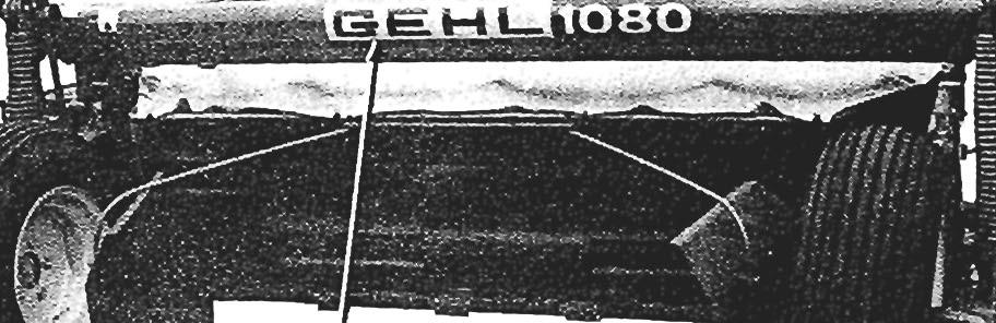
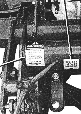
3 NTRODUCTON Mr. Operator: Your decision to purchase this piece ofg EHL equipment was a good one. We are sure that your decision was strongly considered and that you are looking forward to many seasons of work from this machine. We, as a Company, have invested a great deal oftime and effort in developing our lines offarm equipment and Skid Steer Loaders. The equipment you have purchased is built with a great deal of pride and designed to give you long life, efficient operation, durability and dependability. This manual was developed specifically for the machine you have purchased. The information, contained within, was prepared for your assistance in preparing, adjusting, maintaining and servicing your machine. More importantly, this manual provides an operating plan for safe and proper use of your machine. Major points of safe operation are detailed in the SAFETY chapter of this manual. Refer to the Table of Contents for an outline of this manual. Farm machinery has become more sophisticated and, with that in mind, GEHL Company asks that you read and understand the contents of this manual COMPLETELY and become familiar with your new machine, BEFORE attempting to operate it. Our wide Dealership network stands by to provide you with any assistance you may require, including genuine GEHL service parts. All parts should be obtained from or ordered through your GEHL Dealer. Give complete information about the part as well as the model number and the serial number of your machine. Record numbers, in the space provided, as a handy record for quick reference. "Right" and "Left" are determined from a position standing behind the Conditioner and facing the direction of travel. From this position, the Drawbar is on the "Left" side. Typical Model & Serial Plate 1 00.'," 0 C1 080 SERAL NO. (Fill n) GEHL COMPANY WEST BEND, WS U.S.A. GEHL Company reserves the right to make changes or improvements in the design or construction of any part without incurring the obligation to install such changes on any unit previously delivered. Throughout this manual, information is provided which is set in bold type and introduced by the word NOTE. BE SURE to read carefully and comply with the message or directive given. Following this information will improve your operating or maintenance efficiency, help you to avoid costly breakdown or unneccessary The GEHL Company, in compliance with the Farm and ndustrial Equipment nstitute and the American Society of Agricultural Engineers, has adopted the SAFETY ALERT SYMBOL to pinpoint characteristics which, if not properly followed, can create a safety hazard. When you see this symbol in this manual or on the unit itself, you are reminded to BE ALERT! Your Safety is involved. TABLE OF CONTENTS Page Warranty... nside Front Cover ntroduction... 3 Specifications...4 Check Lists Safety General nformation Service Parts Decal Locations Numerical ndex ndex... nside Back Cover Numbers for this unit are stamped on a plate located on the left Frame member next to the Cylinder Rod Yoke. 3
4 SPECFCATONS All Dimensions are in nches (Millimeters) Unless Otherwise Noted Power... From 540 RPM 50 hp (37 kw) tractor and hydraulic circuit Overall Length (Approximate) (4572) Operating Height (Approximate) /2 (1206) Transport Height /2 (1384) Cutting Width...94 (2400) Transport Width (2950) Tracking Width...89 (2250) Cutting Height... Adjustable from 1-1/2 to 3-3/4 (38 to 95) Weight (Approximate) b (1177 kg) Number of Discs...6 Disc Speed RPM at 540 PTO RPM Total N urn ber of Knives Knive Overlap /4 (l08) Knife Tip Speed mph (280 kmh) Oil Capacities: Gearbox U.S. Gallons (5 liters) Cutterbar U.S. Gallons (2.25 liters) Roller Speed RPM Tires... Two 10/80 x 12SR 4-Ply Tires on 7.00 x 12 Rims (Before Serial #2303) or Two 10/75 x 15SR 6-Ply Tires on 9.00 x 15 Rims (After Serial #2301) Ground Travel Speed... 6 mph (9.5 kmh) or faster as conditions permit Standard Features: Slip Clutch protected Telescoping PTO Drive Free-wheeling Overrunning Clutch in Disc and Roller Drive Line Heavy synthetic flexible Protective Sheet Guard over the Cutterbar Built-in and replaceable Stone Guard Plate on the Cutterbar Cutterbar Knives have a'5 twist to lift the cut material over the Cutterbar. Adjustable Skid Shoes to regulate cutting height Adjustable Cutterbar Flotation Hydraulic Cylinder Cutterbar lift control Repositionable Windrow Shields 4
5 CHECK LSTS.;... o -... (1) :;: cv l. :;( > a. o U ~ Lllli "... (1) 'ii Q) o (1) > o E Q) a: - PRE-DELVERY After the Disc Conditioner has been completely set-up, the following inspections should be made before delivering it to the Customer. Check off each item after prescribed action is taken. Check that: _~ Disc Conditioner has been com pletely and properly set-up according to details in this manual. _~ All Grease Fittings have been properly lubricated and that the Gearbox and Cutterbar have been filled to their proper operating levels; see the Lubrication information. _~ All Guards, Shields and Decals are in place and securely attached. _~ All fasteners are properly secured. _~ All adjustments have been made to comply with settings given in the Adjustments information. _~ Record the Serial Number of this unit on this page and page 3. Hook the Disc Conditioner up to a 540 RPM tractor and test-run the unit while checking that proper operation is exhibited by all components. Check that: _~ All Blades, Discs and Rollers are turning freely. All Mechanisms are operating smoothly. The Hydraulic Hose connection is NOT leaking under pressure and that lift mechanism is operating smoothly and properly. DELVERY The following Check List is an important reminder of valuable information that MUST be passed on to the Customer at the time the unit is delivered. Check off each item as you explain it to the Customer. _~ Give the Customer his Operator's Manual. nstruct him to be sure to read and completely understand its contents BEFORE attempting to operate his unit. Explain and review with him the SAFETY information. Explain to him that regular lubrication is required for continued proper operation and long life. Review with him the Lubrication information in this manual. Explain to him the function of the Overrunning Clutch on the end of the PTO and the Slip Clutch on the Gearbox input. _~ Explain to him the function and value of the PTO Safety Chain, the Safety Clamp on the Transport Tube and flexible Sheet Cutterbar Protective Guard. _~ Explain the importance of proper tractor PTO shaft to Disc Conditioner Gearbox Drive Shaft alignment. Demonstrate the proper use of the Locking Couplers on both ends of the Telescoping PTO Drive. Completely fill out Owner's Registration, including Customer's signature, and return it to the GEHL Company. acknowledge that pre-delivery service was performed on this unit as outlined above. acknowledge that above points were reviewed with me at the time of delivery. Dealer's Name By Dealer's Set-up Man's Signature Date Delivered Customer's Signature Date Set-up ~~ ~ Serial N umber (Dealer's File Copy) 5
6 6 NTENTONALLY BLANK (T0 be removed as Dealer's File Copy)
7 CHECK LSTS PRE-DELVERY After the Disc Conditioner has been completely set-up, the following inspections should be made before delivering it to the Customer. Check off each item after prescribed action is taken. Check that: Disc Conditioner has been completely and properly set-up according to details in this manual. All Grease Fittings have been properly lubricated and that the Gearbox and Cutterbar have been filled to their proper operating levels; see the Lubrication information. All Guards, Shields and Decals are in place and securely attached. All fasteners are properly secured. All adjustments have been made to comply with settings given in the Adjustments information. Record the Serial Number of this unit on this page and page 3. Hook the Disc Conditioner up toa 540 RPM tractor and test-run the unit while checking that proper operation is exhibited by all components. Check that: All Blades, Discs and Rollers are turning freely. All Mechanisms are operating smoothly. The Hydraulic Hose connection is NOT leaking under pressure and that lift mechanism is operating smoothly and properly. acknowledge that pre-delivery service was performed on this unit as outlined above. DELVERY The following Check List is an important reminder of valuable information that MUST be passed on to the Customer at the time the unit is delivered. Check off each item as you explain it to the Customer. Give the Customer his Operator's Manual. nstruct him to be sure to read and completely understand its contents BEFORE attempting to operate his unit. Explain and review with him the SAFETY information. Explain to him that regular lubrication is required for continued proper operation and long life. Review with him the Lubrication information in this manual. Explain to him the function of the Overrunning Clutch on the end of the PTO and the Slip Clutch on the Gearbox input. Explain to him the function and value of the PTO Safety Chain, the Safety Clamp on the Transport Tube and flexible Sheet Cutterbar Protective Guard. Explain the importance of proper tractor PTO shaft to Disc Conditioner Gearbox Drive Shaft alignment. Demonstrate the proper use of the Locking Couplers on both ends of the Telescoping PTO Drive. Completely fill out Owner's Registration, including Customer's signature, and return it to the GEHL Company. acknowledge that above points were reviewed with me at the time of delivery. Dealer's Name By Dealer's Set-up Man's Signature Date Set-up Serial Number Customer's Signature Date Delivered (Note: Pages 5 and 6 Have Been Removed at Perforation) 7


8 SAFETY BEFORE YOU ATTEMPT TO OPERATE THS EQUPMENT, READ AND STUDY THE FOLLOW NG SAFETY NFORMATON. N ADDTON, MAKE SURE THAT EVERY NDVDUAL WHO OPERATES OR WORKS WTH THS EQUPMENT, WHETHER FAMLY MEMBER OR EMPLOYEE, S FAMLAR WTH THESE SAFETY PRECAUTONS. GEHL Company always takes the operator and his safety into consideration when designing farm machinery and guards exposed moving parts for his protection; however, some areas cannot be guarded or shielded in order to assure proper operation. n addition, the operator's manual and decals on the machine itself warn you of further danger and should be read and observed closely. The safety alert symbol above means ATTENTON! BECOME ALERT! YOUR SAFETY S NVOLVED! t stresses an attitude of"heads UP" for safety and can be found throughout this operator's manual and on the unit itself. Remember: The careful operator is the best operator. Most accidents are caused by human error. Certain preca utions must be observed to prevent the possibility of injury or damage. Please read the rules listed below for safe operation BEFORE you operate this equipment. Use of the word CAUTON, WARNNG or DANGER herein and on the machine itself signals three degrees of hazard. CAUTON is used for general reminders of good safety practices or to direct attention to unsafe practices. WARNNG is used to denote a specific potential hazard. DANGER is used to denote the most serious specific potential hazard. MANDATORY SAFETY SHUTDOWN PROCEDURE Work of any type on machinery is always more dangerous when the machine is operating. Therefore, unless otherwise expressly instructed to the contrary, BEFORE cleaning, adjusting, lubricating or servicing this unit, the following MANDATORY SAFETY SHUTDOWN PROCEDURE should ALWAYS be followed: 1. Disengage the tractor PTO 2. Shut off the tractor engine 3. Wait for all movement to stop 4. Remove the Telescoping Drive Connection from the tractor PTO shaft ONLY when you have taken these precautions can you be sure it is safe to proceed. Failure to follow the above procedure, could lead to death or serious bodily injury! Some photographs, used herein, mayshow Door(s), Guard(s), or Shield(s) open or removed for illustration purposes ONLY! BE SURE that all Door(s), Guard(s), or Shield(s) are in their proper position, BEFORE the machine is operated! Know how to STOP Disc Conditioner operation BEFORE attempting to start it! BE SURE that the PTO Locking Couplers are properly locked onto the tractor and Disc Mower nput Shafts BEFORE starting the tractor engine! The operator MUST be seated on the tractor BE FORE starting and while operating the unit! BE SURE ALL Guards, Shields and Doors are in place and properly secured BEFORE starting the tractor engine! BEFORE cleaning, adjusting, lubricating or servicing this unit, exercise the following MANDATORY SAFETY SHUTDOWN PROCEDURE: disengage the tractor PTO, stop the tractor engine, make sure ALL movement has STOPPED and remove the Telescoping Drive from the tractor PTO shaft! DO NOT allow minors to operate or be near the Disc Conditioner unless properly supervised! DO NOT allow personnel other than a qualified operator near the Disc Conditioner! DO NOT attempt to clean, adjust or lubricate the Disc Conditioner when any part is in motion! DO NOT wear loose or baggy clothing when operating the Disc Conditioner! DO NOT open any Guards or Shields when the unit is running! DO "~OT attempt to operate the Disc Conditioner unless the Guard Tube on the PTO is chained to the tractor! DO NOT work under the machine unless the Safety Clamp is installed in the Transport Tube! DO NOT exceed a maximum speed of 20 mph (32 kmh) when transporting the Disc Conditioner! DO NOT attempt to hook a 1000 R PM tractor on this unit! 8
9 The following abbreviations are used in this manual. FHSCS - Flat Head Socket Cap Screw HFLS - Hexagon Flanged Lock Screw HHCS - Hexagon Head Cap Screw RHMS - Round Head Machine Screw SHCS - Socket Head Cap Screw CN - Castellated Nut HFLN - Hexagon Flanged Lock Nut HJN - Hexagon Jam Nut HLN - Hexagon Lock Nut HN - Hexagon Nut NLN - Nylon nsert Lock Nut LW - Lock Washer SW - Star Washer General Bolt Torque Data in Ft-Lb BOLT GRADE SZE Metric GENERAL NFORMATON DRY LUB. DRY LUB. DRY LUB. M M MO M M M *Multiply by (1.383) for metric N-m _ The GEHL DC08Q Disc Conditioner is a machine that can mow, condition and windrow in one operation.. The Disc Conditioner is a trailing type machine which is mounted on two wheels and designed to be driven by a standard 540 RPM tractor PTO. The Conditioner Drawbar angle can be conveniently changed from the tractor seat by means of a Control Cord to switch between the transport and operating positions. Cutterbar height is raised or lowered using a tractor control hydraulic Lift Cylinder (provided). Cutting height and ground pressure are independently adjustable. The mowing portion of the Disc Conditioner is composed of six cutting discs which all are revolving in opposite directions next to each-other. After the crop is cut, it is taken up by the Rubber Rollers and conditioned between the Rollers. Once out of the Rollers, the crop is windrowed on the ground by adjustable position Windrow Shields. On leafy andthick-s.!e.ri.lm.~d. rops, the leaves dry faster than the stems. By conditioning the stems, moisture loss is accelerated and the dryingpnycess is evened out to help prevent excessive leaf los8_ A good method for measuring the conditioning effect is to check the crop next to the ground. Take a few stalks and hold them horizontally; the top ends should bang down.. PREPARNG THE TRACTOR To help insure a stable connection between the tractor and the Disc Conditioner, a fixed-::position tractor drawbar should be used. li1addition,the.length of the drawbar MUST also be properly. a~j:u.sted.. A CAUTON: BE SURE that the tractor is.. equipped with proper guarding above and on both sides of the PTO. For operating the hydraulic Lift Cylinder, a 3/8 x 1-1/2 pipe coupling and. the appropriate quick-disconnect (NOT provided) MUST be attached to the Lift Cylinder Hose. Use Teflon tape on fitting to. help prevent leaks. MOUNTNG TO THE TRACTOR n order for the Disc Conditioner to be properly connected to a tractor, the Conditioner Tongue Hitch position MUST be properly established with respect to the height of the tractor drawbar and fixed distance between the PTO shaft and drawbar. Proper positioning of the Conditioner Hitch involves appropriate orientation and attachment of the Conditioner Hitch Clips to the Tonque. Tractor Hitch Clip PTO Shaft Mounting Surface h 14" 22-5/8"rl (356mm) (575mm) " to 12" (152W~m~m~)~~~~3f======~=F~~ See Chart 1 #2 7 /' 7 7 #3 ~~P:r======i=::::P Fig. 1: Hitch Clip Setup Hitch Clip Tractor Drawbar Height Mounting From #1 #2 #3 #4 Ground. 12(305) 14(356) 15(381 ) 18(457) 141h(368)Min. 12(305) 15(381) 16(406) 18(457) 15(381 ) 13(330) 16(406) 17(432) 19(483) 16(406) 14(356) 17(432) 18(457) 20(508) 17(432) 15(381) 18(457) 19(483) 21(533) 18(457) 16(406) 19(483) 20(508) 22(559) 19(483) 17(432) 20(508) 21(533) 23(584) 20(508) 18(457) 20(508) 21(533) 24(610) 203fs(518) Max Fig. 2: Tractor Orawbar Height Table with All Dimensions in n. (mm) 9
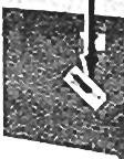
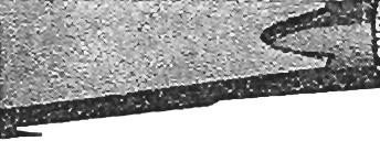
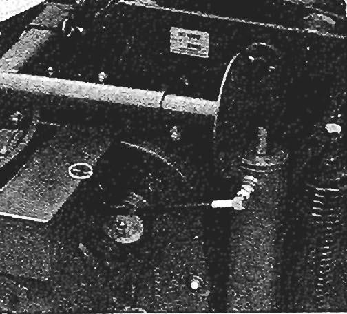
10 To establish the correct Hitch Clip orientation, the first step is to know (by measurement) the actual tractor drawbar height or distance from the ground to the top of the tractor drawbar. With the tractor drawbar height known, the correct Hitch Clip mounting height can be established for proper Conditioner flotation. Once this measurement is obtained, the dimension can be located in the "Tractor Drawbar Height" table to determine which Hitch Clip position will be required. Then, bolt the Hitch Clips to the Conditioner tongue in the appropriate position #1, #2, #3 or #4, as shown. NOTE: Where the same height is listed in the table, BE SURE to select the appropriate required Hitch Clip position (#1, #2, #3 or #4) which will bring the Conditioner PTO Shaft more closely into alignment with the tractor PTO shaft. Tractor drawbar to PTO shaft distances may vary from 6 to 12". For a 6" tractor drawbar to PTO distance, select the minimum Hitch Clip mounting height, or for a 12" tractor drawbar to PTO distance, select the maximum Hitch Clip mounting height. The drawbar of the tractor should be adjusted to a distance of 14" (356 mm) from the end of the PTO shaft to the center of the drawbar hole (Fig. 3). When the PTO shaft to drawbar hole distance is 14" (356 mm) the Conditioner Tongue should be attached in the farthest extension for a distance of22-5/8 (575 mm) between the Gearbox nput Shaft to the Clevis holes. TRANSPORT POSTON Fig. 3 The Disc Conditioner Drawbar can be adjusted four positions (Fig. 4). The far left position (A) is for transport. The Drawbar Locking Catch can be operated by a pull cord attached to the tractor. Lower the Conditioner and pull the Cord to release the Catch and drive the Conditioner ahead or back to reposition the Drawbar. The tractor drawbar can be placed either to the left or the right to position the Conditioner Drawbar into transport. NOTE: Because of large tractor sizes, the 14" (356 mm) PTO shaft to drawbar hole distance might NOT be achieved. n this situation only, the tractor drawbar can be set to 16" (406 mm) and the conditioner Tongue MUST be set back to a distance of 20-1/16" (510 mm). Fig. 4 10
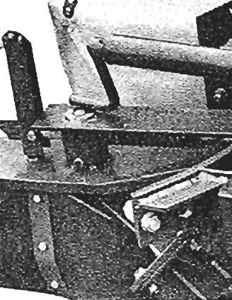
11 The Disc Conditioner can be raised and lowered with the hydraulic Lift Cylinder provided. Attach the Cylinder Hose through a quick-disconnect to the tractor (2 of Fig. 5). The Hose is fitted with a standard 3/8 Pipe Nipple. To route the Hose properly, the "Lead-eye" is mounted on to the front of the Conditioner Drawbar (3 of Fig. 5). Before transporting the Disc Conditioner, move the Draw bar to position "A" (Fig. 4), then the unit should be raised with the hydraulic Lift Cylinder. When in the transport position, the unit MUST be locked up with a Lock Clamp (4 of Fig. 6), fitted around the Spindle of the Cutterbar Pressure Adjustment and secured with the Springclip (5 of Fig. 6). The Lock Clamp provides a positive mechanical lock to hold the Conditioner in the transport position. BE SURE to remove the Lock Clamp before attempting to lower the Conditioner to the operating position. A CAUTON: BEFORE disconnecting the Conditioner from the tractor, BE SURE to relieve hydraulic pressure in the Lift Cylinder. A WARNNG: ALWAYS secure the Disc Con ditioner Lift Cylinder in the transport posi tion with the Lock Clamp and Spring Clip BEFORE proceeding to work under the unit. Fig. 5 Fig. 6 WHEEL PRESSURE AND DRAWBAR POSTONS The amount of applied pressure on the Wheels is directly related to the position of the Drawbar (Fig. 7). A - Transport Position B - Operating Position for use with tractor with a 70 7/8" (1800 mm) trackwidth C - Operating Position for use with tractor with a 59" (1500 mm) trackwidth D - Operating Position for use with any trackwidth tractor on sloping land With the Flotation Springs, the pressure on the Wheels can be influenced. Two holes are provided on the Axle Supports to further adjust the pressure on the Wheels. Proper Flotation Springs and Drawbar setting are as listed: When the Drawbar is set in position B, place the Flotation Springs in the left and the right rear hole positions on the Axle Supports. When the Drawbar is set in position C, place the Flotation Springs in the left and the right front hole positions on the Axle Supports. When the Drawbar is set in position D, place the left Flotation Spring in the rear hole position on the left Axle Support and the right Flotation Spring in the front hole on the right Axle Support. When the Disc Conditioner is attached in a given position on the tractor, it is possible to carry-out a simple test by lifting the unit (by hand) on the right side near the Windrow Shield. The weight should be approximately llo lb (50 kg) (2 of Fig. 4) adjusted by the Wing Nut on the Ground Pressure Adjustment (3 of Fig. 4). Refer to the following topic for additional information. 11
12 Front Front Fig. 7 GROUND PRESSURE The Cutterbar ground pressure is adjustable by means of a Spindle ( of Fig. 8). The pressure can be adjusted as follows:. First raise the Conditioner with the hydraulic Lift Cylinder. 2. Loosen (unlock) the Lock Wing Nut (3 of Fig. 8). 3. Rotate the bottom Wing Nut Handle counterclockwise to increase pressure and clockwise to decrease pressure (Figs. 9 & 10). 4. After the desired pressure is adjusted, BE SURE to lock the pressure setting by tightening the Lock Wing Nut (3 of Fig. 8). NOTE: rregular cutting can occur as a result of either driving too fast for conditions or because of too little pressure on the Cutterbar. When the Skids clearly display deep tracks in the ground, the Cutterbar pressure is definitely set too strong; reduce the pressure. Fig. 8 12
13 Fig. 9 Fig. 11 A CAUTON: MOWNG Fig. 10 BE SURE to check the entire area for spectators and/or obstructions BEFORE proceeding to mow the crop. Choose the appropriate tractor speed and PTO speeds for travel of approximately 6 mph (9.5 kmh). The cutting height will vary, depending on the Hitch Clip mounting height. (Refer to the "Mounting to the Tractor"topic for appropriate mounting details). The cutting height can be adjusted with the Skids on both ends of the Cutterbar (Figs. & 12). Fig. 12 Position A gives a minimum cutting height Position F gives a maximum cutting height Positions B thru E adjusts the cutting height by 7/16" increments. Start into the crop with the Cutterbar raised. Then, engage the tractor PTO and allow the engine R PM buildup to the recommended speed before lowering the Cutterbar and proceeding to cut. NOTE: omitted. Figs. 13 & 14 have been intentionally 13
14 RUBBER CONDTONER ROLLERS The Top Roller serves two purposes; it determines the distance between the Rollers and it also determines the pressure on the Rollers. While the Rollers are turning, they MUST NOT touch. The in.itial adjustment for proper Roller gap is factory set ( of Fig. S). Should adjustment be required, use the Castellated Nut (2 of Fig. 15) and readjust the space. For more gap between the Rollers, loosen the Locking Nut (3 of Fig. S) and rotate the Castellated Nut clockwise. Retighten the Locking Nut. Any gap adjustment made should be carried-out on both ends of the Rollers in order to maintain equal pressure. After the adjustment has been made, test-run the unit at proper operating speed. By adjusting the Roller pressure the conditioning operation can be increased or decreased using the M20 Bolts (Fig. 15). First loosen the Locking Nut (5 of Fig. 16). Rotate the Bolt clockwise (4 of Fig. 16) for more tension and higher conditioning operation or rotate the Bolt counterclockwise for less tension and lesser conditioning operation. To ensure even conditioning along the full width of the Roller distance, both ends of the Roller should be adjusted the same amount "," " " " Fig
15 o 465 b (210 kg) 13/32" (10 mm) 375 b (170 kg) 25/32" (20 mm) 285 b (130 kg) 1-3/16" (30 mm) 190 b (85 kg) 1-9/16" (40 mm) 88 b (40 kg) Fig. 16 SWATHDOORS The width of the Windrow Shields is adjusted between 25-3/4" (650 mm) and 55-1/8" (1400 mm)(l of Fig. 17). A total of 10 equally spaced holes (Figs. 18, 19 & 20) are provided to adjust the Shields in the desired positions. Press the Steel Bar downward and move it to a different hole as desired (Fig. 21). Fig
16 Fig. 18 Fig MaXimumh> ~ 55-1/8" (1400 mm) Fig. 19 KNFE CHANGNG A CAUTON: Exercise the MANDATORY SAFE TY SHUTDOWN PROCEDURE (page 8) BEFORE PROCEEDNG. GEHL Disc Conditioners are equipped with twisted Knives which are designed to provide the lowest cutting level. n general, the Knives can be operated when the Cutterbar is in the flat horizontal position. Both clockwise rotating and counterclockwise rotating Knives are used. Knives are marked with direction of rotation Fig. 21 arrows (Fig. 22). All GEHL Knives are double-edged and reversible. As the Discs are rotating in opposite directions next to each other, the direction of rotation of all Knives MUST be followed exactly, to insure the best cutting action. The Knife Bolts can be loosened with the wrench provided. To facilitate Knife assembly or removal, place the Cutterbar up by placing the unit in the transport position and installing the Lock Clamp in the Mowerbed Pressure Adjustment. A WARNNG: BE SURE to install the Lock Clamp in the Mowerbed Pressure Adjustment when the Conditioner is raised in the transport position and lock the Clamp with the Springcllp. Fig
17 NOTE: BE SURE to use only GEHL replacement Knives, to insure the best cutting action and promote long life. To make Disc stationary while loosening the Knife Bolt, temporarily stop the Disc with a wooden wedge or hammer handle (Fig. 23) l Lilllilimmmmlill 1HHfli Ground Fig f a satisfactory stubble height adjustment can NOT be obtained by adjusting the Skids, recheck and (if necessary) readjust the Conditioner Drawbar. Refer to the "Mounting to the Tractor" topic for details. Setting the Drawbar to the proper height will help to eliminate double and triple cutting. 5. f a build-up of dirt, grass or trash exists, remove it and wash down the Cutterbar before or after the Conditioner is operated. A WARNNG: Be extremely careful while cleaning the Cutterbar area. Use a screwdriver (and NOT your hands) to breakup any dirt build-up or to loosen twisted grass. NEVER remove the Cutterbar Protective Sheet. 6. The Cutterbar Protective Sheet should be adjusted so that it just touches the ground (Fig. 25). Fig f the cutting height is irregular, adjust the travel speed slower or raise the ground pressure of the Cutterbar. f cutting quality decreases, make the following inspections:. Check that the Discs are running at full speed, that the tractor PTO speed is proper and that the ground travel speed is appropriate for conditions. Excessive travel speed can greatly affect the quality of cut. 2. Check that the Knives are the proper rotation, are sharp and are full size. 3. Check the cutting height and make the necessary readjustment on the Skids on both sides (Fig. 24). Fig
18 OL LEVEL the start of each season of operation. Check the oil level each morning before starting the unit; this is desirable to The Gearbox ( of Fig. 26) and the Cutterbar (2 of Fig. allow the oil to settle overnight. A decal is provided which 26) are filled to the correct operating level with HD90 oil displays the correct procedure to follow for checking the before shipment. Oil should be drained and replaced at oil in the Cutterbar. Fig. 26 FLLNG PLUGS & OL CONTENTS A CAUTON: Exercise the MANDATORY SAFE TY SHUTDOWN PROCEDURE (page 8) BEFORE proceeding The Disc Conditioner Gearbox is provided with Plug A for filling and ventilation (Fig. 27), Plug B for checking the oil level (which should be maintained at approximately 1.3 U.S. Gallon or 5 liters) and Plug C for draining the oil. The Cutterbar is provided with Plug D (Fig. 28) for filling, Plug E for checking the oil level (which should be maintained at approximately 0.6 U.S. Gallons or 2.25 liters) and Plug F for draining the oil. NOTE: Plug E and Plug F can be removed using the metric Allen wrench furnished in the Toolbox. To check the oil level in Cutterbar area, first take the Jack and lock it into the Hub on the right side of the Conditioner (Fig. 29). Raise the unit, with the Jack so that the Front Hinge is 13-3/4" (350 mm) off the ground. Leave the Conditioner stand overnight and the oil will settle. Then, in the morning check if the oil level has reached the plug opening (E) (Fig. 28). Replenish the oil level if necessary. Fill & Ventillation Hole Use 1.3 U.S. Gallons (5 Liters) of Oil Level Check Hole Fig. 27: Gearbox Plug Locations 18
 of Oil Level Check Hole Oil Drain 13-3/4\" Hole _~~~~~~==~:: ~(3:5~0~m~m~)1- ~~~ Ground DRANNG AND FLLNG A CAUTON:")

 until the oil starts to show at the level check Plug E. Then, replace Plugs D and E.")


19 Fill & Ventillation Hole - Use 0.6 U.S. Gallons (2-1/4 Liters) of Oil Level Check Hole Oil Drain 13-3/4" Hole _~~~~~~==~:: ~(3:5~0~m~m~)1- ~~~ Ground DRANNG AND FLLNG A CAUTON: Exercise the MANDATORY SAFE TY SHUTDOWN PROCEDURE (page 8) BEFORE proceeding Place the Disc Conditioner on an angle as previously described, remove Plug F and drain the oil. To improve the oil flow, loosen Plug E. When the Cutterbar has been drained, replace Plug F and fill the Cutterbar from Plug D with 0.6 U.S. Gallons (2.25 liters) until the oil starts to show at the level check Plug E. Then, replace Plugs D and E. NOTE: Use a good grade of HD90 oil and avoid overfilling, since this could cause excessive heat build-up and could result in possible damage to the mechanism. Fig. 28: Cutterbar Plug Locations BOLT & HARDWARE CHECK A CAUTON: Exercise the MANDATORY SAFE TY SHUTDOWN PROCEDURE (page 8) BEFORE proceeding. After the Disc Conditioner has been operated for approximately hour, all attaching hardware should be checked and retightened. Hardware torque should be checked on a routine basis after every 10 hours of operation (Fig. 30). Fig. 29: Jack Being Used to Check Cutterbar Oil Level NOTE: Because the Cutting Knives rotate at a speed of 3000 RPM, proper Knife Bolt torque MUST be maintained at 65 ft-b (90 Nm). Check also that the Gearbox Bolts are torqued to 180 ft-b (250 Nm) and the Bolts on the Mower Discs are torqued to 65 ft-b (90 Nm). 19


.")
20 !t8 0 -= -1 ~ \ l g Fig. 34 ~ Fig. 35 Fig. 36 TOOLBOX SUPPLES Fig. 30 The following items are supplied in the Toolboxwhen the unit is delivered: a Drawbar, Skid and Upper Roller Adjustment Wrench, a Drain Plug Wrench, the ~ow~rbed Pressure Adjustment Lock Clamp and Spnngchp,. 9 Counterclockwise rotating Knives and 9 Clockwise Rotating Knives, 4 extra Knife Bolts and 4 extra Knife Bolt Nuts. ~ $ Fig. 37 Fig. 38 SLP CLUTCH SERVCE After long periods of Conditioner storage and before the start of each season of use, the Slip Clutch MUST be activated to insure that it is free to slip and avoid transmitting excessive torque because of sticking Plates. To activate the Clutch, first remove the Shield over the Slip Clutch assembly to gain access for tightening the (4) Nuts on the back of the Clutch assembly (Fig. 39). Then, with the tractor hooked-up, momentarily engage the PTO at idle and observe that the Friction Plates are free. When this observation is made, the (4) Nuts can be untightened and restored to their original condition before replacing the Shield. The unit is now ready to resume operation. Fig. 31 Fig. 32 Fig. 33 Fig. 39: Slip Clutch with Shield Removed 20


21 LUBRCATON A CAUTON: Exercise the MANDATORY SAFE TY SHUTDOWN PROCEDURE (page 8) BEFORE proceeding. The Disc Conditioner MUST be routinely lubricated to promote long life and smooth operation. All points illustrated should be lubricated after every JO hours of operation. Grease Fittings are provided in the following areas: 5 on the Telescoping PTO on the Mid-Bearing on the Overrunning Clutch 2 on the Double Yoke J on the Gearbox on each side of the Lower Roller on each side of the Upper Roller NOTE: The Fitting on the left side of the Upper Roller is designed specifically to purge contamination from the left end Bearing Seal. While greasing, rotate the Upper Roller (by hand), to distribute grease and insure a purge. n more adverse conditions of contamination, this Fitting should be lubricated more frequently. Apply oil to the following points every 10 hours: the Catch on the Drawbar Quadrant, the Drawbar Hinge Joint, the Cylinder pivot points, the Flotation Spring Slides, the PTO Slide Pin and PTO Splines. When placing the Disc Conditioner into storage, BE SURE to thoroughly lubricate the entire unit. n addition, place the Drawbar and Yoke in the position shown (in the last lubrication drawing) and disconnect the Slip Clutch; see Slip Clutch Service topic. ["----~/ ~ n addition to the Fittings, the Telescoping PTO Drive Profile Tube should be greased regularly so that the mating members slide freely. J 21
22 DC DRAWBAR, DRVE SHAFT & JACK )] // r U.ed be'o S ;., #2335 ~//45 61 ~ ~~~ @ c:?~ *2~~@1fii 14 r~ 'Use Threading loctlte 271 (Purchase locally or by GEHl # MPORTANT: Order by Part Number - DO NOT use llustration Reference Numbers. 22
23 DC DRAWBAR, DRiVE SHAFT & JACK Ref. Part Ref. Part Part Name Req. Part Name Req Lynch Pin Grommet HFLS 12.9/MO x (Used after Serial #2334) HFLS2.9/M4x Shield HFLS 12.9/ M 14 x (Used after Serial #2334) HFLS 8.8/M6 x HFLN 12/M14... NLN 8/M20... HFLN 12/ M External Snap Ring A35 x A Shield.... (Used before Serial #2335) Pin (Used after Serial #2334).... Pin (Used before Serial #2335).... Pin (Used after Serial #2334) A Spring A Pin (Used before Serial #2335) Release Lever Cap (Used after Serial #2334) Compression Spring Jack - Assembled Spring (Used after Serial #2334) Ring toA Jack - Assembled Lock Pin (Used before Serial #2335) Drive Shaft Jack Tube Bushing (Used after Serial #2334) Lower Drawbar Beak Jack Tube Bracket (Used before Serial #2335) Top Drawbar Beak Jack Screw Clamp... (Used after Serial #2334) Guard Plate Jack Screw Release Rope (Used before Serial #2335) Toolbox Jack Crank Jack Handle (U sed after Serial #2334) (Used only before Serial #2335) Jack Crank Hose Clamp (Strap).... (Used before Serial #2335) (5 used only before Serial #2335) Jack Pad Flange (Used after Serial #2334) Bearing Jack Pad Pin... (Used before Serial #2335) Pop Rivet 4 x Washer.... (to used only before Serial #2334) (U sed after Serial #2334) Roll Pin 10 x Washer Roll Pin 4 x (Used before Serial #2335) (Used only after Serial #2334) Roll Pin 6 x Roll Pin 6 x RHMS 8.8/M8 x (Used only before Serial #2335) Pin (Used after Serial #2334) Pin (Used before Serial #2335)... Washer... " '1 HHCS8.8/M8x HHCS 8.8M 10 x NLN 10jMO HHCS 8.8/MO x Bushing HHCS8.8/MlOx Quadrant HHCS 8.8/ M 10 x Drawbar HHCS8.8jMOx90... (Used after Serial #2334) HHCS8.8jM14x Drawbar HHCS 8.8/M6 x A A (U sed before Serial #2335) SW (Used after Serial #2334) LW (Used before Serial #2335)... Bolt (Used after Serial #2334).... Bolt (Used before Serial #2335).... Grease Fitting.... Bearing Block.... (Used after Serial #2334) Bearing Block.... (Used before Serial #2335) A (U sed after Serial #2334) HHCS 8.8/ M 16 x (Used before Serial #2335) HHCS 8.8/ M20 x HHCS 8.8/ M20 x HN 8/ M8 Plated... (8 used before Serial #2335) HN8/MO... 6 A For replacement, order current part
24 DC1080 MAN FRAME, WHEELS & WNDROWERS - MPORTANT: Order by Part Number - DO NOT use llustration Reference Numbers. -""'D \ r@/ 9.o.J! --~ i \
25 DC MAN FRAME, WHEELS & WNDROWERS Ref. Part Ref. Part Part Name Reg. Part Name Reg HFLS 12.9/ M 10 x Tire 10.0/75 x 15 SR-6 Ply HFLS2.9/M2x (Used after Serial #2301) HFLS2.9/M2x Tire 10.0/80 x 12 SR-4 Ply HFLN 12/ M (Used before Serial #2302) NLN 8/M Rim 9.00 x (Four used before Serial #2335) (Used after Serial #230 ) NLN 8/M Rim 7.00 x HFLS 12.9/ M 16 x (Used before Serial #2302) (Used after Serial #2334) Left Wheel Mount HFLS l2.9/m6 x (Used after Serial #2334) (Used before Serial #2335) Left Wheel Mount Rear Cover Frame.... (Used before Serial #2335) Front Cover Frame Swivel Axle.... (Used after Serial #2378) (Used after Serial #2334) Front Cover Frame Swivel Axle.... (Used before Serial #2379) (Used before Serial #2335) Left Swathdoor Left Strip Right Swathdoor Buffer Retainer Wheel Hub Buffer..., Adjusting Rod Canvas Cover Spacer (Used after Serial #2378) Washer Canvas Cover Pin... 2 (Used after Serial #2334 & before Bushing Serial #2379) Spacer Bushing A Plastic Protective Sheet Bushing... '"... 2 (Used before Serial #2335) Large Bushing Side Left Plate Wheel Bolt (Used after Serial #2334) Washer S ide Left Plate Bearing RS (Used before Serial #2335) HFLS2.9jM2x Side Right Plate Roll Pin 5 x (Used after Serial #2334) NLN 10/M Side Right Plate Right Strip (Used after Serial #2301 & before (Used after Serial #2301) Serial #2335) Right Strip Side Right Plate.... (Used before Serial #2302) (Used after Serial #2199 & before Frame.... Serial #2302) (Used after Serial #230 ) HHCS8.8/M8x Frame.... (Four used before Serial #2302) (Used before Serial #2302) HHCS 8.8/MO x Strip HHCS 8.8/MlO x (U sed after Serial #230 ) HHCS8.8/M10x Plate HHCS 8.8/ MO x (U sed after Serial #230 ) HHCS 8.8/M2 x Cover HHCS8.8iM14x (Used after Serial #2301) HHCS 8.8/ M20 x nnertube 10.0 x HN 8!M (U sed after Serial #230 ) HJN8/M nnertube 10.0 x 12.," Cotter Pin 3.2 x (Used before Serial #2302) A For replacement, order current part. 25
26 DC LFT SYSTEM MPORTANT: Order by Part Number - DO NOT use ljustration Reference Numbers ~-25 o /~ Detail A ifj- Ref. Part Ref. Part Part Name Req. Part Name Req HFLS 12.9/M 14 x RolPinOx HFLN 12/ M Roll Pin 10 x Connector G3/8 x Roll Pin 5 x Hydraulic Hose Roll Pin 6 x 36..., Crank Roll Pin 6 x " Crank Roll Pin 6 x Yoke..., Roll Pin 18 x Yoke..., Pin (Used after Serial #2334) Spring Pin (Used before Serial #2335) Spring LynchPin..., Flow Restrictor (Used after Serial #2334) Collar Pin (Used after Serial #2334) Shaft A Pin (Used before Serial #2335) Pin B Hydraulic Cylinder - Assembled Pin Tube (Used after Serial #2334) U-Profile A Hydraulic Cylinder - Assembled Bushing (Bearing)... 2 (Used before Serial #2335) Bushing (Bearing) Cotter Pin 5 x Float Control Rod... A For replacement, order current part Roll Pin lox B For components, see page
27 DC HYDRAULC CYLNDER MPORTANT: Order by Part Number - DO NOT use llustration Reference Numbers., ! 7 6 : t : L --.l 4 8 9~--Jir"" Ref. Part Ref. Part Part Name Req. Part Nameq Req A A Hydraulic Cylinder - Assembled Piston Rod.... (Used after Serial #2334) (U sed after Serial #2334) Hydraulic Cylinder - Assembled A Piston Rod.... (Used before Serial #2335) (Used before Serial #2335) Consists of: Piston Sieve.... (Used after Serial #2334) Piston Guide A Piston.... CircJip.... (Used before Serial #2335) Piston Nut M20 x , Seal Kit.... Set Screw (Plug).... (Used after Serial #2334) Cylinder Tube A Seal Kit.... (Used after Serial #2334) (Used before Serial #2335) Cylinder Tube... :.... (Used before Serial #2335) A For replacement, order current part. 21
28 DC TRANSMSSON & MD-SECTON DRVE ~ 15 MPORTANT: Order by Part Number - DO NOT use llustration Reference Numbers. Ref. Part Part Name Req. J External Snap Ring Washer Retaining Ring... (Used only before Serial #2335) Center Cross Elbow Grease Fitting Retainer Ring Spacer Ring... 2 (J used before Serial #2335) Gear (17T)... " Gear (22T) Retaining Ring...,... 3 (Only 1 used before Serial #2335) Key BO x Spacer 63 x 80 x Oil Seal 35 x 72 x 12A... (Used only before Serial #2335) Dust Cap..., Bearing Mid-Section Drive - Assembled Ref Part Part Name Req. yoke.... Overrunning Clutch.... Universal "H".... Spacer Ring...,... (Used only before Serial #2335) Shaft (Used after Serial #2334)... Shaft (Used before Serial #2335) Bearing RS...,.... (U sed after Serial #2334) Bearing. ".,... 2 (Used before Serial #2335) Bearing N U P (Used after Serial #2334) Bearing.... (Used before Serial #2335) Oil Seal 40 x 80 x 10C.... (Used after Serial #2334) Seal.... (Used before Serial #2335)
29 DC ROLLER DRVES Upper Roller Drive 18 8 MPORTANT: Order bv Part Number - DO NOT use llustration Reference Numbers. 21 * 17 2 Lower Roller Drive Use Threading Loclile 271 (Purchased locally or by GEHL #610497) Ref. Part Part Name Reg. Ref. Part Part Name Reg nternal Snap Ring , Bearing Flange , Gear (48T) Gear (37T) Protection Ring Key lox Oil Seal 50 x 80 x loa Ball Beari ng Flange Ring Bushing Cover , External Snap Ring A O-Ring 72, 62 x 3, Seal 40 x 80 x loa Cover w / Grease Point Gease Fitting Shaft (U sed after Serial #2334).... Shaft (Used before Serial #2335)... nternal Snap Ring 1.32 xl,s.... ( Used after Serial #23 34) nternal Snap Ring (Used before Serial #2335) SHCS 10.9/ M 10 x SHCS 10.9/ M 10 x
30 DC1080 CUTTERBAR DRVE 14 1l~ n l 1 '- lj A J MPORTANT: Order by Part Number - DO NOT use llustration Reference Numbers. 'Use Threading loctite 271 (Purchased locally or by GEHl #610497) ~:\-' --..-"...,-----": Detail A Ref. Part Part Name Req. Ref. Part Part Name Req Bearing RS O-Ring Retaining Ring Grease Seal Ring Snap RingA Ball Bearing , Gear (37T) Cover Crown Wheel (51 T) Pinion (12T)... nternal Snap Ring , Spacer 80 x 100 x 3,5,.... O-Ring 94,92 x 2,62... Bearing Roll Pin 13 x Roll Pin 8 x Shaft (Used after Serial #2334)... 1 Shaft (Used before Serial #2335)... 1 SHCS 12.9/ M 10 x SHCS 12.9/MO x
31 DC GEARBOX, CUTTERBAR SKD & STONE PROTECTORS ---6 MPORTANT: Order by Part Number - DO NOT use llustration Reference Numbers. 21 'Use Threading Loctlle 271 (Purchased locally or by 11 GEHL #610497) Ref. Part Ref. Part Part Name Req HFLS M 10 x HFLS M 10 x HFLS M 12 x lA HFLS 12.9/M14 x HFLN 12/M HFLN 12/ M HFLN 12/M A Breather Plug Skid Plate... " Pin Gearbox Pin Bushing Setting Strip O-Ring 247,32 x 2, A O-Ring 158,42 x 2, Roll Pin 4 x A Roll Pin 8 x Roll Pin 18 x (2 used before Serial #2335) Bushing 18 x (Used before Serial #2335) Front Support Shoe (Used after Serial #2334) Part Name Req. Linkage Piece... (Used after Serial #2334) Linkage Piece... (Used before Serial #2335) Stone Protector... 5 (Used after Serial #2334) Bottom Protector... 5 (Used only before Serial #2335) Cover (Used after Serial #2334)... Cover (Used before Serial #2335).. Gearbox Half... (Used after Serial #2334) Gearbox Half... (Used before Serial #2335) Shoe (Used after Serial #2334)... Shoe (Used after Serial #2301 & before Serial #2335) Rear nterior Shoe...,... (Used before Serial #2302) HHCS 8.8/ M 10 x H H CS 8.8/ M 12 x HHCS 8.8/M2 x HHCS 8.8/M20 x Pipe Plug G/ A Front Support Shoe.... A For replacement, order current part. (Used before Serial #2335) 31
32 DC CUTTERBAR & GEARS 20 \ ~ 6,7 MPORTANT: Order by Part Number - DO NOT use llustration Reference Numbers. 21 Ref. Part Ref. Part Part Name Req. Part Name Reg H FLN 12/ M Strip NLN 8/ M (Used only after Serial #2334) Gear Wear Plate Spacer (Used after Serial #2334) ntermediate Gear... J Wear Plate A Silastic RTV 732 (Tube) (Used before Serial #2335) Dow Primer (Can) J Bottom Protector Washer (Used after Serial #2334) Pin J8s Bottom Protector Pin... (Used before Serial #2335) Bushing..., Right Skid Setting Strip (U sed after Serial #2334) f Allen Wrench Right Skid Top Protector..., (Used before Serial #2335) (Used only on reworked units Top Plate..... before Serial #2335) (Used after Serial #2334) Roll Pin 4 x Cutterbar Top Plate Roll Pin 8 x (Used before Serial ) Sump HHCS8.8/M20x70... (Used after Serial #2334) SHCS 10.9/ M fo x Cutterbar Sump.... (Used before Serial #2335) A Clean surface first with Dow Primer (604689) Strip.... B For replacement, order current part. (Used only after Serial #2334) 32
33 DC CUTTERBAR ATTACHMENT *Use Threading Loctlle 271 (Purchased locally or by GEHL #610497) Used After Serial #2334 Ref. Part Part Name Reg. c A B* C* D* E* F G* H* HFLS 12.9/ M4 x Press-fit Bolt M lox Press-fit Bolt M lox Press-fit Bolt M lox Press-fit Bolt M lox 35..., 3 HH~S 8.8/MO x HHCS 10.9/M4 x HHCS 10.9/ M 14 x MPORTANT: Order by Part Number - DO NOT use llustration Reference Numbers. Used Before Serial #2335 Ref. Part Part Name Req. c * Use Threading Loctlte 271 (Purchased locally or by GEHL #610497) A B* C* * E* F G* H* HFLS 12.9/ M 14 x Press-fit Bolt M lox Press-fit Bolt M lox Press-fit Bolt M 10 x Press-fit Bolt M lox 35..., 3 HHCS 8.8/ M 10 x HHCS 10.9/M4 x HHCS 10.9/ M 14 x
34 DC CUTTERBAR & DSCS ~l MPORTANT: Order by Part Number - DO NOT use llustration Reference Numbers. Detail A Detail B Ref. Part Ref. Part Part Name Req. Part Name Req HFLS 12.9/MO x Wrench (Spanner) Cup Washer 6207-AV O-Ring 34,6 x 2, Drive Gear (41 T) Bearing RS-C Disc Hub Bearing N U -207-C Counterclockwise (LH) Knife Knife Disc - Left Clockwise (RH) Knife Knife Disc - Right Spacer Roll Pin 13 x Spacer..., Roll Pin 8 x Ring NLN 101 MD Knife Retainer BoJt... J q 34
35 =::/12 ~~ ~;~[;%wwiiliiiiiiiiiiiimailiiiiiiiiiiliile~\;;;;~.. )).~ ~l \J F.~ r ~ ~_~ 19 \ 1 ~\\\\\\ 3 F.~". ::Jjq:p~~~-~~~f), \ J \~ ~ ~/ MPORT A.NT: Orde NOT Use JJustration ~by Part Numb eference N umbers, er - DO Jl f Ref. No, Part Guard Clip Part Name :TO Chain.... ear GuardB...:..,,'. No Req,' Ref, Pan 2....'. 1 1 Clutch tt ell '. 1 A. naf of PT 0 - Ssembled.... Front H L ock Pin YOke.... "... ". alfof PTO -';\ ss em bled. '. LOCk Pin S.. :..., '. R t,pnng e a1ner Slip Clut h' '. Replacea~l &: Y?ke ".. """... '. 1 e LllJ1ngS C ] Part Nam N e Req. enter Cross Elbow G rease F-' R etainer Ring... YOke lttll1g... '. '... '. 2 '... 2 Roll pi~ '/0'..., ' '. 1 PrOfile T b x PrOfile T lib e - Male..... FrOntG U e&:yoke_,;... 1 emaje.. F R ront Guard Tub'... '. '" /.. '. J uard Bell ear Guar d 1 ube - ale '.. e - Fernal M e ~ 35
36 / r / Female / B~ 7 - ~.~~.-, Male J ~/ ~ ~ 1MPOR TANT: 0 rder b.y ' P NOT USe JOn R",i' UStral' art 11.:,lerence N '~umb er, DO umbers. Ref. Pan Part Name Req. Ref ' Part N o. Parr Name Yoke LOck Pi~' S.: LOck p' n Prng..... Center Cr~'. '"... '... '" SS. Elb owg rease F" R etainer Rin yoke.., l3 HUng.. '. '... 2 g Guard Cli... 4 PTO Ch,P "...,. 2 Clutch lla Lr aln Jf' " '. of PT 0 - A Ssembled '"... Front T na/{ of p'[ O-Assembled , J '.. '. 2/ '. ' PT o ClUtch F lange..... Slip Clutch PrOfile Tub ] PrOfile T be - Male. u e&... FrontG uard BelJ Fro nt Guard T ube - Mal Rear GUa r d TUb e - FernaJ R ear Guard Bel!... RolJ p',n 10 x 75. '. R olj Pn 4 x LW Al '. / YOke-F... emale... '.... e. "... '. 1 1 e... ' '. ".. "..... lilics 8.8/Ml... 2 lox ' ] 36
37 DC LOWER ROLLER Used before Serial #2302 ~, 22. /Jf(1;;:.:(~~,' : ~\~..!{!" J22. "@ " j.... ~=?: : 17 (Flange Mounted.1.1 on nside) ~1 18 MPORTANT: Order by Part Number - DO NOT use llustration Reference Numbers. 15 Ref. Part Part Name Req HFLS 12.9/ M 12 x HFLN 12/ M Use Threading Locllte Shaft (Purchased locally or by GEHL #610497) External Snap Ring A Flange..., Nut HFLS 12.9/ M 12 x ,... 8 Key BO x Ref. Part Part Name SW AZ A Lower Roller Spacer (U sed after Serial #230 )... (Used after Serial #230 & before Spacer (U sed before Serial #2302).. Serial #2335) Spacer Lower Roller (Used only after Serial #2301) (Used before Serial #2302) Bearing Support Ring (Used after Serial #230 ) (Used only after Serial #2301) Bearing Support Crimper Roll (Used before Serial #2302) Crimper Roll..., Flange GRA (Used after Serial #2378) (U sed after Serial #230 ) Crimper Roll Flange G RA (U sed after Serial #230 & before (Used before Serial #2302) Serial #2379) Spring Coupling Crimper Roll Grease Fitting (Used before Serial #2302) (Used after Serial #2334) HHCS8.8/ M2x A Spring Coupling HHCS P. 8.8 / M2 x Grease Fitting.... (Used after Serial #2334) (Used before Serial #2335) HHCS P. 8.8/M2 x Cover (Used after Serial #2334).... (Used after Serial #230 & before Cover (Used after Serial #2301 & Serial #2335) before Serial #2335) HN8/ M Cover (Used before Serial #2302).. (6 used before Serial #2302) Lower Roller (Used after Serial #2334) A 8 For replacement, order current part. Replaced by () and () Req. 37
38 . DC RGHT ROLLER SUPPORT ~ 11 21'-..,.c:;/ =-~_ 26 $ ~ 10 MPORTANT: Order by Part Number - DO NOT use llustration Reference Numbers. Ref. 19 Ref. Part 20 Part Name Req H FLS 12.9/ M 12 x NLN 8/ M6.... (Used after Serial #2378) Washer 6208-ZA V... " Bearing RS Spline Shaft Flange...,... '" RoUer Drive Flange External Snap Ring A40... J Bolt Buffer mm Wrench Flexible Bearing GE20 DO Bolt Washer 21...,. r Roll Pin 10 x Roll Pin 4 x Roll Pin 6 x Bushing.... (Used only before Serial #2335) Part Part Name Req Bellows Protection Plate Spring Assembly Upper Roller Arm - Right...,... (Used after Serial #2334) Grease Fitting... ~ Upper Roller Arm - Right... (U sed before Serial #2335) Grease Fitting Pin - Right...,... (Used after Serial #2378) Pin - Right...,. (Used after Serial #2334 & before Serial #2379) HHCS 8.8/ M2 x (Used only before Serial #2335) NLN8/M2... (Used only before Serial #2335) HJN 8/ M CN 8/ M HHCS 8.8jM6 x (Used after Serial #2378) Roll Pin... (Used before Serial #2379)
39 DC UPPER ROLLER & LEFT ROLLER SUPPORT * * Use Surface Loctlle 601 (Purchase locally or by GEHL #610528) r r rl rl rl Section c-c Section B-B Section A-A 19 MPORTANT: Order by Part Number - DO NOT use llustration Reference Numbers. Ref. Part Ref. Part Part Name Reg. Part Name Req HN 8/M Rubber Roll... 3 (U sed after Serial #2378) Upper Roller Arm - Left Spline Shaft... (Used after Serial #2334) Buffer Grease Fitting... "' Bearing Upper Roller Arm - Left Flexible Bearing GE20 DO... (Used before Serial #2335) Roll Pin 10 x Grease Fitting Roll Pin 6 x Pin - Left Protection Ring... 2 (Used after Serial #2378) Ring Pin - Left Bearing (Used before Serial #2379) Lubricating Ring Rubber Roll Distance Ring Rubber Roll... "..., Distance Ring Bolt..., Ring HJN 8/ M Ring SHCS 8.8/ M 10 x Ring HHCS 8.8/ M6 x Bellows... 2 (Used after Serial #2378) Upper Roller Holder Roll Pin Pipe (Used before Serial #2379) 39
40 40 NOTES
41 NOTES 41


")
 10-07053610805 x")
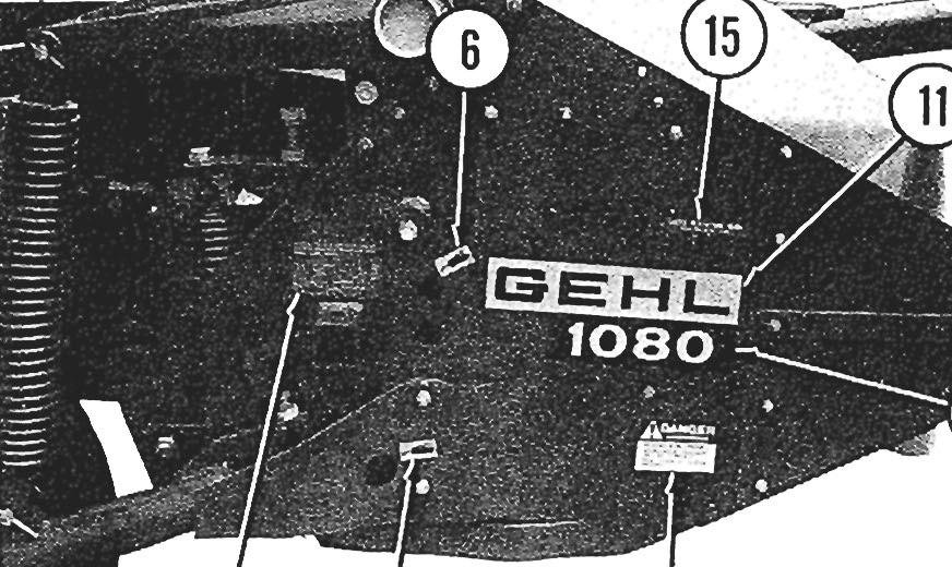
42 DECAL LOCATONS Decal Locations are shown to assist in a pplicat ion of new decals in the event of damage to the Decal or refinishing of the machine. Check listing for information and the illustrations for their location. Surfaces MUST be free from dirt. dust. grease and other foreign material before applying the new Decal. To apply, remove the smaller portion of the decal backing paper and apply this part of the exposed adhesive backing to the clean surface while maintaining proper position and alignment. Peel the other portion of the backing paper off slowly while applying hand pressure to smooth out Decal surface. NOTE: Discard Decals NOT required for this machine. Always order Decals by set number. DO NOT order Decals separately. A WARNNG: Always Observe Safety Rules Shown on Decals. f Decals become damaged, or if unit is repainted, replace Decals. The Decal Set Numberfor the DC080 Disc Conditioner is The Set includes the following: CAUTON - PTO Shield & Lock Chain Attachment Decal - Hitch Clip Setup CAUTON Operation Only CAUTON - General Safety CAUTON - Read Operator's Manual Decal - Grease Fitting Symbol (3 Places) WARNNG - nstall Transport Pin Decal - Grease Two Fittings Regularly GEHL 5 x 24-1/2 (2 Places) x 15-1/ GEHL 3 x /16 x 10-1/ DANGER - Rotating Blades (4 Places) Decal - Cutterbar Oil Level Checking Detail Decal - Check Flotation Here CAUTON - Stay Clear of Cutterbar (2 Places) 42


43 43
44 DC NUMERCAL NDEX Part Page Part Page Part Page Part Page ,3 J, , , , ,26,31, , , ,25,26, , , ,29,37, , , , , , , , " J , , , " " , " , , " , , , , , , , , , ,
45 DC NUMERCAL NDEX Part Page Part Page Part Page Part Page , , , , , ' , , , , , , , '" , ,32, , ,38, ,... 26,38, , , , , '" , ,35, ,25, , , '" , ,33, ,25 45
46 46 NOTES
47 NDEX Page c Check Lists o Decal Location G General nformation General Bolt Torque Data...9 Preparing Tractor...9 Mounting to the Tractor Transport Position Wheel Pressure & Drawbar Positions... Ground Press ure Mowing Rubber Conditioner Rollers Swathdoors Knife Changing Oil Level Filling Plugs & Oil Contents Draining & Filling Bolt & Hardware Check Toolbox Supplies...20 Slip Clutch Service...20 Lu brication ntroduction...3 N Numerical ndex Page s Safety...8 Service Parts Drawbar, Drive Shaft & Jack Main Frame, Wheels & Windrowers Lift System...26 Hydraulic Cylinder....,...27 Transmission & Mid-section Drive...28 Roller Drives...29 Cutterbar Drive...30 Gearbox, Cutterbar Skid & Stone Protectors Cutterbar & Gears...32 Cutterbar Attachment...33 Cutterbar & Discs...34 Telescoping PTO & Shields (Used after Serial #2334)...35 Telescoping PTO & Shields (Used before Serial #2335) Lower Roller...37 Right Roller Support...38 Upper Roller & Left Roller Support Specifications...4 T Table of Contents...3 W Warranty... nside Front Cover


48 ., ~~ ", ::~. _~_ > :.,':J, ~ _:. _ s...;~~...:: '_ ~ '. - -",' ->. ;,,'- - ~~ : - '''' - c ~' '" - _ ~.' -. ~.. _f '- f '1--,. _ -," ~"':Lo~_----;./"...,, _ -.. _-,-,~: ~- -':~..' ".: ~ -"- - ~ ~ '. '_.: -, ' FARM EQUPMENT GEHL COMPANY WEST BEND, WSCONSN U.S.A /1.5M1 P282 Printed n U.S.A.
Form No Replaces. Finger Wheel Rake OPERATOR'S AND SERVICE PARTS MANUAL
 Form No. 903031 Replaces 902521 Finger Wheel Rake OPERATOR'S AND SERVICE PARTS MANUAL GEHL COMPANY New Agricultural Equipment Gehl Company (Incorporated), hereinafter referred to as GEHL, as manufacturer
R T SERIES ROTARY TILLER
 R T SERIES ROTARY TILLER Operating and Maintenance Manual TABLE OF CONTENTS 1. PRODUCT WARRANTY. 3 2. CHECKLIST Dealer s File Copy. 4 Customer s File Copy.. 5 3. INTRODUCTION 6 4. SPECIFICATIONS.. 7 5.
TABLE OF CONTENTS DESCRIPTION. Safety Instructions & Safety Sign Locations Operating Instructions Assembly Instructions...
 TABLE OF CONTENTS DESCRIPTION PAGE Warranty... 1 Safety Instructions & Safety Sign Locations... 2 Operating Instructions... 3 Assembly Instructions... 5 500 & 600 Snowblower Drawings... 8 500 & 600 Snowblower
WARRANTY REGISTRATION AND POLICY
 WARRANTY REGISTRATION AND POLICY Buhler Manufacturing products are warranted for a period of twelve (12) months from original date of purchase, by original purchaser, to be free from defects in material
Form No Finger Wheel Rake OPERATOR'S AND SERVICE PARTS MANUAL
 Form No. 903681. Finger Wheel Rake OPERATOR'S AND SERVCE PARTS MANUAL GEHL COMPANY New Agricultural Equipment Gehl Company (ncorporated), hereinafter referred to as GEHL, as manufacturer of quality machinery
Impeller Disc Mower Conditioner
 252 Form No. 90987 Revision B Impeller Disc Mower Conditioner OPERATOR S MANUAL GEHL NEW AGRICULTURAL EQUIPMENT IMPELLER DISC MOWER CONDITIONER WARRANTY GEHL AGRICULTURE DIVISION of the GEHL COMPANY, hereinafter
HAMMER KNIFE FLAIL MOWER SHREDDER
 HAMMER KNIFE FLAIL MOWER SHREDDER Operation, Service, & Parts Manual For Models: GOL79 & GOL89 October 2010 FORM: GOLShredder.QXD TABLE OF CONTENTS Installation....................................................1
TABLE OF CONTENTS. 2. CHECKLIST Dealer s File Copy. 4 Customer s File Copy INTRODUCTION SPECIFICATIONS... 7
 TABLE OF CONTENTS 1. PRODUCT WARRANTY. 3 2. CHECKLIST Dealer s File Copy. 4 Customer s File Copy... 5 3. INTRODUCTION. 6 4. SPECIFICATIONS... 7 5. SAFETY. 8-9 5.1 Mandatory Safety Shutdown Procedure. 9-11
Extreme Duty Grapple (Rock, Skeleton, Scrap & Tine) Operation and Maintenance Manual
 Operation and Maintenance Manual") Extreme Duty Grapple (Rock, Skeleton, Scrap & Tine) Operation and Maintenance Manual Revision Date: May 12, 2017 Skid Pro PO Box 982 Alexandria, MN 56308 Toll Free: 877-378-4642 www.skidpro.com TABLE OF
Extreme Duty Grapple (Rock, Skeleton, Scrap & Tine) Operation and Maintenance Manual Revision Date: May 12, 2017 Skid Pro PO Box 982 Alexandria, MN 56308 Toll Free: 877-378-4642 www.skidpro.com TABLE OF
HT /243 REPLACES. Tedder. OPERATOR'S AND SERVICE PARTS MANUAL l!i
 HT 24 242/243 904328 REPLACES 90434 Tedder OPERATOR'S AND SERVICE PARTS MANUAL l!i G E H I...: COMPANY New Agricultural Equipment G E H I...: Company (Inc.), hereinafter referred to as G E H...:, warrants
FLAIL MOWER SHREDDER
 FLAIL MOWER SHREDDER Operation, Service, & Parts Manual For Models: GML41, 49, 61, 69, & 79 February 2006 FORM: GMLMower.QXD TABLE OF CONTENTS Installation....................................................1
610 BUSHEL MANURE SPREADER
 610 BUSHEL MANURE SPREADER RODA MANUFACTURING 1008 LOCUST ST. HULL, IA. 51239 Art s-way Manufacturing 712-439-2366 Co., Inc. Hwy 9 West - PO Box 288 WWW.RODAMFG.COM Armstrong, IA. 50514 U.S.A 2 INTRODUCTION
Precision Reel Mowers OPERATOR S MANUAL
 Precision Reel Mowers OPERATOR S MANUAL Models RL205 / RL207 RL255 / RL257 / RL2510 Introduction Read this information carefully to learn how to operate and maintain your product properly and to avoid
Model 35 PARTS MANUAL
 Model 35 PARTS MANUAL Version 3-2007 Ashland Industries Inc. 1115 Rail Drive P.O. Box 717 Ashland, WI. 54806 Ph: 877-634-4622 Toll Free Ph: 715-682-4622 Fx: 715-682-9717 www.ashlandind.com Model 35 Scraper
ROTARY TILLER. Operation, Service & Parts Manual For "AS" Series. FORM: ASTillerBook.QXD
 ROTARY TILLER Operation, Service & Parts Manual For "AS" Series FORM: ASTillerBook.QXD April 2002 TABLE OF CONTENTS Preparation......................................1 Assembly Instructions.............................2
Wheel Horse. 36 Tiller. Model No & Up. Operator s Manual
 FORM NO. 8 9 Rev. A Wheel Horse 6 Tiller for Classic Garden Tractors Model No. 7970 690000 & Up Operator s Manual IMPORTANT: Read this manual carefully. It contains information about your safety and the
G E H l..; L: COMPANY New Agricultural Equipment
 G E H l..; L: COMPANY New Agricultural Equipment G E H l..; L: Company (Inc.), hereinafter referred to asg as G E H l..;, L:, warrants new G E H l..; L: machinery and attachments (the "Equipment") to be
OPERATOR and PARTS MANUAL GRAIN GRINDER MODEL GG 10
 1 Serial # GG10-AUG10-6-0701 to GG10-AUG10-276-0314 ROTO GRIND OPERATOR and PARTS MANUAL GRAIN GRINDER MODEL GG 10 ROTO GRIND BURROWS ENTERPRISES, INC. 2024 East 8 th Street Greeley, Colorado 80631 970-353-3769
SECTION V ASSEMBLY CAUTION THE FOLLOWING SAFETY PRECAUTIONS SHOULD BE THOROUGHLY UNDERSTOOD BEFORE ATTEMPTING MACHINE ASSEMBLY.
 SECTION V ASSEMBLY CAUTION THE FOLLOWING SAFETY PRECAUTIONS SHOULD BE THOROUGHLY UNDERSTOOD BEFORE ATTEMPTING MACHINE ASSEMBLY. 1. Wear personal protective equipment such as, but not limited to protection
ROTARY RAKE OPERATOR'S MANUAL
 MODEL 1150 ROTARY RAKE OPERATOR'S MANUAL DO NOT OPERATE THIS EQUIPMENT UNTIL THIS MANUAL HAS BEEN READ AND UNDERSTOOD. Part Number: 17.00801C May 2005 Miller-St. Nazianz, Inc. P.O. Box 127 St. Nazianz,
OPERATO 'S AND SERVICE PARTS MANUAL
 Form No. 903468 Replaces 903033 V-Rakes ~ ~ [Q1 ~,~~,t~1"'\w\~ lil.i~ @. I ~ WR308 ((. OPERATO 'S AND SERVICE PARTS MANUAL GEHL COMPANY New Agricultural Equipment Gehl Company (incorporated), hereinafter
LEWIS WINDROWER OWNER / OPERATOR MANUAL
 LEWIS WINDROWER OWNER / OPERATOR MANUAL MODEL # WR-1 WINDROWER Manufactured by: LEWIS BROTHERS MANUFACTURING, INC. Post Office Box 146 Baxley, GA 31513 Tel: (912) 367-4651 Fax: (912) 367-3958 2-21-14 1
Model 858-RH. Operating and Assembly Manual. Palmor Products Inc Serum Plant Road Thorntown, IN 46071
 Model 5-RH Operating and Assembly Manual Palmor Products Inc. 55 Serum Plant Road Thorntown, IN 6071 3/31/015 SAFETY RULES Remember, any power equipment can cause injury if operated improperly or if the
Operating and Assembly Manual
 Model 1080 Operating and Assembly Manual Midwest Equipment Manufacturing, Inc. 5225 Serum Plant Road Thorntown, IN 46071 08-02-16 SAFETY RULES Remember, any power equipment can cause injury if operated
OPERATOR and PARTS MANUAL GRAIN GRINDER MODEL GG 7
 1 Serial # GG7-AUG10-71-1013 and Higher 2014 and up ROTO GRIND OPERATOR and PARTS MANUAL GRAIN GRINDER MODEL GG 7 ROTO GRIND BURROWS ENTERPRISES LLC 2024 East 8 th Street Greeley, Colorado 80631 970-353-3769
HR930 Rotary Rake. Illustrated Parts Breakdown. Tongue & Main Frame. Gearbox & Tine Arm
 HR0 Rotary Rake Illustrated Parts Breakdown Page Page Page Page Page Page Tongue & Main Frame Guards Gearbox & Tine Arm Axle Assembly Rotary Gearbox PTO Shaft 0//0 Tongue & Main Frame 0 0 0 0 Ref# Description
FORAGE BOX MODEL 5300 REAR UNLOAD OPERATOR'S MANUAL DO NOT OPERATE THIS EQUIPMENT UNTIL THIS MANUAL HAS BEEN READ AND UNDERSTOOD.
 FORAGE BOX MODEL 5300 REAR UNLOAD OPERATOR'S MANUAL DO NOT OPERATE THIS EQUIPMENT UNTIL THIS MANUAL HAS BEEN READ AND UNDERSTOOD. Miller-St. Nazianz, Inc. Art s-way Manufacturing Co., Inc. P.O. Box 127
Wood Chipper Model C550M Operator's Manual
 Wood Chipper Model C550M Operator's Manual THIS MANUAL MUST BE READ AND UNDERSTOOD BEFORE ANYONE OPERATES THIS MACHINE! Manual# 990023 Revised 01/2010 YOU MUST FILL OUT YOUR WARRANTY REGISTRATION TO ACTIVATE
TABLE OF CONTENTS. Warranty Disclaimers Delivery Checklist After Sale Checklist Safety Set Up... 8
 TABLE OF CONTENTS Pickett Equipment Warranty... 2 Warranty Disclaimers... 3 Delivery Checklist... 4 After Sale Checklist... 4 Safety... 5-7 Set Up... 8 Machine Adjustments and Operation... 9 Maintenance
Operator's Manual. VC-60 & VC-60 Plus Harper Industries, Inc. 7/03 Part No
 Operator's Manual VC-60 & VC-60 Plus 2003 Harper Industries, Inc. 7/03 Part No. 970066 Thank you for purchasing a Harper/Goossen Verti-Cutter. As with all Harper/Goossen products, the Harper/Goossen Verti-Cutter
OPE R AT O R S MANU A L QUICK-HITCH ADAPTER. 5BP (Field conversion kit)
") OPE R AT O R S MANU A L 5BP006750 (Field conversion kit) Manual 5BP97378B Date 06/8/05 SAFETY Take note! This safety alert symbol found throughout this manual is used to call your attention to instructions
OPE R AT O R S MANU A L 5BP006750 (Field conversion kit) Manual 5BP97378B Date 06/8/05 SAFETY Take note! This safety alert symbol found throughout this manual is used to call your attention to instructions
Operating and Assembly Manual
 Model CV385-PRO Operating and Assembly Manual Midwest Equipment Manufacturing, Inc. 5225 Serum Plant Road Thorntown, IN 46071 2-09-16 SAFETY RULES Remember, any power equipment can cause injury if operated
Operator s/parts Manual
 Operator s/parts Manual 3-Point Solid Stand Drills Pull Hitch Package Manufacturing, Inc. P.O. Box 5060 Salina, Kansas 67402-5060! Read the operator s manual entirely. When you see this symbol, the subsequent
Planting Components. Operator s/parts Manual
 Operator s/parts Manual Unit Mount Conservation Coulter and Spring Package Attachment for JD 7000, JD 7200, White 6100, Kinze Planters and Great Plains Row Units Planting Components! Read the operator
Planting Components. Operator s/parts Manual Terra-Tine. Row Cleaner
 Operator s/parts Manual Terra-Tine Row Cleaner Planting Components! Read the operator s manual entirely. When you see this symbol, the subsequent instructions and warnings are serious - follow without
Operator s Manual. Table of Contents. Rotary Cutter RC35120 RCM Copyright 2008 Printed M 7/14/08
 Operator s Manual RC35120 RCM35120 Rotary Cutter 10438 Cover photo may show optional equipment not supplied with standard unit.! Read the Operator s manual entirely. When you see this symbol, the subsequent
Z Master. 62 Mower. for Z Master Z 255 Traction Unit. Model No & UP. Operator s Manual
 FORM NO. 9 88 Z Master 6 Mower for Z Master Z 55 Traction Unit Model No. 7408 89000 & UP Operator s Manual IMPORTANT: Read this manual carefully. It contains information about your safety and the safety
ROTARY MOWER OPERATION, SERVICE & PARTS MANUAL FOR
 ROTARY MOWER OPERATION, SERVICE & PARTS MANUAL FOR L-G-40-40-P, L-G-48-40-P, L-G-60-40-P & L-G-72-40-P Slip Clutch Models: L-G-60-40-SC-P & L-G-72-40-SC-P February 2003 FORM: RotMwrBook.QXD TABLE OF CONTENTS
MK AUGERS POWER SWING KIT ASSEMBLY & OPERATION MANUAL
 MK AUGERS POWER SWING KIT ASSEMBLY & OPERATION MANUAL Read this manual before using product. Failure to follow instructions and safety precautions can result in serious injury, death, or property damage.
HR24TS Rotary Rake. Serial Numbers and higher. Illustrated Parts Breakdown. Guards and Guard Arm, Front Hay Curtain Mount.
 HRTS Rotary Rake Serial Numbers 00 and higher Illustrated Parts Breakdown Page Page Page Page Page Page Page Page Page Page 0 Page Page Page Page Page Page Page Page Page Page 0 Tongue Front Frame Guards
WARRANTY REGISTRATION AND POLICY
 WARRANTY REGISTRATION AND POLICY Buhler Manufacturing products are warranted for a period of twelve (12) months from original date of purchase, by original purchaser, to be free from defects in material
ATV TRACK KIT. Operator s Manual Installation Instructions Service Instructions Replacement Parts List. Effective Date: October, 2012
 p/n 2258-642 ATV TRACK KIT Operator s Manual Installation Instructions Service Instructions Replacement Parts List Track Assembly Kits (p/n 1436-204) Mounting Assembly Kits (p/n 1436-205) 1436-815) Effective
Precision Reel Mowers OPERATOR S MANUAL
 Precision Reel Mowers OPERATOR S MANUAL Models RL205H / RL207H RL205HC / RL207HC Evergreen Turf Equipment, LLC 1028 4 th St. SW, Bldg. A Auburn, Washington 98001 caltrimmer.com Introduction Read this information
TO THE OWNER ASSEMBLY
 TO THE OWNER This is an operational and general maintenance manual only and does not cover repair. All repair work must be performed by an authorized BOLENS DEALER or the factory warranty is void. Bolens
OPERATOR S MANUAL FABRIC 3-BAG GRASS CATCHER PART NO PRINTED 8/2012 PRINTED IN USA
 OPERATOR S MANUAL FABRIC -BAG GRASS CATCHER Models: GC-STC-V This manual contains the operating instructions and safety information for your Scag mower accessory. Reading this manual can provide you with
Wheel Horse. 52 Mowers. Model No & Up Model No & Up. Operator s Manual
 FORM NO. 9-567 Wheel Horse 5 Mowers for Lawn & Garden Tractors Model No. 7880 890000 & Up Model No. 7885 890000 & Up Operator s Manual IMPORTANT: Read this manual carefully. It contains information about
WOOD CHIPPER WC1103 5PQ (8/02/12)
") O P E R A T O R ' S M A N U A L WOOD CHIPPER WC1103 5PQ990101 (8/02/12) To the Owner; Thank-You for choosing a quality product from Frontier Equipment. We strive to give you the best equipment and the
O P E R A T O R ' S M A N U A L WOOD CHIPPER WC1103 5PQ990101 (8/02/12) To the Owner; Thank-You for choosing a quality product from Frontier Equipment. We strive to give you the best equipment and the
Operation and Parts Manual
 Operation and Parts Manual 3-Point PTO and Hydraulic Stump Grinders Models: SC-25 and SC-25H SC-50 and SC-50H Safety Operation Maintenance Repair Troubleshooting Parts Parts SC-50 and SC-50-H Stumpbuster
Planting Components. Operator s/parts Manual. Row Cleaner VIII. Terra-Tine
 Operator s/parts Manual Terra-Tine Row Cleaner VIII Planting Components! Read the operator s manual entirely. When you see this symbol, the subsequent instructions and warnings are serious - follow without
SHEYENNE TELE-BOOM OWNERS MANUAL OPERATOR INSTRUCTIONS PARTS BOOK
 SHEYENNE TELE-BOOM OWNERS MANUAL OPERATOR INSTRUCTIONS PARTS BOOK 701 Lenham Ave. SW PO Box 647 Cooperstown ND 58425 1-800-797-1883 701-797-2700 * 701-797-2584 Fax www.sheyennemfg.com TABLE OF CONTENTS
Operator s Manual. Go Galvanized! YOU'RE ALWAYS AHEAD...WITH A MODERN BEHIND.
 SUMMER 2008 C2 tilting grader blade Operator s Manual YOU'RE ALWAYS AHEAD...WITH A MODERN BEHIND. 003-5336 003-5342 003-5531 003-5544 P.O. Box 790 Beaumont, Tx 77704 409.833.2665 1.800.231.8198 Fax: 409.726.8333
Sidewalk-Pro SP-50 Sidewalk-Pro SP-65
 O M D Sidewalk-Pro SP-50 Sidewalk-Pro SP-65 Trynex International 200 (REV 000) Table of Contents INTRODUCTION..............................................................................................
tRIPr Chief Grain Cart. Operator s Manual. Operator s Manual
 125-000-01 125-000-01 1tRIPr 1tRIPr Operator s Manual 1210 Chief Grain Cart Operator s Manual Operator s Manual TO THE DEALER Predelivery/Delivery Checklist 1210 Grain Cart PREDELIVERY/DELIVERY CHECKLIST
Mulching and Finishing Mowers MP and FP
 Mulching and Finishing Mowers MP and FP Parts Manual Locke Turf 0 Highway E, Opp, Alabama, () -00 Transport Wheel, Tire & Spindle MP and FP ALPHABETICAL INDEX CONTENTS PAGE 00 Hydraulic Cylinder (Rear)
Two-Stage Snow Blower For 4WD Pick Up Trucks. Operator s Manual
 Two-Stage Snow Blower For 4WD Pick Up Trucks Operator s Manual Distrubuted by: Metal Fabricating LLC P.O. Box 831 Brodheadsville, PA 18322 Phone: 570-992-9989 SnowVac.com WARRANTY POLICY Metal Fabricating
25 BUSHEL MANURE SPREADER
 25 BUSHEL MANURE SPREADER RODA MANUFACTURING 338 MAIN ST. HULL, IA. 51239 Art s-way Manufacturing 712-439-2366 Co., Inc. Hwy 9 West - PO Box 288 WWW.RODAMFG.COM Armstrong, IA. 50514 U.S.A 2 INTRODUCTION
RED23305 Owner s Manual
 RED23305 Owner s Manual 5 foot, 3-Point Mounted Snow Blower 270 West Park Avenue Huron, SD 57350 866-526-5682 Serial Number: Date of Purchase: Red Devil Snow Blower See Figure 1. 1. The Red Devil Snow
SPINNER SPREADER. Operation, Service & Parts Manual For Models S203L, S273L & S503L. May Form: Spnsprdr.PM65
 SPINNER SPREADER Operation, Service & Parts Manual For Models S20L, S27L & S0L May 200 Form: Spnsprdr.PM TABLE OF CONTENTS Welcome/Introduction... 1 Training... 1 PreOperation... 1 Spreader Assembly...2
ProLine. 44 Mower. for 120 Traction Unit. Model No & Up. Operator s Manual
 FORM NO. 9 ProLine Mower for 0 Traction Unit Model No. 05 99000 & Up Operator s Manual IMPORTANT: Read this manual carefully. It contains information about your safety and the safety of others. Also become
Predelivery Instructions
 PINK Predelivery Instructions SR5030 Split-Row Planter Manufacturing, Inc. P.O. Box 5060 Salina, Kansas 67402-5060! Read this manual entirely. When you see this symbol, the subsequent instructions and
p.t.o. Slip clutch Read this material before using this product. Failure to do so can result in serious injury. Save this manual.
 p.t.o. Slip clutch 65517 Installation Instructions Distributed exclusively by Harbor Freight Tools. 3491 Mission Oaks Blvd., Camarillo, CA 93011 Visit our website at: http://www.harborfreight.com Read
CRUSTBUSTER OWNER / OPERATOR MANUAL
 CRUSTBUSTER OWNER / OPERATOR MANUAL MODEL # CB-1 CRUSTBUSTER Manufactured by: LEWIS BROTHERS MANUFACTURING, INC. Post Office Box 146 Baxley, GA 31513 Tel: (912) 367-4651 Fax: (912) 367-3958 5-2-17 1 INTRODUCTION
HAMMER KNIFE FLAIL MOWER SHREDDER
 HAMMER KNIFE FLAIL MOWER SHREDDER Operation, Service, & Parts Manual For Models: GOF69, 79, 89, 98, & 108 February 2006 Rev. 2009 FORM: GOFMower.QXD TABLE OF CONTENTS Installation....................................................1
ROTARY TILLER. Operation, Service & Parts Manual For P-P/C Series. November 1996 (Rev. 4-05) FORM: PTillerBook.QXD
 FORM: PTillerBook.QXD") ROTARY TILLER Operation, Service & Parts Manual For P-P/C Series FORM: PTillerBook.QXD November 1996 (Rev. 4-05) TABLE OF CONTENTS Preparation......................................1 Assembly Instructions.............................2
ROTARY TILLER Operation, Service & Parts Manual For P-P/C Series FORM: PTillerBook.QXD November 1996 (Rev. 4-05) TABLE OF CONTENTS Preparation......................................1 Assembly Instructions.............................2
Update Manual. Manufacturing, Inc. 7 & 10 End Wheel No-Till Clutch Linkage. P.O. Box 218 Assaria, Kansas Effective 5/3/ M
 Update Manual 7 & 10 End Wheel No-Till Clutch Linkage Manufacturing, Inc. P.O. Box 218 Assaria, Kansas 67416 Effective 5/3/96 152-156M General Information General Information Important Notice Great Plains
Wheel Horse. 42 Mower. for Lawn and Garden Tractors. Model No & Up. Operator s Manual
 FORM NO. 9 559 Rev A Wheel Horse 4 Mower for Lawn and Garden Tractors Model No. 78 890000 & Up Operator s Manual IMPORTANT: Read this manual carefully. It contains information about your safety and the
Operating and Assembly Manual
 Model 380/385-IC/385-LH Operating and Assembly Manual Midwest Equipment Manufacturing, Inc. 5225 Serum Plant Road Thorntown, IN 46071 2-0916 SAFETY RULES Remember, any power equipment can cause injury
480T All-Wheel-Steer. Loader
 480T All-Wheel-Steer Form No. 918119 Revision C Loader Beginning Serial Number: 342100107 PARTS MANUAL Introduction When ordering service parts, specify the correct part number, full description, quantity
OWNER S MANUAL 40 LAWN AERATOR SAT-40 BH. Assembly Installation Operation Repair Parts. Visit us on the web! MODEL:
 OWNER S MANUAL 40 LAWN AERATOR MODEL: SAT-40 BH Assembly Installation Operation Repair Parts For the latest product updates & setup tips: Visit us on the web! www.brinly.com Important: This manual contains
4750 Drill. Repair Parts
 4750 Drill Repair Parts #615997-2016 Identification Your CrustBuster drill is identified by a Serial Number and Model Number. Record these numbers in the spaces provided in this manual and refer to them
Commercial Pro Plow Combo, 50" ATV
 CHANGING YOUR LANDSCAPE SINCE 1945 swisherinc.com OWNER S MANUAL 19975 Starting Serial #: L215-001001 Commercial Pro Plow Combo, 50" ATV IMPORTANT Read and follow all Safety Precautions and Instructions
48 Side Discharge Mower
 FORM NO. 9 650 Rev A Wheel Horse 8 Side Discharge Mower for Classic Garden Tractor Model No. 786 890000 & Up Operator s Manual IMPORTANT: Read this manual carefully. It contains information about your
GROUNDSMASTER. 52 Recycler. for 120 Traction Unit. Model No & UP. Operator s Manual
 FORM NO. 8-980 Rev A GROUNDSMASTER 5 Recycler for 0 Traction Unit Model No. 077 79000 & UP Operator s Manual IMPORTANT: Read this manual carefully. It contains information about your safety and the safety
36 Tiller Wheel Horse Lawn and Garden Tractor Attachment
 Form No. 9 6 Rev B 6 Tiller Wheel Horse Lawn and Garden Tractor Attachment Model No. 797 890000 and Up Operator s Manual English(En) Contents Page Introduction................................ Safety.....................................
MODEL G300 BRAKE BLEEDER
 MODEL G300 BRAKE BLEEDER Installation, Operation & Repair Parts Information Branick Industries, Inc. 4245 Main Avenue P.O. Box 1937 Fargo, North Dakota 58103 REV120716 P/N: 81-0035H THIS PAGE INTENTIONALLY
Operating and Assembly Manual
 Model CV385-PRO Operating and Assembly Manual Palmor Products Inc. 5225 Serum Plant Road Thorntown, IN 46071 11-6-07 Model CV385-PRO Trac-Vac Parts List Key Part No. Description Qty. 1 38010 Engine Frame,
Rotary Mowers. Instruction Book
 Instruction Book Rotary Mowers Manufactured By: Helm Welding (1983) Limited 86386 Lucknow Line PO Box 158 Lucknow, Ontario, Canada NOG 2HO TEL: (519) 529-7627 or 529-7000 FAX: (519) 529-3260 Email: inquiry@lucknowproducts.com
BALE KING GT40 Grain Feeder Operator's & Parts Manual Last Update: November 20, 2014 Bridgeview Manufacturing Inc - 1 -
 BALE KING GT40 Grain Feeder Operator's & Parts Manual Last Update: November 20, 2014 Bridgeview Manufacturing Inc - 1 - Your Authorized Dealer: Your Serial Number: The Serial Number is located on the tank.
DM-135 DRUM MOWER USER S MANUAL
 DM-135 DRUM MOWER USER S MANUAL 1 DM135 DRUM MOWER INSTRUCTIONS CHAPTER 1 SAFE OPERATION Do not attempt to operate the mower until you have read the operator s manual and all the safety signs on the mower.
Operating and Assembly Manual
 Model 455-IC/PRO/H Operating and Assembly Manual Midwest Equipment Manufacturing, Inc. 5225 Serum Plant Road Thorntown, IN 46071 03-08-12 SAFETY RULES Remember, any power equipment can cause injury if
PARTSBOOK. This part of the manual contains part numbers and illustrations based on the latest information available at the time of print.
 2 PARTSBOOK This part of the manual contains part numbers and illustrations based on the latest information available at the time of print. Hall Manufacturing, Inc. reserves the right to make changes at
GRADING SCRAPERS INDUSTRIAL SERIES OPERATION, SERVICE & PARTS MANUAL FOR MODELS: GSI7-SS, GSI7, GSI8, GSI10, & GSI12.
 GRADING SCRAPERS INDUSTRIAL SERIES OPERATION, SERVICE & PARTS MANUAL FOR MODELS: GSI7-SS, GSI7, GSI8, GSI10, & GSI12 September 2006 FORM: IndGradingScrpr.QXD TABLE OF CONTENTS Safety Information......................1-2
Operating and Assembly Manual
 Model 470-/H/PRO/IC Operating and Assembly Manual Midwest Equipment Manufacturing, Inc. 5225 Serum Plant Road Thorntown, IN 46071 11-11-11 SAFETY RULES Remember, any power equipment can cause injury if
Finishing Mower Estate 72
 Finishing Mower Estate 72 Owners/Operators Manual & Spare Parts List Issue Date: October 2011 1 Introduction Your FIELDMASTER Estate 72 Finishing Mower has been designed to do a range of work to your satisfaction.
36 Rear Discharge Mower
 FORM NO. 8 95 Rev. A Wheel Horse 6 Rear Discharge Mower for Classic Garden Tractor Model No. 7805 790000 & Up Operator s Manual IMPORTANT: Read this manual carefully. It contains information about your
MAXILATOR OPERATOR'S MANUAL INLINE MOWER CADDY MODEL MBS RICE ROAD ROCKMART, GA (866) HAYBALE
 HAYBALE") MAXILATOR OPERATOR'S MANUAL INLINE MOWER CADDY MODEL MBS-80 51 RICE ROAD ROCKMART, GA 30153 (866) HAYBALE MAXILATOR EQUIPMENT, LLC Phone: (866) HAYBALE LIMITED WARRANTY Effective January 1, 2016 Maxilator
MAXILATOR OPERATOR'S MANUAL INLINE MOWER CADDY MODEL MBS-80 51 RICE ROAD ROCKMART, GA 30153 (866) HAYBALE MAXILATOR EQUIPMENT, LLC Phone: (866) HAYBALE LIMITED WARRANTY Effective January 1, 2016 Maxilator
B-BP-4 BALLPARK 4 GROOMER
 B-BP-4 BALLPARK 4 GROOMER TABLE OF CONTENTS 01 Ballpark 4 Cover Page 02 Table of Contents 03 Warranty 04 General Information & Tool Functions 05 Tool Adjustments & Basic Maintenance 06 How to Use the Ballpark
Operating and Assembly Manual
 Model 455-IC/PRO/H Operating and Assembly Manual Palmor Products Inc. 5225 Serum Plant Road Thorntown, IN 46071 03-08-12 SAFETY RULES Remember, any power equipment can cause injury if operated improperly
STOP. 44" High Speed Sweeper. Operator's Manual. Model No Safety Assembly Operation Maintenance Parts
 Operator's Manual STOP 44" High Speed Sweeper Model No. 486.029 DO NOT RETURN TO STORE For Missing Parts or Assembly Questions Call 1-866-576-8388 CAUTION: Before using this product, read this manual and
Model 452-DIC/DH. Operating and Assembly Manual
 . Model 452-DIC/DH Operating and Assembly Manual Palmor Products Inc. 5225 Serum Plant Road Thorntown, IN 46071 02-14-12 SAFETY RULES Remember, any power equipment can cause injury if operated improperly
Warnings and Precautions FAILURE TO READ, UNDERSTAND AND FOLLOW THESE INSTRUCTIONS MAY LEAD TO SERIOUS INJURY OR DEATH!
 Instruction Booklet 2006 Summit ATV Pak-Mule Single Axle 84000 Summit ATV Pak-Mule Tandem Axle 84002!! READ ME FIRST!!! Please read carefully BEFORE using you new Summit ATV Product. Congratulations! You
WOOD CHIPPER WC1105 5PQ (8/08/2012)
") O P E R A T O R ' S M A N U A L WOOD CHIPPER WC1105 5PQ990102 (8/08/2012) To the Owner; Thank-You for choosing a quality product from Frontier Equipment. We strive to give you the best equipment and the
O P E R A T O R ' S M A N U A L WOOD CHIPPER WC1105 5PQ990102 (8/08/2012) To the Owner; Thank-You for choosing a quality product from Frontier Equipment. We strive to give you the best equipment and the
Wheel Horse. 44 Snowthrower. for 5xi Lawn and Garden Tractors. Model No & Up. Operator s Manual
 FORM NO. 8 Rev A Wheel Horse Snowthrower for 5xi Lawn and Garden Tractors Model No. 7966 890050 & Up Operator s Manual IMPORTANT: Read this manual, and your tractor manual, carefully. They contain information
IMPORTANT READ ME FIRST
 IMPORTANT READ ME FIRST Thank you for purchasing your Kushlan Mixer. We hope that you will enjoy using it for many years to come. SHOULD YOU REQUIRE ANY SET-UP OR OPERATING ASSISTANCE WITH YOUR PRODUCT,
Operator s Manual. Twin Rear Bagger For FastAttach Compatible Lawn Tractors
 Operator s Manual Twin Rear Bagger For FastAttach Compatible Lawn Tractors Models OEM-190-601 (for 38-inch & 42-inch decks) OEM-190-602 (for 46-inch decks) MTD PRODUCTS INC. P.O. BOX 368022 CLEVELAND,
MODEL L/R/EF Sectional Tire Spreader
 MODEL L/R/EF Sectional Tire Spreader Installation, Operation & Repair Parts Information Branick Industries, Inc. 4245 Main Avenue P.O. Box 1937 Fargo, North Dakota 58103 REV08032016 P/N: 81-0195E TABLE
MOBILE 4 AUGER MIXER OWNER S MANUAL
 MOBILE 4 AUGER MIXER OWNER S MANUAL Transcanadian Highway, Exit 170 230 Industriel Blvd, St-Germain Quebec, Canada J0C-1K0 Tel.: (819)395-4282 Fax : (819)395-2030 www.valmetal.com 1997/06 info@valmetal.com
Finishing Mower TABLE OF CONTENTS
 TABLE OF CONTENTS DESCRIPTION PAGE NUMBER Warranty 1 Operating Safety 2 Transport Safety 3 Maintenance Safety 3 Safety Signs 4 Hitch Assembly Instructions 5 Operating Instructions 6 Field Use Preparation
1 RS-300/D 320/D 340/D 350H Parts Manual
 300/D 320/D 340/D 350H Parts Manual Table Of Contents Three Point Hitch / Hitch Frame Assembly... 3 Tongue Pull Hitch Assembly... 7 Main Gearbox... 11 Crank Handle & Gear... 13 Hydraulic Lift... 15 Rotor
MODEL 565CKG Operating and Assembly Manual Midwest Equipment Manufacturing, Inc Serum Plant Road Thorntown, IN 46071
 MODEL 565CKG Operating and Assembly Manual Midwest Equipment Manufacturing, Inc. 5225 Serum Plant Road Thorntown, IN 46071 11-20-14 SAFETY RULES Remember, any power equipment can cause injury if operated