ROTARY RAKE OPERATOR'S MANUAL
|
|
|
- Sheena McDaniel
- 5 years ago
- Views:
Transcription
1 MODEL 1150 ROTARY RAKE OPERATOR'S MANUAL DO NOT OPERATE THIS EQUIPMENT UNTIL THIS MANUAL HAS BEEN READ AND UNDERSTOOD. Part Number: C May 2005 Miller-St. Nazianz, Inc. P.O. Box 127 St. Nazianz, WI (920) FAX:
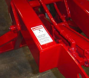
2 INTRODUCTION This Operator's Manual is provided to acquaint the operator with the safety and operation of the Miller Pro 1150 Rotary Rake. Complete Assembly, Operation, Lubrication and Maintenance procedures are provided. Following the recommended procedures will help you achieve many years of dependable service. This manual is considered part of your machine and should remain with the machine at all times. Make sure the operator reads and understands the manual before placing the rake into operation. Failure to follow the recommended procedures may result in injury and equipment damage, and could void the warranty. MACHINE SERIAL NUMBER The machine serial number is located on the side of the rake frame near the operator's manual storage tube. For your convenience refer to this number and your product model number when requiring service or parts information. Record the machine serial number, model number, date of purchase and dealership name in the space provided below. Date Purchased Model No. Serial No. Dealership Right and Left Hand sides are determined from a position standing at the rear of the rake looking toward the direction of travel. A "Right Hand Rake" discharges to the right (swath screen is on the right side). A "Left Hand Rake" discharges to the left. (Swath screen is on the left side). The Delivery and Warranty Registration Card found in the front of this manual must be completed and signed to validate your warranty protection. You must read and understand the places where you attest to having received instructions as to care, adjustments, safe operation and applicable warranty policy. The terms and conditions of the warranty are specified on the rear cover of this manual. WARNING SOME PHOTOGRAPHS USED HEREIN MAY SHOW DOORS, GUARDS AND SHIELDS OPENED OR REMOVED. BE SURE THAT ALL DOORS, GUARDS AND SHIELDS ARE FASTENED IN THEIR PROPER POSITION BEFORE MACHINE IS OPERATED! 38


3 OVER ALL MODEL VIEW Fully assembled left hand rake with PTO drive Fully assembled right hand rake with hydraulic drive. 1
4 This page intentionally left blank. 2
5 TABLE OF CONTENTS ROTARY RAKE Pre-Delivery Check List, Dealer Copy... 4 SAFETY PRECAUTIONS Power Source Shutdown Procedure... 5 SAFETY DECALS CONTROLS & SAFETY EQUIPMENT TRACTOR/RAKE PREPARATION Tractor/PTO Setup Hydraulic Drive Rake Height/Leveling Adjustment...18 Swath Screen Adjustments Cam Adjustment TRANSPORTING OPERATION Pre-operation Checklist General PTO Driven Rake Hydraulic Driven Rake LUBRICATION & MAINTENANCE Gearbox PTO Frame Tires and Wheels General Maintenance Storage ASSEMBLY OPTIONS & ACCESSORIES/SPECIFICATIONS TORQUE SPECIFICATIONS Fasteners O-Ring Fittings Flare Fittings WARRANTY... Inside Back Cover 3
6 1150 ROTARY RAKE PRE-DELIVERY CHECK LIST After the Rake has been completely set-up, the following inspections MUST be made before delivering it to the customer. Check off each item after prescribed action is taken. [] NO parts of the unit have been damaged in shipment. Check for such things as dents and loose or missing parts; correct or replace components as required. [] All bolts and fasteners are in place and tightly secured. [] As applicable, the Cylinders, Hoses and Fittings are NOT damaged, leaking or loosely connected. [] The Gearbox is filled to proper oil level; All Grease Fittings have been properly lubricated; see Lubrication chapter of this manual. [] Cam adjuster operates freely and is positioned correctly. [] Wheels are properly mounted and securely attached and Tires are properly mounted and inflated to the appropriate pressure. [] All Guards, Shields and Decals are in place and securely attached. [] Model and Serial Numbers for this unit are recorded in space provided on this page and inside the front cover. Hook the rake to the appropriate RPM tractor and test run it while checking that proper operation is exhibited by all components. Check that: [] Transport lights operate properly. [] Rotating PTO Shields turn freely. [] All Drives and Mechanisms are operating smoothly and properly adjusted. [] Hydraulic lift system operates properly. I acknowledge that pre-delivery service was performed on this unit as outlined. DELIVERY CHECK LIST The following check list is an important reminder of valuable information that MUST be passed on to the customer at the time the unit is delivered. Check off each item as you explain it to the customer. [] Give the customer their Operator s Manual. Instruct them to be sure to read and completely understand its contents BEFORE attempting to operate the unit. [] Explain the warranty. [] Direct customer on how to use the Table of Contents of this manual as a quick page number locating guide. [] Explain and review with customer the Safety information in this manual. [] Explain and review with customer the Controls and Safety Equipment chapter of this manual. [] Explain that regular lubrication and proper adjustments are required for continued proper operation and long life. Review with the customer the Lubrication and Maintenance chapters of this manual. [] Explain and review with customer the Tractor/Rake preparation and Operation sections of this manual. [] Explain and review with customer the PTO Driveline information in the separate manual provided. [] Completely fill out Owner'sRegistrations, including customer's signature, and return them to the Company. I acknowledge that above points were reviewed with me at the time of delivery. Dealership's Name Customer s Signature Dealer Representative's Name Date Checklist Filled Out Model Number Serial Number Date Delivered (Customer Copy) 4
7 1150 ROTARY RAKE PRE-DELIVERY CHECK LIST After the Rake has been completely set-up, the following inspections MUST be made before delivering it to the customer. Check off each item after prescribed action is taken. [] NO parts of the unit have been damaged in shipment. Check for such things as dents and loose or missing parts; correct or replace components as required. [] All bolts and fasteners are in place and tightly secured. [] As applicable, the Cylinders, Hoses and Fittings are NOT damaged, leaking or loosely connected. [] The Gearbox is filled to proper oil level; All Grease Fittings have been properly lubricated; see Lubrication chapter of this manual. [] Cam adjuster operates freely and is positioned correctly. [] Wheels are properly mounted and securely attached and Tires are properly mounted and inflated to the appropriate pressure. [] All Guards, Shields and Decals are in place and securely attached. [] Model and Serial Numbers for this unit are recorded in space provided on this page and inside the front cover. Hook the rake to the appropriate RPM tractor and test run it while checking that proper operation is exhibited by all components. Check that: [] Transport lights operate properly. [] Rotating PTO Shields turn freely. [] All Drives and Mechanisms are operating smoothly and properly adjusted. [] Hydraulic lift system operates properly. I acknowledge that pre-delivery service was performed on this unit as outlined. DELIVERY CHECK LIST The following check list is an important reminder of valuable information that MUST be passed on to the customer at the time the unit is delivered. Check off each item as you explain it to the customer. [] Give the customer their Operator s Manual. Instruct them to be sure to read and completely understand its contents BEFORE attempting to operate the unit. [] Explain the warranty. [] Direct customer on how to use the Table of Contents of this manual as a quick page number locating guide. [] Explain and review with customer the Safety information in this manual. [] Explain and review with customer the Controls and Safety Equipment chapter of this manual. [] Explain that regular lubrication and proper adjustments are required for continued proper operation and long life. Review with the customer the Lubrication and Maintenance chapters of this manual. [] Explain and review with customer the Tractor/Rake preparation and Operation sections of this manual. [] Explain and review with customer the PTO Driveline information in the separate manual provided. [] Completely fill out Owner'sRegistrations, including customer's signature, and return them to the Company. I acknowledge that above points were reviewed with me at the time of delivery. Dealership's Name Customer s Signature Dealer Representative's Name Date Checklist Filled Out Model Number Serial Number Date Delivered (Dealer Copy) 37
8
9 SAFETY PRECAUTIONS This symbol is used to call your attention to instructions concerning your personal safety. Be sure to observe and follow these instructions. Take time to be careful! DANGER DANGER indicates an imminently hazardous situation which, if not avoided, will result in death or serious injury. WARNING WARNING indicates a potentially hazardous situation which, if not avoided, could result in death or serious injury. CAUTION CAUTION indicates a potentially hazardous situation which, if not avoided, may result in minor or moderate injury. It may also alert against unsafe practices. BEFORE you attempt to operate this machine, read and study the following safety information. In addition, MAKE SURE that every individual who operates or works with this equipment, whether family member or employee, is familiar with these safety precautions. Miller-St. Nazianz provides guards for exposed moving parts for the operator s protection; however, some areas cannot be guarded or shielded in order to assure proper operation. The OPERATOR S MANUAL AND DECALS on the machine itself warn you of dangers and SHOULD BE READ AND OBSERVED CLOSELY. POWER SOURCE SHUTDOWN PROCEDURE Before cleaning, unclogging, adjusting, lubricating or servicing this machine: 1. Disengage the tractor PTO. 2. Deactivate tractor hydraulic controls. 3. Shut off the tractor engine, remove the starter key and take it with you. 4. Wait for all machine motion to stop. 5. Remove the telescoping PTO driveline and ALL power connections from the tractor. Failure to follow these precautions could result in death or serious injury. 5
10 SAFETY PRECAUTIONS, continued Some photographs used herein may show doors, guards and shields opened or removed. BE SURE that all doors, guards and shields are fastened in their proper position before machine is operated. Know how to stop rake operation BEFORE starting it. BE ALERT for people and/or animals in front of or around machine, when about to start machine. KEEP hands, feet and clothing away from tine arms and PTO when they are moving! DO NOT wear loose or baggy clothing when operating this unit! DO NOT allow people other than a qualified operator near the unit! DO NOT allow minors to be near the machine unless properly supervised. KEEP riders off rake. DO NOT unclog, adjust, lubricate or service your rake until you disengage the tractor PTO and shut off the tractor engine. Failure to follow this procedure may result in serious bodily injury! AVOID high pressure fluids. Escaping fluid under pressure can penetrate skin causing serious injury. DO NOT exceed a maximum towing speed of 20 MPH (32 KPH) while transporting the rake. REDUCE speed on rough or hilly ground. BE EXTRA careful when going through fence gates or nearing confined quarters. ALWAYS follow state and local regulations regarding use of a safety chain, slow moving vehicle signs and transport lighting, when towing farm equipment on public highways. ALWAYS engage the tractor parking brake before dismounting. BE SURE the hitchjack locking pin is completely engaged and that the machine is properly blocked and prevented from rolling BEFORE disconnecting the rake from the tractor. 6


11 SAFETY DECALS THE DECALS ARE FOR YOUR PROTECTION. IF YOUR SAFETY DECALS ARE NOT READABLE OR ARE MISSING, CONTACT YOUR DEALER FOR REPLACEMENTS B B1 7


12 SAFETY DECALS WILL


13 SAFETY DECALS REFLECTIVE DECALS Yellow Reflector Red Reflector SMV Emblem Fluorescent Orange Fluorescent Orange Red Reflector 9


14 REFLECTIVE DECALS- SWATH SCREEN SAFETY DECALS NOTE: Yellow reflective decals must face toward the front of the machine and the red reflective decals must face toward the rear of the machine. Left Hand Rake Right Hand Rake Yellow Reflector Left Hand Rake Right Hand Rake Red Reflector 10

15 CONTROLS AND SAFETY EQUIPMENT CAUTION Become familiar with and know how to use all SAFETY DEVICES and controls BEFORE attempting to operate this equipment. Know how to stop the unit BEFORE starting it! WARNING DO NOT operate this equipment unless ALL shields and guards are properly secured in place! DO NOT lubricate, adjust and/or service unless POWER SOURCE SHUT DOWN PROCEDURE (page 5) has been exercised. Wherever possible and without affecting machine operation, shields and guards have been used on this machine to protect potentially hazardous areas. In many places, decals are also provided to warn of potential dangers as well as to display special operating procedures. Operator's Manual Storage The Operator's Manual for this machine and the PTO Safety Manual should be stored in the weatherproof canister attached to the machine. Hydraulic Hose and Light Cord Storage Storage locations are provided for the light cord and hydraulic hoses. They are for storage only. When transporting rake, couple cord and hoses to tractor or fasten securely to rake. 11
16 Rotating PTO Guard The telescoping PTO shaft, between the rake and the tractor, is equipped with rotating shields. If the rotating shield nearest the rake is equipped with a chain, make sure the chain is clipped into the hole in the rake frame. WARNING Be SURE the rotating PTO shield turns freely BEFORE starting the tractor engine! Overload Clutch The PTO Driveline is equipped with a radial pin overload clutch to protect the drive components should the rake become clogged or obstructed, or if the tractor PTO is engaged or disengaged at too high a RPM. Clutch slippage can be identified by a clicking sound. 12
17 Hydraulic Lift System The hydraulic lift system consists of two 2-way hydraulic cylinders operated by one tractor remote hydraulic valve. Both cylinders are equipped with adjustable stops which are used to control the working height and to level the rake front to rear. The cylinders work together to keep the rake level while raising and lowering the rake. Hydraulic Drive System On the hydraulically driven version of the rake, the PTO Driveline is replaced with a hydraulically operated drive system. The system consists of a hydraulic motor, check valve, and hoses. (The check valve acts as an overrunning clutch to protect the drive system). The hydraulic drive system requires one tractor remote hydraulic valve in addition to the valve required for the lift system. The operating speed of the hydraulically driven rake is controlled by the tractor engine speed and the tractor hydraulic flow control. 13

18 Adjustable Cam The cam in the 1150 Rotary Rake gearbox can be adjusted for optimal raking performance and windrow creation. Moving the cam lever left or right rotates the cam inside the enclosed gearbox. Rotating the cam will move the point where the tines release the gathered crop. (It moves the point where the tines begin to lift). Swath Screen The swath screen acts as a "back stop" for the windrow. Adjusting the swath screen outward will create wider windrows and adjusting it inward will create narrower (and taller) windrows. The swath screen can also be adjusted forward if the raked crop is being thrown in front of the swath screen. (This can occur when rotor speed is high and ground speed is low). 14


19 Transport Lights Transport lights, for use when towing rake on public highways, are standard on all Model 1150 Rotary Rakes. 15
20 Tractor Set-Up for PTO Driven Rake TRACTOR/RAKE PREPARATION CAUTION Use ONLY a 540 RPM tractor PTO shaft. DO NOT use a 1000 RPM tractor PTO shaft! The following tractor hookup provisions should be made: The hitch point of the tractor drawbar should be 14" behind the end of the PTO shaft. The hitch point of the tractor drawbar should be set at least 8" but not more than 14" below the tractor PTO shaft. The hitch point of the tractor drawbar should be at least 13" but not more than 22" above the ground. Looking from the rear of the tractor, the hitch point of the tractor drawbar and PTO should be in a vertical line with each other. WARNING The front PTO joint must be guarded by the tractor master PTO shield provided by the tractor manufacturer. To avoid injury BE SURE to have it installed BEFORE operation! WARNING BE SURE the telescoping PTO drive shaft locking device is positively engaged into the tractor PTO shaft BEFORE starting tractor engine! PTO Attachment Procedure Pull the locking collar on the tractor end (CV end) of the PTO driveline rearward (away from the tractor) and slide the driveline on to the tractor PTO output shaft as far as possible. Release the locking collar. Pull the PTO driveline rearward until the locking collar snaps into the locked position and the PTO driveline cannot be moved forward or rearward. 16
.")
21 Hydraulic Drive Hookup IMPORTANT: Excessive hydraulic speed may cause machine damage. Adjust tractor remote hydraulic valves to obtain a flow rate of 8 to 12 GPM. (Refer to tractor Operator's Manual for the correct circuit hook-up and operating procedures for hydraulic motor driven equipment). Connect the two hydraulic motor hoses to the appropriate remote hydraulic valve on the tractor. See figure for proper motor rotation. Rotation Port A Pressurized - Left Hand Rotary Rake Port B Pressurized - Right Hand Rotary Rake 17

22 Hydraulic Lift Hook-up Connect the two hoses for the hydraulic lift system to the appropriate remote hydraulic valve on the tractor. See tractor Operator's Manual for recommended circuit hook-up. IMPORTANT: If the hydraulic system has not been charged with oil, charge the system with oil BEFORE removing the cylinder locking channels used for shipping purposes. Rake Height/Level Adjustment Working height and leveling the rake is controlled by the adjustable stops on the two hydraulic lift cylinders. To adjust: 1. Lower rake until tines on far left and right sides of the rake are just touching the top of the crop stubble. 2. Turn the large nut on the rear hydraulic cylinder until it is tight against the cylinder body. 3. Turn the large nut on the front hydraulic cylinder to adjust rake to be level with ground. a. If front of rake is low, operate tractor hydraulics slowly to raise front of rake until rake is level. Turn nut on front cylinder against cylinder body. b. If front of rake is high, turn nut away from cylinder body, operate tractor hydraulics slowly to lower front of rake until rake is level. Turn nut against cylinder body. NOTE: Setting the working height near the top of the crop stubble will ensure optimum rake performance and highest quality crop. Some crops, however, will require a much lower working height to gather the windrow completely. Note that operating the rake with the tines continuously digging in the ground will reduce tine life, reduce gearbox life, reduce crop quality, and increase the potential for stones in the windrow. 18
. 2.")

23 Swath Screen Adjustments There are three adjustments that can be made on the swath screen. 1. Width - Adjusting the swath screen inward or outward controls the width of the windrow. Lock the swath screen in the desired location by tightening the threaded pins (A). 2. Height - Adjust the height of the swath screen by aligning a different hole in the swath screen support (B) with the hole in the adjuster tube (C). With the rake in operating position the bottom of the swath screen should just touch the top of the crop stubble. 3. For/Aft Adjustment - Some crop conditions may require the swath screen to be moved forward or rearward. This is accomplished by relocating the swath screen support (B) on the swath screen angle (D). If the swath screen is adjusted more than 3 inches for or aft, replace the swath screen pin (E) with a 1/2" x 3" bolt and locknut to tighten swath screen support onto adjuster tube. This will reduce swath screen bouncing. A B E C D 19
24 Cam Adjustment The best cam setting will be determined by crop type, crop density, and swath width. Normally, in short, light crops, the cam should be moved to the right (moved to the left on right hand rakes) causing the tines to release the crop later. This will create a neater windrow without "tails" along the inside edge. In long, heavy crops, the cam lever should be moved to the left (right on right hand rakes) causing the tines to release the crop earlier. This will create a wider, fluffier windrow for better drying. Adjusting the cam also affects the width of crop actually lifted off the ground. Moving the cam lever to the right (releasing the crop later) will increase the width of crop being lifted and the distance the crop is moved to the side. To adjust the cam, pull out on the spring-loaded cam lever pin and rotate the cam lever to the left or right. Start with the cam lever centered (for most conditions). Move the lever one hole at a time until the optimal setting has been reached. Be sure the pin is locked into one of the holes after adjusting. WARNING DO NOT perform any adjustments on this machine unless POWER SOURCE SHUT DOWN PROCEDURE (page 5) has been exercised. 20

25 TRANSPORTING RAKE Transport Lighting Model 1150 Rotary Rakes are equipped with transport lighting for transporting the unit on public highways. The light cord supplied with the rakes has a standard seven prong plug. Contact your tractor dealer if your tractor does not have the appropriate receptacle. SMV Emblem and Reflectors Rakes are also provided with reflector strips and a slow moving vehicle (SMV) emblem. Unless prohibited, always use a SMV emblem. Safety Chain (Order Part Number B91) Rakes can be equipped with a safety chain for travel on public highways. Contact your dealer to order the appropriate size chain. When attaching chain, be sure to allow enough slack for turning. IMPORTANT: Never exceed a maximum towing speed of 20 MPH (32 KMH). Reduce speed when turning or traveling on rough or hilly terrain. IMPORTANT: Before leaving the field: 1. Raise the rake to the transport position by using the tractor hydraulics to fully extend the lift cylinders. Note: As the lift mechanism moves from the working position through the over center feature to the transport position it will lower the rake slightly after the rake reaches the peak height. 2. Slide the swath screen assembly completely into the guard tube and tighten the threaded pins. 21

26 OPERATION CAUTION Pre-operation Checklist Make sure: BEFORE operating the rake, review and understand the Safety Precautions section and the Controls and Safety Equipment section of this manual. All guards are in place. PTO Driveline shields rotate freely. There are no bystanders around rake. General The Miller Pro rotary rake is designed to create fluffy windrows from the crop as it lays behind your cutting implement or a previously formed windrow. It can also be used to combine two or more windrows. The size and shape of the windrow is controlled by the ground speed, the PTO speed, the cam setting and the swath screen setting. Ground speed and rake RPM should be selected to move the crop with minimal losses. In dry crops, begin raking with PTO speed at RPM (approximately 1/2 tractor throttle) and increase ground speed as long as rake is clearing the crop. Ground speed may need to be reduced significantly and RPM slightly increased in areas where the crop is denser or higher in moisture content. Raking A Single Turning A Windrow Raking A Double Windrow Windrow 22
27 PTO Driven Rake Engage the PTO slowly at a low RPM and adjust rake to the desired PTO speed before proceeding forward. When making turns, do not to create an angle of 80 degrees or more in the front CV-joint of the PTO driveline. Angles greater than 80 degrees will damage the CV-joint. When finished, reduce the PTO speed before disengaging the PTO. NOTE: The PTO Driveline of the rake is equipped with an overload clutch to protect the drive components should the rake become clogged or obstructed, or if the PTO is engaged or disengaged at too high a RPM. Clutch slippage can be identified by a clicking sound. IMPORTANT:Always engage PTO (or hydraulic drive) slowly at a low RPM to prevent driveline damage. WARNING If the rake becomes clogged or obstructed, stop operation IMMEDIATELY and exercise the POWER SOURCE SHUTDOWN PROCEDURE (Page 5) before removing the blockage. Hydraulic Driven Rake Engage the tractor remote hydraulic valve slowly at a low RPM and adjust rake to the desired speed before proceeding forward. When finished, reduce tractor engine speed before disengaging remote hydraulic valve. 23
28 LUBRICATION AND MAINTENANCE WARNING NEVER attempt to service the rake unless the POWER SOURCE SHUT DOWN PROCEDURE (page 5) has been exercised. Gearbox Drain Interval: First oil change after first 50 hours (or first year) thereafter every 500 hours or annually. Fill level: Check/fill plug on side of gearbox. Drain Plug: Magnetic plug on bottom of gearcase. Oil Type: EP80/90 Gear Lube Oil Capacity: 6.5 Qts (6.2L) Grease: Ring gear and pinion bearings every 20 hours. Greasing Use a good grade of lithium base grease. Wipe dirt from the grease fittings before greasing. Replace any missing or damaged fittings. DO NOT over grease flange type bearings. Overgreasing will force out the seals and damage the bearings. Lubricate all fittings daily for the first week of operation. PTO Driveline Grease the 9 lubrication points on the PTO Driveline every 8 hours (or daily). 24

.")


29 Drive Shaft Bearing Grease front driveshaft bearing every 8 hours (or daily) (PTO Driven rakes only). Rake Frame Lubricate every 20 hours Hitch Pivot Lift Linkage Axle Pivot Tandems Tires and Wheels Clean and repack wheel bearings annually. Maintain Tire pressure at psi. Tighten wheel lug bolts to 85 ft-lb. 25
30 General Maintenance After the first hour of use check all fasteners and tighten any that are loose. Thereafter, check all fasteners every 20 hours of operation. Repair or replace any broken or damaged parts immediately. Replace missing safety and operating decals. Storage Clean the rake of dirt and plant material. Apply a coating of oil or grease to the cylinder rods to prevent rusting. Repaint surfaces where paint has worn off. Store in the transport position. Store in a dry, protected place. If required for storage the overall size of the rake may be reduced as follows: Remove the swath screen. Remove the guards by unbolting them from the frame. Remove the tine arms as required by driving out the roll pins attaching the tine arms to the gearbox. Use new roll pins when reinstalling tine arms. ' 26
31 Notes 27


32 RAKE ASSEMBLY Fully assembled left hand rake with PTO drive Fully assembled right hand rake with hydraulic drive. Rakes are shipped in various stages of assembly, ranging from palletized rakes to completely assembled. Be sure to read through each step of the assembly instructions to make sure your rake is properly assembled and ready for operation. All hardware required to assemble rake is contained in the hardware bag shipped with each rake. Refer to Torque Specifications Section of this manual for proper fastener torques. 28


33 Step 1: Install the guard supports to the base of the front frame at the gearbox using 1/2 x 1 1/4 carriage bolts, lockwashers and nuts. Hold the outer end of the guard supports up so that they are level and tighten the nuts. Step 2 : Install the Left and Right Guards to the sides of the front frame near the hitch and to the ends of the Guard Supports. Use 1/2 x 1 1/4 carriage bolts, lockwashers and nuts at the guard supports. Use 1/2 x 1 1/4 hex bolts and lockwashers in the top holes at the front frame and 1/2 x 1 1/4 hex bolts, lockwashers and nuts in the lower holes. 29


34 Step 3: Install transport lights and harness. A. Install light assemblies to light brackets using 1/4 x 1 1/2 bolts and locknuts. (Do not install front-outside bolt until harness and clamp are installed). Red lights must be to inside and facing rearward. B. Remove and discard cap from front light harness (already installed into front frame). Connect the wishbone harness to the front harness and route the wishbone harness along the guard supports and through the hole in the light brackets and connect to light plugs. DO NOT FASTEN IN PLACE YET. C. Using a tractor with the proper 7-pin outlet, check for proper connections. Be sure left and right turn signals, flashers, and tail lights all operate properly. D. Fasten light harness in place using a clamp, 1/4 x 1 1/2 bolt, flatwasher and locknut at the light assembly plug and four frame clips spaced along each guard support. E. Secure the connection between the front harness and the wishbone harness by wrapping the connectors with electrical tape. Pull excess harness into front frame by pulling on front harness from the front of the rake. Be sure wire harness cannot contact drive shaft inside rake frame during operation. 30

. Drive both pins through the tine arm together. The pins should protrude evenly on each side of the tine arm after installation.")

35 Step 4: Install the tine arm assemblies onto the gearbox. Place one 1 3/8 flatwasher onto each tine arm shaft and lubricate shafts and tine arm bores with anti-seize. Slide tine arms onto tine arm shafts. Align the holes in the tine arm with the holes in the gearbox shaft. Insert the 12mm pin into the hole with the slot oriented as shown (90 to shaft centerline) and drive the 12mm pin approximately 1/2" into the hole. Drive the 7mm pin into the 12mm pin. (Orient the slots as shown -180 apart). Drive both pins through the tine arm together. The pins should protrude evenly on each side of the tine arm after installation. Note: Check fit between tine arm and tine arm shaft before applying antiseize. If rust or paint are present, remove carefully. A loose fit will lead to roll pin failure. DO NOT POUND TINE ARMS ONTO SHAFTS! This will damage internal gearbox components. Step 5: Install swath screen. Slide the swath screen adjuster into the adjuster base. Lock in place with the bent threaded pins. Fasten the swath screen to the adjuster using the pin and clip provided. Step 6: Install the reflective decals as shown in the Safety Decals section of this manual. 31
 Park on level ground.")
.")
 Attach the clutch end of the PTO driveline to the rake input shaft.")

36 Step 7: Charge hydraulic system with oil. The rake hydraulic system is NOT charged with oil at the factory. Charge the lift system with oil prior to removing cylinder locks used for shipping. Step 8: Level Rake (side to side) Park on level ground. Use tractor hydraulics to lower the rake to the field position. Measure distance from tine tip to ground on left & right side. Jack up one side of the rake & support it. (Place jack under rake axle). Loosen 4 fastening bolts and slide spindle mount half the difference in vertical distance of tine tip to ground between left & right side of rake. Tighten hardware. Step 9: Install PTO driveline (PTO driven rakes) Attach the clutch end of the PTO driveline to the rake input shaft. Pull the locking collar on the clutch forward (away from rake) and slide the clutch onto the rake input shaft as far as possible. Release the collar, pull the clutch forward until the collar snaps into the locked position and the clutch will not move forward or rearward relative to the input shaft. Clip the chain into the hole in the right side of the front frame. Slide the yoke on the tractor (CV) end of the driveline onto the storage pin at the front of the hitch. Step 10: Install hitch pin and clip. 32
37 OPTIONS AND ACCESSORIES ITEM NO. DESCRIPTION Tine Saver Kit (44 Total) Tine Saver Ft Swath Screen Assembly Ply Tire & Wheel Assembly Ply Tube & Tire - fit standard rims SPECIFICATIONS Rake Specifications: Working Width Up to 14 Ft Raking Width 11 Ft Transport Width 11Ft - 9 in. Gearbox Oil Capacity 6.5 Qts. (6.2L) Number of Tine Arms 11 Number of Tines 44 Double Tooth Weight with Tandems 1450 Lbs. Tires 18 x 9.5 x 8-10 ply Flotation Tractor Requirements: PTO Driven Hyd Driven Power Requirement 40 HP 40 HP PTO Speed 540 RPM N/A Hydraulic Capacity System 8 GPM@1800 PSI 10 GPM@2500 PSI Miller-St. Nazianz, Inc. reserves the right to change its products or this description at any time without notice or obligation. 33
38 TORQUE SPECIFICATIONS NOTE: Use these torque values when tightening hardware (excluding: locknuts and self-tapping, thread forming and sheet metal screw) unless specified otherwise. All torque values are in lb-ft except those marked with an * which are lb-in (for metric torque value NM, multiply lb-ft value by or lb-in value by 0.113). 34
39 TIGHTENING HYDRAULIC FITTINGS CAUTION: Escaping fluid under pressure can penetrate the skin causing serious injury. Relieve pressure before disconnecting hydraulic or other lines. Tighten all connections before applying pressure. Keep hands and body away from pinholes and nozzles which eject fluids under high pressure. Use a piece of cardboard or paper to search for leaks. Do not use your hand. TIGHTENING O-RING FITTINGS* 1. Inspect O-ring and seat for dirt or obvious defects. 2. On angle fittings, back the lock nut off until washer bottoms out at top of groove. 3. Hand tighten fitting until backup washer or washer face (if straight fitting) bottoms on face and O-ring is seated. 4. Position angle fittings by unscrewing no more than one turn. 5. Tighten straight fittings to torque shown. TIGHTENING FLARE TYPE FITTINGS* 1. Check flare and flare seat for defects that might cause leakage. 2. Align hose end with fitting before tightening. 3. Lubricate connection and hand-tighten swivel nut until snug. 4. To prevent twisting the hose, use two wrenches. Place one wrench on the hose end body and with the second, tighten the swivel nut to the torque shown in this chart. * Torque values shown are based on lubricated connections as in reassembly. 35
40
41 WARRANTY MILLER-ST. NAZIANZ, INC. warrants each new Miller Rotary Rake to be free from defects in material and workmanship under recommended use and service, as stated in the Operator s Manual, as follows: Warranty: Miller will replace, F.O.B. St. Nazianz, Wisconsin, or repair, as Miller elects, any part of a new Miller Rotary Rake which is defective in material or workmanship: (a) without charge for either parts or labor during the first year following delivery to the original retail customer; and (b) without charge for parts only (not labor) during the second year following delivery to the original retail customer. (c) Notwithstanding the above, Miller does not warrant teeth against wear and breakage as this item is expected to wear and extent of wear or breakage depends on field conditions and operating practices. The warranty period for equipment used for commercial, industrial, lease, rental and custom operation or any non agricultural use is limited to 90 days from date of delivery to the first retail purchaser. All warranties on the new Miller Rotary Rake shall apply only to the original retail purchaser from an authorized Miller dealer. Repair Parts Miller warrants that it will replace, F.O.B. St. Nazianz, Wisconsin, or repair, as Miller elects, without charge, any genuine Miller spare part purchased after the expiration of the new Rotary Rake warranty, or to any subsequent owners, that is defective in material or workmanship, within ninety (90) days of the installation date. Misuse The provisions of this warranty shall not apply to any Miller Rotary Rake which has been subject to misuse, negligence, alteration or accident, or which shall have been repaired with parts other than those obtainable through Miller. Authorized Dealer Repairs eligible for labor warranty must be made by Miller or an authorized Miller dealer. The purchaser is responsible for transportation of the equipment to the dealership for warranty service or for any service call expense. Exclusive Effect of Warranty and Limitation of Liability The remedies of the customer set forth herein are exclusive. Miller neither assumes nor authorizes any person to assume any other obligation or liability in connection with the sale of covered equipment. Correction of defects and malfunctions in the manner and for the applicable period of time provided above, shall constitute fulfillment of all responsibilities of Miller to the customer and Miller shall not be liable for negligence, under contract, or in any other manner with respect to such equipment. IN NO EVENT SHALL THE OWNER BE ENTITLED TO RECOVER FOR INCIDENTAL OR CONSEQUENTIAL DAMAGES SUCH AS BUT NOT LIMITED TO: LOSS OF CROPS, LOSS OF PROFITS OR REVENUE, OTHER COMMERCIAL LOSSES, INCONVENIENCE OR COST OF RENTAL OF REPLACEMENT EQUIPMENT. THIS WARRANTY IS IN LIEU OF ALL WARRANTIES OF MERCHANTABILITY, FITNESS FOR A PURPOSE OR OTHER WARRANTIES, EXPRESS OR IMPLIED. Warranty Requirements To be covered by warranty, each machine must be properly registered with Miller within 30 days of date of original retail delivery. 36
42 2005 by Miller-St. Nazianz, Inc. 40
FORAGE BOX MODEL 5300 REAR UNLOAD OPERATOR'S MANUAL DO NOT OPERATE THIS EQUIPMENT UNTIL THIS MANUAL HAS BEEN READ AND UNDERSTOOD.
 FORAGE BOX MODEL 5300 REAR UNLOAD OPERATOR'S MANUAL DO NOT OPERATE THIS EQUIPMENT UNTIL THIS MANUAL HAS BEEN READ AND UNDERSTOOD. Miller-St. Nazianz, Inc. Art s-way Manufacturing Co., Inc. P.O. Box 127
TRAILER SPRAYER MODEL: 500 BW OPERATOR'S MANUAL DO NOT OPERATE THIS EQUIPMENT UNTIL THIS MANUAL HAS BEEN READ AND UNDERSTOOD.
 TRAILER SPRAYER MODEL: 500 BW OPERATOR'S MANUAL DO NOT OPERATE THIS EQUIPMENT UNTIL THIS MANUAL HAS BEEN READ AND UNDERSTOOD. Part Number: 07.09145D November 2007 MILLER-ST.NAZIANZ,INC. P.O. BOX 127 ST.
TABLE OF CONTENTS. Warranty Disclaimers Delivery Checklist After Sale Checklist Safety Set Up... 8
 TABLE OF CONTENTS Pickett Equipment Warranty... 2 Warranty Disclaimers... 3 Delivery Checklist... 4 After Sale Checklist... 4 Safety... 5-7 Set Up... 8 Machine Adjustments and Operation... 9 Maintenance
Rotary Rake. Model HRS15. Operator s Manual THIS MANUAL MUST BE READ AND UNDERSTOOD BEFORE ANYONE OPERATES THIS MACHINE!
 Rotary Rake Model HRS15 Operator s Manual THIS MANUAL MUST BE READ AND UNDERSTOOD BEFORE ANYONE OPERATES THIS MACHINE! Manual# 990033 Revised 04/2012 To the Owner; Thank-You for choosing a quality product
ROTARY TILLER. Operation, Service & Parts Manual For "AS" Series. FORM: ASTillerBook.QXD
 ROTARY TILLER Operation, Service & Parts Manual For "AS" Series FORM: ASTillerBook.QXD April 2002 TABLE OF CONTENTS Preparation......................................1 Assembly Instructions.............................2
Operator s Manual. Go Galvanized! YOU'RE ALWAYS AHEAD...WITH A MODERN BEHIND.
 SUMMER 2008 rock & landscape rake Operator s Manual 003-7445 003-7450 003-7460 003-7440 003-7445 003-7450 YOU'RE ALWAYS AHEAD...WITH A MODERN BEHIND. P.O. Box 790 Beaumont, Tx 77704 409.833.2665 1.800.231.8198
POST HOLE DIGGER. Operation, Service & Parts Manual For Models D20 & D40. FORM: D20_40DigRev.QXD
 POST HOLE DIGGER Operation, Service & Parts Manual For Models D20 & D40 FORM: D20_40DigRev.QXD September 2006 Revised August 2009 TABLE OF CONTENTS Introduction.............................1 Preparation..............................2
OPERATOR and PARTS MANUAL GRAIN GRINDER MODEL GG 7
 1 Serial # GG7-AUG10-71-1013 and Higher 2014 and up ROTO GRIND OPERATOR and PARTS MANUAL GRAIN GRINDER MODEL GG 7 ROTO GRIND BURROWS ENTERPRISES LLC 2024 East 8 th Street Greeley, Colorado 80631 970-353-3769
LEWIS WINDROWER OWNER / OPERATOR MANUAL
 LEWIS WINDROWER OWNER / OPERATOR MANUAL MODEL # WR-1 WINDROWER Manufactured by: LEWIS BROTHERS MANUFACTURING, INC. Post Office Box 146 Baxley, GA 31513 Tel: (912) 367-4651 Fax: (912) 367-3958 2-21-14 1
OPERATOR and PARTS MANUAL GRAIN GRINDER MODEL GG 10
 1 Serial # GG10-AUG10-6-0701 to GG10-AUG10-276-0314 ROTO GRIND OPERATOR and PARTS MANUAL GRAIN GRINDER MODEL GG 10 ROTO GRIND BURROWS ENTERPRISES, INC. 2024 East 8 th Street Greeley, Colorado 80631 970-353-3769
610 BUSHEL MANURE SPREADER
 610 BUSHEL MANURE SPREADER RODA MANUFACTURING 1008 LOCUST ST. HULL, IA. 51239 Art s-way Manufacturing 712-439-2366 Co., Inc. Hwy 9 West - PO Box 288 WWW.RODAMFG.COM Armstrong, IA. 50514 U.S.A 2 INTRODUCTION
ROTARY TILLER. Operation, Service & Parts Manual For P-P/C Series. November 1996 (Rev. 4-05) FORM: PTillerBook.QXD
 FORM: PTillerBook.QXD") ROTARY TILLER Operation, Service & Parts Manual For P-P/C Series FORM: PTillerBook.QXD November 1996 (Rev. 4-05) TABLE OF CONTENTS Preparation......................................1 Assembly Instructions.............................2
ROTARY TILLER Operation, Service & Parts Manual For P-P/C Series FORM: PTillerBook.QXD November 1996 (Rev. 4-05) TABLE OF CONTENTS Preparation......................................1 Assembly Instructions.............................2
WARRANTY REGISTRATION AND POLICY
 WARRANTY REGISTRATION AND POLICY Buhler Manufacturing products are warranted for a period of twelve (12) months from original date of purchase, by original purchaser, to be free from defects in material
TABLE OF CONTENTS DESCRIPTION. Safety Instructions & Safety Sign Locations Operating Instructions Assembly Instructions...
 TABLE OF CONTENTS DESCRIPTION PAGE Warranty... 1 Safety Instructions & Safety Sign Locations... 2 Operating Instructions... 3 Assembly Instructions... 5 500 & 600 Snowblower Drawings... 8 500 & 600 Snowblower
RED23305 Owner s Manual
 RED23305 Owner s Manual 5 foot, 3-Point Mounted Snow Blower 270 West Park Avenue Huron, SD 57350 866-526-5682 Serial Number: Date of Purchase: Red Devil Snow Blower See Figure 1. 1. The Red Devil Snow
Operator s Manual. Go Galvanized! YOU'RE ALWAYS AHEAD...WITH A MODERN BEHIND.
 SUMMER 2008 C2 tilting grader blade Operator s Manual YOU'RE ALWAYS AHEAD...WITH A MODERN BEHIND. 003-5336 003-5342 003-5531 003-5544 P.O. Box 790 Beaumont, Tx 77704 409.833.2665 1.800.231.8198 Fax: 409.726.8333
BEFCO. Operator s Manual BABY HOP & HOP FERTILIZER SPREADERS ACCESSORIES SIDE ROW DISCHARGE. AA4-120 (fits models Hop 209 & 212) DEFLECTOR
 DEFLECTOR") BEFCO Operator s Manual BABY HOP & HOP FERTILIZER SPREADERS ACCESSORIES SIDE ROW DISCHARGE AA-0 (fits models Hop 09 & ) DEFLECTOR AA-0 (fits models Baby Hop 0 & 06) 009-95 (fits models Hop 0 & 06) 009-968
BEFCO Operator s Manual BABY HOP & HOP FERTILIZER SPREADERS ACCESSORIES SIDE ROW DISCHARGE AA-0 (fits models Hop 09 & ) DEFLECTOR AA-0 (fits models Baby Hop 0 & 06) 009-95 (fits models Hop 0 & 06) 009-968
MidCap Rake MCR8 MCR10 MCR12
 MidCap Rake MCR8 MCR10 MCR12 Operator s Manual Counter Balance Valves for Steady Single Side Raking Model MCR8 3 Collection width Settings Individual Spring Adjustment THIS MANUAL MUST BE READ AND UNDERSTOOD
Rotary Rake. Model HR24TS. Operator s Manual THIS MANUAL MUST BE READ AND UNDERSTOOD BEFORE ANYONE OPERATES THIS MACHINE! Serial Numbers and up
 Rotary Rake Model HR24TS Serial Numbers 87500 and up Operator s Manual THIS MANUAL MUST BE READ AND UNDERSTOOD BEFORE ANYONE OPERATES THIS MACHINE! Manual# 990032 Revised 03/2013 YOU MUST FILL OUT YOUR
ENGINE DRIVEN ROTARY MOWER
 ENGINE DRIVEN ROTARY MOWER Operation, Service & Parts Manual For Models ERM-413, 416, & 617 April 2009 Form: ERMHydMower TABLE OF CONTENTS SECTION DESCRIPTION...PAGE 1 Introduction... 1 2 Preparation...2
VR482 Hay Rake OPERATOR & PARTS MANUAL. Last Updated: May 12, 2014
 VR482 Hay Rake OPERATOR & PARTS MANUAL Last Updated: May 12, 2014 Bridgeview Manufacturing Inc. P.O. Box 4 Gerald, SK S0A 1B0 (306) 745-2711 www.bridgeviewmanufacturing.com bmi@sasktel.net Your Authorized
ROTARY BRUSH CUTTERS THE LEADER OF THE PACK OWNER/OPERATOR SAFETY & INSTRUCTION MANUAL
 72 M-AX ROTARY BRUSH CUTTERS THE LEADER OF THE PACK OWNER/OPERATOR SAFETY & INSTRUCTION MANUAL CONTENTS Page 1. Introduction..................................2 2. Safety Instructions...........................3-4
Pequea Rotary Rake. Models HR1140 and HR939. Operator s Manual THIS MANUAL MUST BE READ AND UNDERSTOOD BEFORE ANYONE OPERATES THIS MACHINE!
 Pequea Rotary Rake Models HR1140 and HR939 Operator s Manual THIS MANUAL MUST BE READ AND UNDERSTOOD BEFORE ANYONE OPERATES THIS MACHINE! Manual# 990005 Revised 04/2017 YOU MUST FILL OUT YOUR WARRANTY
MODELS EWR820, EWR1023, EWR1227 PULL TYPE HAY RAKES PARTS MANUAL SECTION 19
 EWR MODELS EWR820, EWR1023, EWR1227 PULL TYPE HAY RAKES Published 04/11 PARTS MANUAL SECTION 19 MATERIAL HANDLING PARTS MANUAL PARTS ORDERING GUIDE The following instructions are offered to help eliminate
HT /243 REPLACES. Tedder. OPERATOR'S AND SERVICE PARTS MANUAL l!i
 HT 24 242/243 904328 REPLACES 90434 Tedder OPERATOR'S AND SERVICE PARTS MANUAL l!i G E H I...: COMPANY New Agricultural Equipment G E H I...: Company (Inc.), hereinafter referred to as G E H...:, warrants
Wheel Horse. 36 Tiller. Model No & Up. Operator s Manual
 FORM NO. 8 9 Rev. A Wheel Horse 6 Tiller for Classic Garden Tractors Model No. 7970 690000 & Up Operator s Manual IMPORTANT: Read this manual carefully. It contains information about your safety and the
R T SERIES ROTARY TILLER
 R T SERIES ROTARY TILLER Operating and Maintenance Manual TABLE OF CONTENTS 1. PRODUCT WARRANTY. 3 2. CHECKLIST Dealer s File Copy. 4 Customer s File Copy.. 5 3. INTRODUCTION 6 4. SPECIFICATIONS.. 7 5.
OPE R AT O R S MANU A L QUICK-HITCH ADAPTER. 5BP (Field conversion kit)
") OPE R AT O R S MANU A L 5BP006750 (Field conversion kit) Manual 5BP97378B Date 06/8/05 SAFETY Take note! This safety alert symbol found throughout this manual is used to call your attention to instructions
OPE R AT O R S MANU A L 5BP006750 (Field conversion kit) Manual 5BP97378B Date 06/8/05 SAFETY Take note! This safety alert symbol found throughout this manual is used to call your attention to instructions
Planting Components. Operator s/parts Manual. Row Cleaner VIII. Terra-Tine
 Operator s/parts Manual Terra-Tine Row Cleaner VIII Planting Components! Read the operator s manual entirely. When you see this symbol, the subsequent instructions and warnings are serious - follow without
Pequea Turbo Tedder. Model TT2101. Operator s Manual THIS MANUAL MUST BE READ AND UNDERSTOOD BEFORE ANYONE OPERATES THIS MACHINE!
 Pequea Turbo Tedder Model TT2101 Operator s Manual THIS MANUAL MUST BE READ AND UNDERSTOOD BEFORE ANYONE OPERATES THIS MACHINE! PN: 990044 Revised 7/5/2017 YOU MUST FILL OUT YOUR WARRANTY REGISTRATION
W & A 12 ROW TOP LEVELING STACKER LEVEL BANDER
 W & A 12 ROW TOP LEVELING STACKER LEVEL BANDER NO. 3640 OPERATOR S MANUAL TO THE OWNER: Congratulations on your purchase of a new W & A Top Leveling Stacker Level Bander. Your selection is an indication
tRIPr Chief Grain Cart. Operator s Manual. Operator s Manual
 125-000-01 125-000-01 1tRIPr 1tRIPr Operator s Manual 1210 Chief Grain Cart Operator s Manual Operator s Manual TO THE DEALER Predelivery/Delivery Checklist 1210 Grain Cart PREDELIVERY/DELIVERY CHECKLIST
Operator s/parts Manual
 Operator s/parts Manual 3-Point Solid Stand Drills Pull Hitch Package Manufacturing, Inc. P.O. Box 5060 Salina, Kansas 67402-5060! Read the operator s manual entirely. When you see this symbol, the subsequent
Operator's Manual. VC-60 & VC-60 Plus Harper Industries, Inc. 7/03 Part No
 Operator's Manual VC-60 & VC-60 Plus 2003 Harper Industries, Inc. 7/03 Part No. 970066 Thank you for purchasing a Harper/Goossen Verti-Cutter. As with all Harper/Goossen products, the Harper/Goossen Verti-Cutter
W & A 12 ROW TOP LEVELING STACKER LEVEL BANDER
 W & A 12 ROW TOP LEVELING STACKER LEVEL BANDER NO. 3640 OPERATOR S MANUAL TO THE OWNER: Congratulations on your purchase of a new W & A Top Leveling Stacker Level Bander. Your selection is an indication
Operator and Parts Manual. Power Mover
 Operator and Parts Manual Power Mover 042010 26089 Table of Contents - Power Mover Table of Contents Introduction...4 Safety...5 Safety...5 General Safety...6 Start-up Safety...6 Operation Safety...6
ROTARY RAKE PARTS BOOK MODEL E
 ROTARY RAKE PARTS BOOK MODEL 1150 17.00803E This parts book is furnished for your convenience only. All parts must be purchased through an authorized dealer. Call us for a dealer near you. Issue Date:
11 ½" MODEL SINGLE CHAIN CONVEYOR
 11 ½" MODEL SINGLE CHAIN CONVEYOR USER S MANUAL 11 ½" Chain conveyor Revision 2011-05-31 2 CONTENTS WARRANTY...3 FOREWORD...4 SAFETY PRECAUTIONS...5 ASSEMBLY INSTRUCTIONS...6 SPECIFICATIONS...6 ASSEMBLING
IMPORTANT READ ME FIRST
 IMPORTANT READ ME FIRST Thank you for purchasing your Kushlan Mixer. We hope that you will enjoy using it for many years to come. SHOULD YOU REQUIRE ANY SET-UP OR OPERATING ASSISTANCE WITH YOUR PRODUCT,
ATV TRACK KIT. Operator s Manual Installation Instructions Service Instructions Replacement Parts List. Effective Date: October, 2012
 p/n 2258-642 ATV TRACK KIT Operator s Manual Installation Instructions Service Instructions Replacement Parts List Track Assembly Kits (p/n 1436-204) Mounting Assembly Kits (p/n 1436-205) 1436-815) Effective
Model 858-RH. Operating and Assembly Manual. Palmor Products Inc Serum Plant Road Thorntown, IN 46071
 Model 5-RH Operating and Assembly Manual Palmor Products Inc. 55 Serum Plant Road Thorntown, IN 6071 3/31/015 SAFETY RULES Remember, any power equipment can cause injury if operated improperly or if the
OPERATOR S MANUAL. 20-bu 3-Point Hitch Material Collection System. LP65048 Supplier ST /07/2017 English. North American Edition Printed in USA
 OPERATOR S MANUAL 20-bu 3-Point Hitch Material Collection System LP65048 Supplier ST48289 11/07/2017 English North American Edition Printed in USA Introduction Using Your Operator s Manual Read this entire
Pequea Turbo Tedder. Model TT4100 &TT4101. Operator s Manual THIS MANUAL MUST BE READ AND UNDERSTOOD BEFORE ANYONE OPERATES THIS MACHINE!
 Pequea Turbo Tedder Model TT4100 &TT4101 Operator s Manual THIS MANUAL MUST BE READ AND UNDERSTOOD BEFORE ANYONE OPERATES THIS MACHINE! Manual# 990039 Revised 07/08/2016 YOU MUST FILL OUT YOUR WARRANTY
Wheel Horse. 44 Snowthrower. for 5xi Lawn and Garden Tractors. Model No & Up. Operator s Manual
 FORM NO. 8 Rev A Wheel Horse Snowthrower for 5xi Lawn and Garden Tractors Model No. 7966 890050 & Up Operator s Manual IMPORTANT: Read this manual, and your tractor manual, carefully. They contain information
OPERATOR S MANUAL FABRIC 3-BAG GRASS CATCHER PART NO PRINTED 8/2012 PRINTED IN USA
 OPERATOR S MANUAL FABRIC -BAG GRASS CATCHER Models: GC-STC-V This manual contains the operating instructions and safety information for your Scag mower accessory. Reading this manual can provide you with
03-SERIES 4 & 6-ROW RIGID & FOLDING PEANUT VINE CONDITIONER OPERATOR S MANUAL THIS MANUAL TO ACCOMPANY MACHINE
 03-SERIES 4 & 6-ROW RIGID & FOLDING PEANUT VINE CONDITIONER OPERATOR S MANUAL THIS MANUAL TO ACCOMPANY MACHINE PART NO. 03-OM-03 Printing Date: SEPT 2012 WARRANTY POLICY KELLEY MANUFACTURING COMPANY (KMC)
OPERATOR S MANUAL REPAIR PARTS CATALOG. Models: SCP-51 & SCP-71 SCP-52 & SCP-72 SCP-91 & SCP-111 SCP-92 & SCP-112 BRILLION FARM EQUIPMENT
 OPERATOR S MANUAL REPAIR PARTS CATALOG Subsoil Chisel Plow Models: SCP-51 & SCP-71 SCP-52 & SCP-72 SCP-91 & SCP-111 SCP-92 & SCP-112 IMPORTANT! Repairs cannot be purchased retail direct from factory. Order
Linear Actuator. Installation Manual. warranty installation parts list. Linear Actuator Installation Manual Page 1
 Linear Actuator Installation Manual warranty installation parts list January 2004 Linear Actuator Installation Manual Page 1 MA1221B12 Warranty Information Chore-Time Equipment ( Chore-Time ) warrants
48" and 52" Hyflo Fans Installation and Operators Instruction Manual
 48" and 52" Hyflo Fans Installation and Operators Instruction Manual Thank You The employees of Chore-Time Equipment would like to thank your for your recent Chore-Time purchase. If a problem should arise,
Operator s Manual. Go Galvanized! YOU'RE ALWAYS AHEAD...WITH A MODERN BEHIND.
 fall 2010 3pt & quick attach Bale spears & 3pt bale carrier Operator s Manual YOU'RE ALWAYS AHEAD...WITH A MODERN BEHIND. 318-1006-i 318-1005-i 020-1500 020-1502 P.O. Box 790 Beaumont, Tx 77704 409.833.2665
CRUSTBUSTER OWNER / OPERATOR MANUAL
 CRUSTBUSTER OWNER / OPERATOR MANUAL MODEL # CB-1 CRUSTBUSTER Manufactured by: LEWIS BROTHERS MANUFACTURING, INC. Post Office Box 146 Baxley, GA 31513 Tel: (912) 367-4651 Fax: (912) 367-3958 5-2-17 1 INTRODUCTION
4745 Drill OWNER'S MANUAL (06-08) #
 #") 4745 Drill OWNER'S MANUAL (06-08) # 605865 Identification Your CrustBuster drill is identified by a Serial Number and Model Number. Record these numbers in the spaces provided in this manual and refer
4745 Drill OWNER'S MANUAL (06-08) # 605865 Identification Your CrustBuster drill is identified by a Serial Number and Model Number. Record these numbers in the spaces provided in this manual and refer
PARTS MANUAL SECTION 46
 RTXG SERIES ROTARY TILLERS Published 08/16 MODELS RTX85G, RTX92G PARTS MANUAL SECTION 46 An Operator s Manual was shipped with the equipment. The Operator s Manual is an integral part of the safe operation
MOBILE 4 AUGER MIXER OWNER S MANUAL
 MOBILE 4 AUGER MIXER OWNER S MANUAL Transcanadian Highway, Exit 170 230 Industriel Blvd, St-Germain Quebec, Canada J0C-1K0 Tel.: (819)395-4282 Fax : (819)395-2030 www.valmetal.com 1997/06 info@valmetal.com
CORE BREAKER MODEL 690 & 930 OPERATOR'S MANUAL AND PARTS BOOK
 AgriMetalINC. CORE BREAKER MODEL 690 & 930 OPERATOR'S MANUAL AND PARTS BOOK AGRIMETAL INC. CORE BREAKER WARRANTY AgriMetal Incorporated (AgriMetal) warrants the new Core Breaker to be free from defects
IMPORTANT READ ME FIRST
 IMPORTANT READ ME FIRST Thank you for purchasing your Kushlan Mixer. We hope that you will enjoy using it for many years to come. SHOULD YOU REQUIRE ANY SET-UP OR OPERATING ASSISTANCE WITH YOUR PRODUCT,
4 Wheel Steer Header Transports
 4WS15 4WS17 OPERATORS MANUAL Rev. 5.31.2017 4 Wheel Steer Header Transports J. & M. Mfg. Co., Inc. 284 Railroad Street - P.O. Box 547 Fort Recovery, OH 45846 Ph: (419) 375-2376 Fax: (419) 375-2708 www.jm-inc.com
MK AUGERS POWER SWING KIT ASSEMBLY & OPERATION MANUAL
 MK AUGERS POWER SWING KIT ASSEMBLY & OPERATION MANUAL Read this manual before using product. Failure to follow instructions and safety precautions can result in serious injury, death, or property damage.
Impeller Disc Mower Conditioner
 252 Form No. 90987 Revision B Impeller Disc Mower Conditioner OPERATOR S MANUAL GEHL NEW AGRICULTURAL EQUIPMENT IMPELLER DISC MOWER CONDITIONER WARRANTY GEHL AGRICULTURE DIVISION of the GEHL COMPANY, hereinafter
LIMITED WARRANTY DISCLAIMER OF IMPLIED WARRANTIES & CONSEQUENTIAL DAMAGES
 Published 08/15 LIMITED WARRANTY Bush Hog warrants to the original purchaser of any new Bush Hog equipment, purchased from an authorized Bush Hog dealer, that the equipment be free from defects in material
2. PREPARATION 1. SAFETY 3. FRAME 4. TRANSMISSION 5. DRIVE 6. ROW UNIT 7. OPTIONAL EQUIPMENT
 TABLE OF CONTENTS 1. SAFETY 2. PREPARATION 3. FRAME 4. TRANSMISSION 5. DRIVE 6. ROW UNIT 7. OPTIONAL EQUIPMENT For the initial preparation of the planter, lubricate the planter and row units. Make sure
OWNER S MANUAL 40 LAWN AERATOR SAT-40 BH. Assembly Installation Operation Repair Parts. Visit us on the web! MODEL:
 OWNER S MANUAL 40 LAWN AERATOR MODEL: SAT-40 BH Assembly Installation Operation Repair Parts For the latest product updates & setup tips: Visit us on the web! www.brinly.com Important: This manual contains
Planting Components. Operator s/parts Manual Terra-Tine. Row Cleaner
 Operator s/parts Manual Terra-Tine Row Cleaner Planting Components! Read the operator s manual entirely. When you see this symbol, the subsequent instructions and warnings are serious - follow without
Smart-Till. Models ST101, ST151, ST203, and ST303. HCC, inc st Avenue Mendota, IL
 Owners Manual Smart-Till Models ST101, ST151, ST203, and ST303 HCC, inc. 1501 1st Avenue Mendota, IL 61342 815-539-9371 www.hccincorporated.com C-1159 May 2010 Safety Most work related accidents are caused
4815RR1,4810RR RR1,14810RR1
 4815RR1,4810RR1 14815RR1,14810RR1 This Manual applies to Models: 4815RR1, 4810RR1, 14815RR1, 14810RR1 FLEX-WING ROTARY CUTTERS / SHREDDERS Published 07/16 Part No. 50076491 To the Owner/Operator/Dealer
Prime Attachments & Custom Fab Brush Mower Owners/Operators Manual
 Prime Attachments & Custom Fab Brush Mower Owners/Operators Manual The operator is responsible for the safe operation and maintenance of the machine. It is important that anyone who uses the machine is
2. PREPARATION 1. SAFETY 3. FRAME 4. TRANSMISSION 5. DRIVE 6. ROW UNIT 7. OPTIONAL EQUIPMENT Monosem Inc.
 TABLE OF CONTENTS 1. SAFETY 2. PREPARATION 3. FRAME 4. TRANSMISSION 5. DRIVE 6. ROW UNIT 7. OPTIONAL EQUIPMENT For the initial preparation of the planter, lubricate the planter and row units. Make sure
Operator s Manual. Sabre Crop Divider
 Operator s Manual Sabre Crop Divider Canadian Agri Technologies Inc. 47 Halparin Drive Winnipeg, MB. R3X 1Z9 ph. 204 992.2484 fax. 204 237.0552 www.sabredivider.com TOLL FREE PARTS LINE 1 866 792-8437
OPERATOR S MANUAL MODEL GC-STC-V
 MODEL GC-STC-V THIS MANUAL CONTAINS THE OPERATING INSTRUCTIONS AND SAFETY INFORMA- TION FOR YOUR SCAG ACCESSORY. READ- ING THIS MANUAL WILL PROVIDE YOU WITH MAINTENANCE AND ADJUSTMENT PROCEDURES TO KEEP
Update Manual. Manufacturing, Inc. 7 & 10 End Wheel No-Till Clutch Linkage. P.O. Box 218 Assaria, Kansas Effective 5/3/ M
 Update Manual 7 & 10 End Wheel No-Till Clutch Linkage Manufacturing, Inc. P.O. Box 218 Assaria, Kansas 67416 Effective 5/3/96 152-156M General Information General Information Important Notice Great Plains
BX7322 Adventurer Tow Bar Operator Manual & Installation Instructions
 Please visit www.blueox.com for the latest version of these installation instructions. BX7322 Operator Manual & Installation Instructions Serial Number (5,000 lb) 2 Inch Coupler 292-1263 Rev J Page 1 of
Two-Stage Snow Blower For 4WD Pick Up Trucks. Operator s Manual
 Two-Stage Snow Blower For 4WD Pick Up Trucks Operator s Manual Distrubuted by: Metal Fabricating LLC P.O. Box 831 Brodheadsville, PA 18322 Phone: 570-992-9989 SnowVac.com WARRANTY POLICY Metal Fabricating
Operator s Manual. Ground Drive Fertilizer Spreader PTS PTS-160
 Operator s Manual Ground Drive Fertilizer Spreader PTS-100 - PTS-160 Publication #: April 2009 TABLE OF CONTENTS INTRODUCTION... 1 SAFETY... 1 SAFETY SIGNAL WORDS... 2 GENERAL SAFETY GUIDELINES... 2 SAFETY
25 BUSHEL MANURE SPREADER
 25 BUSHEL MANURE SPREADER RODA MANUFACTURING 338 MAIN ST. HULL, IA. 51239 Art s-way Manufacturing 712-439-2366 Co., Inc. Hwy 9 West - PO Box 288 WWW.RODAMFG.COM Armstrong, IA. 50514 U.S.A 2 INTRODUCTION
Mulcher Operators Manual
 Mulcher Operators Manual Skid Pro Attachments PO Box 982 Alexandria, MN 56308 October 2015 1 2 Contents 1. Introduction And Warranty... 4 1.1 Introduction... 4 1.2 Warranty... 4 2. Component Identification...
Doing Our Best to Provide You the Best. Honda CR-V Honda Element. BolT ToRQUE specifications
 6-11 TP20135,Rev.9 Honda CR-V Honda Element BolT ToRQUE specifications standard BolTs: METRiC BolTs: size Grade Torque size Torque 5/16 5 20 ft/lbs. 8mm 22 ft/lbs. 3/8 5 35 ft/lbs. 10mm 42 ft/lbs. 7/16
MODEL NO & UP SAFETY INSTRUCTIONS. Keep this Operator s Manual in the plastic tube behind the operator seat.
 FORM NO. 94-7276 MODEL NO. 41026-60101 & UP OPERATOR S INSTRUCTIONS HOSE REEL KIT To assure maximum safety, optimum performance, and to gain knowledge of the product, it is essential that you or any other
Rotary Mowers. Instruction Book
 Instruction Book Rotary Mowers Manufactured By: Helm Welding (1983) Limited 86386 Lucknow Line PO Box 158 Lucknow, Ontario, Canada NOG 2HO TEL: (519) 529-7627 or 529-7000 FAX: (519) 529-3260 Email: inquiry@lucknowproducts.com
3-Pt. Quick Hitch. Owner s Manual
 3-Pt. Quick Hitch Owner s Manual WARNING: Read carefully and understand all ASSEMBLY AND OPERATION INSTRUCTIONS before operating. Failure to follow the safety rules and other basic safety precautions may
2. PREPARATION 1. SAFETY 3. FRAME 4. TRANSMISSION 5. DRIVE 6. ROW UNIT 7. OPTIONAL EQUIPMENT
 TABLE OF CONTENTS 1. SAFETY 2. PREPARATION 3. FRAME 4. TRANSMISSION 5. DRIVE 6. ROW UNIT 7. OPTIONAL EQUIPMENT For the initial preparation of the planter, lubricate the planter and row units. Make sure
Sidewalk-Pro SP-50 Sidewalk-Pro SP-65
 O M D Sidewalk-Pro SP-50 Sidewalk-Pro SP-65 Trynex International 200 (REV 000) Table of Contents INTRODUCTION..............................................................................................
Twin Screw Undercar Conveyor
 Twin Screw Undercar Conveyor Owner s Manual #19015700 05-00 Table of Contents Operator Qualifications...................................... 1 Safety.................................................. 2-4
ROTARY MOWER OPERATION, SERVICE & PARTS MANUAL FOR
 ROTARY MOWER OPERATION, SERVICE & PARTS MANUAL FOR L-G-40-40-P, L-G-48-40-P, L-G-60-40-P & L-G-72-40-P Slip Clutch Models: L-G-60-40-SC-P & L-G-72-40-SC-P February 2003 FORM: RotMwrBook.QXD TABLE OF CONTENTS
Operator and Parts Manual
 Operator and Parts Manual Landscape Rake 60", 72", 84" & 90" Model 092010 FK349 Table of Contents - 60", 72", 84" & 90" Land Rake Table of Contents Introduction...4 Safety...5 Safety...6 General Safety...6
OPERATOR S MANUAL MODEL RS-2
 MODEL RS-2 SC500G2A THIS MANUAL CONTAINS THE OPERATING INSTRUCTIONS AND SAFETY INFORMATION FOR YOUR SCAG ACCESSORY. READING THIS MANUAL CAN PROVIDE YOU WITH AS- SISTANCE IN MAINTENANCE AND ADJUST- MENT
GRADING SCRAPERS INDUSTRIAL SERIES OPERATION, SERVICE & PARTS MANUAL FOR MODELS: GSI7-SS, GSI7, GSI8, GSI10, & GSI12.
 GRADING SCRAPERS INDUSTRIAL SERIES OPERATION, SERVICE & PARTS MANUAL FOR MODELS: GSI7-SS, GSI7, GSI8, GSI10, & GSI12 September 2006 FORM: IndGradingScrpr.QXD TABLE OF CONTENTS Safety Information......................1-2
Lime Spreader. Model SL10. Operator s Manual THIS MANUAL MUST BE READ AND UNDERSTOOD BEFORE ANYONE OPERATES THIS MACHINE!
 Lime Spreader Model SL10 Operator s Manual THIS MANUAL MUST BE READ AND UNDERSTOOD BEFORE ANYONE OPERATES THIS MACHINE! Manual# 990040 Revised 08/2016 YOU MUST FILL OUT YOUR WARRANTY REGISTRATION TO ACTIVATE
OPERATOR'S MANUAL & PARTS CATALOG 12 TON RUNNING GEAR
 Unverferth Grain Handling Systems OPERATOR'S MANUAL & PARTS CATALOG 1 TON RUNNING GEAR Model RGE- Unverferth Manufacturing Co., Inc. Box 7 Kalida, OH 8 Part No. 00 PH: 1-- FAX: 1--8 www.unverferth.com
Planting Components. Operator s/parts Manual
 Operator s/parts Manual Unit Mount Conservation Coulter and Spring Package Attachment for JD 7000, JD 7200, White 6100, Kinze Planters and Great Plains Row Units Planting Components! Read the operator
OPERATOR'S MANUAL 304 Row Mulcher
 OPERATOR'S MANUAL 0 Row Mulcher PUBLICATION DATE: // Millcreek Manufacturing Company Reservoir Road Honey Brook PA MILLCREEK PART# 0 WARNING: DO NOT assemble, operate, or maintain this equipment without
Form No Replaces. Finger Wheel Rake OPERATOR'S AND SERVICE PARTS MANUAL
 Form No. 903031 Replaces 902521 Finger Wheel Rake OPERATOR'S AND SERVICE PARTS MANUAL GEHL COMPANY New Agricultural Equipment Gehl Company (Incorporated), hereinafter referred to as GEHL, as manufacturer
GERINGHOFF. Corn Header Manual f HEADSIGHT.COM
 GERINGHOFF Corn Header Manual 09020701f HEADSIGHT.COM 574.546.5022 About Headsight Headsight Contact Info Headsight, Inc. 4845 3B Road Bremen, IN 46506 Phone: 574-546-5022 Fax: 574-546-5760 Email: info@headsight.com
OPERATOR S MANUAL MODEL GC-SFZ
 R Made in the USA by MODEL GC-SFZ THIS MANUAL CONTAINS THE OPERATING INSTRUCTIONS AND SAFETY INFORMA- TION FOR YOUR SCAG ACCESSORY. READ- ING THIS MANUAL WILL PROVIDE YOU WITH MAINTENANCE AND ADJUSTMENT
Please visit for the latest version of these installation instructions.
 Please visit www.blueox.com for the latest version of these installation instructions. 2014-2017 Ram 2500 (All beds) Please read these in their entirety prior to installing or operating this equipment.
BX7322 Adventurer Tow Bar Operator Manual & Installation Instructions
 Please visit www.blueox.com for the latest version of these installation instructions. BX7322 Operator Manual & Installation Instructions Serial Number (5,000 lb) 2 Inch Coupler 292-1263 Rev J Page 1 of
Model 35 PARTS MANUAL
 Model 35 PARTS MANUAL Version 3-2007 Ashland Industries Inc. 1115 Rail Drive P.O. Box 717 Ashland, WI. 54806 Ph: 877-634-4622 Toll Free Ph: 715-682-4622 Fx: 715-682-9717 www.ashlandind.com Model 35 Scraper
BW500 and BW750 Trailer Sprayer OPERATION MANUAL Fast Manufacturing, Inc County Road 44 Mountain Lake, MN 56159
 BW0 and BW7 Trailer Sprayer OPERATION MANUAL Fast Manufacturing, Inc. 54859 County Road 44 Mountain Lake, MN 56159 General Information All rights, especially copying and distribution rights are reserved.
Powered Rakes PR2572 & PR M Operator s Manual. Table of Contents. Copyright 2006 Printed 6/06/06
 Powered Rakes PR2572 & PR2596 10592 314-132M Operator s Manual! Read the Operator s manual entirely. When you see this symbol, the subsequent instructions and warnings are serious - follow without exception.
p.t.o. Slip clutch Read this material before using this product. Failure to do so can result in serious injury. Save this manual.
 p.t.o. Slip clutch 65517 Installation Instructions Distributed exclusively by Harbor Freight Tools. 3491 Mission Oaks Blvd., Camarillo, CA 93011 Visit our website at: http://www.harborfreight.com Read
MEYER TSS VARIABLE SPEED MODEL Front Unload Forage Boxes with Independent Outfeed Clutch
 OPERATOR S AND PARTS MANUAL NO. PB-6600 FOR 6600 SERIES MEYER TSS VARIABLE SPEED MODEL Front Unload Forage Boxes with Independent Outfeed Clutch DO NOT OPERATE EQUIPMENT UNTIL THIS MANUAL HAS BEEN READ