Section 7 REAR END MAINTENANCE AND REPAIR
|
|
|
- Rolf Hoover
- 5 years ago
- Views:
Transcription
1 TABLE OF CONTENTS PAGE INTRODUCTION MAINTENANCE AND LUBRICANT DEFINITION OF VIEW POINTS DATA PLATE MAINTENANCE POINTS MAINTENANCE INTERVALS ADJUSTMENT AND CHECKS SCREW-LOCKING, SEALING AND LUBRICATING MATERIALS CONVERSION TABLES & TIGHTENING TORQUES NOTES ON SAFETY PRECAUTIONS CHECKING WEAR AND REPLACING THE BRAKING DISKS DISASSEMBLING GROUP DISASSEMBLING BRAKING UNIT ASSEMBLING THE BRAKING UNIT DISASSEMBLING THE NEGATIVE BRAKE ASSEMBLING THE NEGATIVE BRAKE ASSEMBLING THE BRAKE UNIT ASSEMBLING GROUP DISASSEMBLING AND ASSEMBLING UNIT HUB 151 TYPES SCREWS AND 5 DOWELS CAT DISASSEMBLING AND ASSEMBLING UNIT HUB 151 TYPE 8 PILOT CAT DISASSEMBLING AND ASSEMBLING UNIT HUB 151 TYPE 10SCREWS AND 10 BUSH CAT DISASSEMBLING AND ASSEMBLING PLANETARY REDUCTION 6, DISASSEMBLING UNIT HUB ASSEMBLING REDUCTION GEAR DISASSEMBLING REDUCTION GEAR REMOVAL OPTION UNITS TECHNICAL DOCUMENTATION DRAWING TABLE
2 INTRODUCTION The efficiency and continued operation of mechanical units depend on constant, correct maintenance and also on efficient repair work, should there be a break-down or malfunction. The instruction contained in this manual have been based on complete overhaul of the unit. However, it is up to the mechanic to decide whether or not it is necessary to assemble only individual components, when partial repair work is needed. The manual provides a quick and sure guide which, with the use of photographs and diagrams illustrating the various phases of the operations, allows accurate work to be performed. All the information needed for correct disassembly, checks and assembly of each individual component is set out below. In order to remove the differential unit from the vehicle, the manuals provided by the vehicle manufacturer should be consulted. In describing the following operations it is presumed that the unit has already been removed from the vehicle. IMPORTANT: In order to facilitate work and protect both working surfaces and operators, it is advisable to use proper equipment such as: trestles or supporting benches, plastic or copper hammers, appropriate levers, extractor and specific spanners or wrenches. unit, removing any encrusted or accumulated grease. INTRODUCTORY REMARKS: All the disassembled mechanical units should be thoroughly cleaned with appropriate products and restored or replaced if damage, wear, cracking or seizing have occurred. In particular, thoroughly check the condition of all moving parts (bearings, gears, crown wheel and pinion, shafts) and sealing parts (0-rings, oil shields) which are subject to major stress and wear. In any case, it is advisable to replace the seals every time a component is overhauled or repaired. During assembly, the sealing rings must be lubricated on the sealing edge. In the case of the crown wheel and pinion, replacement of the other one. During assembly, the prescribed pre-loading, backlash and torque of parts must be maintained. CLASSIFICATION: This manual classifies units according to part numbers. For a correct interpretation, classification is indicated as follows: =up to the part number =from the part number on When no classification is given, disassembly and assembly operations are the same for all versions. Before going on to disassembled the parts and drain the oil, it is best to thoroughly clean the 7-2
3 DEFINITION OF VIEWPOINTS DATA PLATE 7-3
4 MAINTENANCE POINTS 7-4
5 MAINTENANCE INTERVALS Operations Frequency Lubricants Check levels Oil Change Differential Monthly With additives for oil-bath brakes Planetary reduction Differential Planetary reduction every 200 hrs. every 800 hrs.* every 1000 hrs.* With additives for oil-bath brakes, for units presenting hypoid crown wheel and pinion and /or self-locking differential gear. Self-locking differential gear every 700 hrs.* * Initially after 100 working hours When it starts sounding noisy Operations Member Conditions Frequency Lubricants Normal Work Monthly Greasing Articulations MOLIKOTE Awkward Work Weekly ADJUSTMENT AND CHECKS Unit Operations Frequency Service Brake Circuit Negative brake Service brake Adjustment Adjustment every 1000 hrs.* every 500 hrs. Only for mineral oil use e.g. ATF Dexron II. Make sure that master cylinder seals are suitable for mineral oil. Wheel nuts Tightening every 200 hrs. * Initially after 100 working hours 7-5
6 SCREW-LOCKING, SEALING AND LUBRICATING MATERIALS 1- Locking, sealing and lubricating materials referred to in this manual are the same used in the shop-floor. 2- The table below gives an account of the typical applications of each single material, in order to facilitate replacement with similar products marketed by different brand names with different trade marks. DENOMINATION Loctite 242 Loctite 243 Loctite 270 Loctite 275 Loctite 510 Loctite 577 Loctite 638 Loctite 648 (Arexons) Repositionable jointing compound for seals Silicone (TECNO LUBE/101) Silicone-based grease Molikote (DOW CORNING) (Lithium-based) Grease APPLICATION Anaerobic product apt to prevent the loosening of screws, nuts and plugs. Used for medium-strength loc-king. Before using it, completely remove any lubricant by using the specific activator. The oleo compatible alternative to 242. Does not require the activation of lubricated surfaces. Anaerobic product for every- high strength locking of screws and nuts. Before using it, completely remove any lubricant by using the specific activator. To remove parts, it may be necessary to heat them at 80 C approx Anaerobic product suitable for high-strength locking and sealing of large threaded parts, bolts and stud bolts, for pipe sealing and for protecting parts against tampering; suitable for sealing coupling surfaces with a m ax. diametrical clearance of 0.25 mm. Anaerobic product for the hermetic sealing of flanged units and screw holes communicating with fluids. Can seal clearances between flanges up to 0.2 mm. Quick anaerobic sealant for sealing threaded portions of conical or cylindrical unions up to M80. Before using it, remove any lubricant with the specific activator. After polymerization, disassembly may result rather difficult, so heating may be necessary for larger diameters. Anaerobic adhesive for fast and high-strength gluing of cylindrical metal joints (hub on shaft). Can glue together parts with clearance ranging between 0.1 and 0.25 mm. Anaerobic adhesive for fast and medium-strength gluing of cylindrical metal joints (hub on shaft). Can glue together parts with radial clearance below 0.1 mm. Solvent-based sealing compound for elastic seals, drying through evaporation. Used for sealing the outer diameter of sealing rings for rotating shafts with outer metal reinforcement. Semi-fluid adhesive material used for sealing and filling and to protect components from environmental and physical elements. Polymerizes with non-corrosive dampness. Highly adhesive synthetic grease, with silicone compounds added. Applied to adjustment screws with hole communicating with oil-type fluids. Used when frequent adjusting is required. Lubricating compound containing molybdenum disulphide, used to lubricate articulation pins and to prevent sticking and oxidation of parts that are not lubricated on a regular basis. Applied to bearings, sliding parts and used to lubricate seals or parts during assembly. 7-6

7 CONVERSION TABLES TIGHTENING TORQUES 7-7
8 NOTES ON SAFETY PRECAUTIONS 1 - During all operations described in this manual, the axle should be fastened onto a trestle, while the other parts mentioned should rest on supporting benches. 2 -When removing one of the arms, an anti-tilting safety trestle should be placed under the other arm. 3 - When working on an arm that is fitted on the machine, make sure that the supporting trestles are correctly positioned and that the machine is locked lengthways. 4 - Do not admit any other person inside the work area; mark off the area, hang warning signs and remove the ignition key from the machine. 5 - Use only clean, quality tools; discard all worn, damaged, low-quality or improvised wrenches and tools. Ensure that all dynamometric wrenches have been checked and calibrated. 6 - Always wear gloves and non-slip rubber shoes when performing repair work. 7 - Should you stain a surface with oil, remove marks straight away. 8 - Dispose of all lubricants, seals, rags and solvents once work has been completed. Treat them as special waste and dispose of them according to the relative law provisions obtaining in the country where the axles are being overhauled. 9 - Make sure that only weak solvents are used for cleaning purposes; avoid using turpentine, dilutants andtoluol-, xylol-based or similar solvents; use light solvents such as Kerosene, mineral spirits or waterbased, environment friendly solvents. 10 -For the sake of clarity, the parts that do not normally need to be removed have not been reproduced in some of the diagrams. 11 -The terms RIGHT and LEFT in this manual refer to the position of the operator facing the axle from the side opposite the drive. 12 -After repair work has been completed, accurately touch up any coated part that may have been damaged. 7-8

9 SYMBOLS 7-9
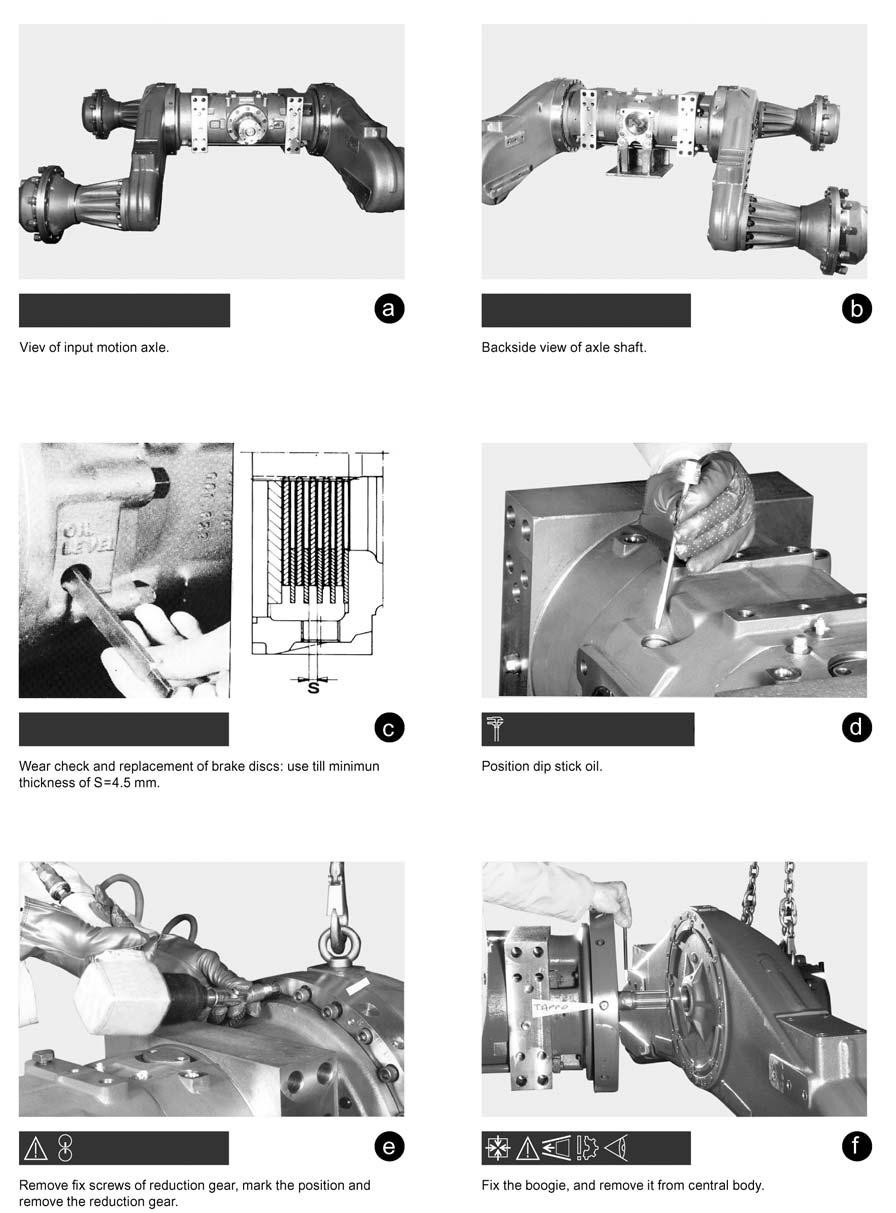
10 DISASSEMBLING GROUP 7-10
11 DISASSEMBLING GROUP 7-11

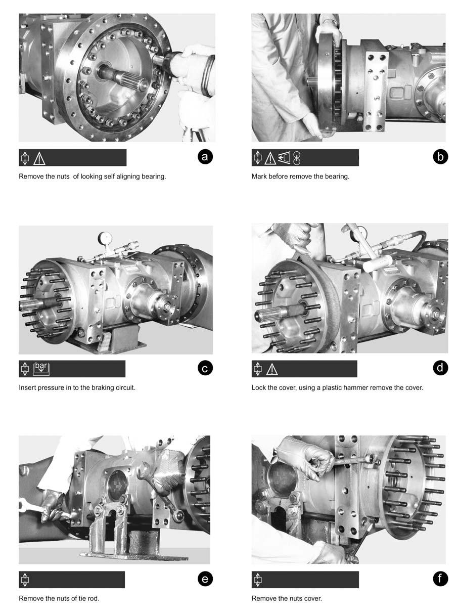
12 DISASSEMBLING BRAKING UNIT 7-12
13 DISASSEMBLING BRAKING UNIT 7-13

14 ASSEMBLING THE BRAKING UNIT 7-14

15 DISASSEMBLING THE NEGATIVE BRAKE 7-15

16 ASSEMBLING THE NEGATIVE BRAKE 7-16

17 ASSEMBLING THE BRAKE UNIT 7-17

18 ASSEMBLING THE BRAKE UNIT 7-18

19 ASSEMBLING GROUP 7-19

20 ASSEMBLING GROUP 7-20

21 DISASSEMBLING AND ASSEMBLING UNIT HUB 151 TYPE 5 SCREWS AND 5 DOWEL CAT3 7-21

22 DISASSEMBLING AND ASSEMBLING UNIT HUB 151 TYPE 5 SCREWS AND 5 DOWEL CAT3 7-22

23 DISASSEMBLING AND ASSEMBLING UNIT HUB 151 TYPE 5 SCREWS AND 5 DOWEL CAT3 7-23

24 DISASSEMBLING AND ASSEMBLING UNIT HUB 151 TYPE 8 PILOT SCREWS CAT3 7-24

25 DISASSEMBLING AND ASSEMBLING UNIT HUB 151 TYPE 10 SCREWS AND 10 BUSH CAT3 7-25

26 DISASSEMBLING AND ASSEMBLING PLANETARY REDUCTION 6,

27 DISASSEMBLING AND ASSEMBLING PLANETARY REDUCTION 6,

28 DISASSEMBLING UNIT HUB 7-28

29 DISASSEMBLING UNIT HUB 7-29

30 ASSEMBLING REDUCTION GEAR 7-30

31 ASSEMBLING REDUCTION GEAR 7-31

32 ASSEMBLING REDUCTION GEAR 7-32

33 DISASSEMBLING REDUCTION GEAR 7-33

34 DISASSEMBLING REDUCTION GEAR 7-34

35 DISASSEMBLING REDUCTION GEAR 7-35

36 ASSEMBLING REDUCTION GEAR 7-36

37 REMOVAL OPTION UNITS
38 TECHNICAL DOCUMENTATION 7-38
39 /93 5 Bolts 5 Pins Wheel End Ratio 6.23 cat 3 o Ball Bearing 7-39
40 /93 New Boogle Large Gears 7-40

41 /96 10 Pilot Bolts Hub Reduction 6.23 Cat 3 Roller Bearing 7-41

42 /96 Idle Bearing 7-42
43 /98 Tapper Roller Bearing 7-43

44 /96 Pilot Studs Hub Reduction 6.23 Version 2 o 7-44

45 /96 Triple Shaft 7-45

46 /96 Triple Shaft New Walking Beam Bearing 7-46

47 /94 Single Shaft 7-47

48 /97 Bolts Bushing and Plate 7-48
Service Manual. Axle 213
 Service Manual Axle 213 ASM-0026E June 2012 CONTENTS INTRODUCTION... 5 SPECIFICATIONS...6 DEFINITION OF VIEWPOINTS... 6 DATA PLATE... 6 CONVERSION TABLES... 7 TORQUE SPECIFICATIONS... 8 COARSE PITCH...
Service Manual. Axle 212
 Service Manual Axle 212 ASM-0025E October 2013 CONTENTS INTRODUCTION... 7 SPECIFICATIONS...9 DEFINITION OF VIEWPOINTS... 9 DATA PLATE... 9 CONVERSION TABLES... 10 TORQUE SPECIFICATIONS... 11 COARSE PITCH...
Off-Highway Axle Planetary Wheel Ends
 Maintenance Manual MM-1189 Off-Highway Axle Planetary Wheel Ends Revised 06-16 Service Notes About This Manual This manual provides service and repair procedures for planetary wheel ends on off-highway
MANUAL TRANSAXLE Return to Main Table of Contents
 MANUAL TRANSAXLE Return to Main Table of Contents GENERAL... 2 MANUAL TRANSAXLE CONTROL... 12 SHIFT LEVER ASSEMBLY... 14 MANUAL TRANSAXLE... 15 MANUAL TRANSAXLE ASSEMBLY... 17 FIFTH SPEED SYNCHRONIZER
SECTION ZF FRONT AXLE
 04-101.01/ 1 2011JA14 SECTION 04-101.01 6 3 5 1 2 9 1. Upper radius rod 2. Lower radius rod 3. Caliper 4. BRAKE Disk 5. Pneumatic connector 6. Hub 7. steering knuckle 8. Grease Fitting 9. Pneumatic connector
LIFT TRUCK SERIES: G35S-2 G40S-2 G45S-2 G40SC-2 G45SC-2 G50SC-2. November 15, 2000 CODE 3150 LT3150-L0 SUBJECT: NEW DRIVE AXLE
 LIFT TRUCK SERIES: G35S-2 G40S-2 G45S-2 G40SC-2 G45SC-2 G50SC-2 November 15, 2000 CODE 3150 LT3150-L0 SUBJECT: NEW DRIVE AXLE A new drive axle has been introduced in the above model lift trucks. The purpose
MAINTENANCE MANUAL DP-265
 MAINTENANCE MANUAL DP-265 Drive Gears Sisu Axles, Inc. Autotehtaantie 1 P.O. Box 189 FIN-13101 Hämeenlinna Finland Phone int + 358 204 55 2999 Fax int + 358 204 55 2900 DP265DG.PDF (2/2003) k Table of
DRIVE AXLE Nissan 240SX DESCRIPTION & OPERATION AXLE RATIO & IDENTIFICATION AXLE SHAFT & BEARING R & I DRIVE SHAFT R & I
 DRIVE AXLE 1990 Nissan 240SX 1990 DRIVE AXLES Rear Axle - R200 240SX, 300ZX DESCRIPTION & OPERATION The axle assembly is a hypoid type gear with integral carrier housing. The pinion bearing preload adjustment
1984 Dodge W250 PICKUP
 1984 Dodge W250 PICKUP Submodel: Engine Type: V8 Liters: 5.2 Fuel Delivery: CARB Fuel: GAS Dana 44 MODELS THROUGH 1984 2. Raise and safely support the vehicle, then remove the wheel hub and bearings as
Front Hub and Disc (4WD Model)
") 4C 8 DRIVE SHAFT SYSTEM Disassembled View Front Hub and Disc (4WD Model) 411RW001 Legend (1) Bolt (2) Cap (3) Snap Ring and Shim (4) Hub Flange (5) Lock Washer and Lock Screw (6) Hub Nut (7) Outer Bearing
4C 8 DRIVE SHAFT SYSTEM Disassembled View Front Hub and Disc (4WD Model) 411RW001 Legend (1) Bolt (2) Cap (3) Snap Ring and Shim (4) Hub Flange (5) Lock Washer and Lock Screw (6) Hub Nut (7) Outer Bearing
BRAKE E
 8-1 GENERAL...8-2 SPECIFICATIONS...8-6 COMPONENTS...8-7 FRONT BRAKE...8-12 DISASSEMBLY INSPECTION REASSEMBLY (Pn1, Cu2 3 TON SERIES)...8-12 DISASSEMBLY INSPECTION REASSEMBLY (Pn2 3 TON SERIES)...8-17 BRAKE
DRIVE AXLE - INTEGRAL HOUSING
 DRIVE AXLE - INTEGRAL HOUSING 1993 Toyota Celica 1993 DRIVE AXLES Toyota Differentials & Axle Shafts - Integral Housing Toyota; Celica All-Trac DESCRIPTION Drive axle assembly is a hypoid type with integral
Input Adjusting Ring Leak Repair Procedure for Meritor MT-14X Series Forward Differential Carriers
 Revised 01-16 Technical Bulletin Input Adjusting Ring Leak Repair Procedure for Meritor MT-14X Series Forward Differential Carriers Revised 1 Technical 01- Bulletin 16 Hazard Alert Messages Read and observe
CLUTCH CONTENTS SERVICE DIAGNOSIS. (a) Worn or damaged disc assembly. (b) Grease or oil on disc facings. (c) Improperly adjusted cover assembly.
 Worn or damaged disc assembly. (b) Grease or oil on disc facings. (c) Improperly adjusted cover assembly.") CLUTCH CONTENTS -GROUP 6 Page CLUTCH HOUSING ALIGNMENT... 6 CLUTCH PEDAL FREE PLAY 1 CLUTCH RELEASE BEARING 5 CLUTCH RELEASE FORK... 5 CLUTCH SERVICING 2 PILOT BUSHING CRANKSHAFT TO TRANSMISSION DRIVE
CLUTCH CONTENTS -GROUP 6 Page CLUTCH HOUSING ALIGNMENT... 6 CLUTCH PEDAL FREE PLAY 1 CLUTCH RELEASE BEARING 5 CLUTCH RELEASE FORK... 5 CLUTCH SERVICING 2 PILOT BUSHING CRANKSHAFT TO TRANSMISSION DRIVE
SERVICE MANUAL STEERING AND RIGID DRIVE AXLES SERIES 068. Date Revision Description Owner 06/10/ Document emission PM
 SERVICE MANUAL STEERING AND RIGID DRIVE AXLES SERIES 068 Date Revision Description Owner 06/10/09 1.0 Document emission PM COMER INDUSTRIES Axles & Wheel Drive Units Via Magellano, 37-42046 Reggiolo (RE)
REAR AXLE Click on the applicable bookmark to selected the required model year
 REAR AXLE 27-1 REAR AXLE CONTENTS GENERAL INFORMATION.................. 2 SERVICE SPECIFICATIONS................. 3 LUBRICANTS.............................. 3 SEALANTS AND ADHESIVES.............. 4 SPECIAL
SECTION 5B MANUAL TRANSMISSION TABLE OF CONTENTS
 SECTION 5B MANUAL TRANSMISSION TABLE OF CONTENTS General Description and Operation... 5B-2 Shift Lever... 5B-2 Transmission Assembly... 5B-2 Specifications... 5B-3 Diagnostic Information and Procedures...
Maintenance Manual FP-330 Drive Gear
 Maintenance Manual FP-330 Drive Gear Sisu Axles, Inc. Autotehtaantie 1 P.O. Box 189 FIN-13101 Hämeenlinna Finland Phone int + 358 204 55 2999 Fax int + 358 204 55 2900 FP330DG 2/2008 Maintenance Manual
SISU DP-330 DRIVE GEAR. Maintenance Manual
 SISU DP-330 DRIVE GEAR Maintenance Manual Sisu Axles, Inc. Autotehtaantie 1 PO Box 189 Fin-13101 Hameenlinna Finland Phone +358 204 55 2999 Fax +358 204 55 2900 DP330DG.PDF (3/2007) TABLE OF CONTENTS
*THIS KIT IS NOT INTENDED FOR VEHICLES WITH ABS*
 *THIS KIT IS NOT INTENDED FOR VEHICLES WITH ABS* Notes: New full-cast rotors from 1990 or newer Wrangler must be used with this kit, this rotor (ITT #65225 or equivalent) has a.25 thick mounting flange.
INSTALLATION INSTRUCTIONS
 INSTALLATION INSTRUCTIONS REAR DISC BRAKE CONVERSION KIT A126-1 1973-87 CHEVROLET 1/2 TON 2WD Thank you for choosing STAINLESS STEEL BRAKES CORPORATION for your braking needs. Pleases take the time to
AUTOMATIC TRANSAXLE AUTOMATIC TRANSAXLE SYSTEM... COMPONENT PARTS...
 SYSTEM....... COMPONENT PARTS.................... OIL PUMP.............................. DIRECT CLUTCH........................ FORWARD CLUTCH..................... SECOND BRAKE........................ UNDERDRIVE
TROUBLESHOOTING SPECIAL TOOL ASSEMBLY AND ADJUSTMENT
 1 INDEX Models FD, FE, FF and SG REAR AXLE 10-1 10-108E-07 CHAPTER 10 REAR AXLE Models FD, FE, FF and SG TROUBLESHOOTING...10-2 10 SPECIAL TOOL...10-3 WHEEL HUB AND RELATED PARTS DISASSEMBLY...10-7 INSPECTION...10-9
SECONDARY SERVICE EXTERIOR R-12DC VALVE (MODEL WITH 4 VERTICAL DELIVERY PORTS) DELIVERY COVER SECONDARY RELAY PISTON VALVE RETAINER INLET EXHAUST
 DELIVERY COVER SECONDARY RELAY PISTON VALVE RETAINER INLET EXHAUST") SD-03-1068 Bendix R-12DC Relay Valve with Biased Double Check PRIMARY SECONDARY EXTERIOR R-12DC (MODEL WITH 4 VERTICAL DELIVERY PORTS) SUPPLY (2) EXTERIOR R-12DC (MODEL WITH 2 HORIZONTAL PORTS) DELIVERY
SD-03-1068 Bendix R-12DC Relay Valve with Biased Double Check PRIMARY SECONDARY EXTERIOR R-12DC (MODEL WITH 4 VERTICAL DELIVERY PORTS) SUPPLY (2) EXTERIOR R-12DC (MODEL WITH 2 HORIZONTAL PORTS) DELIVERY
SERVICE MANUAL. 915 Series Axle
 SERVICE MANUAL 915 Series Axle Issue 1 September 2003 CONTENT: 1 INTRODUCTION Page 3-2 GENERAL DESCRIPTION Page 3-3 IDENTIFICATION Page 3-4 GENERAL SERVICE INFORMATION Page 5 -.1 4.1 Routine Maintenance
Steer Axles. Spicer. Service Manual. AXSM-0070 November Front Drive Steer Axle Model 60
 Spicer Steer Axles Service Manual AXSM-0070 November 2017 Front Drive Steer Axle Model 60 General Information The description and specifications contained in this service publication are current at the
SISU MP-330 DRIVE GEAR. Maintenance Manual
 SISU MP-330 DRIVE GEAR Maintenance Manual Sisu Axles, Inc. Autotehtaantie 1 PO Box 189 Fin-13101 Hameenlinna Finland Phone +358 204 55 2999 Fax +358 204 55 2900 MP330DG.PDF (4/2007) TABLE OF CONTENTS
DRIVE AXLE - 4WD MODELS WITH INTEGRAL HOUSING
 DRIVE AXLE - 4WD MODELS WITH INTEGRAL HOUSING 1988 Toyota Celica DRIVE AXLES Toyota Integral Housing Celica (Rear) DESCRIPTION housing. Drive axle assembly is hypoid type with integral carrier AXLE RATIO
MANUAL TRANSMISSION MUA 5C (4X2, 4X4) AND TREMEC T5R(4X2)
 AND TREMEC T5R(4X2)") MANUAL TRANSMISSION 7B 1 RODEO TRANSMISSION MANUAL TRANSMISSION MUA 5C (4X2, 4X4) AND TREMEC T5R(4X2) CONTENTS Service Precaution...................... 7B 2 General Description..................... 7B
MANUAL TRANSMISSION 7B 1 RODEO TRANSMISSION MANUAL TRANSMISSION MUA 5C (4X2, 4X4) AND TREMEC T5R(4X2) CONTENTS Service Precaution...................... 7B 2 General Description..................... 7B
This kit can not improve any gear selection condition related to worn or damaged synchromesh components.
 WEVO GateShift kit This kit includes all the parts required to install the WEVO GateShift kit. The kit will improve accuracy of gear selection and protect the internals of a 915 transmission from the extraneous
Rear Axle Single-Reduction Carrier
 Revised 08-0 Rear Axle Single-Reduction Carrier Model MS-3 Maintenance Manual MM-030 Service Notes Service Notes Notes About This Manual This manual provides instructions for Meritor s model MS-3 single-reduction
AUTOMATIC TRANSMISSIONS Mitsubishi F3A20 Series TRANSMISSION APPLICATION TABLE
 Article Text ARTICLE BEGINNING AUTOMATIC TRANSMISSIONS Mitsubishi F3A20 Series APPLICATION TRANSMISSION APPLICATION TABLE Vehicle Application Transmission Model Colt 3-Speed (1990-94)... F3A21 Colt Vista
SECTION 3A FRONT DRIVE AXLE TABLE OF CONTENTS SPECIFICATIONS GENERAL SPECIFICATIONS. Description Drive Shaft Type. CV Joint Axle Housing Type
 SECTION 3A FRONT DRIVE AXLE TABLE OF CONTENTS Specifications........................ 3A-1 General Specifications.................. 3A-1 Fastener Tightening Specifications......... 3A-2 Component Locator...................
Brake System H TX, H2.0TXS [B475]; H TX [B466] Safety Precautions Maintenance and Repair
![Brake System H TX, H2.0TXS [B475]; H TX [B466] Safety Precautions Maintenance and Repair](/thumbs/86/93834005.jpg "Brake System H TX, H2.0TXS [B475]; H TX [B466] Safety Precautions Maintenance and Repair") HMM180001 Brake System H1.5-1.8TX, H2.0TXS [B475]; H2.5-3.5TX [B466] Safety Precautions Maintenance and Repair When lifting parts or assemblies, make sure all slings, chains, or cables are correctly fastened,
HMM180001 Brake System H1.5-1.8TX, H2.0TXS [B475]; H2.5-3.5TX [B466] Safety Precautions Maintenance and Repair When lifting parts or assemblies, make sure all slings, chains, or cables are correctly fastened,
INSTALLATION INSTRUCTIONS
 INSTALLATION INSTRUCTIONS REAR DISC CONVERSION KIT A126-2 1988-98 C1500 2WD 10" REAR DRUM Thank you for choosing STAINLESS STEEL BRAKES CORPORATION for your braking needs. Pleases take the time to read
TABLE OF CONTENTS 0 FRONT DRIVE , WHEEL HUB , WHEEL HUB BEARING , KNUCKLE
 Subsection 01 (TABLE OF CONTENTS) TABLE OF CONTENTS 0 FRONT DRIVE... 06-02-1 1, WHEEL HUB... 06-02-2 2, WHEEL HUB BEARING... 06-02-2, KNUCKLE... 06-02- FINAL DRIVE... 06-0-1 1, DRIVE CHAIN... 06-0-2 2,
615 Service Manual SERVICE MANUAL. 615 Series Axle
 SERVICE MANUAL 615 Series Axle Issue 1 - February 2002 CONTENT: 1 INTRODUCTION... Page - 1-2 GENERAL DESCRIPTION... Page - 1-3 IDENTIFICATION... Page - 1-4 GENERAL SERVICE INFORMATION... 4.1 Routine Maintenance...
MAINTENANCE MANUAL. Differential Axle MS Edition october/11
 MAINTENANCE MANUAL Differential Axle MS - 113 Edition october/11 Index 1 - Notes to Technical Assistance... 03 2 - Exploded View MS-113... 04 3 - Exploded View MS-113 Plus... 05 4 - Introduction... 06
1. General Description
 1. General Description A: SPECIFICATION 1. MANUAL TRANSMISSION AND FRONT DIFFERENTIAL Type Transmission gear ratio Front reduction gear Rear reduction gear Front differential Center differential Final
SPECIAL TOOLS Dodge Pickup 5.9L Eng R3500. Fig 1: Identifying Remover C-3985-B (Special Tool) 9/6/13 Printer Friendly View
 9/6/13 Printer Friendly View") Procedures 2003 Dodge Pickup 5.9L Eng R3500 manual transmission SPECIAL TOOLS Fig 1: Identifying Remover C-3985-B (Special Tool) www2.prodemand.com/print/index?content=tabs&module=true&tab=true&terms=true&ymms=false&classname=
Procedures 2003 Dodge Pickup 5.9L Eng R3500 manual transmission SPECIAL TOOLS Fig 1: Identifying Remover C-3985-B (Special Tool) www2.prodemand.com/print/index?content=tabs&module=true&tab=true&terms=true&ymms=false&classname=
Betico SB1 Compressor. Unloader Kit Installation Manual
 Betico SB1 Compressor Unloader Kit Installation Manual Contents 1. Sample of BOM for Unloader Kit Page 3 2. Regulation kit plumbing diagram Page 4 3. Disassemble standard inlet valves from machine Page
MP140 - SERVICE Dodge Nitro R/T TRANSFER CASE MP140 - Service Information - Nitro DESCRIPTION
 1 - INPUT SEAL 15 - WEAR SLEEVE 2 - VENT 16 - FLANGE 3 - FRONT CASE 17 - FLANGE SEAL 4 - INPUT GEAR 18 - FLANGE NUT 5 - PILOT BEARING 19 - ID. TAG 6 - PLANETARY GEAR 20 - DRAIN/FILL PLUGS 7 - SPROCKET
Features. Marathon SL TECHNICAL CHARACTERISTICS. Sliding bushes: made of friction free and wear free material.
 Features TECHNICAL CHARACTERISTICS Fork with Ø30 mm legs with "Double Air" damping system. Adjustment of the air preload (positive air) on both legs. Adjustment of the rebound damping (negative air) on
REAR FINAL DRIVE SECTION RFD CONTENTS D DRIVELINE/AXLE RFD-1 RFD
 REAR FINAL DRIVE D DRIVELINE/AXLE SECTION RFD A REAR FINAL DRIVE B C RFD CONTENTS E PRECAUTIONS... 2 Precautions... 2 PREPARATION... 3 Special Service Tools... 3 Commercial Service Tools... 5 NOISE, VIBRATION
6 15. Ease off the adjuster and remove t h e spreader REAR DIFFERENTIAL-ONE TEN. 8. Remove the fixings and withdraw the differential bearing caps.
 ...,.....,... OVERHAUL REAR AXLE DIFFERENTIAL.. ASSEMBLY (SALISBURY) LAND ROVER ONE TEN MODELS 8. Remove the fixings and withdraw the differential bearing caps. Service tools: 47 screw press; 131 C axle
DIFFERENTIALS & AXLE SHAFTS
 DIFFERENTIALS & AXLE SHAFTS 2001 Chevrolet Camaro 2000-01 DRIVE AXLES General Motors Differentials & Axle Shafts Chevrolet; Camaro Pontiac; Firebird DESCRIPTION & OPERATION Drive axle is a semi-floating,
Check valves are for the prevention of backflow. Particular check valves perform additional services as follows:
 KENNEDY VALVE Division of McWane, Inc. 1021 East Water Street P.O. Box 931 Elmira, New York 14902-0931 Telephone (607) 734-2211 Fax (607) 734-1003 KENNEDY VALVE RESILIENT SWING CHECK MAINTENANCE MANUAL
 AUTOGARD SERIES 820 TORQUE LIMITER Installation and Maintenance Manual DB0009 Issue 11 21 Feb 2017 British Autogard Ltd 2 Wilkinson Rd., Love Lane Industrial Estate, Cirencester, Glos., GL7 1YT UK Tel.
S-1 LOAD SENSOR VALVES, PART NOS & PART NOS &
 S-1 LOAD SENSOR VALVES, PART NOS. 578553-0001 & 578553-0011 PART NOS. 665133-0001 & 665133-0011 AUGUST, 2005 Supersedes issue dated December, 2004 NOTE: The following description and operation is based
TSM54/52 MANUAL TRANSMISSION
 3B-1 SECTION 00 3B TSM54/52 MANUAL TRANSMISSION Table of Contents GENERAL INFORMATION... 3B-3 Overview... 3B-3 Specifications... 3B-4 System components... 3B-5 Shifting mechanism... 3B-17 Diagnostic information
Amboid Rear Differential Carrier
 Maintenance Manual MM-0250 Amboid Rear Differential Carrier Rear/Rear Carrier on MT-40-143MA-N Tandem Drive Axles Revised 09-05 Service Notes About This Manual This manual provides instructions for the
Kysor On/Off Rear Air Fan Drive
 . Proper precautions must be taken to prevent personal injury from contact with moving parts, unintended engine start, or other hazards present when working with powered equipment. Refer to the vehicle
1 M-3000-H4 F150 4X4 Lowering Kit
 READ INSTRUCTIONS COMPLETELY THROUGH BEFORE STARTING. IT IS RECOMMENDED THAT INSTALLATION BE DONE BY A QUALIFIED MECHANIC. REPLACE ALL STOCK PARTS THAT ARE DAMAGED OR WORN. ALWAYS WEAR EYE PROTECTION.
Transmission Overhaul Procedures-Bench Service
 How to Assemble the Lower Reverse Idler Gear Assembly Special Instructions In 1996 Eaton changed the reverse idler system design. In the nut design, the reverse idler bearing was lubricated through a hole
BIG BRAKE KIT FOR TJ, ZJ, XJ D44 & D30
 BIG BRAKE KIT FOR TJ, ZJ, XJ D44 & D30 16 KIT PART NUMBER 41002010AA 17 KIT PART NUMBER 41002015AA Installation Guide (Updated 12/01/09) Page 1 of 11 PLEASE READ BEFORE YOU START IN ORDER TO INSTALL THIS
PARTAN. Installation Manual LOCKER
 S PARTAN Installation Manual LOCKER Also available from USA Standard Gear: Ring & Pinion Sets Master Overhaul Kits Axles Note about your carrier: Before beginning to tear down your differential, please
1. General Description
 1. General Description A: SPECIFICATIONS 1. Type Transmission gear ratio Front reduction gear Rear reduction gear 2. TRANSMISSION GEAR OIL Recommended oil Final Transfer 5-forward speeds with synchromesh
 DRUM BRAKE RIMS Periodic inspection of drum brake rims is necessary to determine indications of uneven or excessive wear. In general, brake rim failures other that regular wear are caused by brake linings
This file is available for free download at
 This file is available for free download at http://www.iluvmyrx7.com This file is fully text-searchable select Edit and Find and type in what you re looking for. This file is intended more for online viewing
Proudly Distributed by
 Proudly Distributed by Loctite Penetrating Oil Heavy-duty penetrant for rusted and frozen assemblies. Works quickly to penetrate and loosen rust, tar, grease, dirt, carbon deposits and corrosion from metal
SERVICE INFORMATION 11-1 FRONT WHEEL/SUSPENSION/ STEERING XL FRONT WHEEL 11 7 FORK STEERING STEM 11 18
 XL200 11. FRONT WHEEL/SUSPENSION/ STEERING SERVICE INFORMATION 11 1 TROUBLESHOOTING 11 2 HANDLEBAR 11 3 FRONT WHEEL 11 7 FORK 11 11 STEERING STEM 11 18 SERVICE INFORMATION GENERAL A contaminated brake
9. DRIVE AND DRIVEN PULLEYS/ KICK STARTER AGILITY ~6.0kg-m g-m g-m 9-0
 9 5.0~6.0kg-m 3.5-4.5g-m 9 3.5-4.0g-m 9-0 SERVICE INFORMATION...9-1 DRIVE BELT...9-5 TROUBLESHOOTING...9-1 DRIVE PULLEY...9-6 LEFT CRANKCASE COVER...9-2 CLUTCH/DRIVEN PULLEY...9-9...9-2 SERVICE INFORMATION
2005 Toyota RAV AUTOMATIC TRANSMISSIONS U240E & U241E Overhaul
 2001-05 AUTOMATIC TRANSMISSIONS U240E & U241E Overhaul APPLICATION CAUTION: Flush oil cooler and oil cooler lines prior to transaxle installation. Oil cooling system contamination may cause premature transaxle
Single reduction Differential Carrier Series 7 - MS15 - MS16 - MS17 - MR15 Revised April 2003
 an ArvinMeritor brand Maintenance manual no. MM-0140 Single reduction Differential Carrier Series 7 - MS15 - MS16 - MS17 - MR15 Revised April 2003 Table of contents pg. 05 Section 1: Introduction 06 Description
CHASSIS CONTENTS EXTERIOR PARTS 6-1 FRAME COVER 6-2 REAR FRAME COVER 6-4 FRONT WHEEL 6-6 FRONT BRAKE 6-10 HANDLEBARS 6-17 FRONT FORK 6-19
 CHASSIS CONTENTS EXTERIOR PARTS 6- FRAME COVER 6- REAR FRAME COVER 6-4 FRONT WHEEL 6-6 FRONT BRAKE 6-0 HANDLEBARS 6-7 FRONT FORK 6-9 STEERING 6-6 REAR WHEEL 6-3 REAR BRAKE 6-39 6 REAR SHOCK ABSORBER 6-43
Single Reduction Differential Carriers
 Revised 10-00 $2.50 Single Reduction Differential Carriers Maintenance Manual 5 Standard Carriers Including: Single Axles, Rear of Tandem Axles, Front Drive Steering Axles Excluding RS and RT Series (Rear
POWER STEERING TO INDEX POWER STEERING SYSTEM PRECAUTIONS... OPERATION CHECK... PROBLEM SYMPTOMS TABLE... VANE PUMP ASSEMBLY COMPONENTS...
 TO INDEX STEERING POWER STEERING POWER STEERING SYSTEM PRECAUTIONS.............................................. OPERATION CHECK......................................... PROBLEM SYMPTOMS TABLE.................................
DF 43 DIFFERENTIAL REAR DIFFERENTIAL CARRIER ASSEMBLY REMOVAL
 DIFFERENTIAL REAR DIFFERENTIAL CARRIER ASSEMBLY 43 REMOVAL 1. DISCONNECT CABLE FROM NEGATIVE BATTERY TERMINAL 2. REMOVE REAR WHEEL 3. DRAIN BRAKE FLUID 4. REMOVE REAR BRAKE DRUM SUB-ASSEMBLY (See page
Front mechanical suspensions
 FRONT MECHANICAL SUSPENSIONS 9 PRINT 603.43.351/D Front mechanical suspensions Page DESCRIPTION... 11 ARTICULATED QUADRILATERAL SUSPENSION WITH TRANSVERSE LEAF SPRING... 11 SPECIFICATIONS AND DATA... 12
Maintenance Instructions
 General Note These instructions contain information common to more than one model of Bevel Gear Drive. To simplify reading, similar models have been grouped as follows: GROUP 1 Models 11, 0, 1,, (illustrated),,
1988 Chevrolet Pickup V SUSPENSION - FRONT (4WD)' 'Front Suspension - "V" Series 1988 SUSPENSION - FRONT (4WD) Front Suspension - "V" Series
' 'Front Suspension - V Series 1988 SUSPENSION - FRONT (4WD) Front Suspension - V Series") 1988 SUSPENSION - FRONT (4WD) Front Suspension - "V" Series DESCRIPTION NOTE: Vehicle serial numbers used in this article has been abbreviated for common reference to Chevrolet and GMC models. Chevrolet
1988 SUSPENSION - FRONT (4WD) Front Suspension - "V" Series DESCRIPTION NOTE: Vehicle serial numbers used in this article has been abbreviated for common reference to Chevrolet and GMC models. Chevrolet
NP231 SHORT SHAFT "FIXED YOKE" KIT
 Page 1 of 11 KIT CONSISTS OF: No. Qty Part No. Description 1. 1 51-7905 TAILHOUSING, DIECAST 2. 1 52-7905 SHAFT, MAIN OUTPUT 3. 1 300474 SEAL WASHER, REAR YOKE 4 1 300475 YOKE, C.V. REAR 5. 1 300476 NUT,
Operation & Maintenance Instruction , S.9. MARCH, 2005 Supersedes issue dated March, 2003
 S-1 LOAD SENSOR VALVES, SUSPENSION MOUNTING - PART NO. 664801-0001 SUSPENSION MOUNTING - PART NO. 665132-0001 FLOOR MOUNTING - PART NO. 664801-0002 FLOOR MOUNTING - PART NO. 665132-0002 MARCH, 2005 Supersedes
"HS-2A" DISC BRAKE UNIT CALIPER
 "HS-2A" DISC BRAKE UNIT CALIPER Part No. 0695887 February, 2004 This document is comprised of pages i through viii and pages 1 through 27. Copyright 2004 Wabtec Corporation. P.O. BOX 11 SPARTANBURG, SC
M-4851-M8A SUPER 8.8 IRS MUSTANG AUTOMATIC PINION FLANGE KIT
 Please visit fordperformanceracingparts.com for the most current instruction information!!! PLEASE READ ALL OF THE FOLLOWING INSTRUCTIONS CAREFULLY PRIOR TO INSTALLATION. AT ANY TIME YOU DO NOT UNDERSTAND
1 Part Number: M-2300-Y Part Description: S550 Mustang-Shelby Brake Upgrade Kit Installation Instructions
 Please visit www.performanceparts.ford.com for the most current instruction and warranty information. PLEASE READ ALL OF THE FOLLOWING INSTRUCTIONS CAREFULLY PRIOR TO INSTALLATION. AT ANY TIME YOU DO NOT
STEERING LOCATION INDEX
 STEERING LOCATION INDEX 2007 STEERING Power Steering - MX-5 Miata Fig. 1: Identifying Location Of Steering Components AIR BLEEDING CAUTION: Do not turn the steering wheel during the fluid level inspection,
REAR AXLE Click on the applicable bookmark to selected the required model year
 REAR AXLE 27-2 REAR AXLE General Information GENERAL INFORMATION 27100010118 The rear axle is a banjo-type semi-floating type. The axle shaft bearings are: *Single taper bearings for vehicles without
26-LU-L BRACKET-CARRIAGE AND EQUIPMENT, PART NO
 26-LU-L BRACKET-CARRIAGE AND EQUIPMENT, PART NO. 655031 OCTOBER, 2006 NOTE: The following description and operation is based on this device and its components being new or this device and its components
Marzocchi Suspension D-Street 24" D-Street 24" Technical instructions
 Technical instructions Exploded view - D-Street 24" 80 Rif. Code Quantity D-Street 24" 80 - Oil levels Position Oil type Quantity (cc) Right fork leg SAE 7,5-550013 185 Left fork leg SAE 7,5-550013 185
Temperature Sensor Series
 GENERAL DESCRIPTION The patented* No. 85026-Series Temperature Sensor contains a two-position valve operated by temperature variations around the integral sensing bulb. It is used to vent or block a pneumatic
HORSTMAN GREASED LIGHTNING CLUTCH
 HORSTMAN GREASED LIGHTNING CLUTCH Horstman s Greased Lightning (GL) clutch is designed for ultra high performance, and requires expert setup and a serious commitment to maintenance. Warning!!! 1. Clutch
PROPELLER SHAFT GROUP CONTENTS GENERAL DESCRIPTION PROPELLER SHAFT PROPELLER SHAFT DIAGNOSIS SPECIFICATIONS...
 25-1 GROUP 25 CONTENTS GENERAL DESCRIPTION 25-2 DIAGNOSIS 25-2 INTRODUCTION TO DIAGNOSIS 25-2 DIAGNOSTIC TROUBLESHOOTING STRATEGY 25-2 SYMPTOM CHART 25-2 SYMPTOM PROCEDURES 25-3 SPECIAL TOOL 25-4 25-4
WARNING: Only perform this installation if you are experienced, fully equipped mechanic.
 DYNATRAC V3.2 2005-Present Ford Super Duty 250/350-4x4, Front Axle, Free Spin Conversion Kit Some of the less common tools, which will be required: 6 point Spanner socket (OTC #7090-A or equivalent). These
Sherco Setup and Lubrication Guide
 Sherco Setup and This guide is designed to provide the Sherco owner with instructions on how to: Set up a new bike Clean and re-oil the air filter Change the transmission oil Change the fork oil Repack
Brake Pad: Service and Repair Front PADS - BRAKE FRONT
 2005 Dodge Truck RAM 3500 4WD Pickup L6-5.9L DSL Turbo VIN C Page 1 Brake Pad: Service and Repair Front PADS - BRAKE FRONT REMOVAL 1. Raise and support vehicle. 2. Remove the wheel and tire assemblies.
Copyright 1998 Inter-Industry Conference On Auto Collision Repair v.4.0
 Uniform Procedures For Collision Repair BR11 Brakes 1. Description This procedure describes repair, replacement, and inspection requirements for collisiondamaged brake systems. 2. Purpose The purpose of
M&H VALVE RESILIENT SWING CHECK MAINTENANCE MANUAL
 M&H Valve Co. Division of McWANE, Inc. 605 West 23 rd Street P.O. Box 2088 Anniston, AL 36202 Telephone (256) 237-3521 Fax (888) 549-5309 M&H VALVE RESILIENT SWING CHECK MAINTENANCE MANUAL I. SELECTION
DEUBLIN. DEUBLIN Unions H57 H67 H87
 Instructions for Installation and Maintenance Installation Instructions For DEUBLIN H57 H67 H87 19.4.2013 DEUBLIN Italiana S.r.l. Via Guido Rossa, 9 40050 Monteveglio (BO) Italy ++39.051.835611 Fax: ++39.051.832091
DEUBLIN. Installation Instructions DEUBLIN Unions H57 H67 H87
 Instructions for Installation and Maintenance Installation Instructions For DEUBLIN H57 H67 H87 06.4.2012 DEUBLIN Italiana S.r.l. Via Guido Rossa, 9 40050 Monteveglio (BO) Italy ++39.051.835611 Fax: ++39.051.832091
Updates to Maintenance Manual MM-0409 (Revised 02-11): Wheel-End Components/Meritor Conventional and Unitized Wheel Ends
: Wheel-End Components/Meritor Conventional and Unitized Wheel Ends") Technical Bulletin Issued 02-11 Updates to Maintenance Manual MM-0409 (Revised 02-11): Wheel-End Components/Meritor Conventional and Unitized Wheel Ends Issued 1 Technical 02-11 Bulletin Hazard Alert Messages
Technical Bulletin Issued 02-11 Updates to Maintenance Manual MM-0409 (Revised 02-11): Wheel-End Components/Meritor Conventional and Unitized Wheel Ends Issued 1 Technical 02-11 Bulletin Hazard Alert Messages
REMOVAL & INSTALLATION
 REMOVAL & INSTALLATION AXLE SHAFTS & BEARINGS Removal CAUTION: Failure to turn off air suspension power before raising vehicle may result in unexpected inflation or deflation of air springs. DO NOT reconnect
SuperTrac. Axle. Service & Maintenance. Manual
 SuperTrac Axle Service & Maintenance Manual Table of Contents Page Exploded Views Section 1: General Information General Warnings Description of Axle Models Identifications Section 2: Installation Axle
Instructions for changing bearings on all B&C Technologies SP and HP models
 Instructions for changing bearings on all B&C Technologies SP and HP models Tools and material required: 30 mm socket Socket handle with extension or air impact wrench Regular Screwdriver Phillips head
MANUAL TRANS OVERHAUL - BORG-WARNER - T56 6-SPEED MANUAL TRANSMISSIONS Borg-Warner T56 (MM6) 6-Speed
 6-Speed") IDENTIFICATION MANUAL TRANS OVERHAUL - BORG-WARNER - T56 6-SPEED 1998 MANUAL TRANSMISSIONS Borg-Warner T56 (MM6) 6-Speed Transmission has 2 identification labels, located on lower left side of case. One
IDENTIFICATION MANUAL TRANS OVERHAUL - BORG-WARNER - T56 6-SPEED 1998 MANUAL TRANSMISSIONS Borg-Warner T56 (MM6) 6-Speed Transmission has 2 identification labels, located on lower left side of case. One
POWER STEERING PUMP REBUILDING SPK101 Read instructions completely before removal & disassembly
 POWER STEERING PUMP REBUILDING SPK101 Read instructions completely before removal & disassembly DISASSEMBLY: 1. Remove pump from car and allow to drain. 2. Remove pulley from front of pump. This requires
Kysor Rear Air Fan Drives
 On/Off Technology for Heavy-Duty Truck Applications Installation & Service Guide Kysor Rear Air Fan Drives thermal.borgwarner.com For Additional BorgWarner Thermal Systems Information: 800-927-7811 USA
SUSPENSION 2-1 SUSPENSION TABLE OF CONTENTS
 DN SUSPENSION 2-1 SUSPENSION TABLE OF CONTENTS page ALIGNMENT... 1 FRONT SUSPENSION - 4x2... 6 page FRONT SUSPENSION - 4x4... 14 REAR SUSPENSION... 23 ALIGNMENT TABLE OF CONTENTS page AND OPERATION WHEEL
PROPELLER SHAFT & DIFFERENTIAL CARRIER SECTIONPD CONTENTS
 PROPELLER SHAFT & DIFFERENTIAL CARRIER SECTIONPD CONTENTS PREPARATION...2 PROPELLER SHAFT...5 On-Vehicle Service...6 Removal and Installation...7 Inspection...7 Disassembly...7 Assembly...8 ON-VEHICLE
INSTALLATION INSTRUCTIONS
 INSTALLATION INSTRUCTIONS REAR DISC BRAKE CONVERSION KIT A125-3 1965-72 GM A-BODY 10 & 12 BOLT AXLES Thank you for choosing STAINLESS STEEL BRAKES CORPORATION for your braking needs. Pleases take the time