Service Manual. Axle 212
|
|
|
- Betty Sophie Campbell
- 6 years ago
- Views:
Transcription
1 Service Manual Axle 212 ASM-0025E October 2013
2
3 CONTENTS INTRODUCTION... 7 SPECIFICATIONS...9 DEFINITION OF VIEWPOINTS... 9 DATA PLATE... 9 CONVERSION TABLES TORQUE SPECIFICATIONS COARSE PITCH FINE PITCH WHEEL NUT TIGHTENING TORQUES MAINTENANCE MAINTENANCE POINTS MAINTENANCE INTERVALS ADJUSTMENT AND CHECKS LUBRICANT & SEALANT SPECIFICATIONS SAFETY PRECAUTIONS...17 CHECKING WEAR AND REPLACING THE BRAKING DISCS EXPLODED VIEW DISASSEMBLY ASSEMBLY SPECIAL TOOLS T T COMPLETE STEERING CASE EXPLODED VIEW DISASSEMBLY ASSEMBLY DOUBLE U-JOINT EXPLODED VIEW DISASSEMBLY ASSEMBLY SPECIAL TOOLS T T PLANETARY REDUCTION GEAR EXPLODED VIEW DISASSEMBLY ASSEMBLY SPECIAL TOOLS T T T T T STEERING CYLINDER EXPLODED VIEW OPTICAL SENSOR AND MAGNETIC SENSOR DISASSEMBLY ASSEMBLY SPECIAL TOOLS T T
4 DIFFERENTIAL UNIT EXPLODED VIEW DISASSEMBLY ASSEMBLY SPECIAL TOOLS T T BEVEL PINION EXPLODED VIEW DISASSEMBLY ASSEMBLY SPECIAL TOOLS T T T T T T T T T MANUAL EMERGENCY RELASE...83 EXPLODED VIEW RELEASE ADJUST MECHANICAL PARKING BRAKE EXPLODED VIEW DISASSEMBLY ASSEMBLY EXTERNAL HYDRAULIC NEGATIVE BRAKE EXPLODED VIEW DISASSEMBLY ASSEMBLY EXTERNAL HYDRAULIC NEGATIVE BRAKE WITH QUICK RELEASE EXPLODED VIEW DISASSEMBLY ASSEMBLY INCOMING DRUM BRAKE EXPLODED VIEW DISASSEMBLY ASSEMBLY SPECIAL TOOLS T T " INCOMING BRAKE (2 AND 3 FUNCTION VERSIONS) EXPLODED VIEW DISASSEMBLY ASSEMBLY SPECIAL TOOLS T T T
5 NORMAL DIFFERENTIAL UNIT EXPLODED VIEW DISASSEMBLY ASSEMBLY SPECIAL TOOLS T T T T LIMITED SLIP DIFFERENTIAL UNIT (25% AND 45%) EXPLODED VIEW DISASSEMBLY ASSEMBLY SPECIAL TOOLS T T T T HYDRAULIC DIFFERENTIAL LOCK EXPLODED VIEW DISASSEMBLY ASSEMBLY SPECIAL TOOLS T T HYDRAULIC NEGATIVE BRAKE EXPLODED VIEW DISASSEMBLY ASSEMBLY INCORPORATED REDUCTION GEAR AND PINION EXPLODED VIEW DISASSEMBLY ASSEMBLY SPECIAL TOOLS T T T T T T
6 6
7 INTRODUCTION The efficiency and continued operation of mechanical units depend on constant, correct maintenance and also on efficient repair work, should there be a break-down or malfunction. The instructions contained in this manual have been based on a complete overhaul of the unit. However, it is up to the mechanic to decide whether or not it is necessary to assemble only individual components, when partial repair work is needed. The manual provides a quick and sure guide which, with the use of photographs and diagrams illustrating the various phases of the operations, allows accurate work to be performed.all the information needed for correct disassembly, checks and assembly of each individual component is set out below. In order to remove the differential unit from the vehicle, the manuals provided by the vehicle manufacturer should be consulted. In describing the following operations it is presumed that the unit has already been removed from the vehicle. IMPORTANT: In order to facilitate work and protect both working surfaces and operators, it is advisable to use proper equipment such as: trestles or supporting benches, plastic or copper hammers, appropriate levers, pullers and specific spanners or wrenches. Before going on to disassemble the parts and drain the oil, it is best to thoroughly clean the unit, removing any encrusted or accumulated grease. INTRODUCTORY REMARKS: All the disassembled mechanical units should be thoroughly cleaned with appropriate products and restored or replaced if damage, wear, cracking or seizing have occurred. In particular, thoroughly check the condition of all moving parts (bearings, gears, ring gear and pinion, shafts) and sealing parts (o-rings, oil shields) which are subject to major stress and wear. In any case, it is advisable to replace the seals every time a component is overhauled or repaired. During assembly, the sealing rings must be lubricated on the sealing edge. In the case of the ring gear and pinion, replacement of one component requires the replacement of the other one. During assembly, the prescribed pre-loading, backlash and torque of parts must be maintained. CLASSIFICATION: This manual classifies units according to part numbers. For a correct interpretation, classification is indicated as follows: = up to the part number = from the part number on When no classification is given, disassembly and assembly operations are the same for all versions. SPECIFIC EQUIPMENT AND SPARE PARTS: The drawings of all specific tools required for maintenance and repair work can be found at the end of this manual ; spare parts may be ordered either from the vehicle manufacturer or directly from the Service Centers or Authorized Distributors of SPICER. 7
8 8
9 SPECIFICATIONS DEFINITION OF VIEWPOINTS DATA PLATE MFG. BY CLARK-HURTH COMPONENTS S.P.A Arco (Trento) MADE IN ITALY 1 - Model number 2 - Serial number 3 - Lubricant 9
10 CONVERSION TABLES CONVERSION TABLES UNITS OF PRESSURE 1 ATM=1 BAR=105 PA=14.4 PSI UNIT OF WEIGHT N dan kn kg lbs 1N 1 0,1 0,001 0,102 0,225 1daN ,01 1,02 2,25 1kN kg 9,81 0,981 0, ,205 UNITS OF TORQUE N m dan m kn m kg m lb in 1N m 1 0,1 0,001 0,102 8,854 1daN m ,01 1,02 88,54 1kN m kg m 9,81 0,981 0, ,8 1 lb in 0,1129 0, , ,
11 TORQUE SPECIFICATIONS TORQUE SPECIFICATIONS COARSE PITCH SIZE OF BOLT TYPE OF BOLT Loctite Loctite Loctite 270 M6 x 1 mm 9,5 10,5 N m 10,5 11,5 N m 14,3 15,7 N m 15,2 16,8 N m 16,2 17,8 N m 18,1 20 N m M8 x 1,25 mm 23,8 26,2 N m 25,6 28,4 N m 34,2 37,8 N m 36,7 40,5 N m N m 43,7 48,3 N m M10 x 1,5 mm N m N m N m N m N m N m M12 x 1,75 mm N m N m N m N m N m N m M14 x 2 mm N m N m N m N m N m N m M16 x 2 mm N m N m N m N m N m N m M18 x 2,5 mm N m N m N m N m N m N m M20 x 2,5 mm N m N m N m N m N m N m M22 x 2,5 mm N m N m N m N m N m N m M24 x 3 mm N m N m N m N m N m N m M27 x 3 mm N m N m N m N m N m N m M30 x 3,5 mm N m N m N m N m N m N m FINE PITCH SIZE OF BOLT TYPE OF BOLT Loctite Loctite Loctite 270 M8 x 1 mm 25,7 28,3 N m 27,5 30,5 N m 36,2 39,8 N m N m 42,8 47,2 N m 47,5 52,5 N m M10 x 1,25 mm 49,4 54,6 N m 55,2 61 N m 71,5 78,5 N m N m N m N m M12 x 1,25 mm N m N m N m N m N m N m M12 x 1,5 mm N m N m N m N m N m N m M14 x 1,5 mm N m N m N m N m N m N m M16 x 1,5 mm N m N m N m N m N m N m M18 x 1,5 mm N m N m N m N m N m N m M20 x 1,5 mm N m N m N m N m N m N m M22 x 1,5 mm N m N m N m N m N m N m M24 x 2 mm N m N m N m N m N m N m M27 x 2 mm N m N m N m N m N m N m M30 x 2 mm N m N m N m N m N m N m 11
12 TORQUE SPECIFICATIONS WHEEL NUT TIGHTENING TORQUES Wheel nut tightening torques recommended from rim's O.E.M. with reference the the quality of the rim's material. WHEEL NUT TIGHTENING TORQUES RECOMMENDED WHEEL NUTS TORQUE CHARACTERISTICS ILLUSTRATION WHEEL STUD THREAD RIM MATERIAL QUALITY ST 37 **ST 52 WHEEL NUTS WITH INTEGRATED SPHERICAL COLLAR FLAT COLLAR WHEEL NUTS WITH SEPARATE SPHERICAL LOCK WASHER WHEEL NUTS WITH INTEGRATE SEAT CAPTIVE WASHER M18X1,5 mm 330 N m 460 N m M20X1,5 mm 490 N m 630 N m M22X1,5 mm 630 N m 740 N m M18X1,5 mm 270 N m 360 N m M20X1,5 mm 360 N m 450 N m M22X1,5 mm 460 N m 550 N m M18X1,5 mm 260 N m 360 N m M20X1,5 mm 350 N m 500 N m M22X1,5 mm 450 N m 650 N m **RIM'S MATERIAL ST 52 IS RECOMMENDED BY DANA ON AXLE APPLICATION. IT IS THE OPTIMUM MA- TERIAL FOR TIGHTENING THE RIM TO THE HUB. The wheel nut tightening torque is related only on nut thread and stud thread dry. (Without oil or any lubricant). The wheel nut tightening torque takes into consideration not only the nut + stud characteristics, but also the quality of the rim material. THE DANA OFFICIAL TIGHTENING TORQUE TABLE, INCLUDED IN EACH SERVICE MANUAL, SHOWS THE TORQUE FIGURE RELA- TED TO THE BOLT CHARACTERISTIC ONLY. DANA OFFICIAL TIGHTENING TORQUE TABLE NUT MATERIAL QUALITY 8.8 & 10.9 STUD MATERIAL QUALITY 10.9 *ALLOW TIGHT TORQUE M18 x 1,5 mm M18 x 1,5 N m N m M20 x 1,5 mm M20 x 1,5 N m N m M22 x 1,5 mm M22 x 1,5 N m N m *THE TORQUE FIGURE ON NUT AND STUD COUPLING MUST BE RELATED ON STUD MATERIAL QUALITY (DANA AXLE ARE 10.9 ONLY). 12
13 MAINTENANCE MAINTENANCE MAINTENANCE POINTS Oil fill plug 2 - Oil drain plug 3 - Check level plug 13
14 MAINTENANCE MAINTENANCE INTERVALS OPERATION MEMBER FREQUENCY LUBRICANTS Check levels Differential Monthly SAE85W90 (API GL4 - MIL L-2105) Planetary reduction Every 200 hours With additives for oil-bath brakes Oil change Differential Every 800 hrs * Planetary reduction Every 1000 hrs * L.S. Differential Every 700 hrs */*** SAE85W90 (API GL5 - MIL 2105-B) With additives for oil-bath brakes, for units presenting hypoid crown wheel and pinion and/or self-locking differential gear Negative brake Every 1000 hrs * Adjustment Service brake Every 500 hours Tightening Wheel nuts Every 200 hours ** Only for mineral oil use e.g. ATF Dexron II. Make sure that master cylinder seals are suitable for mineral oil. Greasing King Pin Tapered Bearings Seals King Pin Bushings Trunnion Bushings Normal work - Weekly Severe duty - Daily NLGI 2 EP or NLGI 3 EP**** NLGI 2 EP or NLGI 3 EP**** w/moly Additive If working in severe duty conditions half intervals should be used * Initially after 100 working hours ** Initially after 10 working hours *** When it starts sounding noisy **** According to DIN level KP2K-30 (NLGI #2) or KP3K-20 (NLGI #3); ASTM D4950 NLGI #2 GC-LB 14
15 MAINTENANCE LUBRICANT & SEALANT SPECIFICATIONS 1 - Locking, sealing and lubricating materials referred to in this manual are the same used in the shop-floor. 2 - The table below gives an account of the typical applications of each single material, in order to facilitate replacement with similar products marketed by different brand names with different trade marks. LOCTITE 242 Anaerobic product apt to prevent the loosening of screws, nuts and plugs. Used for medium-strength locking. Before using it, completely remove any lubricant by using the specific activator. LOCTITE 243 The oleocompatible alternative to 242. Does not require the activation of lubricated surfaces. LOCTITE 270 Anaerobic product for very-high strength locking of screws and nuts. Before using it, completely remove any lubricant by using the specific activator. To remove parts, it may be necessary to heat them at 80 C approximately LOCTITE 275 Anaerobic product suitable for high-strength locking and sealing of large threaded parts, bolts and stud bolts, for pipe sealing and for protecting parts against tampering; suitable for sealing coupling surfaces with a maximum diametrical clearance of 0.25 mm. LOCTITE 510 Anaerobic product for the hermetic sealing of flanged units and screw holes communicating with fluids. Can seal clearances between flanges up to 0.2 mm. LOCTITE 577 Quick anaerobic sealant for sealing threaded portions of conical or cylindrical unions up to M80. Before using it, remove any lubricant with the specific activator. After polymerisation, disassembly may result rather difficult, so heating may be necessary for larger diameters. LOCTITE 638 Anaerobic adhesive for fast and high-strength gluing of cylindrical metal joints (hub on shaft). Can glue together parts with clearance ranging between 0.1 and 0.25 mm. LOCTITE 648 Anaerobic adhesive for fast and medium-strength gluing of cylindrical metal joints (hub on shaft). Can glue together parts with radial clearance below 0.1 mm. AREXONS (REPOSITIONABLE JOINTING COMPOUND FOR SEALS) Solvent-based sealing compound for elastic seals, drying through evaporation. Used for sealing the outer diameter of sealing rings for rotating shafts with outer metal reinforcement. SILICONE Semi-fluid adhesive material used for sealing and filling and to protect components from environmental and physical elements. Polymerises with non-corrosive dampness. TECNO LUBE/101 (SILICONE-BASED GREASE) Highly adhesive synthetic grease, with silicone compounds added. Applied to adjustment screws with hole communicating with oil-type fluids. Used when frequent adjusting is required. MOLIKOTE (DOW CORNING) Lubricating compound containing molybdenum disulphide, used to lubricate articulation pins and to prevent sticking and oxidation of parts that are not lubricated on a regular basis. (LITHIUM-BASED) GREASE Applied to bearings, sliding parts and used to lubricate seals or parts during assembly. 15
16 MAINTENANCE 16
17 SAFETY PRECAUTIONS 1 - During all operations described in this manual, the axle should be fastened onto a trestle, while the other parts mentioned should rest on supporting benches. 2 - When removing one of the arms, an anti-tilting safety trestle should be placed under the other arm. 3 - When working on an arm that is fitted on the machine, make sure that the supporting trestles are correctly positioned and that the machine is locked lengthways. 4 - Do not admit any other person inside the work area; mark off the area, hang warning signs and remove the ignition key from the machine. 5 - Use only clean, quality tools; discard all worn, damaged, lowquality or improvised wrenches and tools. Ensure that all torque wrenches have been checked and calibrated. 6 - Always wear gloves and non-slip rubber shoes when performing repair work. 7 - Should you stain a surface with oil, remove marks straight away. 8 - Dispose of all lubricants, seals, rags and solvents once work has been completed. Treat them as special waste and dispose of them according to the relative law provisions obtaining in the country where the axles are being overhauled. 9 - Make sure that only weak solvents are used for cleaning purposes; avoid using turpentine, dilutants and toluol, xylolbased or similar solvents; use light solvents such as Kerosene, mineral spirits or water-based, environment friendly solvents For the sake of clarity, the parts that do not normally need to be removed have not been reproduced in some of the diagrams For agricultural axles, the terms RIGHT and LEFT refer to the position from operator s seat. For construcition axle, the terms RIGHT and LEFT refer to the position outside facing the machine (with the input drive facing forward) After repair work has been completed, accurately touch up any coated part that may have been damaged Follow all safety instructions in the Original Equipment Manufacturer (OEM) manual that came with the vehicle. DANGER WARNING CAUTION NOTICE Indicates an imminently hazardous situation which, if not avoided, will result in death or serious injury. Indicates an imminently hazardous situation which, if not avoided, will result in death or serious injury. Indicates a potentially hazardous situation which, if not avoided, may result in moderate or minor injury. Indicates a situation which, if not avoided, may result in if not avoided, may result in damage to components. 17
18 MAINTENANCE 18
19 CHECKING WEAR AND REPLACING THE BRAKING DISCS EXPLODED VIEW MAXIMUM
 on the side opposite the drive.")
.")
. Minimum \"S\": 4.5 mm.")
.")

20 DISASSEMBLY DISASSEMBLY CAUTION Perform all operations on both arms A 1 FIGURE 3: Remove the swinging support (2) on the side opposite the drive. If the bushing (17) is worn and needs replacing, write down the assembly side of the connection notch "A". FIGURE 1: Remove the oil-level plug (1). 3 T1 FIGURE 2: Apply the brakes and, keeping them under pressure, check the linings "S" between the disks using tool T1 (See drawing T1 p. 24). Minimum "S": 4.5 mm. S FIGURE 4: Disconnect the pins of the steering bars from the steering case (See STEERING CYLINDER p. 47). Sling the arm (3) to be removed and put the rod under slight tension CAUTION Replace the braking disks and the intermediate disks on both sides if necessary. 3 FIGURE 5: Loosen and remove the screws (4) and the washers (5) that fix the arm (3) to the central body (6). 20
 guiding the piston (9).")
 and write down their order of assembly.")

21 DISASSEMBLY 7 9 FIGURE 6: Remove the arm (3) together with the pack of the braking disks (7). Place the arm on a bench FIGURE 9: Remove the pin screws (10) guiding the piston (9). CAUTION If the screws are to be replaced, write down the different colors for the different brake gap FIGURE 7: Remove the braking disks (7) and write down their order of assembly. 1 - If the disks do not need replacing, avoid switching their position. 2 - Extract the u-joint (18). 9 8 FIGURE 10: Slowly introduce compressed air through the connection of the braking circuit in order to extract the entire piston. 9 CAUTION Hold on to the piston as it may be suddenly ejected and damaged. FIGURE 8: Remove the reversal springs (8) from the piston (9). 8 If the springs (8) are weak or deformed they must be replaced. 21


. CAUTION Make sure that the piston seat fits into the stop pin (A) inside the arm.")
 by lightly hammering around")
22 ASSEMBLY ASSEMBLY A 9 3 FIGURE 11: Accurately clean the piston (9) and the seats of slide and seal. Replace the o-rings (11) and (12) and the anti-extrusion rings (13) and (14); make sure that the assembly side is correct. CAUTION 9 FIGURE 13: Lubricate the seals (11) and (12) and fit the piston (9) into the arm (3). CAUTION Make sure that the piston seat fits into the stop pin (A) inside the arm. Accurately check the positioning of the anti-extrusion rings (13) and (14) FIGURE 14: Assist the insertion of the piston (9) by lightly hammering around the edge with a plastic hammer. FIGURE 12: Insert the stroke automatic regulation springs (15); place them in line with the piston (9). 22
 making sure that they are all of the same color. See Service Part List Brake section for bolt color detail.")
 on the arm is intact; install the complete arm.")

23 ASSEMBLY 10 When installing the steel discs, the slot corresponding to the oil level cap should always be kept free. FIGURE 15: Fit the pin screws (10) making sure that they are all of the same color. See Service Part List Brake section for bolt color detail. Apply Loctite 270 to the thread. Torque wrench setting: 5-7 N m FIGURE 18: Check that the positioning of the sealing ring (16) on the arm is intact; install the complete arm. Lock it into position using two screws (4) and washers (5). T2 8 FIGURE 16: Fit the reversal springs (8) on the piston (9). CAUTION Pay attention not to deform the connections of the springs. FIGURE 19: Check the flatness of the arms using tool T2 (See drawing T2 p. 24) and finally lock the arms with the screws (4) and the washer (5) using the criss-cross method. Torque wrench setting: 298 N m B 7 FIGURE 17: Slightly lubricate the braking disks (7) and fit them in the arm following the correct sequence; orient them so that the oil circulation holes and the marks "B" are perfectly lined up. 23
24 SPECIAL TOOLS SPECIAL TOOLS T1 P/N: T2 P/N: = = = 90 = 120 ± ±
25 COMPLETE STEERING CASE EXPLODED VIEW


 complete with front seal")


26 DISASSEMBLY DISASSEMBLY FIGURE 1: Loosen and remove the capscrews (15)(8) from the articulation pin (19)(4) FIGURE 4: Remove the complete steering case (1). FIGURE 2: Using two levers, remove the top articulation pin (4) complete with front seal (9) and shims (3). 3 CAUTION Pay attention not to damage the surfaces FIGURE 3: Remove the bottom articulation (19) pin complete with front sealing ring (10). 26


 in the steering Position the")
.")
.")

27 ASSEMBLY ASSEMBLY 1 FIGURE 8: Lubricate steering case. FIGURE 5: Lubricate the terminal of the u-joint and install the steering case (1). CAUTION Pay due attention not to damage the dust cover rings and the sealing rings FIGURE 9: Fit the unit (19) in the steering case (1). Position the screws (15) and tighten. Check for the correct assembly side of the seal (10) N m FIGURE 6: Prepare a series of shims (3) of 0,85 mm. To be assembled under the upper pin (4). 140 N m FIGURE 10: Tighten the new capscrews (15) of top and bottom articulation pins in sequence using the criss-cross method. Torque wrench setting: 140 N m FIGURE 7: Fit a new seal (3) onto the top articulation pin (4). Lubricate and install the unit in the steering case. Position the screws (8) and tighten with torque wrench 140N m. Check the correct assembly side of the seal (3). 27


28 ASSEMBLY FIGURE 11: Check with a lever that there is no vertical gap. In case there is any gap, determine the width and reduce it by removing shims N m FIGURE 12: Check the torque of the pins, which has to be between 30 and 60 N m. If the preliminary measured value is too high, the shims have to be increased. 28
29 DOUBLE U-JOINT EXPLODED VIEW
 from the studs (3).")
. 11 10 11 12 FIGURE 2: Remove the entire u-joint (4).")

, the sealing ring (12) and the")
30 DISASSEMBLY DISASSEMBLY FIGURE 1: Loosen and remove the top and bottom check nuts (2) from the studs (3). FIGURE 4: Position the entire u-joint (4) under a press and remove the complete bushing (13) FIGURE 2: Remove the entire u-joint (4). 4 If necessary, for the extraction of the double U-joint use a plastic mallet or a lever. FIGURE 5: Remove the snap ring (10) from the bearing (11). Use a puller to remove the bearing (11), the sealing ring (12) and the o-ring (14). Write the assembly side of the ring (12) FIGURE 3: Remove the snap ring (9) from the bushing unit (13). 30
 and T2 (See drawing T2 p.")
.")
 into position.")


31 ASSEMBLY ASSEMBLY T1 T5 T2 T FIGURE 6: Using tools T1 (See drawing T1 p. 33) and T2 (See drawing T2 p. 33), insert the sealing ring (12) and the bearing (11) in the bushing (13). Carefully check the assembly side of the seal (12). FIGURE 9: Fit the check ring (9) on the bushing unit (13); also put the o-ring (14) into position FIGURE 10: Insert the u-joint and tighten the top and bottom studs (2). Torque wrench setting: maximum 15 N m. FIGURE 7: Fit the snap ring (10) on the bearing (11). For u-joint coming with a bushing, center the point of the check studs in the slot FIGURE 8: Heat the bearing in oil at an approximate temperature of 100 C and fit the entire bushing (13) on the u-joint (4). FIGURE 11: Apply Loctite 242 to the jutting parts of the studs (2). 31

32 ASSEMBLY 3 FIGURE 12: Install the nuts (3) on the studs (2) and tighten them using a torque wrench. Torque wrench setting: 122 N m 32
33 R10 SPECIAL TOOLS SPECIAL TOOLS T1 P/N: 3342 Ø54, Ø30 R Ø x , Ø Ø90 T2 P/N: x R1 Proteggere da cementazione 30 Ø x
34 SPECIAL TOOLS 34
35 PLANETARY REDUCTION GEAR EXPLODED VIEW
.")
 from the planetary carrier cover (2).")


36 DISASSEMBLY DISASSEMBLY FIGURE 4: Remove the snap rings (9). FIGURE 1: Disconnect the steering bars from the steering case (3). For details, see COMPLETE STEERING CASE p. 25. Remove the securing screws (1) from the planetary carrier cover (2) FIGURE 2: Disjoint the planetary carrier cover (2) from the steering case (3) by alternatively forcing a screwdriver into the appropriate slots. 2 FIGURE 5: With the help of a puller, remove the planetary wheel gears (10). Write down the assembly side of planetary wheels FIGURE 6: Loosen and remove the tightening nuts (4) from the crown flange (5). FIGURE 3: Remove the complete planetary carrier cover (2). 36
.")


37 DISASSEMBLY 6 5 FIGURE 7: Remove the safety flange (6). FIGURE 10: Remove the crown flange (5). 5 7 FIGURE 8: Using a puller, remove the complete crown flange (5) by acting on the stud bolts. FIGURE 11: Partially extract the hub (7) using a plastic hammer. Alternately hammer on several equidistant points FIGURE 9: Remove the snap ring (12) from the crown (13). FIGURE 12: Remove the external bearing (8). 37
 and (15)")


 and sealing ring")
38 DISASSEMBLY 7 7 FIGURE 13: Remove the complete hub (7). FIGURE 16: Remove the external thrust blocks from the bearings (8) and (15) force a pin-driver into the appropriate slots on the hub (7). Hammer in an alternate way so as to avoid clamping or deformation of the thrust blocks. 14 FIGURE 14: Remove the sealing ring from the hub (14) FIGURE 17: Use a puller to remove the centering ring (16), the sealing ring (17) and the bearing (18) from the steering case (3). 15 Write down the orientation of both centering ring (16) and sealing ring (17). FIGURE 15: Remove the internal bearing (15). 38
39 DISASSEMBLY 3 FIGURE 18: Remove the pins and remove the steering case (3). For details, see COMPLETE STEERING CASE p
. Install the bushing (18), using tool T1 (See drawing T1 p. 44).")
 and the thrust block of the external bearing (8) under the press.")
; fit them into their seat using tool T2 (See drawing T2 p. 44).")
; position the thrust block of the internal bearing (15).")
 onto the U-joint (19) and install the")
40 ASSEMBLY ASSEMBLY 3 T1 T7 8 T9 T3A A 18 FIGURE 19: Lubricate the bushing (18) and the seat of the steering case (3). Install the bushing (18), using tool T1 (See drawing T1 p. 44). FIGURE 22: Position the lower part of tool T3A (See drawing T3 p. 45) and the thrust block of the external bearing (8) under the press T2 T8 T3A T9 A FIGURE 20: Lubricate the outer surface of the sealing ring (17) and centering ring (16); fit them into their seat using tool T2 (See drawing T2 p. 44). FIGURE 23: Lubricate the seats of the bearings and position the hub (7) on tool T3A (See drawing T3 p. 45); position the thrust block of the internal bearing (15). Check that the thrust block is correctly oriented. 3 T3B T9 B 7 19 FIGURE 21: Fit the steering case (3) onto the U-joint (19) and install the articulation pins. For pin assembly details, see COMPLETE STEERING CASE p. 25. FIGURE 24: Position the upper part of tool T3B (See drawing T3 p. 45) and press the thrust blocks into the hub (7) all the way down. 40
.")
. Position the sealing ring (14) in the hub (7). Check that the ring (14) is correctly oriented.")

41 ASSEMBLY 7 15 FIGURE 25: Fit the bearing (15) into the internal thrust block. FIGURE 28: Install the hub (7) FIGURE 26: Apply a repositionable jointing compound for seals to the outer surface of the sealing ring (14). Position the sealing ring (14) in the hub (7). Check that the ring (14) is correctly oriented. FIGURE 29: Install the external bearing (8). Using a plastic hammer, drive the bearing to the limit stop by lightly hammering around the edge. T4 T FIGURE 27: Position tool T4 (See drawing T4 p. 46) and press the sealing ring (14) into its seat. FIGURE 30: Insert the flange (5) in the crown (13). 41
.")
 which touches")
.")
, use a plastic hammer and alternately hammer on several")
42 ASSEMBLY FIGURE 31: Insert the snap ring (12) in order to fix the flange (5) in the crown (13). Carefully check that ring (12) is properly inserted in the slot of the crown (13) FIGURE 33: Apply Tecnolube Seal 101 grease to the surface of the safety flange (6) which touches the crown flange (5). Fit the safety flange (6). 5 FIGURE 34: Apply Loctite 242 to the studs and fit on the nuts (4). FIGURE 32: Fit the complete crown flange (5). In order to fasten the flange (5), use a plastic hammer and alternately hammer on several equidistant points. 4 FIGURE 35: Tighten the nuts (4) using criss-cross method in two stages. Initial torque wrench setting: 120 N m Final torque wrench setting: N m 42
 by tightening the screws (1).")

43 ASSEMBLY T5 T FIGURE 36: With the help of tool T5 (See drawing T5 p. 46) insert the planetary wheel gears (10) into the cover (2). Accurately check the orientation. 2 FIGURE 39: Lock the planetary carrier cover (2) by tightening the screws (1). Torque wrench setting for screws: N m 9 10 FIGURE 37: Lock the gears (10) into position by fitting the snap rings (9). FIGURE 40: Connect the steering bars. For details, see COMPLETE STEERING CASE p FIGURE 38: Fit the planetary carrier cover (2) onto the hub (3). CAUTION Check that the o-ring (20) is in good condition and in position. 43
44 R1.5 R10 SPECIAL TOOLS SPECIAL TOOLS T1 P/N: x45 Proteggere da cementazione 50 Ø64 Ø25 Ø Ø x x T2 P/N: Proteggere da cementazione 50 Ø75 Ø25 Ø Ø Ø56 Ø64 R10 3x45 5x
45 SPECIAL TOOLS T3 P/N: 3354 Ø158.5 Ø158.5 Ø30 Ø50 H7 20 Ø R3 0.8 R5 R Ø R3 25 Ø140 Ø150 8x15 Ø Ø Ø200 ±0.03 Ø95 45
46 SPECIAL TOOLS T4 P/N: 3502 Ø x x Ø139.5 Ø x15 26 Ø168 Ø180 T5 P/N: x R3 2 x45 Ø35 Ø39 Ø
47 STEERING CYLINDER EXPLODED VIEW OLD 6 NEW


48 OPTICAL SENSOR AND MAGNETIC SENSOR OPTICAL SENSOR AND MAGNETIC SENSOR Optical sensor Magnetic sensor 48
 of the steering piston (2), if supplied.")
 by means of a puller.")
 of the steering bars (5).")

, raise the border.")
49 DISASSEMBLY DISASSEMBLY FIGURE 1: Remove the centering sensor (1) of the steering piston (2), if supplied. FIGURE 4: Disconnect the tapered pins of the articulation (4) from the steering case (7) by means of a puller FIGURE 2: OLD VERSION Remove the safety cotter pins (3) from the articulation pins (4) of the steering bars (5). Remove the castellated nuts (6) that lock the articulation pins (4). Dispose of used cotter pins. CAUTION FIGURE 5: If the connection of the steering bars includes a safety collar (13), raise the border. 2 4 FIGURE 6: Disconnect left and right steering bars (5) from the piston (2). FIGURE 3: NEW VERSION Remove the nuts (6) that lock the articulation pins (4). 49
.")
. The head should line up with the edge of the cylinder.")

 and extract the ring using a")
 from the cylinder head (2).")
50 DISASSEMBLY FIGURE 7: Remove the securing screws (8) from the steering cylinder (9). FIGURE 10: With the help of a plastic hammer, push the head (2) inside the cylinder (3). The head should line up with the edge of the cylinder FIGURE 8: Extract the cylinder (9) using a plastic hammer. For cylinder disassembly, refer to STEERING CYLINDER p. 47. FIGURE 11: With the help of a drift, apply pressure to the stop ring (4) that is placed inside the cylinder (3) and extract the ring using a screwdriver FIGURE 9: Remove the snap ring (1) from the cylinder head (2). FIGURE 12: Hammer the piston (5) on the rear of the head (2) using a plastic hammer. Continue hammering until the head (2) is ejected from the cylinder (3). 50
. FIGURE 14: Remove all seals, anti-extrusion rings and scraper rings from head (2), cylinder (3) and piston (5).")
51 DISASSEMBLY A FIGURE 13: Disassemble the cylinder unit (3) by extracting first the head (2), then the piston (5). CAUTION Write the assembly side of the piston (5). The beveled part "A" of the piston is oriented towards the head (2). FIGURE 14: Remove all seals, anti-extrusion rings and scraper rings from head (2), cylinder (3) and piston (5). 1 - All seals must be replaced every time the unit is disassembled. 2 - Particular attention must be paid not to damage the seats of both seals and piston slide. 51
52 ASSEMBLY ASSEMBLY FIGURE 17: Fit the seal (9) onto the outside of the head (2). FIGURE 15: After applying grease, install the sealing ring (6) of the shaft, the anti-extrusion ring (7) and the scraper ring (8) inside the cylinder (3). CAUTION CAUTION 1 - In order to facilitate assembly, apply grease to the outer surface of the piston. 2 - Do not roll the seal (9) up. Thoroughly check that positioning of the anti-extrusion ring (7) is correct FIGURE 16: After applying grease, install the sealing ring (6) of the shaft, the anti-extrusion ring (7) and the scraper ring (8) in the head (2). CAUTION Thoroughly check that positioning of the anti-extrusion (7) ring is correct. FIGURE 18: Prepare the piston (5) by fitting it with the guide ring (10), the magnetic ring (11), the o-ring (12) and the seal (13). CAUTION 1 - In order to facilitate assembly, apply grease. 2 - If a centering sensor is not fitted, then the magnetic ring (11) should be replaced by another guide ring (10). 52
 to the shaft on the opposite side of the head (2) and center it on")

 using a plastic hammer.")
 into the cylinder for 100 mm using")
 ensuring that it fits into the")

53 ASSEMBLY 5 T1 T FIGURE 19: Apply tool T1 (See drawing T1 p. 58) to the shaft on the opposite side of the head (2) and center it on the cylinder (3) so that it fits into the piston (5). Apply a little grease to seals and cylinder. FIGURE 22: Apply grease to head (2) seals, fit the head onto the piston and push it into the cylinder (3) using a plastic hammer. Insert the head as to line it up with the edge of the cylinder. 5 4 FIGURE 20: Push the piston (5) into the cylinder for 100 mm using a plastic hammer. 3 FIGURE 23: Insert the stop ring (4) ensuring that it fits into the seat of the cylinder (3). 3 T FIGURE 21: Remove tool T1 (See drawing T1 p. 58) and apply it to the opposite side of the piston (5). FIGURE 24: Apply pressure to the head using two screwdrivers or levers until the head is fastened onto the stop ring (4). 53

 is riveted onto the surfaces of the piston stem.")
 in the steering case (7) and lock into position using a torque wrench setting of 260-290 N m.")
54 ASSEMBLY FIGURE 25: Fit the snap ring (1) on the head (2). CAUTION Make sure that the snap ring (1) is securely fastened in its seat. If necessary, force it into its seat using a drift and a hammer. FIGURE 28: Apply Loctite 242 to the thread and connect the steering bars by screwing the terminals onto the piston stem. Torque wrench setting: N m Versions with coupling require that the rim of the articulation (13) is riveted onto the surfaces of the piston stem. 9 7 A FIGURE 26: Check that the o-rings (15) of the axle unit are in good condition; lubricate the seats of the seals (15) and fit the steering cylinder (9) into its seat. FIGURE 29: OLD VERSION Insert the pins (4) in the steering case (7) and lock into position using a torque wrench setting of N m. Find the position of the notching in relation to the hole of the cotter pins and tighten the nut (6) further. 9 8 CAUTION Check that rubber guards (A) are intact. FIGURE 27: Lock the cylinder by criss-cross method the screws (8). Torque wrench setting: N m 54
 and bend the safety stems. 7 FIGURE 33: Apply tools T2 (See drawing T2 p.")
 in the steering case (7) and lock into position using a torque wrench setting of 260-290 N m.")
 for checking piston")
55 ASSEMBLY CAUTION Eliminate the action of the negative brake, if fitted. 6 3 T2 T1 2 T1 T22 B FIGURE 30: OLD VERSION Insert the cotter pins (3) and bend the safety stems. 7 FIGURE 33: Apply tools T2 (See drawing T2 p. 59) to the hubs and lock them. Using a level "B", check that tools are perfectly flat and parallel to each other. A 1 FIGURE 31: NEW VERSION Insert the pins (4) in the steering case (7) and lock into position using a torque wrench setting of N m. CAUTION Use new cotter pins. FIGURE 34: Connect the sensor (1) to the inspection device according to either diagram. 1 I max=0,80 A CONNETTORE CONNECTOR NERO BLACK BLU BLUE -- BATTERIA BATTERY FIGURE 32: Install the centering sensor (1) for checking piston centering - if applicable - and tighten the screws (10). Torque wrench setting: 5-6 N m MARRONE BROWN FIGURE 35: Sensor connection card, STANDARD version. 2 A + 55
.")


56 ASSEMBLY I max=0,80 A NERO BLACK CONNETTORE CONNECTOR BLU BLUE BATTERIA BATTERY -- T1 T22 MARRON E BROWN FIGURE 36: Sensor connection card, OPTIONAL version. 2 A = = + T1 T22 FIGURE 39: Without moving the piston, check front and rear size at the edge of tools T2 (See drawing T2 p. 59). Maximum difference: mm In order to check the rear size, rotate the bevel pinion and check that tools T2 (See drawing T2 p. 59) are flat FIGURE 37: Center the piston by slowly moving it first in one direction then in the other. Position it half way on the stroke, which is determined by the switching on and off of the signal lamp of the inspection device in the reversal stage. C FIGURE 40: If necessary, adjust convergency without moving the centering of the piston and adjust the length of the steering bars (5) or (14). With a half turn of screw, the front size is reduced by about 3 mm, whereas the rear one is increased by about 3 mm. FIGURE 38: Inspect distance "C" on one side of the piston and write down the size for checking later adjustments. If cylinders come without a sensor, the centering of the piston must be carried out on the basis of the maximum stroke. 56
.")
. Once the convergency has been adjusted, lock the nuts (11).")
 until convergency has been obtained.")

57 ASSEMBLY FIGURE 41: CONVERGENCY ADJUSTMENT ON UNITS WITH COLLAR Loosen the nuts on the collars (12). FIGURE 44: Hold the articulations still and rotate the balland-socket joints (15). Once the convergency has been adjusted, lock the nuts (11). Torque wrench setting for nuts: N m 16 FIGURE 42: Rotate the ball-and-socket joints (16) until convergency has been obtained. Check that articulations move easily and lock the collars (12). Torque wrench setting for nuts: N m FIGURE 43: CONVERGENCY ADJUSTMENT ON ALTERNA- TIVE VERSIONS Loosen the nuts (11) and screw them onto the ball-and-socket joints (15). 57
58 SPECIAL TOOLS SPECIAL TOOLS T1 P/N: Ø M8 x1.25 R x45 Ø6.5 Ø Ø
59 SPECIAL TOOLS T2 P/N: ± ± Ø R15 R110 5x45 59
60 SPECIAL TOOLS 60
61 DIFFERENTIAL UNIT EXPLODED VIEW

. Remove the capscrews (3) from the ring nuts (1).")
 up to a temperature of 80 C.")
62 DISASSEMBLY DISASSEMBLY T1 3 FIGURE 1: Remove the complete arms. For details, see CHECKING WEAR AND REPLACING THE BRAKING DISCS p. 19. FIGURE 4: Apply tool T1 (See drawing T1 p. 66) and remove the ring nuts. Accurately clean the threaded portions on ring nuts of body and cover FIGURE 2: Mark the position of the ring nuts (1). Remove the capscrews (3) from the ring nuts (1). 1 FIGURE 5: Remove the capscrews (4) from the middle cover (5) FIGURE 3: Uniformly heat the ring nuts (1) up to a temperature of 80 C. FIGURE 6: Insert a screwdriver in the opposing slots then force and remove the middle cover (5) and the complete differential unit. Support the pieces using a rod. 62
 and (8) from middle cover and")
.")
63 DISASSEMBLY FIGURE 7: If the bearings need replacing, extract the external thrust blocks of the bearings (7) and (8) from middle cover and central body. Accurately check the o-ring (6) FIGURE 8: Remove the top plug (7). The cap must be replaced each time the unit is disassembled. 63
 and in the central body (2). FIGURE 11: Lock the middle cover (5) with screws (4). Torque wrench setting for screw: 23.")

 and make sure that the cover is fitted with the oil discharge in the lower")

64 ASSEMBLY ASSEMBLY FIGURE 9: If the bearings are replaced, insert the external thrust blocks in the middle cover (5) and in the central body (2). FIGURE 11: Lock the middle cover (5) with screws (4). Torque wrench setting for screw: N m T1 3 FIGURE 12: Tighten ring nuts on the crown side until clearance between pinion and crown is zero, then lock the crown; go back 1/4-1/2 turn. FIGURE 10: Position the differential unit in the central body (2) with the help of a bar and fit the middle cover (5). Thoroughly check the state of the o-ring (6) and make sure that the cover is fitted with the oil discharge in the lower position. If the ring nuts (1) are removed, coat them with Loctite 242. T1 T29 FIGURE 13: Pre-set the bearings by means of the ring nut situated on the opposite side of the crown, so as to increase pinion torque up to N cm. CAUTION If bearings are not new, check the static torque; if bearings are new, check the continuous torque. 64


 after applying repositionable jointing compound for seals to the rims.")
65 ASSEMBLY A FIGURE 14: Introduce a dial indicator with rotary key "A" through the top plug hole (7). Position the dial indicator on the center of one of the teeth of the crown, pre-set it to 1mm and reset it. A FIGURE 17: Difference between MIN and MAX clearance for whole circumference should not exceed 0.09 mm. 7 3 FIGURE 15: Manually move the crown in both directions in order to check the existing backlash between the pinion and the crown. FIGURE 18: Apply Loctite 242 to the screws (3), fit them into one of the two holes and tighten. Torque wrench setting: N m Fit the top plug (7) after applying repositionable jointing compound for seals to the rims. T13 FIGURE 16: Adjust the backlash between the pinion and the crown by loosening one of the ring nuts (1) and tightening the opposite to compensate. Normal backlash: see table. FIGURE 19: Re-install the complete arms. For details, see CHECKING WEAR AND REPLACING THE BRAKING DISCS p
66 SPECIAL TOOLS SPECIAL TOOLS T1 P/N: x R Ø125 Ø Ø25 Ø35 Ø47 Ø106 ± 0.1 R30 Ø15H7-n6 Ø37H7-n6 25 Ø Ø14 10 x T2 P/N: 3317/ R5 Ø Ø Tornito Ø 32,25 Ø10 Ø20 Ø40H7-n6 Ø44 1/4 M x
67 BEVEL PINION EXPLODED VIEW

; also remove the o-ring (3).")
 of the flange (2) at 80 C.")
68 DISASSEMBLY DISASSEMBLY T1A T20A (T1B) (T20B ) 3 FIGURE 1: Remove the complete arms and the differential unit. For details, see CHECKING WEAR AND REPLACING THE BRAKING DISCS p. 19 and DIFFERENTIAL UNIT p. 61. FIGURE 3: Position tool T1A (See drawing T1 p. 77) (or T1B), so as to avoid pinion rotation. Loosen and remove the nut (1); also remove the o-ring (3) FIGURE 4: Remove the flange (2) complete with guard (4) by means of a puller. FIGURE 2: If disassembly is awkward, heat the check nut (1) of the flange (2) at 80 C. Heating is meant to loosen the setting of Loctite on the nut (1). 5 FIGURE 5: Remove the swinging support (5). 68
, shims (11) and spacer (10).")
 onto the ring nut (7) and apply bar hold T2 (See drawing T2 p. 78).")
 and rotate the pinion so as to release and remove the ring nut (7).")
. If disassembly proves awkward, heat the ring nut to approximately 80 C.")

69 DISASSEMBLY FIGURE 6: Remove the sealing ring (6). FIGURE 9: Remove the pinion (8), shims (11) and spacer (10). 7 T21 8 T2 T32 9 FIGURE 7: Position wrench T3 (See drawing T3 p. 78) onto the ring nut (7) and apply bar hold T2 (See drawing T2 p. 78). to the pinion (8). Stop wrench T3 (See drawing T3 p. 78) and rotate the pinion so as to release and remove the ring nut (7). FIGURE 10: Using a puller and a press, remove the inner bearing (9) from the pinion (8). If disassembly proves awkward, heat the ring nut to approximately 80 C. T2 T FIGURE 11: Remove the thrust block of the external bearing (13). FIGURE 8: Apply blocks T4 (See drawing T4 p. 79) and, with the help of a puller, extract the pinion (8) complete with the internal bearing (9), the spacer (10) and shims (11). The thrust blocks of the bearings remain in the central body (12). 69
 as well as the shim washers (14).")
70 DISASSEMBLY 14 FIGURE 12: Insert a drift in the appropriate holes and remove the thrust block of the internal bearing (9) as well as the shim washers (14). 9 70
 (with a thickness of 30.2 mm).")
.")


 on the thrust block of the external bearing (13).")
71 ASSEMBLY ASSEMBLY DG T6C T25C 13 T5 T2 4 T6A T25A FIGURE 13: Using a surface plate, reset a dial indicator "DG" and place it on the measurement ring T5 (See drawing T5 p. 79) (with a thickness of 30.2 mm). Preset the depth gauge to approximately 2 mm. FIGURE 15: Partially insert the thrust block of the external bearing (13). T6B T25B T5 T2 4 T6C T2 5C T6A T25A DG FIGURE 14: Bring the internal bearing (9), complete with its thrust block, under dial indicator. Determine overall thickness "D" of the bearing checking the discrepancy between this size and the size of the measurement ring FIGURE 16: Install tension rod T6C (See drawing T6 p. 80), measurement ring T5 (See drawing T5 p. 79) and front guide tool T6A (See drawing T6 p. 80) on the thrust block of the external bearing (13). CAUTION Press the thrust block in the center and take several measurements while rotating the thrust block. FIGURE 17: Connect the tension rod to the press and move the thrust block of the external bearing (13) into its seat. Disconnect the press and remove the tension rod. Before starting the next stage, make sure that the thrust block has been completely inserted into its seat. 71
 complete with external bearing (13), measurement ring T5 (See drawing T5 p. 79) and gauged ring nut T7C (See drawing T7 p. 81). Manually tighten. A 30.")
 that are to be inserted under the thrust block")
; when the bar rests on two sizeblocks \"GB\" of 57 mm, reset the gauge. Preset the gauge to approximately 2 mm and reset.")
 on gauged nut T7C (See drawing T7 p.")
72 ASSEMBLY T2 T54 T7C T26C T7C T26C T2 T54 T7B T26B 13 T7B T26B R1 15 FIGURE 18: Insert tool T7B (See drawing T7 p. 81) complete with external bearing (13), measurement ring T5 (See drawing T5 p. 79) and gauged ring nut T7C (See drawing T7 p. 81). Manually tighten. A (61-A) =B B FIGURE 21: Calculate size "B" which will be the first useful value for calculating the size of the shims (14) that are to be inserted under the thrust block of the internal bearing (9). T7A T26A DG 1 8 X GB Y GB FIGURE 19: Fit a dial indicator "DG1" with long stem into bar T7A (See drawing T7 p. 81); when the bar rests on two sizeblocks "GB" of 57 mm, reset the gauge. Preset the gauge to approximately 2 mm and reset. FIGURE 22: Check the nominal size (X) marked on the pinion and add or subtract the indicated variation (Y) so as to obtain size "Z". e.g.: Z= = Z= 118 ± 0.2 = T7C T26C T7A T26A FIGURE 20: Lay bar T7A (See drawing T7 p. 81) on gauged nut T7C (See drawing T7 p. 81) and take the measurement "A" at about 57 mm corresponding to the maximum diameter of arms centering. A C=Z+D ( ) S Z C FIGURE 23: Calculate size "C" which represents the second value for calculating the size of the shims "S" that are to be placed under the thrust block of the internal bearing (9). D 72
. FIGURE 27: Position tools T7C (See drawing T7 p. 81) and T7B (See drawing T7 p.")
 and the thrust block of the internal bearing (9) in the central body.")
; reset the gauge with a presetting of approximately 3 mm. T7C T26C 9 10 13 T7B T26B T6C T25C T6A T25A FIGURE 26: Position tool T6A (See drawing T6 p.")

73 ASSEMBLY B-C=S 14 T7C T26C 9 13 T7B T26B FIGURE 24: Calculate the difference between sizes "B" and "C" so as to obtain the size "S" of the shim (14) that will go under the thrust block of the internal bearing (9). FIGURE 27: Position tools T7C (See drawing T7 p. 81) and T7B (See drawing T7 p. 81) complete with tapered bearings (9) and (13); manually tighten until a rolling torque has been obtained. DD G 14 9 FIGURE 25: Insert shim "S" (14) and the thrust block of the internal bearing (9) in the central body. To hold shim "S" (14) in position, apply grease. FIGURE 28: Insert the stem of a depth gauge "DDG" in either side hole of tool T7C (See drawing T7 p. 81); reset the gauge with a presetting of approximately 3 mm. T7C T26C T7B T26B T6C T25C T6A T25A FIGURE 26: Position tool T6A (See drawing T6 p. 80) and tension rod T6C (See drawing T6 p. 80). Connect the tension rod to the press, fasten the thrust block and then remove the tools. Before going on to the next stage, make sure that the thrust block has been completely inserted. FIGURE 29: Remove the depth gauge and release tools and bearings from the central body. Re-install all and insert the spacer (10) between bearings (9) and (13); manually tighten the whole pack. 73
 and measure variation \"H\" in relation to the zero setting performed back at Figure 28.")

 in the central body in order to complete the pack arranged as in the figure.")
74 ASSEMBLY DD G H T7C T26C 13 T7B T26B 11 FIGURE 30: Insert depth gauge "DDG" into tool T7B (See drawing T7 p. 81) T7C (See drawing T7 p. 81) and measure variation "H" in relation to the zero setting performed back at Figure 28. H+ 0,12 0,13 =S 1 11 S1 FIGURE 33: Fit the pinion (8), shim "S1" (11) and spacer (10) in the main body (12). The thinner shims must be placed in-between the thicker ones FIGURE 31: The variation is to be added to a set value of mm., so as to obtain the size of shim "S1" (11) which will be inserted between the external bearing (13) and the spacer (10) and subsequently, to determine the preload for the bearings. FIGURE 34: Insert the external bearing (13) in the central body in order to complete the pack arranged as in the figure FIGURE 32: Position the internal bearing (9) and the pinion (8) under a press; force the bearing onto the pinion. FIGURE 35: Connect the pinion (8) to the tie rod T8A (See drawing T8 p. 82) and T8B (See drawing T8 p. 82); connect the tie rod T8C (See drawing T8 p. 82) (see special tools) to the press and block. 74
75 ASSEMBLY CAUTION 8 FIGURE 36: STANDARD INPUT FLANGE VERSION Apply Loctite 242 to the thread of the ring nut (7) and screw the nut onto the pinion (8). 7 STANDARD INPUT FLANGE VERSION If torque exceeds the maximum value, then the size of shim "S1" (11) between the bearing (13) and the spacer (10) needs to be increased. If torque does not reach the set value, increase the torque setting of the ring nut (7) in different stages to obtain a maximum value of 570 N m. If torque does not reach the minimum value, then the size of shim "S1" (11) needs to be reduced. When calculating the increase or decrease in size of shim "S1", bear in mind that a variation of shim (11) of 0.01 mm corresponds to a variation of 60 N cm in the torque of the pinion (8). T T2 T32 FIGURE 37: STANDARD INPUT FLANGE VERSION Apply special wrench T3 (See drawing T3 p. 78) to the ring nut (7) and bar-hold T2 (See drawing T2 p. 78) to the pinion (8). Lock the wrench T3 (See drawing T3 p. 78) and rotate the pinion using a torque wrench, up to a minimum required torque setting of 500 N m. FIGURE 39: FLANGED GEARBOX VERSION Apply Loctite 270 to the thread of the ring nut (7) and screw the nut onto the pinion (8). T21 T2 T1 9 T2 T32 FIGURE 38: STANDARD INPUT FLANGE VERSION Apply onto the pinion (8) the bar-hold and with the help of a torque wrench, check the torque of the pinion (8). Torque: N cm FIGURE 40: FLANGED GEARBOX VERSION Apply special wrench T3 (See drawing T3 p. 78) to the ring nut (7) and bar-hold T2 (See drawing T2 p. 78) to the pinion (8). Lock the wrench T3 (See drawing T3 p. 78) and rotate the pinion using a torque wrench, up to a minimum required torque setting of 900 N m. 75
 between the bearing (13) and the spacer (10) needs to be increased.")
 needs to be reduced.")
 complete with the guard (4) and fasten it. For seating the flange (2), use a plastic hammer if necessary.")
76 ASSEMBLY T2 T FIGURE 41: FLANGED GEARBOX VERSION Apply onto the pinion (8) the bar-hold and with the help of a torque wrench, check the torque of the pinion (8). Torque: N cm FLANGED GEARBOX VERSION If torque exceeds the maximum value, then the size of shim "S1" (11) between the bearing (13) and the spacer (10) needs to be increased. If torque does not reach the set value, increase the torque setting of the ring nut (7) in different stages to obtain a maximum value of 1000 N m. If torque does not reach the minimum value, then the size of shim "S1" (11) needs to be reduced. When calculating the increase or decrease in size of shim "S1", bear in mind that a variation of shim (11) of 0.01 mm corresponds to a variation of 60 N cm in the torque of the pinion (8). 5 CAUTION FIGURE 43: Fit the flange (2) complete with the guard (4) and fasten it. For seating the flange (2), use a plastic hammer if necessary. Make sure that the guard (4) is securely fastened onto the flange and that it is not deformed. T1A T20A (T1B) (T20B ) FIGURE 44: Apply Loctite 242 to the threaded part of the pinion (8). Position tool T1A (See drawing T1 p. 77) (or T1B) and fasten it in order to avoid rotation. Insert o-ring (3) the nut (1) and tighten it using a torque wrench. Torque wrench setting: N m FIGURE 42: Install the swinging support (5). T2 T43 Check that it is properly oriented. FIGURE 45: Remove blocks T4 (See drawing T4 p. 79) (used for extracting the pinion) and re-install the arms. For details, see CHECKING WEAR AND REPLACING THE BRAKING DISCS p
77 SPECIAL TOOLS SPECIAL TOOLS T1 P/N: 2308 T1A Ø185 ± Ø105 ± Ø105 ± 0.2 T1B 135 ± Ø Ø Ø Ø45 77
78 3/4" SPECIAL TOOLS T2 P/N: 3317/ x Ø Ø Tornito Ø 32,25 Ø15H7-n T3 P/N: 3317/A Ø85 Ø66 Ø55H
79 SPECIAL TOOLS T4 P/N: Ø17 T5 P/N: 2310 ± Ø30.2 5X45 Ø42 Ø88.8 ±
80 SPECIAL TOOLS T6 P/N: 3329/3 Ø35 T6C Ø83 21 T6A Ø x Ø M18x1.5 M18x R R2 0.8 Ø55 Ø Ø Ø T25C T25B T6c T6B Ø40 Ø88 R x15 23 R2 R5 Ø19.55H7 T6B Ø40 T6A 80
81 SPECIAL TOOLS T7 P/N: 2312 T7A Ø20 M14 x1 Ø110 Ø65 M14 x Ø x T7B R5 Ø20 T7C Ø9 Ø80 Ø11 35 Ø6.5 81
82 SPECIAL TOOLS T8 P/N: R5 Ø Ø Tornito Ø 32,25 Ø10 Ø20 Ø40H7-n6 Ø44 1/4 M x T9 P/N: 3327 Ø50 5x45 74 R Ø x Ø55 Ø89 Ø99 82
83 MANUAL EMERGENCY RELASE EXPLODED VIEW 83
 manual that came with the vehicle.")

84 RELEASE RELEASE DANGER Before maintaining brakes, when the axle is installed on the vehicle, follow all safety instructions in the Original Equipment Manufacturer (OEM) manual that came with the vehicle. FIGURE 3: Using a wrench, tighten the screws (31) in an alternate sequence by 1/4 turn at a time so as to compress the Belleville washers (1) and disengage the braking disks Tighten maximum by one turn. CAUTION FIGURE 1: Loosen nuts (30) of screws (31) provided for the mechanical and manual release of the braking units, then move the nuts backwards by approximately 8 mm. FIGURE 2: Tighten screws (31) so as to fasten them onto the pressure plate (23). 84

 to obtain a distance of 34 ± 0.")
.")
85 ADJUST ADJUST Tecno Lube 101 FIGURE 4: Remove screws complete with nuts and seals. Replace seals, apply silicone-based Tecno Lube /101 grease to the screws and install all parts into the arm. 34 mm FIGURE 5: Adjust screws (31) to obtain a distance of 34 ± 0.5 mm between axle machined surface and screw underhead FIGURE 6: Lock into position with nuts (30). CAUTION Hold screws (31) into position while locking the nuts (30); after locking, check the distance of screws (31) once more. 85
86 ADJUST 86
87 MECHANICAL PARKING BRAKE EXPLODED VIEW
 manual that came with the vehicle.")
, lever (3) and o-rings (4).")

 locking the washer (2) that stops the lever (3).")
88 DISASSEMBLY DISASSEMBLY DANGER 2 Before maintaining brakes, when the axle is installed on the vehicle, follow all safety instructions in the Original Equipment Manufacturer (OEM) manual that came with the vehicle. Though the photos in this manual refer to a steering and oscillating axle, the operations described apply anyway FIGURE 3: Remove washer (2), lever (3) and o-rings (4). Mark the positions of levers (3) in relation to the thrust levers (12) and (13). 6 FIGURE 1: Disconnect the steering bars from the steering case. For details, see STEERING CYLINDER p FIGURE 4: Draw out the screws (5) and remove bushing (6) along with o-ring (7). 2 3 FIGURE 2: Draw out the screw (1) locking the washer (2) that stops the lever (3). FIGURE 5: Connect the whole arm (8) to the hoist and put the rod under light tension. Remove the whole arm; for details, see CHECKING WEAR AND REPLACING THE BRAKING DISCS p
 need replacing, block the piston (10) into a vice whose jaws are covered in smooth material and remove the pins.")
89 DISASSEMBLY 10 9 FIGURE 6: Remove the braking disks (9) and the whole piston (10). For details, see CHECKING WEAR AND REPLACING THE BRAKING DISCS p FIGURE 7: If pins (11) need replacing, block the piston (10) into a vice whose jaws are covered in smooth material and remove the pins FIGURE 8: If thrust levers (12) and (13) need replacing, remove the U-joint (14) before removing the arms (8). For details, see DOUBLE U-JOINT p
 into the main body; check flatness and block arms following the appropriate procedures")
 and fit them onto the piston (10).")
 complete with o-ring (7) and block it with screws (5).")
 and the braking disks (9).")
90 ASSEMBLY ASSEMBLY FIGURE 9: Install thrust levers (12) and (13), then install the U-joint (14). For details, see DOUBLE U-JOINT p FIGURE 12: Install the arms (8) into the main body; check flatness and block arms following the appropriate procedures illustrated in section MECHANICAL PARKING BRAKE p. 87 and HYDRAULIC NEGATIVE BRAKE p FIGURE 10: Apply Loctite 270 to the threaded portion of the pins (11) and fit them onto the piston (10). Block them: torque wrench setting N m FIGURE 13: Install the bushing (6) complete with o-ring (7) and block it with screws (5). Tighten screws with a torque wrench setting of N m FIGURE 11: Re-install the piston (10) and the braking disks (9). For details, see CHECKING WEAR AND REPLACING THE BRAKING DISCS p. 19. FIGURE 14: Install in sequence the lower o-ring (4), the lever (3) and the washer (2) with the relative o-ring (4). Block with screw (1) and tighten using a torque wrench setting of N m. CAUTION Refer and keep to the positions marked during disassembly. 90
 do lean against bushing (6).")
91 ASSEMBLY CAUTION The idle stroke should be eliminated without preloading thrust levers (12) and (13). FIGURE 18: After connecting the control cable, check that when brakes are released both studs (16) do lean against bushing (6). FIGURE 15: Connect the braking circuit and apply maximum working pressure to set the disks. Release the pressure, loosen nut (15) and unscrew stud (16) by a few turns N (0,8 1 kg) FIGURE 16: Apply a force of 8-10 N (0.8-1 kg) to lever (3). Direct the force towards the braking direction in order to eliminate the idle stroke. While the force is being applied, tighten stud (16) until it is caused to rest onto bushing (6) FIGURE 17: Lock stud (16) in this position with nut (15). Torque wrench setting: N m. 91
92 ASSEMBLY 92
93 EXTERNAL HYDRAULIC NEGATIVE BRAKE EXPLODED VIEW
 from the cylinder (4) complete with washers (12).")
94 DISASSEMBLY DISASSEMBLY DANGER 3 Before maintaining brakes, when the axle is installed on the vehicle, follow all safety instructions in the Original Equipment Manufacturer (OEM) manual that came with the vehicle FIGURE 3: Release the pressure in the cylinder and disconnect the pressure delivery tube. Remove the fulcrum pin (3) from the cylinder (4) complete with washers (12). 4 FIGURE 1: Insert pressure into cylinder (4) in order to release the brakes. 6 5 If the machine hydraulic system cannot be used, use an external manual pump. 8 7 FIGURE 4: Remove the cylinder assembly (4) complete with rod (5), internal nut (6) and support (8). 8 2 FIGURE 2: Loosen and remove the external nut (7). 1 FIGURE 5: Remove the snap ring (1) that checks the support (8) and remove the spacer (2). 94
 complete with rod (5) and internal nut (6). 5 3 5 FIGURE 7: Apply Loctite 270 to the rod (5) and screw it in the piston (13) as far as it will go.")
95 ASSEMBLY ASSEMBLY FIGURE 6: Install spacer (2) and insert the pin of support (8) into the right-hand braking lever. Fit the second spacer (2) and snap ring (1). 1 6 FIGURE 9: Install cylinder (4) complete with rod (5) and internal nut (6) FIGURE 7: Apply Loctite 270 to the rod (5) and screw it in the piston (13) as far as it will go. FIGURE 10: Center the hole of fulcrum pin (3) and washers (12). Apply Loctite 242 to the pin thread, screw and tighten pin with a torque wrench set at N m N (0,8 1 kg) FIGURE 8: Loosen nuts (17) and set braking levers (19) clearances to zero by turning studs (18); lock nuts (17) with a torque wrench setting of N m. CAUTION Clearances should be set to zero without causing any preloading. FIGURE 11: Introduce pressure into the cylinder (4) and while holding both levers (19) back against the adjusting screws (18), move nuts (6) and (7) so that they are made to rest against support (8); lock the nuts with a torque wrench setting of N m. 95
96 ASSEMBLY mm 4 A FIGURE 12: Check that, when the brakes are released (pressure inserted), levers (19) lean against the screws (18) without pre-stressing them and make sure that a clearance "A" is left between cylinder (4) and lever (19). Also check that when pressure is released, piston (13) projects out by 4-5 mm. 96
97 EXTERNAL HYDRAULIC NEGATIVE BRAKE WITH QUICK RELEASE EXPLODED VIEW
 manual that came with the vehicle. 4 FIGURE 3: Remove the fulcrum pin (3) from the cylinder (4) complete with washers (22).")
. 2 1 5 6 FIGURE 2: Remove snap ring (1) and extract spacer (2).")
98 DISASSEMBLY DISASSEMBLY DANGER 3 Before maintaining brakes, when the axle is installed on the vehicle, follow all safety instructions in the Original Equipment Manufacturer (OEM) manual that came with the vehicle. 4 FIGURE 3: Remove the fulcrum pin (3) from the cylinder (4) complete with washers (22). 4 FIGURE 1: Before starting any operation on the assembly, disable the cylinder by giving a light hammer blow to the external ring of the check unit. FIGURE 4: Remove the complete cylinder set (4) FIGURE 2: Remove snap ring (1) and extract spacer (2). 7 FIGURE 5: Remove snap ring (5) from stem (6) and extract the check unit (7). 98
 and washer (9) and separate support (10) and second washer (9) from")

 and screw a nut \"B\" until the spring seat (11) is")
 and remove stem (6) from the cylinder (18).")
99 DISASSEMBLY B FIGURE 6: Remove snap ring (8) and washer (9) and separate support (10) and second washer (9) from the check unit (7). FIGURE 9: Slowly release nut "B" and disassemble the check unit. A 11 B FIGURE 7: Introduce an M14x100 screw "A" into the hole of the check unit (7) and screw a nut "B" until the spring seat (11) is moved to the end of stroke. FIGURE 10: Loosen nut (17) and remove stem (6) from the cylinder (18). Use a hex bolt. C 12 FIGURE 8: Rotate snap ring (12) until ring ends match slot "C". Remove snap ring (12). 99

100 ASSEMBLY ASSEMBLY FIGURE 14: Fit the safety snap ring (5) onto the stem (6). FIGURE 11: Screw stem (6) into the piston without locking the nut (17) CAUTION In case the braking disks have been replaced or if brake pistons have been removed: before adjusting the negative braking unit, apply the brakes several times at maximum pressure in order to set clearances B 28 FIGURE 12: Assemble the check unit (7) by inverting the steps followed in the disassembly procedure N (0,8 1 kg) FIGURE 15: Loosen nuts (26) and apply a force of 8-10 N (0.8-1 kg) to levers (28). Direct the force towards the braking direction to eliminate the clearances by using studs (27); lock nuts (26) to a torque wrench setting of N m. CAUTION The idle stroke should be eliminated without causing any preloading. FIGURE 13: Using a plastic hammer, install the check unit (7) onto the stem (6). 100
 and, with the levers (28) resting against the adjustment studs (27), screw rod (6) to engage the quick release (7) in the slot.")
, screw and tighten pin with a torque wrench set to 25-30 N m.")
 on the cylinder side (resting against the adjustment stud) and cylinder (18).")
101 ASSEMBLY FIGURE 16: Fit the spacer (2) and insert the pin of support (10) in the right-hand braking lever. Fit the snap ring (1) FIGURE 19: Introduce pressure into the cylinder (4) and, with the levers (28) resting against the adjustment studs (27), screw rod (6) to engage the quick release (7) in the slot FIGURE 17: Rotate stem (6) to center the hole of the fulcrum pin (3). Apply Loctite 242 to the thread of the fulcrum pin (3), screw and tighten pin with a torque wrench set to N m. FIGURE 20: Lock nut (17) in position against the stem of the piston (23). Torque wrench setting for the nut: maximum 40 N m. 17 mm A FIGURE 18: Check that a clearance "A" is left between the lever (28) on the cylinder side (resting against the adjustment stud) and cylinder (18). If necessary, remove the lever, turn it by one tooth in relation to the spline and repeat idle stroke elimination procedure. FIGURE 21: Release the pressure and check that piston (23) returns and stops in a position where it projects out from the cylinder head (4) by 4-5 mm. 101
102 ASSEMBLY 7 FIGURE 22: Release the check unit (7) by giving a hammer blow to the external ring. Introduce pressure again and check that at the end of piston stroke, the check unit (7) is actually engaged onto the rod (6). 102
103 INCOMING DRUM BRAKE EXPLODED VIEW
. If necessary, remove the snap ring (5) and pull out the lever (6).")
. 9 T1A T20A (T1B) (T20B ) 3 FIGURE 2: Hold the upper shoe into position (2) and release the spring (3). FIGURE 5: Fit tool T1A (See drawing T1 p.")
104 DISASSEMBLY DISASSEMBLY DANGER Before maintaining brakes, when the axle is installed on the vehicle, follow all safety instructions in the Original Equipment Manufacturer (OEM) manual that came with the vehicle FIGURE 3: Remove the shoe assembly (4). If necessary, remove the snap ring (5) and pull out the lever (6). FIGURE 1: Pull out the drum (1) and remove dust from friction surfaces. 8 7 CAUTION Use only brush-type vacuum cleaners. 2 FIGURE 4: Remove the snap ring (7) from its seat around the screws (8). Remove the screws (8). 9 T1A T20A (T1B) (T20B ) 3 FIGURE 2: Hold the upper shoe into position (2) and release the spring (3). FIGURE 5: Fit tool T1A (See drawing T1 p. 108) (or T1B), engage the stop rod and loosen the check nut (9) of the flange (10). 104
. FIGURE 9: Remove brake support (14). 12 12 15 16 FIGURE 7: Remove the seal (12) and discard it.")

105 DISASSEMBLY FIGURE 6: Remove parts in the following sequence: nut (9), o-ring (11), flange (10) and stop ring (7). FIGURE 9: Remove brake support (14) FIGURE 7: Remove the seal (12) and discard it. Write down assembly direction. FIGURE 10: Remove the spacer (15). If operations are to be carried out the bevel pinion, see the specific axle section FIGURE 8: Remove the securing screws (13) from brake support (14). 105
 and insert it into the brake support (14) using tool T2 (See drawing T2 p. 109).")
 is intact. FIGURE 15: Install parts in the following sequence: flange (10), o-ring (11) and nut (9).")

106 ASSEMBLY ASSEMBLY FIGURE 11: Fit the spacer (15) onto the pinion (16). T27 FIGURE 14: Lubricate the outer part of the seal (12) and insert it into the brake support (14) using tool T2 (See drawing T2 p. 109). Carefully check assembly direction FIGURE 12: Lubricate the coupling surfaces and position brake support (14). Check that the o-ring (17) is intact. FIGURE 15: Install parts in the following sequence: flange (10), o-ring (11) and nut (9). Spread Loctite 242 on the threaded portion of the pinion (16) 13 9 T1A T20A (T1B) (T20B ) FIGURE 13: Apply Loctite 242 to the screws (13) and tighten using the criss-cross method. Torque wrench setting: N m FIGURE 16: Fit tools T1A (See drawing T1 p. 108) (or T1B), engage the stop rod and tighten the nut (9). Torque wrench setting: N m 106

107 ASSEMBLY FIGURE 17: Insert the screws (8) and hold them in position with the snap ring (7). Make sure that the ring is properly set in its seat. FIGURE 20: Fit the drum (1). Make sure that the friction surface of the drum carries no trace of grease and is perfectly clean FIGURE 18: If the lever (6) has been removed, install it and hold it in position with the snap ring (5). Fit the shoes assembly (4). 2 3 FIGURE 19: Make sure that the shoes (4) center the slot of the fulcrum pin and rest on the surface of the lever (6). 107
108 SPECIAL TOOLS SPECIAL TOOLS T1 P/N: 2308 T1A Ø185 ± Ø105 ± Ø105 ± 0.2 T1B 135 ± Ø Ø Ø Ø45 108
109 SPECIAL TOOLS T2 P/N: 3327 Ø x45 R Ø x Ø55 Ø89 Ø99 109
110 SPECIAL TOOLS 110
111 4" INCOMING BRAKE (2 AND 3 FUNCTION VERSIONS) EXPLODED VIEW FUNCTION VERSION RKZA FUNCTION VERSION ONLY 111

 in an alternate and criss-cross method until the action of Belleville washers")
, if fitted.")
.")
112 DISASSEMBLY DISASSEMBLY DANGER If disassembly is awkward, heat nut (3) about 176 F (80C ). Before maintaining brakes, when the axle is installed on the vehicle, follow all safety instructions in the Original Equipment Manufacturer (OEM) manual that came with the vehicle FIGURE 4: Loosen screws (6) in an alternate and criss-cross method until the action of Belleville washers (11) becomes null. Remove screws (6) and spring washers (7) of cover (8). FIGURE 1: Remove electronic sensor (1), if fitted FIGURE 5: Pull out cover (8), shims (9) separating ring (10) and Belleville washers (11). FIGURE 2: Loosen the two nuts and remove lubrication tube (2). Take note of the assembly direction of: shims (9) and Belleville washers (11) FIGURE 3: Remove nut (3), o-ring (4) and flange (5). FIGURE 6: Slowly introduce compressed air through the negative brake connection point in order to extract the piston (12). 112

 from cylinder (18).")
 complete with guide pin")
 and unscrew studs (29)")
 in an alternate manner until the piston comes to end of")
113 DISASSEMBLY CAUTION Hold piston (12) as it may be rapidly ejected and damaged. Thoroughly clean the face of bevel pinion support where the hub rests, check the o-ring (24) and replace it if necessary FIGURE 7: Remove check screws (17) from cylinder (18). FIGURE 10: Remove friction discs (25), (26) and hub (27) FIGURE 8: Remove cylinder (18) complete with guide pin (19) of piston (12). Take note of direction of assembly. 23 FIGURE 11: 3-FUNCTION VERSION ONLY Loosen nuts (28) and unscrew studs (29) to retract the adjustment points (30). ONLY IF NECESSARY. Remove points (30). Loosen studs (29) in an alternate manner until the piston comes to end of backstroke. 24 FIGURE 9: With the help of a lever, pry off the cover (23) complete with o-ring (24). 113
.")
 of piston (33) backward movement.")
 and replace ring every time the unit is disassembled.")
114 DISASSEMBLY 31 CAUTION Hold piston (33) as it may be rapidly ejected and damaged. 39 FIGURE 12: 3-FUNCTION VERSION ONLY Loosen and remove the pin-type screws (31). Loosen screws (31) in an alternate and criss-cross method. FIGURE 15: 2-FUNCTION VERSION ONLY Remove the spacer (39) FIGURE 13: 3-FUNCTION VERSION ONLY Remove springs (32) of piston (33) backward movement. FIGURE 16: Remove sealing ring (38) from cover (8). Take note of direction of assembly of ring (38) and replace ring every time the unit is disassembled FIGURE 14: 3-FUNCTION VERSION ONLY Slowly introduce compressed air through the connection point of the service brake to extract the piston (33) FIGURE 17: Remove sealing rings (13) and (15) and anti-extrusion rings (14) and (16) from the piston (12). 114
115 DISASSEMBLY Sealing rings (13) and (15) and anti-extrusion rings (14) and (16) must be replaced each time the unit is disassembled FIGURE 20: BRAKING DISCS PACK CONTENTS The braking discs pack is comprised of: 11 braking discs and 12 steel counterdiscs. FIGURE 18: 3-FUNCTION VERSION ONLY Remove sealing rings (34) and (36) and anti-extrusion rings (35) and (37) from piston (33) Sealing rings (34), (36) and anti-extrusion rings (35), (37) must be replaced each time the unit is disassembled. 26 A 25 FIGURE 21: If the braking discs unit is replaced, shims (9) - which determine the preloading of Belleville washers (11) - must to be restored. A min. =1,36 mm FIGURE 19: Always check the thickness of braking discs (26), even if the braking unit is being disassembled for other reasons than this. If thickness "A" of one of the discs (26) is close to the minimum admissible size of 1.36 mm, replace the whole pack FIGURE 22: ONLY WHEN REPLACEMENT IS NECESSARY Remove the union pieces (41) and (42) connecting the lubrication tube (2). During the assembly stage, union pieces (41) and (42) must be coated with Loctite 577 and tightened to a torque wrench setting of N m. 115
, (36) and the anti-extrusion rings (35), (37) onto the piston (33) of the service brake.")
. Carefully check the assembly position of anti-extrusion rings.")


116 ASSEMBLY ASSEMBLY T3 T FIGURE 23: 3-FUNCTION VERSION ONLY Fit the sealing rings (34), (36) and the anti-extrusion rings (35), (37) onto the piston (33) of the service brake. FIGURE 25: Lubricate sealing ring (38) and, using tool T1 (See drawing T1 p. 122), fit it into the cover (8). Carefully check the direction of ring (38). Carefully check the assembly position of anti-extrusion rings A FIGURE 26: 3-FUNCTION VERSION ONLY Measure size "A1" of piston (12) and note it down. FIGURE 24: Fit the sealing rings (13), (15) and the anti-extrusion rings (14), (16) onto the piston (12) of the negative brake. Carefully check the assembly position of the anti-extrusion rings. B FIGURE 27: 3-FUNCTION VERSION ONLY Fit the separating ring (10) of Belleville washers onto the cover (8), measure size "B1" and note it down. 116
 where: S=Shim thickness - 1.5 mm=fixed measure of braking discs clearance - 18.4 mm=fixed measure of Belleville washers.")
 and tighten.")

117 ASSEMBLY S FIGURE 28: 3-FUNCTION VERSION ONLY Using the measurements just taken, calculate thickness "S" of shims (9) as follows: S=(A1+1.5)±(B1+18.4) where: S=Shim thickness mm=fixed measure of braking discs clearance mm=fixed measure of Belleville washers. FIGURE 30: 3-FUNCTION VERSION ONLY Insert springs (32) for piston (33) backward movement FIGURE 31: 3-FUNCTION VERSION ONLY Apply Loctite 242 to the thread of screws (31) and tighten. FIGURE 29: 3-FUNCTION VERSION ONLY Lubricate the o-rings and install the whole piston (33). Orient the piston with the help of a lever and push it to end of stroke with a plastic hammer. CAUTION Tighten the screws with a normal wrench in an alternate and criss-cross method. 31 Check that the adjusting stakes (30) are thoroughly inserted and make sure they perform a sliding motion in relation to each other. 31 FIGURE 32: 3-FUNCTION VERSION ONLY Lock screws (31) in a criss-cross method by using a torque wrench set to a maximum torque of 10 N m. CAUTION Do not exceed the specified torque setting. 117
 into the cylinder (18). Engage piston on the pin (19).")
 and fit cylinder (18) complete with piston")
. Align discs (25) and fit the cover (23).")
 and tighten in a crisscross method.")


118 ASSEMBLY FIGURE 33: Lubricate seals (13), (15) and fit the piston (12) into the cylinder (18). Engage piston on the pin (19). For the assembly, use a plastic hammer and push the piston (12) to end of stroke. FIGURE 36: Lubricate the o-ring (24) and fit cylinder (18) complete with piston (12) FIGURE 34: Lightly lubricate the braking discs (25), (26) and fit them onto the hub (27). Align discs (25) and fit the cover (23). The braking discs pack starts and ends with steel discs (25). FIGURE 37: Introduce screws (17) and tighten in a crisscross method. Use a torque wrench setting of N m. Before giving the final tightening, align the external surfaces of the components FIGURE 35: Apply Loctite 510 on the face of the cover (23). Fit the discs-hub-cover assembly prepared in the previous stages onto the pinion and engage it. FIGURE 38: 3-FUNCTION VERSION ONLY Using a plastic hammer, push the piston (12) to the end of stroke. 118
 of Belleville washers onto the cover (8), measure size \"B\" and note it down.")
 where: S=Shim thickness - 18.")
 onto the cover (8), thoroughly checking")
 and install the cover assembly (8).")
 of the Belleville washers. Fit shims and ring on the cover (8).")
 and washers (7).")
119 ASSEMBLY A B FIGURE 39: 2-FUNCTION VERSION ONLY Fit the separating ring (10) of Belleville washers onto the cover (8), measure size "B" and note it down. Measure size "A" which you will need for calculating the shims (9) according to the following: S=A±(B+18.4) where: S=Shim thickness mm=fixed measure of Belleville washers. FIGURE 42: Fit the Belleville washers (11) onto the cover (8), thoroughly checking washers orientation FIGURE 43: Lubricate the o-ring (40) and install the cover assembly (8). FIGURE 40: Lightly lubricate the shims (9) required according to calculations and the separating ring (10) of the Belleville washers. Fit shims and ring on the cover (8). Position the larger shim so that it leans against the cover FIGURE 44: Install screws (6) and washers (7). Lock the cover with a torque wrench setting of N m. Tighten in an alternate and criss-cross method. FIGURE 41: Check the state of the o-ring (40). Lubricate sealing ring (38) and fit flange (5) into the cover (8). 119
 and nut (3).")
 and T3 (See drawing T3 p. 123).")

.")
120 ASSEMBLY Check that pressure is kept stable for at least 5 minutes and make sure there are no leaks FIGURE 45: Apply Loctite 242 to the threaded portion of the pinion, fit o-ring (4) and nut (3). Tighten the nut with a torque wrench set to N m Use tools T2 (See drawing T2 p. 122) and T3 (See drawing T3 p. 123). 2 FIGURE 48: 3-FUNCTION VERSION ONLY Screw studs (29) until pins (30) position themselves against the piston (33), then unscrew studs by one turn to obtain a 1.5 mm stroke. Lock studs (29) into position with the nuts (28) tightened at 15 N m. Release pressure. FIGURE 46: Install the lubrication tube (2). 5 FIGURE 49: Check negative brake release by introducing a pressure of bar and by manually rotating the flange (5). Release pressure. FIGURE 47: 3-FUNCTION VERSION ONLY Connect the service and negative brakes to an external pump; introduce pressure up to a value of N m. 120
 tightened to 15 N m.")
121 ASSEMBLY 1 0, 8 1,2mm 17 mm FIGURE 50: Fit the electronic sensor (1) and screw it up to the limit stop. Unscrew sensor by 3/4 turn and lock into position with nut. Locking torque: maximum 30 N m. FIGURE 52: When the emergency is over, loosen the studs in an alternate manner until a 17 mm projection is obtained; lock into position with the nuts (22) tightened to 15 N m. CAUTION Do not exceed the specified torque setting FIGURE 51: To release the negative brake during an emergency, (lack of pressure due to vehicle breakdown), loosen nuts (22) and screw studs (21) in an alternate and gradual manner until you notice some preloading; continue by giving another 1.5 turns. 121
122 3/4" SPECIAL TOOLS SPECIAL TOOLS T1 P/N: Ø50 Ø R x15 3x45 5x Ø84.5 Ø94.5 Ø110 T2 P/N: 3317/ x Ø Ø Tornito Ø 32,25 Ø15H7-n
123 SPECIAL TOOLS T3 P/N: 3317/A Ø85 Ø66 Ø55H
124 SPECIAL TOOLS 124
125 NORMAL DIFFERENTIAL UNIT EXPLODED VIEW
. FIGURE 4: If the bearing need replacing, extract the bearing (4) from the differential")
 and")
 from the two pins (9) of the planetary gears (7).")
126 DISASSEMBLY DISASSEMBLY FIGURE 1: Remove the capscrews (1) from the crown (2). FIGURE 4: If the bearing need replacing, extract the bearing (4) from the differential carrier (12) FIGURE 2: If the bearing needs replacing, extract the bearing (3) and remove the crown (2). FIGURE 5: Remove the snap rings (11) from the two pins (9) of the planetary gears (7). 135 T FIGURE 3: Remove the shim washer (5) and the planetary gear (6). FIGURE 6: Insert tool T1 (See drawing T1 p. 131) between the planetary gears (7). 126
 together with the pin (9) of the planetary gear. Make sure that tool T1 (See drawing T1 p. 131) is perfectly lined up with the pins (9) when locked.")
. Press T3A (See drawing T3 p. 132) pin to limit position. FIGURE 11: Leave the released planetary gear in position and again lock tool T1 (See drawing T1 p. 131).")
127 DISASSEMBLY FIGURE 7: Force tool T1 (See drawing T1 p. 131) in-between the planetary gears (7) using two pin-drivers. CAUTION FIGURE 10: Remove tool T1 (See drawing T1 p. 131) together with the pin (9) of the planetary gear. Make sure that tool T1 (See drawing T1 p. 131) is perfectly lined up with the pins (9) when locked. T1 4 7 T3B T16B T3B T16B T2 T FIGURE 8: Place the differential carrier (12) under a press, position guide bushing T2 (See drawing T2 p. 131) and insert press tool T3A (See drawing T3 p. 132). Press T3A (See drawing T3 p. 132) pin to limit position. FIGURE 11: Leave the released planetary gear in position and again lock tool T1 (See drawing T1 p. 131). Repeat the operations for the extraction of the pin of the 2nd planetary gear (9). Repeat the operations for all other pins. T1 T25 T3A T16A FIGURE 9: Remove press tool T3A (See drawing T3 p. 132) and guide bushing T2 (See drawing T2 p. 131). In this condition the tool T1 (See drawing T1 p. 131) contains pin (9). FIGURE 12: Remove tool T1 (See drawing T1 p. 131) and remove the last two planetary gears (7), the 2nd differential side gear (6) and the relative shim washer (5) from the differential carrier. 127
128 ASSEMBLY ASSEMBLY T T3C T16C FIGURE 13: Insert the shim washer (5) and the differential side gear (6) in the differential carrier (12). FIGURE 16: Insert tool T1 (See drawing T1 p. 131) between the two planetary gears (7). Line up the entire unit by pushing bar T3C (See drawing T3 p. 132) all the way down until press tool T3A (See drawing T3 p. 132) is ejected. 7 T14 8 T3C T16C 7 7 FIGURE 14: Position the shim washer (8) and the first planetary gear (7). Hold them in position using bar T3C (See drawing T3 p. 132). FIGURE 17: Lock tool T1 (See drawing T1 p. 131) behind the planetary gears (7). After locking, remove bar T3C (See drawing T3 p. 132). 7 T3A T16A T3C T1 6C FIGURE 15: With the help of press tool T3A (See drawing T3 p. 132), position the second planetary gear (7) and the relative shim washer (8). FIGURE 18: Fit the snap rings (11) onto the pins (9). 128
, bushing T2 (See drawing T2 p. 131) and fit the snap ring (11) on the pin (9).")
129 ASSEMBLY 9 T FIGURE 19: Place the differential carrier (12) under the press, position guide bushing T2 (See drawing T2 p. 131) and insert the planetary pin (9). FIGURE 22: Remove press tool T3B (See drawing T3 p. 132), bushing T2 (See drawing T2 p. 131) and fit the snap ring (11) on the pin (9). T3B T16B T3B T16B 9 T1 T25 CAUTION Make sure that the snap ring centers the seat and that it rests on the surface of the differential carrier. Repeat the operations on the other planetary pins FIGURE 20: Put press tool T3B (See drawing T3 p. 132) on top of the planetary wheel pin (9) T3B T16B T3B T16B T1 5 FIGURE 23: Position the second planetary gear (6) in the differential carrier (12) FIGURE 21: Press T3B (See drawing T3 p. 132) pin all the way down. FIGURE 24: Position the shim washer (5) on the crown (2). In order to hold the shim washer (5) in position, apply grease to it. 129

130 ASSEMBLY FIGURE 25: Position the crown (2) on the differential carrier (12) and lock it with screws (1) applied with Loctite 242. Torque wrench setting for screws: N m Secure the screws using the criss-cross method. T4 T1 7 3 T4 T1 7 4 FIGURE 26: Install the bearings (3) and (4) using tool T4 (See drawing T4 p. 132). 130
131 SPECIAL TOOLS SPECIAL TOOLS T1 P/N: x R1 Ø41 Ø25 Ø M26X Ø Ø25 Ø41 6 Ø x Ø5.5 T2 P/N: Ø Ø Ø Ø23 131
132 Ø 0 Ø6 Ø 9 SPECIAL TOOLS T3 P/N: 2306 T3A T3B 3x30 2x30 ± 0.2 Ø Ø Ø19. T3C ± ± x x T4 P/N: Ø38.5 Ø55 Ø63 Ø x
133 LIMITED SLIP DIFFERENTIAL UNIT (25% AND 45%) EXPLODED VIEW
 and the whole friction unit (7). 4 3 8 9 FIGURE 5: If bearing (8) needs replacing, extract it from the differential unit (9).")

134 DISASSEMBLY DISASSEMBLY FIGURE 1: Remove the whole differential unit (2) from the central axle unit (1). For details, see DIFFERENTIAL UNIT p. 61. FIGURE 4: Remove the planetary gear (6) and the whole friction unit (7) FIGURE 5: If bearing (8) needs replacing, extract it from the differential unit (9). FIGURE 2: Remove the check screws (3) of the crown (4). Write down the position of the notches of the central hole in relation to the protrusions of the friction unit steel discs FIGURE 6: Remove the snap rings (10) from the pins (11) of the planetary gears (12). 4 FIGURE 3: If bearing (5) needs replacing, remove it; remove crown (4). 134
135 DISASSEMBLY T1 4 T1 T25 T3A T16A FIGURE 7: Introduce tool T1 (See drawing T1 p. 140) inbetween the planetary gears (12). FIGURE 10: Remove press tool T3A (See drawing T3 p. 141) and bushing T2 (See drawing T2 p. 140). In this state, the pin (11) is contained within tool T1 (See drawing T1 p. 140) FIGURE 8: Using two pin-drivers, engage tool T1 (See drawing T1 p. 140) in between the planetary gears (12). 9 CAUTION Carefully check that tool T1 (See drawing T1 p. 140) keeps in an aligned position with the pins (11) when locked. FIGURE 11: Remove tool T1 (See drawing T1 p. 140) and planetary pin (11) with it. T3A T16A T1 T25 T14 12 T3A T16A 12 FIGURE 9: Place the differential unit (9) under a press, position guide bushing T2 (See drawing T2 p. 140) and insert press tool T3A (See drawing T3 p. 141). Press press tool T3A (See drawing T3 p. 141) to end of stroke. FIGURE 12: Leaving the released planetary in its position, lock again tool T1 (See drawing T1 p. 140). Repeat pin extraction operation on the second planetary pin (11). Repeat the same operations on the remaining pins. 135
136 DISASSEMBLY FIGURE 13: Remove tool T1 (See drawing T1 p. 140) and extract from the differential unit (9) the two final planetary gears (12), the 2nd differential side gear (6) and the whole friction assembly concerned (7). 136
. The composition of the unit is illustrated in the points below.")
. CAUTION As to rings (13) and (16), the side without notches must face outwards.")
 and the first planetary gear (12). Hold in position with bar T3C (See drawing T3 p. 141).")
137 ASSEMBLY ASSEMBLY , 2 ± 0, FIGURE 14: Place the friction disc assembly (7) - suitable for the specific type of slipping and differential side gear (6) into the differential unit (9). The composition of the unit is illustrated in the points below , 2 ± 0,1 FIGURE 16: 45% FRICTION UNIT COMPOSITION Friction ring with inner disc (13), intermediate discs (14) and friction discs (15) alternated, outer disc (16) and spacer (17). CAUTION As to rings (13) and (16), the side without notches must face outwards T3C T16C FIGURE 15: 25% FRICTION UNIT COMPOSITION Friction ring with inner disc (13), intermediate discs (14) and friction discs (15) alternated, outer disc (16) and spacer (17). CAUTION As to rings (13) and (16), the side without notches must face outwards. FIGURE 17: Position shim washer (18) and the first planetary gear (12). Hold in position with bar T3C (See drawing T3 p. 141). 12 T3A T16A 18 9 T3C T1 6C FIGURE 18: Using press tool T3A (See drawing T3 p. 141), position the second planetary gear (12) and relative shim washer (18). 137
 in as far as it will go, until press tool T3A (See drawing T3 p. 141) is expelled. T14 FIGURE 22: Position the differential unit (9) under the press, position bushing T2 (See drawing T2 p.")
. FIGURE 23: Place press tool T3B (See drawing T3 p. 141) on top of the planetary pin (11).")
138 ASSEMBLY T14 11 T1 T25 T3C T16C 9 FIGURE 19: Insert tool T1 (See drawing ) in-between the two planetary gears (12). Align the whole unit, pushing bar T3C (See drawing T3 p. 141) in as far as it will go, until press tool T3A (See drawing T3 p. 141) is expelled. T14 FIGURE 22: Position the differential unit (9) under the press, position bushing T2 (See drawing T2 p. 140) and insert the planetary pin (11). T3B T16B T3B T16B 11 T1 T FIGURE 20: Lock tool T1 (See drawing T1 p. 140) behind the planetary gears (12). After locking the tool, remove bar T3C (See drawing T3 p. 141). FIGURE 23: Place press tool T3B (See drawing T3 p. 141) on top of the planetary pin (11). T3A T16A T3A T16A T1 T FIGURE 24: Press press tool T3B (See drawing T3 p. 141) as far down as it will go. FIGURE 21: Fit snap rings (19) onto the pins (11). 138

 on the differential unit (9) and lock it with the screws (3) previously coated with Loctite 242. Torque wrench setting for screws: 128-142 N m.")
139 ASSEMBLY FIGURE 25: Remove press tool T3B (See drawing T3 p. 141), bushing T2 (See drawing T2 p. 140) and fit the snap ring (10) onto the pin (11). CAUTION Make sure that the snap ring centers seat and positions itself on the differential unit face. Repeat the operations on the other planetary pins. FIGURE 27: Line the lubrication holes up with the slots in the differential carrier. Orient the holes of the crown (4) towards the protrusions of the braking unit. Position the crown (4) on the differential unit (9) and lock it with the screws (3) previously coated with Loctite 242. Torque wrench setting for screws: N m. Tighten screws using the criss-cross method. 7 6 T1 T47 5 T4 T FIGURE 26: Check that planetary have a light clearance in relation to the first planetary gear. Position the second differential side gear (6) and the second friction disc assembly (7) into the differential unit (9). FIGURE 28: If bearings (5) and (8) have been removed, install them using tool T4 (See drawing T4 p. 141). 1 2 FIGURE 29: Install the whole differential assembly (2) into the central body (1). For details, see DIFFERENTIAL UNIT p
140 SPECIAL TOOLS SPECIAL TOOLS T1 P/N: x R1 Ø41 Ø25 Ø M26X Ø Ø25 Ø41 6 Ø x Ø5.5 T2 P/N: Ø Ø Ø Ø23 140
141 Ø 0 Ø6 Ø 9 SPECIAL TOOLS T3 P/N: 2306 T3A T3B 3x30 2x30 ± 0.2 Ø Ø Ø19. T3C ± ± x x T4 P/N: Ø Ø55 Ø63 Ø x
142 SPECIAL TOOLS 142
143 HYDRAULIC DIFFERENTIAL LOCK EXPLODED VIEW

 of selector fork (5)")

.")

144 DISASSEMBLY DISASSEMBLY 5 4 FIGURE 1: Remove the arms. For details, see CHECKING WEAR AND REPLACING THE BRAKING DISCS p. 19. FIGURE 4: Loosen the lock nut (4) of selector fork (5) by approximately 2 turns FIGURE 5: Using a metal punch and a hammer, disengage selector fork (5) from piston cone (6). FIGURE 2: Remove the top cap (1). The cap must be replaced each time the unit is disassembled. 2 6 FIGURE 6: Using two wrenches, lock piston (6) and remove nut (4). FIGURE 3: Remove the security switch (2). Check the state of the o-ring (3). 144
.")

 from piston (6).")
. The guide ring (11) and o-ring (10) must be replaced")
.")
145 DISASSEMBLY FIGURE 7: Remove screws (14) and remove the intermediate cover (13). FIGURE 10: Remove snap ring (12) and whole piston (6). Support the differential unit with a lever FIGURE 11: Remove guide ring (11) and o-ring (10). FIGURE 8: Disconnect selector (5) from piston (6). While holding the selector up, remove the differential unit (15). The guide ring (11) and o-ring (10) must be replaced each time the unit is disassembled FIGURE 9: Extract selector fork (5). FIGURE 12: Remove snap ring (9) and take piston unit (6) apart. Remove all component parts. 145
. 21 15 FIGURE 14: ONLY IF NECESSARY Remove the key (21) and disassemble the differential unit (15).")
146 DISASSEMBLY FIGURE 13: Remove bearing (16) from the differential carrier (17) as well as the stop ring (18), the sleeve (19) and the spheres (20). Write down the direction of assembly of the stop ring (18) FIGURE 14: ONLY IF NECESSARY Remove the key (21) and disassemble the differential unit (15). For details, see DIFFERENTIAL UNIT p
. (For details, see DIFFEREN- TIAL UNIT p. 61). Position the key (21) in the differential unit (19).")
.")
 in the central unit (22) and push the piston (6) into the seat.")
 and washer (8) on the piston (6) and install tool T2 (See")
147 ASSEMBLY ASSEMBLY T2 T19 FIGURE 15: ONLY IF PREVIOUSLY DISASSEMBLED Assemble the differential unit (15). (For details, see DIFFEREN- TIAL UNIT p. 61). Position the key (21) in the differential unit (19). FIGURE 18: Fit o-ring (10) and guide ring (11) onto the piston (6). Lubricate seals and insert the assembly into tool T1 (See drawing T1 p. 149) T1 T FIGURE 16: Install spheres (20), sleeve (19) and stop ring (18). FIGURE 19: Insert tool T1 (See drawing T1 p. 149) in the central unit (22) and push the piston (6) into the seat. Remove tool T1 (See drawing T1 p. 149) Pay great attention to ring orientation (18). 7 T2 T FIGURE 20: Install spring (7) and washer (8) on the piston (6) and install tool T2 (See drawing T2 p. 149). FIGURE 17: Install bearing (16) onto the differential carrier (17). Make sure that the bearing is well set in the differential carrier. 147
 on the thread of the piston (6) to compress the spring (7) and vacate the seat for installing the snap")
.")
 and fit the snap ring (9) of spring (7).")

 in the coupling (19) and on the piston (6).")
148 ASSEMBLY T3 T20 FIGURE 21: Screw tool T2 (See drawing T2 p. 149) on the thread of the piston (6) to compress the spring (7) and vacate the seat for installing the snap ring (12). FIGURE 24: Install the intermediate cover (13) and lock it with screws (14). Tighten screws using a torque wrench setting of N m. Carefully check the state of the o-ring (23) FIGURE 22: Install the snap ring (12). Remove tool T2 (See drawing T2 p. 149) and fit the snap ring (9) of spring (7) FIGURE 25: Install the lock nut (4) of the selector fork (5) and lock it with a torque wrench set to a torque of N m FIGURE 23: Insert the selector fork (5) and the differential unit (15) into the central unit (22). Engage the selector fork (5) in the coupling (19) and on the piston (6). FIGURE 26: Install the security switch (2) complete with o-ring; torque wrench setting: maximum 30 N m. If necessary, adjust differential unit clearances. (see DIFFE- RENTIAL UNIT p. 61). Install the top cap (1) and the arms. (For details, see CHE- CKING WEAR AND REPLACING THE BRAKING DISCS p. 19). 148
149 SPECIAL TOOLS SPECIAL TOOLS T1 P/N: Ø Ø Proteggere da cementazione 30 3x Ø26 Ø33 T2 P/N: 2316 M12x Ø Ø
150 SPECIAL TOOLS 150
151 HYDRAULIC NEGATIVE BRAKE EXPLODED VIEW x x


.")

152 DISASSEMBLY DISASSEMBLY DANGER Before maintaining brakes, when the axle is installed on the vehicle, follow all safety instructions in the Original Equipment Manufacturer (OEM) manual that came with the vehicle. FIGURE 3: Remove arm together with brakes and axle shafts; lay down the arm vertically. Release pressure. 12 FIGURE 1: ADJUSTING THE BRAKES Connect an external pump to the union piece P1 of the negative brake and introduce a pressure of bar to eliminate the pressure of the Belleville washers (2). 11 FIGURE 4: Remove the reversal springs (12) from the cover (11). 18 FIGURE 2: Sling the arm to be removed and connect it to a hoist. Loosen and remove screws (17). FIGURE 5: Remove the pin screws (18) guiding the cover (11). CAUTION If the screws are to be replaced, write down the different colors for the different brake gaps. 152


")


.")
153 DISASSEMBLY 11 FIGURE 6: Write down their order of assembly and remove the counterwasher (11). FIGURE 9: Move the cover (7) outwards. 7 2 FIGURE 7: Loosen the studs and remove two of them. FIGURE 10: Remove the Belleville washers (2) and write down direction of assembly. 10 FIGURE 8: Loosen the studs and remove two of them. FIGURE 11: Slowly introduce low-pressure compressed air through the connection member for the service brake, in order to extract the piston (10). CAUTION Hold the piston (10) back, as it may be suddenly ejected and damaged. 153
 and (15), writing down direction of assembly.")

.")

154 DISASSEMBLY The o-rings must be replaced each time the unit is disassembled FIGURE 14: Remove brake discs (14) and (15), writing down direction of assembly. FIGURE 12: Write down their order of assembly and mark and remove negative piston sign the position. If disks are not to be replaced, avoid changing their position FIGURE 13: Slowly introduce low-pressure compressed air through the connection member for the negative brake, in order to extract the piston (3). CAUTION FIGURE 15: Remove braking discs (16) and shims (24), writing down direction of assembly. If disks are not to be replaced, avoid changing their position. Hold the piston (3) back, as it may be suddenly ejected and damaged. 154
.")
. 10 7 3 FIGURE 17: Using a plastic hammer, insert the piston (3) into the")
 into the 2 7 10")
. FIGURE 18: Fit o-rings (9) and (8) onto the piston (10).")
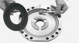
155 ASSEMBLY ASSEMBLY FIGURE 16: Fit o-rings (4)(28)(27)(5)(6) onto the piston (3). Lubricate the piston and the o-rings and install the unit into the cylinder (7) FIGURE 17: Using a plastic hammer, insert the piston (3) into the cylinder (7). Lightly hammer all around the edge in an alternate sequence. 7 FIGURE 19: Using a plastic hammer, insert the piston (10) into the cylinder (7). Lightly hammer all around the edge in an alternate sequence FIGURE 20: Apply grease and position the Belleville washers (2) and engage the cylinder (7). FIGURE 18: Fit o-rings (9) and (8) onto the piston (10). Lubricate the piston and the o-rings and install the unit into the cylinder (7). Check the sense of direction of washers (7) and relative centering. 155
 and engage")
 and")


156 ASSEMBLY 1 2 FIGURE 21: Apply grease and position the Belleville washers (2) and engage the cylinder (1). Check the sense of direction of washers (2) and relative centering. FIGURE 24: Lock the cylinder N m FIGURE 25: Tightening the studs with a torque wrench set to a torque of N m. FIGURE 22: Check quality and position of the cylinder's o- ring. 7 7 FIGURE 26: Fill with ATF oil. For details see ADJUSTMENT AND CHECKS p. 14 FIGURE 23: Position the Belleville washers (2) and engage the cylinder (7). Check the sense of direction of washers (2) and relative centering. 156

(13)")

.")


157 ASSEMBLY FIGURE 27: Connect an external pump to the negative brake and introduce pressure to bar. FIGURE 30: Fit the reversal springs (12)(13) on the piston (11) N m FIGURE 28: Insert the stroke automatic regulation springs (19); place them in line with the piston (11). FIGURE 31: Apply LOCTITE 270 to the thread of the pistion adjustment nut. Tighten with torque wrench setting of N m Y FIGURE 29: Insert the intermediate disk (11). FIGURE 32: Y=brake gap 0,75mm 1,00mm 1,25mm 1,50mm Depending on axle configuration. 157


158 ASSEMBLY 5-7 N m FIGURE 33: Fit the pin screws making sure that they are all of the same color. Apply Loctite 270 to the thread. Torque wrench setting: 5-7 N m. FIGURE 36: Arm fix quote = 68 mm S 24 FIGURE 37: S = 68 mm - ( x + y + v ) = Thickness of shims to insert under the shim washer. FIGURE 34: Take the measurement from the surface of the intermediate disk to the cover sealing surface with 30 bar of pressure introduced. EXAMPLE: 25.4 mm S 24 FIGURE 35: Put the brake disc pack including the shim under a press, load with 1000 kg and take the measure V. EXAMPLE: V = 40 mm 158


159 ASSEMBLY B 14 A B FIGURE 38: Slightly lubricate the braking disks (14) and fit them in the arm following the correct sequence; orient them so that the oil circulation holes and the marks B are lined up. When installing the steel discs, the slot corresponding to the oil level cap should always be kept free. FIGURE 40: Torque wrench setting: A = 200 N m B = 283 N m Tighten using the criss-cross method. FIGURE 39: Check integrity and position of the arm's o-ring; install the complete arm. To assist axle shaft centering, slightly move the wheel hub. 159
160 ASSEMBLY 160
161 INCORPORATED REDUCTION GEAR AND PINION 602 EXPLODED VIEW


 together")
 and")
")
162 DISASSEMBLY DISASSEMBLY 1 5 FIGURE 1: The figure shows the axle with incorporated reduction gear with Mechanic flanges; disassembly and assembly procedures also apply to DIN flanges. FIGURE 4: Remove the upper flange (1) together with dust ring (5) FIGURE 5: Remove the snap ring (6) and discard it. FIGURE 2: Loosen the check nuts on upper (1) and lower (2) flange FIGURE 6: Remove the lower flange (2). FIGURE 3: Draw out nuts (3) and o-rings (4). 162
 from cover (9).")
.")
 from the body of")
 and remove any sealant left.")
163 DISASSEMBLY FIGURE 7: Remove check screws (7), (8) and relative washers (10) from cover (9). FIGURE 10: Lightly tap with a hammer to disengage cover (9) from upper gear (12) FIGURE 8: In turn, insert a punch in the slots provided and, tapping lightly with a hammer, separate the cover (9) from the body of the reduction gear (11). FIGURE 11: Draw out cover (9) and remove any sealant left FIGURE 12: Remove lower gear (13). FIGURE 9: Insert two levers in the provided slots and move the cover (9) away from the body of the reduction gear (11). 163
 from cover (9) and discard it. Write down direction of installation.")
 from gear assembly (12).")
164 DISASSEMBLY FIGURE 13: Remove upper gear assembly (12) complete with bearings (14). FIGURE 16: Remove outer bearing (14) and spacer (16) FIGURE 14: Using a puller, remove snap ring (15) from cover (9) and discard it. Write down direction of installation. FIGURE 17: Disjoin from the steering case the steering bar located by the side of the intermediate cover (17). Remove the complete arm. For details, see CHECKING WEAR AND REPLACING THE BRAKING DISCS p FIGURE 15: Remove inner bearing (14) from gear assembly (12). FIGURE 18: Remove the intermediate cover (17) and the whole differential unit (18). For details, see DIFFERENTIAL UNIT p

, spacer (22) and distance")


 on the pinion (20).")

165 DISASSEMBLY FIGURE 19: Heat the ring nut (19) at approx. 80 C. FIGURE 22: Using a puller, extract pinion (20) complete with inner bearing (21), spacer (22) and distance washers. T2 9 The thrust blocks of the bearings remain in the central body (11). T1 T3 0 FIGURE 20: Engage special wrench T1 (See drawing T1 p. 169) on the ring nut (19) and apply bar-hold T2 (See drawing T2 p. 170) on the pinion (20). 20 FIGURE 23: Remove the complete pinion (20). Carefully check and note direction of installation of spacer FIGURE 21: Remove ring nut (19). FIGURE 24: Using a punch and a hammer, extract the snap ring (25). Note direction of installation of snap ring (24). 165
 (See BEVEL PI- NION p. 67). Using tool T3 (See drawing T3 p.")
 and T4B (See drawing T4 p. 172) connected to a press, insert the complete pinion assembly (20).")
. FIGURE 28: Apply Loctite 242 to the thread of the pinion and screw the ring nut (19).")
 following the appropriate procedure (See BEVEL PINION p. 67) and check that torque is 170-220Ncm.")
166 ASSEMBLY ASSEMBLY T3 T7 FIGURE 25: Find the value of the distance washers (23) and (24) and insert the thrust blocks of the conical bearing of the pinion into the body of the reduction gear (11) (See BEVEL PI- NION p. 67). Using tool T3 (See drawing T3 p. 171) insert the snap ring (25) previously lubricated with grease. FIGURE 27: With tools T4C (See drawing T4 p. 172), T4D (See drawing T4 p. 172) and T4B (See drawing T4 p. 172) connected to a press, insert the complete pinion assembly (20). T29 T1 T FIGURE 26: Assemble the pinion assembly as shown in the picture, checking that spacer (22) is correctly oriented. Apply grease to the outer surface of the spacer (22). FIGURE 28: Apply Loctite 242 to the thread of the pinion and screw the ring nut (19). Engage special wrench T1 (See drawing T1 p. 169) on the ring nut and apply bar-hold T2 (See drawing T2 p. 170) to the pinion (20). Tighten the ring nut (19) following the appropriate procedure (See BEVEL PINION p. 67) and check that torque is Ncm FIGURE 29: Re-install the differential unit (18) and the intermediate cover (17). 166
 and (6); position the snap rings in the cover (9) using tool T5 (See drawing T5 p. 173).")
 onto the pinion (20). 14 12 12 11 FIGURE 31: Using a press, fit the bearings (14) and the spacer (16) on the upper gear (12).")
167 ASSEMBLY CAUTION If the crown has been replaced, reinstate clearances. For details, see DIFFERENTIAL UNIT p. 61. T32 T5 T5 T FIGURE 32: Grease snap rings (15) and (6); position the snap rings in the cover (9) using tool T5 (See drawing T5 p. 173). FIGURE 30: Re-install the complete arm checking flatness and blocking the arm by keeping to the appropriate procedures illustrated in section CHECKING WEAR AND REPLACING THE BRAKING DISCS p. 19. Also connect the steering bar FIGURE 33: Fit the lower gear (13) onto the pinion (20) FIGURE 31: Using a press, fit the bearings (14) and the spacer (16) on the upper gear (12). CAUTION The di stance piece (16) must be positioned between the outer bearing and the gear. FIGURE 34: Insert the upper gear unit (12) into the body of the reduction gear (11). 167
 and (15); fit cover (9) and set cover (if necessary) by lightly tapping with a plastic hammer. FIGURE 38: Apply tool T6A (See drawing T6 p.")
 with screws (7) and (8) and relative washers (10). Tighten using the criss-cross method. Torque wrench setting: 82-91 N m.")
168 ASSEMBLY T6A (T6B) T20A (T20B ) 2 3 FIGURE 35: Apply Loctite 510 to the locking surface of the body of the reduction gear (11). Lubricate snap rings (6) and (15); fit cover (9) and set cover (if necessary) by lightly tapping with a plastic hammer. FIGURE 38: Apply tool T6A (See drawing T6 p. 174) (or T6B) to flanges (1) and (2) and tighten nuts (3) using a dynamometric wrench. Torque wrench setting: N m FIGURE 36: Block cover (9) with screws (7) and (8) and relative washers (10). Tighten using the criss-cross method. Torque wrench setting: N m FIGURE 37: Fit the upper (1) and lower (2) flanges. Apply Loctite 242 to the threaded portion of pinion (20) and upper gear (12). Fit o-rings (4) and nuts (3). 168
Section 7 REAR END MAINTENANCE AND REPAIR
 TABLE OF CONTENTS PAGE INTRODUCTION...7-2 MAINTENANCE AND LUBRICANT...7-3 DEFINITION OF VIEW POINTS...7-3 DATA PLATE...7-3 MAINTENANCE POINTS...7-4 MAINTENANCE INTERVALS...7-5 ADJUSTMENT AND CHECKS...7-5
Service Manual. Axle 213
 Service Manual Axle 213 ASM-0026E June 2012 CONTENTS INTRODUCTION... 5 SPECIFICATIONS...6 DEFINITION OF VIEWPOINTS... 6 DATA PLATE... 6 CONVERSION TABLES... 7 TORQUE SPECIFICATIONS... 8 COARSE PITCH...
LIFT TRUCK SERIES: G35S-2 G40S-2 G45S-2 G40SC-2 G45SC-2 G50SC-2. November 15, 2000 CODE 3150 LT3150-L0 SUBJECT: NEW DRIVE AXLE
 LIFT TRUCK SERIES: G35S-2 G40S-2 G45S-2 G40SC-2 G45SC-2 G50SC-2 November 15, 2000 CODE 3150 LT3150-L0 SUBJECT: NEW DRIVE AXLE A new drive axle has been introduced in the above model lift trucks. The purpose
DRIVE AXLE Nissan 240SX DESCRIPTION & OPERATION AXLE RATIO & IDENTIFICATION AXLE SHAFT & BEARING R & I DRIVE SHAFT R & I
 DRIVE AXLE 1990 Nissan 240SX 1990 DRIVE AXLES Rear Axle - R200 240SX, 300ZX DESCRIPTION & OPERATION The axle assembly is a hypoid type gear with integral carrier housing. The pinion bearing preload adjustment
1984 Dodge W250 PICKUP
 1984 Dodge W250 PICKUP Submodel: Engine Type: V8 Liters: 5.2 Fuel Delivery: CARB Fuel: GAS Dana 44 MODELS THROUGH 1984 2. Raise and safely support the vehicle, then remove the wheel hub and bearings as
TROUBLESHOOTING SPECIAL TOOL ASSEMBLY AND ADJUSTMENT
 1 INDEX Models FD, FE, FF and SG REAR AXLE 10-1 10-108E-07 CHAPTER 10 REAR AXLE Models FD, FE, FF and SG TROUBLESHOOTING...10-2 10 SPECIAL TOOL...10-3 WHEEL HUB AND RELATED PARTS DISASSEMBLY...10-7 INSPECTION...10-9
DRIVE AXLE - INTEGRAL HOUSING
 DRIVE AXLE - INTEGRAL HOUSING 1993 Toyota Celica 1993 DRIVE AXLES Toyota Differentials & Axle Shafts - Integral Housing Toyota; Celica All-Trac DESCRIPTION Drive axle assembly is a hypoid type with integral
MAINTENANCE MANUAL DP-265
 MAINTENANCE MANUAL DP-265 Drive Gears Sisu Axles, Inc. Autotehtaantie 1 P.O. Box 189 FIN-13101 Hämeenlinna Finland Phone int + 358 204 55 2999 Fax int + 358 204 55 2900 DP265DG.PDF (2/2003) k Table of
DIFFERENTIALS & AXLE SHAFTS
 DIFFERENTIALS & AXLE SHAFTS 2001 Chevrolet Camaro 2000-01 DRIVE AXLES General Motors Differentials & Axle Shafts Chevrolet; Camaro Pontiac; Firebird DESCRIPTION & OPERATION Drive axle is a semi-floating,
2005 Toyota RAV AUTOMATIC TRANSMISSIONS U240E & U241E Overhaul
 2001-05 AUTOMATIC TRANSMISSIONS U240E & U241E Overhaul APPLICATION CAUTION: Flush oil cooler and oil cooler lines prior to transaxle installation. Oil cooling system contamination may cause premature transaxle
Steer Axles. Spicer. Service Manual. AXSM-0070 November Front Drive Steer Axle Model 60
 Spicer Steer Axles Service Manual AXSM-0070 November 2017 Front Drive Steer Axle Model 60 General Information The description and specifications contained in this service publication are current at the
1. General Description
 1. General Description A: SPECIFICATIONS 1. Type Transmission gear ratio Front reduction gear Rear reduction gear 2. TRANSMISSION GEAR OIL Recommended oil Final Transfer 5-forward speeds with synchromesh
DRIVE AXLE Volvo 960 DESCRIPTION & OPERATION AXLE IDENTIFICATION DRIVE AXLES Volvo Differentials & Axle Shafts
 DRIVE AXLE 1994 Volvo 960 1994 DRIVE AXLES Volvo Differentials & Axle Shafts 960 DESCRIPTION & OPERATION All 960 station wagon models use type 1041 rear axle assembly. All 960 4-door models use type 1045
Off-Highway Axle Planetary Wheel Ends
 Maintenance Manual MM-1189 Off-Highway Axle Planetary Wheel Ends Revised 06-16 Service Notes About This Manual This manual provides service and repair procedures for planetary wheel ends on off-highway
Brake System H TX, H2.0TXS [B475]; H TX [B466] Safety Precautions Maintenance and Repair
![Brake System H TX, H2.0TXS [B475]; H TX [B466] Safety Precautions Maintenance and Repair](/thumbs/86/93834005.jpg "Brake System H TX, H2.0TXS [B475]; H TX [B466] Safety Precautions Maintenance and Repair") HMM180001 Brake System H1.5-1.8TX, H2.0TXS [B475]; H2.5-3.5TX [B466] Safety Precautions Maintenance and Repair When lifting parts or assemblies, make sure all slings, chains, or cables are correctly fastened,
HMM180001 Brake System H1.5-1.8TX, H2.0TXS [B475]; H2.5-3.5TX [B466] Safety Precautions Maintenance and Repair When lifting parts or assemblies, make sure all slings, chains, or cables are correctly fastened,
REMOVAL & INSTALLATION
 REMOVAL & INSTALLATION AXLE SHAFTS & BEARINGS Removal CAUTION: Failure to turn off air suspension power before raising vehicle may result in unexpected inflation or deflation of air springs. DO NOT reconnect
SISU DP-330 DRIVE GEAR. Maintenance Manual
 SISU DP-330 DRIVE GEAR Maintenance Manual Sisu Axles, Inc. Autotehtaantie 1 PO Box 189 Fin-13101 Hameenlinna Finland Phone +358 204 55 2999 Fax +358 204 55 2900 DP330DG.PDF (3/2007) TABLE OF CONTENTS
DRIVE AXLE - 4WD MODELS WITH INTEGRAL HOUSING
 DRIVE AXLE - 4WD MODELS WITH INTEGRAL HOUSING 1988 Toyota Celica DRIVE AXLES Toyota Integral Housing Celica (Rear) DESCRIPTION housing. Drive axle assembly is hypoid type with integral carrier AXLE RATIO
1988 Chevrolet Pickup V SUSPENSION - FRONT (4WD)' 'Front Suspension - "V" Series 1988 SUSPENSION - FRONT (4WD) Front Suspension - "V" Series
' 'Front Suspension - V Series 1988 SUSPENSION - FRONT (4WD) Front Suspension - V Series") 1988 SUSPENSION - FRONT (4WD) Front Suspension - "V" Series DESCRIPTION NOTE: Vehicle serial numbers used in this article has been abbreviated for common reference to Chevrolet and GMC models. Chevrolet
1988 SUSPENSION - FRONT (4WD) Front Suspension - "V" Series DESCRIPTION NOTE: Vehicle serial numbers used in this article has been abbreviated for common reference to Chevrolet and GMC models. Chevrolet
SECTION 3A FRONT DRIVE AXLE TABLE OF CONTENTS SPECIFICATIONS GENERAL SPECIFICATIONS. Description Drive Shaft Type. CV Joint Axle Housing Type
 SECTION 3A FRONT DRIVE AXLE TABLE OF CONTENTS Specifications........................ 3A-1 General Specifications.................. 3A-1 Fastener Tightening Specifications......... 3A-2 Component Locator...................
REAR AXLE Click on the applicable bookmark to selected the required model year
 REAR AXLE 27-1 REAR AXLE CONTENTS GENERAL INFORMATION.................. 2 SERVICE SPECIFICATIONS................. 3 LUBRICANTS.............................. 3 SEALANTS AND ADHESIVES.............. 4 SPECIAL
-7 I Remove the brake shoe return springs.
 REAR AXLE 9-A.REAR AXLE SHAFT... 9: 1 9.A.1. Removing Rear Axle Shaft... 9 : 1 9.A.2 Disassembling Rear Axle Shaft... 9 : 2 9.A.3. Inspecting Rear Axle Shaft and Bearing... 9 : 3 9.A-4 Assembling Rear
Amarillo PUMP DRIVES (250 HP THROUGH 350 HP) INSTRUCTIONS FOR REPAIRING MODELS 250, 300, and 350
 INSTRUCTIONS FOR REPAIRING MODELS 250, 300, and 350") Amarillo PUMP DRIVES (250 HP THROUGH 350 HP) INSTRUCTIONS FOR REPAIRING MODELS 250, 300, and 350 Amarillo Right Angle Pump Drives, if properly installed and maintained, should provide years of service
Amarillo PUMP DRIVES (250 HP THROUGH 350 HP) INSTRUCTIONS FOR REPAIRING MODELS 250, 300, and 350 Amarillo Right Angle Pump Drives, if properly installed and maintained, should provide years of service
TC Series Front Axle. TC Series Front Axle 010-1
 TC Series Front Axle Blue Bird Corporation assumes sole responsibility for ensuring that the information provided herein is accurate to the best of its knowledge at the time of printing. In keeping with
LIMITED SLIP DIFFERENTIAL INSTALLATION
 Installation of the limited slip gear can be done with axle out of car or with car lifted to gain access from underneath. Refer to repair manual for proper lifting instructions if car is to be lifted.
MANUAL TRANSAXLE Return to Main Table of Contents
 MANUAL TRANSAXLE Return to Main Table of Contents GENERAL... 2 MANUAL TRANSAXLE CONTROL... 12 SHIFT LEVER ASSEMBLY... 14 MANUAL TRANSAXLE... 15 MANUAL TRANSAXLE ASSEMBLY... 17 FIFTH SPEED SYNCHRONIZER
Amboid Rear Differential Carrier
 Maintenance Manual MM-0250 Amboid Rear Differential Carrier Rear/Rear Carrier on MT-40-143MA-N Tandem Drive Axles Revised 09-05 Service Notes About This Manual This manual provides instructions for the
TO INDEX DIFFERENTIAL FRONT DIFFERENTIAL CARRIER OIL SEAL (4WD) FRONT DIFFERENTIAL CARRIER ASSEMBLY (4WD) REAR DIFFERENTIAL CARRIER OIL SEAL
 FRONT DIFFERENTIAL CARRIER ASSEMBLY (4WD) REAR DIFFERENTIAL CARRIER OIL SEAL") TO INDEX DRIVE LINE / AXLE DIFFERENTIAL DIFFERENTIAL SYSTEM PRECAUTIONS.............................................. OPERATION CHECK......................................... PROBLEM SYMPTOMS TABLE.................................
TO INDEX DRIVE LINE / AXLE DIFFERENTIAL DIFFERENTIAL SYSTEM PRECAUTIONS.............................................. OPERATION CHECK......................................... PROBLEM SYMPTOMS TABLE.................................
AUTOMATIC TRANSAXLE AUTOMATIC TRANSAXLE SYSTEM... COMPONENT PARTS...
 SYSTEM....... COMPONENT PARTS.................... OIL PUMP.............................. DIRECT CLUTCH........................ FORWARD CLUTCH..................... SECOND BRAKE........................ UNDERDRIVE
SECTION ZF FRONT AXLE
 04-101.01/ 1 2011JA14 SECTION 04-101.01 6 3 5 1 2 9 1. Upper radius rod 2. Lower radius rod 3. Caliper 4. BRAKE Disk 5. Pneumatic connector 6. Hub 7. steering knuckle 8. Grease Fitting 9. Pneumatic connector
SERVICE MANUAL STEERING AND RIGID DRIVE AXLES SERIES 068. Date Revision Description Owner 06/10/ Document emission PM
 SERVICE MANUAL STEERING AND RIGID DRIVE AXLES SERIES 068 Date Revision Description Owner 06/10/09 1.0 Document emission PM COMER INDUSTRIES Axles & Wheel Drive Units Via Magellano, 37-42046 Reggiolo (RE)
SERVICE MANUAL L130B / L4130 Series Logstacker Drive Axle With Bolt-On Stub End Retainer
 SERVICE MANUAL L130B / L4130 Series Logstacker Drive Axle With Bolt-On Stub End Retainer Page 1 Allied Form #80-930 Rev 07/2009 SERVICE MANUAL LOG STACKER DA202 DRIVE AXLE TABLE OF CONTENTS PROCEDURE FOR
REAR AXLE Click on the applicable bookmark to selected the required model year
 REAR AXLE 27-2 REAR AXLE General Information GENERAL INFORMATION 27100010118 The rear axle is a banjo-type semi-floating type. The axle shaft bearings are: *Single taper bearings for vehicles without
4-50 BRAKES AND STEERING CLUTCHES
 4-50 BRAKES AND STEERING CLUTCHES Disassembly of bevel gear crown WARNING Lift and handle all heavy items with a hoist of appropriate capacity. Make sure that all parts are held by appropriate slings and
1. General Description
 1. General Description A: SPECIFICATION 1. MANUAL TRANSMISSION AND FRONT DIFFERENTIAL Type Transmission gear ratio Front reduction gear Rear reduction gear Front differential Center differential Final
Single reduction Differential Carrier Series 7 - MS15 - MS16 - MS17 - MR15 Revised April 2003
 an ArvinMeritor brand Maintenance manual no. MM-0140 Single reduction Differential Carrier Series 7 - MS15 - MS16 - MS17 - MR15 Revised April 2003 Table of contents pg. 05 Section 1: Introduction 06 Description
BRAKE E
 8-1 GENERAL...8-2 SPECIFICATIONS...8-6 COMPONENTS...8-7 FRONT BRAKE...8-12 DISASSEMBLY INSPECTION REASSEMBLY (Pn1, Cu2 3 TON SERIES)...8-12 DISASSEMBLY INSPECTION REASSEMBLY (Pn2 3 TON SERIES)...8-17 BRAKE
REAR DIFFERENTIAL LOCATION INDEX
 2007 DRIVELINE/AXLES Differential - MX-5 Miata REAR DIFFERENTIAL LOCATION INDEX Fig. 1: Identifying Location Of Rear Differential Components DIFFERENTIAL OIL INSPECTION 1. Park the vehicle on level ground
Rear Axle Single-Reduction Carrier
 Revised 08-0 Rear Axle Single-Reduction Carrier Model MS-3 Maintenance Manual MM-030 Service Notes Service Notes Notes About This Manual This manual provides instructions for Meritor s model MS-3 single-reduction
A/C COMPRESSOR SERVICING Article Text 1991 Saab 9000 For Copyright 1997 Mitchell International Friday, October 15, :22PM
 Article Text ARTICLE BEGINNING 1991 GENERAL SERVICING Compressor Service * PLEASE READ THIS FIRST * CAUTION: When discharging air conditioning system, use only approved refrigerant recovery/recycling equipment.
REEDSTER 125cc. versions: F1 - F2 - F3 - F4 OVERHAULING MANUAL
 REEDSTER 125cc versions: F1 - F2 - F3 - F4 OVERHAULING MANUAL 07/11/07 21/01/2009 1 INDEX Page 1. - REEDSTER 125cc ENGINE DISASSEMBLY 1 2. - CRANKSHAFT DISASSEMBLY / ASSEMBLY 13 2.1 - CRANKSHAFT DISASSEMBLY
1999 F-150/250 Workshop Manual
 Page 1 of 30 SECTION 205-03: Front Drive Axle/Differential Ford 8.8-Inch Ring Gear 1999 F-150/250 Workshop Manual DISASSEMBLY AND ASSEMBLY Procedure revision date: 01/08/2003 Axle Front Drive Special Tool(s)
PROPELLER SHAFT & DIFFERENTIAL CARRIER SECTIONPD CONTENTS
 PROPELLER SHAFT & DIFFERENTIAL CARRIER SECTIONPD CONTENTS PREPARATION...2 PROPELLER SHAFT...5 On-Vehicle Service...6 Removal and Installation...7 Inspection...7 Disassembly...7 Assembly...8 ON-VEHICLE
 AUTOGARD SERIES 820 TORQUE LIMITER Installation and Maintenance Manual DB0009 Issue 11 21 Feb 2017 British Autogard Ltd 2 Wilkinson Rd., Love Lane Industrial Estate, Cirencester, Glos., GL7 1YT UK Tel.
SISU MP-330 DRIVE GEAR. Maintenance Manual
 SISU MP-330 DRIVE GEAR Maintenance Manual Sisu Axles, Inc. Autotehtaantie 1 PO Box 189 Fin-13101 Hameenlinna Finland Phone +358 204 55 2999 Fax +358 204 55 2900 MP330DG.PDF (4/2007) TABLE OF CONTENTS
DISASSEMBLY AND ASSEMBLY
 205-03-1 Front Drive Axle/Differential Ford 8.8-Inch Ring Gear 205-03-1 DISASSEMBLY AND ASSEMBLY Axle Front Drive Special Tool(s) 2-Jaw Puller 205-D072 (D97L-4221-A) Special Tool(s) Carrier Bearing Replacer
Installation and Maintenance Instructions JSE MAEAD Extruder Clutch. World Leader in Modular Torque Limiters
 World Leader in Modular Torque Limiters Installation and Maintenance Instructions JSE.5-0104MAEAD Extruder Clutch 1304 Twin Oaks Street Wichita Falls, Texas 76302 (940) 723-7800 Fax: (940) 723-7888 E-mail:
BRAKE SYSTEM Nissan 240SX DESCRIPTION BRAKE BLEEDING * PLEASE READ FIRST * BLEEDING PROCEDURES ADJUSTMENTS BRAKE PEDAL HEIGHT SPECS TABLE
 BRAKE SYSTEM 1990 Nissan 240SX 1990 BRAKE SYSTEMS Nissan Disc & Drum Axxess, Maxima, Pathfinder, Pickup, Pulsar NX, Sentra, Stanza, 240SX, 300ZX DESCRIPTION All brake systems are hydraulically operated
 DRUM BRAKE RIMS Periodic inspection of drum brake rims is necessary to determine indications of uneven or excessive wear. In general, brake rim failures other that regular wear are caused by brake linings
AUTOMATIC TRANSMISSIONS Mitsubishi F3A20 Series TRANSMISSION APPLICATION TABLE
 Article Text ARTICLE BEGINNING AUTOMATIC TRANSMISSIONS Mitsubishi F3A20 Series APPLICATION TRANSMISSION APPLICATION TABLE Vehicle Application Transmission Model Colt 3-Speed (1990-94)... F3A21 Colt Vista
Sisu S-Cam Drum Brakes
 Sisu S-Cam Drum Brakes (For hub reduction rear axles since 1992) Maintenance Manual Sisu Axles, Inc. Autotehtaantie 1 P.O. Box 189 FIN-13101 Hämeenlinna Finland Phone int + 358 204 55 2999 Fax int + 358
Input Adjusting Ring Leak Repair Procedure for Meritor MT-14X Series Forward Differential Carriers
 Revised 01-16 Technical Bulletin Input Adjusting Ring Leak Repair Procedure for Meritor MT-14X Series Forward Differential Carriers Revised 1 Technical 01- Bulletin 16 Hazard Alert Messages Read and observe
This file is available for free download at
 This file is available for free download at http://www.iluvmyrx7.com This file is fully text-searchable select Edit and Find and type in what you re looking for. This file is intended more for online viewing
MAINTENANCE MANUAL. Differential Axle MS Edition october/11
 MAINTENANCE MANUAL Differential Axle MS - 113 Edition october/11 Index 1 - Notes to Technical Assistance... 03 2 - Exploded View MS-113... 04 3 - Exploded View MS-113 Plus... 05 4 - Introduction... 06
TECHNICAL BULLETIN. TP Issued Servicing Rockwell s TB Series Trailer Axles with Unitized Hub Assemblies
 TECHNICAL BULLETIN TP-96175 Issued 12-96 Servicing Rockwell s TB Series Trailer Axles with Unitized Hub Assemblies TB Series Trailer Axles Introduction Rockwell s TB series trailer axle features a permanently
SERVICE INFORMATION 11-1 FRONT WHEEL/SUSPENSION/ STEERING XL FRONT WHEEL 11 7 FORK STEERING STEM 11 18
 XL200 11. FRONT WHEEL/SUSPENSION/ STEERING SERVICE INFORMATION 11 1 TROUBLESHOOTING 11 2 HANDLEBAR 11 3 FRONT WHEEL 11 7 FORK 11 11 STEERING STEM 11 18 SERVICE INFORMATION GENERAL A contaminated brake
SECTION 3D REAR AXLE TABLE OF CONTENTS
 SECTION 3D REAR AXLE TABLE OF CONTENTS General Description and Operation... 3D-2 Specifications... 3D-2 Fastener Tightening Specifications... 3D-2 Diagnostic Information and Procedures... 3D-3 Component
SUSPENSION 2-1 SUSPENSION TABLE OF CONTENTS
 DN SUSPENSION 2-1 SUSPENSION TABLE OF CONTENTS page ALIGNMENT... 1 FRONT SUSPENSION - 4x2... 6 page FRONT SUSPENSION - 4x4... 14 REAR SUSPENSION... 23 ALIGNMENT TABLE OF CONTENTS page AND OPERATION WHEEL
KAM Ring and Pinion fitting instructions (Mechanical knowledge necessary, these instructions are intended as a guide)
") KAM Ring and Pinion fitting instructions (Mechanical knowledge necessary, these instructions are intended as a guide) DISMANTLE It is essential that differential components are marked in their original
KAM Ring and Pinion fitting instructions (Mechanical knowledge necessary, these instructions are intended as a guide) DISMANTLE It is essential that differential components are marked in their original
615 Service Manual SERVICE MANUAL. 615 Series Axle
 SERVICE MANUAL 615 Series Axle Issue 1 - February 2002 CONTENT: 1 INTRODUCTION... Page - 1-2 GENERAL DESCRIPTION... Page - 1-3 IDENTIFICATION... Page - 1-4 GENERAL SERVICE INFORMATION... 4.1 Routine Maintenance...
M Ring and Pinion Installation
 !!! PLEASE READ ALL OF THE FOLLOWING INSTRUCTIONS CAREFULLY PRIOR TO INSTALLATION. Axle Shaft Removal (1994-2012 Mustang typical) STEP 1: STEP 2: Remove the 10 differential housing cover bolts and drain
FRONT AXLE 26-1 CONTENTS GENERAL INFORMATION... 2 HUB AND KNUCKLE ASSEMBLY SERVICE SPECIFICATIONS... 4 DRIVE SHAFT LUBRICANTS...
 26-1 FRONT AXLE CONTENTS GENERAL INFORMATION.................. 2 SERVICE SPECIFICATIONS................. 4 LUBRICANTS.............................. 4 SEALANTS AND ADHESIVES.............. 5 SPECIAL TOOLS...........................
BRAKE SYSTEM Toyota Celica DESCRIPTION DRUM BRAKES ADJUSTMENTS BRAKE PEDAL HEIGHT ADJUSTMENTS BRAKE PEDAL FREE PLAY ADJUSTMENTS
 BRAKE SYSTEM 1988 Toyota Celica 1988-89 BRAKES Toyota Celica, Corolla, MR2, Tercel DESCRIPTION The hydraulic brake system uses a tandem master cylinder with a vacuum power assist servo. MR2 and some Celica
Maintenance Manual MM-0194 Single reduction leading axle carrier for tandem axle series MD61. Revised September 2017
 Maintenance Manual MM-0194 Single reduction leading axle carrier for tandem axle series MD61 Revised September 2017 Service Notes Before You Begin This publication provides installation and maintenance
Installation and Maintenance Instructions JSE1-0128MAEAD Extruder Clutch. World Leader in Modular Torque Limiters
 World Leader in Modular Torque Limiters Installation and Maintenance Instructions JSE1-0128MAEAD Extruder Clutch 1304 Twin Oaks Street Wichita Falls, Texas 76302 (940) 723-7800 Fax: (940) 723-7888 E-mail:
Maintenance Manual FP-330 Drive Gear
 Maintenance Manual FP-330 Drive Gear Sisu Axles, Inc. Autotehtaantie 1 P.O. Box 189 FIN-13101 Hämeenlinna Finland Phone int + 358 204 55 2999 Fax int + 358 204 55 2900 FP330DG 2/2008 Maintenance Manual
Transmission Overhaul Procedures-Bench Service
 How to Assemble the Lower Reverse Idler Gear Assembly Special Instructions In 1996 Eaton changed the reverse idler system design. In the nut design, the reverse idler bearing was lubricated through a hole
4. Rear Differential REAR DIFFERENTIAL
 DIFFERENTIALS 4. Rear Differential A: REMOVAL 1) Set the vehicle on a lift. 2) Disconnect the ground cable from battery. 3) Move the select lever or gear shift lever to N. 4) Release the parking brake.
Gear Products Inc N. 161st E. Ave. Tulsa, OK Phone (918) Fax (918)
 Fax (918)") SERVICE MANUAL Disassembly & Assembly Procedures Worm Gear Swing Drive 003 Series Gear Products Inc. 1111 N. 161st E. Ave. Tulsa, OK 74116 Phone (918) 234-3044 Fax (918) 234-3455 Worm Gear Swing Drive
SERVICE MANUAL Disassembly & Assembly Procedures Worm Gear Swing Drive 003 Series Gear Products Inc. 1111 N. 161st E. Ave. Tulsa, OK 74116 Phone (918) 234-3044 Fax (918) 234-3455 Worm Gear Swing Drive
Pneumatic Angle Grinder also for Underwater Use Type
 M a s c h i n e n f a b r i k G m b H Pneumatic Angle Grinder also for Underwater Use Type 1 4311 0050 Illustration can differ from the original Repair Manual and Spare Parts List Compiled: 22.06.11 143110050_Inst_en_Version_00
Installation Instructions
 Preparing your vehicle to install your brake system upgrade 1. Rack the vehicle. 2. If you don t have a rack, then you must take extra safety precautions. 3. Choose a firmly packed and level ground to
SERVICE MANUAL. 915 Series Axle
 SERVICE MANUAL 915 Series Axle Issue 1 September 2003 CONTENT: 1 INTRODUCTION Page 3-2 GENERAL DESCRIPTION Page 3-3 IDENTIFICATION Page 3-4 GENERAL SERVICE INFORMATION Page 5 -.1 4.1 Routine Maintenance
REAR FINAL DRIVE SECTION RFD CONTENTS D DRIVELINE/AXLE RFD-1 RFD
 REAR FINAL DRIVE D DRIVELINE/AXLE SECTION RFD A REAR FINAL DRIVE B C RFD CONTENTS E PRECAUTIONS... 2 Precautions... 2 PREPARATION... 3 Special Service Tools... 3 Commercial Service Tools... 5 NOISE, VIBRATION
Installation and Maintenance Instructions JSE2-0241MAEAD Extruder Clutch. World Leader in Modular Torque Limiters
 World Leader in Modular Torque Limiters Installation and Maintenance Instructions JSE2-0241MAEAD Extruder Clutch 1304 Twin Oaks Street Wichita Falls, Texas 76302 (940) 723-7800 Fax: (940) 723-7888 E-mail:
Overhaul Special Tools Required
 1 of 31 Overhaul - Special Tools Required - Cylinder end seal remover attachment, 07NAD-SR3020A - Pilot collar, 07GAF-PH70100 - Valve seal ring sizing tool, 07NAG-SR3090A - Ball joint boot clip guide,
Model 4360 Teardown and Reassembly Instructions
 Clean the outside surface of the transaxle. Place the shifter in neutral position. Remove detent cover screw (item 3), detent cover (item 4), detent springs (item 5), and detent balls (item 6). Use a magnet
DRIVE AXLES. Differentials & Axle Shafts - Corvette
 DESCRIPTION & OPERATION 1998-99 DRIVE AXLES Differentials & Axle Shafts - Corvette A Getrag 625 model differential is used on both the automatic and manual transmissions. Differential carrier and case
Maintenance Instructions
 General Note These instructions contain information common to more than one model of Bevel Gear Drive. To simplify reading, similar models have been grouped as follows: GROUP 1 Models 11, 0, 1,, (illustrated),,
GROUNDSMASTER. 52 Recycler. for 120 Traction Unit. Model No & UP. Operator s Manual
 FORM NO. 8-980 Rev A GROUNDSMASTER 5 Recycler for 0 Traction Unit Model No. 077 79000 & UP Operator s Manual IMPORTANT: Read this manual carefully. It contains information about your safety and the safety
SECTION Front Drive Axle/Differential
 205-03-i Front Drive Axle/Differential 205-03-i SECTION 205-03 Front Drive Axle/Differential CONTENTS PAGE Axle... 205-03-2 205-03-2 Front Drive Axle/Differential 205-03-2 Axle Special Tool(s) C-Frame
HYDRAULICS. TX420 & & lower. Hydraulic Tandem Pump Removal. 4. Remove the LH side panel (Fig. 0388).
.") TX420 & 425 240000299 & lower 4. Remove the LH side panel (Fig. 0388). Hydraulic Tandem Pump Removal Note: Cleanliness is a key factor in a successful repair of any hydraulic system. Thoroughly clean all
TX420 & 425 240000299 & lower 4. Remove the LH side panel (Fig. 0388). Hydraulic Tandem Pump Removal Note: Cleanliness is a key factor in a successful repair of any hydraulic system. Thoroughly clean all
215 Service Manual SERVICE MANUAL. 215 Series Axle
 SERVICE MANUAL 215 Series Axle Issue 1 - January 2002 CONTENT: 1 INTRODUCTION... Page - 1-2 GENERAL DESCRIPTION... Page - 1-3 IDENTIFICATION... Page - 1-4 GENERAL SERVICE INFORMATION... 4.1 Routine Maintenance...
Sachs shock manual. ( ) 2 & 4 Stroke RR Enduro. ( ) RS Dual Sport
 2 & 4 Stroke RR Enduro. ( ) RS Dual Sport") Sachs shock manual (2013 2015) 2 & 4 Stroke RR Enduro (2014-2015) RS Dual Sport 1 Introduction The procedures in this manual must take place in a clean environment using professional tools and some specific,
Sachs shock manual (2013 2015) 2 & 4 Stroke RR Enduro (2014-2015) RS Dual Sport 1 Introduction The procedures in this manual must take place in a clean environment using professional tools and some specific,
Premium wheel-end brake products
 Premium wheel-end brake products Spicer Automatic Slack Adjuster Service Manual Self Adjusting Brake Adjuster The description and specifications contained in this service publication are current at the
HGM-E LSHT Wheel Motor Service and Repair Manual
 HGM-E LSHT Wheel Motor Service and Repair Manual BLN-52198 January 2018 Table Of Contents Foreword... 1 How to use this manual... 2 General Instructions... 2 General Description... 2 Tools... 3 Torques...
Single-Reduction Forward Differential Carriers on Tandem and Tridem Axles
 Maintenance Manual 5L Single-Reduction Forward Differential Carriers on Tandem and Tridem Axles Revised 08-15 Service Notes About This Manual This manual provides maintenance and service information for
FRONT AXLE Click on the applicable bookmark to selected the required model year
 FRONT AXLE 26-1 FRONT AXLE CONTENTS GENERAL INFORMATION.................. 2 SERVICE SPECIFICATIONS................. 4 LUBRICANTS.............................. 4 SEALANTS AND ADHESIVES.............. 5 SPECIAL
CLUTCH CONTENTS SERVICE DIAGNOSIS. (a) Worn or damaged disc assembly. (b) Grease or oil on disc facings. (c) Improperly adjusted cover assembly.
 Worn or damaged disc assembly. (b) Grease or oil on disc facings. (c) Improperly adjusted cover assembly.") CLUTCH CONTENTS -GROUP 6 Page CLUTCH HOUSING ALIGNMENT... 6 CLUTCH PEDAL FREE PLAY 1 CLUTCH RELEASE BEARING 5 CLUTCH RELEASE FORK... 5 CLUTCH SERVICING 2 PILOT BUSHING CRANKSHAFT TO TRANSMISSION DRIVE
CLUTCH CONTENTS -GROUP 6 Page CLUTCH HOUSING ALIGNMENT... 6 CLUTCH PEDAL FREE PLAY 1 CLUTCH RELEASE BEARING 5 CLUTCH RELEASE FORK... 5 CLUTCH SERVICING 2 PILOT BUSHING CRANKSHAFT TO TRANSMISSION DRIVE
SECTION 5B MANUAL TRANSMISSION TABLE OF CONTENTS
 SECTION 5B MANUAL TRANSMISSION TABLE OF CONTENTS General Description and Operation... 5B-2 Shift Lever... 5B-2 Transmission Assembly... 5B-2 Specifications... 5B-3 Diagnostic Information and Procedures...
Front mechanical suspensions
 FRONT MECHANICAL SUSPENSIONS 9 PRINT 603.43.351/D Front mechanical suspensions Page DESCRIPTION... 11 ARTICULATED QUADRILATERAL SUSPENSION WITH TRANSVERSE LEAF SPRING... 11 SPECIFICATIONS AND DATA... 12
SECTION 7 - SUSPENSION
 For Arctic Cat Discount Parts Call 606-678-9623 or 606-561-4983 SECTION 7 - SUSPENSION 7 TABLE OF CONTENTS Front and Rear Suspension Assembly Schematics... 7-2 Shock Absorbers... 7-2 Swing Arm... 7-5 Front
TRANSMISSION 6.7 GENERAL HOME. See Figure The transmission is a five-speed constantmesh type housed in an extension of the crankcase.
 TRANSMISSION 6.7 GENERAL See Figure 6-46. The transmission is a five-speed constantmesh type housed in an extension of the crankcase. b06x6x Neutral st Gear Mainshaft Mainshaft 4 5 4 5 Countershaft Out
Single Rear Drive Axles, Rear-Rear Tandem Drive Axles and Front Drive Steer Axles Revised 02-18
 Maintenance Manual 5A Single-Reduction Differential Carriers Single Rear Drive Axles, Rear-Rear Tandem Drive Axles and Front Drive Steer Axles Revised 02-18 Service Notes About This Manual This manual
S i. wp U-i >-;t(iw> - r^r? *. - * CHAPTER 5. CHASSIS
 wp U-i >-;t(iw> - r^r? *. - * S i CHAPTER 5. CHASSIS 5-1. FRONT WHEEL 5-2 A. Removal 5-2 B. Front Axle Inspection 5-2 C. Front Wheel Inspection 5-2 D. Brake Shoe Wear Inspection 5-2 E. Brake Drum Inspection
Marzocchi Suspension D-Street 24" D-Street 24" Technical instructions
 Technical instructions Exploded view - D-Street 24" 80 Rif. Code Quantity D-Street 24" 80 - Oil levels Position Oil type Quantity (cc) Right fork leg SAE 7,5-550013 185 Left fork leg SAE 7,5-550013 185
Butterfly Valve Type 57P
 Butterfly Valve Type 57P Contents Lever Type: 50-200 mm (2-8 ) Body Material: CPVC Gear Type: 50-200mm (2-8 ) Body Material: CPVC (1) Be sure to read the following warranty clauses of our product 1 (2)
IN-VEHICLE REPAIR. Differential Bearings. Rear Drive Axle/Differential Ford 7.5-Inch Ring Gear. Special Tool(s)
") 205-02A-1 IN-VEHICLE REPAIR Differential Bearings Special Tool(s) Protector, Drive Pinion Thread 205-460 Special Tool(s) Installer, Differential Shim 205-220 (T85L-4067-AH) 205-02A-1 2-Jaw Puller 205-D072
205-02A-1 IN-VEHICLE REPAIR Differential Bearings Special Tool(s) Protector, Drive Pinion Thread 205-460 Special Tool(s) Installer, Differential Shim 205-220 (T85L-4067-AH) 205-02A-1 2-Jaw Puller 205-D072
Maintenance Instructions. World Leader in Modular Torque Limiters. JSE AEA Extruder Clutch
 World Leader in Modular Torque Limiters PROTECTING EQUIPMENT& MACHINERYYEARSInstallation and Maintenance Instructions JSE.5-0234AEA Extruder Clutch 1304 Twin Oaks Street Wichita Falls, Texas 76302 (940)
SERVICE MANUAL MODEL FRONT CARRIER TYPE
 SPICER AXLE SERVICE MANUAL MODEL FRONT CARRIER TYPE INDEX Page LUBRICATION... 3 SPECIAL SERVICE TOOLS...................................................... 4 AXLE IDENTIFICATION... 5 SHAFT BEARINGS AND
CHASSIS CONTENTS EXTERIOR PARTS 6-1 FRAME COVER 6-2 REAR FRAME COVER 6-4 FRONT WHEEL 6-6 FRONT BRAKE 6-10 HANDLEBARS 6-17 FRONT FORK 6-19
 CHASSIS CONTENTS EXTERIOR PARTS 6- FRAME COVER 6- REAR FRAME COVER 6-4 FRONT WHEEL 6-6 FRONT BRAKE 6-0 HANDLEBARS 6-7 FRONT FORK 6-9 STEERING 6-6 REAR WHEEL 6-3 REAR BRAKE 6-39 6 REAR SHOCK ABSORBER 6-43