PARTAN. Installation Manual LOCKER
|
|
|
- Pearl Gwen Bradford
- 6 years ago
- Views:
Transcription
1 S PARTAN Installation Manual LOCKER


2 Also available from USA Standard Gear: Ring & Pinion Sets Master Overhaul Kits Axles
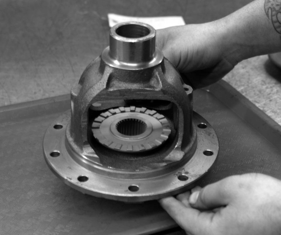
3 Note about your carrier: Before beginning to tear down your differential, please be aware that the Spartan Locker is designed to fit open carriers only. It will not install into any type of limited slip carrier. Preparing the vehicle for installation Take the following steps to prepare your vehicle for installation: Block the vehicle s tires, and place the transmission in neutral Loosen the lug nuts and jack the vehicle up Make sure that the vehicle is securely resting on jack stands Remove the wheels, disconnect the brake lines and emergency brake cables Remove the differential cover (if it is not a third member style differential), and drain the oil Slide out both axles to provide enough clearance to remove the carrier, if necessary. This will require the removal of C-clips, if present Check your ring gear to see if there is enough clearance to remove the cross pin shaft. If there is not enough clearance, please take the steps in the following section to remove your carrier Carrier removal If you are running a low ratio ring & pinion set, such as a 4.88 or 5.13, you may find that your ring gear is too thick to allow for removal of the cross pin shaft. If this is the case, please take the following steps: Using a punch, mark one of the bearing caps so you can remember which side it belongs to. Bearing caps are specific to each side of the housing. This is very important for re-assembly. Figure 1 Check your backlash with a dial indicator and make note of it. You will need to check it again later after re-assembly to make sure everything went back together properly Remove your bearing caps, and pull out your carrier. Some designs have shims outside the races. You must keep track of which side you removed the shims from; they must be returned to the same sides they were removed from. This is also true for the carrier races Remove your ring gear from the carrier 2

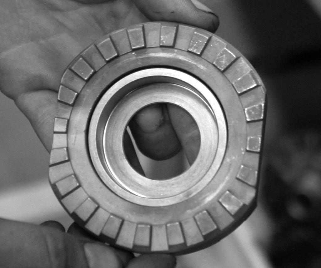
4 Removal of spider gears *Note: If you were able to remove the cross pin shaft without having to remove the ring gear, the following process can be performed with the carrier still in the differential housing. Remove your cross pin shaft retaining pin or bolt Remove the cross pin shaft and inspect it for damage. If it shows excessive wear or damage, purchase a new shaft prior to installation of your Spartan Locker Remove your spider gears and thrust washers. Thoroughly clean the inside of the carrier and dry it. Inspect for any cracks or excessive wear. If the carrier is damaged or worn, replace it prior to installation of your Spartan Locker Figure 1 3
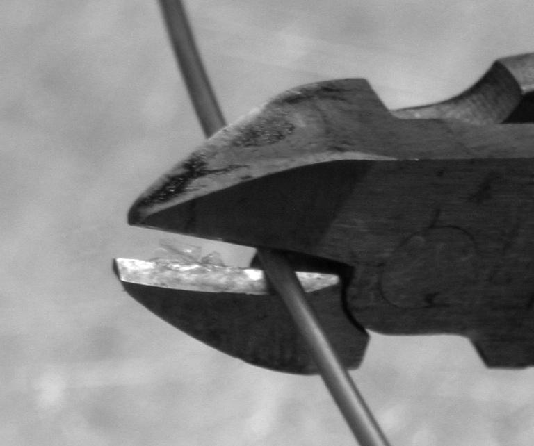
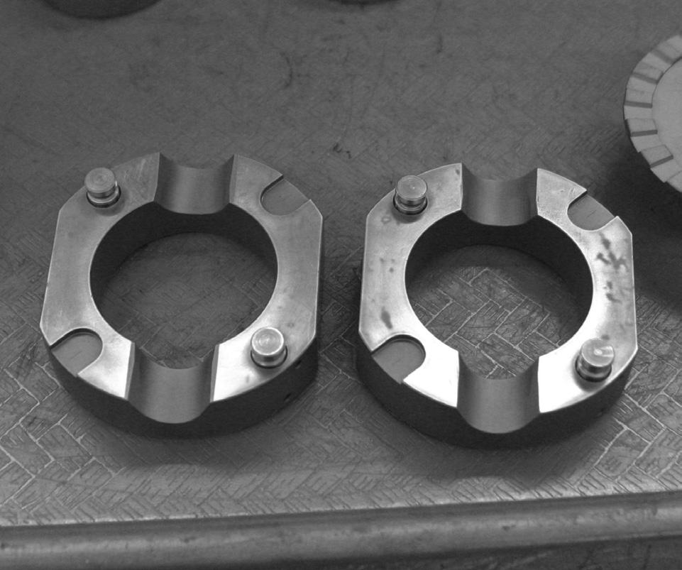
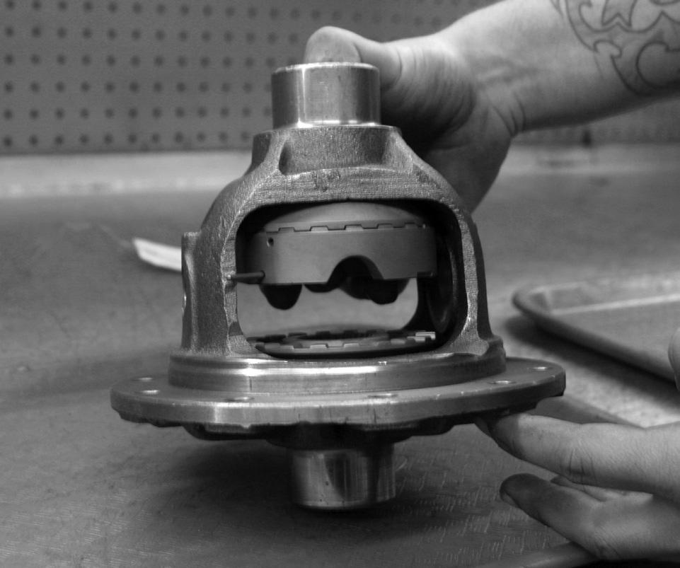
5 Installing your Spartan Locker Place a spring into the hollow end of each of the alignment pins, set aside. Figure 2 Fashion 4 retainer wires from the wire provided, make sure each retainer is long enough to be removed after driver installation with small pliers. Figure 3 & 4 Install the four alignment pin/spring assemblies into the respective driver holes. Figure 5 Push each alignment pin/spring assembly fully down into the driver and insert the retainer wire into retainer wire hole in the driver to hold the alignment pin/spring assembly down Figure 6 Instal side couplers into carrier case Figure 7 Install the spacers into the centers of each driver, Making sure that the open face of the spacer is positioned toward the driver s teeth. Figure 8 Take one of the center drivers, with the spacer placed in it, and install it into the carrier. Figure 9 Rotate the drivers until the alignment pin/spring assemblies line up with corresponding alignment pin seating notches in the opposite driver. Pull the alignment pin/spring assembly retainer wire out of one of the alignment pin/spring assemblies using a suitable tool, allowing the assembly to extend fully into the seating notch in the opposite driver. Figure 10 Repeat process for the remaining three alignment pin/spring assemblies. Note: Retaining wire may need to be bent along side the Spartan drivers to be properly installed in some cases. Center Gap Measurement 1. With the Spartan components fully installed measure the distance between the two Spartan drivers using a set of feeler gauges or slide caliper. Distance should measure between.145 and.170 in. 2. If measurement does not fall within range check installation procedure and product for potentials obstructions. 4

6 Figure 2 Figure 3 5

7 Figure 4 Figure 5 6

8 Figure 6 Figure 7 7

9 Figure 8 Figure 9 8

10 Final Installation Steps Carrier in vehicle Install the cross pin shaft and retaining pin Finish assembly by reconnecting brake lines, backing plates, tires, etc Check installation by putting the vehicle in gear and in 4wd if installing in a front application. Rotate one tire forcefully until it stops against the drivetrain. This must be done in both directions on each side. Have a second person rotate the opposite tire in the opposite direction, It should unlock and spin Your Spartan locker should make a clicking sound as the teeth move over each other. If this sound is not present, or you cannot get the teeth to disengage at all, check your work Once everything is correctly installed, and the locker has been tested, attach the differential cover (if your vehicle has one) using a gasket or black RTV silicone and tighten all the cover bolts Add gear oil Figure 10 9
11 Final Installation Steps Carrier out of vehicle Thoroughly clean the housing Place the carrier cares on same sides they were removed from Install the carrier into the housing. If outside carrier shims were present, install them into the same sides they were removed from Replace bearing caps to their correct sides, torque down bolts to the proper amount. Consult shop manual for the torque specification Finish assembly by reconnecting brake lines, backing plates, tires, etc Check locker operation as described in Final Installation Steps Carrier in vehicle Once everything is correctly installed, attach the differential cover (if your vehicle has one) using a gasket or black RTV silicone and tighten all the cover bolts Add gear oil **Note about tire diameters** For safety and long life of your Spartan Locker, it is important that your tire diameters are as close to identical as possible. Differing tire sizes can cause premature wear to your Spartan Locker, shortening its life and causing possible damage to your differential. Measure each tire to make sure that they match from the ground to the top of the wheel, adjusting tire pressure as necessary. 10
Ford 9 XD Aussie-Locker Install Instructions.
 Ford 9 XD-45831 Aussie-Locker Install Instructions. Before the install check the following. 1. Must be 31 spline 4-pinion carrier. 2. Must be an open carrier not a limited slip. 3. Refer to Ford or vehicle
INSTALLATION MANUAL # MIB
 TM INSTALLATION MANUAL #1000703MIB LOCK-RIGHT BY POWERTRAX AUTOMATIC POSITIVE-LOCKING DIFFERENTIAL LOCK-RIGHT Performance Locker Installation Manual Integral Carrier Axles C-Clip and non-c-clip Versions
DRIVE AXLE Volvo 960 DESCRIPTION & OPERATION AXLE IDENTIFICATION DRIVE AXLES Volvo Differentials & Axle Shafts
 DRIVE AXLE 1994 Volvo 960 1994 DRIVE AXLES Volvo Differentials & Axle Shafts 960 DESCRIPTION & OPERATION All 960 station wagon models use type 1041 rear axle assembly. All 960 4-door models use type 1045
INSTALLATION MANUAL. TORQ Locker TL GM 14 Bolt Installation Instructions. Made in USA By: Page 1 of 8
 INSTALLATION MANUAL TORQ Locker TL-19035 GM 14 Bolt Installation Instructions Made in USA By: Page 1 of 8 Page 2 of 8 INSTALLATION MANUAL TORQ Locker TL-19035 GM 14 Bolt Installation Instructions By: INTRODUCTION
No-Slip Traction System
 INSTALLATION GUIDE TM No-Slip Traction System Installation Guide Contents Page Open Differential Part Identification & Terminology... 2 Powertrax No-Slip Differential Exploded View... 3 Vehicle Preparation
FORD RACING DIFFERENTIAL INSTALLATION (99-04 GT, Mach 1)
") FORD RACING DIFFERENTIAL INSTALLATION (99-04 GT, Mach 1) Time Necessary: Approximately 4 hours Tools Required: Wrenches: 8mm, 13mm, 15mm, 5.5 mm allen, 6mm allen Sockets: 5/8, 3/4 Ratchet Floor Jack Jack
FORD RACING DIFFERENTIAL INSTALLATION (99-04 GT, Mach 1) Time Necessary: Approximately 4 hours Tools Required: Wrenches: 8mm, 13mm, 15mm, 5.5 mm allen, 6mm allen Sockets: 5/8, 3/4 Ratchet Floor Jack Jack
DRIVE AXLE Nissan 240SX DESCRIPTION & OPERATION AXLE RATIO & IDENTIFICATION AXLE SHAFT & BEARING R & I DRIVE SHAFT R & I
 DRIVE AXLE 1990 Nissan 240SX 1990 DRIVE AXLES Rear Axle - R200 240SX, 300ZX DESCRIPTION & OPERATION The axle assembly is a hypoid type gear with integral carrier housing. The pinion bearing preload adjustment
DRIVE AXLE - INTEGRAL HOUSING
 DRIVE AXLE - INTEGRAL HOUSING 1993 Toyota Celica 1993 DRIVE AXLES Toyota Differentials & Axle Shafts - Integral Housing Toyota; Celica All-Trac DESCRIPTION Drive axle assembly is a hypoid type with integral
POWERTRAX No-Slip Traction System
 POWERTRAX No-Slip Traction System The POWERTRAX Traction Systems are the only differential that offers the maximum traction performance of a locking differential with the smoothness of a limited-slip/posi
INSTALLATION INSTRUCTIONS
 INSTALLATION INSTRUCTIONS REAR DISC BRAKE CONVERSION KIT A126-1 1973-87 CHEVROLET 1/2 TON 2WD Thank you for choosing STAINLESS STEEL BRAKES CORPORATION for your braking needs. Pleases take the time to
REMOVAL & INSTALLATION
 REMOVAL & INSTALLATION AXLE SHAFTS & BEARINGS Removal CAUTION: Failure to turn off air suspension power before raising vehicle may result in unexpected inflation or deflation of air springs. DO NOT reconnect
DRIVE AXLE - 4WD MODELS WITH INTEGRAL HOUSING
 DRIVE AXLE - 4WD MODELS WITH INTEGRAL HOUSING 1988 Toyota Celica DRIVE AXLES Toyota Integral Housing Celica (Rear) DESCRIPTION housing. Drive axle assembly is hypoid type with integral carrier AXLE RATIO
INSTALLATION INSTRUCTIONS
 INSTALLATION INSTRUCTIONS REAR DISC BRAKE CONVERSION KIT A126-3 1988-98 CHEVY K1500 4WD 10" DRUMS Thank you for choosing STAINLESS STEEL BRAKES CORPORATION for your braking needs. Pleases take the time
Take off case cover.
 33 14 520 Removing complete locking differential. (Type K) - final drive removed - Removing and installing final drive, refer to 33 10 010 Drain off fluid. Secure final drive to special tool 33 1 010 (retaining
AUSSIE LOCKER. Aussie lockers are 100% made in the USA. Installation Supplement for Carrier Clearance Dana 35 Models (XD & XD-13530)
") AUSSIE LOCKER Aussie lockers are 100% made in the USA. Installation Supplement for Carrier Clearance Dana 35 Models (XD-13527 & XD-13530) Table of Contents Table of Contents... 2 Introduction... 3 Installation
AUSSIE LOCKER Aussie lockers are 100% made in the USA. Installation Supplement for Carrier Clearance Dana 35 Models (XD-13527 & XD-13530) Table of Contents Table of Contents... 2 Introduction... 3 Installation
DF 47 DIFFERENTIAL REAR DIFFERENTIAL CARRIER ASSEMBLY REMOVAL
 47 REMOVAL 1. DISCONNECT CABLE FROM NEGATIVE BATTERY TERMINAL 2. REMOVE REAR WHEEL 3. DRAIN BRAKE FLUID Immediately wash off any brake fluid that comes into contact with any painted surfaces. 4. DRAIN
XD Aussie Locker XD Installation Supplement Dana 35 Ford TTB
 XD-13527 Aussie Locker XD-13527 Installation Supplement Dana 35 Ford TTB Thank you for your purchase of the XD-13527 Aussie Locker for Dana 35 Ford TTB The following installation review is from username
INSTALLATION INSTRUCTIONS
 INSTALLATION INSTRUCTIONS REAR DISC CONVERSION KIT A126-2 1988-98 C1500 2WD 10" REAR DRUM Thank you for choosing STAINLESS STEEL BRAKES CORPORATION for your braking needs. Pleases take the time to read
SECTION Front Drive Axle/Differential
 205-03-i Front Drive Axle/Differential 205-03-i SECTION 205-03 Front Drive Axle/Differential CONTENTS PAGE Axle... 205-03-2 205-03-2 Front Drive Axle/Differential 205-03-2 Axle Special Tool(s) C-Frame
Mustang 7.5 Limited Slip Differential (28 Spline) V8; V6:
 V8; V6:") Mustang 7.5 Limited Slip Differential (28 Spline) 79-85 V8; 86-10 V6: Required Tools: Ratchet Wrench Torque Wrench 1/2", 5/16, 3/4", 12mm and 15mm Sockets Lug nut Wrench Dial Indicator Digital Measuring
Mustang 7.5 Limited Slip Differential (28 Spline) 79-85 V8; 86-10 V6: Required Tools: Ratchet Wrench Torque Wrench 1/2", 5/16, 3/4", 12mm and 15mm Sockets Lug nut Wrench Dial Indicator Digital Measuring
SECTION 3A FRONT DRIVE AXLE TABLE OF CONTENTS SPECIFICATIONS GENERAL SPECIFICATIONS. Description Drive Shaft Type. CV Joint Axle Housing Type
 SECTION 3A FRONT DRIVE AXLE TABLE OF CONTENTS Specifications........................ 3A-1 General Specifications.................. 3A-1 Fastener Tightening Specifications......... 3A-2 Component Locator...................
SISU DP-330 DRIVE GEAR. Maintenance Manual
 SISU DP-330 DRIVE GEAR Maintenance Manual Sisu Axles, Inc. Autotehtaantie 1 PO Box 189 Fin-13101 Hameenlinna Finland Phone +358 204 55 2999 Fax +358 204 55 2900 DP330DG.PDF (3/2007) TABLE OF CONTENTS
DF 78. HINT: Face the rough side of the thrust washer marked by # to the differential case. INSPECTION
 78 DIFFERENTIAL REAR DIFFERENTIAL CARRIER ASSEMBLY (w/ Differential Lock) Face the rough side of the thrust washer marked by # to the differential case. INSPECTION 1. DIFFERENTIAL SIDE GEAR (w/ LSD Differential)
Zip Locker Installation Instructions
 Zip Locker Installation Instructions PLEASE READ COMPLETELY BEFORE INSTALLATION This installation guide was written to provide the novice and professional with easy guidelines for Zip Locker setup. Over
Inspection and Verification, Ranger
 file://c:\tso\tsocache\vdtom_5368\svk~us~en~file=svk53a03.htm~gen~ref.htm Page 1 of 1 Section 05-03A: Wheel Hubs and Bearings, Front Wheels, 4- Wheel Drive DIAGNOSIS AND TESTING 1997 Ranger 4x4 with Dana
DIFFERENTIALS & AXLE SHAFTS
 DIFFERENTIALS & AXLE SHAFTS 2001 Chevrolet Camaro 2000-01 DRIVE AXLES General Motors Differentials & Axle Shafts Chevrolet; Camaro Pontiac; Firebird DESCRIPTION & OPERATION Drive axle is a semi-floating,
PROPELLER SHAFT & DIFFERENTIAL CARRIER SECTIONPD CONTENTS
 PROPELLER SHAFT & DIFFERENTIAL CARRIER SECTIONPD CONTENTS PREPARATION...2 PROPELLER SHAFT...5 On-Vehicle Service...6 Removal and Installation...7 Inspection...7 Disassembly...7 Assembly...8 ON-VEHICLE
TROUBLESHOOTING SPECIAL TOOL ASSEMBLY AND ADJUSTMENT
 1 INDEX Models FD, FE, FF and SG REAR AXLE 10-1 10-108E-07 CHAPTER 10 REAR AXLE Models FD, FE, FF and SG TROUBLESHOOTING...10-2 10 SPECIAL TOOL...10-3 WHEEL HUB AND RELATED PARTS DISASSEMBLY...10-7 INSPECTION...10-9
PROPELLER SHAFT & DIFFERENTIAL CARRIER SECTIONPD CONTENTS IDX. PROPELLER SHAFT...3 Preparation...3 C200. REAR FINAL DRIVE...40 Preparation...
 PROPELLER SHAFT & DIFFERENTIAL CARRIER SECTIONPD GI MA EM LC EC CONTENTS FE PROPELLER SHAFT...3 Preparation...3 SPECIAL SERVICE TOOLS...3 Noise, Vibration and Harshness (NVH) Troubleshooting...4 NVH TROUBLESHOOTING
REAR AXLE AND SUSPENSION RA 1
 REAR AXLE AND SUSPENSION RA1 RA2 REAR AXLE AND SUSPENSION Troubleshooting TROUBLESHOOTING Problem Possible cause Remedy Page Wanders/pulls Tires worn or improperly inflated Replace tires or inflate to
Rear End Installation and Bearing Kit - 8.8in (86-12 V8; V6)
") Rear End Installation and Bearing Kit - 8.8in (86-12 V8; 11-13 V6) Tools Required: Jack Stands 5 Floor Jack 2 Oil Pans 1 Wheel Blocks 2 Differential Oil 3 qts Friction Modifier 3 bottles Tube of Black
Rear End Installation and Bearing Kit - 8.8in (86-12 V8; 11-13 V6) Tools Required: Jack Stands 5 Floor Jack 2 Oil Pans 1 Wheel Blocks 2 Differential Oil 3 qts Friction Modifier 3 bottles Tube of Black
ALLOY USA AXLE INSTALLATION (99-04 GT, Mach 1)
") ALLOY USA AXLE INSTALLATION (99-04 GT, Mach 1) Time Necessary: Approximately 4 hours Tools Required: Wrenches: 8mm, 13mm, 15mm, 5.5 mm allen, 6mm allen Sockets: 5/8, 3/4 Ratchet Floor Jack Jack Stands
ALLOY USA AXLE INSTALLATION (99-04 GT, Mach 1) Time Necessary: Approximately 4 hours Tools Required: Wrenches: 8mm, 13mm, 15mm, 5.5 mm allen, 6mm allen Sockets: 5/8, 3/4 Ratchet Floor Jack Jack Stands
Take off case cover.
 33 14 520 Replacing complete locking differential (Type M) - final drive removed - Removing and installing final drive, included in Repair Manual MF, model-dependent, from '85, refer to 33 10 010. Drain
INSTALLATION INSTRUCTIONS
 INSTALLATION INSTRUCTIONS REAR DISC BRAKE CONVERSION KIT A157 1991-2004 Dodge Dakota 2WD 1991-2002 Dodge Dakota 4WD 1998-2002 Dodge Durango Thank you for choosing STAINLESS STEEL BRAKES CORPORATION for
CHASSIS CONTENTS EXTERIOR PARTS 6-1 FRONT WHEEL 6-2 FRONT BRAKE 6-6 HANDLEBARS 6-12 REAR WHEEL 6-30 REAR BRAKE 6-34 REAR SHOCK ABSORBER 6-36
 CHASSIS CONTENTS EXTERIOR PARTS 6-1 FRONT WHEEL 6-2 FRONT BRAKE 6-6 HANDLEBARS 6-12 FRONT FORK ( ) 6-14 FRONT FORK ( ) 6-20 STEERING 6-27 REAR WHEEL 6-30 REAR BRAKE 6-34 REAR SHOCK ABSORBER 6-36 6 SWING
COMPONENTS REAR DIFFERENTIAL COMPONENTS
 COMPONENTS REAR DIFFERENTIAL COMPONENTS REMOVAL 1. Drain the differential gear oil. 2. Remove the rear disk brake. 3. Remove the parking brake and cable. 4. Remove the stabilizer bar. 5. Pull out the
DF 15. DIFFERENTIAL 1GR-FE FRONT DIFFERENTIAL CARRIER ASSEMBLY (for 4WD) REMOVAL
 REMOVAL") DIFFERENTIAL 1GR-FE FRONT DIFFERENTIAL CARRIER ASSEMBLY (for 4WD) 15 REMOVAL 1. REMOVE FRONT WHEELS 2. REMOVE REAR ENGINE UNDER COVER ASSEMBLY (a) Remove the 6 bolts and engine under cover assembly. 3.
DIFFERENTIAL 1GR-FE FRONT DIFFERENTIAL CARRIER ASSEMBLY (for 4WD) 15 REMOVAL 1. REMOVE FRONT WHEELS 2. REMOVE REAR ENGINE UNDER COVER ASSEMBLY (a) Remove the 6 bolts and engine under cover assembly. 3.
REAR FINAL DRIVE SECTION RFD CONTENTS D DRIVELINE/AXLE RFD-1 RFD
 REAR FINAL DRIVE D DRIVELINE/AXLE SECTION RFD A REAR FINAL DRIVE B C RFD CONTENTS E PRECAUTIONS... 2 Precautions... 2 PREPARATION... 3 Special Service Tools... 3 Commercial Service Tools... 5 NOISE, VIBRATION
Installation Instructions
 Installation Instructions Rear Disc Brake Conversion Kit Item # RC1001, RC1001X Applications: 64-72 A-body, 67 F-Body, 63-67 X-body with Non Staggered Shocks Thank you for choosing GPS Auto for your automotive
Hawk Brake Pads ( Mustang GT/V6 Rear Pair)
") Hawk Brake Pads (1994-2004 Mustang GT/V6 Rear Pair) The below installation instructions work for the following products: Hawk HPS Brake Pads (1994-2004 Mustang GT/V6 Rear Pair) Hawk Performance Ceramic
Hawk Brake Pads (1994-2004 Mustang GT/V6 Rear Pair) The below installation instructions work for the following products: Hawk HPS Brake Pads (1994-2004 Mustang GT/V6 Rear Pair) Hawk Performance Ceramic
DF 43 DIFFERENTIAL REAR DIFFERENTIAL CARRIER ASSEMBLY REMOVAL
 DIFFERENTIAL REAR DIFFERENTIAL CARRIER ASSEMBLY 43 REMOVAL 1. DISCONNECT CABLE FROM NEGATIVE BATTERY TERMINAL 2. REMOVE REAR WHEEL 3. DRAIN BRAKE FLUID 4. REMOVE REAR BRAKE DRUM SUB-ASSEMBLY (See page
EGR Performance Brakes Assembly Instructions DODGE DANA 70 '87 - '93 (Will not fit stock sized dual rear wheels)
") EGR Performance Brakes Assembly Instructions DODGE DANA 70 '87 - '93 (Will not fit stock sized dual rear wheels) Got Brakes? Parts List (2) Vented Rotors (2) Multi hole Cable Mount & L Brkt (2) Axle Tube
EGR Performance Brakes Assembly Instructions DODGE DANA 70 '87 - '93 (Will not fit stock sized dual rear wheels) Got Brakes? Parts List (2) Vented Rotors (2) Multi hole Cable Mount & L Brkt (2) Axle Tube
PPM-D44538RJK JK Rear 5.38 Ring and Pinion Installation Instructions Version 1
 PPM-D44538RJK JK Rear 5.38 Ring and Pinion Installation Instructions Version 1 GENERAL NOTES: Gear set up and installation should be performed by someone experienced in gear and axle set up Special tools
REMOVAL & INSTALLATION
 REMOVAL & INSTALLATION REAR BRAKE CALIPER NOTE: For rear disc pad removal and installation, DO NOT disconnect brake hose from caliper (wire aside). Replace all pads on an axle if wear indicator on any
BRAKE SYSTEM Article Text 1996 Toyota RAV4 For Copyright 1998 Mitchell Repair Information Company, LLC Wednesday, September 13, :30PM
 Article Text ARTICLE BEGINNING 1996 BRAKES Toyota - Disc & Drum RAV4 * PLEASE READ THIS FIRST * WARNING: For warnings and procedures regarding vehicles equipped with Anti-Lock Brake Systems (ABS), see
Instructions to install the early ( ) Limited Slip Differential in the Late-model ( ) G28 Transaxle
 Limited Slip Differential in the Late-model ( ) G28 Transaxle") Instructions to install the early (1978-83) Limited Slip Differential in the Late-model (1985-1995) G28 Transaxle BACKGROUND: Most 928 owners know about the improvements to the 5- speed transaxle that
Instructions to install the early (1978-83) Limited Slip Differential in the Late-model (1985-1995) G28 Transaxle BACKGROUND: Most 928 owners know about the improvements to the 5- speed transaxle that
-7 I Remove the brake shoe return springs.
 REAR AXLE 9-A.REAR AXLE SHAFT... 9: 1 9.A.1. Removing Rear Axle Shaft... 9 : 1 9.A.2 Disassembling Rear Axle Shaft... 9 : 2 9.A.3. Inspecting Rear Axle Shaft and Bearing... 9 : 3 9.A-4 Assembling Rear
LIFT TRUCK SERIES: G35S-2 G40S-2 G45S-2 G40SC-2 G45SC-2 G50SC-2. November 15, 2000 CODE 3150 LT3150-L0 SUBJECT: NEW DRIVE AXLE
 LIFT TRUCK SERIES: G35S-2 G40S-2 G45S-2 G40SC-2 G45SC-2 G50SC-2 November 15, 2000 CODE 3150 LT3150-L0 SUBJECT: NEW DRIVE AXLE A new drive axle has been introduced in the above model lift trucks. The purpose
SECTION 3D REAR AXLE TABLE OF CONTENTS
 SECTION 3D REAR AXLE TABLE OF CONTENTS General Description and Operation... 3D-2 Specifications... 3D-2 Fastener Tightening Specifications... 3D-2 Diagnostic Information and Procedures... 3D-3 Component
Amarillo PUMP DRIVES (250 HP THROUGH 350 HP) INSTRUCTIONS FOR REPAIRING MODELS 250, 300, and 350
 INSTRUCTIONS FOR REPAIRING MODELS 250, 300, and 350") Amarillo PUMP DRIVES (250 HP THROUGH 350 HP) INSTRUCTIONS FOR REPAIRING MODELS 250, 300, and 350 Amarillo Right Angle Pump Drives, if properly installed and maintained, should provide years of service
Amarillo PUMP DRIVES (250 HP THROUGH 350 HP) INSTRUCTIONS FOR REPAIRING MODELS 250, 300, and 350 Amarillo Right Angle Pump Drives, if properly installed and maintained, should provide years of service
Single-Reduction Forward Differential Carriers on Tandem and Tridem Axles
 Maintenance Manual 5L Single-Reduction Forward Differential Carriers on Tandem and Tridem Axles Revised 08-15 Service Notes About This Manual This manual provides maintenance and service information for
INSTALLATION MANUAL. TORQ Locker Can-Am Installation Instructions By: Made in USA By: Page 1 of 18
 INSTALLATION MANUAL TORQ Locker Can-Am Installation Instructions By: Made in USA By: Page 1 of 18 Page 2 of 18 INSTALLATION MANUAL TORQ Locker Installation Instructions By: INTRODUCTION We suggest that
REAR AXLE GROUP CONTENTS GENERAL DESCRIPTION DRIVE SHAFT ASSEMBLY REAR AXLE DIAGNOSIS
 27-1 GROUP 27 CONTENTS GENERAL DESCRIPTION 27-2 DIAGNOSIS 27-2 INTRODUCTION 27-2 TROUBLESHOOTING STRATEGY 27-2 SYMPTOM CHART 27-3 SYMPTOM PROCEDURES 27-3 SPECIAL TOOLS 27-8 ON-VEHICLE SERVICE 27-12 TOTAL
This file is available for free download at
 This file is available for free download at http://www.iluvmyrx7.com This file is fully text-searchable select Edit and Find and type in what you re looking for. This file is intended more for online viewing
INSTALLATION MANUAL TORQ Locker Honda Pioneer 500 Installation Instructions By: John W. Brant Made in USA By:
 INSTALLATION MANUAL TORQ Locker Honda Pioneer 500 Installation Instructions By: John W. Brant Made in USA By: Page 1 of 15 Page 2 of 15 INTRODUCTION INSTALLATION MANUAL We suggest that you read the installation
INSTALLATION INSTRUCTIONS
 INSTALLATION INSTRUCTIONS INSTRUCTION FOR ASSEMBLY OF JEEP CJ SERIES W/AMC 20 REAR AXLES, 5 x 5-1/2" BOLT CIRCLE WITH A130-1 FULL FLOATING AXLE OR A130-2 (1 PIECE AXLE) Thank you for choosing STAINLESS
Model 4360 Teardown and Reassembly Instructions
 Clean the outside surface of the transaxle. Place the shifter in neutral position. Remove detent cover screw (item 3), detent cover (item 4), detent springs (item 5), and detent balls (item 6). Use a magnet
CHASSIS CONTENTS EXTERIOR PARTS 6-1 FRAME COVER 6-2 REAR FRAME COVER 6-4 FRONT WHEEL 6-6 FRONT BRAKE 6-10 HANDLEBARS 6-17 FRONT FORK 6-19
 CHASSIS CONTENTS EXTERIOR PARTS 6- FRAME COVER 6- REAR FRAME COVER 6-4 FRONT WHEEL 6-6 FRONT BRAKE 6-0 HANDLEBARS 6-7 FRONT FORK 6-9 STEERING 6-6 REAR WHEEL 6-3 REAR BRAKE 6-39 6 REAR SHOCK ABSORBER 6-43
07-13 TOYOTA TUNDRA 2WD 6" LIFT SPINDLES
 MAXTRAC SUSPENSION 4030 E LEAVERTON CT ANAHEIM, CA 92807 714-630-0363 WWW.MAXTRACSUSPENSION.COM SALES@MAXTRACSUSPENSION.COM PRODUCT: K886764 07-13 TOYOTA TUNDRA 2WD 6" LIFT SPINDLES PARTS LIST QTY LIFT
DRIVE AXLES. Differentials & Axle Shafts - Corvette
 DESCRIPTION & OPERATION 1998-99 DRIVE AXLES Differentials & Axle Shafts - Corvette A Getrag 625 model differential is used on both the automatic and manual transmissions. Differential carrier and case
FRONT FINAL DRIVE SECTION FFD CONTENTS D DRIVELINE/AXLE FFD-1 FFD
 D DRIVELINE/AXLE SECTION FFD A FRONT FINAL DRIVE B C FFD CONTENTS E PRECAUTIONS... 2 Precautions... 2 Precautions for Liquid Gasket... 2 REMOVAL OF LIQUID GASKET SEALING... 2 LIQUID GASKET APPLICATION
REAR FINAL DRIVE SECTION CONTENTS D DRIVELINE/AXLE RFD-1 C200 M226 WITHOUT ELECTRONIC LOCKING DIFFERENTIAL RFD
 D DRIVELINE/AXLE A SECTION REAR FINAL DRIVE B C RFD CONTENTS E C200 PRECAUTIONS... 4 Service Notice or Precautions... 4 PREPARATION... 5 Special Service Tools... 5 Commercial Service Tools... 7 NOISE,
DISASSEMBLY AND ASSEMBLY (Continued)
") 205-03-23 Front Drive Axle/Differential Ford 8.8-Inch Ring Gear 205-03-23 49. Measure the ring gear backlash at four places to obtain a consistent reading. 1 Mount the special tools on the indicator base.
205-03-23 Front Drive Axle/Differential Ford 8.8-Inch Ring Gear 205-03-23 49. Measure the ring gear backlash at four places to obtain a consistent reading. 1 Mount the special tools on the indicator base.
I N S TA L L AT I O N G U I D E
 INSTALLATION GUIDE TM Installation Guide Contents Page Open Differential Part Identification & Terminology... 2 Powertrax No-Slip Differential Exploded View... 3 Vehicle Preparation for Installation (steps
CHASSIS CONTENTS EXTERIOR PARTS 7-1 FRONT WHEEL 7-2 FRONT BRAKE 7-6 HANDLEBARS 7-13 FRONT FORK 7-15 STEERING 7-23 REAR WHEEL 7-26 REAR BRAKE 7-30
 CHASSIS CONTENTS EXTERIOR PARTS 7- FRONT WHEEL 7-2 FRONT BRAKE 7-6 HANDLEBARS 7-3 FRONT FORK 7-5 STEERING 7-23 REAR WHEEL 7-26 REAR BRAKE 7-30 REAR SHOCK ABSORBER 7-32 SWING ARM 7-33 7 7- CHASSIS EXTERIOR
INSTALLATION INSTRUCTIONS PERFORMANCE AT THE WHEELS KIT W125
 INSTALLATION INSTRUCTIONS PERFORMANCE AT THE WHEELS KIT W125 1968-81 CAMARO & FIREBIRD 10 & 12 BOLT W/"C" CLIPS Thank you for choosing STAINLESS STEEL BRAKES CORPORATION for your braking needs. Pleases
DISASSEMBLY AND ASSEMBLY
 205-03-1 Front Drive Axle/Differential Ford 8.8-Inch Ring Gear 205-03-1 DISASSEMBLY AND ASSEMBLY Axle Front Drive Special Tool(s) 2-Jaw Puller 205-D072 (D97L-4221-A) Special Tool(s) Carrier Bearing Replacer
MAINTENANCE MANUAL DP-265
 MAINTENANCE MANUAL DP-265 Drive Gears Sisu Axles, Inc. Autotehtaantie 1 P.O. Box 189 FIN-13101 Hämeenlinna Finland Phone int + 358 204 55 2999 Fax int + 358 204 55 2900 DP265DG.PDF (2/2003) k Table of
1999 F-150/250 Workshop Manual
 Page 1 of 30 SECTION 205-03: Front Drive Axle/Differential Ford 8.8-Inch Ring Gear 1999 F-150/250 Workshop Manual DISASSEMBLY AND ASSEMBLY Procedure revision date: 01/08/2003 Axle Front Drive Special Tool(s)
DYNATRAC V6.0. WARNING: Only perform this installation if you are experienced, fully equipped mechanic.
 DYNATRAC V6.0 1999-2004 Ford Super Duty 250/550-4x4, Front Axle, Free Spin Conversion Kit Some of the less common tools, which will be required: 6 point Spanner socket (OTC #7090-A or equivalent) OR 4
Transmission Overhaul Procedures-Bench Service
 How to Assemble the Lower Reverse Idler Gear Assembly Special Instructions In 1996 Eaton changed the reverse idler system design. In the nut design, the reverse idler bearing was lubricated through a hole
FRONT AXLE - 9 1/4 AA
 DR FRONT AXLE - 9 1/4 AA 3-45 FRONT AXLE - 9 1/4 AA TABLE OF CONTENTS page FRONT AXLE - 9 1/4 AA DESCRIPTION......................... 45 OPERATION........................... 45 DIAGNOSIS AND TESTING................
INSTALLATION INSTRUCTIONS
 INSTALLATION INSTRUCTIONS 2005-2012 Nissan Xterra/Frontier / Pathfinder PART NUMBERS: NP17500, NP17525, NP17550 FRONTIER PARTS & CORRESPONDING HARDWARE LIST XTERRA PATHFINDER ABOVE LISTED 1/2 Metal Lock
INSTALLATION INSTRUCTION 89400
 INSTALLATION INSTRUCTION 89400 FOR RANCHO SUSPENSION SYSTEM RS66400B: 2012 RAM 1500 4WD. READ ALL INSTRUCTIONS THOROUGHLY FROM START TO FINISH BEFORE BEGINNING INSTALLATION Rev B IMPORTANT NOTES! WARNING:
For Technical Assistance, call Competition Engineering's Tech Line at (203) , 8:30am-5:00pm Eastern Time COMPETITION ENGINEERING
 , 8:30am-5:00pm Eastern Time COMPETITION ENGINEERING") INSTALLATION INSTRUCTIONS C2099 SLIDE-A-LINK The Slide-A-Link by Competition Engineering is designed for use in Stock Eliminator and Bracket Racing vehicles. The rigid front mount assembly clamps around
INSTALLATION INSTRUCTIONS C2099 SLIDE-A-LINK The Slide-A-Link by Competition Engineering is designed for use in Stock Eliminator and Bracket Racing vehicles. The rigid front mount assembly clamps around
Single-Reduction Forward Differential Carriers on Tandem and Tridem Axles
 Maintenance Manual 5L Single-Reduction Forward Differential Carriers on Tandem and Tridem Axles Revised 12-10 Service Notes About This Manual This manual provides maintenance and service information for
BAER Your Complete Performance Brake Supplier!
 Installation Instructions Product: Ext+ / Pro+/ S4 Rear w/ park brake Instruction Part Number: 6000392 Vehicle Revision Date: 07 August 2013 Make: General Fit Dana / 8.75 Rear Axle Model: All Year(s):
GT SERIES WET PRIME PUMPS SERVICE MANUAL
 SERVICE MANUAL BEFORE GETTING STARTED This manual is intended as a guide to disassembly and reassembly of a Pioneer Pump. It is to be used only by trained and experienced service technicians who are familiar
23.Front Differential Assembly
 23.Front Differential Assembly A: REMOVAL 1) Remove the manual transmission assembly. 2) Prepare the transmission for overhaul.
I N S TA L L AT I O N G U I D E
 INSTALLATION GUIDE TM Installation Guide Contents Page Open Differential Part Identification & Terminology... 2 Powertrax No-Slip Differential Exploded View... 3 Vehicle Preparation for Installation (steps
I N S TA L L AT I O N G U I D E
 INSTALLATION GUIDE TM Installation Guide Contents Page Open Differential Part Identification & Terminology... 2 Powertrax No-Slip Differential Exploded View... 3 Vehicle Preparation for Installation (steps
DIFFERENTIAL. OL = Overall Length
 3 Rear Axle Shafts Blazer 3- Jimmy 3-34-4 REAR AXLE SHAFT -/ GEAR WD BLZ JIM 3- ().44 4. 34- REAR AXLE SHAFT -/ GEAR WD BLZ JIM - () 4.4. 34- REAR AXLE SHAFT -/ GEAR 4WD BLZ JIM 3- ().44 4. 34- REAR AXLE
2003 Dodge Pickup R DRIVE AXLES' 'Axle Shafts - Front - Ram Pickup WD DRIVE AXLES
 2002-04 DRIVE AXLES Axle Shafts - Front - Ram Pickup 1500 4WD DESCRIPTION Vehicles equipped with 4WD and C205F front axle assembly use equal length axle shaft system to deliver power from front differential
INSTALLATION INSTRUCTIONS
 INSTALLATION INSTRUCTIONS REAR DISC BRAKE CONVERSION KIT A125-3 1965-72 GM A-BODY 10 & 12 BOLT AXLES Thank you for choosing STAINLESS STEEL BRAKES CORPORATION for your braking needs. Pleases take the time
Installation Instructions
 Instructions Created by an: 2007-Present Toyota Tundra LRT Leveling Lift Kit - 4WD by Low Range Off-Road (SKU# LR-LRTundra) Instructions also apply to 2WD Kits. Installation Instructions Revised 7-11-17
INSTALLATION INSTRUCTIONS
 INSTALLATION INSTRUCTIONS REAR DISC BRAKE CONVERSION KIT A158 1994-97 Dodge Ram 1500 (2WD & 4WD) and REAR DISC BRAKE CONVERSION KIT A158-1 1998-01 Dodge Ram 1500 (2WD & 4WD) Thank you for choosing STAINLESS
2005 Toyota RAV AUTOMATIC TRANSMISSIONS U240E & U241E Overhaul
 2001-05 AUTOMATIC TRANSMISSIONS U240E & U241E Overhaul APPLICATION CAUTION: Flush oil cooler and oil cooler lines prior to transaxle installation. Oil cooling system contamination may cause premature transaxle
REAR FINAL DRIVE SECTION RFD CONTENTS D DRIVELINE/AXLE RFD-1 RFD
 REAR FINAL DRIVE D DRIVELINE/AXLE SECTION RFD A REAR FINAL DRIVE B C RFD CONTENTS E PRECAUTIONS... 2 Service Notice or Precautions... 2 PREPARATION... 3 Special Service Tools... 3 Commercial Service Tools...
'99-03 CHEVROLET/GMC IFS 4WD 6" SUSPENSION SYSTEM P/N INSTALLATION INSTRUCTIONS
 1/16/04 '99-03 CHEVROLET/GMC IFS 4WD 6" SUSPENSION SYSTEM P/N. 10-41099 INSTALLATION INSTRUCTIONS NOTE: Each Lift Kit and options to Lift Kits are packaged separately. Therefore, installation procedures
TO INDEX DIFFERENTIAL FRONT DIFFERENTIAL CARRIER OIL SEAL (4WD) FRONT DIFFERENTIAL CARRIER ASSEMBLY (4WD) REAR DIFFERENTIAL CARRIER OIL SEAL
 FRONT DIFFERENTIAL CARRIER ASSEMBLY (4WD) REAR DIFFERENTIAL CARRIER OIL SEAL") TO INDEX DRIVE LINE / AXLE DIFFERENTIAL DIFFERENTIAL SYSTEM PRECAUTIONS.............................................. OPERATION CHECK......................................... PROBLEM SYMPTOMS TABLE.................................
TO INDEX DRIVE LINE / AXLE DIFFERENTIAL DIFFERENTIAL SYSTEM PRECAUTIONS.............................................. OPERATION CHECK......................................... PROBLEM SYMPTOMS TABLE.................................
INSTALLATION INSTRUCTIONS
 INSTALLATION INSTRUCTIONS INSTALLATION INSTRUCTIONS FOR A136 REAR DRUM TO DISC BRAKE CONVERSION KIT for 1970-75 Jeep, CJ SERIES with Dana 44 flanged axle Thank you for choosing STAINLESS STEEL BRAKES CORPORATION
SISU MP-330 DRIVE GEAR. Maintenance Manual
 SISU MP-330 DRIVE GEAR Maintenance Manual Sisu Axles, Inc. Autotehtaantie 1 PO Box 189 Fin-13101 Hameenlinna Finland Phone +358 204 55 2999 Fax +358 204 55 2900 MP330DG.PDF (4/2007) TABLE OF CONTENTS
BRAKE SYSTEM Nissan 240SX DESCRIPTION BRAKE BLEEDING * PLEASE READ FIRST * BLEEDING PROCEDURES ADJUSTMENTS BRAKE PEDAL HEIGHT SPECS TABLE
 BRAKE SYSTEM 1990 Nissan 240SX 1990 BRAKE SYSTEMS Nissan Disc & Drum Axxess, Maxima, Pathfinder, Pickup, Pulsar NX, Sentra, Stanza, 240SX, 300ZX DESCRIPTION All brake systems are hydraulically operated
INSTALLATION INSTRUCTIONS
 INSTALLATION INSTRUCTIONS REAR DISC BRAKE CONVERSION KIT A117-1, A117-2 1991-97 S10 PICKUP & BLAZER 1985-02 ASTRO AND SAFARI VAN Thank you for choosing STAINLESS STEEL BRAKES CORPORATION for your braking
Mustang Differential Gears - Installation Instructions
 Mustang Differential Gears - Installation Instructions The below installation instructions work for the following products: Ford Racing Gears - 3.73 Gears for 8.8" Ford Rear End Ford Racing Gears - FRPP
REAR DIFFERENTIAL LOCATION INDEX
 2007 DRIVELINE/AXLES Differential - MX-5 Miata REAR DIFFERENTIAL LOCATION INDEX Fig. 1: Identifying Location Of Rear Differential Components DIFFERENTIAL OIL INSPECTION 1. Park the vehicle on level ground
SECTION 5B MANUAL TRANSMISSION TABLE OF CONTENTS
 SECTION 5B MANUAL TRANSMISSION TABLE OF CONTENTS General Description and Operation... 5B-2 Shift Lever... 5B-2 Transmission Assembly... 5B-2 Specifications... 5B-3 Diagnostic Information and Procedures...
WARNING: Only perform this installation if you are experienced, fully equipped mechanic.
 DYNATRAC V3.2 2005-Present Ford Super Duty 250/350-4x4, Front Axle, Free Spin Conversion Kit Some of the less common tools, which will be required: 6 point Spanner socket (OTC #7090-A or equivalent). These
INSTALLATION INSTRUCTION 88148
 INSTALLATION INSTRUCTION 88148 Rev C For Rancho Suspension Systems RS6548, RS6549 & RS6550: GM 2500HD, 2500, and 1500HD Trucks READ ALL INSTRUCTIONS THOROUGHLY FROM START TO FINISH BEFORE BEGINNING INSTALLATION
TCI Turbo 400 Full Manual Valve Body. Shift Pattern: Park Reverse Neutral First Second Third. NOTE: You must reuse stock manual control valve.
 TCI 221100 Turbo 400 Full Manual Valve Body Shift Pattern: Park Reverse Neutral First Second Third This Kit Contains: (1) Turbo 400 Full Manual Valve Body (1) Separator Plate & Gaskets (1) Pressure Regulator