SAM TURBO INDUSTRY LIMITED
|
|
|
- Coral Poole
- 5 years ago
- Views:
Transcription

, FAX: 3058000, E-MAIL:")
1 INSTRUCTIONS ON INSTALLATION, OPERATION AND MAINTENANACE FOR SAM TURBO PUMP TYPE CPC SAM TURBO INDUSTRY LIMITED NEELAMBUR, COIMBATORE INDIA PH: (50 LINES), FAX: , WEBSITE:

2

3


4
5 SAM TURBO INDUSTRY LIMITED NEELAMBUR, COIMBATORE INDIA WARRANTY We warrant that the pump supplied by us is free from defective material and faulty workmanship. This warranty holds good for a period of 12 months from the date of commissioning of the equipment or 18 months from the date of despatch from our factory, whichever is earlier. Our liability in respect of any complaint is limited to replacing part/parts free of charge ex-works or repairs of the defective part/parts only to the extent that such replacement / repairs are attributable to or arise solely from faulty workmanship or defective material. We warrant the materials for the chemical composition and mechanical properties of the relevant standard only and not for corrosion and erosion. The warranty holds good only for the products manufactured by us. SAM TURBO INDUSTRY LIMITED
6 CONTENTS SL. NO GENERAL 1 FORWARD AND GUARANTEE 2 DESCRIPTION OF PUMP 3 ERECTING THE PUMP 4 LAYING THE CONNECTING PIPINGS 5 STARTING-UP AND STOPPING 6 SUPERVISION AND MAINTENANCE 7 DISMANTLING AND ASSEMBLING 8 SPARE PARTS 9 DIMENSIONS OF WEAR RINGS 10 CROSS SECTIONAL DRAWINGS 11 TROUBLE CAUSE - REMEDY PLEASE FURNISH COMPLETE NAMEPLATE DETAILS, NAME OF THE PARTS, PART NOS AND MATERIAL OF CONSTRUCTION WHILE ORDERING SPARE PARTS FOR THE PUMPS
7 FOREWORD AND GUARANTEE This erection and operating manual should in all cases be read by your fitters before erection and start-up. We are not liable for damage incurred through failure to observe the instructions for erection and operation. In this connection we refer to our General Terms of delivery for centrifugal pumps. During the period of guarantee, repair work and modification shall be carried out by our fitters only, or following our approval in writing, it may be done by you. If contrary to our Acknowledgment of Order, you wish to use the pump for a different service please ask for our acceptance. Otherwise the guarantee given for this pump will not be valid. 2. DESCRIPTION OF PUMP 2.1 Pump Nameplate/Ordering Spare Parts/Spare Parts List Every 'SAM' Pump has a name plate giving following detail: Pump type Serial Number Duty conditions (Head, Capacity) Motor details etc, While you correspond with us for your requirements of spare parts or for any technical information, please always quote the above details in your letter. 2.2 Constructional Details: SAM CHEMICAL pumps & Process Pumps like CPC are single stage volute casing pumps with axial suction branch and top centre line delivery branch. All chemical pumps are supported by integrally cast foot in the Casing and all Process pumps are centerline mounted. Bearings are cooled when liquids are handled at temperatures above 200 C. 2.3 Direction of Rotation: Clockwise, pump viewed from driven end. 3. ERECTING THE PUMP 3.1 Assembling the Set on the Base plate: If the assembly of the pump with the driver on a common base plate is done in our works, the whole set will be carefully mounted and aligned. It is necessary to check once more the alignment of the coupling before putting the pump into operation. The eye bolts which may be fitted to the driver must never be used to lift the complete set as they are meant to carry the weight of the driver only If you furnish the driver yourselves, the clearance between the motor and pump coupling halves as shown on the arrangement drawing must be strictly observed. Difference in level between the shaft centre lines of pump and driver must be equalized by suitable packing (plane parallel shims). When the pump and motor holding-down bolts are finally secured, care must be taken to avoid distortion.
8 3.2 Leveling the Base plate, aligning the Coupling: To check whether pump and motor shafts are in perfect alignment proceed as follows: Level accurately the base plate which carries the complete set with the aid of a spirit level. Place metallic packing between the base plate and foundation close to the foundation bolt holes. To prevent sagging of the base plate, place metallic packing - if required - also between the foundation bolt holes. After leveling the base plate, fill up the foundation bolt holes - with the bolts inserted - with a quick - setting cement compound. After the grout has set, tighten nuts crosswise. Check once again the alignment with a spirit level After leveling the pump set, measure the axial clearance between the two coupling halves. Axial clearance between two corresponding points should remain same when both couplings are turned through an angle. Maximum permissible tolerance is 0.05mm. The radial alignment is achieved by means of a beveled straight edge, the permissible tolerance being 0.05 mm, provided that the type of coupling is such as to allow this check (figure 1 a). Otherwise a coupling aligner must be used, permissible tolerance 0.05 mm (figure 1 b) At every check take care that the axial float of the rotor is taken into account, i.e., when measuring the rotor and driver shaft must always be brought to bear in the same direction. 3.3 Grouting the base plate: Grout base plate fully with concrete through the grouting holes provided for this purpose, leaving no cavities. After the grout has set, recheck the alignment of the coupling. 4. LAYING THE CONNECTING PIPINGS 4.1. General After grouting the base plate, the pipework may be connected. The diameters of the pipings are not determined by those of the pump and suction branches. On short delivery pipe runs the diameter should be such that the pipe resistance constitutes but a small portion of the delivery head. For long pipe runs the most economical pipe diameter must be assessed in each particular case.
9 The flow velocity in the suction piping should be 1.5 to 2.5 metres/sec., for normal cases, but should not exceed 3 metres/sec. Unfavorably installed pipe runs, especially on the suction side (i.e. bends in various planes immediately before the suction branch) can affect the performance of the pump. AS THE PUMP BRANCHES SHOULD NOT ABSORB PIPE FORCES AND MOMENTS, THE PUMP MUST NOT BE USED AS A LOCATING POINT OF THE PIPEWORK. Once the flange bolts have been loosened, the flanges must not yield more than the amount corresponding to the gasket thickness, nor must they be out of the parallel nor bear against each other under stress. See that the flange gaskets do not extend into the bore of the piping. Clean carefully all pipe parts, valves and fittings, and pump branches prior to assembly. Attention: After connecting up the piping, the coupling alignment must be rechecked. It must be possible to turn the rotor easily by hand. In case of inadequate alignment, bearings, coupling, shaft seal, and impeller wear rings may get damaged prematurely. In accordance with safety prescriptions the coupling must be protected with a guard against contact Suction and Feed Line To prevent collection of gas the SUCTION LINE must be horizontal or rise continuously all the way to the pump. The FEED LINE, however, must be horizontal or show a gradual slope towards the pump The suction line must be completely airtight and laid so that it can be properly vented (figure 4) If tapers are required, eccentric ones must be used The inlet bore of the suction pipe should be set as deeply as possible below liquid level and be provided with a foot Valve fitted with a suction strainer. The foot valve must, however, be far enough away from the bottom to avoid inlet losses becoming too great and thereby lowering the performance The isolating valves in the suction or feed line must remain fully open during the operation and must NEVER be used for regulating. They should be mounted with the spindle in the horizontal or in the vertical downward position to avoid air pockets forming in the spindle cap. To avoid ingress of air, it is advisable to use isolating valves with sealing water connection or with a water seal.
10 4.3. Delivery Line Install gate valve or an output control valve in the delivery line as close to the pump branch as possible. It is recommended to install a non return valve between pump branch and regulating valve (figure 4), thus protecting the pump against reverse rotation and furthermore the pump and the foot valve against water hammer which may occur in case of sudden shut-down Sealing Liquid Lines: For the sealing liquid line connection(s) please refer to the arrangement drawing. The service data (like pressure, flow rates etc.) for external sealing are stated in our Acknowledgment of Order. If only a sealing liquid INLET is provided for, a regulating valve should be installed in the line. If an INLET and OUTLET line (discharges into the open air) is provided for, the regulating valve is to be fitted in the discharge line 4.5. Cooling Water Lines: For the cooling water line connection please see the arrangement drawing. Connect the cooling water lines so that the inlet is at the lower connection, thus ensuring that the cooling chamber is vented and completely filled Heating Lines: For the heating line connections please see the arrangement drawing. The service data (like pressure, temperature, flow rates etc.) are given on our Acknowledgement of Order. If Steam is employed for heating, the inlet should be provided on the top in order that the condensate may flow off through the outlet at the bottom. In the event of liquid being used for heating, the inlet should be provided at the lower connection, thus ensuring that the heating chamber is vented and completely filled.
11 4.7. Vacuum Equalizing Pipe (and Sealing Liquid Pipe) If the pump draws from a system under vacuum, an equalizing pipe must be carried from the highest point of the suction line, however, as close to the suctic:1 branch as possible, to the top of the feed tank to keep gas bubbles that might have been entrained in the flow from entering the pump (figure 5) The line should be fitted with an isolating valve which should be closed only for maintenance work on the pump set. Apply sealing liquid (external sealing) to the shaft seal to prevent entry of air. 5. STARTING-UP AND STOPPING: 5.1. Precautions to be taken before Operation Stuffing Box: Make sure that the stuffing box has been properly packed and above all that the gland has not been tightened too firmly as, otherwise, damage will occur to the packing and the shaft sleeve. See to it that it is not tightened unevenly and does not rub on the shaft. The shaft must run freely, it must be possible to turn it by hand with base Oil Level Check the oil level in the bearing housing (see sub-section 6.2) Direction of rotation: The direction of rotation must correspond to the direction arrow on the volute casing. If the direction cannot be checked whilst the machine is disconnected, the motor may be started for a moment only.
12 On pumps equipped with mechanical seals this check may be carried out only with the machine disconnected. Wrong direction of rotation will soon do damage to the pump. 5.2 Starting - up: The isolating valve in the feed line (and, if there is any, the valve in the vacuum equalizing pipe) should be fully open. The regulating valve in the delivery line, however, should be closed, or in the case of automatic operation, the full back pressure should be on the nonreturn valve Make sure that there is a flow in the pipes supplying the external sealing liquid, the cooling water for the shaft seal and, if required, the cooling water for the oil bath. Do not switch on motor until then If the delivery pressure does not rise continuously as speed increases, stop the set and prime once more carefully Once the pump has run up to working speed, open the regulating valve in the delivery line slowly until the required service data are reached Prolonged operating against closed regulating valve in the delivery line may lead to destruction of the internal pump parts and must therefore be avoided An alteration of the service data which might become necessary may be effected only with the aid of regulating Valve in the delivery line. Particular care should be taken: that the driver does not get overloaded if the weight of the liquid handled is greater than that originally assumed, that the available suction head is still sufficient in case of larger flow rates or, alternatively, That the suction lift to be overcome by the pump is not too high, as otherwise damage due to cavitation will occur When starting up automatically operated plants, all isolating valves, hence the delivery gate valve too, must be kept open. 5.3 Stopping: If there is no back flow preventer (non-return flap, non-return valve, etc) close the regulating valve in the delivery line. Do not switch off motor until then Close isolating valve in the feed line only if necessary Once the pump has completely cooled down, shut off the external sealing and cooling water supply. If pump draws from a vacuum tank, close vacuum equalizing pipe. However, do not shut off the sealing liquid supply.
13 5.3.4 If a vacuum gauge without relief value is attached to the suction branch of the pump, then it must be isolated before stopping the pump set If as a result of prolonged shut-down a change in the concentration of the liquid, crystallization, or solidification etc, can be anticipated, drain pump and, if necessary, flush with a suitable liquid If there is danger freezing up during prolonged shut-down periods (e.g where the pump set is located in the open) the pump including the cooling chamber, heating chamber, etc, must be drained. 5.4 Re-starting: Before re-starting the set, take care that the pump shaft is at rest and does not rotate backwards. Starting with the shaft rotating in opposite direction may lead to shaft damage. 6. SUPERVISION AND MAINTENANCE: 6.1 General: Even, smooth running of the pump rotor is essential When delivering from a tank, the liquid level must always be well above the inlet opening The performance as indicated on the driver nameplate must not be exceeded The stuffing box must always drip slightly to remove friction heat from the sealing faces, if the leakage intensifies and does not decrease when the gland is tightened evenly, the packing must be renewed (see sub section 6.3.1). Also take care that the surface of the shaft sleeve is still perfectly smooth. Otherwise change shaft sleeve If a pump shaft is equipped with a mechanical seal, practically no attention is required. During the running-in period occasional slight leakage may occur (see sub-section 6.4) When handling hot liquids (pump design "with stuffing box cooling") pay attention to the flow of the cooling water for the shaft seal and the oil bath cooling, if any. The cooling water flow should be adjusted so that the heating of the cooling water does not exceed 15 C. Sudden changes in temperature of the liquid handled from cold to hot or vice versa should be avoided. All pumps are equipped with a constant level oiler (see sub- section 6.2), merely check that there is oil in its container The bearing temperature must not exceed 80 C. 6.2 Bearings and Lubrication: The pumps are supplied by us without oil charge. When the pump is put into operation after prolonged shut-down, flush bearings and bearing housing with petrol or benzol in order to remove impurities. During the flushing procedure rotate the shaft slowly.
14 Fill the bearing housing with oil through the inlet hole XV (Amount of oil OA, 0.6, 0.8, 1.5 litres according to pump size). As constant level oiler is furnished by us this must be screwed into the appropriate tap hole (connection XVII b.) Firm lubricating oil for temperature upto 80 C Speed upto 1500 rpm Speed over 1500 rpm Indian Oil Servo System 150 Servo System 68 Hindustan ESSTIC 55, ESSTIC 50, Petroleum TERESSa 56 TERESSa 52. Mobil Shell MOBil VACTRA Oil Heavy MOBil DTE. Oil Heavy MOBil VICTRA Oil Heavy Medium, MOBil D.T.E. Oil Heavy Medium Vac HlP 49 Vac HlP 36 Shell Vitrea Oil 33, Shell Vitrea all 31, Shell Oil 33 Shell Tellus Oil 29 For lubrication of our machines we recommend the lubricants shown on this lubrication table or equivalent lubricants. The sequence of the lubricant suppliers is not indicative of the quality rating of their grades. Each of these companies maintains a technical service whose engineers are at all time at your disposal and without obligation on your part. Fill the bearing housing through the inlet hole XV with oil until the oil becomes visible in the screw-inelbow, the oil. Container being hinged back. Next fill the oil container and allow it to spring back into position (figure 4a and 4b). Now so much oil flows from the oil container into the bearing housing until the requisite oil level is reached. As long as there is oil in the container, the oil level in the bearing housing. has the requisite height. In the case of new bearings, renew the oil after about 200 hours and then about once a year, if the bearing temperature is always below 50 C and there is only small risk of contamination. If the bearing temperature is upto 80 c and if there is danger of contamination, the oil should be renewed about every six months.
15 6.3 Stuffing box Packing: The pumps are delivered by us with the stuffing boxes unpacked. Take care that the stuffing box is correctly packed. If, after prolonged operating time, the inserted packing material is worn it must be completely removed as, otherwise the running surface of the shaft sleeve may become rough. Should the shaft sleeve be damaged, this must be replaced too. if no pre-shaped packing rings are available, cut packing material to suitable length, e.g., With a gauging plug of the same diameter as the shaft sleeve. The joints of the packing rings must be staggered. A gap of 1 mm between the joints after fitting will, in any case, prove less detrimental than squeezing too long pieces together (see figure 5a). Pre-shaped rings must be bent up sidewise and slipped over the shaft sleeve (figure 5b). When re-packing, take care that a packing material is used which suits the operating conditions. Unless the pump is dismantled, cut to halves pre-pressed packing rings for installation by straight Cuts. For running in the pump tighten gland at first only slightly, even if the leakage is greater than what is normal. After a certain running-in period the gland should be tightened evenly until there is only slight leakage from the stuffing box Sealing: Sealing of the stuffing box with liquid handled (self sealing) or with a liquid from an outside source (external sealing) which suits the particular service conditions, and thus the use of a lantern ring is necessary in the following cases: a) For suction lift duties and suction heads of upto 0.5 kg/cm 2 g or for liquids drawn from vacuum tanks (with self-sealing or external sealing, depending on the service conditions). b) For liquids with temperatures near boiling point (with external sealing or self-sealing, depending on the service conditions). c) For handling explosive, poisonous or evil smelling liquids (external sealing imperative). d) For handling abrasive liquids or liquids which tend to crystallize (external sealing imperative). In all other cases the lantern ring is unnecessary. It is then replaced by two packing rings. When packing, see that the lantern ring (46.10) is located underneath the sealing liquid hole (figure 3) When square section packing rings are used, it is essential to install first two packing rings and only then the lantern ring (2-L-2).
16 The required sealing liquid pressure-in the case of external sealing-depends on the pump type and the service conditions. Since no general stipulations can be made please ask us about the required pressure, unless it is stated in our acknowledgement of order please quote also the service data, such as capacity, head, nature of liquid etc. For location of the sealing liquid connections see sub section 6. By drilling an additional hole into the casing cover, an inside self-sealing system of the stuffing box is achieved (figure 1). As a rule, this design is used on suction lift duties (the liquid handled must be clean) Stuffing box cooling: If a liquid being pumped evaporates of the pumping temperature, then the stuffing box should be cooled. This prevents the packing from running dry due to the evaporation of the liquid handled. The regulation value, which should be placed in the outlet line, is to be set in such a manner that the heating up of the cooling water does not exceed 15 C Mechanical Seal: Concerning the pumps fitted with a mechanical seal, we refer the special instructions for installation, provided by seal manufacturers General: The life of a mechanical seal depends on various factors such as cleanliness of the liquid handled its lubricating properties etc. Due to the diversity of operating conditions it is, however, not possible to give definite indications as to its life. As dry running of a mechanical seal, event for a few seconds, must be avoided, never operate the pump without liquid. When renewing or changing the mechanical seal, check pump shaft for true running and take care that the shaft sleeve surface is in perfect condition in the area of the mechanical seal. For more particulars please see the instructions for installation and maintenance of mechanical seals given by the concerned seal manufacturers. If the shaft seal is to be converted from packing to mechanical seal at a later date, this is feasible for a fair number of standard mechanical seals without remachining the stuffing box chamber. Shaft sleeve and the gland (suitable to the seal to be instailed by you) alone are to be replaced. These can ordered with us, as extra components, giving complete details about the mechanical seal you propose to instal Flushing of the mechanical Seal: Evaporation of the liquid between the rotary seal faces, hence the risk of dry-running must in all cases be avoided. Therefore, we recommend flushing of the seal; this is indispensable when the temperature of the liquid handled is in the vicinity of the boiling point. If abrasive particles can get to the seal faces, flushing must also be provided. The smaller the easier it is for them to get lodged between the contact faces. This will destroy the faces and lead to breakdown of the seal. The flushing is achieved by means of circulating line (self- flushing) or through an external flushing system (external flushing). To regulate the flushing liquid a throttling element (e.g.a flow controller) can be installed in the circulating line. The required pressure of the external flushing liquid depends on the type of pump and service conditions.
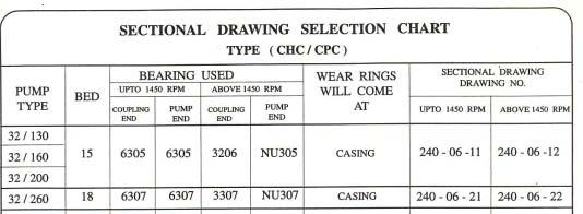
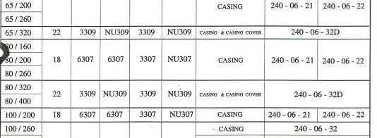
17 6.5 GENERAL The Booklet covers instructions for following models of Pumps. BEARING UNIT PUMP MODELS 15 32/130 50/160 65/160 40/130 32/200 80/160 32/160 40/200 65/200 40/160 50/200 80/ /200 50/260 40/320 32/260 65/260 50/320 40/260 80/ /260 80/320 80/ / / /400 65/ / / / / / / SAM Pumps are of Back Pull-out design which e'1ables to remove the rotating unit of pump for inspection and repairs without disturbing the pipe connection. While using a spacer type coupling motor also need not be disturbed Pumps when properly installed and given proper care in operation and Maintenance should operate satisfactorily for a long period When the pump is received, some time before the actual use of pump, it should be inspected and located in dry place. The coupling should be rotated once in a month to prevent pitting of bearing surfaces. 7. DISMANTLING AND ASSEMBLING: 7.1 GENERAL: If the pump has been maintained and serviced carefully, breakdowns which necessitate the pump being dismantled should not occur. If, however, faults occur, the cause should be located before dismantling if possible. If technical personnel are not available, we recommended that you request the service of an erection Engineer or dispatch the pump to our works for checking. If the pump is being stripped by yourselves, all parts must be handled with greatest care, avoiding blows and shocks. All parts must be carefully cleaned, tested for wear and if necessary, reconditioned or replaced with new parts. If new joints have to be made, if must be ensured that the correct measurements are observed (see sub-section 8.1) After assembly, the rotor must turn easily by hand. Otherwise the bearings, coupling, shaft and wear rings may get damaged prematurely.
18 7.2 DISMANTLING: The pumps offered are of back pull out type design. Hence while dismantling pump, casing will remain in its place with the suction and delivery piping. The rotating assembly can be pulled back easily. If spacer couplings are used, then the driver also need not be removed, thus enabling easy reassembling of the pump without affecting the alignment. We recommend to match-mark the parts before removing the spacer so as to ensure the original state of mounting when re-assembling. The coupling halves should only be mounted and dismounted by means of suitable extraction devices Drain the volute casing of the liquid handled and bearing housing (36.7) of oil Remove spacer coupling or if there is no such coupling, loosen driver and move it aside Loosen sealing liquid and coolant pipes and undo the fastening bolts on the support foot (91.13) Undo stud nuts on volute casing Using the two forcing screws on the casing cover withdraw the casing cover (17.3) bearing Lantern (35.6) and bearing housing (36.7) along with the complete rotor (figure2) After undoing the impeller nut (93.4) withdraw impeller with gasket (41.04) Removal of mechanical seal The rotating elements of the mechanical seal can be extracted together with the shaft sleeve (53.6) from the impeller side After undoing the forcing screws, separate casing cover (17.3) from bearing lantern (35.6) Removal of Packed Stuffing Box: After undoing the forcing screws, separate casing cover (17.3) together with packing, lantern ring (46.10) and gland (46.4) from bearing lantern (35.6) Remove shaft sleeve (53.6) gland (46.4) and deflector (51.9) (The shaft sleeve can be removed by means of an extractor disc, which we supply upon request, using a normal extraction device) Remove bearing cover, drive side (37.2) Drive out carefully pump shaft (22.3) with bearing towards drive side. In the case of the rolling contact bearing design with grooved ball bearings on the pump side see to it that the ball bearing, pump side (33.3) is properly introduced in to the bearing bore, drive side. If the pump is fitted with an angular contact ball bearing on the pump side, the outer ring of the cylindrical roller bearing including cage and rollers will remain in the bearing lantern (35.6) should these parts too have to be taken out then the bearing lantern (35.6) must be separated from the bearing housing (36.7) take into account the remarks made in sub section Heat the bearing and extract it see that the heat is not transmitted to the shaft If the bearing lantern (35.6) or the radial shaft seal (43.13) need not be changed, the bolts connecting the bearing lantern (35.6) to the bearing housing (36.7) should not be loosened, as this joint is sealed with a liquid sealant, otherwise these seal faces must be thoroughly cleaned and provided with liquid seal before re-assembly. Clean all dismantled parts and check them for wear.
19 7.3 ASSEMBLING: For assembly proceed in reverse sequence. After mounting the shaft check the axial float of the rotor mm with grooved ball bearing on the coupling and the pump side mm with an angular contact ball bearing on the coupling side and a cylindrical roller bearing on the pump side. Should new bearings be mounted on the shaft, they must first be heated upto about 80 0 C in an oil bath. The bearings must bear against the shaft shoulders. When installing the outer ring of the cylindrical roller bearing, this ring must bear against the shoulder of the bearing lantern (35.6). The bearings installed in our works have normal clearances. However, the use of bearings with. C3-play is permissible. NOTE: After mounting the casing cover (17.3) on to the bearing lantern (35.6), tighten it against the bearing lantern by means of the two forcing screw and a locking nut (figure 6). Pay attention to the o-rings and gaskets (see section drawings and section3). If they are to be changed see that the joint thickness is maintained.
20 8. SPARE PARTS SPARE PARTS FOR CHEMICAL PUMPS 8-1 (available from local market)


21

22


23

24


25


26

27


28


29


30


31


32


33


34


35


36


37
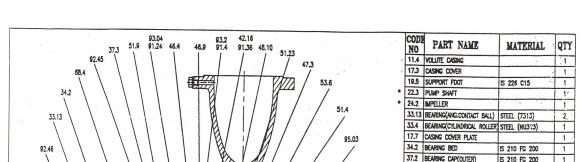
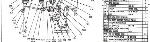
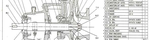
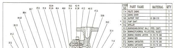
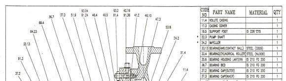
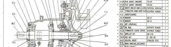
38 10.5 PARTS LIST. Part No. Name Part No. Name 11.4 Volute Casing 17.7 Casing cover plate 17.3 Casing Cover *51.23 Wear ring 19.5 Support Foot *51.9 Deflector *22.3 Pump Shaft 53.5 Shaft sleeve (Mech seal) *24.2 Impeller *53.6 Shaft sleeve (Packing) *33.3,33.13 Angular contact ball bearing 65.4,64.10 Oil level indicator *33.4 Cylindrical roller bearing 68.4 Vent 34.2,35.6 Bearing housing lantern Hex. head screw (forcing screw) 36.7 Bearing housing Hex. screw (support foot) 37.2 Bearing Cover Hex. screw 37.3 Inner bearing Cap Stud *41.03 Flat gasket (Washer) Stud (gland) *41.04 Flat gasket (Washer) Stud (Mech seal gland) Gasket Screw plug Gasket Sealing liquid connection Gasket Shaft sealing, cooling connection(inlet) 41.2 Gasket Oil drain Washer 91.3 Hex screw (brg cap) Washer 91.4 Stud Washer 91.5 Drain plug Washer Hex. Nut O' ring Hex. Nut Washer Hex. nut 42.4 O' ring Hex. nut *43.13 Oil Seal 93.2 Hex. nut *43.3 Oil seal/labyrinth Ring 93.3 Grooved nut *43.33 Labyrinth Ring *93.4 Impeller nut *43.5 Labyrinth Ring Lock washer *46.4 Gland (for packing) Hex. nut *46.9 Pressure ring *94.21 Helicoil insert *46.10 Lantern ring Circlip *47.3 Gland packing Circlip 48.3 Gland Plate (Mech seal) *95.03,95.05 Key (impeller) *51.4 Wear ring *95.2 Key (Coupling) * Recommended Spare parts for two years Normal Operation


39
40 11. TROUBLE CAUSE - REMEDY In the event of troubles we recommended to locate the cause using the following chart. Trouble Cause-Remedy No. 1. Pump does not deliver Pump delivers at reduced capacity Delivery Performance reduced Pump delivers too much Delivery is interrupted Pump runs in reverse direction Very noisy Unsteady running of pump Pump casing not leak proof Excessive leakage from stuffing box Fumes form stuffing box Mechanical seal leaking Pump rotor blocked in stand still position Pump is heating up and seizing Bearing temperature increase Motor will not start Motor is difficult to start Motor is running hot or burning out
41 CAUSE REMEDY 1. Suction filter, foot valve clogged 2. Nominal diameter of suction line too small 3. Suction does not reach down for enough into the delivery liquid 4. Ground clearance of suction too narrow 5. Too many bends in the suction line 6. Shut-off valve in the feed line in unfavourable position 7. Incorrect layout of suction line (formation of air pockets) 8. Valve (s) in the suction and/or feed line not fully open 9. Screwed joints or flanges in the suction line not leak-proof 10. Ingress of air via leaking valves and fittings in the suction line (Stuffing Box. etc) 11. Suction lift too great 12. Available NPSH too low (difference between pressure at suction branch and vapour pressure too low) 13. Cut-out level for starter too low (in automatic plants) 14. Delivery liquid containing too much gas and /or air 15. Delivery liquid too viscous 16. Insufficient venting 17. Speed too high (number of revolutions of driver higher than nominal number of revolutions of pump) 18. Speed too low (number of revolutions of driver lower than nominal number of revolutions of Pump) 19. Incorrect direction of rotation (electric motor, incorrectly connected, leads on the terminal board interchanged) 20. Impeller clogged 21. Impeller damaged 22. Wear rings worn 23. Separation of crystals from the delivery liquid (falling below the temperature limit/equilibrium temperature) 24. Sealing liquid line/circulation line clogged 25. Sealing liquid line contaminated 26. Lantern ring in the stuffing box is not positioned below the sealing liquid inlet 27. Sealing liquid omitted 28. Packing incorrectly fitted 29. Gland tightened too much/slanted 30. Packing incorrectly fitted 31. Mechanical seal blocked; O-ring-rotating seal ring or stationary seal ring damaged 32. Shaft sleeve/shaft worn in the region of the packing 33. Bearing worn out 34. Insufficient lubrication of bearings (also in case of automatic lubrication) 35. Specified oil level not maintained 36. Oil quality unsuitable 37. Rolling contact bearings in correctly fitted 38. Axial stress on rolling contact bearings (no axial clearance for rotor) 39. Bearing dirty 40. Bearing rusty (corroded) 41. Axial thrust too great because of worn wear rings, obstructed relief holes 42. Radial shaft seal ring has not much tension (local heating-up of shaft) 43. Insufficient cooling water supply

42 44. Sediment in the cooling water chambers 45. Alignment of coupling faulty or coupling loose 46. Elastic element of coupling worn 47. Foundation incorrectly performed 48. Base plate not rigid enough in the event of erection without foundation 49. Pump casing under stress 50. Pipe line under stress 51. Shaft runs untrue 52. Shaft bent 53. Rotor insufficiently balanced 54. Rotor parts touching the casing 55. Unsuitable casing seal. 56. Casing screw not tight enough 57. Vibration of pipe work 58. Non return valve gets stuck 59. Contaminated delivery liquid 60. Delivery flow too small 61. Delivery flow too great 62. Pump unsuitable for parallel operation 63. Type of pump unsuitable 64. Incorrect designing of pump for existing operating conditions 65. Voltage too low/power supply overloaded 66. Short circuit in the motor 67. Setting of circuit-breaker for motor handled too high 68. Temperature of the liquid too high 69. Spring of the mechanical seal damaged
SAM TURBO INDUSTRY LIMITED
 INSTRUCTIONS ON INSTALLATION, OPERATION AND MAINTENANACE FOR SAM TURBO PUMP TYPE TCC SAM TURBO INDUSTRY LIMITED NEELAMBUR, COIMBATORE-641 014. INDIA PH: 0422-3058899(50 LINES), FAX: 3058000, E-MAIL: info@sampumps.com,
SAM TURBO INDUSTRY PVT LIMITED
 INSTRUCTIONS ON INSTALLATION, OPERATION AND MAINTENANACE FOR SAM TURBO PUMP TYPE TCH+N SAM TURBO INDUSTRY PVT LIMITED NEELAMBUR, COIMBATORE-641014, INDIA 1 EXTRA HEAVY DUTY CHEMICAL PROCESS PUMPS AMERICAN
INSTALLATION, OPERATION AND MAINTENANCE INSTRUCTIONS
 INSTALLATION, OPERATION AND MAINTENANCE INSTRUCTIONS Contents Section 1. General Observations... 2 2. Operation... 4 3. Control During Operation... 5 4. Trouble Shooting... 6 5. Maintenance... 7 Please
SAM TURBO INDUSTRY LIMITED
 INSTRUCTIONS ON INSTALLATION, OPERATION AND MAINTENANACE FOR SAM TURBO PUMP TYPE ZM SAM TURBO INDUSTRY LIMITED NEELAMBUR, COIMBATORE-641 014. INDIA PH: 0422-3058899(50 LINES), FAX: 3058000, E-MAIL: mktg@sampumps.com,
SAM TURBO INDUSTRY LIMITED
 INSTRUCTIONS ON INSTALLATION, OPERATION AND MAINTENANACE FOR SAM TURBO PUMP TYPE MF SAM TURBO INDUSTRY LIMITED NEELAMBUR, COIMBATORE-641 014. INDIA PH: 0422-3058899(50 LINES), FAX: 3058000, E-MAIL: info@sampumps.com,
SERIES PC INSTRUCTION AND OPERATION MANUAL
 MEGGA SERIES PC INSTRUCTION AND OPERATION MANUAL Models PCT and PCF Close-coupled and frame-mounted single-stage horizontal end-suction pumps. WARNING: Read this manual before installing or operating this
PROCESS PUMPS (INDIA) PVT LTD
 PVT LTD") MANUAL: - M10 HORIZONTAL BPO METALLIC PUMP WITH EXTERNAL MECHANICAL SEAL (GROUP- III & IV) INSTALLATION, OPERATION AND MAINTENANCE MANUAL PROCESS PUMPS (INDIA) PVT LTD Plot No.86, III Phase, Peenya Industrial
MANUAL: - M10 HORIZONTAL BPO METALLIC PUMP WITH EXTERNAL MECHANICAL SEAL (GROUP- III & IV) INSTALLATION, OPERATION AND MAINTENANCE MANUAL PROCESS PUMPS (INDIA) PVT LTD Plot No.86, III Phase, Peenya Industrial
INSTRUCTIONS ON INSTALLATION OPERATION AND MAINTENANCE FOR KIRLOSKAR PUMP TYPE DB
 INSTRUCTIONS ON INSTALLATION OPERATION AND MAINTENANCE FOR KIRLOSKAR PUMP TYPE DB KIRLOSKAR BROTHERS LIMITED UDYOG BHAVAN, TILAK ROAD, PUNE - 4 002 KIRLOSKAR BROTHERS LIMITED Udyog Bhavan, Tilak Road,
PROCESS PUMPS (INDIA) PVT LTD
 PVT LTD") MANUAL: - M12 HORIZONTAL BPO METALLIC PUMP WITH GLAND PACKING (GROUP- III & IV) INSTALLATION, OPERATION AND MAINTENANCE MANUAL PROCESS PUMPS (INDIA) PVT LTD Plot No.86, III Phase, Peenya Industrial Area,
MANUAL: - M12 HORIZONTAL BPO METALLIC PUMP WITH GLAND PACKING (GROUP- III & IV) INSTALLATION, OPERATION AND MAINTENANCE MANUAL PROCESS PUMPS (INDIA) PVT LTD Plot No.86, III Phase, Peenya Industrial Area,
HORIZONTAL SPLIT CASING PUMP
 OPERATION & MAINTENANCE MANUAL HORIZONTAL SPLIT CASING A Mark of Quality CROSS SECTION DRAWING No. DESCRIPTION MATERIAL 01 1/4 BSP PLUG BRASS 02 LOWER HOUSING C. I. IS-210, FG260 03 IMPELLER C. I. / G.
PACKING, HANDLING, TRANSPORTING AND STORING MOTORS
 PACKING, HANDLING, TRANSPORTING AND STORING MOTORS Make sure that the shaft of the motor is not loaded in any way and is protected from knocks. Axial loads or shocks may easily damage the bearings inside
Installation Vertical Pump: Installation 'CM' and 'CDM' Style: Operation:
 Installation Vertical Pump: Gusher vertical end suction pumps with integral shaft is easily installed and put into service. With the one piece shaft design there is no couplings to align, no shims or no
INSTRUCTIONS ON INSTALLATION, OPERATION AND MAINTENANACE FOR SAM TURBO PUMP TYPE VO
 INSTRUCTIONS ON INSTALLATION, OPERATION AND MAINTENANACE FOR SAM TURBO PUMP TYPE VO SAM TURBO INDUSTRY LIMITED NEELAMBUR, COIMBATORE-641 014. INDIA PH: 0422-3058899(50 LINES), FAX: 3058000, E-MAIL: mktg@sampumps.com,
Medium and high pressure pumps
 Screw pumps Medium and high pressure pumps Installation and Start-up Instruction This instruction is valid for all standard high pressure pumps: E4, D4 and D6 Contents Page Pump identification 2 Installation
PROCESS PUMPS (INDIA) PVT LTD
 PVT LTD") VERTICAL CANTILEVER SHAFT SUMP PUMP (PPCS)_ METALLIC INSTALLATION, OPERATION AND MAINTENANCE MANUAL PROCESS PUMPS (INDIA) PVT LTD Plot No.86, III Phase, Peenya Industrial Area, Bangalore 560058 Phone:
VERTICAL CANTILEVER SHAFT SUMP PUMP (PPCS)_ METALLIC INSTALLATION, OPERATION AND MAINTENANCE MANUAL PROCESS PUMPS (INDIA) PVT LTD Plot No.86, III Phase, Peenya Industrial Area, Bangalore 560058 Phone:
PROCESS PUMPS (INDIA) PVT LTD
 PVT LTD") HYDRODYNAMIC SEAL NON METALLIC PUMP INSTALLATION, OPERATION AND MAINTENANCE MANUAL PROCESS PUMPS (INDIA) PVT LTD Plot No.86, III Phase, Peenya Industrial Area, Bangalore 560058 Phone: 91-80-28395327/28
HYDRODYNAMIC SEAL NON METALLIC PUMP INSTALLATION, OPERATION AND MAINTENANCE MANUAL PROCESS PUMPS (INDIA) PVT LTD Plot No.86, III Phase, Peenya Industrial Area, Bangalore 560058 Phone: 91-80-28395327/28
PROMAG SR SERIES SEAL-LESS CENTRIFUGAL PUMPS
 PROMAG SR SERIES SEAL-LESS CENTRIFUGAL PUMPS INSTALLATION, OPERATION, AND MAINTENANCE INSTRUCTIONS TO OBTAIN THE BEST PERFORMANCE FROM YOUR PROMAG SR PUMP, PLEASE READ THE MANUAL CAREFULLY. Failure to
End Suction Centrifugal
 M o d e l s 3 U / 3 U B End Suction Centrifugal Operating Instructions, Installation & Maintenance Manual Certified to NSF/ANSI 6, ANNEX G * NSF/ANSI 6 Annex G listed models: 3U EBARA International Corporation
1750 RPM Centrifugal Pumps
 Please read and save this Repair Parts Manual. Read this manual and the General Operating Instructions carefully before attempting to assemble, install, operate or maintain the product described. Protect
PROCESS PUMPS (INDIA) PVT LTD
 PVT LTD") MANUAL: - NM3 HORIZONTAL BPO NON METALLIC PUMP WITH DOUBLE MECHANICAL SEAL GROUP 0 INSTALLATION, OPERATION AND MAINTENANCE MANUAL PROCESS PUMPS (INDIA) PVT LTD Plot No.86, III Phase, Peenya Industrial
MANUAL: - NM3 HORIZONTAL BPO NON METALLIC PUMP WITH DOUBLE MECHANICAL SEAL GROUP 0 INSTALLATION, OPERATION AND MAINTENANCE MANUAL PROCESS PUMPS (INDIA) PVT LTD Plot No.86, III Phase, Peenya Industrial
Series Base mounted pump. Installation and operating instructions
 Series 4030 Installation and File No: 40.80 Date: june 25, 2015 Supersedes: 40.80 Date: october 10, 2009 contents General 4 Inspection 4 Installation - Series 4030 base mounted Pump 4 1.0 Location 4 2.0
NECO Pumping Systems
 INSTALLATION OPERATION & MAINTENANCE INSTRUCTIONS For Your NECO Pumping Systems Fuel Oil Transfer System THIS COMPLETELY ASSEMBLED, TESTED, PACKAGED SYSTEM IS OF THE HIGHEST QUALITY AND DESIGN. TO OBTAIN
INSTRUCTION MANUAL INTERNAL GEAR PUMP TITAN G-4124A SERIES=> FLANGED TITAN G-124A SERIES => FLANGED MODELS:
 INSTRUCTION MANUAL INTERNAL GEAR PUMP TITAN G-4124A SERIES=> FLANGED TITAN G-124A SERIES => FLANGED MODELS: G-H, G-HL, G-K, G-KK, G-L, G-LQ, G-LL, GLS, G-Q, G-QS 1 Contents Maintenance Thrust bearing adjustment
SAI GM Series Piston Hydraulic Motor Crankshaft Design Radial Piston Motors
 SAI GM Series Piston Hydraulic Motor Crankshaft Design Radial Piston Motors www.chinawinches.cn (Dimension: inch) Brief Performance Table of Sai GM Series Piston Hydraulic Motor (Full range GM05- GM9 series)
SLR / SLR-S/N. Instruction Manual. Walrus America Inc
 SLR / SLR-S/N Instruction Manual Walrus America Inc 1. Installation and Connection 1.1. Pump Installation The pump should be sited in a well ventilated and frost-free position. The distance between pumps-motors
INSTRUCTIONS Installation Operation Repair
 Peerless Pump Company 2005 Dr. M.L. King Jr. Street, P.O. Box 7026, Indianapolis, IN 46207-7026, USA Telephone: (317) 925-9661 Fax: (317) 924-7338 www.peerlesspump.com www.epumpdoctor.com INSTRUCTIONS
1750 RPM Centrifugal Pumps
 Please read and save this Repair Parts Manual. Read this manual and the General Operating Instructions carefully before attempting to assemble, install, operate or maintain the product described. Protect
The ELM Series Slurry Pump Installation and Operating Manual
 The ELM Series Slurry Pump Installation and Operating Manual Excellence Pump Industry Co., Ltd. SAFETY INFORMATION The following safety information relating to pump operation and maintenance should be
DISASSEMBLY AND ASSEMBLY INSTRUCTIONS FOR LIQUID RING VACUUM PUMPS
 (Rev. 2.0_10-2010) DISASSEMBLY AND ASSEMBLY INSTRUCTIONS FOR LIQUID RING VACUUM PUMPS TRVK 2003 to 5003 TRSK 2005 to 5005 INTRODUCTION These instructions are for the maintenance staff in case of repair
INSTRUCTIONS ON INSTALLATION OPERATION AND MAINTENANCE FOR KIRLOSKAR PUMP TYPE DSM (STANDARD)
") INSTRUCTIONS ON INSTALLATION OPERATION AND MAINTENANCE FOR KIRLOSKAR PUMP TYPE DSM (STANDARD) KIRLOSKAR BROTHERS LIMITED UDYOG BHAVAN, TILAK ROAD, PUNE - 4 00 KIRLOSKAR BROTHERS LIMITED Udyog Bhavan, Tilak
INSTRUCTIONS ON INSTALLATION OPERATION AND MAINTENANCE FOR KIRLOSKAR PUMP TYPE DSM (STANDARD) KIRLOSKAR BROTHERS LIMITED UDYOG BHAVAN, TILAK ROAD, PUNE - 4 00 KIRLOSKAR BROTHERS LIMITED Udyog Bhavan, Tilak
PUMPS STEAM TURBINES BUILDING & FIRE WASTEWATER SERVICE PUMP CLINIC 15 MECHANICAL SEAL DESIGN, OPERATION AND MAINTENANCE PROBLEMS
 PUMP CLINIC 15 MECHANICAL SEAL DESIGN, OPERATION AND MAINTENANCE PROBLEMS In my seminars I teach that mechanical seals fail prematurely because: The lapped faces open A seal component becomes damaged In
SERIES G3DB/AG3DB ELEVATOR
 TM INSTRUCTIONS AND PARTS LIST SERIES G3DB/AG3DB ELEVATOR WARNING This manual, and GENERAL INSTRUCTIONS MANUAL, CA-1, should be read thoroughly prior to pump installation, operation or maintenance. SRM00059
Operating & Maintenance Manual For Steam Conditioning Valve
 For Steam Conditioning Valve 1 Table of Contents 1.0 Introduction 3 2.0 Product description 3 3.0 Safety Instruction 4 4.0 Installation and Commissioning 5 5.0 Valve Disassembly 6 6.0 Maintenance 6 7.0
ABS Dry Installed Waste Water Pumps Series FR
 A Operating Instruction 3 ABS Dry Installed Waste Water Pumps Series FR Shaft Seal Close-coupled and Bearing Assemblies 3R, 4R, 5R, 5F and 6F! Observe for hazardous liquids that there can be liquid left
Installation and Start-up Instruction. This instruction is valid for all standard low pressure pumps: LPD, ACD, ACE, ACG/UCG, ACF/UCF, LPQ and ABQ
 Screw pumps Low pressure pumps Installation and Start-up Instruction This instruction is valid for all standard low pressure pumps: LD, ACD, ACE, ACG/UCG, ACF/UCF, LQ and AQ Contents age ump identification
MAINTENANCE AND REPAIR INSTRUCTIONS
 MAINTENANCE AND REPAIR INSTRUCTIONS TYPE TH PUMPS Peerless Pump Company Indianapolis IN, 46207-7026 4849357 TABLE OF CONTENTS Maintenance Page 1 & 2 Disassembly Page 5 & 6 Impeller Clearance 3 Reassembly
300 SERIES 331, 332, 333, 344, 356 AND 367 MODELS
 Section: MOYNO 500 PUMPS Page: 1 of 8 Date: March 1, 1998 SERVICE MANUAL MOYNO 500 PUMPS 300 SERIES 331, 332, 333, 344, 356 AND 367 MODELS Mechanical Seal Models Packing Gland Models MODELS DESIGN FEATURES
Series Base mounted pump. Installation and operating instructions
 Series 4030 Installation and File No: 40.80 Date: december 12, 2016 Supersedes: 40.80 Date: july 27, 2016 contents General 4 Inspection 4 Installation - Series 4030 base mounted Pump 4 1.0 Location 4
SERVICE MANUAL 200 SERIES MOTORIZED 20352, 20452, 20551, 20552, AND MODELS
 Section: MOYNO 500 PUMPS Page:1 of 4 Date: March 1, 1998 SERVICE MANUAL MOYNO 500 PUMPS 200 SERIES MOTORIZED 20352, 20452, 20551, 20552, 22051 AND 22052 MODELS DESIGN FEATURES Housing: AISI 316 stainless
SAM TURBO INDUSTRY LIMITED
 INSTRUCTIONS ON INSTALLATION, OPERATION AND MAINTENANACE FOR SAM TURBO PUMP TYPE AR SAM TURBO INDUSTRY LIMITED NEELAMBUR, COIMBATORE-641 014. INDIA PH: 0422-3058899(50 LINES), FAX: 3058000, E-MAIL: info@sampumps.com,
Starting up hydraulic systems
 General / Installation A hydraulic system that operates economically, safely, and trouble-free requires careful planning, as well as proper installation and start-up. Conscientious maintenance has a considerable
FOR ROTARY TYPE TWIN GEAR. Pump Type: HGSX
 FOR ROTARY TYPE TWIN GEAR Pump Type: HGSX MODEL : CLIENT : PROJECT : P.O. NO. : SR. NO. : W.O. No. : MANUFACTURER : DEL Pd PUMPS & GEARS PVT LTD. HEAD OFFICE & WORKS : PLOT NO: 113, GIDC ESTATE, WADHWANCITY
ISO 9001 CERTIFIED COMPANY INDUSTRIAL PUMPS. Installation & Operational Manual For BACK-PULL-OUT PUMP
 ISO 9001 CETIFIE COPANY Installation & Operational anual For BACK--OT P EX Assembly isassembly Erection Starting unning Stopping and aintenance Cautions in use of echanical Seal Stuffing Box and Packing
 AUTOGARD SERIES 820 TORQUE LIMITER Installation and Maintenance Manual DB0009 Issue 11 21 Feb 2017 British Autogard Ltd 2 Wilkinson Rd., Love Lane Industrial Estate, Cirencester, Glos., GL7 1YT UK Tel.
INSTRUCTION MANUAL AC2516 REVISION D INSTALLER: PLEASE LEAVE THIS MANUAL FOR THE OWNER S USE. Series 1580 In-Line Mounted Centrifugal Fire Pumps
 INSTRUCTION MANUAL AC2516 REVISION D INSTALLER: PLEASE LEAVE THIS MANUAL FOR THE OWNER S USE. Series 1580 In-Line Mounted Centrifugal Fire Pumps PUMP LOCATION Locate the pump so there is sufficient room
Norm-Centrifugal Pumps PN 10
 Norm-Centrifugal Pumps PN 10 Pump dimensions acc. to DIN EN 733 with additional sizes Technical requirements acc. to DIN ISO 9908 Application For pumping pure water, industrial water, sea water, condensate,
INSTALLATION, OPERATION AND MAINTENANCE INSTRUCTIONS. Mr. Proprietor
 INSTALLATION, OPERATION AND MAINTENANCE INSTRUCTIONS APN PUMPS Mr. Proprietor Congratulations! You have just purchased an equipment of simple construction, designed with the most advanced technology, with
TILLOTSON LTD., CLASH INDUSTRIAL ESTATE, TRALEE, CO. KERRY, IRELAND PHONE: FAX:
 TILLOTSON LTD., CLASH INDUSTRIAL ESTATE, TRALEE, CO. KERRY, IRELAND PHONE: +353 66 7121911 FAX: +353 66 7124503 e-mail: sales@tillotson.ie SERIES SERVICE MANUAL INTRODUCTION The gasoline engine industry
TECHNICAL SERVICE MANUAL
 Electronic copies of the most current TSM issue can be found on the Viking Pump website at www.vikingpump.com TECHNICAL SERVICE MANUAL VIKING HELICAL GEAR REDUCERS A, B, AND C SIZES SECTION PAGE ISSUE
Installation Procedures
 For the precision ball and roller bearings supplied by MRC Bearings, skill and cleanliness while handling, mounting and dismounting are necessary to ensure satisfactory bearing performance. As precision
SUMMIT PUMP Horizontal End Suction Pump Close Coupled and Frame Mounted
 SUMMIT PUMP Horizontal End Suction Pump Close Coupled and Frame Mounted Installation, Operation, and Maintenance Manual 2014 by Summit Pump, Inc. All rights reserved. WARRANTY Pumping units assembled
SUMMIT PUMP. Model DSR Single Stage, Double Suction Pumps Installation, Operation, and Maintenance Manual
 SUMMIT PUMP Model DSR Single Stage, Double Suction Pumps Installation, Operation, and Maintenance Manual 2014 by Summit Pump, Inc. All rights reserved. WARRANTY Pumping units assembled by Summit Pump,
series 1500 horizontal pumps
 Fybroc Division series 1500 horizontal pumps INSTALLATION MANUAL INDEX Page Page Fybroc Warranty 3 Assembly/Disassembly Procedures 10 Installation Instructions 4 General 10 Location 4 Disassembly 10 Foundation
Before you go through this booklet, we request you to go through the following general instruction before commissioning your hydraulic systems.
 Hello, We are proud to be on your suppliers list. During few years we came to know that most of our customers are satisfied by Yuken Hydraulic Products but some of our customers had minor problems and
END SUCTION CENTRIFUGAL PUMPS
 OWNERS GUIDE TO INSTALLATION AND OPERATION FW000 009 Supersedes 07 END SUCTION CENTRIFUGAL PUMPS READ THESE INSTRUCTIONS CAREFULLY Read these installation instructions in detail before installing your
INSTRUCTION, INSTALLATION, MAINTENANCE AND REPAIR MANUAL MODEL 3310
 SECTION 6 ITEM 3310 DATED JUNE 1, 2007 INSTRUCTION, INSTALLATION, MAINTENANCE AND REPAIR MANUAL 6 MODEL 3310 IMPORTANT NOTE TO INSTALLER: This manual contains important information about the installation,
Maintenance Instructions
 General Note These instructions contain information common to more than one model of Bevel Gear Drive. To simplify reading, similar models have been grouped as follows: GROUP 1 Models 11, 0, 1,, (illustrated),,
TECHNICAL SERVICE MANUAL GENERAL PURPOSE JACKETED PUMPS SERIES 230 MODELS HX4, KK, LQ, Q, M, N
 CONTENTS TECHNICAL SERVICE MANUAL GENERAL PURPOSE JACKETED PUMPS SERIES 230 MODELS HX4, KK, LQ, Q, M, N SECTION 2 BULLETIN TSM-230-V ISSUE A Special Information 2 Maintenance 2 Packed Pump Breakdown Drawing
NOTE: Visit our website at for video repair procedures, under the Tools section.
 Repair Instructions Hypro Repair Tools: Tool Box No. 3010-0168 1/4" Allen Wrench No. 3020-0008 Support Bars (2) No. 3010-0064 Port Brush No. 3010-0066 1/16" Allen Wrench No. 3020-0009 Brush Holder No.
BOILER FEED SYSTEM OPERATION AND MAINTENANCE MANUAL
 BOILER FEED SYSTEM OPERATION AND MAINTENANCE MANUAL IMPORTANT These instructions are intended as a guide for the Installing Contractor and as a reference for the Operator, Owner and Serviceman. RETAIN
S3 General Installation
 Wilfley Drylock Assembly General Installation Operating & General Servicing Clearance Settings Safety Precautions Spare Parts Ordering Assembly Instructions Model S3 General Installation Inspection upon
PUMP PRIMING INSTALLATION CHECK MOTOR ROTATION PUMP START-UP MOTOR REPLACEMENT DISASSEMBLY ELECTRICAL HOOKUP ASSEMBLY
 V6 VERTICAL BOOSTER PUMP OWNER'S MANUAL BEFORE INSTALLING PUMP, BE SURE TO READ THIS OWNER S MANUAL CAREFULLY. C A U T I O N Mechanical shaft seals must not run dry. Fill pump with water before starting
INSTRUCTIONS ON INSTALLATION OPERATION AND MAINTENANCE FOR KIRLOSKAR PUMP TYPE SHM
 INSTRUCTIONS ON INSTALLATION OPERATION AND MAINTENANCE FOR KIRLOSKAR PUMP TYPE SHM KIRLOSKAR BROTHERS LIMITED UDYOG BHAVAN, TILAK ROAD, PUNE - 00 KIRLOSKAR BROTHERS LIMITED Udyog Bhavan, Tilak Road, Pune
Agri KAM INSTALLATION, OPERATION AND MAINTENANCE MANUAL. A View of KBL Dewas Manufacturing Plant. A Kirloskar Group Company KIRLOSKAR BROTHERS LIMITED
 A View of KBL Dewas Manufacturing Plant KIRLOSKAR Agri KAM MONOBLOC KIRLOSKAR BROTHERS LIMITED A Kirloskar Group Company CORPORATE OFFICE : YAMUNA, Survey No. 98 (-7), Baner, Pune 411 045 (India) Phone
CSO / CP PUMPS Vertical Spindle Type Installation, Operation and Maintenance Manual
 CSO / CP PUMPS Vertical Spindle Type Installation, Operation and Maintenance Manual www.sameng.co.za (011) 823 4250 Proud Manufacturers of SAMCO Pumps Contents INTRODUCTION 3 LOCATION OF UNIT 3 INSTALLATION
SELF PRIMING CHEMICAL SERVICE PUMPS
 SELF PRIMING CHEMICAL SERVICE PUMPS INSTALLATION AND OPERATING INSTRUCTIONS This Manual covers: SELF PRIMING MODEL RANGE J50ECX TO J250ECX STAINLESS STEEL*, and NON METALLIC SEAL PUMP MODEL: SERIAL NO:
our contribution for Sealless Magnetic Coupled Multistage Centrifugal Pumps Type HZM / HZMR / HZMB environmental protection
 Sealless Magnetic Coupled Multistage Centrifugal Pumps Type HZM / HZMR / HZMB our contribution for environmental protection General DICKOW-pumps of series HZM are sealless multistage horizontal centrifugal
Gear pump manual for foam pelton wheel driven pumps
 Albany Pumps AN EMPLOYEE OWNED COMPANY OPERATING AND MAINTENANCE Gear pump manual for foam pelton wheel driven pumps THIS MANUAL SHOULD BE USED ALONGSIDE THE ALBANY STANDARD INSTALLATION, OPERATION AND
3. BEARING ARRANGEMENT DESIGN
 3. BEARING ARRANGEMENT DESIGN 3.1 GENERAL PRINCIPLES OF ROLLING BEARING ARRANGEMENT DESIGN Rotating shaft or another component arranged in rolling bearings is guided by them in radial as well as in axial
TECHNICAL SERVICE MANUAL GENERAL PURPOSE BRACKET MOUNTED PUMPS SERIES 115 MODELS G, GX2, H and HX4
 TECHNICAL SERVICE MANUAL GENERAL PURPOSE BRACKET MOUNTED PUMPS SERIES 115 MODELS G, GX2, H and HX4 SECTION 2 BULLETIN TSM-115-C ISSUE A CONTENTS Special Information 2 Maintenance 2 Packed Pump Breakdown
NEOTECHA NTB-NTC BALL VALVES INSTALLATION AND MAINTENANCE INSTRUCTIONS
 Before installation these instructions must be fully read and understood 2 SAFETY Please also read through these notes carefully. 2.1 General potential danger due to: a. Failure to observe the instructions
KEEN INDUSTRIAL PUMP CO. Inc.
 KEEN INDUSTRIAL PUMP CO. Inc. 471 E State Route 250 East, Ashland, Ohio 44805 PH: 419-903-0160 FX: 419-207-8031 INSTALLATION AND SERVICE INSTRUCTIONS AND REPAIR PARTS LIST FOR 5-20HP TWO STAGE CENTRIFUGAL
Matala. VersiFlow Series. Instruction and Maintenance Manual
 VersiFlow Series High Flow Multi-Purpose "Versatile " Pump V-3200 1/5HP 150W / Discharge 2 V-3900 1/3HP 250W / Discharge 2 V-4700 1/2HP 400W / Discharge 2 V-5600 1HP 750W / Discharge 2 Instruction and
OPERATION MANUAL INTERNAL GEAR PUMP. Models: NG-H, NG-HL, NG-K, NG-KK, NG-L, NG-LQ, NG-LL, NG-LS, NG-Q, NG-QS. Tel: Fax:
 OPERATION MANUAL INTERNAL GEAR PUMP Models: NG-H, NG-HL, NG-K, NG-KK, NG-L, NG-LQ, NG-LL, NG-LS, NG-Q, NG-QS. 1 Contents Pump Designation System Maintenance Thrust bearing adjustment Pressure Relief Valve
OPERATION & MAINTENANCE MANUAL HANGZHOU FLYING TECHNOLOGY CO., LTD.
 CENTRIFUGAL PUMP ZPD6-25*7 OPERATION & MAINTENANCE MANUAL HANGZHOU FLYING TECHNOLOGY CO., LTD. CONTENTS 1. GENERAL (1) 2. NOMENCLATURE OF THE TYPE (1) 3. MAIN TECHNICAL SPECIFICATIONS RANGE (1) 4. STANDARD
 INSTRUCTIONS Your Ampco centrifugal pump is a rugged unit designed to provide years of low cost pumping service. There is a small amount of necessary care required to ensure you of this expected long service.
INSTALLATION, OPERATION AND MAINTENANCE MANUAL (IOM)
") INSTALLATION, OPERATION AND MAINTENANCE MANUAL (IOM) IOM-1088 03-16 Model 1088 Vacu-Gard Blanketing Valve ISO Registered Company SECTION I I. DESCRIPTION AND SCOPE The Model 1088 Vacu-Gard is a tank blanketing
INSTALLATION, OPERATION AND MAINTENANCE MANUAL (IOM) IOM-1088 03-16 Model 1088 Vacu-Gard Blanketing Valve ISO Registered Company SECTION I I. DESCRIPTION AND SCOPE The Model 1088 Vacu-Gard is a tank blanketing
XFLO XS SERIES. Single Stage Double Suction Split Casing Centrifugal Pump
 XFLO P U M P S XS SERIES Single Stage Double Suction Split Casing Centrifugal Pump General and Construction 1. Applications Waterworks, Irrigation, Drainage pumping stations, Power stations, Industrial
FUNCTION OF A BEARING
 Bearing FUNCTION OF A BEARING The main function of a rotating shaft is to transmit power from one end of the line to the other. It needs a good support to ensure stability and frictionless rotation. The
TECHNICAL SERVICE MANUAL HEAVY-DUTY BRACKET MOUNTED PUMPS SERIES 120 and SERIES 124 MODELS J, K, KK, L, LQ, LL AND LM
 TECHNICAL SERVICE MANUAL HEAVY-DUTY BRACKET MOUNTED PUMPS SERIES 120 and SERIES 124 MODELS J, K, KK, L, LQ, LL AND LM SECTION 3 BULLETIN TSM-120-124-V ISSUE B-2005 CONTENTS Special Information 2 Maintenance
OPERATION, MAINTENANCE AND OVERHAUL INSTRUCTIONS FOR PB18 SERIES PORTABLE PUMPS
 WATEROUS COMPANY Form No. F 2058 South St. Paul, Minnesota 55075 January, 1992 OPERATION, MAINTENANCE AND OVERHAUL INSTRUCTIONS FOR PB18 SERIES PORTABLE PUMPS Printed in U.S.A. Waterous Company F 2058
Impeller Replacement
 Impeller Replacement Threaded Shaft Frame Mount H 806 Clockwise Rotation Volute shown. 1149 0794 1 Unfasten hardware holding volute to bracket. Remove volute to expose impeller. Peel off old volute gasket
TWO-STAGE HYDRAULIC PUMP. RWP55-IBT-Air
 ORIGINAL INSTRUCTIONS Form No.1000458 5 SPX Corporation 5885 11th Street Rockford, IL 61109-3699 USA Tech. Services: (800) 477-8326 Fax: (800) 765-8326 Order Entry: (800) 541-1418 Fax: (800) 288-7031 Internet
This manual presents installation, servicing, troubleshooting, and maintenance for M PUMPS CM MAG-M SERIES Information that may be required regarding
 Installation, Operating, Maintenance & Safety Instruction for M PUMPS CM MAG-M SERIES Centrifugal light Mag-Drive pumps (CM MAG-M06/1/2/3/4) This manual presents installation, servicing, troubleshooting,
END SUCTION CENTRIFUGAL PUMPS
 OWNERS GUIDE TO INSTALLATION AND OPERATION END SUCTION CENTRIFUGAL PUMPS FW000 0 Supersedes 009 READ THESE INSTRUCTIONS CAREFULLY Read these installation instructions in detail before installing your pump.
TECHNICAL SERVICE MANUAL
 TECHNICAL SERVICE MANUAL VIKING HELICAL GEAR REDUCERS "A", "B", AND "C" SIZES SECTION TSM 610 PAGE 1 OF 9 ISSUE E CONTENTS Special Information 2 Lubrication 2 Installation 3 Operation 3 Disassembly 3 Assembly
MUELLER ECCENTRIC PLUG VALVE
 MUELLER INSTALLATION, OPERATING and MAINTENANCE INSTRUCTIONS 1 MUELLER System Design The life of the valve is dependent on its application, frequency of use and freedom from misuse. The properties of the
These installation and maintenance instructions must be read in full and completely understood before the installation!
 These installation and maintenance instructions must be read in full and completely understood before the installation! 1. General information on the installation and maintenance instructions These instructions
1. SPECIFICATION. Altitude of motor installation. Information: Resistance and temperature specifications of the PTC thermistor / posistor/.
 1. SPECIFICATION 5 GENERAL INFORMATION Motors with parameters according to the data sheet comply with the requirements of the IEC 60034-1 standard, and IEC 60034-30 class efficiency IE2 Motor versions:
4 - Way Control 4 - Way Control 4 - Way Control with lock
 INSTALLATION / OPERATION / MAINTENANCE 1. DESCRIPTION MODEL 0-02 (Full Internal Port) Powertrol Valve This manual contains information for installation, operation and maintenance of the Cla-Val Co. 0-02
Installation, Operation and Maintenance Manual SCP/SFP SELF PRIMING PUMPS
 Installation, Operation and Maintenance Manual SCP/SFP SELF PRIMING PUMPS IMPORTANT - WARRANTY CLAUSE ROTECH PUMPS: Pumps manufactured & assembled by Rotech, are covered by warranty for free of manufacturing
CONTENTS. VIKING PUMP, INC. A Unit of IDEX Corporation Cedar Falls, IA USA SECTION TSM 710.1
 TECHNICAL SERVICE MANUAL industrial heavy duty motor speed pumps SERIES 4076 AND 4176 SIZES hle, ate and ale SECTION TSM 710.1 PAGE 1 of 8 ISSUE B CONTENTS Introduction....................... 1 Safety
WMTA6 LN SERIES SEAL-LESS MAG-DRIVE MULTI-STAGE TURBINE PUMPS
 WMTA6 LN SERIES SEAL-LESS MAG-DRIVE MULTI-STAGE TURBINE PUMPS INSTALLATION, OPERATION, AND MAINTENANCE INSTRUCTIONS TO OBTAIN THE BEST PERFORMANCE FROM YOUR WARRENDER WMTA6 LN PUMP, PLEASE READ THIS MANUAL
TILLOTSON LTD., CLASH INDUSTRIAL ESTATE, TRALEE, CO. KERRY, IRELAND PHONE: FAX:
 TILLOTSON LTD., CLASH INDUSTRIAL ESTATE, TRALEE, CO. KERRY, IRELAND PHONE: +353 66 7121911 FAX: +353 66 7124503 e-mail: sales@tillotson.ie HR SERIES SERVICE MANUAL INTRODUCTION Tillotson has developed
Voltmaster Centrifugal Trash Pumps
 Voltmaster Centrifugal Trash Pumps Model TSP2, TSP3 and TSP4 Owner s Manual February 2011 Table of Contents 1 Introduction............................ 1 1.1 Read before using..................... 1 1.2
MSC Manifolds - DIN for Steam Distribution and Condensate Collection Installation and Maintenance Instructions
 1170650/3 IM-P117-17 ST Issue 3 MSC Manifolds - DIN for Steam Distribution and Condensate Collection Installation and Maintenance Instructions 1 General safety information 2 General product information
Split Body Valves with Bellows Seal Series Globe Valves Series Angle Valves Series Way-Valves
 Installation, Operation, Maintenance Instructions Split Body Valves with Bellows Seal Series 025 300 Globe Valves Series 027 300 Angle Valves Series 028 300 3-Way-Valves 1 GENERAL INFORMATION These instructions
Instructions for installation, operation and maintenance of: GATE VALVE
 Instructions for installation, operation and maintenance of: GATE VALVE GEN GAC GAF/GENF TERMOVENT SC Temerin Republic of Serbia Instruction for installation, operation and maintenance: Table of Contents
Operating Instructions
 Operating Instructions BE2700 Brinkmann Immersions pumps of the series TA/STA/TAL/SAL901... 1303 Contents 1 General...1 2 Safety...2 3 Transport and storage...2 4 Description of product and accessories...2
Operating Instruction
 Operating Instruction Drive element LEWA - ecosmart type LCA with manual stroke adjustment, motor mounted vertically Table of contents 1 General information / safety 1.1 Important preliminary information