series 1500 horizontal pumps
|
|
|
- Shauna Rice
- 6 years ago
- Views:
Transcription


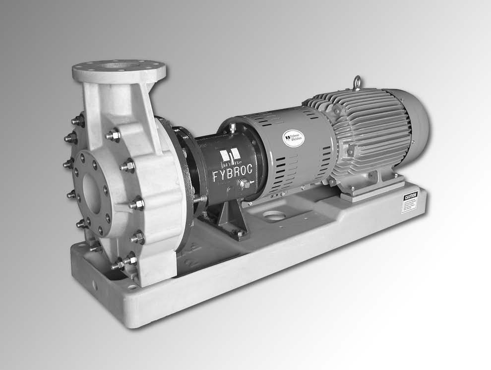

1 Fybroc Division series 1500 horizontal pumps INSTALLATION MANUAL
2 INDEX Page Page Fybroc Warranty 3 Assembly/Disassembly Procedures 10 Installation Instructions 4 General 10 Location 4 Disassembly 10 Foundation 4 Power-frame Disassembly 11 Initial Alignment 4 Power-frame Assembly 12 Piping the Pump 5 Pump End Assembly 13 Suction Piping 5 John Crane Type 8B2 13 Discharge Piping 5 John Crane Type 8-1T 14 Ancillary Piping 5 John Crane Type 8-D 14 Electrical Connections 6 Packed Stuffing Box 15 Rotation 6 Impeller Adjustment 16 Alignment and Coupling Installation 6 Installation Instructions Flex-Type Couplings 17 Start-up and Operating Procedures 7 Operational Start-up Checklist 19 Lubrication 7 Sectional Drawings 20 Oil Bath Lubrication Group I 20 Re-Greasable Bearings Group II 21 Greased for Life Bearings Group III 22 Seal Flushing 7 Typical Mechanical Seal Installations 23 Mechanical Seals 7 Product Flush 23 Packed Stuffing Box 7 External Flush 24 Priming 7 Mechanical Seal Piping/Flow Requirements 25 Starting 7 Single Mechanical Seal 25 Operational Check List 8 Double Mechanical Seal 26 Maintenance 8 Notes 27 Pump 8 Notes 28 Oil Bath Lubrication 8 Notes 29 Re-Greasable Bearings 8 Greased for Life Bearings 8 Motor 8 Trouble Check List 9 ORDERING REPLACEMENT PARTS For future reference fill in the following information from the pump nameplate. This will be necessary to ensure accuracy when ordering replacement parts. Model Size Serial Number Impeller Diameter Installed Seal Type Material of Construction
3 Fybroc Division WARRANTY PERFORMANCE GUARANTEE ACCEPTANCE TESTS PERFORMANCE REPRESENTATIONS FIELD TESTING ALL WARRANTIES RECOMMENDATIONS FOR SPECIAL MATERIALS FYBROC pumps are warranted by the Company, insofar as the same are of its own manufacture, against defects in materials and workmanship under proper and normal use and service, for a period of one year from the date of original shipment from the factory. FYBROC s obligation is limited, however, to furnishing without charge, F.O.B. its factory, new parts to replace any similar parts of its own manufacture so proving defective within said period, provided the Buyer has given FYBROC immediate written notice upon discovery of such defect. No allowance will be made for labor charges. FYBROC shall have the option of requiring the return of the defective material, transportation prepaid, to establish the claim. FYBROC makes no warranty or guarantee whatsoever, either express or implied, of prime mover, starting equipment, electrical apparatus, parts or material not manufactured by Fybroc, except to the extent that warranty is made by the manufacturer of such equipment and material. FYBROC assumes no liability for damages or delays caused by defective material, and no allowance will be made for local repair bills or expenses without the prior written approval or authority of FYBROC. Under no circumstances will FYBROC be liable for indirect, special or consequential loss or damage of any kind and the Buyer assumes all liability for the consequences of its use or misuse by the by the Buyer, his employees, or others. Is at the specified point of rating only and will not cover performance under conditions varying therefrom, nor for sustained performance over any period of time. If required, shall be conducted in accordance with the practices as set forth in the Hydraulic Institute Standards. The expense of any such tests shall be borne by the buyer. Are based on shop laboratory tests with cold water as outlined in the Hydraulic Institute Standards. Due to the inaccuracies of field testing, the results of any such tests conducted by or for the Buyer shall be interpreted as being only indicative of the actual field performance of the pump. No equipment will be furnished on the basis of acceptance by results of field tests. If the buyer, after such a test, questions the performance of the pump, he may at his option request a test to establish the performance. Such tests will be conducted in accordance with the above paragraph entitled Acceptance Tests. Are void if - a. Pipe strains are the cause of damage. b. Pump handles liquids other than those specified in detail. c. NPSH lower than required by pump impeller. d. Operating speed is higher than specified. e. Improper field installation. To combat corrosion, abrasion, erosion, or pumping solids, foreign objects, or pumping liquids at elevated temperature, any such recommendations will be based on the best available experience of FYBROC and the supplier of the material and industry, BUT WILL NOT CONSTITUTE A GUARANTEE AGAINST THESE EFFECTS. The foregoing warranty is made in lieu of all other warranties guarantees, obligations or liabilities, expressed or implied, by FYBROC or its representatives. All statutory or implied warranties, other than of title, are hereby expressly negated and excluded. All illustrations and provisions in specifications are descriptive and are not intended as warranties. Penalty of any kind are not acceptable unless approved in writing by an officer of Met-Pro Corporation. 3
4 INSTALLATION HORIZONTAL PUMPS LOCATION The pump should ideally be placed as close as possible to the liquid supply source. Allow sufficient space on the sides and overhead to permit inspection and maintenance work to be performed. FOUNDATION The foundation for the pump should be level, provide rigid support and alignment of pump and motor. It should also be of sufficient mass to dampen any vibrations developed. Typically this is accomplished by installing and grouting a Fybroc baseplate on a concrete foundation. Foundation bolts of the proper size should be imbedded in the concrete with anti-rotation lugs, located by a drawing or template. (See Figure 1 and Table 1 below for bolt-size and locations). A pipe sleeve larger than the bolt should be used to allow enough lateral movement for final positioning of the bolts. (See Figure 2 below). Leveling wedges or shims should be placed under the sides of the baseplate to level the unit and the foundation bolts slightly tightened. A wood form can now be built around the edge of the baseplate to contain the grout. The top of the rough concrete foundation should be wetted down prior to grouting. A good grade of non-shrinking grout can now be poured through the fill hole on the top of the fiberglass baseplate. On baseplates with raised motor mounting sections, a short length of pipe or tubing can be fitted into the grout hole to allow the grout to completely fill the raised section to the baseplate up to the vent hole in the raised section, as shown in figure below. Once the grout starts to set, the extension can be removed, leaving the grout level with the top of the baseplate. Once the grout has fully hardened, usually about 48 hours after pouring, the foundation bolts can be fully tightened. FIGURE 2 FIGURE 1 TABLE 1 Base A B C D E F G Bolt Plate Size 1T / /8 3 3/8 3/4 1/2 2T / /8 2 7/8 3/4 1/ / /4 2 3/4 3/4 1/ / /4 3 3/4 3/4 1/ / / / / / /2 4 1/2 1 3/ / /2 4 1/2 1 3/4 INITIAL ALIGNMENT Alignment of the pump and driver through the flexible coupling is of extreme importance for trouble-free mechanical operation. If the driver was mounted at the factory, the unit was rough aligned prior to shipment. However, in transit and subsequent handling, this factory alignment was possibly disturbed, and it is recommended the alignment be checked. The following steps are suggested to establish the initial alignment of the pump unit: 1) Be sure the foundation bolts are tight. 2) Be sure the casing and frame feet are tight. 3) Use shims under the driver feet to establish parallel and angular alignment of pump and motor shafts. 4
5 PIPING THE PUMP Piping must not be connected to the pump until base, pump, and driver are initially aligned, failure to do so may result in the inability to attain proper alignment later. All flanged connections to the pump should be full flat face with full contact gaskets. Raised face flanges or partial contact gaskets should not be used as excessive strains can be applied to the pump flanges upon tightening. The pump has been designed with all necessary strength factors for long, reliable service life. However, due to the composite construction, care must be taken during installation to avoid unnecessary pipe strain. If severe piping strains are to be encountered, flexible connections are recommended in the suction and discharge pipe lines. When lined piping is used, flange alignment should be carefully checked. Spacer ring gaskets are recommended to assure parallel alignment of pipe and pump flanges. The following flange bolt torque values should be used: Flange Size Bolt Torque 1 1/ ft-lbs ft-lbs ft-lbs ft-lbs 6 & Larger ft-lbs All piping must be supported independently of the pump. The piping should always line up naturally with the pump flanges. Never draw the piping to the suction or discharge flanges of the pump. Outside installations should be properly compensated for changes in ambient temperatures. Refer to pipe manufacturers standards for proper installation. Omission of this could result in severe strain transmitted to the pump flanges. The piping should be as short and direct as possible. Avoid all unnecessary elbows, bends and fittings, as they increase friction losses in the piping. SUCTION PIPING A) To minimize friction loss, the length of the suction pipe (from process to pump inlet) should be as short as possible. It is important that NPSH available to the pump is greater than the NPSH required by the pump, long suction runs greatly affect NPSH and should be considered carefully. See pump performance curve for NPSH requirements. B) The diameter of the suction pipe should be as large as the pump suction. If long suction runs are encountered, the suction pipe diameter should be increased to reduce the NPSH required. C) Increasers or reducers, if used, should be eccentric and installed with the eccentric side on the bottom of the pipe to prevent air traps. D) Elbows, fittings, valves or expansion joints should be avoided at the suction flange. Allow a straight run of at least 10 pipe diameters into the suction of the pump. E) If a valve is to be installed in the suction piping, only full flow valves offering a minimum flow disturbance should be used (ball, plug types). These valves should be for shut-off only when the pump is not running, and not for throttling or controlling flow. Centrifugal pumps should never be throttled on the suction side. F) Provisions for a suction pressure gauge should be included. DISCHARGE PIPING A) Installation of a valve in the discharge line that can be used as a block for inspection and maintenance is recommended. It should be of a design to allow throttling or flow control. B) The diameter of the discharge pipe should be as large or larger than the pump discharge. C) Provision for a discharge pressure gauge should be included. ANCILLARY PIPING A) The diameter of the ancillary or seal piping should be large enough to meet the seal flushing requirements. Typically this is 1/4-1/2 GPM at a pressure of PSI above the suction pressure for most mechanical seals. Refer to pages 25 and 26 for recommended seal flush flow rates and piping installations. 5
6 B) Where the ancillary piping is connected to the pump only plastic fittings shall be used. WARNING: FAILURE TO USE PLASTIC FITTINGS MAY RESULT IN DAMAGE TO THE PUMP. C) Many modern flush systems incorporate electrically actuated solenoid valves to conserve and control the flow of flush liquids, ensure that the flush liquid is flowing to the seal before the pump is started. D) On double seal arrangements with flush in and flush out connections, flow control valves should be installed in the flush out or downstream side. The pump shaft should turn freely by hand after the piping has been connected to the pump. This is to insure that the piping has not caused binding in the pump. If binding occurs, check alignment and realign if necessary. ELECTRICAL CONNECTIONS A) All electrical work done to the unit should be done by a qualified electrician. All local, state and federal electrical codes should be adhered to. B) Before any motor wiring is done, make sure motor shaft is disengaged from pump shaft by removing coupling sleeve. ROTATION All pumps operate in a clockwise direction when viewed from the coupling end of the pump shaft, (see direction arrow on the pump bearing-frame). Connect electric motor to power supply and jog motor to check rotation. If motor is operating in wrong direction, reverse leads and recheck. With correct motor rotation established, reinstall coupling sleeve and coupling guard. WARNING: DO NOT START PUMP WITH COU- PLING SLEEVE ENGAGED UNTIL BEARING FRAME HAS BEEN PROPERLY LUBRICATED AND MECHANICAL SEAL IS PROPERLY FLUSHED. ALIGNMENT AND COUPLING INSTALLATION Accurate alignment of the pump and driver is of extreme importance for long term trouble-free mechanical operation. Closer alignment will result in reduced vibration levels and longer expected bearing life. Most Fybroc pumps are supplied with flex-type couplings as standard equipment, for specific installation instructions refer to page 17. If a different coupling is supplied, specific installation instructions will be included with the pump. WARNING: DO NOT START 1500 SERIES PUMPS WITH COUPLING SLEEVE INSTALLED UNTIL MOTOR ROTATION HAS BEEN DETERMINED, AS DAMAGE COULD RESULT FROM REVERSE ROTATION. C) Wire motor according to motor manufacturers instructions. Ensure that all connections and covers are tight and that proper sized wire and switch-gear are used. 6
7 LUBRICATION Oil Bath Lubrication When the power-frame is the oil bath lubrication type (standard construction), the bearing frame housing is NOT lubricated at the Fybroc factory. Lubricant MUST be added to the bearing frame prior to pump start-up. A high-quality turbine type non-detergent oil, with rust and oxidation inhibitors should be used. For the majority of operating conditions, the oil temperature should run between 50 F (10 C) and 180 F(82 C). In this range, an oil of 300 SSU viscosity at 100 F (38 C), (approximately SAE-20) should be used. Remove the oil fill plug (Item 19) and fill the bearingframe with oil through the oil fill port. Add oil until the oil level is centered in the sight glass (Item 19G). There is an arrow in the casting to mark the center of the sight glass. WARNING: DO NOT FILL BEARING FRAME THROUGH THE BREATHER CONNECTION AS OVER FILLING IS POSSIBLE, RESULTING IN OIL LEAKAGE AND EXCESSIVE BEARING TEMPERATURES. Approximate Bearing Frame Oil Capacity: Group I 3/4 pint Group II 2 1/2 pints Group III 6 pints START-UP AND OPERATING PROCEDURES flush liquid must be supplied to the seal prior to starting. Proper flow for external flushing will vary from 1/4 to 1/2 GPM at a pressure of 15 to 25 PSI above the stuffing box pressure. Packed Stuffing Box This method of sealing the pump requires an external flush line for the intake of flush liquid. The flush line must supply liquid to the packing prior to operation. The packing gland must be adjusted at start-up of the pump for proper operation. When the pump is put into operation, the gland should be considerably loose. After the pump is operating, the gland should be slowly tightened to reduce the amount of leakage. Each time the packing is tightened the amount of flush liquid will decrease, however as the packing warms up it will swell slowing the flow of flush liquid even more. A slight flow of liquid from the stuffing box is necessary to provide lubrication and cooling (approximately drops per minute after the packing has run in). WARNING: PACKING CONTAINING FLUOROCAR- BON COMPOUNDS MUST BE CONSTANTLY CHECKED WHEN FIRST STARTED AS IT HAS A TENDENCY TO RAPIDLY EXPAND FROM TEM- PERATURE CHANGES RESULTING IN BLOCK- AGE OF THE FLUSH LIQUID, FAILURE TO DO SO MAY RESULT IN DAMAGE TO THE PUMP. Re-Greasable Bearings When the power-frame assembly is the re-greasable bearing type, the bearings are initially lubricated at the factory. Greased For Life Bearings When the power-frame assembly is supplied with greased for life bearings there is no action required. SEAL FLUSHING Mechanical Seal Do not operate the pump without liquid to the mechanical seal. Depending on the flush arrangement of the pump, the fluid to the seal may be piped from the pump discharge externally or internally, or from an external clean source. If the pump is fitted with an internal or bypass flush arrangement, then the pump must be flooded with liquid prior to starting to ensure that the mechanical seal is lubricated. If the pump is equipped for an external flush system, then PRIMING Suction valve must be fully open. The pump casing and suction pipe must always be full of liquid before the pump is started. Centerline discharge designs are self-venting therefore the discharge valve should be opened to release any air trapped in the pump and then left slightly open at start-up. STARTING Prior to starting, turn pump shaft by hand to be sure rotating elements are free. If it rubs or binds: A) Check alignment. B) Check for piping strains on casing flanges, or other loads on casing. C) Check impeller clearance. (See impeller adjustment). With pump rotating elements free, replace coupling guard. 7
8 Prior to starting pump recheck installation procedures with the operational start-up checklist found on page 19 of this manual. Start pump and bring up to speed, open discharge valve to the rated flow. WARNING: DO NOT RUN PUMP WITH A CLOSED DISCHARGE VALVE AS THE LIQUID IN THE PUMP WILL RAPIDLY INCREASE IN TEMPERATURE, POSSIBLY CAUSING DAMAGE TO PUMP. Check flush water to mechanical seal, if not lubricated from the pump discharge. Check oil levels in the bearing frame. If the pump is provided with packing, the gland should be adjusted (while running) to allow leakage of approximately 60 drops per minute. EXERCISE EXTREME CAUTION. OPERATIONAL CHECK LIST A) Periodically check stuffing box for leakage with packing, and no leakage with mechanical seals. B) Periodically check lubrication to the pump and driver bearings. C) Periodically check for excessive vibrations and oil temperatures. Correct if necessary. MAINTENANCE Fybroc pumps are designed for a long service life. The only scheduled maintenance items are the lubrication intervals for the pump and motor. Please refer to the lubrication procedures given in the start-up section. PUMP Oil Bath Lubrication The frequency with which the oil in the powerframe should be changed depends greatly on the operating temperature and the cleanliness of the environment. For power-frames running at approximately 122 F (50 C), typically the lower speed pumps, the oil should be changed once a year. For power-frames running at approximately 167 F (75 C) the oil should be changed every six months. If the environment is hostile, the lubrication intervals should be reduced. Re-Greasable Bearings The frequency with which the grease in the powerframe should be changed depends greatly on the operating time and the cleanliness of the environment. For power-frames running at rpm the bearings should be re-lubricated every 5,000 hrs, for all other speeds every 10,000 hrs. Before greasing, be sure fittings are clean and free from dirt. Remove the 1/8" grease relief plugs for the front and rear bearings. Using a standard grease-gun inject grease into the bearing using the grease fittings until grease comes out of the bleed holes. Allow the pump to operate approximately 2 hours before replacing the pipe-plugs, this will allow any excess grease to purge itself. WARNING: FAILURE TO REMOVE THE PURGE PLUGS WHEN FILLING THE BEARINGS WITH GREASE MAY RESULT IN DAMAGE TO THE BEARING SEALS. Greased For Life Bearings Greased for life bearings require no maintenance. MOTOR The motor re-lubrication intervals are greatly influenced by the environment it is in and the length of time it runs. Refer to the following chart for typical re-lubrication values for motors. Standard duty is when the motor is operated eight hours a day and the environment is free from dust. Severe duty is when the motor runs twenty-four hours per day with exposure to dirt and dust. Sync RPM Motor Frame Type of Service Range Range Standard Duty Severe Duty 143T - 256T 5 Yrs 3 Yrs T - 286T 1 Yr 4 Mos 324T - 365T 9 Mos 3 Mos 143T - 256T 7 Yrs 3 Yrs T 4 Yrs 1.5 Yrs 364T - 365T 2.5 Yrs 10 Mos 404T - 447T 2 Yrs 8 Mos 143T - 256T 7 Yrs 3 Yrs T - 326T 4 Yrs 1.5 Yrs 364T - 447T 3 Yrs 1 Yr 8
9 Instructions For Lubricating Motors Before greasing, be sure fittings are clean and free from dirt. Remove grease relief plug or plate and using a low pressure grease gun pump in the required grease. Do not over-grease. After relubricating allow motor to run for an hour before replacing relief hardware. TROUBLE CHECK LIST Refer to the following diagnostic section if hydraulic problems are encountered in the pump operation. PROBLEM: CHECK: Pump runs but intermittently pumps liquid. Suction line leaks. Stuffing box leakage of air. Air pocket in suction line. Insufficient NPSH. Air or gases in liquid. PROBLEM: CHECK: Not enough liquid, or no liquid delivered. Suction pipe and /or pump casing not filled with liquid. Speed too low. (Result, reduced TDH). Suction lift too high or insufficient NPSHA. (Cavitation). Impeller or suction pipe plugged with solids. PROBLEM: CHECK: Pump takes to much power. Speed too high. Head lower than rating; pumping beyond design point. Liquid heavier than specified; check viscosity and specific gravity. Mechanical defects (Bent shaft, rotating element binds, packing too tight, misalignment). Wrong rotation. (Result, reduced TDH). Air pockets in suction line or air leaking in through packing box area. Suction strainer plugged, if used in suction line. PROBLEM: Not enough pressure. CHECK: Speed too low. Air or gases in the liquid. Check impeller diameter. Mechanical defects (impeller clearance too great; impeller damaged). Wrong rotation. Pressure gauge in a poor location. 9
10 ASSEMBLY/DISASSEMBLY PROCEDURES FOR HORIZONTAL PUMPS GENERAL The Fybroc pump is designed for easy inspection and service because of its back pullout construction. For inspection or replacement of certain parts, the work can be done in place, without the necessity to remove the complete pump to a maintenance area. Refer to applicable Sectional Drawing in this manual for item numbers mentioned below. Before any work is done the following procedures and precautions should be taken: 1) The electric motor should be either disconnected from its power source, or the switch or circuit breaker must be secured in an off position so that the motor cannot be accidentally started. 2) Depending upon the fluid being pumped, the proper protective equipment should be worn (gloves, mask, respirator, goggles or safety glasses, etc.) to prevent contact with the fluid in the pump or pipelines. 3) Check the valves on the suction and discharge lines to be sure they are closed and secured. 4) If the mechanical seal is flushed from an external source, turn off the valve in the supply line and disconnect the flush line. 5) The liquid trapped in the pump and piping should be drained. Care should be taken to either trap the fluid in a container or to divert it to a proper disposal area so that the area around the pump and base will not be contaminated. DISASSEMBLY 1) Remove the bolts securing the coupling guard and remove the coupling guard. 2) If a standard flex-type coupling is used, refer to the coupling instructions in this manual for proper disassembly of the coupling. If another type coupling was used, refer to the coupling manufacturer s data that was included with the pump. 3) If the complete pump is to be removed to a maintenance area, remove the bolts holding the power-frame and casing to the baseplate. Next remove the bolts on the suction and discharge flange connections. Now the whole pump can be removed. If the casing is to be left in place remove the screws holding the power-frame to the baseplate and then remove the casing bolts, nuts and washers securing the casing to the cover and frame adapter (Items 1C, 1D, 1E). Now the rotating assembly can be pulled away from the casing and removed. Two jackscrews (Item 19D) are provided to ease disassembly. 4) If the casing was removed with the pump, remove the through bolts, nuts and washers securing the casing to the cover and frame adapter (Items 1C, 1D, 1E). Now the casing can be pulled away from the power-frame and cover. Two jackscrews (Item 19D) are provided to ease disassembly. The pump rotating assembly can be placed in a convenient location to disassemble. 5) Remove the cover o-ring (Item 73) and place into a container with the casing hardware. 6) If the pump is provided with a mechanical seal utilizing set screws to drive the seal, loosen the set screws. If the mechanical seal is of the preset outside type, re-install seal setting clips, before loosening set screws. 7) The impeller assembly can now be removed by fixing the pump shaft at the coupling end and turning the impeller in a counter-clock wise direction facing the impeller. A strap wrench or similar device may be required to disengage the screw threads. The impeller, cover, and seal assembly can now be removed as a unit by unthreading the assembly off the pump shaft. If the pump is provided with a separate shaft sleeve, remove the impeller and impeller o-ring (Items 2 and 2B). Proceed to remove the cover, separate sleeve and seal assembly. 8) If the mechanical seal is a single outside seal, be sure the set screws are loose and pull the rotary seal assembly off the sleeve using a twisting motion as it is removed. The integral sleeved impeller (Item 2) can now be removed from the cover. Remove the four bolts and washers (Item 17C, 17E) securing the gland (Item 17) to the cover (Item 11) and remove the gland and then the seal stationary member from the cover. The carbon and ceramic elements of the seal should be handled carefully to prevent chipping or scratching. 10
11 If the mechanical seal is a double inside seal, remove the four bolts and washers (Item 17C, 17E) securing the gland (Item 17) to the cover (Item 11) and remove the gland. Be sure the set screws are loose and pull the rotary seal assembly off the sleeve using a twisting motion as it is removed. The integral sleeved impeller (Item 2) can be removed from the cover. Next remove the stationary seal faces from the gland and cover by gently pressing them out using your thumbs. The carbon and ceramic elements of the seal should be handled carefully to prevent chipping or scratching. If packing is supplied with the pump then first remove the upper four nuts and washers securing the gland and remove the gland. Next remove the lower four nuts and washers and remove the stuffing box extension. Now remove the packing rings and lantern ring, keeping them in order to preserve the location of the lantern ring. The gland studs can now be removed from the cover. POWER-FRAME DISASSEMBLY After removing the pump casing, impeller, and cover assembly from the power-frame, proceed with the following: 1) Drain oil from the power-frame assembly by removing the drain plug (Item 19A). Collect oil into a suitable container. 2) Remove the deflector, if the pump utilizes oil seals, (Item 40) by sliding off the shaft. 3) Remove only the adjusting screws (Item 33A) that secure the bearing housing (Item 33) to the power-frame (Item 19). 4) The shaft assembly is now ready for removal. Slowly and evenly turn the remaining adjusting jacking screws (Item 33A) until the outboard bearing housing (Item 33) clears the frame (Item 19). This will require the use of shims or barstock being placed between the adjusting jacking screws and bearing frame. The adjusting jacking screws by themselves are not long enough to effect complete clearance from the frame. Be careful when removing the shaft assembly not to damage the impeller threads on the end of the shaft by contacting the cast-iron. You now should be holding the shaft, bearings, and outboard bearing housing assembly. 5) Remove the shaft and bearing assembly from the outboard bearing housing, by removing the internal retaining ring (Item 18A). Lightly tap the outboard shaft end with a soft-headed mallet until the outboard bearing clears the bearing housing (Item 33). 6) Remove the outboard bearing (Item 18) from the shaft by disengaging the tang on the lockwasher (Item 69) from the lock-nut (Item 22), and then remove the lock-nut with a bearing lock-nut wrench or by tapping the groove in the lock-nut with a hammer and drift. The bearing can now be pressed from the shaft. 7) Remove the internal retaining ring (Item 18A) from the shaft. 8) Remove the inboard bearing (Item 16) by pressing from the shaft. Protect the impeller threads and coupling end of the shaft from damage when pressing bearings off the shaft. 9A) If the bearing frame is provided with labyrinth type oil seals, and they are still in good condition they can remain in the bearing frame and bearing housing. If replacement is necessary they can be pressed out of their respective housings. 9B) If the bearing frame is provided with lip type oil seals, remove the oil seals (Items 47 & 49) from the outboard bearing housing and from the power-frame. These seals are removed by lightly tapping with a soft-headed mallet. Note: these seals should not be reused after disassembly. 10) Remove the o-ring seal (Item 33B) from the bearing housing. 11) If separate, remove the bearing frame adapter screws (Item 71A) and remove the adapter (Item 71). Remove the casing jack-screws (Item 19D) from the adapter. 12) If separate, remove the frame-leg screws (Item 19F) and remove the frame-leg (Item 19E). 13) Remove the sight-glass, breather and plugs (Items 19A, 19B, 19C, 19G and 19H) from their respective locations. 11
12 POWER-FRAME ASSEMBLY 1) Clean and visually inspect all parts prior to reassembly. Particularly note condition of shaft surfaces and housing bores where oil seals contact. 2) Evenly heat bearings up to 167 F (75 C) above room temperature, approximately 239 F (115 C). Do not exceed 257 F (125 C) as damage to the bearings may occur. WARNING: SINCE THE SHAFT IS TYPICALLY MADE OF STAINLESS STEEL, PRESSING THE BEARINGS ON THE SHAFT MAY RESULT IN DAMAGE TO THE SHAFT. 3) Note orientation of bearings before installing on shaft: Outboard Bearing (coupling end) If bearing contains ball filling slots, the slots should be facing the coupling (key-way) end of shaft. If the bearing has a single shield, the shield faces toward the coupling end of the shaft. If the pump is provided with re-greasable bearings, the bearing grease shield should face the impeller (threaded) end of shaft. Inboard Bearing (impeller end) If bearing contains ball filling slots, the slots should be facing the coupling (key-way) end of shaft. If the bearing has a single shield, the shield faces toward the threaded end of the shaft. If the pump is provided with re-greasable bearings, the bearing grease shield should face the coupling (key-way) end of shaft. 4) Install the outboard bearing (Item 18) on the shaft (Item 6) by sliding it over the key-way end of the shaft until it is seated squarely against the shaft shoulder. 5) Place the retaining ring (Item 18A) over the shaft before installing the inboard bearing, as this is impossible to install later. 6) Install the inboard bearing (Item 16) on the shaft (Item 6) by sliding it over the threaded end of the shaft until it is seated squarely against the shaft shoulder. 7) Install the lock-washer (Item 69) and lock-nut (Item 22) against the outboard bearing and then tighten the lock-nut with a bearing locknut wrench or by tapping the groove in the lock-nut with a hammer and drift. The lock-nut can then be secured by bending the tang on the lock-washer into the groove on the locknut. Be careful not to mar the oil seal surfaces of the shaft which are in close proximity to the bearings and lock-nut. 8) Install the o-ring seal (Item 33B) on the bearing housing. 9) If the bearing frame is provided with labyrinth type oil seals, lubricate the seal o-rings and press fit the labyrinth seals (Items 47 & 49) into the bearing housing and bearing frame bores. 10) Install the shaft and bearing assembly into the bearing housing (Item 33), by first lubricating the bore with some oil and then sliding in the shaft assembly. Lightly tap the bearing housing with a soft-headed mallet until the outboard bearing clears the retaining ring groove. Using snap-ring pliers install the retaining ring (Item 18A) with the opening in the ring lining up with the oil return slot in the bearing housing. 11) If the bearing frame is provided with lip type oil seals, install the outboard oil seal (Item 49) into the bearing housing. Lubricate the ID of the seal and place sealant around the OD of the seal. Carefully place the oil-seal over the shaft watching out for sharp edges such as on key-ways and place up against the bore. Seat the oil-seal in place with a soft-faced tool applying force evenly around the outer edge to avoid cocking the seal. Wipe off any excess sealant. 12) The shaft assembly is now ready for installation. Ensure that the power-frame is free of contaminants and then lubricate the bores in the powerframe with oil to ease installation. Line up the shaft assembly so the oil-drain slot in the bearing housing is facing down and slide the shaft assembly into the power-frame as far as it will go by hand. Check to be sure the assembly is going in straight. Lightly tap the key-way end of the shaft to assure the shaft is in its forward most position. Be careful not to pinch the bearing housing o-ring seal (Item 33B) on the power-frame, or damage the o-ring in the labyrinth oil seal. 13) Install the adjusting screws (Item 33A). If screws are of different length, the longer screws thread into the power-frame. 14) Install the inboard lip type oil seal, if required (Item 47) into the power-frame. First ensure that the bore and shaft diameter are clean and free of scratches or grooves. Lubricate 12
13 13 the ID of the seal and place sealant around the OD of the seal. Carefully place the oil-seal over the shaft watching out for sharp edges such as on impeller threads and place up against the bore. Then seat the oil-seal in place with a softfaced tool applying force evenly around the outer edge to avoid cocking the seal. Wipe off any excess sealant. 15) Install the deflector (Item 40), if bearing frame is provided with lip type oil seals, by sliding on the shaft. 16) Install sight-glass, breather and plugs (Items 19A, 19B, 19C, 19G and 19H) in their respective locations. 17) If separate, install the frame-leg (Item 19E) and secure with frame-leg screws (Item 19F), torque to 25 ft-lbs. 18) If separate, install the bearing frame adapter (Item 71). Ensure that the adapter is seated squarely on the power-frame before tightening adapter screws, this may require some sanding of the paint on the pilot diameters. Secure with adapter screws (Item 71A), torque to 25 ft-lbs. 19) Install the casing jack-screws (Item 19D), ensure that the screws do not extend past the cast iron cover adapter, as damage could result to the pump. CAUTION: Prior to starting the pump, re-lubricate the bearing frame. PUMP END ASSEMBLY 1) Inspect casing, cover and impeller for any damage and make sure all sealing surfaces are free of dirt and scratches. If pump is equipped with an internal seal flush, make sure cover flush hole is clear. 2) Use the adjusting screws (Item 33A) to adjust the bearing housing (Item 33) to its forward most position and then lightly coat the shaft threads with an anti-seize compound. 3) The Fybroc pump, as standard, is equipped with a single outside seal with stationary seal face and rotating compression unit, or a double inside seal with stationary seal faces and rotating double seal compression unit. The following installation instructions are based on these seal types. When other types of seals are used, please refer to the manufacturer s installation data. Determine the type of seal being used and refer to the following sections. SINGLE OUTSIDE SEAL INSTALLATION JOHN CRANE TYPE 8B2 1) Remove the mechanical seal from its packaging, inspect for any damage, and keep seal faces clean and free from contaminants during installation. DO NOT GREASE OR LUBRICATE SEAL FACES. 2) Install the inboard stationary seal gasket and the stationary seal insert into their bores on the pump cover. Then place the outboard stationary gasket over the stationary insert. Next place the seal gland over the stationary insert and gaskets, making sure that all the gaskets have been installed properly before securing the gland bolts. Be sure that the gland pilot is properly engaged, and draw up the gland bolts evenly, cross staggering adjustment of the bolts. Proper gland bolt adjustment is especially important where clamp style inserts are used. The gland bolts should be torqued to a maximum of 10 Ft/Lbs. 3) Lightly coat the impeller sleeve with a suitable lubricant. Carefully slide impeller sleeve through the cover, being careful not to chip the stationary sealing face. 3A) For separate shaft sleeve installation, position the cover over the impeller and insert the sleeve through the mechanical seal stationary insert until the hooked end of the sleeve rests on the impeller hub. 4) Lubricate the rotary unit o-ring with a suitable lubricant. Then engage the rotary assembly over the impeller sleeve. Use a slight twisting motion as the rotary unit is slid down the impeller sleeve until it touches the stationary sealing face. Do not tighten set screws or remove setting clips. 5) Mount the impeller, cover and seal assembly onto the power-frame, making sure the impeller threads are firmly bottomed on the shaft threads. 5A) For separate shaft sleeve installation, slide the sleeve and seal assembly over the shaft until the hooked end of the sleeve bottoms on the shaft shoulder. Install and clamp cover in position. Insert impeller o-ring (Item 2B) in the groove on the impeller hub and thread impeller onto shaft insuring impeller hub, sleeve hook and shaft shoulder are firmly bottomed. 6) At this stage check to be sure the impeller threads are properly seated on the shaft threads. There should be clearance between the cover face and the back of the impeller. If there is no
14 clearance, adjust the shaft forward with the adjusting screws (Item 33A) and reseat the impeller. (See impeller adjustment section.) 7) With the impeller threads firmly seated, adjust the impeller towards the cover (see impeller adjustment section) until the back of the impeller just touches the cover face. 8) Install the cover o-ring (Item 73) and casing. Adjust the axial impeller clearance to the specified value in the impeller adjustment section. 9) Slide the seal rotary unit until it touches the seal stationary face with a slight twisting motion. Tighten the rotary set screws and remove the assembly clips. No further seal adjustment is necessary. 10) Make appropriate piping connections to the seal assembly. DOUBLE SEAL INSTALLATION JOHN CRANE TYPE 8-1T 1) Remove the mechanical seal from its packaging, inspect for any damage, keep seal faces clean and free from contaminants during installation. DO NOT GREASE OR LUBRICATE SEAL FACES. 2) Lightly lubricate the inboard stationary insert o-ring and cover bore with a suitable lubricant and then install the inboard stationary insert into the pump cover bore. 3) Lightly lubricate the outboard stationary, insert o-ring and gland bore, and install the outboard stationary into the gland bore. 4) Lightly coat the impeller sleeve with a suitable lubricant. Carefully slide impeller sleeve through the cover, being careful not to chip the stationary sealing face. 4A) For separate shaft sleeve installation, position the cover over the impeller and insert the sleeve through the mechanical seal stationary insert until the hooked end of the sleeve rests on the impeller hub. 5) Lubricate the rotary unit o-rings with a suitable lubricant. Then engage the rotary assembly over the impeller sleeve. Use a slight twisting motion as the rotary unit is slid down the impeller sleeve until it touches the stationary sealing face. Do not tighten set screws. 6) Install the gland o-ring into its groove on the gland. Then place the gland over the rotating seal assembly, making sure the gland o-ring is in place before securing the gland bolts. Be sure that the gland pilot is properly engaged, and draw up the gland bolts evenly, cross staggering adjustment of the bolts. The gland bolts should be torqued to a maximum of 10 Ft/Lbs. 7) Mount the impeller, cover and seal assembly onto the power-frame, making sure the impeller threads are firmly bottomed on the shaft threads. 7A) For separate shaft sleeve installation, slide the sleeve, gland and cover assembly over the shaft until the hooked end of the sleeve bottoms on the shaft shoulder. Clamp cover in position. Insert impeller o-ring (Item 2B) in the groove on the impeller hub and thread impeller onto shaft insuring impeller hub, sleeve hook, and shaft shoulder are firmly bottomed. 8) At this stage check to be sure the impeller threads are properly seated on the shaft threads. There should be clearance between the cover face and the back of the impeller. If there is no clearance, adjust the shaft forward with the adjusting screws (Item 33A) and reseat the impeller. (See impeller adjustment section) 9) With the impeller threads firmly seated, adjust the impeller towards the cover (see impeller adjustment section) until the back of the impeller just touches the cover face. 10) Install the cover o-ring (Item 73) and casing. Adjust the axial impeller clearance to the specified value in the impeller adjustment section. 11) Remove the pipe plug in the bottom of the gland. Center the set screws of the seal rotary unit in the pipe plug hole and tighten. Replace pipe plug and make appropriate piping connections to the seal assembly. DOUBLE SEAL INSTALLATION JOHN CRANE TYPE 8-D 1) Remove the mechanical seal from its packaging, inspect for any damage, keep seal faces clean and free from contaminants during installation. DO NOT GREASE OR LUBRICATE SEAL FACES. 2) Lightly lubricate the inboard stationary insert o-ring and cover bore and install the inboard stationary insert into the pump cover bore. 3) Lightly lubricate the outboard stationary insert o-ring and gland bore and install the outboard stationary insert into the gland bore. 14
15 15 4) Lightly coat the impeller sleeve with a suitable lubricant. Carefully slide impeller sleeve through the cover, being careful not to chip the stationary sealing face. NOTE: The John Crane 8-D is a friction drive type of seal, the impeller sleeve and rotary unit should be lubricated with a soapy water solution to ease installation without reducing the frictional drive of the rotary unit. 4A) For separate shaft sleeve installation, position the cover over the impeller and insert the sleeve through the mechanical seal stationary insert until the hooked end of the sleeve rests on the impeller hub. 5) Lubricate the rotary unit o-rings with a suitable lubricant. Then engage the rotary assembly over the impeller sleeve. Use a slight twisting motion as the rotary unit is slid down the impeller sleeve until it touches the stationary sealing face. 6) Install the gland o-ring into its groove on the gland. Then place the gland over the rotating seal assembly, making sure the gland o-ring is in place before securing the gland bolts. Be sure that the gland pilot is properly engaged, and draw up the gland bolts evenly, cross staggering adjustment of the bolts. The gland bolts should be torqued to a maximum of 10 Ft/Lbs. 7) Mount the impeller, cover and seal assembly onto the power-frame, making sure the impeller threads are firmly bottomed on the shaft threads. 7A) For separate shaft sleeve installation, slide the sleeve, gland, and cover assembly over the shaft until the hooked end of the sleeve bottoms on the shaft shoulder. Clamp cover in position. Insert impeller o-ring (Item 2B) in the groove on the impeller hub and thread impeller onto shaft insuring impeller hub, sleeve hook, and shaft shoulder are firmly bottomed. 8) At this stage check to be sure the impeller threads are properly seated on the shaft threads. There should be clearance between the cover face and the back of the impeller. If there is no clearance, adjust the shaft forward with the adjusting screws (Item 33A) and reseat the impeller. (See impeller adjustment section) 9) With the impeller threads firmly seated, adjust the impeller towards the cover (see impeller adjustment section) until the back of the impeller just touches the cover face. 10) Install the cover o-ring (Item 73) and casing. Adjust the axial impeller clearance to the specified value in the impeller adjustment section. 11) The 8-D seal is self centering and requires no adjustment. Make appropriate piping connections to the seal assembly. PACKED STUFFING BOX 1) Install the four gland studs into the cover and tighten to 10 ft-lbs. 2) Install o-ring in stuffing box extension. Place over gland studs and check that the stuffing box extension is seated properly. Secure to cover with gland nuts and washers, tighten to 10 ft-lbs. 3) Place metallic shaft sleeve in cover bore, and install two packing rings into the stuffing box extension. Install the lantern ring followed by remaining three packing rings. 4) Check to make sure lantern ring is lined up with flush hole. Damage could result to packing and shaft sleeve if flush water is restricted. 5) Install gland ring over gland studs and secure with gland nuts and washers. Hand-tighten the nuts for now. The nuts need to be adjusted when the pump is started up. 6) Mount the cover assembly and sleeve onto the power-frame. 7) Clamp the cover in position and slide the shaft sleeve towards the bearing frame until it bottoms on the shaft shoulder. Insert impeller o-ring in the groove on the impeller hub and thread impeller onto shaft insuring impeller hub, sleeve and shaft shoulder are firmly bottomed. 8) At this stage check to be sure the impeller threads are properly seated on the shaft threads. There should be clearance between the cover face and the back of the impeller. If there is no clearance, adjust the shaft forward with the adjusting screws (Item 33A) and reseat the impeller. (See impeller adjustment section). 9) With the impeller threads firmly seated, adjust the impeller towards the cover (see impeller adjustment section) until the back of the impeller just touches the cover face. 10) Install the cover o-ring (Item 73) and casing. Adjust the axial impeller clearance to the specified value in the impeller adjustment section. 11) Make appropriate flush piping connections to the stuffing box extension.
16 IMPELLER ADJUSTMENT The horizontal 1500 series design permits adjustment of the impeller clearance between the pump casing wall and the impeller face. The pump impeller is adjusted at the factory during assembly and should not require further adjustment upon installation. Impeller adjustment will be required when a drop in head and/or capacity indicates a change in clearance, or when existing components of the pump are replaced. Refer to the following table for recommended clearance when adjusting impeller on horizontal pumps. Impeller Diameter Clearance Up to 8".015 8" to 10" " to 16".025 A) Loosen set screws or other holding devices if so provided on mechanical seals before adjusting impeller to prevent seal face damage. B) Loosen the adjusting screws (Item 33A) evenly. C) Tighten up equally on the screws that thread into the power-frame until you can feel the impeller just starting to rub on the casing face. By rotating the shaft frequently by hand while taking up on the screws, you can determine when the impeller begins to bind. D) Back out the screws that thread into the powerframe until you can insert a feeler gauge under each of the bolt heads to the recommended clearance (See table above). E) Tighten the remaining adjusting jacking screws until the gap left by the feeler gauge is gone. F) Check to be sure the shaft turns freely. G) Reset and tighten the mechanical seal per the seal manufacturers instructions. NOTE: Frequent impeller adjustments to restore hydraulic performance are an indication of increased internal clearances. Excessive clearance behind the impeller will result in excessive thrust loads in high pressure pumps leading to reduced outboard bearing life. Replace worn parts. 16
 Inspect all coupling components and remove any protective coatings or lubricants from bores, mating surfaces and fasteners.")
 If using a two-piece sleeve, assemble the two halves together and hang the wire ring loosely in the groove next to the teeth. 4) Position the sleeve between the two flanges.")
17 INSTALLATION INSTRUCTIONS/FLEX-TYPE COUPLINGS WARNING: DO NOT PROCEED WITH THE COUPLING INSTALLATION UNTIL THE DIRECTION OF MOTOR ROTATION HAS BEEN ESTABLISHED TO BE CORRECT. FAILURE TO DO SO MAY RESULT IN DAMAGE TO THE PUMP. 1) Inspect all coupling components and remove any protective coatings or lubricants from bores, mating surfaces and fasteners. Remove any existing burrs, etc. from the shafts. 2) Place four cap-screws with lock-washers through the holes in each spacer hub. Slide one spacer hub onto each shaft, using snug-fitting keys. 3) If using a two-piece sleeve, assemble the two halves together and hang the wire ring loosely in the groove next to the teeth. 4) Position the sleeve between the two flanges. Be certain that the teeth on the sleeve are fully seated in each flange. 5) Place this assembly between the spacer hubs. Align the tapped holes in the flange with the cap-screws in one of the hubs. Hand tighten these four cap-screws and visually inspect the gap between the hub and the flange to ensure that the flange is seated properly. Tighten the four cap-screws to their designated torque values, see table below. 6) Rotate the other shaft until the cap-screws on the other hub can be started into the tapped holes of the loose flange. Hand tighten these four cap-screws and visually inspect the gap between the hub and the flange to ensure that the flange is seated properly. Tighten the four cap-screws to their designated torque values, see table below. 7) Check to be certain that the sleeve is still fully engaged in both flanges. Then slide the coupling assembly so that there is an equal length of shaft extending into each flange. Check that the shaft keys are fully engaged between the shaft and the hub before tightening the setscrews on both hubs. See the following table for torque values. TORQUE VALUES TYPE SC COUPLINGS Coupling Hub Size Cap-Screws (ft-lbs) Set-Screws (ft-lbs) ) Check parallel alignment by placing a straightedge across the two coupling flanges and measuring the maximum offset at various points around the periphery of the coupling without rotating the coupling. If the maximum offset exceeds the figure shown under Parallel in the following table, realign the shafts. 9) Check angular alignment with a micrometer or caliper. Measure from the outside of one flange to the outside of the other at intervals around the periphery of the coupling. Determine the maximum and minimum dimensions without rotating the coupling. The difference between the maximum and minimum must not exceed the figure given under Angular in the following table. If a correction is necessary, be sure to recheck the parallel alignment. NOTE: KEEPING COUPLING MISALIGNMENT VALUES AS CLOSE TO ZERO AS POSSIBLE WILL EXTEND COUPLING LIFE AND REDUCE VIBRATION LEVELS. 17
MET-PRO. Fybroc series 1530 horizontal pumps. Global Pump Solutions
 MET-PRO Global Pump Solutions A Met-Pro Fluid Handling Technologies Business Combining the Resources of Dean Pump, Fybroc & Sethco Fybroc series 1530 horizontal pumps I N S T A L L A T I O N M A N U A
MET-PRO. Fybroc series 1600 horizontal pumps. Global Pump Solutions I N S T A L L A T I O N M A N U A L
 MET-PRO Global Pump Solutions A Met-Pro Fluid Handling Technologies Business Combining the Resources of Dean Pump, Fybroc & Sethco Fybroc series 1600 horizontal pumps I N S T A L L A T I O N M A N U A
OPERATING INSTRUCTIONS ZDX 7-1/2AS
 OPERATING INSTRUCTIONS ZDX 7-1/2AS www. sethco. com info@sethco.com INDEX Warranty 2 Safety Rules 3 Operating Instructio ns 4 General Description 4 Pre-installation 4 Pump Installation 4 Piping the Pump
OPERATING INSTRUCTIONS ZDX 1/12CS
 OPERATING INSTRUCTIONS ZDX 1/12CS www. sethco. com info@sethco.com INDEX Warranty 2 Safety Rules 3 Operating Instructio ns 4 General Description 4 Pre-installation 4 Pump Installation 4 Piping the Pump
CONTENTS. VIKING PUMP, INC. A Unit of IDEX Corporation Cedar Falls, IA USA SECTION TSM 710.1
 TECHNICAL SERVICE MANUAL industrial heavy duty motor speed pumps SERIES 4076 AND 4176 SIZES hle, ate and ale SECTION TSM 710.1 PAGE 1 of 8 ISSUE B CONTENTS Introduction....................... 1 Safety
TECHNICAL SERVICE MANUAL GENERAL PURPOSE BRACKET MOUNTED PUMPS SERIES 115 MODELS G, GX2, H and HX4
 TECHNICAL SERVICE MANUAL GENERAL PURPOSE BRACKET MOUNTED PUMPS SERIES 115 MODELS G, GX2, H and HX4 SECTION 2 BULLETIN TSM-115-C ISSUE A CONTENTS Special Information 2 Maintenance 2 Packed Pump Breakdown
INSTRUCTION MANUAL INTERNAL GEAR PUMP TITAN G-4124A SERIES=> FLANGED TITAN G-124A SERIES => FLANGED MODELS:
 INSTRUCTION MANUAL INTERNAL GEAR PUMP TITAN G-4124A SERIES=> FLANGED TITAN G-124A SERIES => FLANGED MODELS: G-H, G-HL, G-K, G-KK, G-L, G-LQ, G-LL, GLS, G-Q, G-QS 1 Contents Maintenance Thrust bearing adjustment
TECHNICAL SERVICE MANUAL
 Electronic copies of the most current TSM issue can be found on the Viking Pump website at www.vikingpump.com TECHNICAL SERVICE MANUAL HEAVY-DUTY Stainless steel BRACKET MOUNTED PUMPS SERIES 127 AND 4127
SERIES PC INSTRUCTION AND OPERATION MANUAL
 MEGGA SERIES PC INSTRUCTION AND OPERATION MANUAL Models PCT and PCF Close-coupled and frame-mounted single-stage horizontal end-suction pumps. WARNING: Read this manual before installing or operating this
TECHNICAL SERVICE MANUAL
 TECHNICAL SERVICE MANUAL ABRASIVE LIQUID HEAVY-DUTY BRACKET MOUNTED PUMPS SERIES 4625 SIZES H - M SECTION TSM 410.2 PAGE 1 of 10 ISSUE C CONTENTS Introduction....................... 1 Special Information...................
S3 General Installation
 Wilfley Drylock Assembly General Installation Operating & General Servicing Clearance Settings Safety Precautions Spare Parts Ordering Assembly Instructions Model S3 General Installation Inspection upon
TECHNICAL SERVICE MANUAL GENERAL PURPOSE JACKETED PUMPS SERIES 230 MODELS HX4, KK, LQ, Q, M, N
 CONTENTS TECHNICAL SERVICE MANUAL GENERAL PURPOSE JACKETED PUMPS SERIES 230 MODELS HX4, KK, LQ, Q, M, N SECTION 2 BULLETIN TSM-230-V ISSUE A Special Information 2 Maintenance 2 Packed Pump Breakdown Drawing
TECHNICAL SERVICE MANUAL
 TECHNICAL SERVICE MANUAL VIKING HELICAL GEAR REDUCERS "A", "B", AND "C" SIZES SECTION TSM 610 PAGE 1 OF 9 ISSUE E CONTENTS Special Information 2 Lubrication 2 Installation 3 Operation 3 Disassembly 3 Assembly
NECO Pumping Systems
 INSTALLATION OPERATION & MAINTENANCE INSTRUCTIONS For Your NECO Pumping Systems Fuel Oil Transfer System THIS COMPLETELY ASSEMBLED, TESTED, PACKAGED SYSTEM IS OF THE HIGHEST QUALITY AND DESIGN. TO OBTAIN
INSTALLATION, OPERATION AND MAINTENANCE INSTRUCTIONS
 INSTALLATION, OPERATION AND MAINTENANCE INSTRUCTIONS Contents Section 1. General Observations... 2 2. Operation... 4 3. Control During Operation... 5 4. Trouble Shooting... 6 5. Maintenance... 7 Please
TECHNICAL SERVICE MANUAL
 TECHNICAL SERVICE MANUAL HEAVY-DUTY bracket mounted PUMPS SERIES 4193 AND 493 SIZES GG - AL SECTION TSM 154 PAGE 1 of 10 ISSUE C CONTENTS Introduction....................... 1 Special Information...................
POR SERIES Pneumatic Overload Release Clutches
 POR SERIES Pneumatic Overload Release Clutches P-3030-BG Installation and Operation POR Series Model H2000 An Altra Industrial Motion Company Contents I. Operating Principle...2 Il. Ill. Mounting Adapters
PRODUCT OBSOLETED 1Q16
 TECHNICAL SERVICE MANUAL HEAVY DUTY STEEL EXTERNAL MOUNTED PUMPS SERIES 123 AND 4123 SIZES H-LL SECTION TSM 151.1 PAGE 1 OF 13 ISSUE C CONTENTS Introduction 1 Special Information 2 Maintenance 3 Packed
Installation Vertical Pump: Installation 'CM' and 'CDM' Style: Operation:
 Installation Vertical Pump: Gusher vertical end suction pumps with integral shaft is easily installed and put into service. With the one piece shaft design there is no couplings to align, no shims or no
TECHNICAL SERVICE MANUAL HEAVY-DUTY BRACKET MOUNTED PUMPS SERIES 120 and SERIES 124 MODELS J, K, KK, L, LQ, LL AND LM
 TECHNICAL SERVICE MANUAL HEAVY-DUTY BRACKET MOUNTED PUMPS SERIES 120 and SERIES 124 MODELS J, K, KK, L, LQ, LL AND LM SECTION 3 BULLETIN TSM-120-124-V ISSUE B-2005 CONTENTS Special Information 2 Maintenance
INSTRUCTIONS Installation Operation Repair
 Peerless Pump Company 2005 Dr. M.L. King Jr. Street, P.O. Box 7026, Indianapolis, IN 46207-7026, USA Telephone: (317) 925-9661 Fax: (317) 924-7338 www.peerlesspump.com www.epumpdoctor.com INSTRUCTIONS
TECHNICAL SERVICE MANUAL HEAVY-DUTY PUMPS SERIES 332 AND 260 MODELS Q, M, N AND R
 TECHNICAL SERVICE MANUAL HEAVY-DUTY PUMPS SERIES 332 AND 260 MODELS Q, M, N AND R BULLETIN TSM-332-260-C PAGE 1 of 16 ISSUE A.11/2004 CONTENTS Special Information 2 Maintenance 2 Packed Pump Breakdown
TECHNICAL SERVICE MANUAL
 Electronic copies of the most current TSM issue can be found on the Viking Pump website at www.vikingpump.com TECHNICAL SERVICE MANUAL industrial heavy duty motor speed pumps SERIES 4076 AND 4176 SIZES
SUMMIT PUMP Horizontal End Suction Pump Close Coupled and Frame Mounted
 SUMMIT PUMP Horizontal End Suction Pump Close Coupled and Frame Mounted Installation, Operation, and Maintenance Manual 2014 by Summit Pump, Inc. All rights reserved. WARRANTY Pumping units assembled
DeZURIK KSV CL150 & CL300 BONNETLESS KNIFE GATE VALVES
 KSV CL150 & CL300 BONNETLESS KNIFE GATE VALVES Instruction D11021 October 2016 Instructions These instructions provide information about DeZURIK KSV CL150 & CL300 knife gate valves. They are intended for
End Suction Centrifugal
 M o d e l s 3 U / 3 U B End Suction Centrifugal Operating Instructions, Installation & Maintenance Manual Certified to NSF/ANSI 6, ANNEX G * NSF/ANSI 6 Annex G listed models: 3U EBARA International Corporation
Series Base mounted pump. Installation and operating instructions
 Series 4030 Installation and File No: 40.80 Date: june 25, 2015 Supersedes: 40.80 Date: october 10, 2009 contents General 4 Inspection 4 Installation - Series 4030 base mounted Pump 4 1.0 Location 4 2.0
HOR Series Mechanical Overload Release Clutches
 HOR Series Mechanical Overload Release Clutches P-328-BG Installation & Maintenance Instructions HOR Series Model H16 Contents I. Operating Principle...2 Il. Mounting Adapters and Sprockets or Sheaves
Model BP6150. Triplex Ceramic Plunger Pump Operating Instructions/ Manual
 Model BP6150 Triplex Ceramic Plunger Pump Operating Instructions/ Manual Contents: Installation Instructions: page 2 Pump Specs: page 3 Exploded View: page 4 Parts List / Kits Torque Specifications: page
PRODUCT OBSOLETED 1Q16
 TECHNICAL SERVICE MANUAL INDUSTRIAL ROTARY LOBE PUMP HIGH PRESSURE MODELS RL0167, 40167, 0257, 40257 SECTION PAGE ISSUE TSM270.2 1 B CONTENTS Introduction 1 Safety Information 1 Exploded Parts View 2 Torque
DeZURIK 24 and Larger BHP High Performance Butterfly Valves WITH (FB) FYRE-BLOCK SEAT
 FYRE-BLOCK SEAT") 24 and Larger BHP High Performance Butterfly Valves WITH (FB) FYRE-BLOCK SEAT Instruction D10497 April 2015 BHP High Performance Butterfly Valves (S2, S3, S5, AA, HC, ML, T2 & T5 Shafts) Instructions These
24 and Larger BHP High Performance Butterfly Valves WITH (FB) FYRE-BLOCK SEAT Instruction D10497 April 2015 BHP High Performance Butterfly Valves (S2, S3, S5, AA, HC, ML, T2 & T5 Shafts) Instructions These
SERIES G3DB/AG3DB ELEVATOR
 TM INSTRUCTIONS AND PARTS LIST SERIES G3DB/AG3DB ELEVATOR WARNING This manual, and GENERAL INSTRUCTIONS MANUAL, CA-1, should be read thoroughly prior to pump installation, operation or maintenance. SRM00059
OWNER S MANUAL EVOLUTION 3500, 4500, 5500, & 8500 SERIES PUMPS
 OWNER S MANUAL EVOLUTION 3500, 4500, 5500, & 8500 SERIES PUMPS IMPORTANT SAFETY INSTRUCTIONS When installing and using this electrical equipment, basic safety precautions should always be followed, including
MetroPrime 22MPC Self-Priming Centrifugal Pump
 Page 1 of 6 prevent priming or reduce pump capacity. OPERATION The 22 MPC-Metropolitan Pump is a self-priming centrifugal pump and only requires priming prior to its initial start. The pump will retain
Installation and Maintenance Instructions JSE1-0128MAEAD Extruder Clutch. World Leader in Modular Torque Limiters
 World Leader in Modular Torque Limiters Installation and Maintenance Instructions JSE1-0128MAEAD Extruder Clutch 1304 Twin Oaks Street Wichita Falls, Texas 76302 (940) 723-7800 Fax: (940) 723-7888 E-mail:
KP-C Series. Close Coupled End Suction Centrifugal Pumps. Installation, Operation and Maintenance
 KP-C Series Close Coupled End Suction Centrifugal Pumps Installation, Operation and Maintenance PUMP MODEL NOMENCLATURE KP - 8 x 6 x 16 - E C - AI - BCM Pump Series Suction Pipe Size (in) Discharge Pipe
TECHNICAL SERVICE MANUAL
 Electronic copies of the most current TSM issue can be found on the Viking Pump website at www.vikingpump.com TECHNICAL SERVICE MANUAL VIKING HELICAL GEAR REDUCERS A, B, AND C SIZES SECTION PAGE ISSUE
BEARING FITS INCHES (MM)
") CASING- Visually inspect for signs of wear, corrosion, or pitting. The casing should be replaced if wear exceeds Ys" deep. Check gasket surface for signs of corrosion or irregularities. IMPELLER- Visually
CASING- Visually inspect for signs of wear, corrosion, or pitting. The casing should be replaced if wear exceeds Ys" deep. Check gasket surface for signs of corrosion or irregularities. IMPELLER- Visually
PR Series Positive Rotary Pumps
 PRSM PR Series Positive Rotary Pumps Models PR, PRE, and PRED CONTENTS Thank you for purchasing a Tri-Clover Product! This manual contains disassembly and assembly instructions, maintenance procedures,
DELTA O-RING CARTRIDGE SEAL ASSEMBLY AND INSTALLATION INSTRUCTIONS INTRODUCTION:
 DELTA O-RING CARTRIDGE SEAL ASSEMBLY AND INSTALLATION INSTRUCTIONS INTRODUCTION: These instructions are provided to familiarize the user with the seal and its use. The instructions must be read carefully
MAINTENANCE AND REPAIR INSTRUCTIONS
 MAINTENANCE AND REPAIR INSTRUCTIONS TYPE TH PUMPS Peerless Pump Company Indianapolis IN, 46207-7026 4849357 TABLE OF CONTENTS Maintenance Page 1 & 2 Disassembly Page 5 & 6 Impeller Clearance 3 Reassembly
Instruction Manual for HSPA Take-Up Units
 Installation Instruction Manual for HSPA Take-Up Units Warning: To ensure the drive is not unexpectedly started, turn off and lockout the power source before proceeding. Failure to observe these precautions
DeZURIK VPB V-PORT BALL VALVES
 VPB V-PORT BALL VALVES Instruction D10324 June 2017 Instructions These instructions provide information about. They are for use by personnel who are responsible for installation, operation and maintenance
TECHNICAL SERVICE MANUAL
 Electronic copies of the most current TSM issue can be found on the Viking Pump website at www.vikingpump.com TECHNICAL SERVICE MANUAL SECTION TSM 610 Viking Helical Gear Reducers a, b, and c sizes PAGE
DeZURIK 24" THRU 36" RESILIENT BUTTERFLY VALVES
 24" THRU 36" RESILIENT BUTTERFLY VALVES Instruction D10348 April 2015 Instructions These instructions provide information about DeZURIK 24" thru 36" Resilient Butterfly Valves. They are for use by personnel
Installation and Maintenance Instructions JSE MAEAD Extruder Clutch. World Leader in Modular Torque Limiters
 World Leader in Modular Torque Limiters Installation and Maintenance Instructions JSE.5-0104MAEAD Extruder Clutch 1304 Twin Oaks Street Wichita Falls, Texas 76302 (940) 723-7800 Fax: (940) 723-7888 E-mail:
HORIZONTAL SPLIT CASING PUMP
 OPERATION & MAINTENANCE MANUAL HORIZONTAL SPLIT CASING A Mark of Quality CROSS SECTION DRAWING No. DESCRIPTION MATERIAL 01 1/4 BSP PLUG BRASS 02 LOWER HOUSING C. I. IS-210, FG260 03 IMPELLER C. I. / G.
DeZURIK 2 20" BOS BUTTERFLY VALVES
 2 20" BOS BUTTERFLY VALVES Instruction D10459 October 2013 2-20 BOS Butterfly Valves Instructions These instructions provide information about BOS Butterfly Valves. They are for use by personnel who are
DELTA O-RING CARTRIDGE SEAL ASSEMBLY AND INSTALLATION INSTRUCTIONS INTRODUCTION:
 DELTA O-RING CARTRIDGE SEAL ASSEMBLY AND INSTALLATION INSTRUCTIONS INTRODUCTION: These instructions are provided to familiarize the user with the seal and its use. The instructions must be read carefully
Installation and Service Instructions. ST Series Pumps
 Installation and Service Instructions ST Series Pumps! WARNING READ MANUAL before operating or working on a Tuthill ST Series pump. Page 2 of 24 4/24/03 Table of Contents Page 4 Page 5 Page 5 Page 6 Page
Series Base mounted pump. Installation and operating instructions
 Series 4030 Installation and File No: 40.80 Date: december 12, 2016 Supersedes: 40.80 Date: july 27, 2016 contents General 4 Inspection 4 Installation - Series 4030 base mounted Pump 4 1.0 Location 4
NECO Pumping Systems
 INSTALLATION OPERATION & MAINTENANCE INSTRUCTIONS For Your NECO Pumping Systems PACKAGED CIRCULATING SYSTEM THIS COMPLETELY ASSEMBLED, TESTED, PACKAGED CIRCULATING SYSTEM IS OF THE HIGHEST QUALITY AND
DeZURIK KGC-MD KNIFE GATE VALVES
 KGC-MD KNIFE GATE VALVES Instruction D11032 February 2018 Instructions These instructions are intended for personnel who are responsible for the installation, operation and maintenance of your KGC-MD knife
MODEL 442 MODEL 492 INSTALLATION, OPERATION AND MAINTENANCE INSTRUCTIONS HORIZONTAL SPLIT CASE SPLIT CASE FIRE PUMP FOR
 INSTALLATION, OPERATION AND MAINTENANCE INSTRUCTIONS FOR MODEL 442 HORIZONTAL SPLIT CASE & MODEL 492 SPLIT CASE FIRE PUMP TABLE OF CONTENTS PAGE i TOPIC PAGE PUMP IDENTIFICATION.......................................
INSTRUCTION MANUAL AND PARTS LIST FOR SERIES 8L-630J AND 630M WARNING
 INSTRUCTION MANUAL AND PARTS LIST FOR SERIES 8L-630J AND 630M WARNING READ CA-l AND TIDS INSTRUCTION MANUAL PRIOR TO INSTALLATION, OPERATION OR MAINTENANCE WARNING This Instruction Manual and General Instructions
Models GP5132, GP5136, GP5142 & GP5145. Triplex Ceramic Plunger Pump Operating Instructions / Manual
 Models GP5132, GP5136, GP5142 & GP5145 Triplex Ceramic Plunger Pump Operating Instructions / Manual Updated 07/14 Contents: Installation Instructions: page 2 Pump Specifications: page 3 Exploded View:
APCO CRF-100A RUBBER FLAPPER SWING CHECK VALVES
 APCO CRF-100A RUBBER FLAPPER SWING CHECK VALVES Instruction D12043 June 2016 DeZURIK Instructions These instructions provide installation, operation and maintenance information for APCO CRF-100A Rubber
OPERATION MANUAL INTERNAL GEAR PUMP. Models: NG-H, NG-HL, NG-K, NG-KK, NG-L, NG-LQ, NG-LL, NG-LS, NG-Q, NG-QS. Tel: Fax:
 OPERATION MANUAL INTERNAL GEAR PUMP Models: NG-H, NG-HL, NG-K, NG-KK, NG-L, NG-LQ, NG-LL, NG-LS, NG-Q, NG-QS. 1 Contents Pump Designation System Maintenance Thrust bearing adjustment Pressure Relief Valve
FS Series INSTRUCTION AND MAINTENANCE MANUAL: FS SERIES SHEAR BLENDER. Sanitary Mixing and Blending Equipment
 FS Series INSTRUCTION AND MAINTENANCE MANUAL: FS SERIES SHEAR BLENDER Sanitary Mixing and Blending Equipment 2 Fristam Pumps DESCRIPTION This manual contains installation, operation, assembly, disassembly
IMPORTANT SAFETY INSTRUCTIONS
 OWNER S MANUAL FLO-MASTER XP2 SERIES PUMPS IMPORTANT SAFETY INSTRUCTIONS When installing and using this electrical equipment, basic safety precautions should always be followed, including the following:
Installation and Maintenance Instructions JSE2-0241MAEAD Extruder Clutch. World Leader in Modular Torque Limiters
 World Leader in Modular Torque Limiters Installation and Maintenance Instructions JSE2-0241MAEAD Extruder Clutch 1304 Twin Oaks Street Wichita Falls, Texas 76302 (940) 723-7800 Fax: (940) 723-7888 E-mail:
PROCESS PUMPS (INDIA) PVT LTD
 PVT LTD") MANUAL: - M10 HORIZONTAL BPO METALLIC PUMP WITH EXTERNAL MECHANICAL SEAL (GROUP- III & IV) INSTALLATION, OPERATION AND MAINTENANCE MANUAL PROCESS PUMPS (INDIA) PVT LTD Plot No.86, III Phase, Peenya Industrial
MANUAL: - M10 HORIZONTAL BPO METALLIC PUMP WITH EXTERNAL MECHANICAL SEAL (GROUP- III & IV) INSTALLATION, OPERATION AND MAINTENANCE MANUAL PROCESS PUMPS (INDIA) PVT LTD Plot No.86, III Phase, Peenya Industrial
INSTALLATION AND MAINTENANCE MANUAL
 TYPE 2 PTO INSTALLATION AND MAINTENANCE MANUAL P.O. Box 8148 Wichita Falls, Texas 76307 1600 Fisher Rd. Wichita Falls, Texas 76305 Phone: (940) 7611971 Fax: (940) 7611989 www.wptpower.com email: info@wptpower.com
SLR / SLR-S/N. Instruction Manual. Walrus America Inc
 SLR / SLR-S/N Instruction Manual Walrus America Inc 1. Installation and Connection 1.1. Pump Installation The pump should be sited in a well ventilated and frost-free position. The distance between pumps-motors
Model GP Triplex Ceramic Plunger Pump Operating Instructions/ Manual
 Model GP6145-3100 Triplex Ceramic Plunger Pump Operating Instructions/ Manual Contents: Installation Instructions: page 2 Pump Specifications: page 3 Exploded View: page 4 Parts List / Kits: page 5 Repair
DeZURIK KUL KNIFE GATE VALVES
 KUL KNIFE GATE VALVES Instruction D11025 September 2013 Instructions These instructions are intended for personnel who are responsible for the installation, operation and maintenance of your KUL knife
NOTE: Visit our website at for video repair procedures, under the Tools section.
 Repair Instructions Hypro Repair Tools: Tool Box No. 3010-0168 1/4" Allen Wrench No. 3020-0008 Support Bars (2) No. 3010-0064 Port Brush No. 3010-0066 1/16" Allen Wrench No. 3020-0009 Brush Holder No.
DODGE USN 500 and 600 Series Adapter Mount & 200 and 300 Series Direct Mount Plummer Blocks
 DODGE USN 500 and 600 Series Adapter Mount & 200 and 300 Series Direct Mount Plummer Blocks These instructions should be read thoroughly before installation or operation. GENERAL INFORMATION WARNING: To
DeZURIK 2-24 (50-600mm) KGC ES or HD KNIFE GATE VALVES
 KGC ES or HD KNIFE GATE VALVES") 2-24 (50-600mm) KGC ES or HD KNIFE GATE VALVES Instruction D10411 March 2017 Instructions These instructions are intended for personnel who are responsible for the installation, operation and maintenance
2-24 (50-600mm) KGC ES or HD KNIFE GATE VALVES Instruction D10411 March 2017 Instructions These instructions are intended for personnel who are responsible for the installation, operation and maintenance
GT-200 GATE VALVES PN16, Screwed end
 Document No. : MD-QO-04-281 Date : 2009/07 /17 Version : 1.0 GT-200 GATE VALVES PN16, Screwed end USER MANUAL Modentic Industrial Corporation 14F-1,No.57Taya Rd.,Taichung,Taiwan,R.O.C. Email:modentic@ms9.hinet.net
INSTALLATION AND SERVICE INSTRUCTIONS FOR 1008 AND 1010 SERIES PUMPS
 Service Instruction No. 11 INSTALLATION AND SERVICE INSTRUCTIONS FOR 1008 AND 1010 SERIES PUMPS GENERAL DESCRIPTION Pumping Principles Page 2 INSTALLATION Location Page 3 Proper Installation Page 3 Filter
DeZURIK PEC ECCENTRIC VALVES
 3650-7200 PEC ECCENTRIC VALVES Instruction D10019 April 2015 Instructions These instructions provide information about PEC Eccentric Valves. They are for use by personnel who are responsible for installation,
4.2 WATER PUMP (GEAR CASE MOUNTED AND LATER) (GCM)
 (GCM)") SERIES 60 SERVICE MANUAL 4.2 WATER PUMP (GEAR CASE MOUNTED - 1991 AND LATER) (GCM) The centrifugal-type water pump circulates the engine coolant through the cooling system. The pump is mounted on the rear
SERIES 60 SERVICE MANUAL 4.2 WATER PUMP (GEAR CASE MOUNTED - 1991 AND LATER) (GCM) The centrifugal-type water pump circulates the engine coolant through the cooling system. The pump is mounted on the rear
TECHNICAL SERVICE MANUAL
 Electronic copies of the most current TSM issue can be found on the Viking Pump website at www.vikingcom TECHNICAL SERVICE MANUAL abrasive liquid pumps SERIES 4625 SIZES f - fh SECTION TSM 410.1 PAGE 1
PRODUCT OBSOLETED 4Q16
 Electronic copies of the most current TSM issue can be found on the Viking Pump website at www.vikingcom TECHNICAL SERVICE MANUAL abrasive liquid pumps SERIES 4625 SIZES f - fh SECTION TSM 410.1 PAGE 1
TECHNICAL SERVICE MANUAL
 Electronic copies of the most current TSM issue can be found on the Viking Pump website at www.vikingpump.com TECHNICAL SERVICE MANUAL HEAVY-DUTY Stainless steel PUMPS SERIES 4197 SIZES GG, hj, hl, as,
CONTENTS INTRODUCTION. Electronic copies of the most current TSM issue can be found on the Viking Pump website at
 Electronic copies of the most current TSM issue can be found on the Viking Pump website at www.vikingpump.com TECHNICAL SERVICE MANUAL UNIVERSAL SEAL HEAVY DUTY PUMPS SERIES 124A, 4124A, 124AE, AND 4124AE
SERIES FE MAGNETIC COUPLED PUMPS
 SERIES FE MAGNETIC COUPLED PUMPS Refer to Bulletin P-518 O-2804 TABLE OF CONTENTS Description Page Number Important Information...3 Chemical Reaction Disclaimer...3 Safety Precautions...3 Installation/Operation
 INSTRUCTIONS Your Ampco centrifugal pump is a rugged unit designed to provide years of low cost pumping service. There is a small amount of necessary care required to ensure you of this expected long service.
FPR Series Pump INSTRUCTION AND MAINTENANCE MANUAL: FPR SERIES PUMP. Sanitary Centrifugal Pump
 FPR Series Pump INSTRUCTION AND MAINTENANCE MANUAL: FPR SERIES PUMP Sanitary Centrifugal Pump Fristam Pumps 2 DESCRIPTION This manual contains installation, operation, assembly, disassembly and repair
TECHNICAL SERVICE MANUAL
 Electronic copies of the most current TSM issue can be found on the Viking Pump website at www.vikingpump.com TECHNICAL SERVICE MANUAL BEHIND THE ROTOR SEAL HEAVY DUTY PUMPS SERIES 4124B AND 4224B CAST
PRODUCT OBSOLETED 4Q16
 Electronic copies of the most current TSM issue can be found on the Viking Pump website at www.vikingpump.com TECHNICAL SERVICE MANUAL SECTION TSM 141.1 HEAVY-DUTY BRACKET MOUNTED PUMPS PAGE 1 of 16 SERIES
PROCESS PUMPS (INDIA) PVT LTD
 PVT LTD") HYDRODYNAMIC SEAL NON METALLIC PUMP INSTALLATION, OPERATION AND MAINTENANCE MANUAL PROCESS PUMPS (INDIA) PVT LTD Plot No.86, III Phase, Peenya Industrial Area, Bangalore 560058 Phone: 91-80-28395327/28
HYDRODYNAMIC SEAL NON METALLIC PUMP INSTALLATION, OPERATION AND MAINTENANCE MANUAL PROCESS PUMPS (INDIA) PVT LTD Plot No.86, III Phase, Peenya Industrial Area, Bangalore 560058 Phone: 91-80-28395327/28
DIFFERENTIAL PRESSURE RELIEF REGULATOR TYPE A4AL Port Size 3/4"- 4" (20-100mm) For Ammonia, R-22, R134a, R404a, R507 and other common refrigerants.
 For Ammonia, R-22, R134a, R404a, R507 and other common refrigerants.") DIFFERENTIAL PRESSURE RELIEF REGULATOR TYPE A4AL Port Size 3/4"- 4" (20-100mm) For Ammonia, R-22, R134a, R404a, R507 and other common refrigerants. FEATURES Pilot operated characterized Modulating Plug
DIFFERENTIAL PRESSURE RELIEF REGULATOR TYPE A4AL Port Size 3/4"- 4" (20-100mm) For Ammonia, R-22, R134a, R404a, R507 and other common refrigerants. FEATURES Pilot operated characterized Modulating Plug
Nor East. Instructions Safety Messages. Inspection. Parts. DeZURIK Service. Type 05 Pneumatic Actuator Used With Globe Valves
 Instructions Safety Messages These instructions are intended for personnel who are responsible for installation, operation and maintenance of your DeZURIK Actuator. All safety messages in the instructions
INSTRUCTION AND REPAIR MANUAL
 SECTION ITEM 0A DATED JANUARY 999 SUPERSEDES SECTION ITEM 0A DATED JULY 99 INSTRUCTION AND REPAIR MANUAL MODEL 4A-5A-A and 0B SINGLE STAGE and TWO STAGE This repair manual is applicable to pump models
P SERIES PUMPS. 18mm Versions Nickle-Aluminum Bronze Models: P , P , P , P , P , P , P
 P200-3100 SERIES PUMPS 18mm Versions Nickle-Aluminum Bronze Models: P217-3100, P218-3100, P219-3100, P220-3100, P221-3100, P227-3100, P230-3100 Triplex Ceramic Plunger Pump Operating Instructions/ Repair
SUGGESTED SPECIFICATIONS
 PART 1 - GENERAL 1.01 SCOPE A. Pumps to be supplied under this specification shall be of a severe duty, recessed cupped impeller design suitable for use in (SLUDGE, GRIT, ETC. APPLICATIONS) with a 20 year
Rex Mounted Roller Bearings
 2000, 0, 00, & 9000 Series WARNING: These instructions should be read entirely and followed carefully before attempting to install or remove Rex roller bearings. Failure to do so can result in improper
Model GP5128HS. Hydraulic Drive Pump. Triplex Ceramic Plunger Pump Operating Instructions / Manual
 Model GP5128HS Hydraulic Drive Pump Triplex Ceramic Plunger Pump Operating Instructions / Manual Contents: Installation Instructions: page 2 Pump Specifications: page 3 Exploded View: page 4 Parts List:
PERFORMANCE GPM of Water At Total Head in Feet
 Please read and save this Repair Parts Manual. Read this manual and the General Operating Instructions carefully before attempting to assemble, install, operate or maintain the product described. Protect
TECHNICAL SERVICE MANUAL INSTALLATION, START UP, TROUBLESHOOTING, SERIES SG-04, SG-05 & SG-07 spur gear PUMPS
 Electronic copies of the most current TSM issue can be found on the Viking Pump website at www.vikingpump.com TECHNICAL SERVICE MANUAL SECTION TSM 340 PAGE 1 OF 10 ISSUE G INSTALLATION, START UP, TROUBLESHOOTING,
AVK SERIES 41 SWING CHECK VALVE FIELD MAINTENANCE AND INSTRUCTION MANUAL FOR SWING CHECK VALVES 3" - 12"
 AMERICAN AVK COMPANY AVK SERIES 41 SWING CHECK VALVE FIELD MAINTENANCE AND INSTRUCTION MANUAL FOR SWING CHECK VALVES 3" - 12" TABLE OF CONTENTS EXPLODED ASSEMBLY / PARTS LIST INTRODUCTION / DESCRIPTION
OPERATION, MAINTENANCE AND OVERHAUL INSTRUCTIONS FOR PB18 SERIES PORTABLE PUMPS
 WATEROUS COMPANY Form No. F 2058 South St. Paul, Minnesota 55075 January, 1992 OPERATION, MAINTENANCE AND OVERHAUL INSTRUCTIONS FOR PB18 SERIES PORTABLE PUMPS Printed in U.S.A. Waterous Company F 2058
GH-BETTIS OPERATING & MAINTENANCE INSTRUCTIONS DISASSEMBLY & ASSEMBLY FOR THE T80X-M4-S DOUBLE ACTING SERIES HYDRAULIC ACTUATORS
 GH-BETTIS OPERATING & MAINTENANCE INSTRUCTIONS DISASSEMBLY & ASSEMBLY FOR THE T80X-M4-S DOUBLE ACTING SERIES HYDRAULIC ACTUATORS -S INDICATES CYLINDERS ARE IN TANDEM PART NUMBER: 100121 REVISION "A" ECN
Industrial Turbo Meters, Sizes 2" through 6"
 Industrial Turbo Meters Sizes 2" through 6" TUR-UM-00530-EN-19 (October 2014) User Manual Industrial Turbo Meters, Sizes 2" through 6" User Manual CONTENTS Scope of the Manual 5 Specifications 5 Product
TECHNICAL SERVICE MANUAL
 Electronic copies of the most current TSM issue can be found on the Viking Pump website at www.vikingpump.com TECHNICAL SERVICE MANUAL SECTION TSM 142.2 HEAVY-DUTY BRACKET MOUNTED PUMPS PAGE 1 of 14 SERIES
SERVICE MANUAL 200 SERIES MOTORIZED 20352, 20452, 20551, 20552, AND MODELS
 Section: MOYNO 500 PUMPS Page:1 of 4 Date: March 1, 1998 SERVICE MANUAL MOYNO 500 PUMPS 200 SERIES MOTORIZED 20352, 20452, 20551, 20552, 22051 AND 22052 MODELS DESIGN FEATURES Housing: AISI 316 stainless
TECHNICAL SERVICE MANUAL
 Electronic copies of the most current TSM issue can be found on the Viking Pump website at www.vikingpump.com TECHNICAL SERVICE MANUAL HEAVY-DUTY STAINLESS STEEL PUMPS SERIES 724 AND 4724 SIZES H - LL
HAYWARD FLOW CONTROL TBH SERIES TRUE UNION BALL VALVE INSTALLATION, OPERATION AND MAINTENANCE INSTRUCTIONS
 HAYWARD FLOW CONTROL TBH SERIES TRUE UNION BALL VALVE INSTALLATION, OPERATION AND MAINTENANCE INSTRUCTIONS Pg. 1 of 10 PLEASE READ THE FOLLOWING INFORMATION PRIOR TO INSTALLING AND USING HAYWARD TBH SERIES