SAM TURBO INDUSTRY LIMITED
|
|
|
- Linda Price
- 5 years ago
- Views:
Transcription
1 INSTRUCTIONS ON INSTALLATION, OPERATION AND MAINTENANACE FOR SAM TURBO PUMP TYPE MF SAM TURBO INDUSTRY LIMITED NEELAMBUR, COIMBATORE INDIA PH: (50 LINES), FAX: , WEBSITE:
2 SAM TURBO INDUSTRY LIMITED NEELAMBUR, COIMBATORE INDIA WARRANTY We warrant that the pump supplied by us is free from defective material and faulty workmanship. This warranty holds good for a period of 12 months from the date of commissioning of the equipment or 18 months from the date of despatch from our factory, whichever is earlier. Our liability in respect of any complaint is limited to replacing part/parts free of charge ex-works or repairs of the defective part/parts only to the extent that such replacement / repairs are attributable to or arise solely from faulty workmanship or defective material. We warrant the materials for the chemical composition and mechanical properties of the relevant standard only and not for corrosion and erosion. The warranty holds good only for the products manufactured by us. SAM TURBO INDUSTRY LIMITED
3 CONTENT SL.NO CONTENT 1 GENERAL 2 INSTALLATION 3 OPERATION 4 TECHNICAL DATA 5 MAINTENANCE 6 OVERHAULING 7 TECHNICAL DATA SPARE PARTLIST & CROSS SECTIONAL 8 DRAWINGS PLEASE FURNISH COMPLETE NAMEPLATE DETAILS, NAME OF THE PARTS, PART NOS AND MATERIAL OF CONSTRUCTION WHILE ORDER SPARE PARTS FOR THE PUMPS

4
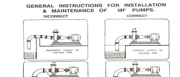
5 GENERAL INSTRUCTIONS FOR INSTALLATION, OPERATION & MAINTENANCE OF M F PUMPS WARNING The equipment supplied is designed for specific capacity, speed, pressure and temperature. Do not use the equipment beyond the capacities for which it is manufactured. The equipment manufactured is also shop tested for the satisfactory performance and if it is operated is excess of the conditions for which it is manufactured the equipment will be subject to excessive stresses and strains. LOCATION The pump should be located as near the liquid source as possible. This will minimise the suction lift an d pump will give better performance. Ample space should be provided on all the sided so that the pump can be inspected while in operation and can be serviced conveniently whenever required. FOUNDATION The foundation should be sufficiently substantial to absorb any vibration and to form a permanent rigid support for the base plate. This is important in maintaining the alignment of a direct connected unit. A concrete foundation on a solid base is advisable. Foundation bolts of the proper size should be embedded in the concrete located by a drawing or template. A pipe sleeve about two and one-half diameter larger than the bolt should be used to allow movement for the final position of the foundation bolts. ALIGNMENT Pumps and drivers that are supplied by the manufacturers, mounted on a common base plate are accurately aligned before dispatch. However the base plats are flexible to some extent and therefore must not be relied upon to maintain the factory alignment. Re-alignment is necessary after the complete plete unit has been leveled on the foundation and again after the grout has been set and the foundation bolts has been tightened. The alignment must be checked after the unit is piped up and rechecked periodically. FLEXIBLE COUPLING A Flexible coupling will not compensate for misalignment of the pump and driver shafts. The purpose of the flexible coupling is to compensate for the temperature changes and to permit the movement of the shafts without interference with each other while transmitting power from the driver to the pump.
6 TYPE OF MISALIGNMENT (SEE FIGURE 1) There are two types of misalignment between the pump shaft and the driver shaft. (a) Angular misalignment : Shafts with axis concentric but not parallel (b) Parallel misalignment : Shafts with axis parallel but not concentric LEVELLING THE UNIT When the unit is received with the pump and the driver mounted on the base plate, it should be placed on the foundation and the coupling halves disconnected. The coupling should not be reconnected until all alignment operations have been completed. The base plate must be supported evenly on wedges inserted under the four corners so that it will not be distorted or sprung by the uneven distribution of the weight. Adjust the wedges until the shaft of the pump and drivers are in level. Check the coupling faces, suction and discharged flanges for the horizontal and the vertical positions by means of spirit level. FLEXIBLE COUPLING ALIGNMENT (SEE FIGURE 2) The two halves of the coupling should be atleast 4 mm apart so that they cannot touch each other when the driver shaft is rotated. Necessary tools for approximately checking are straight edge and on an outside caliper. A check for parallel alignment is made by placing a straight-edge across both coupling periphery at the top, bottom and bolt sides. The unit will be in parallel alignment when the straight-edge rests evenly on the coupling periphery at all positions. Care must be taken to have the straight-edge parallel to the axis of the shafts. A check for angular alignment is made by using an outside caliper across the width of the coupling faces at various points. Coupling alignment can be checked with dia gauge indicator as shown in figure 2. GROUTING When the alignment is correct, the foundation bolts should be tightened evenly but not too firmly. The unit can then be grouted by working soft concrete under the edges Foundation bolts should not be fully tightend until the grout is hardened usually 48 hours after pouring. FACTORS THAT MAY DISTURB ALIGNMENT The unit should be periodically checked for alignment. If the unit does not stay in line after being properly installed, the following are possible causes (a) Setting, seasoning of the foundation. (b) Pipe strains distorting or shifting the machines. (c) Wear of the bearings.
7 PIPING Both suction and delivery pipes and accessories should be independently supported near the pump so that when the flange bolts are tightend no strain will be transmitted to the pump casing. It is usually advisable to increase the size of both suction and delivery pipes at the pump nozzles in order to decrease the loss of head from friction and for the same reason piping should be arranged with as minimum bends as possible, as these should be made with a long radius wherever possible. The pipe lines should be free from scales, welding residuals etc., and have to be mounted in such a way that they can be connected to suction and delivery flanges without any stress on the pump. Adequate supports should be given to the pipe lines so that the weight of the pipe lines does not fall on the pumps. The use of the minimum number of the bends and other fittings will minimise the frictional losses. SUCTION PIPE The suction pipe should be as short as possible. This can be achieved by placing the pump near the liquid to be pumped. The suction pipe must be kept free from air leaks. This is particularly important when the suction lift is high. A horizontal suction line must have a gradual rise to the pump. Any high point in the pipe will be filled with the air and thus prevent proper operation of the pump. A concentric taper piece should not be used in a horizontal suction line as it forms an air pocket in the top of the reducer and the pipe. Use an eccentric piece instead. The end of the suction pipe must be well submerged to avoid whirlpools and ingress of air but must be kept clear of any deposits of mud, silt grit etc. The pipe must be clear from any side of the wall by atleast 450 mm. The end of the suction pipe should be provided with the strainer of sufficient open area. DELIVERY PIPE A check (non-return) valve and a gate of sluice valve (regulating valve) should be installed in the discharge line. The check valve placed between the pump and the gate valve is to protect the pump from excessive pressure and to prevent water running back through the pump in case of failure of the driving machine. Discharge piping should be provided with the sluice valve adjacent to the delivery flange to control the discharge, if required. SEALING Apply sealing liquid (external sealing) to the shaft seal cage to prevent entry of air in the case of pumps with packed stuffing box. It is convenient to tap the sealing liquid from the delivery line above the non- return valve. FOOT VALVE It is advisable to install a foot valve to facilitate priming. The foot valve should have sufficient clear passage of water. Care must be taken to prevent foreign matter from being drawn into the pump or choking the foot valve and for this purpose an efficient strainer should be provided. STUFFING BOXES AND PACKING Stuffing boxes should be carefully cleaned and the packing placed in them. Be sure that sufficient packing is placed at the back of the water seal cage. If the water to be pumped is dirty or grity, sealing water should be piped to the stuffing boxes from clean outside source of supply in order to prevent damage to the packing and shaft.' In placing the packing, each packing ring should be cut to the proper length so that ends come together but do not overlap. The succeeding rings of packing should not be pressed too tight as it may result in burning the packing and cutting the shaft. If the stuffing box is not properly packed, friction in stiffing box prevents turning the rotor by hand. On starting the pump it is well to have the packing slightly loose without causing an air leak, and if it seems to leak, instead of putting too much pressure on the gland, put some heavy oil in the stuffing box until the pump works properly and then gradually tighten up the gland. The packing should be occasionally changed.
8 BALL BEARINGS Correct maintenance of ball bearings essential. The bearing manufacturers give the following as a guide to relubrication periods under normal conditions. Three monthly when on continous duty. Six monthly when on eight-hour per day duty. The bearings and housings should be completely cleaned and recharged with fresh grease after 2500 hours or the nearest pump overhaul time. PRIMING No pumping action occurs unless the pump casing is filled with liquid. Pump casing and suction pipe must therefore be completely filled with the liquid and thus all air removed before the pump is started. Several different priming methods can be used depending on the kind of installation and service involved. (1) Liquid level above pump level. Pump is set below liquid level of source of supply so that liquid always flows to pump under positive head. (2) Priming with foot valve. (a) When pump is installed on suction lift with foot valve at the end of suction line, fill pump with water form some outside source till all air is expelled and water flows through air vent. (b) When there is liquid under some pressure in the discharge pipe, priming can be effected by bypassing the pressure liquid around the check and gate valve. Of course, the original prime must be effected from some outside source. NOTE: In this case, the foot valve must be capable of withstanding pump pressure and possible surge. (3) Priming by ejector: An ejector operated by steam, compressed air or water under pressure and connected to air vent on top of casing can be used to remove air form and prime the pump on suction lift installations. (4) Priming by dry vacuum pump: A hand or power pump sucks in all the air form the casing and the suction pipe, and thus primes the system. STARTING The pump must not be started without being primed. Be sure that the driver rotates in the proper direction as indicated by a direction arrow on the pump casing. RUNNING On account of its simple construction, the centrifugal pump requires practically no attention while running. Lubrication of the bearing and manipulation of the glands are the only things that need attention from the operator. STOPPING Before stopping the pump, close the gate valve. This will prevent water hammer on check valve. STUFFING BOXES Do not tighten the glands excessively. A slight dripping of water from the stuffing boxes when pump is running keeps packing in good condition. CASING RINGS Casing rings are fitted in the casing to reduce the quantity of water leaking back from the high pressure side to the suction side. These casing rings are fitted to maintain a small clearance and depend on the water in the pump for lubrication. When they are worn out, the clearance become greater and more water passes back into the suction. They must be replaced form time to time to restore the pump efficiency to its normal value.
9 SPARE PARTS A set of ball bearings, a set of casing rings and a set of gland packing rings must always be kept at hand to ensure uninterrupted service from the pump. While ordering for spare parts, always give type, size and serial number of the pump as stamped on the name plate. Refer ASSY NOS. : MB7-06 & MC7-06 PUMP TROUBLE When investigating trouble with MF pumps, always remember that pumps have been tested at the factory and are mechanically correct when sent out. Discounting the possibility of damage during transit, most of the trouble in the field is due to faulty installations. Investigations show that the majority of troubles with centrifugal pumps result from faulty conditions on the suction side. 1. GENERAL 1.1 This booklet covers instruction for following type of MF pumps. MF 300/400 / MF 250/270 MF 350/500 MF 450/ These are single stage horizontal single volute type foot mounted end suction pumps fitted with oil lubricated ball bearings and thrust bearing, The pumps provided with semi open type mixed flow impeller. The delivery casing can be offered in following TWO different executions. (1) VERTICON - (STANDARD) Pointing Vertically upwards. (2) HORIZON - Pointing Horizontal 1.3 Pumps when properly installed and given due care in operation and maintanence should operate satisfactorily for a long period. 1.4 When the pump is received some time before the actual use of pump. It should be inspected and located in dry place. The coupling should be rotated once in a month to prevent pitting of bearing surfaces. 1.5 The special problems arising at site should be referred to the supplier full name plate details should be furnished while exchanging correspondence in connection with these pumps. 2. INSTALLATION 2.1 For location, preparing foundation, installation, alignment, general maintenance, trouble shooting etc. the instructions given in our publication 'General Instruction Manual on centrifugal pumps' which is printed along with this manual must be followed carefully. 2.2 The external sealing connection to the pump if applicable, must be made after installing and before commissioning of pump.
10 3. OPERATION 3.1 Before starting the pump check the following The pump rotates freely Sealing connections if any is properly tightened and adjusted Oil level in the bearing housing The direction of rotation of motor corresponds to the direction of rotation of the pump The pump and suction pipe is fully primed with the liquid Stuffing box is packed properly and gland is tightened Valve on delivery side is closed The cock for pressure gauge connection is closed. 3.2 Starting the pump Open delivery valve 30% approx. of full open Start the motor. Let the prime mover pick up its full speed Open the valve on the delivery side fully Open the cock for pressure gauge connection. 3.3 During running of pump, check the following and regulate if necessary The pump and motor is running smooth The flow of sealing liquid is uninterrupted if external sealing is applicable Leakage through stuffing box is normal there should be leakage of 60 to 80 drops per minute The bearings not getting heated up excessively Head and capacity developed by the pump is as specified Power consumption is within limit Ensure that there is no mechanical friction in the pump Stop the pump immediately if any defects are noticed. DO NOT START IT AGAIN UNLESS DEFECTS ARE RECTIFIED. REPORT IMMEDIATELY TO THE SUPPLIER IF IT IS NOT POSSIBLE TO RECTIFY THE DEFECTS. 3.4 During stopping the pump Close the valve on the delivery side Stop the motor Close the sealing connection If the pump is not required to be operated for long time drain the casing completely. Also drain the lubrication oil completely. The bearing housing should be dried internally with hot air and should be flushed with moisture free protective such as light oil or kerosene..
11 4. TECHNICAL DATA 4.1 Direction of rotation The standard direction of rotation is clockwise when viewed form driving ends. The pump with the reverse direction of rotation is not possible. 4.2 Bearings The pumps are fitted with antifriction heavy duty single row deep groove ball bearing at driving and non driving end. Also a thrust bearing is provided at DE to take residual axial thrust. The details of bearings are given in Technical chart 1. The designation of bearings is as per SKF catalogue. However, equivalent bearings in type, capacity and dimensions also can be used. 4.3 Lubrication Bearings are oil lubricated. The oil used should be a highly refined straight mineral product of high emulsibility free from running and acid forming tendencies. Detergent oil may cause foaming and emulsion difficulties and should not be used. The oil should be conform to the following grades of oil available in the market. Manufacturers INDIAN OIL HINDUSTAN PETROLEUM CALTEX Trade name SERVOSYSTEM-317 ENCLO-53 REGAL OIL B (R&O) 4.4 Refilling Period For a new pump oil is to be changed after 200 hours of working. For subsequent filling, the oil is to be hanged after about 1000 hours of working. 4.5 Bearing Temperature The maximum allowable bearing temperature is 80 C. 4.6 Stuffing box The stuffing boxes are extra deep to reduce leakage and minimise the maintenance. Lantern ring is provided for sealing purpose. 4.7 Sealing Self liquid is only used for sealing in most of the cases. However sealing arrangement with external liquid can be supplied against specific request. 4.8 Stuffing box packing Teflon Impregnated Graphited Asbestos (TIGA) is used in the standard supply. However packing suitable for liquid handled is also supplied against order. 4.9 Flexible coupling The pumps are supplied with pin and rubber bush type flexible couplings for the sizes and the quantity of rubber bushes. Please refer to technical data I.
12 5. MAINTENANCE Preventive maintenance schedule is the periodical checks and precautions by which possibility of failure and breakdowns are made very remote. 5.1 Daily Checks Pressure gauge readings Bearing temperature Oil level in bearing housing Leakage through s1. Box Noise and vibrations Voltage and current 5.2 Periodical maintenance Check the alignment of pump set Calibrate the measuring instruments Check the sealing connections 6. OVERHAULING With normal daily operating spell, the pump will be due for overhaul after about 5000 working hours. This work should be done by skilled personnel. Please refer to the cross sectional drawing while dismantling and reassembling the pump. 6.1 Dismantling (Please refer Assy Drg. No. MC7-06 & MB7-06) Drain the volute casing (11.4) completely by removing drain pump (91.5) Disconnect the pump from suction and delivery piping and auxiliary piping if any. Remove coupling nuts and take out coupling pins along with rubber bushes and coupling washer. Unscrew the bolts holding the pump on base plate and take out the pump. Drain oil from bearing bed (36.7) by unscrewing the drain plug (91.38) Remove oil level indicator (65.23)n and accessories. Remove pump coupling. Take out coupling key (95.2) Remove the nuts holding down suction adopter (18.01) form volute casing (11.4). Take out suction adopter by tightening release bolts. Take O rings (42.4) from suction adopter (18.01) Unscrew impeller nut (93.4). Take out the lock washer for impeller nut (94.04) Remove the impeller (24.2) from pump shaft (22.3)
13 6.1.7 Take out impeller key (95.12) Remove nuts holding down bearing bed (36.7) to the volute casing (11.4)and take it out carefully Unscrew gland nuts and remove gland (46.4). Take out gland packing (47.3) and lantern ring (46.10) Remove the stuffing box bush (46.41) from volute casing by removing hexagonal bolts. The stuffing box bush is not provided in pumps type MF 300/400 and MF 350/ Remove Shaft sleeve (53.6) O Ring (42.41) and key for impeller and shaft sleeve (95.12). Take out deflector (51.9) Remove outer bearing cap (37.2) along with oil seal (43.3) removing bolts and by tightening release bolts. Also remove inner bearing cap (37.3) along with oil seal (43.13) by unscrewing bolts Take out pump shaft (22.3) from bearing bed along with bearing lock nut bearing nut (93.3) ball bearing DE (33.3) thrust bearing (33.13) bearing adopter (37.21) and ball bearing NDE (33.3) Unscrew lock nut and bearing nut (93.3) Remove whole assembly that is bearing adopter, ball bearing D.E., thrust bearing by using suitable puller or bearing adopter (37.21) Remove ball bearing NDE (33.3) and take out bearing spacer (33.6) this completes the dismantling of the pump. Before proceeding of reassembly of rotating unit and pump check the following a) Ball bearing are rotating freely and smoothly. Renew them if they are not rotating freely or if the races are deteriorated. b) Check the shaft for possible run out. Remove the same before reassembling. c) Remove any dust or rust form parts and if necessary apply new paint/coating on the same. d) Clean all the parts thoroughly with kerosene or petrol. e) If reassembling is not to be made immediately, apply rust preventive coating on al machined surfaces. f) Examine all the pars for refitting, worn out etc. Damaged or corroded parts should be replaced by new. g) Ensure that newly fitted parts are free form damage and from burrs. h) Examine deflector O Ring for damage or deterioration. If replaced with new make sure that they are of requisite dimensions.
14 6.2 Reassembly Wipe light clean oil over shaft (22.3) Insert bearing spacer (33.6) from NDE and fit ball bearing NDE (33.3) Put compression springs for thrust bearing (33.13) in the holes provided into bearing adopter (37.21). Fit the cage of thrust bearing (33.13) into bearing adopter. Fit another cage of thrust bearing on thrust bearing adopter (33.5) on the shaft Fit ball bearing (33.3) at D.E AND N.D.E. Ensure that bearing spacer (33.6) is fitted at NDE prior to ball bearing. Fit bearing nut and lock it by means of bearing lock nut (93.3). Fit gasket (41.06) on bearing adopter (37.21) Lift the shaft (22.3) duly fitted with bearings and insert it in bearing bed (36.7) Fit outer bearing cap (37.2) and inner bearing cap (37.3). Ensure that gasket (41.05) & (41.07) is duly fitted and shaft is rotated freely Insert deflector (51.9) and gland (46.4) from shaft Fit bearing housing (36.7) to the volute casing (11.4) and tighten the nuts Fit shaft sleeve (53.6) along with '0' ring (42.41) and insert key for impeller and shaft sleeve (95.12). Ensure that '0' ring (42.41) is fitted properly. Fit gasket (41.08) Fit impeller key (95.12) and fit the impeller (24.2) Insert lock washer for impeller nut (94.04) over the pump shaft (22.3) and tighten impeller nut (93.4). Lock the impeller nut by means of lock washer Ensure that impeller rotates freely. Fit suction adopter (18.01) duly fitted with O Ring (42.4) to volute casing (11.4) and tighten the nuts. Ensure that the pump shaft rotates freely Insert gland packing (47.3) along with lantern ring (46.10) and tighten the gland. Do not Over tighten it Fit coupling key (95.2) and fit pump coupling over shaft Install the pump on base plate and make suction and delivery as well as auxiliary pipe Connections Fill the oil in bearing bed. Align motor coupling with pump coupling and fix coupling pins and nuts along with rubber bushes and coupling washers. This completes the reassembly of the pump.
15


16

17
18 BREAKDOWN - CAUSE - CHECK POINTS In case of breakdown we recommand the location of the fault by using the following table. BREAKDOWN CHECK-POINTS Pump does not deliver Pump delivers at reduced capacity Delivery performance deteriorates Pump delivers too much Delivery is interrupted After stopping pump runs in reverse direction 52 Very noisy Unsteady running of pump Stuffing box leaks excessively Fumes from stuffing box Pump rotor locked in Standstill position. Pump is heating up and seizing Bearing temperature increases Motor will not start Motor gets hot or burns out Motor is difficult to start
19 CHECK POINTS 1 Suction pipe, foot valve chocked. 2 Nominal diameter of suction line too small. 3 Suction pipe not sufficiently submerged. 4 Too many bends in the suction line. 5 Clearance around suction inlet not sufficient. 6 Shut off valve in the suction line in unfavourable position. 7 Incorrect layout of suction line (formation of air pockets). 8 Valve in the suction line not fully open. 9 Joints in the suction line not leak-proof. 10 Air leaking through the suction line and stuffing box etc. 11 Suction lift too high. 12 Suction head too low (difference between pressure at suction connection and vapour pressure too low). 13 Delivery liquid contains too much gas and / or air. 14 Delivery liquid too viscous. 15 Insufficient venting. 16 Number of revolutions too high. 17 Number of revolutions too low. 18 Incorrect direction of rotation (electric motor incorrectly connected, leads of phases on the terminal m interchanged). 19 Impeller clogged. 20 Impeller damaged. 21 Casing rings worn out. block 22 Seperation of crystals from the flow of pumping liquid (falling below the temperature limit / equilibrium temperature). 23 Sealing liquid line obstructed. 24 Sealing liquid contaminated. 25 Lantern ring in the stuffing box is not positioned below the sealing liquid inlet. 26 Sealing liquid omitted. 27 Packing incorrectly fitted. 28 Gland tightened too much / slanted. 29 Packing not suitable for operating conditions. 30 Shaft sleeve worn in the region of the packing. 31 Bearing worn out. 32 Specified oil level not maintained. 33 Insufficient lubrication of bearings. 34 Ball bearings over-lubricated. 35 Oil/Grease quality unsuitable. 36 Ball bearing incorrectly fitted. 37 Axial stress on ball bearings no axial clearance for rotor).
20 38 Bearings dirty. 39 Bearings rusty (corroded). 40 Axial thrust too great because of worn casing rings, relief holes obstructed. 41 Insufficient cooling water supply to stuffing box cooling. 42 Sediment in the cooling water chamber of stuffing box cooling. 43 Alignment of coupling faulty or coupling loose. 44 Elastic element of coupling worn. 45 Pump casing under stress. 46 Pipe line under stress. 47 Shaft runs untrue. 48 Shaft bend. 49 Rotor parts insufficiently balanced. 50 Rotor parts touching the casing. 51 Vibration of pipe work. 52 Non-return valve gets caught. 53 Contaminated delivery liquid. 54 Obstruction in the delivery line. 55 Delivery flow too great. 56 Pump unsuitable for parallel operation. 57 Type of pump unsuitable. 58 Incorrect choice of pump for existing operating condition. 59 Voltage too low / power supply overloaded. 60 Short circuit in the motor. 61 Setting of starter of motor too high 62 Temperature of delivery liquid too high.
INSTRUCTIONS ON INSTALLATION OPERATION AND MAINTENANCE FOR KIRLOSKAR PUMP TYPE DB
 INSTRUCTIONS ON INSTALLATION OPERATION AND MAINTENANCE FOR KIRLOSKAR PUMP TYPE DB KIRLOSKAR BROTHERS LIMITED UDYOG BHAVAN, TILAK ROAD, PUNE - 4 002 KIRLOSKAR BROTHERS LIMITED Udyog Bhavan, Tilak Road,
HORIZONTAL SPLIT CASING PUMP
 OPERATION & MAINTENANCE MANUAL HORIZONTAL SPLIT CASING A Mark of Quality CROSS SECTION DRAWING No. DESCRIPTION MATERIAL 01 1/4 BSP PLUG BRASS 02 LOWER HOUSING C. I. IS-210, FG260 03 IMPELLER C. I. / G.
INSTRUCTIONS ON INSTALLATION OPERATION AND MAINTENANCE FOR KIRLOSKAR PUMP TYPE DSM (STANDARD)
") INSTRUCTIONS ON INSTALLATION OPERATION AND MAINTENANCE FOR KIRLOSKAR PUMP TYPE DSM (STANDARD) KIRLOSKAR BROTHERS LIMITED UDYOG BHAVAN, TILAK ROAD, PUNE - 4 00 KIRLOSKAR BROTHERS LIMITED Udyog Bhavan, Tilak
INSTRUCTIONS ON INSTALLATION OPERATION AND MAINTENANCE FOR KIRLOSKAR PUMP TYPE DSM (STANDARD) KIRLOSKAR BROTHERS LIMITED UDYOG BHAVAN, TILAK ROAD, PUNE - 4 00 KIRLOSKAR BROTHERS LIMITED Udyog Bhavan, Tilak
Series Base mounted pump. Installation and operating instructions
 Series 4030 Installation and File No: 40.80 Date: june 25, 2015 Supersedes: 40.80 Date: october 10, 2009 contents General 4 Inspection 4 Installation - Series 4030 base mounted Pump 4 1.0 Location 4 2.0
PROCESS PUMPS (INDIA) PVT LTD
 PVT LTD") MANUAL: - M10 HORIZONTAL BPO METALLIC PUMP WITH EXTERNAL MECHANICAL SEAL (GROUP- III & IV) INSTALLATION, OPERATION AND MAINTENANCE MANUAL PROCESS PUMPS (INDIA) PVT LTD Plot No.86, III Phase, Peenya Industrial
MANUAL: - M10 HORIZONTAL BPO METALLIC PUMP WITH EXTERNAL MECHANICAL SEAL (GROUP- III & IV) INSTALLATION, OPERATION AND MAINTENANCE MANUAL PROCESS PUMPS (INDIA) PVT LTD Plot No.86, III Phase, Peenya Industrial
SAM TURBO INDUSTRY LIMITED
 INSTRUCTIONS ON INSTALLATION, OPERATION AND MAINTENANACE FOR SAM TURBO PUMP TYPE TCC SAM TURBO INDUSTRY LIMITED NEELAMBUR, COIMBATORE-641 014. INDIA PH: 0422-3058899(50 LINES), FAX: 3058000, E-MAIL: info@sampumps.com,
PROCESS PUMPS (INDIA) PVT LTD
 PVT LTD") MANUAL: - M12 HORIZONTAL BPO METALLIC PUMP WITH GLAND PACKING (GROUP- III & IV) INSTALLATION, OPERATION AND MAINTENANCE MANUAL PROCESS PUMPS (INDIA) PVT LTD Plot No.86, III Phase, Peenya Industrial Area,
MANUAL: - M12 HORIZONTAL BPO METALLIC PUMP WITH GLAND PACKING (GROUP- III & IV) INSTALLATION, OPERATION AND MAINTENANCE MANUAL PROCESS PUMPS (INDIA) PVT LTD Plot No.86, III Phase, Peenya Industrial Area,
PROCESS PUMPS (INDIA) PVT LTD
 PVT LTD") HYDRODYNAMIC SEAL NON METALLIC PUMP INSTALLATION, OPERATION AND MAINTENANCE MANUAL PROCESS PUMPS (INDIA) PVT LTD Plot No.86, III Phase, Peenya Industrial Area, Bangalore 560058 Phone: 91-80-28395327/28
HYDRODYNAMIC SEAL NON METALLIC PUMP INSTALLATION, OPERATION AND MAINTENANCE MANUAL PROCESS PUMPS (INDIA) PVT LTD Plot No.86, III Phase, Peenya Industrial Area, Bangalore 560058 Phone: 91-80-28395327/28
INSTALLATION, OPERATION AND MAINTENANCE INSTRUCTIONS
 INSTALLATION, OPERATION AND MAINTENANCE INSTRUCTIONS Contents Section 1. General Observations... 2 2. Operation... 4 3. Control During Operation... 5 4. Trouble Shooting... 6 5. Maintenance... 7 Please
Series Base mounted pump. Installation and operating instructions
 Series 4030 Installation and File No: 40.80 Date: december 12, 2016 Supersedes: 40.80 Date: july 27, 2016 contents General 4 Inspection 4 Installation - Series 4030 base mounted Pump 4 1.0 Location 4
SERIES PC INSTRUCTION AND OPERATION MANUAL
 MEGGA SERIES PC INSTRUCTION AND OPERATION MANUAL Models PCT and PCF Close-coupled and frame-mounted single-stage horizontal end-suction pumps. WARNING: Read this manual before installing or operating this
INSTRUCTIONS ON INSTALLATION OPERATION AND MAINTENANCE FOR KIRLOSKAR PUMP TYPE SHM
 INSTRUCTIONS ON INSTALLATION OPERATION AND MAINTENANCE FOR KIRLOSKAR PUMP TYPE SHM KIRLOSKAR BROTHERS LIMITED UDYOG BHAVAN, TILAK ROAD, PUNE - 00 KIRLOSKAR BROTHERS LIMITED Udyog Bhavan, Tilak Road, Pune
PROCESS PUMPS (INDIA) PVT LTD
 PVT LTD") MANUAL: - NM3 HORIZONTAL BPO NON METALLIC PUMP WITH DOUBLE MECHANICAL SEAL GROUP 0 INSTALLATION, OPERATION AND MAINTENANCE MANUAL PROCESS PUMPS (INDIA) PVT LTD Plot No.86, III Phase, Peenya Industrial
MANUAL: - NM3 HORIZONTAL BPO NON METALLIC PUMP WITH DOUBLE MECHANICAL SEAL GROUP 0 INSTALLATION, OPERATION AND MAINTENANCE MANUAL PROCESS PUMPS (INDIA) PVT LTD Plot No.86, III Phase, Peenya Industrial
PROCESS PUMPS (INDIA) PVT LTD
 PVT LTD") VERTICAL CANTILEVER SHAFT SUMP PUMP (PPCS)_ METALLIC INSTALLATION, OPERATION AND MAINTENANCE MANUAL PROCESS PUMPS (INDIA) PVT LTD Plot No.86, III Phase, Peenya Industrial Area, Bangalore 560058 Phone:
VERTICAL CANTILEVER SHAFT SUMP PUMP (PPCS)_ METALLIC INSTALLATION, OPERATION AND MAINTENANCE MANUAL PROCESS PUMPS (INDIA) PVT LTD Plot No.86, III Phase, Peenya Industrial Area, Bangalore 560058 Phone:
Enriching Lives T E C H N I C A L M A N U A L DV-40/DV-50 SERIES. KIRLOSKAR BROTHERS LIMITED A Kirloskar Group Company TM 1002
 Enriching Lives T E C H N I C A L M A N U A L DV-40/DV-50 SERIES KIRLOSKAR BROTHERS LIMITED A Kirloskar Group Company TM 00 Our products are meant for pumping water and they do not have any significant
Installation Vertical Pump: Installation 'CM' and 'CDM' Style: Operation:
 Installation Vertical Pump: Gusher vertical end suction pumps with integral shaft is easily installed and put into service. With the one piece shaft design there is no couplings to align, no shims or no
INSTRUCTIONS ON INSTALLATION, OPERATION AND MAINTENANCE FOR KIRLOSKAR PUMP TYPE RKB
 INSTRUCTIONS ON INSTALLATION, OPERATION AND MAINTENANCE FOR KIRLOSKAR PUMP TYPE RKB 1 WARRANTY We warrant that the pump supplied from us is free from defective material and faulty workmanship. This warranty
SAM TURBO INDUSTRY LIMITED
 INSTRUCTIONS ON INSTALLATION, OPERATION AND MAINTENANACE FOR SAM TURBO PUMP TYPE CPC SAM TURBO INDUSTRY LIMITED NEELAMBUR, COIMBATORE-641 014. INDIA PH: 0422-3058899(50 LINES), FAX: 3058000, E-MAIL: info@sampumps.com,
DISASSEMBLY AND ASSEMBLY INSTRUCTIONS FOR LIQUID RING VACUUM PUMPS
 (Rev. 2.0_10-2010) DISASSEMBLY AND ASSEMBLY INSTRUCTIONS FOR LIQUID RING VACUUM PUMPS TRVK 2003 to 5003 TRSK 2005 to 5005 INTRODUCTION These instructions are for the maintenance staff in case of repair
SAM TURBO INDUSTRY LIMITED
 INSTRUCTIONS ON INSTALLATION, OPERATION AND MAINTENANACE FOR SAM TURBO PUMP TYPE ZM SAM TURBO INDUSTRY LIMITED NEELAMBUR, COIMBATORE-641 014. INDIA PH: 0422-3058899(50 LINES), FAX: 3058000, E-MAIL: mktg@sampumps.com,
1750 RPM Centrifugal Pumps
 Please read and save this Repair Parts Manual. Read this manual and the General Operating Instructions carefully before attempting to assemble, install, operate or maintain the product described. Protect
ISO 9001 CERTIFIED COMPANY INDUSTRIAL PUMPS. Installation & Operational Manual For BACK-PULL-OUT PUMP
 ISO 9001 CETIFIE COPANY Installation & Operational anual For BACK--OT P EX Assembly isassembly Erection Starting unning Stopping and aintenance Cautions in use of echanical Seal Stuffing Box and Packing
INSTRUCTION MANUAL INTERNAL GEAR PUMP TITAN G-4124A SERIES=> FLANGED TITAN G-124A SERIES => FLANGED MODELS:
 INSTRUCTION MANUAL INTERNAL GEAR PUMP TITAN G-4124A SERIES=> FLANGED TITAN G-124A SERIES => FLANGED MODELS: G-H, G-HL, G-K, G-KK, G-L, G-LQ, G-LL, GLS, G-Q, G-QS 1 Contents Maintenance Thrust bearing adjustment
1750 RPM Centrifugal Pumps
 Please read and save this Repair Parts Manual. Read this manual and the General Operating Instructions carefully before attempting to assemble, install, operate or maintain the product described. Protect
NECO Pumping Systems
 INSTALLATION OPERATION & MAINTENANCE INSTRUCTIONS For Your NECO Pumping Systems Fuel Oil Transfer System THIS COMPLETELY ASSEMBLED, TESTED, PACKAGED SYSTEM IS OF THE HIGHEST QUALITY AND DESIGN. TO OBTAIN
CSO / CP PUMPS Vertical Spindle Type Installation, Operation and Maintenance Manual
 CSO / CP PUMPS Vertical Spindle Type Installation, Operation and Maintenance Manual www.sameng.co.za (011) 823 4250 Proud Manufacturers of SAMCO Pumps Contents INTRODUCTION 3 LOCATION OF UNIT 3 INSTALLATION
INSTRUCTIONS Installation Operation Repair
 Peerless Pump Company 2005 Dr. M.L. King Jr. Street, P.O. Box 7026, Indianapolis, IN 46207-7026, USA Telephone: (317) 925-9661 Fax: (317) 924-7338 www.peerlesspump.com www.epumpdoctor.com INSTRUCTIONS
SERIES G3DB/AG3DB ELEVATOR
 TM INSTRUCTIONS AND PARTS LIST SERIES G3DB/AG3DB ELEVATOR WARNING This manual, and GENERAL INSTRUCTIONS MANUAL, CA-1, should be read thoroughly prior to pump installation, operation or maintenance. SRM00059
INSTRUCTION, INSTALLATION, MAINTENANCE AND REPAIR MANUAL MODEL 3310
 SECTION 6 ITEM 3310 DATED JUNE 1, 2007 INSTRUCTION, INSTALLATION, MAINTENANCE AND REPAIR MANUAL 6 MODEL 3310 IMPORTANT NOTE TO INSTALLER: This manual contains important information about the installation,
Impeller Replacement
 Impeller Replacement Threaded Shaft Frame Mount H 806 Clockwise Rotation Volute shown. 1149 0794 1 Unfasten hardware holding volute to bracket. Remove volute to expose impeller. Peel off old volute gasket
SAM TURBO INDUSTRY LIMITED
 INSTRUCTIONS ON INSTALLATION, OPERATION AND MAINTENANACE FOR SAM TURBO PUMP TYPE AR SAM TURBO INDUSTRY LIMITED NEELAMBUR, COIMBATORE-641 014. INDIA PH: 0422-3058899(50 LINES), FAX: 3058000, E-MAIL: info@sampumps.com,
TECHNICAL SERVICE MANUAL INSTALLATION, START UP, TROUBLESHOOTING, SERIES SG-04, SG-05 & SG-07 spur gear PUMPS
 Electronic copies of the most current TSM issue can be found on the Viking Pump website at www.vikingpump.com TECHNICAL SERVICE MANUAL SECTION TSM 340 PAGE 1 OF 10 ISSUE G INSTALLATION, START UP, TROUBLESHOOTING,
PROJ. NO SECTION HYDRONIC PUMPS
 SECTION 23 21 23 HYDRONIC PUMPS PART 1 - GENERAL 1.1 RELATED DOCUMENTS A. Drawings and general provisions of the Contract, including General and Supplementary Conditions and Division 01 Specification Sections,
Medium and high pressure pumps
 Screw pumps Medium and high pressure pumps Installation and Start-up Instruction This instruction is valid for all standard high pressure pumps: E4, D4 and D6 Contents Page Pump identification 2 Installation
The ELM Series Slurry Pump Installation and Operating Manual
 The ELM Series Slurry Pump Installation and Operating Manual Excellence Pump Industry Co., Ltd. SAFETY INFORMATION The following safety information relating to pump operation and maintenance should be
WARMAN PUMPS ASSEMBLY, OPERATING AND MAINTENANCE INSTRUCTIONS PART 2C SERIES A SOLUTION PUMPS TYPE S AND SH PC2C
 WARMAN PUMPS ASSEMBLY, OPERATING AND MAINTENANCE INSTRUCTIONS SERIES A SOLUTION PUMPS TYPE S AND SH PC2C WARMAN PUMPS ASSEMBLY, OPERATING AND MAINTENANCE INSTRUCTIONS SERIES A SOLUTION PUMPS TYPE S AND
INSTRUCTION MANUAL AC2516 REVISION D INSTALLER: PLEASE LEAVE THIS MANUAL FOR THE OWNER S USE. Series 1580 In-Line Mounted Centrifugal Fire Pumps
 INSTRUCTION MANUAL AC2516 REVISION D INSTALLER: PLEASE LEAVE THIS MANUAL FOR THE OWNER S USE. Series 1580 In-Line Mounted Centrifugal Fire Pumps PUMP LOCATION Locate the pump so there is sufficient room
FOR ROTARY TYPE TWIN GEAR. Pump Type: HGSX
 FOR ROTARY TYPE TWIN GEAR Pump Type: HGSX MODEL : CLIENT : PROJECT : P.O. NO. : SR. NO. : W.O. No. : MANUFACTURER : DEL Pd PUMPS & GEARS PVT LTD. HEAD OFFICE & WORKS : PLOT NO: 113, GIDC ESTATE, WADHWANCITY
Agri KAM INSTALLATION, OPERATION AND MAINTENANCE MANUAL. A View of KBL Dewas Manufacturing Plant. A Kirloskar Group Company KIRLOSKAR BROTHERS LIMITED
 A View of KBL Dewas Manufacturing Plant KIRLOSKAR Agri KAM MONOBLOC KIRLOSKAR BROTHERS LIMITED A Kirloskar Group Company CORPORATE OFFICE : YAMUNA, Survey No. 98 (-7), Baner, Pune 411 045 (India) Phone
INSTRUCTIONS ON INSTALLATION OPERATION AND MAINTENANCE FOR KIRLOSKAR MULTISTAGE PUMP TYPE KPDS ALL MODELS UDYOG BHAVAN, TILAK ROAD, PUNE
 INSTRUCTIONS ON INSTALLATION OPERATION AND MAINTENANCE FOR KIRLOSKAR MULTISTAGE PUMP TYPE KPDS ALL MODELS KIRLOSKAR BROTHERS LIMITED UDYOG BHAVAN, TILAK ROAD, PUNE - 411 002 KIRLOSKAR BROTHERS LIMITED
SAM TURBO INDUSTRY PVT LIMITED
 INSTRUCTIONS ON INSTALLATION, OPERATION AND MAINTENANACE FOR SAM TURBO PUMP TYPE TCH+N SAM TURBO INDUSTRY PVT LIMITED NEELAMBUR, COIMBATORE-641014, INDIA 1 EXTRA HEAVY DUTY CHEMICAL PROCESS PUMPS AMERICAN
End Suction Centrifugal
 M o d e l s 3 U / 3 U B End Suction Centrifugal Operating Instructions, Installation & Maintenance Manual Certified to NSF/ANSI 6, ANNEX G * NSF/ANSI 6 Annex G listed models: 3U EBARA International Corporation
INSTALLATION AND SERVICE INSTRUCTIONS FOR 1008 AND 1010 SERIES PUMPS
 Service Instruction No. 11 INSTALLATION AND SERVICE INSTRUCTIONS FOR 1008 AND 1010 SERIES PUMPS GENERAL DESCRIPTION Pumping Principles Page 2 INSTALLATION Location Page 3 Proper Installation Page 3 Filter
PROMAG SR SERIES SEAL-LESS CENTRIFUGAL PUMPS
 PROMAG SR SERIES SEAL-LESS CENTRIFUGAL PUMPS INSTALLATION, OPERATION, AND MAINTENANCE INSTRUCTIONS TO OBTAIN THE BEST PERFORMANCE FROM YOUR PROMAG SR PUMP, PLEASE READ THE MANUAL CAREFULLY. Failure to
GENERAL DIMENSIONS OF SMF PUMPS. Capacity upto 7,000 m /hr Head upto 45 m. Range :
 Fluid Technology from Holland GENERAL DIMENSIONS OF SMF PUMPS Features : Closed or Semi-open Impeller Different Orientation of Delivery Nozzle. Vertical Execution The SMF series are single-stage centrifugal
Maintenance Instructions
 General Note These instructions contain information common to more than one model of Bevel Gear Drive. To simplify reading, similar models have been grouped as follows: GROUP 1 Models 11, 0, 1,, (illustrated),,
OPERATION, MAINTENANCE AND OVERHAUL INSTRUCTIONS FOR PB18 SERIES PORTABLE PUMPS
 WATEROUS COMPANY Form No. F 2058 South St. Paul, Minnesota 55075 January, 1992 OPERATION, MAINTENANCE AND OVERHAUL INSTRUCTIONS FOR PB18 SERIES PORTABLE PUMPS Printed in U.S.A. Waterous Company F 2058
SERVICE MANUAL 200 SERIES MOTORIZED 20352, 20452, 20551, 20552, AND MODELS
 Section: MOYNO 500 PUMPS Page:1 of 4 Date: March 1, 1998 SERVICE MANUAL MOYNO 500 PUMPS 200 SERIES MOTORIZED 20352, 20452, 20551, 20552, 22051 AND 22052 MODELS DESIGN FEATURES Housing: AISI 316 stainless
TECHNICAL SERVICE MANUAL GENERAL PURPOSE BRACKET MOUNTED PUMPS SERIES 115 MODELS G, GX2, H and HX4
 TECHNICAL SERVICE MANUAL GENERAL PURPOSE BRACKET MOUNTED PUMPS SERIES 115 MODELS G, GX2, H and HX4 SECTION 2 BULLETIN TSM-115-C ISSUE A CONTENTS Special Information 2 Maintenance 2 Packed Pump Breakdown
 INSTRUCTIONS Your Ampco centrifugal pump is a rugged unit designed to provide years of low cost pumping service. There is a small amount of necessary care required to ensure you of this expected long service.
TWO-STAGE HYDRAULIC PUMP. RWP55-IBT-Air
 ORIGINAL INSTRUCTIONS Form No.1000458 5 SPX Corporation 5885 11th Street Rockford, IL 61109-3699 USA Tech. Services: (800) 477-8326 Fax: (800) 765-8326 Order Entry: (800) 541-1418 Fax: (800) 288-7031 Internet
300 SERIES 331, 332, 333, 344, 356 AND 367 MODELS
 Section: MOYNO 500 PUMPS Page: 1 of 8 Date: March 1, 1998 SERVICE MANUAL MOYNO 500 PUMPS 300 SERIES 331, 332, 333, 344, 356 AND 367 MODELS Mechanical Seal Models Packing Gland Models MODELS DESIGN FEATURES
DEWATERING PUMP. Instruction, Installation, Operation and Maintenance Manual. A Mark of Quality. ISO 9001 Certified Company
 Instruction, Installation, Operation and Maintenance Manual DEWATERING PUMP ISO 9001 Certified Company 2016 mbh pumps (gujarat) pvt. ltd. A Mark of Quality CROSS SECTION DRAWING INSTALLATION No. DESCRIPTION
I & M 8000 Series. Ideal Installation Schematic. Preferred Installation. Trouble Shooting
 I & M 8000 Series 3170 Wasson Road Cincinnati, OH 45209 USA Phone 513-533-5600 Fax 513-871-0105 lowflow@richardsind.com www.lowflowvalve.com Installation & Maintenance Instructions for 8000 Series Low
TECHNICAL SERVICE MANUAL GENERAL PURPOSE JACKETED PUMPS SERIES 230 MODELS HX4, KK, LQ, Q, M, N
 CONTENTS TECHNICAL SERVICE MANUAL GENERAL PURPOSE JACKETED PUMPS SERIES 230 MODELS HX4, KK, LQ, Q, M, N SECTION 2 BULLETIN TSM-230-V ISSUE A Special Information 2 Maintenance 2 Packed Pump Breakdown Drawing
INSTRUCTION, INSTALLATION, MAINTENANCE AND REPAIR MANUAL MODELS 3341 AND 3344 END SUCTION PUMPS
 SECTION 6 ITEM 3340 DATED JULY 2005 SUPERSEDES SECTION 6 ITEM 3340 DATED JANUARY 2004 INSTRUCTION, INSTALLATION, MAINTENANCE AND REPAIR MANUAL MODELS 3341 AND 3344 END SUCTION PUMPS 6 IMPORTANT NOTE TO
Starting up hydraulic systems
 General / Installation A hydraulic system that operates economically, safely, and trouble-free requires careful planning, as well as proper installation and start-up. Conscientious maintenance has a considerable
Installation and Service Instructions 1008 & 1010 Size Pumps
 Installation and Service Instructions 1008 & 1010 Size Pumps Excellence at work. Excellence in life. Table of Contents The Pumping Principle 3 Location 3 Proper Installation 3 Filter Protection 4 Startup
MAINTENANCE AND REPAIR INSTRUCTIONS
 MAINTENANCE AND REPAIR INSTRUCTIONS TYPE TH PUMPS Peerless Pump Company Indianapolis IN, 46207-7026 4849357 TABLE OF CONTENTS Maintenance Page 1 & 2 Disassembly Page 5 & 6 Impeller Clearance 3 Reassembly
S3 General Installation
 Wilfley Drylock Assembly General Installation Operating & General Servicing Clearance Settings Safety Precautions Spare Parts Ordering Assembly Instructions Model S3 General Installation Inspection upon
OPERATION MANUAL INTERNAL GEAR PUMP. Models: NG-H, NG-HL, NG-K, NG-KK, NG-L, NG-LQ, NG-LL, NG-LS, NG-Q, NG-QS. Tel: Fax:
 OPERATION MANUAL INTERNAL GEAR PUMP Models: NG-H, NG-HL, NG-K, NG-KK, NG-L, NG-LQ, NG-LL, NG-LS, NG-Q, NG-QS. 1 Contents Pump Designation System Maintenance Thrust bearing adjustment Pressure Relief Valve
OPERATION & MAINTENANCE MANUAL POLDER PUMP. A Mark of Quality
 OPERATION & MAINTENANCE MANUAL POLDER A Mark of Quality CROSS SECTION DRAWING No. DESCRIPTION MATERIAL 01 DELIVERY FLANGE M.S. 02 CABLE GROMENT Ni. RUBBER 03 CABLE STD. 04 GLNAD COVER C.I. IS210FG260 05
PV4 - PIV6. Submersible multistage centrifugal electro-pumps. Installation and maintenance. This manual is to be given to the end user
 Réf. 3483 GB - 4.33/a - 09.2001 This manual is to be given to the end user PV4 - PIV6 Submersible multistage centrifugal Installation and maintenance PV4 - PIV6 1 - GENERAL PV4 and PIV6 series should be
SUMMIT PUMP. Model DSR Single Stage, Double Suction Pumps Installation, Operation, and Maintenance Manual
 SUMMIT PUMP Model DSR Single Stage, Double Suction Pumps Installation, Operation, and Maintenance Manual 2014 by Summit Pump, Inc. All rights reserved. WARRANTY Pumping units assembled by Summit Pump,
TECHNICAL SERVICE MANUAL
 Electronic copies of the most current TSM issue can be found on the Viking Pump website at www.vikingpump.com TECHNICAL SERVICE MANUAL VIKING HELICAL GEAR REDUCERS A, B, AND C SIZES SECTION PAGE ISSUE
PACKING, HANDLING, TRANSPORTING AND STORING MOTORS
 PACKING, HANDLING, TRANSPORTING AND STORING MOTORS Make sure that the shaft of the motor is not loaded in any way and is protected from knocks. Axial loads or shocks may easily damage the bearings inside
I & M Mark 78 Series. Ideal Installation. Start-Up. Installation & Maintenance Instructions for Mark 78 Control Valves (1-1/2-2 )
") I & M Mark 8 Series 0 Wasson Road Cincinnati, OH 4509 USA Phone 5-5-5600 Fax 5-8-005 info@richardsind.com www.jordanvalve.com Installation & Maintenance Instructions for Mark 8 Control Valves (-/ - ) Warning:
I & M Mark 8 Series 0 Wasson Road Cincinnati, OH 4509 USA Phone 5-5-5600 Fax 5-8-005 info@richardsind.com www.jordanvalve.com Installation & Maintenance Instructions for Mark 8 Control Valves (-/ - ) Warning:
NORTHWESTERN UNIVERSITY PROJECT NAME JOB # ISSUED: 03/29/2017
 SECTION 23 2123 - PUMPS PART 1 - GENERAL 1.1 RELATED DOCUMENTS A. Drawings and general provisions of the Contract, including General and Supplementary Conditions and Division 01 Specification Sections,
PR Series Positive Rotary Pumps
 PRSM PR Series Positive Rotary Pumps Models PR, PRE, and PRED CONTENTS Thank you for purchasing a Tri-Clover Product! This manual contains disassembly and assembly instructions, maintenance procedures,
Model 3656/3756. Installation, Operation and Maintenance Instructions. Table of Contents. Owner s Information
 Installation, Operation and Maintenance Instructions Model 656/756 Owner s Information Please fill in information and give this booklet to homeowner. Warranty information is on page 12. Model Number: Serial
SLR / SLR-S/N. Instruction Manual. Walrus America Inc
 SLR / SLR-S/N Instruction Manual Walrus America Inc 1. Installation and Connection 1.1. Pump Installation The pump should be sited in a well ventilated and frost-free position. The distance between pumps-motors
2.- HANDLING OF VALVES BEFORE ASSEMBLY 3.- FITTING THE VALVE TO THE REST OF THE ASSEMBLY 5.- PERIODICAL INSPECTION OF THE VALVE AND MAINTENANCE
 Page 1 of 16 CONTENTS 1.- INTRODUCTION 2.- HANDLING OF VALVES BEFORE ASSEMBLY 3.- FITTING THE VALVE TO THE REST OF THE ASSEMBLY 4.- OPERATION OF A BALL VALVE 5.- PERIODICAL INSPECTION OF THE VALVE AND
I & M Mark 78 Series. Ideal Installation. Start-Up. Installation & Maintenance Instructions for Mark 78 Control Valves (1/2-1 )
") I & M Mark 8 Series 30 Wasson Road Cincinnati, OH 4509 USA Phone 53-533-5600 Fax 53-8-005 info@richardsind.com www.jordanvalve.com Installation & Maintenance Instructions for Mark 8 Control Valves (/ -
I & M Mark 8 Series 30 Wasson Road Cincinnati, OH 4509 USA Phone 53-533-5600 Fax 53-8-005 info@richardsind.com www.jordanvalve.com Installation & Maintenance Instructions for Mark 8 Control Valves (/ -
TECHNICAL SERVICE MANUAL HEAVY-DUTY BRACKET MOUNTED PUMPS SERIES 120 and SERIES 124 MODELS J, K, KK, L, LQ, LL AND LM
 TECHNICAL SERVICE MANUAL HEAVY-DUTY BRACKET MOUNTED PUMPS SERIES 120 and SERIES 124 MODELS J, K, KK, L, LQ, LL AND LM SECTION 3 BULLETIN TSM-120-124-V ISSUE B-2005 CONTENTS Special Information 2 Maintenance
4 - Way Control 4 - Way Control 4 - Way Control with lock
 INSTALLATION / OPERATION / MAINTENANCE 1. DESCRIPTION MODEL 0-02 (Full Internal Port) Powertrol Valve This manual contains information for installation, operation and maintenance of the Cla-Val Co. 0-02
SECTION 4 - FUEL/LUBRICATION/COOLING
 For Arctic Cat Discount Parts Call 606-678-9623 or 606-561-4983 SECTION 4 - FUEL/LUBRICATION/COOLING 4 TABLE OF CONTENTS Carburetor Specifications... 4-2 Carburetor Schematic... 4-2 Carburetor... 4-3 Cleaning
INSTALLATION AND OPERATING INSTRUCTIONS
 INSTALLATION AND OPERATING INSTRUCTIONS CS Series Pressed Stainless Steel Centrifugal Pump Please pass these instructions on to the operator of this equipment. Introduction Davey CS centrifugal pumps
Table 6-1. Problems and solutions with pump operations. No Fluid Delivery
 Table 6-1. and solutions with pump operations No Fluid Delivery Fluid level in the reservoir is low. Oil intake pipe or inlet filter is plugged. Air leak in the inlet line prevents priming or causes noise
When installing the screwed end, socket weld & flanged end valves the following respective procedures shall be followed for better performance.
 1. Storage LARSEN & TOUBRO LIMITED Page 1 of 5 1.1. All valves are to be stored in fully open position, in order to protect the sphere surface and soft valve seats. 1.2. Before shipping, the inlet and
Ni-HARD SUBMERSIBLE PUMP
 Instruction, Installation, Operation and Maintenance Manual Ni-HARD SUBMERSIBLE PUMP 2018 mbh pumps (gujarat) pvt. ltd. ISO 9001 Certified Company A Mark of Quality CROSS SECTION DRAWING NO. DESCRIPTION
Bearings. Rolling-contact Bearings
 Bearings A bearing is a mechanical element that limits relative motion to only the desired motion and at the same time it reduces the frictional resistance to the desired motion. Depending on the design
AJAX PUMPS PUMPS AJAX. ~Pli~r. on s SYDNEY BRISBANE ADELAIDE PERTH. ~Pli~[ ODS ~ISTON PURPOSES
 AJAX PUMPS FOR ALL PURPOSES I ' Installation, Operation and Maintenance Instructions and SPARE PARTS LIST of AJAX ~ISTON PUMPS ~Pli~[ ODS MELBOURNE SYDNEY BRISBANE ADELAIDE PERTH ~Pli~r. on s MELBOURNE
TECHNICAL SERVICE MANUAL
 Electronic copies of the most current TSM issue can be found on the Viking Pump website at www.vikingpump.com TECHNICAL SERVICE MANUAL SECTION TSM 610 Viking Helical Gear Reducers a, b, and c sizes PAGE
JACKALL HYDRAULIC SYSTEM
 JACKALL HYDRAULIC SYSTEM FIG. 1. Layout of a typical installation. Servicing Instructions for Red Jackall. The Red Jackall hydraulic system requires no attention other than a periodical examination of
Crispin Valves Operating Guide. Crispin
 Crispin Valves Operating Guide Crispin Since 1905 Crispin Multiplex Manufacturing Co. 600 Fowler Avenue Berwick, PA 18603 1-800-AIR-VALV T: (570) 752-4524 F: (570) 752-4962 www.crispinvalve.com sales@crispinvalve.com
Installation, Maintenance and Operation manual 4 Submersible sand fighter pump. Type: SSFP - Series
 Installation, Maintenance and Operation manual 4 Submersible sand fighter pump Type: SSFP - Series Prakash Pump Warranty We guarantee our products, for the period of 24 months from the date of purchase.
Installation, Operation and Maintenance Manual Stancor SSD & SL Series Pumps
 Installation, Operation and Maintenance Manual Stancor SSD & SL Series Pumps EI-700-008 Rev -- Table of Contents Safety Guidelines 3 Caution 4 Wiring 4 Maintenance 4 Nameplate format 4 Prior to Operation
GT-200 GATE VALVES PN16, Screwed end
 Document No. : MD-QO-04-281 Date : 2009/07 /17 Version : 1.0 GT-200 GATE VALVES PN16, Screwed end USER MANUAL Modentic Industrial Corporation 14F-1,No.57Taya Rd.,Taichung,Taiwan,R.O.C. Email:modentic@ms9.hinet.net
Installation and Service Instructions 1018, 1020, 1022, & 1024 Size Pumps
 Installation and Service Instructions 1018, 1020, 1022, & 1024 Size Pumps Excellence at work. Excellence in life. Table of Contents General Description 3 The Pumping Principle 3 Location 3 Proper Installation
CLUTCH CONTENTS SERVICE DIAGNOSIS. (a) Worn or damaged disc assembly. (b) Grease or oil on disc facings. (c) Improperly adjusted cover assembly.
 Worn or damaged disc assembly. (b) Grease or oil on disc facings. (c) Improperly adjusted cover assembly.") CLUTCH CONTENTS -GROUP 6 Page CLUTCH HOUSING ALIGNMENT... 6 CLUTCH PEDAL FREE PLAY 1 CLUTCH RELEASE BEARING 5 CLUTCH RELEASE FORK... 5 CLUTCH SERVICING 2 PILOT BUSHING CRANKSHAFT TO TRANSMISSION DRIVE
CLUTCH CONTENTS -GROUP 6 Page CLUTCH HOUSING ALIGNMENT... 6 CLUTCH PEDAL FREE PLAY 1 CLUTCH RELEASE BEARING 5 CLUTCH RELEASE FORK... 5 CLUTCH SERVICING 2 PILOT BUSHING CRANKSHAFT TO TRANSMISSION DRIVE
Operating Manual for Rotary Gear Pumps CMI, S.A. (Mendaro, Guipuzkoa, Spain)
") Operating Manual for Rotary Gear Pumps CMI, S.A. (Mendaro, Guipuzkoa, Spain) Pre-Installation 1. Choose a location that is easily accessible for pump servicing. Ensure adequate electrical service is available.
Operating Manual for Rotary Gear Pumps CMI, S.A. (Mendaro, Guipuzkoa, Spain) Pre-Installation 1. Choose a location that is easily accessible for pump servicing. Ensure adequate electrical service is available.
Maintenance Information
 16573347 Edition 2 February 2014 Air Grinder Series 88H Maintenance Information Save These Instructions Product Safety Information WARNING Failure to observe the following warnings, and to avoid these
Vickers. Overhaul Manual. Vane Pumps. Small and Large Series Combination Pumps VC(K)(S)-**-(*)*D*-6(1) VC(K)(S)-**-(*)-*-*D*-5(1)
(S)-**-(*)*D*-6(1) VC(K)(S)-**-(*)-*-*D*-5(1)") Overhaul Manual Vickers Vane Pumps Small and Large Series Combination Pumps VC(K)(S)-**-(*)*D*-6(1) VC(K)(S)-**-(*)-*-*D*-5(1) Revised 12/1/86 I-3150-S Table of Contents Section I. Introduction................................................................................
Overhaul Manual Vickers Vane Pumps Small and Large Series Combination Pumps VC(K)(S)-**-(*)*D*-6(1) VC(K)(S)-**-(*)-*-*D*-5(1) Revised 12/1/86 I-3150-S Table of Contents Section I. Introduction................................................................................
NSR PUMPS Installation, Operation and Maintenance Manual
 NSR PUMPS Installation, Operation and Maintenance Manual SAM Engineering (Pty) Ltd. 24 Duncan Road, Lilianton, Boksburg, South Africa Tel: +27 (0) 11 823-4250 Fax: +27 (0) 11 823-4943 Email: pumps@sameng.co.za
 AUTOGARD SERIES 820 TORQUE LIMITER Installation and Maintenance Manual DB0009 Issue 11 21 Feb 2017 British Autogard Ltd 2 Wilkinson Rd., Love Lane Industrial Estate, Cirencester, Glos., GL7 1YT UK Tel.
Goulds Small Capacity Double Suction Pump
 Goulds 3410 Small Capacity Double Suction Pump 3410 Double Suction Pumps Designed for a Wide Range of Industrial, Municipal, Capacities to 7,000 GPM (1591 m3/h) Heads to 550 feet (168 m) Temperatures to
Installation and Service Instructions. ST Series Pumps
 Installation and Service Instructions ST Series Pumps! WARNING READ MANUAL before operating or working on a Tuthill ST Series pump. Page 2 of 24 4/24/03 Table of Contents Page 4 Page 5 Page 5 Page 6 Page
END SUCTION CENTRIFUGAL PUMPS
 OWNERS GUIDE TO INSTALLATION AND OPERATION FW000 009 Supersedes 07 END SUCTION CENTRIFUGAL PUMPS READ THESE INSTRUCTIONS CAREFULLY Read these installation instructions in detail before installing your
INSTRUCTIONS ON INSTALLATION, OPERATION AND MAINTENANACE FOR SAM TURBO PUMP TYPE VO
 INSTRUCTIONS ON INSTALLATION, OPERATION AND MAINTENANACE FOR SAM TURBO PUMP TYPE VO SAM TURBO INDUSTRY LIMITED NEELAMBUR, COIMBATORE-641 014. INDIA PH: 0422-3058899(50 LINES), FAX: 3058000, E-MAIL: mktg@sampumps.com,
CH-4 Series Fire Pumps Overhaul Instructions
 CH-4 Series Fire Pumps Overhaul Instructions Table of Contents Model CHK-4, Transmission Driven (The pump is turned by a K-Series Transmission mounted directly to the pump.) Introduction... 2 Ordering