Operating instructions
|
|
|
- Cassandra Ferguson
- 6 years ago
- Views:
Transcription


1 Operating instructions Industrial piston air compressors Model: LPV8060 Address: 1830 W. 15th Street Houston, TX Telephone: (713) Website: Issue: 06/2010
2 Contents Contents Pump service manual Page SECTION Ι...1 INTRODUCTION...1 UNPACKING AND HANDLING...2 APPROPRIATE USE...4 SYMBOLS USED...5 SYMBOLS USED...5 SYMBOLS ON THE COMPRESSOR...6 SAFETY GUIDE...8 SECTION ΙΙ...1 INSTALLATION INSTRUCTION...1 TECHNICAL DATA...1 EXPLODE DRAWING...2 BILL OF MATERIAL LIST...3 INSPECTION...4 OPERATION...6 SECTION ΙΙΙ...1 PARTS KITS...1 OVERHAUL KIT...1 RING SET...1 VALVE SET...1 GASKET SET...1 BOLT TORQUE CHART...2 DISASSEMBLE PUMP...3 ASSEMBLE PUMP...5 TROUBLESHOOTING...7 MAINTENANCE...7 GENERAL...7 SAFETY INFORMATION...8 CHECK OIL LEVEL...8 CHECK AND CLEAN COMPRESSOR VALVES...10 CHECK THE SAFETY VALVE CHANGE OIL...14 CHECK AND CHANGE AIR FILTER...14 MAINTENANCE SCHEDULE...15 LIST OF MAINTENANCE AND SERVICE WORK...16
3 Section I Introduction These operating instructions form part of the machine and must be made available to the compressor operating personnel at all times. In order to receive maximum performance and long life from your compressor, the following instructions should carefully read and all points regarding installation and operation of the unit should be noted and observed.careful reading of this manual, prior to connecting anything to the motor or compressor, will pay dividends in long term trouble-free operation. 1
4 Section I Unpacking and Handling Occasionally damage will occur during shipping. Be sure to carefully inspect the unit before unpacking and after unpacking BEFORE you sign the receiver. If any has occurred, document it with the trucking firm immediately. Contact your LP COMPRESSOR representative for assistance. To move your compressor to its installation site we recommend that you leave the unit on its shipping skid as long as possible. The forks should be extended the width of the compressor and padding should be placed between the compressor and the fork truck boom. If it is necessary to lift the compressor with a crane, we recommend the use of spreader bar and chains. The spreader bar should be greater than the width of the compressor and padding placed on the edges to prevent chain damage. DO NOT UTILIZE THE PUMP OR DRIVE AS A LIFT POINT Procedure for Handling Damaged Shipments 1. The customer, at the receiving point, MUST inspect each shipment for damage. 2. If the shipment is damaged, the customer should so note it on the freight bill. 3. The customer should request an inspector from the freight company to inspect the equipment immediately. It is best to send a confirming letter with the following information: a. Freight bill number. b. Date delivered - shipper's name & address. c. Description of item(s) damaged. d. Description of damage (a Polaroid picture if possible). e. A copy of your invoice for the equipment. 4. After inspection, (before the inspector leaves): a. Get a copy of the inspection report. b. Request the unit be shipped back "free astray". c. Request a credit for the original freight bill. 5. Call the factory and: a. Get a Return Material Authorization (RMA number). b. Give a purchase order for repair. The purchase order should refer to the item and trucker claim. 2
5 Section I 6. We will accept the shipment back, repair (under normal conditions) and return it within (7) seven working days. 7. We will invoice the customer for the repair, which will then become part of your claim. The Invoice must be presented to the trucking claim department along with their claim form. 8. We suggest if the trucker does not pay within 30 days that you call and / or write the ICC making a formal complaint of poor service. Also advise LP COMPRESSOR in writing for follow-up. If damage can be repaired at the receiving point, follow Procedure 1, steps 1 through 4a. Repair the unit and make out a detailed invoice to the trucker showing labor hours, labor rate, materials used, and cost of materials. Storage In some cases it may necessary to store the compressor for extended periods of several months before placing the unit in operation. When this is required do the following: Cover and seal all machine openings to prevent the entrance of water and dirt. Cover all openings in open drip proof motors to prevent the entrance of rodents. If the storage conditions are below freezing, drain off the tank, traps, and attendant piping. We do not recommend outside storage. Cover with a waterproof tarpaulin that can easily be removed for in storage maintenance. While in storage, every two to three months rotate the compressor and motor by hand to prevent flat spots on the bearings that will lead to premature failure. At the end of the storage period, follow the uncrating and start-up procedures. If the unit has been stored for more than eighteen months you should contact LP COMPRESSOR before restarting the compressor. 3
6 Section I Appropriate use As standard, LP COMPRESSOR piston compressors are intended for the compression of ambient air. The air may not contain any aggressive or combustible mixtures. The pressure chambers of the compressor are oil-lubricated. Therefore, the compressed air produced may only be used as breathing air or come into contact with food if it has been treated beforehand. WA RN ING As standard this LP COMPRESSOR piston compressor is not of an explosionprotected design and it may not be operated in areas subject to explosion hazards! 4


7 Section I Symbols used We have used the following symbols in this text to mark particularly important points: The general warning sign indicates information concerning possible danger to operator and machine. The lightning symbol indicates work which must exclusively be performed by skilled electricians. The pointing hand indicates particularly important statements. The spanner indicates maintenance work. DANG ER WARNING Danger is used to indicate the presence of a hazard, which will cause severe personal injury, death or substantial equipment and property damage if the warning is ignored. Warning is used to indicate the presence of a hazard that can cause severe personal injury, death or substantial equipment and property damage if the warning is ignored. Caution is used to indicate the presence of a hazard that will or can cause personal injury or equipment and property damage if the warning is ignored. Notice is used to notify people of installation, operation, or maintenance of information that is important but not hazard related. 5


8 Section I Symbols on the compressor Warning: Hot surfaces: Do not touch! Warning: The unit is operated by remote control, and might start without warning. Note: Instructions for the operating personnel must be read. Prohibited: Never open the valve before the air hose (connection to the compressed air network) is connected. Forbidden TO remove protective covering and safety devices Danger: Hot or noxious gases outlet: unbreathable Danger: High voltage disconnect power source before servicing 6
9 Section I Danger: Spray injury! 7
10 Section I Safety Guide Compressor Safety Precautions DANGER An air compressor is a dynamic piece of machinery needing the same common sense safety precautions that should be observed with any operating machinery. Careless operation or maintenance is hazardous to personnel. WARNING In addition to the obvious safety rules that should be followed with machinery, we recommend the following additional safety precautions. 1. Read and understand all instructions completely before operating this compressor. 2. Disengage power mains and disconnect power lines to the machine, if used, prior to attempting to work or perform maintenance on this unit. 3. Open tank discharge valve and relieve all pressure from tank and compressor lines. Do not attempt to remove any pressurized system parts without first relieving the pressure within the unit. 4. Do not attempt to service any part while the machine is in operation. 5. Do not operate the compressor at pressures in excess of its indicated rating on the compressor nameplate. 6. Do not operate the compressor at speeds in excess of its indicated rating on the compressor nameplate. 7. Do not remove guards, shields, or screens while the compressor is operating. If removed for maintenance replace before resuming operation. 8. Observe the delivery pressure gauge daily to be sure the automatic control system is operating within proper limits. 9. Periodically check all safety and relief devices for proper operation. 10. Do not play with compressed air. Pressurized air can cause serious injury or death to personnel. 11. Be sure that no tools, rags, or loose parts are left on the compressor or drive parts. 8
11 Section I 12. Do not use flammable solvents for cleaning parts. 13. Exercise cleanliness during maintenance and when making repairs. Keep dirt away from parts and exposed openings by covering with a clean cloth or Kraft paper. 14. Install pressure relief valves in any isolatable piping in the plant system. 15. Do not operate the compressor in areas where there is the possibility of ingesting flammable or toxic gases. 16. Check pipe for any signs of wear or deterioration before each use and make certain that all connections are secure. 17. Observe the prescribed maintenance intervals. 18. Only use genuine LP COMPRESSOR parts. 19. Only use LP COMPRESSOR compressor oils and operating material recommended by LP COMPRESSOR. 20. Strictly observe the effluent disposal laws of your local authority when disposing of condensate! Make sure to investigate the code requirements to ensure compliance prior to operating the compressor. The owner, lessor, or operator of this compressor is hereby notified and forewarned that any failure to observe these safety precautions may result in injury, death and/or property damage. 9


 Delivery@125psi (8.")

12 CFM Liters/Min BHP KW Specification: Power Range: 1.5~5HP/1~3.75Kw Maximum Pressure: 145Psi/10Bar Cylinders: 2 Bore : 3.15 /80mm Stroke: 2.36 /60mm RPM: 500~1200 Flywheel Dia./Groove: /365mm /1AB Features: LPV8060 Performance (Delivery) LPV8060 Performance (Power) Cast Iron Crankcase Cast Iron Cylinder Cast Iron Cylinder Head Ductile Iron Crankshaft Aluminun Conn. Rod Bronze Bushings Wrist Pin Babbitt Bearings Crankshaft Ball Main Bearings Steel Breather and Brass Sight Glass Power Coated Steel Filter Silencer Filled with DAB150 Lubricant Synthetic Lubricant as Optional Standard Package: RPM RPM Displacement Delivery@90psi (6 bar) Delivery@125psi (8.5 bar) Delivery@145psi (10 bar) 90psi (6 bar) 125psi (8.5 bar) 145psi (10 bar) Single : 1 Pcs,Weight:83LB/38Kg Crate : 24 Pcs,Weight:2050LB/940Kg 20 Container : 240 Pcs Address: 1830 W. 15th Street Houston, TX Telephone: (713) Sales@LPCompressor.com Website: LPV8060 Specifications


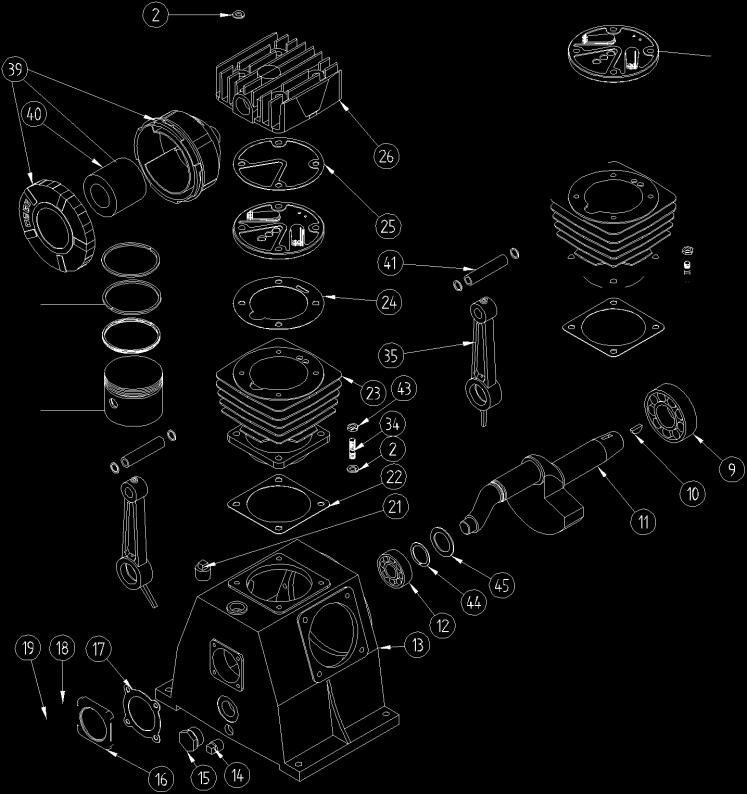

13 Section II Explode drawing 2

14 Section II Bill of material list Item LAP # Description Qty A Overhaul Kit:Include 1 of B,C,D B Ring Set:Include 1 of Item 38 C Valve Set:Include 1 of Item 42 D Gasket set:include 1 of Items 8,17,22,24, Hex Head Cap Screw- M8 X Lockwasher M Flat Washer Flywheel Flywheel 14.37" Single "AB" Groove Oil Seal Hex Head Cap Screw-M8 X Cap Drive end Gasket Drive End Ball Bearing Key 5 X Crankshaft Ball Bearing Crankcase Plug Drain 3/8" NPT Oil Sight Glass 1" NPT Cap - Rear End Gasket Rear End Lockwasher M Hex Head Cap Screw - M6 X Breather Oil Filler Plug - Cast Iron Gasket -Cylinder/Crankcase Cylinder Gasket - Cylinder/ Valve Deck Gasket - Valve Deck/ Cylinder Head Cylinder Head Iron Hex Head Cap Screw - M8 X Elbow Connector G 3/4" Finned Tube Airflow Nut G 3/4" T - Fitting - G 3/4" & 1-18 UNS Locknut UNS Ring UNS Connecting Size M8 X 22 Stud Threaded Both Ends Connecting Rod Snap Ring Piston - 80mm Ring Set Filter Filter Element Wrist pin Valve Deck Assembly Hex Head Nut-M Conn Rod Washer Stop Ring 30mm. Diam Breather Washer Inlet Valve Valve Deck Discharge Valve Valve Sstem Lockwasher Phillip Head Screw M4x
15 Section II Installation Instruction 1. Inspection Check for possible damage in transit and see that the pulley turns freely by hand Report any damage to delivering carrier at once. 2. Location Select a clean, dry and light location. In cold climates the compressor should be installed in a heated building Insulate cold water or other low temperature pipes that pass overhead to avoid the possible collection and dripping of condensate onto the compressor and motor which could cause rusting and or motor shorting Do not install the compressor in a boiler room, paint spray room or area where sandblasting is carried on. If air in the area where the compressor is to be installed is acid-laden, or dust laden the compressor intake should be piped to the outside This intake pipe should be increased one pipe size for every twenty (20) feet of run and the intake filters should be installed at the end of the pipes with a hood to protect them from the elements. If the compressor has to be located where the motor will be exposed to appreciable quantities of water, oil dirt, acid or alkaline fumes the motor must be of special construction to avoid rapid deterioration. Bolt the unit securely and evenly to a level base. Unless base is exactly level, shims will probably be required. Any space between base and foot should be shimmed rather than drawing foot down thus placing strain on unit. When the unit is properly shimmed vibration will be nominal. Allow sufficient space around compressor so that it is accessible from all sides for maintenance. Mount unit with pulley side toward the wall. but at least six (6) inches from it. 3. Starting A. If compressors are shipped without oil in the crankcase. Before starting. fill crankcase to the high level mark on the sight glass with LP Compressor compressor oil meeting the following specifications. AMBIENT OR ROOM TEMP. F VISCOSITY AT 100 F S.S.U. FLASH POINT F (Min.) POUR POINT F (Min.) CARBON RESIDUE /o (Max.) PREFERRED BASE 55 to to Naphthenic 32 to to * 5 10 Naphthenic 0 to to Naphthenic Above 120 or below 0 CONSULT FACTORY 4
16 Section II Operation manual Pump For operation in damp or humid locations, addition of rust inhibitor is recommended. B. Turn compressor over a few revolutions by hand to make sure that everything is free and in running condition. C. Check tension of the belts (See Paragraph 6). D. Remove tools, rags and any other objects from the vicinity of the compressor. E. Never put hands on the belts of idle units. unless main power is secured. F. Note direction of arrow on flywheel and be sure direction of rotation is correct when machine is started Correct direction is counter-clockwise when standing facing the flywheel. Air should be drawn through inter-cooler onto the cylinders for maximum cooling 5
17 Section II Operation manual Pump Operation Every compressor undergoes a trial run in the factory and is carefully tested and set. However, damage occurring afterwards, e.g. during transport, cannot be excluded. Therefore, the compressor should always be subjected to a trial run during commissioning and carefully monitored. WARNING Before start pump must be do the following job first!!! Check power supply and ; Check oil level; top up if necessary; Check fastener and piping connection For 3-phase power: Ensure no problem; start-up pump to check rolling direction, counter-clockwise is right, if not, please change 2 of 3-phase power wiring. If all items are ok, start the pump in operating. 6
18 Section III Parts Kits About parts kits of pump include 4 sets: 1. Overhaul Kit: Includes1 each of filer element and ring set, valve set, gasket set. 2. Ring Set: Includes 1 set of piston rings. 3. Valve Set: Includes 1 set of inlet valve and outlet valve. 4. Gasket Set: Includes1 each of gasket. For each pumps you can find the relevant parts kits number and describe in the explode drawings and bom list section. Safety information DANGER Please observe the following instructions when performing any maintenance, cleaning, repair work; when relocating the compressor plant; prior to installing and dismounting component parts, receivers, fittings and screw connections. Always isolate the compressor at the main switch prior to per forming any maintenance work. Secure the main switch against accidental switching on! Remove the electrical fuses in order to avoid accidents! Depressurize the compressor! Disconnect from the compressed air network by closing the ball valve on the compressed air outlet. Perform maintenance or servicing work. Only allow skilled and qualified welders to perform welding work on compressed air receivers! After welding work on compressed air receivers, new constructional and hydrostatic pressure tests are to be carried out. Prior to switching on again, check whether anyone else is working on the compressor! For your own safety, never omit a safety step! Otherwise you will risk injury from restarting, electric shock or parts which may fly off! 1
19 Section III Bolt torque chart Bolts Size Grade Torque(Ft.-Lb.) Position M6X End Cover Bolt M6X End Cover Bolt M6X Head to Cylinder Bolt M8X LP & HP Hold Down Bolt End Cover Bolt M8X Cylinder to Base Bolt M8X Connecting Rod Bolt M8X Head to Cylinder Bolt M8X Head to Cylinder Bolt M10X Cylinder to Base Bolt M10X Connecting Rod Bolt M12X Cylinder to Base Bolt M12X Head to Cylinder Bolt M12X Cylinder to Base Bolt M16X Flywheel Bolt Disassembling Pump Before dismantling a pump for overhauling it is advisable to obtain a set of valve parts, piston rings, and gaskets in addition to other required parts. A.Loosen motor, slide toward pump and remove belts. Drain oil from crankcase and if desired, remove complete pump from plat form. B. Remove flywheel bolt and remove pulley using a wedge or wheel puller if required. Remove key File edges of key way smooth to remove sharp edges which could cut oil seal during removal. C. Remove air inlet filter from head. D. Remove cylinder head from cylinder by removing cap screws. E. Before removing cylinder mark top of pistons nearest flywheel, so that they can be reinstalled in same position. Remove cylinder by removing bolts Cylinder can be removed easily by twisting slightly back and forth while pulling upward. Care should be taken that connecting rod and piston does not become damaged from striking metal when cylinder is removed The condition of cylinder, pistons, rings and bearing fits can then be checked. F. Remove end cover and slide crankshaft with connecting rods, pistons, etc. out 2

20 Section III of base being careful not to damage the oil feeder ring. Place pulley end of crankshaft in a vice using a soft jaws to prevent damage. G. To remove pistons. Remove roll pins, by driving them into the wrist pins, and push out wrist pins. Remove roll pins from wrist pins. H. When removing connecting rods see that rods and caps are kept in matched sets, noting the position with reference to the crankshaft of the identification marks on one side of each so that the connecting rod can be replaced in the same position it originally occupied. I. Drive oil seal out of base (only if replacement is necessary) with evenly spaced blows from inside. J. To dismantle head, remove low pressure hold-down covers and high pressure hold-down covers by removing cap screws. Lift out low pressure cages and high pressure cages. Low pressure valves and high pressure valves can be lifted out as well as the low pressure seat gasket (15. fig. 4) and high pressure seat gasket. K. To dismantle valves, place valve in a soft jaw vise and remove center screw Valves are now free to take apart Clean all parts thoroughly. Valve plates and seats- (must be smooth and flat and can sometimes be resurfaced by rubbing on fine emery cloth held on a smooth surface. Badly worn parts including springs, which lose tension after considerable use should be replaced. Fitting and Reassembling Clean all parts thoroughly before assembling. A. Crankshaft Base Be sure base is cleaned to remove all metal chips and dirt. Insert crankshaft and oil feeder ring only into base assemble end cover and tighten end cover bolts evenly. End cover gaskets or shims are furnished in three thicknesses and the proper combination must be selected so that crankshaft can be "spun" in the bearings without "end play". Also see that oil feeder ring turns freely within the guide lugs in the base. Then remove crankshaft. B. Piston Cylinder Check fit before assembling pistons to connecting rods. Pistons without rings should slide through the cylinder of their own weight and holding the skirt of the piston with the two thumbs there should be no appreciable side motion at any point of piston travel. Scored cylinders or pistons should be replaced. C. Wrist Pins should be "tap" fit by hammer. See that roll pin holes are in line. D. Wrist Pin Needle Bearing Fit so that piston can be "rocked" with three fingers the thumb on one side and index and middle fingers on the other. The piston should not rock of its own weight. Drive roll pin into wrist pin when piston and wrist pin holes are in line and piston is assembled to connecting rod. If replacement of a needle bearing ever becomes necessary, be sure to press in the new bearing so that the small hole through casting lines up with oil hole in rod. Wrist pin should also be replaced. 3
21 Section III E. Connecting Rod Crankshaft Tap cap, when insert bearings are assembled to rod and cap to make sure bearing is making contact and tighten rod bolts with lock washers in place to prevent loosening (torque 25 foot pounds). The combined piston and connecting rod should turn slowly on the crankshaft of their own weight if bearing adjustment incorrect. It will be noted that ends of the inserts extend slightly above the parting line of the rod and cap and under no circumstance should these ends of the inserts be filed. F. Reinstall crankshaft with pistons and connecting rods attached being careful not to damage oil feeder ring when fitting within base lugs and being sure there are no burrs or dirt on the pulley end of the crankshaft that might cut the oil seal. G. If oil seal is to be replaced slide over the crankshaft and press into place in the base, the lip or seal side toward the crankcase. Do not hammer directly on the seal. H. Replace valve parts in sequence indicated in explode drawing being careful not to force any parts together when tightening this center screw and locknut (Torque 28 foot pounds). After assembly.depress valve plate to insure that the valve works freely. I. Install key and pulley after cylinder head, intercooler and after-cooler are connected. J. Turn pulley over by hand several times to insure that no interference of any kind exists. K. "Running in" for a few hours without the head assembly is recommended if a pump has been completely overhauled especially if new pistons and/or cylinders have been installed. Valves Valves are generally considered to be maintenance items and require care by the user. They are the most important part of the compressor and the importance of proper care and maintenance cannot be over-emphasized. All valves should be removed from the cylinder head at the end of the first two or three months of operation and examined for cleanliness and carbon formation. Clean with safety solvent and blow off with compressed air. Depending on what is found at this inspection, the next inspection should not be more than 4 to 6 months later. These 2 inspections will guide you in scheduling periodic cleaning times which will pay off many times over in providing trouble free service and reduced down time. Troubleshooting 1. Slow Pumping Or Insufficient Pressure Can Be Caused By A Clogged inlet filter (Disassemble and clean thoroughly.) B Leaks in air lines, valves, fittings, etc. (Locate using soapy water if necessary: replace or tighten threaded parts.) C Compressor too small for equipment being operated (Check air requirements and add to compressor capacity consult dealer.) D Leaking head valves - (Remove hold-down covers and remove valves for examination. Repair or replace faulty valves.) Valves can be removed from head by tapping valve screw with hammer handle or piece of wood, to loosen valve from head, before lifting valve. Clean all parts thoroughly. Valves and seats must be flat and smooth and sometimes can be 4
22 Section III resurfaced by rubbing on fine emery cloth held on a smooth flat surface. Badly worn parts, including springs which lose tension after considerable use should be replaced Reassemble valve parts in sequence indicated in explode drawing. Examine valve gaskets carefully and replace if doubtful of condition. Be careful that nothing falls into the cylinder that could get caught between top of piston and cylinder head. Before reassembling valve look into cylinder through valve opening while turning flywheel by hand. 2. Excessive Oil Consumption "Oil Pumping" usually results from using the wrong type or an inferior grade of oil. Replacing worn or stuck piston rings will help correct this condition but contrary to popular belief, worn rings do not affect pumping efficiency appreciably. Piston rings can be replaced by removing cylinder while the heads are off. Remove rings clean grooves in piston. The low pressure oil ring provided is of the latest design and is the same as furnished on the new automobile engines. It is of three-piece construction with two chrome-plated rails and an expander ring. Some new units may pump a slight amount of oil for a period of time but as the chrome-plated rails seat to the cylinder walls this will gradually diminish. Should excessive oil consumption continue, the cylinders should be checked for scoring and the oil ring checked for proper assembly. The two ends of the expander rings are colored with paint for identification and when properly assembled should be butted, not overlapped. The high pressure oil ring is of the one piece construction. A coating of clean oil should be placed on the rings and the inside of the cylinders for ease of assembly and to minimize possibility of scoring cylinder. See Paragraph 16 for reassembly procedure. and 3. Noisy Operation Can Be Caused By A.Loose parts external (Tighten loose bolts, particularly the flywheel pulley to the crankshaft.) B. Foreign matter such as carbon, metal chips, etc. on pistons striking head at top of stroke (Remove head and clean). C. Piston extending above cylinder at top of stroke and hitting head. (Remove cylinder and add base gasket, not upper cylinder gasket.) D.End play in crankshaft (Remove end cover, take out one end cover gasket or shim and replace). Do not remove too many shims or binding may result, see Paragraph under fitting and reassembling. E. Loose valves Hex head cap screws are not tight enough. (Tighten screws ) Screws should be tightened snugly but not too tight as hold-down cover corners could be broken. Screws should be tightened evenly keeping covers parallel with cylinder head. Screws have nylon insert in threads and are of self-locking construction. They will not loosen from vibration and can be removed and retightened several times without losing their holding ability. 5
23 Section III F. Loose or worn parts Internal, e.g. pistons, connecting rods, wrist pins, valves (Pump should be overhauled preferably in distributors service department or factory. Loose rod bolts can be tightened after removing crankshaft, but if bearings are worn or scored, new insert bearings must be installed.) 4. Oil Leak At base or end cover gasket (Disassemble at point of leak, shellac or perma-gasket on both sides and reassemble. Maintain correct oil level). 5. Vibration Characteristic of all reciprocating machines can be held to a minimum by keeping the compressor securely fastened to a solid level foundation, maintaining proper belt alignment and keeping nuts and bolts tight. 6. Overheating Compression of air generates heat, much of which is dissipated as air passes over the cylinder Overheating can be caused by: A. Pump running backwards (Reverse direction.) Proper rotation is counterclockwise facing flywheel. B. One or more head valves failing to seat properly (Remove hold-down cover, valve cage, and valve. Clean, reseat or replace valves.) C. Blown cylinder head gasket (Replace after cleaning all traces of old gasket from head and cylinder.) D. Restriction in head, intercooler or check valve if used. (Remove and clean.) E. Lack of oil (Check oil level, if necessary, remove side plate to see that oil feeder ring is free to turn.) F. Dirt in cylinder fins - (Blow out with air.) G. Poor ventilation and high room temperature (If compressor cannot be moved, check possibility of piping intake to cooler location.) 7. Compressor Has No Or Insufficient Output A. Suction filter soiled-( Clean suction filter) B. Suction and pressure valves worn or defective-( Replace valves) C. Vent (unloading) valve does not close-( Check whether the vent (unloading) valve closes when the compressor is running; overhaul or replace valve, if necessary) 8. Safety Valve Of The First Stage Blows Off A. Suction and pressure valves of the second stage defective or worn-( Replace valves) B. Seal between valve and cylinder head defective-( Replace seal) 9. Oil Foam in The Crankcase A. Last stage piston worn-( Operate compressor with final stage valve head removed. If oil collects at rim of cylinder, piston clearance ok. If oil flows continuously out of cylinder, replace piston and liner) B. Last stage outlet valve defective-( Replace) 6
24 Section III 10. Oil out of from the breather Compressor piston jammed-(replace pistons and cylinders) Maintenance To obtain reliable and satisfactory service, this unit requires a consistent preventive maintenance program. Maintenance schedule pages are included in the back of this manual to aid in keeping the proper records. General 1. Check your compressor regularly! 2. Check entire system for air leakage around fittings, connections, and gaskets, using soap solution. 3. Remove dust or oil soiling. 4. Check fastener tightness by using torque wrench to the corresponding values within this guide. Safety information DANGER Please observe the following instructions when performing any maintenance, cleaning, repair work; when relocating the compressor plant; prior to installing and dismounting component parts, receivers, fittings and screw connections. Always isolate the compressor at the main switch prior to per forming any maintenance work. Secure the main switch against accidental switching on! Remove the electrical fuses in order to avoid accidents! Depressurize the compressor! Disconnect from the compressed air network by closing the ball valve on the compressed air outlet. Perform maintenance or servicing work. Only allow skilled and qualified welders to perform welding work on compressed air receivers! After welding work on compressed air receivers, new constructional and hydrostatic pressure tests are to be carried out. Prior to switching on again, check whether anyone else is working on the compressor! For your own safety, never omit a safety step! Otherwise you will risk injury from restarting, electric shock or parts which may fly off! 7

25 Section III Check oil level Check oil level every week and top up, if necessary: fill the oil tank with oil until the sight glass is 1/4 to 3/4 full. Oil sight glass WARNING Use the same brand oil Check and clean compressor valves if compressor fails to pump air or seems slow in filling up tank, disconnect unit from power source and remove valves and clean thoroughly, using compressed air and a soft wire brush. After cleaning exceptional care must be taken that all parts are replaced in exactly the same position and all joints must be tight or the compressor will not function properly. When all valves are replaced and connections tight, close hand valve at tank outlet for final test. Valve gaskets should be replaced each time valves are removed from pump. Replace springs, discs and seats when worn or damage. Valves must be reinstalled in original position. Incorrect valve replacement may result in overpressure of the cylinder head resulting in catastrophic failure, injury or death. Valve gaskets should be replaced each time valve are serviced. Checking the safety valve DANGER 8
26 Section III The safety valve must respond when the compressor pressure increases too high. The inter stage pressure relief valve is provided to protect against inter stage over pressure and is factory set for maximum pressure of 75 PSIG. If the pressure relief valve pops open, it indicates trouble. Shut down the unit immediately and determine and correct the malfunction. Inspect the head valves. Serious damage can result if not corrected and can lead to complete destruction of the unit. Tampering with the inter stage pressure relief valve, or plugging the opening destroys the protection provided and voids all warranty. The valve must be able to blow off the entire delivery quantity of the compressor. As it is rarely or never operated, it is of utmost importance for the safety of the compressor that the valve is regularly checked. Check the valve once a year or after 2000 operating hours. This is the only maintenance work which has to be performed while the compressor is running. Make sure that all safety devices are correctly installed! Never perform this work with the safety device removed! Danger of injury or death! WARNING Do not readjust!! Test safety valve on compressor: A ring is located at the free end of the safety valve. Pull the ring by hand. Never remove the lead seal at the head of the valve! If you now pull the ring further, the safety valve should blow off increasingly more air. If the valve blows off correctly, dropt hand tight in its seating and complete the check. If the valve does not blow off although you have pull the ring up to the end of the stud, it is defective. Please have a new safety valve fitted by LP COMPRESSOR Service. Test the valve as described in section "Testing safety valve on compressor". Compressor Oil General Compressors are factory filled with LP COMPRESSOR hydrocarbon based recip lubricant. This is an ISO non-detergent industrial lubricant with rust and oxidation inhibitors specially formulated for reciprocating compressors. It is recommended this compressor be maintained using this oil for ambient temperature above 32 F degreed. LP COMPRESSOR synthetic is a premium grade diester based synthetic lubricant providing excellent performance in high temperature applications. 9
27 Section III Do not mix oil types, weights or brands. Normal break-in period of LP COMPRESSOR air compressors is 25 hours. for the first 500 hours of compressor operation, a careful and regular check of the oil level should be made. Maintain oil level at the full time. Change To Synthetic Lubricant If changing to synthetic lubricant, the following steps must be completed. Compressor must run for a 25 hour break-in period using LP COMPRESSOR ISO 100 oil. Thoroughly drain existing oil from crankcase. Fill crankcase with a full charge of synthetic lubricant. Run compressor for 200 hours. Stop compressor and thoroughly drain the synthetic lubricant. Add a full charge of synthetic lubricant. Compressor now ready to run for extended period before next lubricant change made. Maintain oil level at the full line. Lubricant Frequency Of Oil Change Change oil every 3000 operating hours whichever comes first. For constant run applications in daily use or units subjected to extremely heavy use change oil monthly. Oil Recommendation Any Approved Oil Which Is Equal To Those Specified May Be Used Ambient Or Room Temperature 55 F To 120 F AMOCO SHELL MOBIL TEXACO CHEVRON GULF EXXON #51 Tellus Oil 41 Rotella Oil 30 Del vac 1230 Regal ER&O EP68X Paramount 58 Teresstic 100 DTE Heavy 10
28 Section III Ambient Or Room Temperature 32 F TO 55 F AMOCO SHELL MOBIL TEXACO CHEVRON GULF EXXON #31 Tellus Oil 33 Rotella Oil 20-20W Delvac 1220 DTE Heavy Med. Regal CR & O EP55X Paramount 49 Teresstic 68 Ambient Or Room Temperature 0 F TO 32 F AMOCO SHELL MOBIL TEXACO CHEVRON GULF EXXON #21 Tellus Oil 25 Rotella Oil 10W Delvac 1210 DTE Medium Cetus Oil EP45X Paramount 65 Teresstic 32 Suction Filter Regularly and carefully maintain the suction filter approx. every 500 operating hours, depending on the degree of soiling of the air taken in. Soiled suction filters can cause high oil consumption and reduced delivery quantity! If the installation site is heavily contaminated with dust, provide a dry air filter with paper cartridge. If the ambient air is heavily contaminated, we recommend using dry air filters. All compressors are available with a common air filter with under pressure display for all cylinders. Clean air filter Nearly 1500 operating hours or 1 year Check air filter and clean, if necessary After undoing the snap fasteners, lift the cover off and take out the filter cartridge. If the filter is soiled, clean as follows: Clean the cartridge on the outside by an inclined air blast at max. 3-5 bar. The cartridges can be cleaned up to three times before being replaced with new ones. Nearly 1500 operating hours or 1 year to change the filter element Clean the filter casing. Carefully inspect the cartridge for damage. Only use completely intact filters cartridges! Examine cover seal and replace with a new one if damaged. Insert filter cartridge, replace casing cover and close with fastening clamps. 11

29 Section III Maintenance intervals Cleaning the air filter We recommend servicing and maintaining your compressor at the following intervals. The hours of operation refer to average working conditions. Other intervals may apply depending on these conditions. Please contact LP COMPRESSOR in this event. Please record each maintenance task in the table on the last pages of these instructions! This may help LP COMPRESSOR -Service to locate faults if any occur. Maintenance work Maintenance intervals dependent on usage either after or Operating hours weekly / monthly yearly Check oil level and weekly top up, if necessary Check suction filter and clean, if necessary 500 monthly Replace suction filter 2000 X cartridge Check safety valve 2000 X Check cooler for 500 monthly soiling and clean, if necessary Change oil * every 1 years Check V-belt for X damage and replace, if necessary 12
30 Section III List of Maintenance and service work Date Operating Check / top Clean / check Replace air Check/replace Check safety Oil Check/clean hours up oil level air filter filter element V-belt valve change fin cooler 13
31 Section III Date Operating Check / top Clean / check Replace air Check/replace Check safety Oil Check/clean hours up oil level air filter filter element V-belt valve change fin cooler 14
32 Section III Date Operating Check / top Clean / check Replace air Check/replace Check safety Oil Check/clean hours up oil level air filter filter element V-belt valve change fin cooler 15
33 Section III Date Operating Check / top Clean / check Replace air Check/replace Check safety Oil Check/clean hours up oil level air filter filter element V-belt valve change fin cooler 16
34 Section III Date Operating Check / top Clean / check Replace air Check/replace Check safety Oil Check/clean hours up oil level air filter filter element V-belt valve change fin cooler 17
INSTRUCTION MANUAL: Industrial Series Piston Air Compressor. Model Number: V Part Number: L001128KNA
 INSTRUCTION MANUAL: Industrial Series Piston Air Compressor Model Number: V8051-335 Part Number: L001128KNA Pump Model: LP335 K335 Motor: 5 HP / 1 PH Air Tank: 80 Gal Vertical 1830 W. 15 th St. Houston,
Operating instructions
 Operating instructions Industrial piston air compressors Model: K332 Web Site: www.kelloggcompressor.com Issue: 06/2010 Contents Contents Pump service manual Page SECTION Ι... 1 INTRODUCTION... 1 UNPACKING
Operating instructions
 Operating instructions Industrial Piston Air Compressors Motor Driven Package C20215-7550 Pump Model: LPSS7550 Motor: 2 HP/1PH Air Tank: C20 7502 Mesa Road Houston, TX77028 Telephone: (713) 635-6331 E-mail:
Operating instructions
 Operating instructions Industrial piston air compressors Model: K352 Web Site: www.kelloggcompressor.com Issue: 06/2010 Contents Contents Pump service manual Page SECTION Ι... 1 INTRODUCTION... 1 UNPACKING
Operating instructions
 Operating instructions Industrial Piston Air Compressors Motor Driven Package W8GY5-7550 Pump Model: LPSS7550 Engine: 5 HP Air Tank: 8 7502 Mesa Road Houston, TX77028 Telephone: (713) 635-6331 E-mail:
Operating instructions
 Operating instructions Industrial piston air compressors Model: LP462 7502 Mesa Road Houston, TX77028 Telephone: (713) 635-6331 E-mail: service@lapante.com Web Site: www.laplantecompressor.com Issue: 06/2010
Operating instructions
 Operating instructions Industrial piston air compressors Model: LP462 7502 Mesa Road Houston, TX77028 Telephone: (713) 635-6331 E-mail: service@lapante.com Web Site: www.kelloggcompressor.com Issue: 06/2010
Operating instructions
 Operating instructions Industrial piston air compressors Model: K452 Web Site: www.kellogg-american.com Issue: 06/2010 Contents Contents Pump service manual Page SECTION Ι...1 INTRODUCTION... 1 UNPACKING
AIR COMPRESSOR OPERATING INSTRUCTION AND PARTS LIST
 AIR COMPRESSOR OPERATING INSTRUCTION AND PARTS LIST BELT TYPE IMPORTANT PLEASE MAKE CERTAIN THAT THE PERSON WHO IS TO USE THIS EQUIPMENT CAREFULLY READS AND UNDERSTANDS THESE INSTRUCTIONS BEFORE STARTING
Portable Electric/Gas Compressor Operating Instructions
 Portable Electric/Gas Compressor Operating Instructions NOTICE Carefully read this instruction manual before attempting to operate this compressor. MODEL # SERIAL # 1-800-551-2406 TABLE OF CONTENTS Safety
SERIES PC INSTRUCTION AND OPERATION MANUAL
 MEGGA SERIES PC INSTRUCTION AND OPERATION MANUAL Models PCT and PCF Close-coupled and frame-mounted single-stage horizontal end-suction pumps. WARNING: Read this manual before installing or operating this
DISCLAIMER: SPECIFICATIONS:
 5HP 80 GALLON TWO STAGE COMPRESSOR Models: 7654 CALIFORNIA PROPOSITION 65 WARNING: You can create dust when you cut, sand, drill or grind materials such as wood, paint, metal, concrete, cement, or other
I & M Mark 78 Series. Ideal Installation. Start-Up. Installation & Maintenance Instructions for Mark 78 Control Valves (1-1/2-2 )
") I & M Mark 8 Series 0 Wasson Road Cincinnati, OH 4509 USA Phone 5-5-5600 Fax 5-8-005 info@richardsind.com www.jordanvalve.com Installation & Maintenance Instructions for Mark 8 Control Valves (-/ - ) Warning:
I & M Mark 8 Series 0 Wasson Road Cincinnati, OH 4509 USA Phone 5-5-5600 Fax 5-8-005 info@richardsind.com www.jordanvalve.com Installation & Maintenance Instructions for Mark 8 Control Valves (-/ - ) Warning:
I & M Mark 78 Series. Ideal Installation. Start-Up. Installation & Maintenance Instructions for Mark 78 Control Valves (1/2-1 )
") I & M Mark 8 Series 30 Wasson Road Cincinnati, OH 4509 USA Phone 53-533-5600 Fax 53-8-005 info@richardsind.com www.jordanvalve.com Installation & Maintenance Instructions for Mark 8 Control Valves (/ -
I & M Mark 8 Series 30 Wasson Road Cincinnati, OH 4509 USA Phone 53-533-5600 Fax 53-8-005 info@richardsind.com www.jordanvalve.com Installation & Maintenance Instructions for Mark 8 Control Valves (/ -
Standard Valves Series Globe Valves Series Angle Valves Series Way-Valves
 Installation, Operation, Maintenance Instructions Standard Valves Series 035 000 Globe Valves Series 031 000 Angle Valves Series 033 000 3-Way-Valves 1 GENERAL INFORMATION These instructions are designed
SPECIFICATIONS: Tank Size: 80 gallons PUMP RPMs: 1050 CFM: 40PSI; 90 PSI Max Pressure: 150 PSI Thermal overload protection
 5HP 80 GALLON TWO STAGE COMPRESSOR Models: 51866, 51870 CALIFORNIA PROPOSITION 65 WARNING: You can create dust when you cut, sand, drill or grind materials such as wood, paint, metal, concrete, cement,
S3 General Installation
 Wilfley Drylock Assembly General Installation Operating & General Servicing Clearance Settings Safety Precautions Spare Parts Ordering Assembly Instructions Model S3 General Installation Inspection upon
Maintenance and Repair
 Maintenance and Repair WARNING ALWAYS shut off the engine, remove key from ignition, make sure the engine is cool, and disconnect the spark plug and positive battery terminal from the battery before cleaning,
Air Compressor. Operating & Maintenance Instructions 1110 ENGINE DRIVEN - 1 -
 Air Compressor ENGINE DRIVEN Operating & Maintenance Instructions 1110-1 - Read these safety instructions before using the equipment. INTRODUCTION Thank you for purchasing this Clarke portable compressor.
Routine Compressor Maintenance
 Establishing a regular, well-organized maintenance program and strictly following it is critical to maintaining the performance of a compressed air system. One person should be given the responsibility
TWO-STAGE HYDRAULIC PUMP. RWP55-IBT-Air
 ORIGINAL INSTRUCTIONS Form No.1000458 5 SPX Corporation 5885 11th Street Rockford, IL 61109-3699 USA Tech. Services: (800) 477-8326 Fax: (800) 765-8326 Order Entry: (800) 541-1418 Fax: (800) 288-7031 Internet
TECHNICAL SERVICE MANUAL
 Electronic copies of the most current TSM issue can be found on the Viking Pump website at www.vikingpump.com TECHNICAL SERVICE MANUAL industrial heavy duty motor speed pumps SERIES 4076 AND 4176 SIZES
Split Body Valves with Bellows Seal Series Globe Valves Series Angle Valves Series Way-Valves
 Installation, Operation, Maintenance Instructions Split Body Valves with Bellows Seal Series 025 300 Globe Valves Series 027 300 Angle Valves Series 028 300 3-Way-Valves 1 GENERAL INFORMATION These instructions
Model BP6150. Triplex Ceramic Plunger Pump Operating Instructions/ Manual
 Model BP6150 Triplex Ceramic Plunger Pump Operating Instructions/ Manual Contents: Installation Instructions: page 2 Pump Specs: page 3 Exploded View: page 4 Parts List / Kits Torque Specifications: page
Portable Oil Free Silent Series Compressor Operating Instructions
 Portable Oil Free Silent Series Compressor Operating Instructions NOTICE Carefully read this instruction manual before attempting to operate this compressor. MODEL # SERIAL # 1-800-551-2406 www.eaglecompressor.com
CONTENTS. VIKING PUMP, INC. A Unit of IDEX Corporation Cedar Falls, IA USA SECTION TSM 710.1
 TECHNICAL SERVICE MANUAL industrial heavy duty motor speed pumps SERIES 4076 AND 4176 SIZES hle, ate and ale SECTION TSM 710.1 PAGE 1 of 8 ISSUE B CONTENTS Introduction....................... 1 Safety
Table 6-1. Problems and solutions with pump operations. No Fluid Delivery
 Table 6-1. and solutions with pump operations No Fluid Delivery Fluid level in the reservoir is low. Oil intake pipe or inlet filter is plugged. Air leak in the inlet line prevents priming or causes noise
SERVICE INSTRUCTIONS. Transfer Pump
 TM TM SERVICE INSTRUCTIONS Transfer Pump 6799 DESCRIPTION Model 6799 is an air operated, self-priming, piston type transfer pump designed to transfer gasoline or diesel fuel at 30 gpm or oils up to SAE
MAINTENANCE MANUAL FOR THERMOSTATIC TEMPERATURE REGULATING VALVE TRAC STYLE P
 MANUAL NUMBER P-EFS-1 MAINTENANCE MANUAL FOR THERMOSTATIC TEMPERATURE REGULATING VALVE TRAC STYLE P TRAC Regulator Company Inc. 160 South Terrace Avenue Mount Vernon, New York USA 10550-2408 Phone: (914)
INSTRUCTION MANUAL INTERNAL GEAR PUMP TITAN G-4124A SERIES=> FLANGED TITAN G-124A SERIES => FLANGED MODELS:
 INSTRUCTION MANUAL INTERNAL GEAR PUMP TITAN G-4124A SERIES=> FLANGED TITAN G-124A SERIES => FLANGED MODELS: G-H, G-HL, G-K, G-KK, G-L, G-LQ, G-LL, GLS, G-Q, G-QS 1 Contents Maintenance Thrust bearing adjustment
AIR COMPRESSOR INSTALLATION AND START-UP MANUAL. Table of Contents. Page# 1. INTRODUCTION 2. OWNER'S OBLIGATIONS 3. INSTALLATION AND START UP
 AIR COMPRESSOR INSTALLATION AND START-UP MANUAL Table of Contents Page# 1. INTRODUCTION 2. OWNER'S OBLIGATIONS 3. INSTALLATION AND START UP 4. INSTALLATION AND START UP / GAS 5. TROUBLE-SHOOTING GUIDE
Operating instructions Form no safety definitions
 Operating instructions Form no. 1000437 safety definitions safety symbols are used to identify any action or lack of action that can cause personal injury. Your reading and understanding of these safety
SIP Direct Drive Oil-Lube Air Compressors - Operating & Maintenance Instructions
 SIP Direct Drive Oil-Lube Air Compressors - Operating & Maintenance Instructions Please read and fully understand the instructions in this manual before operation. Keep this manual safe for future reference.
Iron Horse Air Compressor part breakdown - IHD6160V1 Item Description IHD6160V1 IHD6160V1 Call for the Customer Service Department.
 Iron Horse Air Compressor part breakdown - IHD6160V1 Item Description IHD6160V1 1 Compressor w/ Flywheel CC2065 2 Discharge Tube w/ Fittings TU-23-AL 3 Pressure Gauge PG200-2.5R 4 Air Receiver 60V20X48SPL
Pump Operating and Maintenance Manual - Models
 Pump Operating and Maintenance Manual - Models 78-00111 - 78-0057 Thank you for purchasing the SDI Diaphragm Pump manufactured by Comet Pump. Comet produces quality products which are safe, efficient and
6L Oil-less Air Compressor 53103
 6L Oil-less Air Compressor 53103 Operating Instructions Please read and save these instructions before attempting to assemble, install, operate or maintain the product. Protect yourself and others by observing
Maintenance Instructions
 General Note These instructions contain information common to more than one model of Bevel Gear Drive. To simplify reading, similar models have been grouped as follows: GROUP 1 Models 11, 0, 1,, (illustrated),,
INSTRUCTION AND REPAIR MANUAL MODELS 341A, 342A AND 344A 6
 SECTION 6 ITEM 0 DATED JUNE 1998 SUPERSEDES ITEMS 1, 2, DATED MARCH 1992 INSTRUCTION AND REPAIR MANUAL MODELS 1A, 2A AND A 6 NOTE This repair manual is applicable to pump Models 1A, 2A and A. All photos
IMPORTANT OPERATING CONDITIONS. Failure to comply with any of these conditions invalidates the warranty. STANDARD CONFIGURATIONS
 X-SERIES TRIPLEX CERAMIC PLUNGER PUMPS OPERATING MANUAL MODELS X8 X10 X20 IMPORTANT OPERATING CONDITIONS Failure to comply with any of these conditions invalidates the warranty. Lubrication - Prior to
Series Base mounted pump. Installation and operating instructions
 Series 4030 Installation and File No: 40.80 Date: june 25, 2015 Supersedes: 40.80 Date: october 10, 2009 contents General 4 Inspection 4 Installation - Series 4030 base mounted Pump 4 1.0 Location 4 2.0
Air Trap TATSU2. Copyright 2013 by TLV CO., LTD. All rights reserved ISO 9001/ ISO M-02 (TATSU2) 7 August 2013.
 7 August 2013.") 172-65177M-02 (TATSU2) 7 August 2013 ISO 9001/ ISO 14001 Manufacturer Kakogawa, Japan is approved by LRQA LTD. to ISO 9001/14001 Air Trap TATSU2 Copyright 2013 by TLV CO., LTD. All rights reserved 1 Contents
172-65177M-02 (TATSU2) 7 August 2013 ISO 9001/ ISO 14001 Manufacturer Kakogawa, Japan is approved by LRQA LTD. to ISO 9001/14001 Air Trap TATSU2 Copyright 2013 by TLV CO., LTD. All rights reserved 1 Contents
INSTALLATION, OPERATING AND MAINTENANCE INSTRUCTIONS D SERIES TABLE OF CONTENTS
 INSTALLATION, OPERATING AND MAINTENANCE INSTRUCTIONS D SERIES GENERAL INFORMATION TERMS CONCERNING SAFETY UNPACKING INSTALLATIONS VALVE MAINTENANCE TABLE OF CONTENTS VALVE DISASSEMBLY AND REASSEMBLY PLUG
Service Manual. Climate Control Inc.
 SECTION 2 Service - Clutch Servicing (Removal & Installation) - Shaft Seal Servicing (Removal & Installation) - Head & Valve Plate Servicing (Removal & Installation) - Baseplate Servicing (Removal & Installation)
TECHNICAL SERVICE MANUAL
 TECHNICAL SERVICE MANUAL HEAVY-DUTY bracket mounted PUMPS SERIES 4193 AND 493 SIZES GG - AL SECTION TSM 154 PAGE 1 of 10 ISSUE C CONTENTS Introduction....................... 1 Special Information...................
SERVICE PARTS LIST SPECIFY CATALOG NO. AND SERIAL NO. WHEN ORDERING PARTS 13 HP DIRECT DRIVE PRESSURE WASHER CATALOG NO
 SPECIFY CATALOG NO. AND SERIAL NO. WHEN ORDERING PARTS HP DIRECT DRIVE PRESSURE WASHER CATALOG NO. 555-22 SERVICE PARTS LIST STARTING SERIAL NUMBER B06A REVISED BULLETIN PAGE OF BULLETIN NO. 5-20-000 DATE
Ideal Installation. I & M Mark 67 (1/2 6 ) Control Line. Installation & Maintenance Instructions for Mark 67 Pressure Regulators
 Control Line. Installation & Maintenance Instructions for Mark 67 Pressure Regulators") I & M Mark (/ ) 0 Wasson Road Cincinnati, OH 0 USA Phone --00 Fax -8-00 info@richardsind.com www.jordanvalve.com Installation & Maintenance Instructions for Mark Pressure Regulators Warning: Jordan Valve
I & M Mark (/ ) 0 Wasson Road Cincinnati, OH 0 USA Phone --00 Fax -8-00 info@richardsind.com www.jordanvalve.com Installation & Maintenance Instructions for Mark Pressure Regulators Warning: Jordan Valve
PARTS LIST FOR AIR COMPRESSORS AC-SH20-2 AC-SV20-2 ENGINE OIL GRADE: HONDA: SAE 10W-30. Below 40 F=SAE 10W-30 ENGINE OIL CAPACITY:
 PARTS LIST FOR AIR COMPRESSORS AC-SH20-2 AC-SV20-2 ENGINE OIL GRADE: HONDA: SAE 10W-30 VANGUARD: Above 40 F=SAE30 Below 40 F=SAE 10W-30 ENGINE OIL CAPACITY: HONDA: 37 oz. VANGUARD: 40 oz. MAXIMUM PRESSURE
MARLEY ENGINEERED PRODUCTS OPERATING INSTRUCTIONS AND PARTS LIST
 MARLEY ENGINEERED PRODUCTS OPERATING INSTRUCTIONS AND PARTS LIST TUBE AXIAL DUCT FANS INDUSTRIAL PROPELLER FANS INDUSTRIAL ROOF EXHAUSTERS HEAVY DUTY MAN/PRODUCT COOLERS WARNING BY ACCEPTANCE OF THIS MERCHANDISE,
Pump Owner s Manual. PLEASE! Read All Instructions Carefully Before Installing Pump
 Pump Owner s Manual PLEASE! Read All Instructions Carefully Before Installing Pump Guarantee Associate Engineering Corporation warrants that pumps purchased from them will be free of defects in material
I & M 8000 Series. Ideal Installation Schematic. Preferred Installation. Trouble Shooting
 I & M 8000 Series 3170 Wasson Road Cincinnati, OH 45209 USA Phone 513-533-5600 Fax 513-871-0105 lowflow@richardsind.com www.lowflowvalve.com Installation & Maintenance Instructions for 8000 Series Low
 VOLUME 3.2 2 This page intentionally left blank JTC 760 Operator s Manual PAGE 3 Table of Contents 1 Summary 1.1 Technical Data 4 1.2 Range of Application 4 1.3 Intended Use 5 1.4 Safety Precaution 5 2
6 Litre Oil-Less Air Compressor
 Operator s Manual 6 Litre Oil-Less Air Compressor WARNING! Before using this appliance, read the Operator s manual and follow all its safety rules and instructions. SPECIFICATION HWKAC1 1.1 kw / 1.5 HP
Operating & Maintenance Manual For Steam Conditioning Valve
 For Steam Conditioning Valve 1 Table of Contents 1.0 Introduction 3 2.0 Product description 3 3.0 Safety Instruction 4 4.0 Installation and Commissioning 5 5.0 Valve Disassembly 6 6.0 Maintenance 6 7.0
TECHNICAL SERVICE MANUAL
 Electronic copies of the most current TSM issue can be found on the Viking Pump website at www.vikingcom TECHNICAL SERVICE MANUAL abrasive liquid pumps SERIES 4625 SIZES f - fh SECTION TSM 410.1 PAGE 1
PRODUCT OBSOLETED 4Q16
 Electronic copies of the most current TSM issue can be found on the Viking Pump website at www.vikingcom TECHNICAL SERVICE MANUAL abrasive liquid pumps SERIES 4625 SIZES f - fh SECTION TSM 410.1 PAGE 1
SPLASH LUBRICATED AIR COMPRESSOR PUMPS
 Operating Instructions SPLASH LUBRICATED AIR COMPRESSOR PUMPS Airbase Industries designs and manufactures products for safe operation. However, operators and maintenance persons are responsibile for maintaining
P SERIES PUMPS. 18mm Versions Nickle-Aluminum Bronze Models: P , P , P , P , P , P , P
 P200-3100 SERIES PUMPS 18mm Versions Nickle-Aluminum Bronze Models: P217-3100, P218-3100, P219-3100, P220-3100, P221-3100, P227-3100, P230-3100 Triplex Ceramic Plunger Pump Operating Instructions/ Repair
Model Ton Hand Carry Axle Jack P/N: CJ67D0250-1
 Model 1504-50 15 Ton Hand Carry Axle Jack P/N: CJ67D0250-1 Operation and Maintenance Manual with Illustrated Parts List 2222 South Third Street Columbus, Ohio 43207-2402 Phone (614) 443-7492 FAX (614)
Injector. General Information CAUTION. Use only the specified injector for the engine.
 Page 1 of 32 006-026 Injector General Information CAUTION Use only the specified injector for the engine. All engines use closed nozzle, hole-type injectors. However, the injectors can have different part
Jet Fans. Instruction Manual READ AND SAVE THESE INSTRUCTIONS WARRANTY
 Jet Fans Instruction Manual READ AND SAVE THESE INSTRUCTIONS WARRANTY All Leader Fan products are guaranteed to be free from defects of workmanship or material and to function satisfactorily when properly
HD372A DISASSEMBLY SLIDES
 COMPRESSORS 03/93 CB-128 HD372A DISASSEMBLY SLIDES Each slide has a descriptive paragraph. Each paragraph has the main points outlined so reading the full text word for word is not necessary when presenting
MOREHOUSE INSTRUMENT COMPANY, INC. 60,000 LBS CAPACITY AIRCRAFT PART NUMBER SCALE S FORCE CALIBRATION PRESS PART NO.
 INDEX 1. GENERAL SPECIFICATION AND DRAWING 804000-03... 2 2. ASSEMBLY INSTRUCTIONS... 5 3. OPERATING INSTRUCTIONS... 6 4. MAINTENANCE INSTRUCTIONS... 7 5. CERTIFICATE OF CAPACITY LOAD TEST AND OVERLOAD...
Maintenance Information
 51984144 Edition 6 May 2014 Air Paving Breaker MX60 & MX90 Maintenance Information Save These Instructions Product Safety Information WARNING Failure to observe the following warnings, and to avoid these
3" & 4" Cast Iron Self-Priming Centrifugal Pump Instruction Manual
 12 3" & 4" Cast Iron Self-Priming Centrifugal Pump Instruction Manual 333 & 444 Series Read these instructions and the instructions covering operation of the pump drive unit. Do not operate the gas engine
At CHINOOK we have two key words: specialisation and experience. Air compressors are own only product. All our engineering skills and nearly thirty
 R01 21/09/2005 At CHINOOK we have two key words: specialisation and experience. Air compressors are own only product. All our engineering skills and nearly thirty years of manufacturing experience and
NOTE: Visit our website at for video repair procedures, under the Tools section.
 Repair Instructions Hypro Repair Tools: Tool Box No. 3010-0168 1/4" Allen Wrench No. 3020-0008 Support Bars (2) No. 3010-0064 Port Brush No. 3010-0066 1/16" Allen Wrench No. 3020-0009 Brush Holder No.
MetroPrime 22MPC Self-Priming Centrifugal Pump
 Page 1 of 6 prevent priming or reduce pump capacity. OPERATION The 22 MPC-Metropolitan Pump is a self-priming centrifugal pump and only requires priming prior to its initial start. The pump will retain
APCO CRF-100A RUBBER FLAPPER SWING CHECK VALVES
 APCO CRF-100A RUBBER FLAPPER SWING CHECK VALVES Instruction D12043 June 2016 DeZURIK Instructions These instructions provide installation, operation and maintenance information for APCO CRF-100A Rubber
AIR COMPRESSOR AC5161B AC5161BP. User Manual
 AIR COMPRESSOR AC5161B AC5161BP User Manual table of contents table of contents Safety 6 Safety Rules 7 Safety Warnings Overview 11 Basic Air Compressor Components Assembly 13 Assembling the Compressor
4 - Way Control 4 - Way Control 4 - Way Control with lock
 INSTALLATION / OPERATION / MAINTENANCE 1. DESCRIPTION MODEL 0-02 (Full Internal Port) Powertrol Valve This manual contains information for installation, operation and maintenance of the Cla-Val Co. 0-02
PACKING, HANDLING, TRANSPORTING AND STORING MOTORS
 PACKING, HANDLING, TRANSPORTING AND STORING MOTORS Make sure that the shaft of the motor is not loaded in any way and is protected from knocks. Axial loads or shocks may easily damage the bearings inside
Hydraulic Hand Pallet Trucks
 Operating Instructions & Parts Manual 12U124 Please read and save these instructions. Read carefully before attempting to assemble, install, operate, or maintain the product described. Protect yourself
SELF PRIMING CHEMICAL SERVICE PUMPS
 SELF PRIMING CHEMICAL SERVICE PUMPS INSTALLATION AND OPERATING INSTRUCTIONS This Manual covers: SELF PRIMING MODEL RANGE J50ECX TO J250ECX STAINLESS STEEL*, and NON METALLIC SEAL PUMP MODEL: SERIAL NO:
TECHNICAL SERVICE MANUAL
 Electronic copies of the most current TSM issue can be found on the Viking Pump website at www.vikingpump.com TECHNICAL SERVICE MANUAL VIKING HELICAL GEAR REDUCERS A, B, AND C SIZES SECTION PAGE ISSUE
Maintenance Information
 16573370 Edition 2 February 2014 Air Grinder 99V Series Maintenance Information Save These Instructions Product Safety Information WARNING Failure to observe the following warnings, and to avoid these
INSTALLATION, OPERATION AND MAINTENANCE INSTRUCTIONS
 INSTALLATION, OPERATION AND MAINTENANCE INSTRUCTIONS Contents Section 1. General Observations... 2 2. Operation... 4 3. Control During Operation... 5 4. Trouble Shooting... 6 5. Maintenance... 7 Please
Water pump Owner's Manual
 Water pump Owner's Manual Safety Precautions I. General Safeguards Please read this operation manual to have a thorough understanding of the content there before use the product. Failure to do so may lead
Valtek Spring Cylinder Linear Actuators
 Valtek Linear Actuators GENERAL INFORMATION The following instructions are designed to assist in installing, troubleshooting and servicing Valtek spring cylinder actuators. Product users and maintenance
TECHNICAL SERVICE MANUAL
 Electronic copies of the most current TSM issue can be found on the Viking Pump website at www.vikingpump.com TECHNICAL SERVICE MANUAL SECTION TSM 610 Viking Helical Gear Reducers a, b, and c sizes PAGE
INSTALLATION, OPERATION AND MAINTENANCE MANUAL WALL EXHAUST FANS BELT & DIRECT DRIVE XB, HV, HVA, ADD, DDS, DDP
 INSTALLATION, OPERATION AND MAINTENANCE MANUAL WALL EXHAUST FANS BELT & DIRECT DRIVE XB, HV, HVA, ADD, DDS, DDP The purpose of this manual is to aid in the proper installation and operation of the fans.
BA440 PISTON. Hydraulic Air Compressor
 P M BA440 PISTON Hydraulic Air Compressor This manual must be read carefully before using your Boss Industries, LLC BA440 PISTON. Store in a safe and convenient location for future reference. http://www.bossair.com
DeZURIK 2 20" BOS BUTTERFLY VALVES
 2 20" BOS BUTTERFLY VALVES Instruction D10459 October 2013 2-20 BOS Butterfly Valves Instructions These instructions provide information about BOS Butterfly Valves. They are for use by personnel who are
PARTS MANUAL FOR TWO STAGE AIR COMPRESSOR
 PARTS MANUAL FOR TWO STAGE AIR COMPRESSOR SPECIFICATION CHART Model No. Horsepower Voltage-Single Phase Minimum Branch Circuit Requirement *Fuse Type Air Tank Capacity Approximate Cut-in Pressure Approximate
Installation, Operation, and Maintenance Manual
 Installation, Operation, and Maintenance Manual API 6D Piston Check Valve - IOM: Installation, Operation and Maintenance Manual 1/16 Table of Contents 1 INTRODUCTION... 3 1.1 SCOPE... 3 1.2 DISCLAIMER...
Electric Compressors US7580V B6000 FS002 MM36H675 SV25200 PS10M FIB02DC CV22 DT023 BG31184 BA67(2) S2AK61H
 S2AK61H") Electric Compressors 10 09 01 02 03 08 04 05 06 07 Illustration Part Description Number US660V US580V 1 Compressor B3800 T29S 2 Air Filter 2281000 4981000 3 Electric Motor M182711 M182703 4 Safety Valve
Electric Compressors 10 09 01 02 03 08 04 05 06 07 Illustration Part Description Number US660V US580V 1 Compressor B3800 T29S 2 Air Filter 2281000 4981000 3 Electric Motor M182711 M182703 4 Safety Valve
C T h e A d va n t a g e
 C The Advantage TABLE OF CONTENTS Introduction...1 Product Numbering System...1 Safety...2 Receiving and Inspection...2 Installation...2 Electrical...3 Parts Identification...7 Lubrication...9 Start-up...10
Crispin Valves Operating Guide. Crispin
 Crispin Valves Operating Guide Crispin Since 1905 Crispin Multiplex Manufacturing Co. 600 Fowler Avenue Berwick, PA 18603 1-800-AIR-VALV T: (570) 752-4524 F: (570) 752-4962 www.crispinvalve.com sales@crispinvalve.com
PR Series Positive Rotary Pumps
 PRSM PR Series Positive Rotary Pumps Models PR, PRE, and PRED CONTENTS Thank you for purchasing a Tri-Clover Product! This manual contains disassembly and assembly instructions, maintenance procedures,
Butterfly Valve Type 57P
 Butterfly Valve Type 57P Contents Lever Type: 50-200 mm (2-8 ) Body Material: CPVC Gear Type: 50-200mm (2-8 ) Body Material: CPVC (1) Be sure to read the following warranty clauses of our product 1 (2)
Operating and Maintenance Manual Gas & Diesel Engine Powered Self-Priming Trash Pumps Series
 Operating and Maintenance Manual Gas & Diesel Engine Powered Self-Priming Trash Pumps 3200 Series Operating Manual Contents: Model Number/Serial Number/Safety Information Pg. 1 Safety Information (Con
DeZURIK R1 POWERRAC ACTUATOR ON 1/2-3" PEC ECCENTRIC VALVES
 R1 POWERRAC ACTUATOR ON 1/2-3" PEC ECCENTRIC VALVES Instruction D10381 August 2012 Instructions These instructions provide information about the R1 PowerRac actuator. They are for use by personnel who
COLT 2310, 2510, AND 2712 COM PACT TRACTORS CHAPTER 9 TROUBLESHOOTING AND ANALYSIS
 COLT 2310, 2510, AND 2712 COM PACT TRACTORS CHAPTER 9 TROUBLESHOOTING AND ANALYSIS 9-A-1 UPON RECEIVING ANENGINE FORRE- PAIR. Learn the history of the unit from the customer. While the customer is present
Float Dynamic Steam Trap J10
 172-65237MA-01 (J10) 12 June 2015 ISO 9001/ ISO 14001 Manufacturer Kakogawa, Japan is approved by LRQA LTD. to ISO 9001/14001 Float Dynamic Steam Trap J10 Copyright 2015 by TLV CO., LTD. All rights reserved
MICHIGAN FLUID POWER
 MICHIGAN FLUID POWER Air Driven Hydraulic Pumps, Power Units and Intensifiers P901 Installation, Use and Maintenance Manual Contents Introduction, Guarantee and Identification Plate Description, Start
Models GP5132, GP5136, GP5142 & GP5145. Triplex Ceramic Plunger Pump Operating Instructions / Manual
 Models GP5132, GP5136, GP5142 & GP5145 Triplex Ceramic Plunger Pump Operating Instructions / Manual Updated 07/14 Contents: Installation Instructions: page 2 Pump Specifications: page 3 Exploded View:
SAI GM Series Piston Hydraulic Motor Crankshaft Design Radial Piston Motors
 SAI GM Series Piston Hydraulic Motor Crankshaft Design Radial Piston Motors www.chinawinches.cn (Dimension: inch) Brief Performance Table of Sai GM Series Piston Hydraulic Motor (Full range GM05- GM9 series)
Installation Instructions
 Preparing your vehicle to install your brake system upgrade 1. Rack the vehicle. 2. If you don t have a rack, then you must take extra safety precautions. 3. Choose a firmly packed and level ground to
Model GP Triplex Ceramic Plunger Pump Operating Instructions/ Manual
 Model GP6145-3100 Triplex Ceramic Plunger Pump Operating Instructions/ Manual Contents: Installation Instructions: page 2 Pump Specifications: page 3 Exploded View: page 4 Parts List / Kits: page 5 Repair
HYDRAULIC SPREADER. Max. Pressure: 10,000 PSI (700 BAR) Unit Weight: HS2000 = 4.8 LBS. (2.17 Kg) HS3000 = 22 LBS. (9.98 Kg)
 Unit Weight: HS2000 = 4.8 LBS. (2.17 Kg) HS3000 = 22 LBS. (9.98 Kg)") Form No. 103525 Operating Instructions for: HS2000 HS3000 HYDRAULIC SPREADER Max. Pressure: 10,000 PSI (700 BAR) Unit Weight: HS2000 = 4.8 LBS. (2.17 Kg) HS3000 = 22 LBS. (9.98 Kg) Definition: Hydraulic
Form No. 103525 Operating Instructions for: HS2000 HS3000 HYDRAULIC SPREADER Max. Pressure: 10,000 PSI (700 BAR) Unit Weight: HS2000 = 4.8 LBS. (2.17 Kg) HS3000 = 22 LBS. (9.98 Kg) Definition: Hydraulic
SAFETY AND OPERATING MANUAL
 SAFETY AND OPERATING MANUAL COLD WATER PETROL WATER BLASTERS Read Safety & Operating Instructions Before Commencing Operation THESE INSTRUCTIONS MUST BE READ AND ADHERED TO BEFORE OPERATING THIS MACHINE.