Air Compressor. Operating & Maintenance Instructions 1110 ENGINE DRIVEN - 1 -
|
|
|
- Holly Carson
- 6 years ago
- Views:
Transcription


1 Air Compressor ENGINE DRIVEN Operating & Maintenance Instructions
2 Read these safety instructions before using the equipment. INTRODUCTION Thank you for purchasing this Clarke portable compressor. The unit is powered by a Honda engine, a manual for which, is provided separately. Please refer to that manual for all matters relating to the engine,...starting and stopping procedures, maintenance etc. GUARANTEE This product is guaranteed against faults in manufacture for 12 months from purchase date. Please keep your receipt as proof of purchase. This guarantee is invalid if the product has been abused or tampered with in any way, or not used for the purpose for which it is intended. The reason for return must be clearly stated. This guarantee does not affect your statutory rights. SPECIFICATIONS SP15ND Part Number Engine Type HONDA GX200 Pump Type MK103 Air Receiver size 150 litres Max. output Pressure 100 psi Air Displacement 15 cfm Outlet connectors 1/2 Dimensions (mm) 1270 x 460 x 870 Weight (kg) 99 kg Sound Power Level** NOTE: Specifications are correct at the time of going to print. Clarke International reserves the right to change specifications at any time, as it sees fit, in the interests of safety or improvement in design. ** See Declaration of Conformity - 2 -
3 FOR YOUR SAFETY WARNING As with all machinery, there are certain hazards involved with their operation and use. Exercising respect and caution will considerably lessen the risk of personal injury. However, if normal safety precautions are overlooked, or ignored, personal injury to the operator, or damage to property may result. It is in your own interest to read and pay attention to the following rules: General Precautions ALWAYS ensure that all individuals using the compressor have read and fully understand the Operating Instructions supplied and are suitably trained stop the engine and ensure the pressure is expelled from the air receiver BEFORE carrying out any maintenance. ensure that there is adequate ventilation when spraying flammable materials e.g. cellulose paint, and keep clear of any possible source of ignition. protect yourself. Think carefully about any potential hazards which may be created by using the air compressor and use the appropriate protection. e.g. Goggles will protect your eyes from flying particles. Face masks will protect you against paint spray and/or fumes. Ear defenders will prevent hearing damage caused by load noise. consult paint manufacturers instructions for safety and usage, before spraying ensure that the air supply is turned off at the machine outlet and all pressurised air from the machine and other equipment attached to it, is expelled BEFORE disconnecting air hoses or other equipment. make sure that children and animals are kept well away from the compressor and any equipment attached to it. ensure that any equipment or tool used in conjunction with your compressor, has a safety working pressure exceeding that of the machine. NEVER direct a jet of air at people or animals, and NEVER discharge compressed air against the skin. COMPRESSED AIR CAN BE DANGEROUS! leave pressure in the receiver overnight, or when transporting. adjust, or tamper with the safety valves. The maximum pressure is factory set, and clearly marked on the machine. operate in wet or damp conditions. Keep the machine dry at all times. Similarly, a clean atmosphere will ensure efficient operation. Do not use in dusty or otherwise dirty locations. touch the machine until it has cooled down...some of the metal parts can become quite hot during operation. operate your compressor with any guards removed
4 Fire Prevention ALWAYS switch the engine OFF when refuelling. refuel away from any source of heat. refuel in a well ventilated area. NEVER overfill the tank, fill to the level specified. smoke whilst refuelling and avoid smoking or using a naked flame near the compressor. start the engine if there is spilled fuel. Any spillage must be wiped clean and the compressor allowed to dry before attempting to start the engine. Exhaust Gas Precautions ALWAYS ensure there is adequate ventilation when using the compressor. position the compressor so that the exhaust is pointed away from people or animals. NEVER use the compressor indoors or in an enclosed area. (i.e. in a warehouse, tunnel, well, hold etc.) WARNING: Exhaust fumes can be fatal IMPORTANT General Notes NEVER allow anyone, not fully familiar with compressors, to use this equipment. DO NOT alter the engine settings...these settings are set at the factory. Should they need recalibration - consult your Clarke dealer WARNING! DO NOT ATTEMPT TO ALTER ENGINE SPEED SETTINGS DOING SO WILL INVALIDATE YOUR GUARANTEE - 4 -
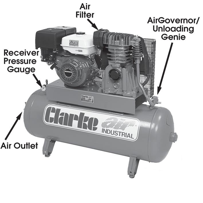
5 Fig.1-5 -
6 PREPARATION FOR USE A. Environmental Ensure the compressor is sited on a firm level surface. Ensure the environment is dry and dust free. Ensure there is adequate ventilation for: a) Air intake to compressor pump b) Cooling for compressor pump c) Engine exhaust gases. B. Engine Check oil and fuel levels and a visual check of components. Refer to engine service manual. C. Pump Check oil level on the Dipstick - to level marked. D. Fuelling Fill with unleaded petrol, according to the instructions within the engine manual. Ensure the fuel tap is set to the required position. Ensure The fuel hose and connectors are intact, in perfectly serviceable condition and there is no leakage. Note : Always use a funnel to fill the fuel tank so as to avoid accidental spillage of fuel. If fuel is spilled it must be removed from the unit and surrounding area, before attempting to start the engine. E. Receiver Drain off any condensate, by opening the drain cock (see Fig. 1). Remember to close the drain cock when completed. NOTE: This should be carried out DAILY when the compressor is in constant use. F. Air Hose & Air Tool Attach the air hose to the outlet using an appropriate connector. Attach the air tool/spray gun to the air hose...if using snap couplings, use a whip end, available from your Clarke dealer

7 STARTING THE COMPRESSOR 1. Open the drain cock and allow any condensate to drain compleatly, The drain cock in located on the bottom of the receiver tank. 2. Close the drain cock. 3. Fully open the bleed valve. 4. Connect the air hose to the air outlet. connect your air tool to the air hose. Ensure the air outlet tap is closed. 5. Start the engine, according to the instructions contained in the engine service manual, if this is the first time you use the compressor, allow to run for 10 minutes. 6. Close the bleed valve fully. Pressure will build up in the receiver and eventually the air governor will operate so that the engine runs off load. The pressure registered on the pressure gauge should be 100psi. 7. Use you air tool as indicated in its user guide Observe the pressure gauge. When the pressure has dropped by approx. 20psi, the Air Governor/Load Genie will operate and the compressor will cut in again. Fig.2 STOPPING THE COMPRESSOR 1. At the end of the day, stop the compressor in accordance with the engine manual. 2. Operate the air tool trigger or operating lever etc., to ensure there is no pressure in the air line, then disconnect airline and tool. WARNING! DO NOT under any circumstances attempt to remove the air tool or disconnect the air hose until you are satisfied that the pressure has been relieved. 3. Finally, open the drain cock very slowly to release the pressure in the tank. Take care not to touch the engine or pump as they remain hot for some time after use

8 MAINTENANCE DAILY a. Drain Air Receiver of any condensate b. Check engine oil level and top up where necessary. Ensure the dipstick breather hole is not blocked. c. Check pump oil level WEEKLY a. Clean Pump Air Filter Unbolt the Pump Air Filter cover and pull away to reveal foam element. If badly contaminated, replace. Remove any loose contaminants if any then replace. b. Clean the engine cooling fins. 6 MONTHLY Renew pump lubricating oil. Drain pump by removing the drain screw (Arrowed in Fig.3). Fig.3 Replace screw and top up until oil is level with the mark on the dipstick, using SAE40 oil available from your Clarke dealer as follows: Compressor oil - 1 litre: Part No Compressor oil - 5 litre: Part No In addition to the above, check the engine manual for service schedule. Repairs should only be carried out by a qualified engineer. If problems occur, contact your Clarke dealer
9 PUMP PARTS - 9 -
10 PUMP PARTS 15ND No. Description Part No. 1 Screw 2 Lower Cover 3 Casing 4 Bearing 5 Seal 6 Front Cover 7 Screw 8 Flywheel 9 Washer 10 Screw 11 Screw 12 Washer 13 Rear Cover 14 Oil Dipstick 15 Screw 16 Crankshaft 17 Connecting Rod 18 Piston Ring Kit 19 Circlip 20 Gudgeon Pin 21 Piston 22 Complete Piston 23 Cylinder 24 Valve Holder Plate 25 Head 26 Filter Cartridge 27 Intake Filter 28 Screw 29 Conveyor 30 Screw 31 Complete Seal Kit 32 Manifold 33 Automatic Discharge Valve

11 PARTS LIST HS17210-ZE1-822 HS17218-ZE1-821 HS HS28442-ZH HS28442-ZH HS28462-ZH mm Pressure Gauge Safety Valve Complete Drain Cock V-Belt Pump Complete (MK103) Pulley Engine complete (GX200QH) Manifold 3-way CBM Air Receiver
12 TROUBLE SHOOTING CHART IMPORTANT 1. Any remedial work that may be required must be carried out by a qualified engineer. 2. Switch off the engine before removing any parts from the compressor. 3. Drain the Air Receiver before dismantling any part of the compressor unit s pressure system. 4. If your compressor develops a fault do not use until the fault has been rectified. 5. For troubleshooting the engine, refer to the engine manual. SYMPTOM Engine difficult to start PROBABLE CAUSE Load Genie leaking (compressor unit is on load during start). Load Genie valve blocked, possibly frozen up. REMEDY Stop engine and empty air receiver. Clean or replace Load Genie Thaw Load Genie out (Unit must be installed in frost-free place). Compressor unit constantly on load Compressor constantly on load and cannot attain the working pressure required. Load Genie defective. Load Genie set at a pressure higher than the safety valve s opening pressure. Load Genie leaking. Suction filter blocked. Leak between compressor block and air receiver leaks in or near air receiver. Valves blocked by dirt, paint, dust or choked up. Inspection cover or drain plug leaking. Pressure gauge defective. Unit too small in relation to air consumption. Compressor worn. Have Load Genie serviced or replaced Clean / Change filter. Tighten connection and repair leak. Empty air receiver and change seals/plugs. Change pressure gauge. Use a larger capacity compressor Have compressor overhauled or replace it
13 Unusual noise from compressor. Compressor becomes too hot. Bolts loose. Flywheel loose. Unit installed on an unsuitable base. Bearings, piston rings or cylinder worn. Valve broken. Insufficient ventilation. Oil level too low (check 2 or 3 times after stopping). Fault in valves (machine not stopping). Blown head gasket (machine not stopping). Dirt on cooling fins or suction filter. Unit working at too high a pressure. Not fully unloading Tighten bolts - see page 16. Tighten flywheel. Move unit to a more solid base. See that sufficient air is supplied to flywheel or fan of compressor and that hot air is properly vented. Fill with oil see Page 10. Clean cooling fins and suction filter. Load genie partly blocked. Compressor being overworked and running continuously. Connect to a supplementary compressor or install a larger model
14 Compressor unit runs on and off load more frequently than usual. Large amount of condensation in air receiver. Leaks in system Drain off condensation Regularly (Every day before use). Locate leaks (by means of soapy water) and repair. Compressor unit runs on load when no air is being used. Leaks in system. Locate leaks (by means of soapy water) and repair. Compressor s oil consumption rising. Too much oil in compressor. Leaks around crank case. Check oil level 2 or 3 minutes after stopping. Working temperature of compressor too high because of insufficient cooling. Cylinder worn. Increase ventilation to air compressor. Intake air filter blocked. Clean or replace Oil in the air delivered. Sump over full. Cylinder worn. Reduce oil to correct level. Intake air filter blocked. Clean / Change air filter. Oil level rises although no oil has been put in. Condensation in oil pump. Compressor over dimensioned. Condensation at outlet points. Piping installation incorrect. Compressor taking in air which is too warm. Consult your local dealer. Obtain better fresh-air supply to compressor. Torque values for cylinder head bolts MODEL NUMBER Torque Vaule (NM) SP15ND
15 Notes

16
Air Compressor. Models: CFP9HND. Operating & Maintenance Instructions
 Air Compressor Models: CFP9HND Operating & Maintenance Instructions 0614 - 2 - WARNING! DO NOT ATTEMPT TO ALTER ENGINE SPEED SETTINGS DOING SO WILL INVALIDATE YOUR GUARANTEE SPECIFICATIONS CFP9ND Part
Air Compressor PP10ND PPH10ND PP15ND PPH15ND. Operating & Maintenance Instructions
 Air Compressor PP10ND PPH10ND PP15ND PPH15ND Operating & Maintenance Instructions 1002 SPECIFICATIONS PP10ND PPH10ND PP15ND PPH15ND Part Number 2090940 2090960 209080 2090100 WARNING! DO NOT ATTEMPT TO
Generator Set. CP Range. Operating & Maintenance Instructions 0702
 Generator Set CP Range Operating & Maintenance Instructions 0702 Read these safety instructions before using the equipment. Introduction Thank you for purchasing this Clarke portable Generator set. The
1100W PORTABLE GENERATOR
 1100W PORTABLE GENERATOR MODEL NO: G1200 PART NO: 8010110 OPERATION & MAINTENANCE INSTRUCTIONS LS0312 INTRODUCTION Thank you for purchasing this CLARKE 1100W Portable Generator. Before attempting to use
GENERATOR MODEL NO: FG3000 OPERATION & MAINTENANCE INSTRUCTIONS PART NO: LS0609
 GENERATOR MODEL NO: FG3000 PART NO: 8857700 OPERATION & MAINTENANCE INSTRUCTIONS LS0609 INTRODUCTION Thank you for purchasing this CLARKE Generator. Before attempting to use this product, please read this
720W PORTABLE GENERATOR
 720W PORTABLE GENERATOR MODEL NO: G720 PART NO: 8857800 OPERATION & MAINTENANCE INSTRUCTIONS LS0214 INTRODUCTION Thank you for purchasing this CLARKE 720W Portable Generator Before attempting to use this
6 Litre Oil-Less Air Compressor
 Operator s Manual 6 Litre Oil-Less Air Compressor WARNING! Before using this appliance, read the Operator s manual and follow all its safety rules and instructions. SPECIFICATION HWKAC1 1.1 kw / 1.5 HP
GENERATOR MODEL NO: FG4050ES / FG5100ES OPERATION & MAINTENANCE INSTRUCTIONS PART NO: , LS0310
 GENERATOR MODEL NO: FG4050ES / FG5100ES PART NO: 8857715, 8857720 OPERATION & MAINTENANCE INSTRUCTIONS LS0310 INTRODUCTION Thank you for purchasing this CLARKE Generator. Before attempting to use this
GENERATOR MODEL NO: FG3005 OPERATION & MAINTENANCE INSTRUCTIONS PART NO: LS0413
 GENERATOR MODEL NO: FG3005 PART NO: 8857707 OPERATION & MAINTENANCE INSTRUCTIONS LS0413 INTRODUCTION Thank you for purchasing this CLARKE Generator. Before attempting to use this product, please read this
HOT WASHER MODEL NO: KING 125 OPERATION & MAINTENANCE INSTRUCTIONS PART NO: LS1009
 HOT WASHER MODEL NO: KING 125 PART NO: 7320170 OPERATION & MAINTENANCE INSTRUCTIONS LS1009 INTRODUCTION Thank you for purchasing this Hot Washer. This machine is a portable, high pressure power washer,
GENERATOR MODEL NO: FG2500 OPERATION & MAINTENANCE INSTRUCTIONS PART NO: LS0114
 GENERATOR MODEL NO: FG2500 PART NO: 8857727 OPERATION & MAINTENANCE INSTRUCTIONS LS0114 INTRODUCTION Thank you for purchasing this CLARKE Generator. Before attempting to use this product, please read this
1200W INVERTER GENERATOR
 1200W INVERTER GENERATOR MODEL NO: IG1200 PART NO: 8877070 OPERATION & MAINTENANCE INSTRUCTIONS LS0117 INTRODUCTION Thank you for purchasing this CLARKE 1200W Inverter Generator. Before attempting to use
3KVA DUAL VOLTAGE GENERATOR MODEL NO: PG3800DV
 3KVA DUAL VOLTAGE GENERATOR MODEL NO: PG3800DV PART NO: 8857815 OPERATION & MAINTENANCE INSTRUCTIONS LS1016 INTRODUCTION Thank you for purchasing this CLARKE 3KVA Dual Voltage Generator. Before attempting
5.5KVA GENERATOR MODEL NO: PG6500DVES OPERATION & MAINTENANCE INSTRUCTIONS PART NO: LS0616
 5.5KVA GENERATOR MODEL NO: PG6500DVES PART NO: 8857810 OPERATION & MAINTENANCE INSTRUCTIONS LS0616 INTRODUCTION Thank you for purchasing this CLARKE 5.5KVA Generator. Before attempting to use this product,
Portable Oil Free Silent Series Compressor Operating Instructions
 Portable Oil Free Silent Series Compressor Operating Instructions NOTICE Carefully read this instruction manual before attempting to operate this compressor. MODEL # SERIAL # 1-800-551-2406 www.eaglecompressor.com
MONZA OIL FREE AIR COMPRESSOR OPERATION & MAINTENANCE INSTRUCTIONS
 MONZA OIL FREE AIR COMPRESSOR OPERATION & MAINTENANCE INSTRUCTIONS 0702 PARTS & SERVICE CONTACTS For Spare Parts and Service, please contact your nearest dealer, or CLARKE International, on one of the
6L Oil-less Air Compressor 53103
 6L Oil-less Air Compressor 53103 Operating Instructions Please read and save these instructions before attempting to assemble, install, operate or maintain the product. Protect yourself and others by observing
PRESSURISED SANDBLASTER
 PRESSURISED SANDBLASTER MODEL NO: CPSB200 PART NO: 7640128 OPERATION & MAINTENANCE INSTRUCTIONS LS1211 INTRODUCTION Thank you for purchasing this Clarke Pressurised Sandblaster. Before you try to use this
WARNING: Read these instructions before using the machine GENERATOR MODEL NO: IG3500F PART NO: OPERATION & MAINTENANCE INSTRUCTIONS
 WARNING: Read these instructions before using the machine GENERATOR MODEL NO: IG3500F PART NO: 8877100 OPERATION & MAINTENANCE INSTRUCTIONS ORIGINAL INSTRUCTIONS LS0217 INTRODUCTION Thank you for purchasing
AIR COMPRESSOR OPERATING INSTRUCTION AND PARTS LIST
 AIR COMPRESSOR OPERATING INSTRUCTION AND PARTS LIST BELT TYPE IMPORTANT PLEASE MAKE CERTAIN THAT THE PERSON WHO IS TO USE THIS EQUIPMENT CAREFULLY READS AND UNDERSTANDS THESE INSTRUCTIONS BEFORE STARTING
PETROL POWER WASHER MODEL NO: PLS195, PLS265 OPERATION & MAINTENANCE INSTRUCTIONS PART NO: , LS0616
 PETROL POWER WASHER MODEL NO: PLS195, PLS265 PART NO: 7330360, 7330365 OPERATION & MAINTENANCE INSTRUCTIONS LS0616 INTRODUCTION Thank you for purchasing this CLARKE Petrol Power Washer. Before attempting
SIP Direct Drive Oil-Lube Air Compressors - Operating & Maintenance Instructions
 SIP Direct Drive Oil-Lube Air Compressors - Operating & Maintenance Instructions Please read and fully understand the instructions in this manual before operation. Keep this manual safe for future reference.
PRESSURISED SANDBLASTER
 PRESSURISED SANDBLASTER MODEL NO: CPSB100 PART NO: 7640130 OPERATION & MAINTENANCE INSTRUCTIONS LS0510 INTRODUCTION Thank you for purchasing this Clarke Pressurised Sandblaster. Before you try to use this
OPERATION & MAINTENANCE INSTRUCTIONS
 WARNING Read the instructions before using the machine PETROL DRIVEN POWER WASHER MODEL NO: TIGER1700 PART NO: 7320054 OPERATION & MAINTENANCE INSTRUCTIONS LS0511 2 INTRODUCTION Thank you for purchasing
PETROL DRIVEN POWER WASHER
 WARNING: Read these instructions before using the machine PETROL DRIVEN POWER WASHER MODEL NO: TIGER 2500/2900 PART NO: 7320055/7320056 OPERATION & MAINTENANCE INSTRUCTIONS LS0513 INTRODUCTION Thank you
KING CANADA 950W PORTABLE GENERATOR MODEL: KCG-951G INSTRUCTION MANUAL COPYRIGHT 2011 ALL RIGHTS RESERVED BY KING CANADA TOOLS INC.
 KING CANADA 950W PORTABLE GENERATOR MODEL: KCG-951G INSTRUCTION MANUAL COPYRIGHT 2011 ALL RIGHTS RESERVED BY KING CANADA TOOLS INC. WARRANTY & SERVICE INFORMATION 1-YEAR LIMITED WARRANTY FOR THIS 950W
Petrol Driven Water Pump. Model No. CD1-1 Part No OPERATING & MAINTENANCE INSTRUCTIONS
 Petrol Driven Water Pump Model No. CD1-1 Part No. 7230034 OPERATING & MAINTENANCE INSTRUCTIONS Thank you for purchasing this Clarke CD1 petrol driven water pump. Before attempting to operate this pump
PETROL GENERATOR PGH2200, PGH3000, PGH6500 OWNER S MANUAL FOR YOUR SAFETY PLEASE READ THESE INSTRUCTIONS CAREFULLY AND RETAIN THEM FOR FUTURE USE.
 PETROL GENERATOR OWNER S MANUAL PGH2200, PGH3000, PGH6500 FOR YOUR SAFETY PLEASE READ THESE INSTRUCTIONS CAREFULLY AND RETAIN THEM FOR FUTURE USE. WARRANTY GENERATOR SAFETY This generator is covered by
PRESSURISED SANDBLASTER MODEL NO: CPSB200B
 PRESSURISED SANDBLASTER MODEL NO: CPSB200B PART NO: 7640134 OPERATION & MAINTENANCE INSTRUCTIONS ORIGINAL INSTRUCTIONS GC0218 ISS 1 INTRODUCTION Thank you for purchasing this CLARKE Pressurised Sandblaster.
RANGER 45 / 65 AIR COMPRESSOR
 RANGER 45 / 65 AIR COMPRESSOR OPERATION & MAINTENANCE INSTRUCTIONS 0506 SPECIFICATIONS Electrical Supply... 230V, 1Phase 50Hz Motor Rating... 1.5 HP Max. Air Pressure... 8 bar (115 lbf/in 2 ) Air Displacement...
PETROL GENERATOR SPG2200, SPG3000, SPG6500 OWNER S MANUAL FOR YOUR SAFETY PLEASE READ THESE INSTRUCTIONS CAREFULLY AND RETAIN THEM FOR FUTURE USE.
 PETROL GENERATOR OWNER S MANUAL SPG2200, SPG3000, SPG6500 FOR YOUR SAFETY PLEASE READ THESE INSTRUCTIONS CAREFULLY AND RETAIN THEM FOR FUTURE USE. WARRANTY This generator is covered by a 24 month warranty
Belt Driven Compressor Operation Manual Model No. SACBD-100
 Belt Driven Compressor Operation Manual Model No. SACBD-100 www.synairgy-eu.com Contents Important Notice 3 Preparation for Usage 3 Safety Guidelines 4-5 Caution 6 Brief Description 6 Compressor Overview
PRESSURISED SANDBLASTER MODEL NO: CPSB100B PART NO: OPERATION & MAINTENANCE INSTRUCTIONS
 PRESSURISED SANDBLASTER MODEL NO: CPSB100B PART NO: 7640133 OPERATION & MAINTENANCE INSTRUCTIONS ORIGINAL INSTRUCTIONS GC0218 ISS1 INTRODUCTION Thank you for purchasing this CLARKE Pressurised Sandblaster.
HYDRAULIC PALLET TRUCK. MODEL No: PTE550 PART Nos OPERATION & MAINTENANCE INSTRUCTIONS
 HYDRAULIC PALLET TRUCK MODEL No: PTE550 PART Nos 7630171 OPERATION & MAINTENANCE INSTRUCTIONS 0604 Please read these instructions carefully before operating the truck Thank you for purchasing this CLARKE
WARNING! Ensure that there are no naked flames around the product! Do not smoke while filling fuel and oil!
 Engine Oil and Fuel Engine Operation This product is equipped with a 4 stroke engine. Before operation you have to add proper fuel and engine oil. DO NOT MIXTURE THEM! 1. Place the product on a stable,
SPECIFICATIONS: Tank Size: 80 gallons PUMP RPMs: 1050 CFM: 40PSI; 90 PSI Max Pressure: 150 PSI Thermal overload protection
 5HP 80 GALLON TWO STAGE COMPRESSOR Models: 51866, 51870 CALIFORNIA PROPOSITION 65 WARNING: You can create dust when you cut, sand, drill or grind materials such as wood, paint, metal, concrete, cement,
EC DECLARATION OF CONFORMITY
 EC DECLARATION OF CONFORMITY 14 2500W INVERTER GENERATOR IM2500I CERTIFICATE OF GUARANTEE This product is guaranteed for a period of 1 Year, with effect from the date of purchase and applies only to the
Portable Electric/Gas Compressor Operating Instructions
 Portable Electric/Gas Compressor Operating Instructions NOTICE Carefully read this instruction manual before attempting to operate this compressor. MODEL # SERIAL # 1-800-551-2406 TABLE OF CONTENTS Safety
STENHØJ Piston compressors B-LINE type PL/TE/PE
 STENHØJ Piston compressors B-LINE type PL/TE/PE T63514 Rev.: 29-07-2005 Årgang 2005 Version :D User manual STENHØJ A/S DK-7150 Barrit +45 7682 1330 Fax +45 76 82 1331 Internet www.stenhoj.dk E-mail:infor@stenhoj.dk
SAFETY AND OPERATING MANUAL
 SAFETY AND OPERATING MANUAL COLD WATER PETROL WATER BLASTERS Read Safety & Operating Instructions Before Commencing Operation THESE INSTRUCTIONS MUST BE READ AND ADHERED TO BEFORE OPERATING THIS MACHINE.
Pump Owner s Manual. PLEASE! Read All Instructions Carefully Before Installing Pump
 Pump Owner s Manual PLEASE! Read All Instructions Carefully Before Installing Pump Guarantee Associate Engineering Corporation warrants that pumps purchased from them will be free of defects in material
PORTABLE SANDBLASTER HOPPER KIT MODEL NO: CPSB1
 PORTABLE SANDBLASTER HOPPER KIT MODEL NO: CPSB1 PART NO: 7640125 OPERATION & MAINTENANCE INSTRUCTIONS LS0309 INTRODUCTION Thank you for purchasing this Clarke Portable Sandblaster Hopper Kit. Before you
HYDRAULIC PALLET TRUCKS
 HYDRAULIC PALLET TRUCKS HYDRAULIC PALLET TRUCKS MODEL Nos: PT550 GAL & PT685 GAL PART Nos: 7630234 & 7630236 OPERATION & MAINTENANCE INSTRUCTIONS 0204 Please read these instructions carefully before operating
pressure washer 130bar 420ltr/hr 2.4hp petrol
 instructions for pressure washer 130bar 420ltr/hr 2.4hp petrol model no: PWM1300 Thank you for purchasing a Sealey product. Manufactured to a high standard, this product will, if used according to these
SPECIFICATIONS Horsepower: 1.5 HP Running Maximum PSI: 125 PSI Tank Capacity: 15 Gallons CFM: 6 40 PSI 5 90 PSI
 15 GALLON AIR COMPRESSOR Model: 7678 DO NOT RETURN TO STORE Please call 800-348-5004 for parts and service CALIFORNIA PROPOSITION 65 WARNING: You can create dust when you cut, sand, drill or grind materials
VT Oil-Free Range Operators Handbook
 VT Oil-Free Range Operators Handbook Covering Models:- VT7 / VT7D VT10 / VT10D VT200 / VT200D VT300 / VT300D VT00 / VT00D BAMBI AIR COMPRESSORS LTD 12 Thimble Mill Lane Heartlands Birmingham B7 HT Tel:
ENGINE DRIVEN 3 FULL TRASH PUMP
 ENGINE DRIVEN 3 FULL TRASH PUMP MODEL NO: PF75 PART NO: 7230165 OPERATION & MAINTENANCE INSTRUCTIONS ORIGINAL INSTRUCTIONS LS0117 ISS 2 INTRODUCTION Thank you for choosing this Clarke Pump. The function
Preventive maintenance 4
 00 Series Preventive maintenance Preventive maintenance periods Use the procedures in this chapter to maintain your engine in accordance with the preventive maintenance schedule. Check the periods given
LDG6000SA DIESEL GENERATOR OWNERS MANUAL
 LDG6000SA DIESEL GENERATOR OWNERS MANUAL BEFORE OPERATING THIS EQUIPMENT PLEASE READ THESE INSTRUCTIONS CAREFULLY Preface Thank-you for purchasing this generator. This operation manual contains information
AIR-COOLED DIESEL GENERATOR OWNERʼS MANUAL. This manual contains important safety information. TDG2500E TDGW7000E TDG7000SE TDG4500E
 AIR-COOLED DIESEL GENERATOR OWNERʼS MANUAL This manual contains important safety information. TDG2500E TDGW7000E TDG7000SE TDG4500E TDG8000-3 TDG7000SE-3 TDG7000E TDG8000E TDGW7000SE TDG7000E3 TDGW8000E
AC2T & AC2T-ES INDUSTRIAL GASOLINE AIR COMPRESSOR
 AC2T & AC2T-ES INDUSTRIAL GASOLINE AIR COMPRESSOR INDUSTRIAL GAS AIR COMPRESSOR OPERATOR S MANUAL IT IS ETREMELY IMPORTANT TO READ AND UNDERSTAND THE ENTIRE CONTENTS OF THIS OPERATOR S MANUAL BEFORE ATTEMPTING
ROYCE AIR COMPRESSOR 415VOLT/3 PHASE OPERATIONS MANUAL
 ROYCE AIR COMPRESSOR 415VOLT/3 PHASE OPERATIONS MANUAL PLEASE KEEP AND READ CAREFULLY BEFORE INSTALLING COMPRESSOR Table of Contents Unit Pictures & Descriptions 1 Warning 5 Installation 6 Starting, Run
TP300 INDUSTRIAL TRASH PUMP OPERATOR S MANUAL
 TP300 INDUSTRIAL TRASH PUMP OPERATOR S MANUAL IT IS EXTREMELY IMPORTANT TO READ AND UNDERSTAND THE ENTIRE CONTENTS OF THIS OPERATOR S MANUAL BEFORE ATTEMPTING TO OPERATE THE PRODUCT. THIS EQUIPMENT IS
1P88F-1 1P90F-1 1P92F-1. Owner's Manuel
 1P88F-1 1P90F-1 1P92F-1 Owner's Manuel EN 1 TABLE OF CONTENTS 1. General information... 1 2. Safety regulations... 1 3. Components and controls... 2 4. What you need to know... 3 5. Standards of use...
AC3020B AC3030B PORTABLE AIR
 AC3020B AC3030B PORTABLE AIR operation manual CAUTION READ THIS MANUAL CAREFULLY before operating or servicing this air compressor, to familiarize yourself with the proper safety, operation, and standard
5 LITRE HAND SPRAYER
 5 LITRE HAND SPRAYER MODEL NO: 5LS PART NO: 3402264 USER INSTRUCTIONS ORIGINAL INSTRUCTIONS GC0718 - ISS 1 INTRODUCTION Thank you for purchasing this CLARKE Sprayer, designed for use with insecticides
PF-4000, PF-4010, PF-4210 MULTI-PURPOSE ENGINE
 PF-4000, PF-4010, PF-4210 MULTI-PURPOSE ENGINE Date 09-26-01 Supplier To The Outdoor Power Equipment Industry ISM, Inc. 1028 4 th Street SW Auburn, WA 98001 Phone: (253) 333-1200 Fax: (253) 333-1212 WWW.TANAKA-USA.COM
Genquip Gi1000 Digital Inverter Petrol Generator. Owners Manual
 Owners Manual page 1 Notes page 2 Table of Contents Control Function 4 Pre Operation Checklist 5 Fuel System Check Fuel Level Control Function 6 Engine Oil Oil Warning System Engine Switch DC Protector
Owner s/operator s Manual
 Water Pump MP2533E2 Owner s/operator s Manual Completely read and understand this manual before using this product. Foreword This Owner s/ Operator s Manual is designed to familiarize the operator with
Instruction Manual. Vibratory Reversible Plate Compactor
 Instruction Manual Vibratory Reversible Plate Compactor Model VPR300 Model VPR400 Foreword This manual has been written to help you operate your Vibratory Reversible Compactor safely. It is intended primarily
DIRECT-DRIVE PRESSURE WASHERS
 DIRECT-DRIVE PRESSURE WASHERS PJG SERIES PRESSURE WASHER MANUFACTURED BY: PJG-2002B PJG-2502-6.5B PJG-3002B PJG-4002B INTRODUCTION Thank you for purchasing a Mancorp Pressure Washer. This manual covers
GENERATOR MODEL NO: DG6000DVES OPERATION & MAINTENANCE INSTRUCTIONS PART NO: LS1216
 GENERATOR MODEL NO: DG6000DVES PART NO: 8675000 OPERATION & MAINTENANCE INSTRUCTIONS LS1216 INTRODUCTION Thank you for purchasing this CLARKE Generator. Before attempting to use this product, please read
20 TONNE HYDRAULIC PRESS MODEL NO: CSA20FBT
 20 TONNE HYDRAULIC PRESS MODEL NO: CSA20FBT PART NO: 7614058 OPERATION & MAINTENANCE INSTRUCTIONS WARNING: Read these instructions before using the press GC0516 INTRODUCTION Thank you for purchasing this
2¼ TONNE TROLLEY JACK
 2¼ TONNE TROLLEY JACK Model No: CTJ2250LP PART NO: 7623070 OPERATING & MAINTENANCE INSTRUCTIONS GC01/12 INTRODUCTION Thank you for purchasing this CLARKE Trolley Jack. Before attempting to use this product,
HYDRAULIC PALLET TRUCK MODEL NO: PT540M/BM/CM & PT685BM/CM PART NO: , , , ,
 HYDRAULIC PALLET TRUCK MODEL NO: PT540M/BM/CM & PT685BM/CM PART NO: 7631700, 7631705, 7631710, 7631715, 7631720 OPERATION & MAINTENANCE INSTRUCTIONS LS0316 INTRODUCTION Thank you for purchasing this CLARKE
CROMMELINS COMPACTORS
 CROMMELINS COMPACTORS OPERATION & INSTRUCTION MANUAL Thank you for your selection of a CROMMELINS Compactor. This Operation Manual explains its use, installation, checking and maintenance. We highly recommend
12v / 24v Diesel Transfer Pump Kit
 Please dispose of packaging for the product in a responsible manner. It is suitable for recycling. Help to protect the environment, take the packaging to the local amenity tip and place into the appropriate
RedGum GP160 Splitter. Owner s Manual
 RedGum GP160 Splitter Owner s Manual Product Description & Intended Purpose: This Log Splitter / Wood Splitter is an outdoor product that splits wood logs for use as fuel in a fireplace or a woodstove.
110 Volt/12 Volt Portable Inflator
 110 Volt/12 Volt Portable Inflator Owner s Manual WARNING: Read carefully and understand all ASSEMBLY AND OPERATION INSTRUCTIONS before operating. Failure to follow the safety rules and other basic safety
DYNAPAC CONCRETE EQUIPMENT RAMIRENT. BG70 Power Floats INSTRUCTIONS & SPARE PARTS CATALOGUE BG70 - IS ENG
 DYNAPAC CONCRETE EQUIPMENT INSTRUCTIONS & SPARE PARTS CATALOGUE BG70 Power Floats BG70 - IS - 10682 - ENG SAFETY INSTRUCTIONS - MACHINES SUBMITTED : Powered with : Electric, Pneumatic, Petrol or Diesel
MTD OHV Series FORM NO B. jqa=mêççìåíë=^âíáéåöéëéääëåü~ñí= =p~~êäêωåâéå= =déêã~åó
 MTD OHV Series J15 FORM NO. 769-08890B jqa=mêççìåíë=^âíáéåöéëéääëåü~ñí= =p~~êäêωåâéå= =déêã~åó 4 11 19 27 35 43 51 58 65 72 79 87 96 104 112 119 126 134 141 148 155 162 171 179 188 197 206 213 221
Read instructions carefully and follow rules for safe operation. Failure to do so could result in serious injury. Fradan Manufacturing Corp.
 OPERATOR MANUAL FRADAN POWER BLOWERS Part No. 888-011-222-0 Read instructions carefully and follow rules for safe operation. Failure to do so could result in serious injury. Fradan Manufacturing Corp.
Medusa T1101 Generator
 Please dispose of packaging for the product in a responsible manner. It is suitable for recycling. Help to protect the environment, take the packaging to the local amenity tip and place into the appropriate
40041 Heavy Duty ADA System with Booster Bracket for JK Heavy Duty ADA System with Booster Bracket for 2012 to Current JK
 40041 Heavy Duty ADA System with Booster Bracket for 2007-2011 JK 40044 Heavy Duty ADA System with Booster Bracket for 2012 to Current JK 40049 Heavy Duty ADA System Universal for all vehicles (booster
80 Litre Suction Oil Drainer With Inspection Chamber
 Please dispose of packaging for the product in a responsible manner. It is suitable for recycling. Help to protect the environment, take the packaging to the local amenity tip and place into the appropriate
1/4 Die Grinder. Please read and fully understand the instructions in this manual before operation. Keep this manual safe for future reference
 Please dispose of packaging for the product in a responsible manner. It is suitable for recycling. Help to protect the environment, take the packaging to the local amenity tip and place into the appropriate
IMPORTANT: Read this manual fully before assembly and use and observe all safety rules and operating instructions
 PETROL ENGINE Model: MLR52 IMPORTANT: Read this manual fully before assembly and use and observe all safety rules and operating instructions Contents Technical Specification 2 Safety 3 Starting 5 Running
2 TONNE TROLLEY JACK
 2 TONNE TROLLEY JACK Model No: CTJ2000LP PART NO: 7623065 OPERATING & MAINTENANCE INSTRUCTIONS GC01/12 INTRODUCTION Thank you for purchasing this CLARKE Trolley Jack. Before attempting to use this product,
INVERTER GENERATOR OWNER S MANUAL FOR YOUR SAFETY PLEASE READ THESE INSTRUCTIONS CAREFULLY AND RETAIN THEM FOR FUTURE USE.
 INVERTER GENERATOR OWNER S MANUAL FOR YOUR SAFETY PLEASE READ THESE INSTRUCTIONS CAREFULLY AND RETAIN THEM FOR FUTURE USE. GENERATOR SAFETY Only use outdoors! Never use during wet conditions! Do not smoke
DIAPHRAGM PUMPS: Instruction Manual
 INTRODUCTION DIAPHRAGM PUMPS: Instruction Manual Congratulations for choosing a product Imovilli Pompe, the result of a careful manufacturing process supported by over fifty years of specific experience
5 IN 1 JUMP START OPERATION & MAINTENANCE INSTRUCTIONS MODEL NO: JS5IN1 PART NO: LS0810
 5 IN 1 JUMP START MODEL NO: JS5IN1 PART NO: 6240005 OPERATION & MAINTENANCE INSTRUCTIONS LS0810 INTRODUCTION Thank you for purchasing this CLARKE product. Before attempting to use this product, please
Rescue Pac. Please read and fully understand the instructions in this manual before operation. Keep this manual safe for future reference
 Please dispose of Packaging for the product in a responsible manner. It is suitable for recycling. Help to protect the environment, take the packaging to the local amenity tip and place into the appropriate
3 Petrol Water Pump. Please read and fully understand the instructions in this manual before operation. Keep this manual safe for future reference
 Please dispose of packaging for the product in a responsible manner. It is suitable for recycling. Help to protect the environment, take the packaging to the local amenity tip and place into the appropriate
AG-HA-2500N GASOLINE GENERATOR
 AG-HA-2500N GASOLINE GENERATOR OWNER S MANUAL BEFORE OPERATING THIS EQUIPMENT PLEASE READ THESE INSTRUCTIONS CAREFULLY (I)WARNING 1. Read the operator s instruction manual. 2. Attention! Exhaust gases
OIL DRAINER MODEL No: COD70. Part No: ASSEMBLY and OPERATING INSTRUCTIONS 0707
 OIL DRAINER MODEL No: COD70 Part No: 7630203 ASSEMBLY and OPERATING INSTRUCTIONS 0707 Thank you for purchasing this Clarke Oil Drainer, which is designed to provide a means of draining vehicle oil quickly
OPERATION & MAINTENANCE MANUAL
 Aussie Pumps Cougar MkII Pressure Blaster OPERATION & MAINTENANCE MANUAL Feb 2012 IMPORTANT: TO REDUCE RISK OF INJURY, READ OPERATING INSTRUCTIONS CAREFULLY BEFORE USING EQUIPMENT Aussie Pumps Feb 2012
Iron Horse Air Compressor part breakdown - IHD6160V1 Item Description IHD6160V1 IHD6160V1 Call for the Customer Service Department.
 Iron Horse Air Compressor part breakdown - IHD6160V1 Item Description IHD6160V1 1 Compressor w/ Flywheel CC2065 2 Discharge Tube w/ Fittings TU-23-AL 3 Pressure Gauge PG200-2.5R 4 Air Receiver 60V20X48SPL
Table of Contents. Safety Assembly Pre-operation / Starting. 7. Operation.. 8. Maintenance. 9. Storage 10
 Table of Contents Safety... 3 Assembly... 6 Pre-operation / Starting. 7 Operation.. 8 Maintenance. 9 Storage 10 Parts drawings..11 Parts list by number..12 Notes.13 2 Safety Information Attention; this
GARAGE JACK MODEL NO: CTJ3000G PART NO: OPERATION & MAINTENANCE INSTRUCTIONS ORIGINAL INSTRUCTIONS
 GARAGE JACK MODEL NO: CTJ3000G PART NO: 7623030 OPERATION & MAINTENANCE INSTRUCTIONS ORIGINAL INSTRUCTIONS GC1217 INTRODUCTION Thank you for purchasing this CLARKE Garage Jack. Before attempting to use
Routine Compressor Maintenance
 Establishing a regular, well-organized maintenance program and strictly following it is critical to maintaining the performance of a compressed air system. One person should be given the responsibility
Medusa Trade T2401 Generator
 Please dispose of packaging for this product in a responsible manner. It is suitable for recycling. Help to protect the environment, take the packaging to the local amenity tip and place into the appropriate
GARAGE JACK MODEL NO: CTJ3000QLB PART NO: OPERATION & MAINTENANCE INSTRUCTIONS ORIGINAL INSTRUCTIONS
 GARAGE JACK MODEL NO: CTJ3000QLB PART NO: 7623205 OPERATION & MAINTENANCE INSTRUCTIONS ORIGINAL INSTRUCTIONS GC1216 2 INTRODUCTION Thank you for purchasing this CLARKE Garage Jack. Before attempting to
SUBMERSIBLE PUMP HSE RANGE
 SUBMERSIBLE PUMP HSE RANGE OPERATION & MAINTENANCE INSTRUCTIONS 0806 SPECIFICATIONS Model No. HSE120* HSE200 HSE300*/ HSE360*/ HSEC400* HSE301 HSE361 Outlet Dia. (mm/inches) 32/1-1/4 38/1-1/2 50/2 50/2
2 TONNE GARAGE JACK Model No: CTJ2QLP PART NO:
 TONNE GARAGE JACK Model No: CTJQLP PART NO: 7680 OPERATING & MAINTENANCE INSTRUCTIONS GC03 INTRODUCTION Thank you for purchasing this CLARKE Garage Jack. Before attempting to use this product, please read
230V DIESEL FUEL TRANSFER PUMP MODEL NO: DFT230
 230V DIESEL FUEL TRANSFER PUMP MODEL NO: DFT230 PART NO: 7160050 OPERATION & MAINTENANCE INSTRUCTIONS GC0816 INTRODUCTION Thank you for purchasing this CLARKE Pump. The DFTP230 pump is a self-priming rotary
AND OPERATING INSTRUCTIONS IMPORTANT:
 WOOD CHIPPER User Manual FM6.5WC SAFETY AND OPERATING INSTRUCTIONS IMPORTANT: Read safety rules and instructions carefully before operating equipment. Table of Contents Table of Contents PART I: General
Brushcutters. Bent Shaft Brushcutter. Straight Shaft Brushcutter BCS260 BCB260
 Brushcutters BCB260 Bent Shaft Brushcutter BCS260 Straight Shaft Brushcutter Please read this instruction manual carefully before operating your new Sanli Brushcutter. Congratulations on choosing a Sanli
AIR/HYDRAULIC LIFT TABLE CART 770-LB.
 AIR/HYDRAULIC LIFT TABLE CART 770-LB. OWNER S MANUAL WARNING: Read carefully and understand all MACHINE ADJUSTMENT AND OPERATION INSTRUCTIONS before operating. Failure to follow the safety rules and other
PROFESSIONAL CORDLESS IMPACT SCREWDRIVER
 PROFESSIONAL CORDLESS IMPACT SCREWDRIVER Model CIS00 Part No 4500625 OPERATING & MAINTENANCE INSTRUCTIONS GC0309 INTRODUCTION Thank you for purchasing this CLARKE Impact Screwdriver. Before attempting
Gasoline Inverter Generator
 user manual Gasoline Inverter Generator table of contents Preface Introduction... Safety Information Exhaust fumes are poisonous... Fuel is highly flammable and poisonous... Engine and muffler may be hot...