Form No Operator s Manual. Asphalt Paver. Beginning with Serial Number Gehl Company All Rights Reserved.
|
|
|
- Opal Booth
- 6 years ago
- Views:
Transcription


1 Form No Asphalt Paver Beginning with Serial Number Gehl Company All Rights Reserved. Printed in USA Operator s Manual
2 Indicator and Operation Symbols Engine Start Engine Stop Electrical Power Glow Plug Glow Plug Indicator Battery Charge Engine Oil Pressure Engine Coolant Temperature Slow Fast Engine Rotational Speed Diesel Fuel Sprayer On Sprayer Off Sprayer Wand Read Operator s Manual Safety Hourmeter Horn
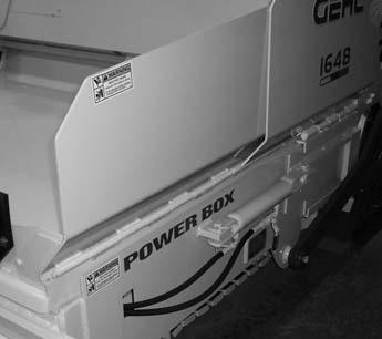
3 Table of Contents Chapter Description Page International Symbols Inside Front Cover 1 Introduction Specifications Check Lists SAFETY Indicators and Controls Operation and Adjustments Lubrication Service and Storage Maintenance Troubleshooting Decal Locations Index Standard Hardware Torque Data Warranty Inside Back Cover IDENTIFICATION INFORMATION Write the Gehl Power Box Paver model and serial number in the space provided below. Refer to these numbers when inquiring about parts or service from your Gehl dealer The model and serial numbers for this machine are on a decal located on the back wall. PRINTED IN U.S.A /AP0206
4 Chapter 1 INTRODUCTION The information in this Operator s Manual was written to give the owner/operator assistance in preparing, adjusting, maintaining and servicing of the Paver. More important, this manual provides an operating plan for safe and proper use of the machine. Major points of safe operation are detailed in the SAFETY chapter of this manual. GEHL Company asks that you read and understand the contents of this manual COMPLETELY and become familiar with the machine, before operating it. The use of this Paver is subject to certain hazards that cannot be eliminated by mechanical means, but only by the exercise of intelligence, care and common sense. It is therefore essential to have competent and careful operators, who are not physically or mentally impaired, and who are thoroughly trained in the safe operation of the equipment. Throughout this manual information is provided that is set in italic type and introduced by the word IMPORTANT or NOTE. Be sure to read carefully and comply with the message or directive given. Following this information will improve operating and maintenance efficiency, help to avoid breakdowns and damage, and extend the machine s life. A chart of standard hardware torques is located in the back of this manual. A storage area is provided on the unit for storing the Operator s Manual. After using the manual, please return it to the storage area and keep it with the unit at all times! If this machine is resold, GEHL Company recommends that this manual be given to the new owner. If this machine was purchased "used," or if the owner's address has changed, please provide your GEHL dealer or GEHL Company Service Department with the owner's name and current address, along with the machine model and serial number. This will allow the registered owner information to be updated, so that the owner can be notified directly in case of an important product issue, such as a safety update program. Right and left are determined from a position standing on the screed and facing forward. The wide GEHL dealership network stands ready to provide any assistance that may be required, including genuine GEHL service parts. All parts should be obtained from or ordered through your GEHL dealer. Give complete information about the part and include the model and serial number of the machine. Record the serial number in the space provided on the previous page, as a handy record for quick reference. GEHL Company reserves the right to make changes or improvements in the design or construction of any part without incurring the obligation to install such changes on any unit previously delivered. GEHL Company, in cooperation with the Society of Automotive Engineers, has adopted this Safety Alert Symbol to identify potential safety hazards, which, if not properly avoided, could result in injury. When you see this symbol in this manual or on the machine itself, you are reminded to BE ALERT! Your personal safety is involved! /AP PRINTED IN U.S.A.
 LEFT HAND CONTROL LEVERS PUMP CONTROL LEVER CONTROL PANEL FUEL TANK FILLER CAP AIR CLEANER RIGHT HAND CONTROL LEVERS")

5 Paver Identification WASHDOWN SPRAY WAND (EA. SIDE) LEFT HAND CONTROL LEVERS PUMP CONTROL LEVER CONTROL PANEL FUEL TANK FILLER CAP AIR CLEANER RIGHT HAND CONTROL LEVERS RADIATOR FILL MODULAR STEERING OIL COOLER LOWER PLATFORM PROPANE TANK MOUNT SCREED ENGINE and HYD. PUMP UPPER PLATFORM SCREED ADJUST SCREW (EA. SIDE) EXHAUST MUFFLER HOPPER AND HOPPER WINGS PUSH ROLLERS SCREED EXTENSION SIDE GATE DRIVE TRACK (EA. SIDE) HYDRAULIC RESERVOIR (LOWER FRAME) PRINTED IN U.S.A /AP0206
6 Chapter 2 SPECIFICATIONS Gehl Power Box Paver Model 1648 Augers on Screed Augers on Gates General Dimensions: Length ft. 7 in. (2921 mm) 9 ft. 2 in. (2794 mm) Minimum Width (transport) ft. 6 in. (2590 mm) 8 ft. 6 in. (2590 mm) Maximum Width (operating) ft. 6 in. (4115 mm) 13 ft. 6 in. (4115 mm) Overall Height (top of exhaust pipe) ft. 6 in. (2286 mm) 7 ft. 6 in. (2286 mm) Weight (approximate) ,350 lbs. (4241 kg) 9,350 lbs. (4241 kg) Truck Clearance (height from ground to asphalt hopper floor) in. (585 mm) 23 in. (585 mm) Screed: Maximum Variable Crown/Invert 3 in. / 2 in. 3 in. / 2 in. (76 mm / 51 mm) (76 mm / 51 mm) Main Width in. (330 mm) 13 in. (330 mm) Extension Width in. (152 mm) 6 in. (152 mm) Hydraulic Vibrator Hz 50 Hz Heat Medium Propane Propane Variable Hydraulic Screed Extension - Max. Extension Length in. (762 mm) 30 in. (762 mm) Dual Span Operator Platform Type Isolated Isolated Top Operator Platform Type Stationary Stationary Service Capacities: Engine Cooling System (Isuzu - 4LC1) qts. (6.4 L) 6.8 qts. (6.4 L) Engine Oil w/filter (Isuzu - 4LC1) qts. (6.5 L) 6.9 qts. (6.5 L) Hydraulic Reservoir gal. (75.7 L) 20 gal. (75.7 L) Fuel Tank gal. (45.4 L) 12 gal. (45.4 L) Washdown Tank w/electric Pump gal. (20.8 L) 5.5 gal. (20.8 L) Engine: Drive System: Isuzu - 4LC1, 41 hp (30.6 kw) Water-Cooled Diesel with 12-Volt Electric Starter, 35-Amp Alternator, 575-CCA Battery Hydrostatic, Steel Track, Positive/Self-Adjusting, Counter-Rotating, Fine-Tune Steering Valve /AP PRINTED IN U.S.A.
7 SPECIFICATIONS (Continued) Gehl PowerBox Paver Model 1648 Augers on Screed Augers on Gates Hydraulic System: Variable Hydrostatic Drive Pump - Maximum Flow gpm (140 L/min) 37 gpm (140 L/min) Variable Hydrostatic Drive Pump - Maximum Relief Pressure psi (24.5 bar) 3500 psi (24.5 bar) Hydraulic Auger Drive Pump - Maximum Flow gpm (41.6 L/min) 11 gpm (41.6 L/min) Hydraulic Auger Drive Pump - Maximum Relief Pressure psi (14 bar) 2000 psi (14 bar) Hydraulic Cylinder Pump - Maximum Flow gpm (41.6 L/min) 11 gpm (41.6 L/min) Hydraulic Cylinder Pump - Maximum Relief Pressure psi (126 bar) 1800 psi (126 bar) Return Filter Micron 5 Micron Suction Strainer Micron 100 Micron Auxiliary Oil Cooler Capacity gpm (45.4 L/min) 12 gpm (45.4 L/min) Drive Loop Oil Cooler Capacity gpm (75.7 L/min) 20 gpm (75.7 L/min) Paving Performance: Minimum Variable Paving Width ft. (2438 mm) 8 ft. (2438 mm) Maximum Variable Paving Width ft. (3962 mm) 13 ft. (3962 mm) Minimum Variable Paving Depth /2 in. (0-13 mm) 0-1/2 in. (0-13 mm) Maximum Variable Paving Depth in. (152 mm) 6 in. (152 mm) Gravity Feed Hopper Capacity Tons (5443 kg) 6 Tons (5443 kg) Hydraulic Feed Augers Hydraulic Material Flow Gates Operating Speed fpm (0-40 m/min) fpm (0-40 m/min) Left and Right Side Operator Controls Standard Standard PRINTED IN U.S.A /AP0206
8 INTENTIONALLY BLANK /AP PRINTED IN U.S.A.
9 Chapter 3 CHECKLISTS PRE-DELIVERY The following Checklist is an important reminder of valuable information and inspections that MUST be made before delivering the Paver to the customer. Check off each item after prescribed action is taken. Check that: No parts of Paver have been damaged in shipment. Check for such things as dents and loose or missing parts; correct or replace components as required. Battery is securely mounted and not cracked. Cable connections are tight. Electrolyte at proper level. Cylinders, hoses and fittings are not damaged, leaking or loosely secured. Oil, fuel and air filters are not damaged leaking or loosely secured. All grease fittings have been properly lubricated and no fittings are missing; see LUBRICATION chapter of this manual. Hydraulic system reservoir, engine crankcase, and engine coolant are filled to the proper operating levels. All adjustments have been made to comply with the settings given in this manual and in the separate engine manual. All guards, shields and decals are in place and securely attached. Model and serial number for this unit are recorded in space provided on this page and page 1. Start the Paver and test-run the unit while checking that proper operation is exhibited by all controls. Check that: All indicators (lamps, meters, etc.) function properly. Proper operation of all hopper and screed controls. Dynamic braking in effect with drive motors in neutral. No hydraulic system leaks when under pressure. Listen for abnormal noises or vibrations; if detected, determine their cause and repair as necessary. I acknowledge that pre-delivery procedures were performed on this unit as outlined above. Dealership s Name Dealer Representative s Name Date Checklist Filled Out Machine Model # Machine Serial # Engine Serial # DELIVERY The following Checklist is an important reminder of valuable information that MUST be passed on to the customer at the time the unit is delivered. Check off each item as you explain it to the customer. Check that: Review with the customer the contents of this manual; especially: The INDEX at the back, for quickly locating topics; The SAFETY, INDICATORS AND CONTROLS, and OPERATION AND ADJUSTMENTS chapters for information regarding safe use of the machine. The LUBRICATION, SERVICE AND STORAGE and TROUBLESHOOTING chapters, for information regarding proper maintenance of the machine. Explain that regular lubrication and maintenance are required for continued safe operation and long life. Give this Operator s Manual to the customer and instruct them to be sure to read and completely understand its contents before operating the unit. Explain that the customer must consult the engine manual (provided) for related specifications, operating adjustments and maintenance instructions. Completely fill out the Owner s Registration, including customer s signature, and return it to the Company. Customer s Signature Date Delivered (Dealer s File Copy - Remove at Perforation) PRINTED IN U.S.A /AP0206
10 INTENTIONALLY BLANK (To be removed as Dealer s file copy) /AP PRINTED IN U.S.A.
11 Chapter 3 CHECKLISTS PRE-DELIVERY The following Checklist is an important reminder of valuable information and inspections that MUST be made before delivering the Paver to the customer. Check off each item after prescribed action is taken. Check that: No parts of Paver have been damaged in shipment. Check for such things as dents and loose or missing parts; correct or replace components as required. Battery is securely mounted and not cracked. Cable connections are tight. Electrolyte at proper level. Cylinders, hoses and fittings are not damaged, leaking or loosely secured. Oil, fuel and air filters are not damaged leaking or loosely secured. All grease fittings have been properly lubricated and no fittings are missing; see LUBRICATION chapter of this manual. Hydraulic system reservoir, engine crankcase, and engine coolant are filled to the proper operating levels. All adjustments have been made to comply with the settings given in this manual and in the separate engine manual. All guards, shields and decals are in place and securely attached. Model and serial number for this unit are recorded in space provided on this page and page 1. Start the Paver and test-run the unit while checking that proper operation is exhibited by all controls. Check that: All indicators (lamps, meters, etc.) function properly. Proper operation of all hopper and screed controls. Dynamic braking in effect with drive motors in neutral. No hydraulic system leaks when under pressure. Listen for abnormal noises or vibrations; if detected, determine their cause and repair as necessary. I acknowledge that pre-delivery procedures were performed on this unit as outlined above. Dealership s Name Dealer Representative s Name Date Checklist Filled Out Machine Model # Machine Serial # Engine Serial # DELIVERY The following Checklist is an important reminder of valuable information that MUST be passed on to the customer at the time the unit is delivered. Check off each item as you explain it to the customer. Check that: Review with the customer the contents of this manual; especially: The INDEX at the back, for quickly locating topics; The SAFETY, INDICATORS AND CONTROLS, and OPERATION AND ADJUSTMENTS chapters for information regarding safe use of the machine. The LUBRICATION, SERVICE AND STORAGE and TROUBLESHOOTING chapters, for information regarding proper maintenance of the machine. Explain that regular lubrication and maintenance are required for continued safe operation and long life. Give this Operator s Manual to the customer and instruct them to be sure to read and completely understand its contents before operating the unit. Explain that the customer must consult the engine manual (provided) for related specifications, operating adjustments and maintenance instructions. Completely fill out the Owner s Registration, including customer s signature, and return it to the Company. Customer s Signature Date Delivered (Pages 7 and 8 have been removed at perforation) PRINTED IN U.S.A /AP0206
12 Chapter 4 SAFETY The above Safety Alert Symbol means ATTENTION! ALWAYS BE ALERT! YOUR SAFETY IS INVOLVED! It stresses an attitude of Heads Up for Safety and can be found throughout this Operator s Manual and the machine itself. Before operating this equipment, read and study the following safety information. In addition, be sure that everyone who operates or works with this equipment, whether family member or employee, is familiar with these safety precautions. The Gehl Company always takes the operator s safety into consideration when designing its machinery and guards exposed moving parts for his/her protection. However, some areas cannot be guarded or shielded in order to assure proper operation. Further, this Operator s Manual and decals on the machine warn of additional hazards and should be read and observed closely. DANGER DANGER indicates an imminently hazardous situation which, if not avoided, will result in death or serious injury. WARNING WARNING indicates a potentially hazardous situation which, if not avoided, could result in death or serious injury. CAUTION CAUTION indicates a potentially hazardous situation which, if not avoided, may result in minor injury or property damage. It also alerts users to unsafe practices. It is the owner s responsibility for communicating information on the safe use and proper maintenance of this machine! This includes providing understandable interpretation of these instructions for operators who are not fluent in reading English. It is the responsibility of the operator to read and understand the Operator s Manual and other information provided and use correct operating procedures. Machines should be operated only by qualified operators. MANDATORY SAFETY SHUTDOWN PROCEDURE BEFORE cleaning, adjusting, lubricating or servicing the unit: 1. Bring machine to full parking stop on level surface (NEVER park on a slope or hillside). 2. Lower the hopper and screed assembly to the full down position. 3. Place all controls in neutral. 4. Move the throttle to low idle. 5. Shut off the engine and remove the key. ONLY when you have taken these precautions can you be sure it is safe to proceed. Failure to follow the above procedure could lead to death or serious injury. Additional Safety Reminders User/operator safety practices, as established by industry standards, are included in this Operator s Manual and intended to promote safe operation of the Paver. These guidelines do not preclude the use of good judgment, care and common sense, as may be indicated by the particular jobsite work conditions. It is essential that operators be physically and mentally free of mind altering drugs and chemicals and /AP PRINTED IN U.S.A.
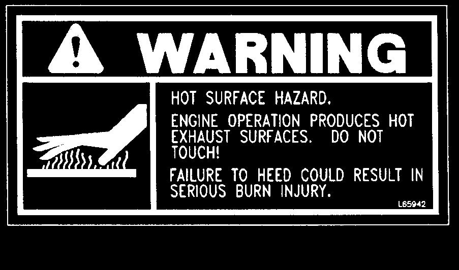
13 SAFETY (Continued) thoroughly trained in the safe operation of the Paver. Such training should be presented completely to all new operators and not condensed for those claiming previous experience. Information on operator training is available from several sources, including the manufacturer. Some illustrations used in this manual may show doors, guards and shields open or removed for illustration purposes only. Be sure that all doors, guards and shields are in their proper operating positions before starting the engine to operate the Paver. Before Operation Safety Reminders Always wear appropriate personal protective equipment called for by the job or working conditions. Hard hats, safety glasses, protective shoes, gloves, reflective vests, respirators and ear protection are examples of types of equipment that may be required. Do not wear loose fitting clothing, long hair, jewelry or loose personal items while operating or servicing the machine. ALWAYS check the job site for obstructions and bystanders! Operation Safety Reminders Do not attempt to move hot asphalt mix with your hands or feet. Contact can cause serious skin burns. Do not allow minors or any unqualified personnel to operate or be near the Paver unless properly supervised. Do not operate the Paver in an enclosed area without adequate ventilation! Internal combustion engines deplete the oxygen supply within enclosed spaces and may create a serious hazard unless the oxygen is replaced. Do not leave the Paver unattended with the engine running. ALWAYS lower the hopper to full down position, shut off the engine and place all controls in neutral before leaving the machine. Operation Safety Reminders NEVER use your hands to search for hydraulic fluid leaks. Use a piece of paper or cardboard. Escaping fluid under pressure can be invisible and can penetrate the skin causing serious injury. If any fluid is injected into your skin, see a doctor at once. Injected fluid MUST be surgically removed by a doctor familiar with this type of injury or gangrene may result! ALWAYS position the safety props up when leaving the hopper raised for inspection, cleaning or service! Do not refill the fuel reservoir when the engine is hot. Allow engine to cool down before refilling to prevent hot engine from igniting the fuel if it should spill or splash. Do not smoke while filling the fuel tank, while working on the fuel or hydraulic systems, or while working around the battery. Do not attempt to loosen or disconnect any hydraulic lines, hoses or fittings without first relieving hydraulic circuit pressure. Also, be careful not to touch any hydraulic components that have been in recent operation, because they can be extremely hot and can burn you. Always disconnect the battery connection to prevent unintentional starting while working on this machine. Do not attempt to remove the radiator cap after the engine has reached operating temperature or if it is overheated. At operating temperatures, the engine coolant will be extremely hot and under pressure. Always wait for the engine to cool down before attempting to relieve pressure and remove the radiator cap. Failure to heed this warning could result in severe burns. PRINTED IN U.S.A /AP0206
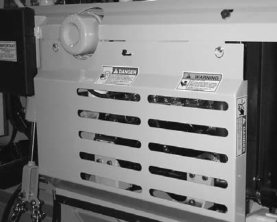
14 SAFETY (Continued) Screed Propane Heater Safety Reminders This equipment is designed to be used only with propane gas. Wrench tighten all fittings. WARNING Do not smoke in the area around a Paver equipped with propane burners. ALWAYS be sure a suitable fire extinguisher is readily available. ALWAYS light ignitor with a striker. NEVER use a match. Ignitor flame may be invisible in sunlight. Do not place ignitor near your skin or clothing. Servere burns will result. NEVER use oil or grease for lubrication. Do not use oxygen with this equipment. Keep cylinder upright at all times. Keep equipment free from dirt and oil. Use a regulator valve on supply cylinder. Check equipment carefully each time before lighting. Do NOT operate in an enclosed area or near flammable material. Close all valves when not in use. Comply with all federal, state and local regulations when operating this equipment. Modifications, Nameplates, Markings and Capacities Modifications and additions that affect capacity or safe operation must not be performed without the manufacturer s prior written approval. Where such authorization is granted, tags or decals must be changed accordingly. Protective Guards and Warning Devices The Paver is fitted with protective covers over the engine area in accordance with industry standards. They are intended to offer protection to the operator from physical injury. A horn is provided, which can be activated from either side of the Paver. Replacement Parts To ensure continued safe operation, replace damaged or worn-out parts with genuine GEHL service parts, before operating this equipment /AP PRINTED IN U.S.A.


15 SAFETY (Continued) P P L65927 P PRINTED IN U.S.A /AP0206


16 SAFETY (Continued) L65933 L65924 L65927 L /AP PRINTED IN U.S.A.
17 NOTES PRINTED IN U.S.A /AP0206
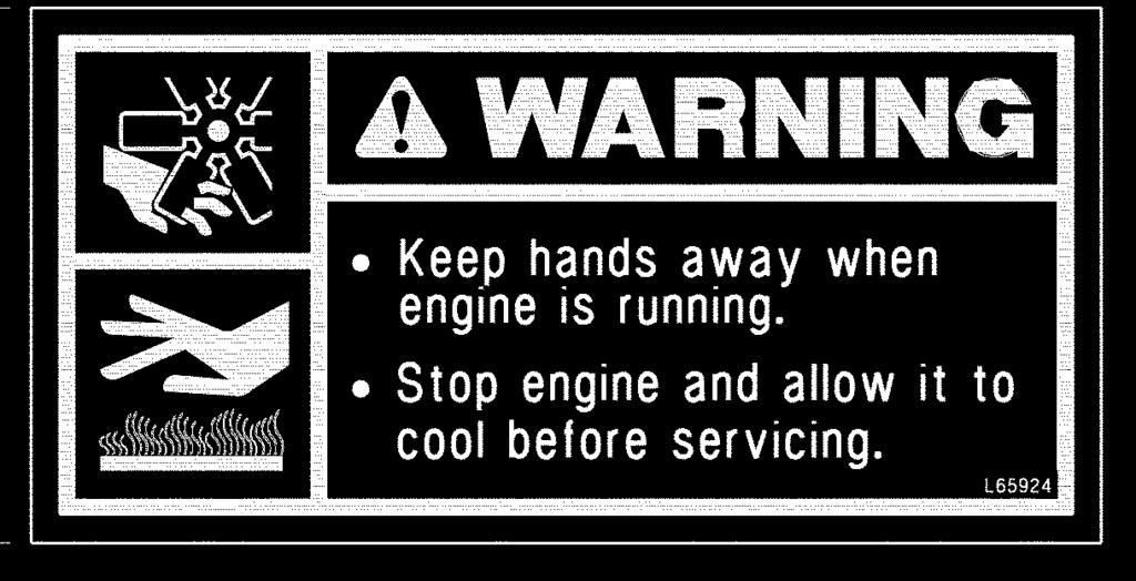
18 Chapter 5 INDICATORS AND CONTROLS CAUTION Become familiar with and know how to use all safety devices and controls on the Paver before operating it. Know how to stop the machine operation before operating it. This Paver is designed and intended to be used ONLY with GEHL Company accessories or GEHL Company approved accessories. GEHL Company cannot be responsible for operator safety if the Paver is used with unapproved accessories or attachments. control and instrument panel electrical circuits. Also, this is the only position in which the ignition key can be inserted or removed from the key switch. GUARDS AND SHIELDS Whenever possible and without affecting Paver operation, guards and shields are used to protect potentially hazardous areas. In many places, decals are also provided to warn of potential dangers and to display special operating procedures. CONTROL INDICATORS AND SWITCHES (Figures 1-4) The control panel on the backwall console area contains the following indicators and switches: Ignition Keyswitch WARNING Read and thoroughly understand all safety decals on the Paver before operating it. Do not operate the machine unless all factoryinstalled guards and shields are properly secured in place. OFF Position: When the key is vertical in the key switch, power from the battery is disconnected to the Figure 1 RUN Position: When the key is turned one position clockwise from the vertical (OFF) position, power from the battery is supplied to all control and instrument panel electrical circuits. START Position: Turn the key clockwise two positions from the vertical (OFF) position to activate the engine starter. The key will return to the RUN position automatically as soon as the engine starts. NOTE: The key must always be returned to the OFF position between starting attempts. The battery charge and engine oil pressure indicators should activate when the key is turned to the RUN position. Pre-Heat Glow Plug Indicator: As an engine starting aid, pre-heating is required in a cold engine starting condition. This pre-heating uses a pre-heater coil that is activated by rotating the key counterclockwise to the pre-heat position. Engine Throttle: This controls the engine speed. Idle position is with the cable fully in. Operating position is with the cable 1 to 1-1/2 inches out. Release the lock ring, depress the red button on the knob and pull the /AP PRINTED IN U.S.A.


19 Figure Figure 3 1. Ignition Keyswitch 2. Pre-heat Glow Plug Indicator 3. Engine Throttle Control 4. Horn Button 5. Battery Charge Gauge 6. Engine Coolant Temperature Gauge 7. Engine Oil Pressure Indicator 8. Hourmeter 9. Washdown Sprayer Switch 10. Fuel Level Gauge 11. Hydraulic Pump Variable-Speed Lever 12. Track Travel Levers 13. Modular Steering Control 14. Hydraulic Fluid Reservoir 15. Paving Alignment Guide 16. Releasing Agent Filler Cap 17. Engine Fuel Filler Cap 14 Figure 4 15 PRINTED IN U.S.A /AP0206
20 knob out to set speed. Rotate the knob left or right to fine adjust the speed during operation. Horn Buttons: The horn may be activated from pushbuttons on the left and right sides of the console. Fuel Level Gauge: Indicates the amount of fuel remaining in the fuel tank. Battery Charge Gauge: Indicates the condition of the charging system. During normal operation, this indicator should register a charge of volts. Coolant Temperature Gauge: Indicates engine coolant temperature. Under normal operating conditions, this gauge should indicate approximately 185 o F o F (85 o C - 88 o C). Engine Oil Pressure: This lamp indicates whether sufficient engine lubricating oil pressure is present. During normal operation, with the engine running, this lamp should be OFF. During starting and when the engine is not running, this lamp will be ON. IMPORTANT: If this lamp comes ON during normal operation with the engine running, STOP the engine immediately. After allowing the oil to drain down for a few minutes, check the engine oil level. Maintain oil level at the FULL mark on the dipstick. Hourmeter: Indicates the operating time of the machine and should be used for keeping up the maintenance log chapter of this manual. Washdown Sprayer System: Sprayer is used periodically each day to wash down parts of the Paver with an asphalt releasing agent. WARNING Do not spray releasing agent on a hot engine. Do not spray releasing agent while the screed propane heaters are in use. Hydraulic Fluid Reservoir: The access/fill plug on top may be removed to check fluid level. NOTE: Before removing the access/fill plug, allow the fluid to cool for minutes. Take a wrench and slowly loosen the hydraulic breather cap on the backwall top console to release system pressure. Paving Alignment Guide: This is adjustable so the chain will align with a curb or the edge of a previously laid mat of asphalt. TRAVEL CONTROLS (Figures 6-7) These controls are used to maneuver the Paver around on the jobsite or for road travel. Decals on the backwall top console area provide graphic representation of the various control actions. Hydraulic Pump Variable Speed: This lever increases or decreases oil flow to the drive motors. Push the lever forward to increase speed; pull rearward to decrease speed. Place the lever in neutral when not operating to prevent creating excess heat in the hydraulic system. NOTE: Lever must be in neutral position to start the engine. Track Travel: These two levers control the track drive motors for forward and rearward movement and also turning of the Paver. Both levers are mechanically linked to levers on the right side of the Paver for control from either side. NOTE: Right and left are determined from a position standing behind the unit and facing the direction of forward travel. Pivot the machine at slow speeds only. Movement of the travel levers and the expected results are as follows (see Figure 5.): Move both levers forward to go forward. Move both levers rearward to go backward. Move the left track lever forward to pivot-turn right. Move the left track lever rearward to pivot-turn left. Move the right track lever forward to pivot-turn left. Move the right track lever rearward to pivot-turn right. Move both levers in opposite directions to spin the machine about its center position. Returning both levers to neutral position stops the drive tracks /AP PRINTED IN U.S.A.
.")

 Hopper Floor: Move lever rearward to raise hopper.")

21 Figure 6 6 Figure 5 - Track Travel Action Modular Steering Control: This control is used for making small steering adjustments. It will be necessary to adjust this valve as paving conditions vary (see Figure 2). With the track travel levers both either forward or rearward, set the pump speed lever to the desired position. Turn the modular steering control counter-clockwise to turn left and clockwise to turn right. Place the control in the center position to move straight ahead Figure 7 1. Left Track Travel 2. Right Track Travel 3. Hopper Floor 4. Right Flow Gate 5. Left Flow Gate 6. Side Gate Valve (1 on each side of machine) 7. Right Feed Auger 8. Left Feed Auger 9. Screed Lift 10. Screed Vibrator 11. Right Screed Extension 12. Left Screed Extension HOPPER CONTROLS (Figures 6-7) Hopper Floor: Move lever rearward to raise hopper. Move lever forward to lower hopper. This lever is mechanically linked to a dual control lever on the right side. Right and Left Flow Gates: These control flow of asphalt out of the hopper. One lever controls each gate. Move lever rearward to open gate. Move lever forward to close gate. Side Gates: When paving only eight feet wide, the side gates should be closed. This is achieved by closing the shut off gates with the side gate valve ON, then turning the side gate valve to the OFF position before re-opening the shut-off gate. PRINTED IN U.S.A /AP0206


22 Right and Left Feed Augers: These are used intermittently only with screed extensions out. One lever controls each auger. Move lever rearward to turn on auger. Return lever to neutral to turn off auger. The right auger lever is mechanically linked to a dual control lever on the right side. SCREED PLATFORM CONTROLS (Figures 6-9) Up and Down Position: Move the lever rearward to lower screed so that it floats over asphalt feed, forming the finished mat surface. Move the lever forward to raise screed off mat. thickness must be measured with a depth gauge. Side Shoe Plate: Loosen wing nuts for adjustment and re-tighten. Screed Extension Adjustment: Use this adjustment to apply the same amount of compaction on the rear edge of the extension as the main screed, for a smooth mat transition from the extension to the main screed. Turning the adjustment screw counter-clockwise will move the rear edge of the extension down. Vibrator: This is used to assist in compacting the mat of asphalt passing under the screed. Move the lever rearward to turn the vibrator on. Allow the lever to return to neutral to turn off the vibrator. Left and Right Extensions: These allow adjusting the paving width beyond eight feet. One lever controls each extension. Move the lever forward to shift the extension inward. Move the lever rearward to shift the extension outward. The right extension lever is mechanically linked to dual control levers on both sides of the machine Figure 9 1. Turnbuckle Ratchet Handle 2. Turnbuckles 2 3 Figure 8 1. Screed Depth Adjustment 2. Depth Indicator 3. Side Shoe Adjusting Nuts 4. Screed Extension Adjustment Screed Depth Adjustment: The screed has manually operated adjustment screws on each end of the screed that are used to set the thickness of the asphalt mat. Turn the screws clockwise to increase the depth; turn the screws counter-clockwise to decrease the depth. A indicator on each adjustment screw can be used as a reference for the desired mat thickness. Actual mat Crown Adjustment: This is made by adjusting the turnbuckles at the center of the screed. The turnbuckles are connected together by means of a chain between them. Use the attached rachet type handle to turn the turnbuckle ends outward, to increase the mat crown. Turning the turnbuckles the opposite way will turn the turnbuckle ends inward to decrease the mat crown, or invert the screed to pave a valley. Propane Heated Screed: The 1648 Paver is equipped with a dual-burner propane-fueled screed heater. Two burners are located in the center of the screed for even heating across the bottom of the screed and the extensions. Pre-Lighting Instructions (see figure 10): 1. Check that all fittings are tight and hoses are in good condition. 2. Check for leaks by closing valves 1, 3 and Open valve 1 on the propane tank /AP PRINTED IN U.S.A.

 Lighting Instructions (see figures 10 and 11): 1. Check that the extensions are either fully extended or fully retracted.")

23 4. If you smell propane, there is a leak. Check for leaks by spraying a mixture of water and liquid soap on the fitting joints and hoses. When theleak is located, close the tank valve and repair the leak Figure 10 Figure 11 Shutting Off the Burners: 1. Main Valve 2. Pressure Regulator Valve with Gauge 1. Close the main valve (1) on the tank. 3. Burner with Valve 2. Close the pressure regulator valve (2). 4. Ignitor with Valve 5. Burner Ignition Hole 3. Close the burner valves (3) Lighting Instructions (see figures 10 and 11): 1. Check that the extensions are either fully extended or fully retracted. The extensions will heat better if they are fully extended. 2. Open valve (4) on ignitor. 3. Open main valve (1) on the tank. 4. Adjust pressure regulator valve (2) to 5 psi. 5. Light the ignitor using a striker or similar lighter. 6. With lighted ignitor in the burner ignition hole, open the burner valve to light the burner. Repeat this procedure for the other burner. 7. After both burners are lit, adjust the pressure regulator valve (2) until it reads psi. 8. The screed should be sufficiently heated after minutes. Overheating the screed can cause the screed to warp. PRINTED IN U.S.A /AP0206
24 Chapter 6 OPERATION AND ADJUSTMENTS GENERAL INFORMATION ENGINE BREAK-IN CAUTION BEFORE starting the engine and operating the Paver, review and comply with all safety recommendations in the SAFETY chapter of this manual. Know how to stop the Paver before starting it. The engine does not require extensive break-in. However, for the first 100 hours of operation: Allow the engine to idle for a few minutes after every cold start. Do not idle the engine for long periods of time. Do not operate the engine at maximum power for long periods of time. Check the oil level frequently and replenish as necessary. A special break-in oil is not used. The oil in the engine crankcase is the same specified for regular oil changes. Change the oil and replace the oil filter at the intervals specified in the SERVICE AND STORAGE chapter. Do not add special additives or special breakin components to the crankcase. BEFORE STARTING ENGINE Before starting the engine and running the Paver, refer to the INDICATORS AND CONTROLS chapter and familiarize yourself with the various operating controls, indicators and safety features. STARTING THE ENGINE BEFORE mounting the screed platform, walk completely around the machine to make sure no one is, on, or close to it. Let others near the area know you are going to start up and wait until everyone is clear of the machine. Place all hydraulic function controls and the hydraulic pump speed control lever in neutral position. The following procedure is recommended for starting the engine: 1. Set the throttle control to 1/3 open. 2. Turn the key to the START position. When the engine starts, release the keyswitch and it will automatically return to the RUN position. 3. In cold weather starting, first turn the key counterclockwise to activate glow plug. When the indicator lamp comes on, proceed as in Step 2. IMPORTANT: Crank the starter until the engine is started. If the engine fails to start within 15 seconds, return the key to the OFF position, wait 2 minutes, and try to restart the engine. Cranking the engine for longer than 15 seconds will result in premature failure of the starter. After the above steps proceed as follows: 1. Allow a sufficient engine warm-up time before attempting to operate the controls. 2. Check that indicators are in normal condition. 3. Check the color of the exhaust gas. It should be light blue or colorless. 4. Check that there are no fuel, oil or engine coolant leaks, and no abnormal noises or vibrations. If the battery becomes discharged and fails to have sufficient power to start the engine, jumper cables can be used to obtain starting assistance. Refer to the jump starting instructions in the SERVICE AND STORAGE chapter of this manual for safe jump-starting procedure. CAUTION Be sure the area being used for test-running is clear of spectators and obstructions. For the first time, operate the Paver with an empty hopper /AP PRINTED IN U.S.A.
25 FIRST TIME OPERATION Be sure the engine is warm and then go through the following procedures: Familiarize yourself with various control levers. Raise the screed. Control the Paver travel forward and backward, then make left and right turns using the track control levers and modular steering control. While stopped, lower the screed and activate the vibrator. Position the side gates and extensions in and out. Raise and lower the hopper and turn the auger motors on and off. STOPPING THE PAVER The following procedure is the recommended sequence for stopping the machine: 1. Place pump variable speed lever in neutral. 2. Place both track control levers in neutral. 3. Lower the hopper and screed to full down positions. 4. Place all function control levers in neutral. 5. Move the throttle to idle position. 6. Turn the keyswitch to off position. Always remove the key and take it with you for security reasons. GENERAL PAVER OPERATION Walk-around Inspection 1. Inspect suction hose. Should be firm, not soft. 2. Check for hydraulic leaks. 3. Check hopper sides and floor clearance. 4. Inspect the screed. 5. Check that safety guards and covers are in proper place. Hands-On Check 1. Check the fuel gauge. Fill the tank before paving and as necessary. 2. Check the engine oil level and replenish as necessary. IMPORTANT: Follow the manufacturer s recommendations regarding the use of proper fuel, lubricants and oil. WARNING To prevent a fire or explosion, allow the engine to cool down before refilling the fuel tank. A hot engine could ignite spilled fuel and burn you. Also, do not smoke while refilling the fuel tank. 3. Check the cooling air intake on the radiator. 4. Check the air cleaner for cleanliness and make sure that components are tight to prevent intake of unfiltered air. 5. Check the hourmeter against fuel filter change schedule in the maintenace log of this manual. 6. Check the pump speed control lever for full travel movement. WARNING Clean external surface of tracks with asphalt releasing agent, using the washdown sprayer. Do not spray releasing agent into tracks immediately before loading or unloading. Wet tracks can slip and lose traction. 7. Clean external area of both tracks (clean three to four times during working day). 8. Check for and remove as necessary, any asphalt buildup in the screed platform propane burner area and the exhaust ports located on each end of the screed. 9. Check for, and remove as necessary, any asphalt buildup inside the tracks. 10. Make a general inspection of the machine for loose bolts and components. 11. Be sure safety guards and covers are in place. WARNING NEVER operate the Paver with safety guards or covers removed. If the Paver is found to be in need of repair or in any way unsafe, or contributes to an unsafe condition, the matter MUST be reported immediately to the user s PRINTED IN U.S.A /AP0206
26 designated authority. The machine MUST NOT be operated until it has been restored to a safe operating condition. PAVING AT THE JOBSITE The following areas should be sprayed down with asphalt releasing agent (use the washdown hose) before paving and four times or more during the work day. These areas should also be cleaned throughly after each use of the machine: Hopper, augers and underside of the screed. Push rollers. Hydraulic fluid reservoir. External track and sprockets. Any part of the machine that contacts asphalt. With the engine warmed up, proceed as follows: Positioning the Paver WARNING Do NOT spray tracks before loading or unloading Paver on a truck or trailer, because this could cause loss of traction. 1. Using the propane burners, heat the screed by following the procedure in the INDICATORS AND CONTROLS chapter. 2. Maneuver the Paver into position for laying asphalt with the track control levers. 3. With Paver in position, move the screed control lever to down and hold until the screed lift cylinder is fully extended. This permits the screed to float free. Screed should be lowered onto a starting pad of asphalt or blocks of the desired paving thickness. 4. Manually adjust the screed depth control screws up or down, as required, to a neutral or free position. Slowly turn the screws toward the up position until a slight amount of tension is felt. The screed is now set to lay asphalt to the approximate thickness of the starting pad or blocks onto which the screed has been lowered. 5. Move the right and left flow gate control levers to the closed position and hold until both gates are fully closed. Set the alignment guide on the left side of the lower front frame. Filling the Hopper 6. Have the dump truck back up to the front of the Paver until the truck tires are one to two inches from the push rollers. Then move the Paver forward until the push rollers contact the rear tires of the truck. DO NOT raise the screed. 7. Move the hopper control lever to the up position and hold until the hopper almost touches the frame or dump body of the truck. 8. Signal the truck driver to slowly raise the dump body, allowing asphalt to flow from the truck into the hopper. Be prepared to lower the hopper to prevent the truck dump body from striking and damaging the hopper as the truck dump body is raised. Fill the hopper with asphalt. 9. Move the flow gate control levers to the open position and hold until flow gates are completely open. Asphalt will then gravity feed down to and form a head of asphalt at the leading edge of the screed. 10. If the area to be paved is level and pushing the truck is desired, place the track control levers forward. The engine throttle should be set at full power. Signal the driver to leave the truck in neutral with thedump body raised a sufficient height to allow asphalt to flow slowly but continuously into the hopper. Laying the Asphalt 11. Use the extension control levers to adjust the desired paving width if it is to be more than eight feet. 12. Move the hydraulic pump speed control lever forward to the desired travel speed. Continue forward, laying asphalt and pushing the truck approximately 36 to 48 inches. If vibration is desired on the screed, move the vibrator control lever to on position at approximately the same time the hydraulic pump speed control lever is moved to the forward position. 13. Move the hydraulic pump speed control lever to neutral position, to stop the Paver. ALWAYS move the vibrator control lever to off position /AP PRINTED IN U.S.A.
27 when stopping forward motion of the Paver. It may be necessary to signal the truck driver to stop, if the truck is moving. NOTE: The truck should not be in gear and the truck driver should not ride the brakes. Always advise the truck driver of the procedure for pushing the truck with the Paver. 14. Check thickness/depth of asphalt in the 36 to 48 inch mat and make necessary adjustment using the manual depth adjustment screws. Make adjustments up or down gradually to avoid porpoising effect or ripples in the mat as a result of adjusting too much in either direction. If the base on which the asphalt is being laid is on grade and level, only infrequent adjustments will be required after initial asphalt thickness/depth setting is made. NOTE: Refer to the TROUBLESHOOTING chapter in this manual for Paver-related, or material delivery and compaction-related paving mat application problems. 15. Move the hydraulic pump speed control lever to forward and continue to pave until the truck is empty and the hopper is approximately 50% full. NOTE: Leave a small head of asphalt at the leading edge of the screed while waiting for the next load of asphalt. If the wait is longer than 10 to 15 minutes, pave 12 to 18 inches further and again leave a small head of asphalt. Repeat in 10 to 15 minute intervals using asphalt remaining in the hopper until next load arrives. If the Paver is to be used by itself, without a dump truck, disregard procedures involving pushing the dump truck for continuous feed while paving (discussed in Steps 10-13) and refer to the following: 16. After the hopper is fully loaded, signal the truck driver to lower the dump body, stopping the flow of asphalt to the Paver. Simultaneously, the Paver operator should move the hopper control lever to the up position raising the hopper to avoid asphalt spills from the front of the hopper. 17. The Paver operator should then signal the truck driver to move forward to the next place to reload the Paver. This next reloading place may be directly in front of the Paver at a point where the Paver operator expects the hopper to be emptied, or another location on the jobsite. PRECAUTIONS WHILE PAVING The right side control levers for auger, extension, track and hopper modes allow a two-person operation to avoid making blind joints and to reduce cycle time when paving in two directions. The screed vibrator should be operated ONLY when the Paver is moving to avoid undue compaction in the mat when the Paver is stopped. DO NOT raise the hopper against the truck frame or the dump body of the truck. When pushing a truck on level ground, the truck should not be in gear and the truck brakes should not be held. The Paver will not push a truck with the brakes on. The two independently-operated augers need only be used when the extensions are out and then only occasionally. The augers are used ONLY for keeping the extended area fully charged with asphalt. NOTE: DO NOT leave the augers operating contiuously unless required! If the hopper is loaded and the operator wishes to close the flow gates to transport material to an area inaccessible to the truck, or reposition the Paver for the next pass, etc., the following procedure should be employed. ALWAYS lower the hopper as low as possible without spilling asphalt. Close one flow gate and then the other. Lowering the hopper substantially decreases the weight being lifted by each flow gate. Make sure screed extensions are also closed. DO NOT pull Paver with another vehicle except in an emergency situation (loss of hydraulic power or engine failure). The track control levers MUST be locked in the float position. Remove the lock lever and place control levers all the way forward. Replace the lock lever. DO NOT pull the Paver backwards! DO NOT pull the Paver at high speeds! When paving uphill, lower the hopper as needed, placing more weight directly over the tracks to increase traction. Handling Asphalt Spills IMPORTANT: ALWAYS remove asphalt spill (large or small) from the path of the Paver tracks to prevent loose asphalt from getting in the tracks, or building up on the sprockets. PRINTED IN U.S.A /AP0206
28 The following procedure should be used if the asphalt truck moves away from the Paver when loading or being pushed, resulting in a large asphalt spill in front of the Paver: 1. Stop the Paver. WARNING Do not attempt to move hot asphalt mix with your hands or feet. Contact can cause serious skin burns! 2. Lower the hopper as low as possible without spilling more asphalt. 3. Close one flow gate and then the other. 4. Windrow spilled asphalt material to the center and in front of the Paver, making sure the asphalt is removed from the path of the Paver tracks. 5. Move the hydraulic pump speed control lever to forward, continuing to pave with asphalt previously gravity fed from the hopper. As the asphalt head from the hopper begins to run thin, the windrow asphalt should be at the leading edge of the screed. If this is the case, continue to pave using the windrow asphalt, opening both flow gates as the windrow of asphalt begins to run thin. If this is not the case, open both flow gates approximately 1/3, maintaining a full head of asphalt at the leading edge of the screed until the leading edge strikes the windrow asphalt. Continue to pave. operation on public highway is prohibited, be sure to transport the Paver using a vehicle of appropriate size and weight. TRANSPORTING BETWEEN JOBSITES (Figures 12-14) When transporting the Paver, know the overall height to allow clearance of obstructions. Remove or tape over the Slow-Moving Vehicle (SMV) emblem if it will be visible to traffic. WARNING Always follow the recommended procedures and guidelines when using ramps to load the Paver onto (or unload it from) a truck or trailer. Failure to heed can result in damage to equipment and serious personal injury or death! Tie-down points are provided on the front of the hydraulic reservoir portion of the frame and the lower rear sides of the backwall. Chains can be inserted through these brackets and slots to secure the Paver while transporting. NOTE: A matched pair of ramps is required. 1. The ramps must be of sufficient strength to support the machine. Whenever possible, the use of strong wood-covered steel ramps is recommended, as well as center supporting blocks. (Figure 12) IMPORTANT: Failure to follow this procedure, in the event of asphalt spills, will result in asphalt buildup and eventual damage to the flow gate cylinders and the tracks. HIGHWAY TRAVEL For short distance highway travel, attach a Slow- Moving Vehicle (SMV) emblem, purchased locally, to the back of the Paver NOTE: Always follow all state and local regulations regarding the operation of equipment on or across public highways! Also, whenever any appreciable distance exists between jobsites or if Figure The ramps must be firmly attached to the truck or trailer bed with no step between the bed and the ramps /AP PRINTED IN U.S.A.
. WARNING NEVER attempt to adjust travel direction (even slightly) while traveling on the ramps.")

29 3. Incline of ramps must be less than 15 degrees (ramp length must be at least 3.9 times height). 4. Ramp width must be at least 1-1/2 times the track width. 5. Block the front and rear of the tires on the truck or trailer (if so equipped, engage the parking brake). WARNING NEVER attempt to adjust travel direction (even slightly) while traveling on the ramps. Instead, back off of the ramps, and re-align the Paver with the ramps. Do not walk beside, behind or in front of the Paver during loading and unloading procedures. ALWAYS place the pump speed control lever in slow position when operating the Paver on the truck or trailer bed. ALWAYS load the Paver in reverse and unload in forward direction. Check for and remove oil, grease, fuel or other substance on the ramps that may cause the tracks to lose traction or slip. Do not wash down the Paver with asphalt releasing agent just before loading or unloading on the vehicle. The Paver tracks may become wet and may slip on the ramps. Paver if travel is not straight. 7. Immediately after the Paver is on the vehicle bed, stop the Paver. 8. Move the pump speed control lever to slow position and reduce the throttle to idle position. 9. Using the track control levers, maneuver the Paver on the trailer or truck for best transporting and balanced position. 10. Rear Loading: After the Paver is on the vehicle bed, place one track lever in forward and one in reverse. The machine will rotate to legal width for transport. 11. Return the screed to flat position by turning the depth adjustment screws in a clockwise direction (seven or eight turns). 12. Lower the screed and place chains in the two tiedown points at the rear of the Paver. Drive the Paver forward allowing chains to tighten slightly (Figure 13). 13. Place a tie-down chain in the tie-down point(s) on the front of the Paver and bind down to the vehicle bed (Figure 13). Loading with Ramps 1. Move the Paver to a position that aligns with the ramps so the Paver will be in position to load in reverse. Stop the Paver Place the throttle control at full open position. 3. Raise the screed to the full up position with the screed control lever. 4. To avoid bumping the rear edge of the screed on the ramps, turn the depth adjustment screws counterclockwise (seven or eight turns).(figure 14) 5. Move the track control levers rearward. 6. Move the pump speed control lever forward, allowing the Paver to move slowly up the ramps. The operator should ride on the Paver with a hand on both track control levers at all times to stop the Figure Rear Tie-down Points (Each Side) 2. Front Tie-down Points Turn the keyswitch to off position and remove the key. PRINTED IN U.S.A /AP0206
 2.")
30 Unloading with Ramps WARNING ALWAYS place the pump speed control lever in slow position when operating the Paver on the truck bed. ALWAYS unload the Paver in forward. Do not walk beside, behind or in front of the Paver during unloading procedures. 1. Remove chain binder from tie-down points on the front of the Paver. (Figure 13) 2. Start the engine according to starting procedure in this manual. 3. With track control levers in reverse position and throttle open about 1/4, place the pump speed control lever in slow. The Paver will move rearward, releasing tension from the two tie-down chains on the rear of the Paver. Stop the Paver. 4. Remove the chains from both tie-down points on the rear of the Paver. (Figure 13) 5. Move the screed control lever to up position and hold until screed is raised completely. 6. To avoid bumping the rear edge of the screed on the bottom of the ramps, turn the depth adjustment screws seven or eight turns counterclockwise. This raises the rear edge of the screed approximately 1 inch. (Figure 14) 7. Using the track control levers, align the Paver tracks with the ramps. When unloading from the rear, rotate and align the Paver tracks. To rotate place one track control lever in forward and the other lever in reverse. 8. Move the Paver forward to the ramps and stop the Paver by placing both track control levers in neutral position. 9. Move the pump speed control lever to slow position. This will prevent the machine from freewheeling down the ramps. 10. The throttle should be set at 1/2 minimum to full open. 11. Clear the area at the bottom of the ramps of all personnel and obstructions. 12. Place both track control levers in forward position, and move the pump speed control lever forward allowing the Paver to travel to the ground. NOTE: The operator should ride on the Paver with one hand on both track control levers at all times, to maintain positive control of the Paver. Emergency stops are accomplished by placing both track control levers in neutral position. In Transit If in transit for a few days: 1.) disconnect the battery, and. 2.) clean all bright surfaces and coat with heavy, very high flash-point grease to prevent rusting. THEFT DETERRENTS Gehl Company has records of component numbers and serial numbers. Users should take as many of the following actions as possible to discourage theft, to aid in the recovery in the event that the machine is stolen, and to reduce vandalism: 1. Remove keys from unattended machines. 2. Attach, secure, and lock all anti-vandalism and anti-theft devices on the machine. ADJUSTMENT SCREW Figure /AP PRINTED IN U.S.A.
31 3. Inspect the gates and fences of the vehicle storage yard. If possible, keep machines in well-lighted areas. Ask the local law enforcement agency to make frequent checks around the storage or work sites, especially at night, during weekends, and on holidays. 4. Report any theft to your dealer and insurance company. Provide the model and all serial numbers. Request that your dealer forward this same information to Gehl Company. PRINTED IN U.S.A /AP0206
32 Chapter 7 LUBRICATION GENERAL INFORMATION WARNING NEVER lubricate or service this unit when any part of the machine is in motion. ALWAYS exercise the MANDATORY SAFETY SHUT- DOWN PROCEDURE (page 10) before lubricating or servicing this equipment. Hydraulic System Reservoir Use SUNVIS 846, or equivalent which contains anti-rust, anti-foam and antioxidation additives and conforms to ISO VG46. Capacity: 20 Gallons (75.7 Liters) All Grease Fittings Use No. 2 Lithium-based Grease Engine Crankcase Oil NOTE: The MAINTENANCE chapter in this manual has provisions for recording the dates and hourmeter readings after lubrication or other service has been performed; use those spaces to keep a log for maintaining a current service interval record. Proper routine lubrication is an important factor in preventing excessive part wear and early failure. LUBRICANTS The following chart lists the locations, temperature ranges and types of recommended lubricants to be used when servicing this machine. Also refer to the separate engine manual (provided) for additional information regarding recommended engine lubricants, quantities required and grades. NOTE: Refer to Operator Services topic in SERVICE AND STORAGE chapter of this manual for detailed information regarding periodic checking and replenishing of lubricants. GREASING AND LUBRICATION Ambient Temperature Grade* Below 32 F (0 C) SAE 10 or 10W F (0-25 C) SAE 30 or 10W-30 Above 77 F (25 C) SAE 40 or 20W-40 *Service Classification: API - CC or CD Capacity: 6.9 Quarts (6.5 Liters) - Diesel Engine Torque Hubs Gear Oil Use API-GL-5 80W-90 Capacity (each hub): 17 ounces (500 cc) IMPORTANT: Always dispose of waste lubricating oils, anti-freeze and hydraulic fluids according to local regulations or take them to a recycling center for disposal. DO NOT pour them onto the ground or into a drain. Refer to the following pages for locations and greasing frequencies. Wipe dirt from the grease fittings before greasing them to prevent contamination. Replace any missing or damaged fittings. To minimize dirt buildup, avoid excessive greasing /AP PRINTED IN U.S.A.
: 1. Grease Depth Adjustment Screws (1 per Screw) 2.")


33 GREASE FITTING LOCATIONS NOTE: See the the SERVICE AND STORAGE chapter of this manual for further details. Every 50 Hours (or weekly): 1. Grease Depth Adjustment Screws (1 per Screw) 2. Grease Track Adjuster Yoke (8 per Track) 3. Grease Pump Speed Control Linkage Replacement Filters Chart Engine Oil Filter Element Gehl P/N P Fuel Filter Element Gehl P/N Hydraulic System Filters Screw-On Filter Element Gehl P/N Reservoir Sump Strainer Gehl P/N Air Cleaner Dry Element Gehl P/N Each Side of Track PRINTED IN U.S.A /AP0206
34 Chapter 8 SERVICE AND STORAGE GENERAL INFORMATION NOTE: All service routines, with the exception of those described under the Dealer Services topic are owner-operator responsibilities. All operator services described under the subtopics are also referred to on a decal which is located on the engine cover. Refer to the LUBRICATION chapter of this manual for lubrication information. NOTE: This SERVICE AND STORAGE chapter details procedures to follow for making routine maintenance checks, adjustments and replacements. Most of the procedures are also referred to in both the TROUBLESHOOTING and MAINTE- NANCE chapters of this manual. For engine-related adjustments and servicing procedures, refer to the engine manual provided. PRECAUTIONS WARNING BEFORE performing any service on the Paver, unless expressly instructed to the contrary, exercise the MANDATORY SAFETY SHUT- DOWN PROCEDURE (SAFETY chapter). After service has been performed, BE SURE to restore all guards, shields and covers to their original positions BEFORE resuming Paver operation. Do not perform any maintenance or repair without the owner s prior authorization. Allow only trained personnel to service the Paver. IMPORTANT: Always dispose of waste lubricating oils, anti-freeze and hydraulic fluids according to local regulations or take them to a recycling center for disposal. DO NOT pour them onto the ground or into a drain. DEALER SERVICES The following areas of internal components service replacement and operating adjustments should only be attempted by (or under the direction of) an authorized GEHL Paver dealer. ENGINE COMPONENTS All service routines, related to the internal components are precise and critical to proper engine operation. Special know-how and tools are required for servicing. NOTE: If the engine is suspected of faulty operation, contact your Gehl dealer for further assistance. HYDRAULIC SYSTEM COMPONENTS Valves, pumps, motors and cylinders are also sophisticated assemblies which require special know-how and tools for servicing. All cylinders are approprietly designed with particular strokes, diameters, checks and hose connection provisions unique to the Paver application requirements. A schematic (located at the end of this chapter) can be used as a guide for troubleshooting and service reference, as required. Internal service on any of these components should only be performed by (or under the direction of) an authorized Gehl Paver dealer. Warranty repairs can only be done by a Gehl dealer. They know what components of the Paver are covered under the terms of the Gehl Warranty and what components are covered by other vendor warranties /AP PRINTED IN U.S.A.
35 ELECTRICAL COMPONENTS An electrical system diagram is provided which includes instrumentation, electrical components and switch connections. The schematic (located at the end of this chapter) can be used as a guide for troubleshooting and service reference, as required. OPERATOR SERVICES Some of the operator related services will require access to components located inside the superstructure under shields, hoods and covers. Choose a clean, level work area. Make sure you have sufficient room, clearances, and adequate ventilation. Clean the walking and working surfaces. Remove oil, grease and water to eliminate slippery areas. Utilize sand or oil-absorbing compound, as necessary, while servicing the Paver. Before starting inspection and repair, move the Paver onto a level surface, shut down engine, and release all hydraulic pressure. Always lower the hopper to full down position. If the area under the hopper requires service, raise the hopper to full up and swing up the two safety props. Place all controls in neutral. Disconnect the battery and remove the ignition key. Remove only guards or covers that provide needed access. Wipe away excess grease and oil. Excessively worn or damaged parts can fail and cause injury or death. Replace any cracked or damaged part. Care should be taken to assure that all replacement parts are interchangeable with original parts and of equal quality. Use care not to damage machined and polished surfaces. Clean or replace all damaged or painted over plates and decals that can not be read. NOTE: Never leave guards or access covers off when the Paver is unattended. Keep bystanders away if access covers are removed. After servicing, check the work performed, no parts left over, etc. Install all guards, covers and reconnect the battery. WARNING Do not smoke or allow any open flames in the area while checking or servicing hydraulic, battery or fuel systems; all contain highly flammable liquids or explosive gases, which can cause an explosion or fire if ignited. Wear a face shield when you disassemble spring-loaded components or work with battery acid. Wear a helmet or goggles with special lenses when you weld or cut with a torch. When working beneath a raised machine, always use blocks, jack-stands or other rigid and stable supports. Wear appropriate protective clothing, gloves, shoes. Keep feet, clothing, hands and hair away from moving parts. Always wear safety glasses or goggles for eye protection from electric arcs from shorts, fluids under pressure, and flying debris or loose material when the engine is running or tools are used for grinding or pounding. NEVER weld on hopper, screed or frame without the consent of the manufacturer. Special metals may be used, which require special welding techniques or have a design that should not have weld repairs. NEVER cut or weld on fuel lines or tanks. If repair welding is ever required, be sure to attach the ground (-) cable from the welder as close as possible to the area to be repaired. Also, remove battery positive (+) terminal connection before proceeding to weld. Service Every 10 Hours or Daily SPRAY DOWN ASPHALT CONTACT AREAS The following areas should be sprayed with asphalt releasing agent before paving, at least four times during operation, and after each use of the Paver. 1. Hopper and Augers 2. Screed (bottom) 3. Push Roller Assembly 4. Hydraulic Fluid Reservoir 5. Drive tracks PRINTED IN U.S.A /AP0206
36 6. Any other part of the machine which contacts asphalt WARNING Do not spray releasing agent into tracks before loading or unloading the Paver on a truck or trailer, because this could cause loss of traction. Do not spray releasing agent on a HOT engine. Do not spray releasing agent while the screed propane heaters are in use. CHECK FUEL TANK LEVEL After operation each day, the fuel tank should be filled to prevent water from condensing in the tank. To fill, remove the filler cap and add fuel. A drain plug is provided in the bottom of the tank for removing condensation and other foreign materials periodically. Open the plug and allow water and fuel to drain into a container until only clear fuel is flowing from the tank. IMPORTANT: DO NOT discharge fuel onto ground. Catch and dispose of per local waste disposal regulations. CHECK ENGINE OIL LEVEL With the Paver on level ground, and the engine stopped for ten minutes or more, remove the engine dipstick. Wipe it clean, re-insert it and remove to obtain a reading. If the oil level is down, or below the ADD mark, fill with the required amount of oil to bring the level to the FULL mark. See the LUBRICATION chapter for the type of oil to use. CHECK RADIATOR COOLANT LEVEL WARNING DO NOT remove the radiator cap when the engine is running hot or overheated. Coolant is extremely hot and under pressure and it can burn your skin. Allow sufficient time for the radiator to cool before relieving the pressure and removing the radiator cap. With the Paver on level ground, remove the radiator cap. Add clean engine coolant mixture of 50/50 water and anti-freeze if the coolant level is below the filler neck. Replace the radiator cap securely. NOTE: If the engine is operated with a loose or damaged radiator cap, the pressure bypass will not work and the engine will run hot. CHECK INSTRUMENTS OPERATION Allow the engine to warm up for about five minutes before beginning operation. Indicator lamps should not be lit and gauges should register normal readings. CHECK GENERAL MACHINE OPERATION AND CONDITION Are any decals missing or damaged? Are all guards, shields and covers in place? Do all controls function smoothly and properly? Are there any abnormal vibrations or noises? Are any hoses or fitting connections leaking? Is the engine exhaust color normal (light blue or colorless)? Every 50 Hours or Weekly The following service checks should be done at the beginning of each working week and in full conjunction with Daily Service. CHECK FAN BELT If the belt shows wear or cuts, it should be replaced. Order replacement belt from your engine dealer. Refer to the engine manual relative to proper belt replacement and tension adjustment procedures. CHECK FUEL FILTER NOTE: The fuel filter will require occasional replacement to maintain a clean and adequate fuel flow for maximum engine horsepower. The frequency of filter replacement will be determined by the cleanliness of available fuel, the care used in storing fuel supplies and the operating conditions in which the Paver is used. Small amounts of water can be drained from the engine fuel filter. The drain petcock should be loosened weekly to drain off water accumulation until clear fuel is flowing from the outlet. IMPORTANT: DO NOT discharge fuel onto ground. Catch and dispose of per local waste disposal regulations /AP PRINTED IN U.S.A.
37 CHECK HYDRAULIC OIL LEVEL The fluid must be cool when checking the reservoir level, or changing the filter. By doing this, you will reduce the possiblity of overfilling the hydraulic system, and also reduce potential injury due to hot fluid. Before removing the fill plug, release pressure in the hydraulic system by allowing pressure to bleed-off when loosening the fill plug. This can also be done by loosening the breather cap on top of the backwall console. NOTE: Be careful when removing the reservoir filler cap so that no dirt or other foreign matter enters the hydraulic system while the cap is removed. DO NOT OVERFILL. See the LUBRICATION chapter of this manual for recommended hydraulic oils. CHECK BATTERY FLUID AND CABLES Check cables for corrosion or loose connection. Check to see if fluid level is full in each cell. NOTE: The battery on the Paver is warranted by the supplier. See the punch tag on the top of the battery for warranty information. Handling Battery Safely WARNING ALWAYS protect face and eyes whenever a pressure plug or cap is removed. NEVER assume that no pressure exists in a pressure vessel or system. The top of the battery must always be kept clean. Clean the battery with a brush dipped in an alkaline solution (ammonia or baking soda and water). After the foaming has stopped, flush the top of the battery with clean water. If the terminals and cable connection clamps are corroded or have a buildup, disconnect the cables and clean the terminals and clamps with the same alkaline solution. Jump-starting WARNING Explosive gas is produced while a battery is in use or being charged. Keep flames or sparks away from the battery area. Be sure battery is charged in a well-ventilated area. NEVER lay a metal object on top of a battery as a short circuit can result. Battery acid is harmful on contact with skin or fabrics. If acid spills, follow these first aid tips: 1. IMMEDIATELY remove any clothing on which acid spills. 2. If acid contacts the skin, rinse the affected area with running water for 10 to 15 minutes. 3. If acid comes in contact with the eyes, flood the eyes with running water for 10 to 15 minutes. See a doctor at once. NEVER use any medication or eye drops unless prescribed by the doctor. 4. To neutralize acid spilled on the floor, use one of the following mixtures: a. 1 pound (0.5 kg) of baking soda in 1 U.S. gallon (4 liters) of water. b. 1 pint (0.5 liters) of household ammonia in 1 U.S. gallon (4 liters) of water. Whenever battery is removed from the unit, BE SURE to disconnect the negative (-) battery terminal connection cable first. If the Paver battery becomes discharged or does not have enough power to start the engine, use jumper cables and the following procedure to jump-start the Paver engine. IMPORTANT: BE SURE that the jumper battery is also a 12-volt D. C. battery and the vehicle used for jump starting has a negative-ground electrical system. PRINTED IN U.S.A /AP0206
38 WARNING The ONLY safe method for jump-starting a discharged battery is for TWO PEOPLE to perform the following procedure. The second person is needed for removing the jumper cables so that the operator does not have to leave the operator s position while the engine is running. NEVER make the jumper cable connections directly to the starter solenoid of either engine. DO NOT start the engine from any position other than the operator s position, and then ONLY after being sure all controls are in neutral. Closely follow the jump-start procedures, in the order listed, to avoid personal injury. In addition, wear safety glasses to protect your eyes and avoid leaning over the batteries while jump-starting. DO NOT attempt to jump-start the Paver if the battery is frozen, because this may cause it to rupture or explode. 1. Turn the keyswitches on both vehicles to OFF. Be sure that both vehicles are in neutral and not touching. 2. Connect one end of the positive (+) jumper cable to the positive (+) battery terminal on the disabled vehicle first. Do NOT allow the jumper s positive (+) cable clamps to touch any metal other than the positive (+) battery terminals. Connect the other end of the positive jumper cable to the jumper battery positive (+) terminal. 3. Connect one end of the negative (-) jumper cable to the jumper battery negative (-) terminal. 4. Make the final negative (-) jumper cable connection to the disabled Paver s engine block or frame (ground) NOT to the disabled battery negative post. If making the connection to the engine, keep the jumper clamp away from the battery, fuel lines, and moving parts. NOTE: Twist the jumper cable clamps on the battery terminals to ensure a good electrical connection. 5. Proceed to start the Paver. If it does not start immediately, start the jumper vehicle engine to avoid excessive drain on the booster battery. 6. After the Paver is started and running smoothly, have the second person remove the jumper cables (negative (-) jumper cable, first) from the jumper vehicle battery, and then from the disabled Paver, while ensuring not to short the two cables together. Allow sufficient time for the Paver alternator to buildup a charge in the battery before operating the machine or shutting off the engine. NOTE: If the battery frequently becomes discharged, have the battery checked for possible dead cell(s) or troubleshoot the entire electrical system for possible short circuits or damaged wire insulation. CHECK/CHANGE AIR CLEANER ELEMENT (Figure 15) Completely wipe the outside of the air cleaner body with a rag or cloth. Blow off excess dirt and dust with compressed air. Dissassemble as follows: 1. Loosen the clamp ring and remove the end cap. Remove the baffle. Wipe the end cap and baffle completely clean. Reassemble the end cap. 2. Remove the element wing nut and the element. Wipe the entire inside of the main body and inlet cap screen. 3. Inspect the element for clogging or holes. If the element is clogged or damaged it should be replaced. IMPORTANT: NEVER use an element that is damaged. Severe engine wear and eventual failure can result if dirt gets through a hole in the element. Make sure the clean element has no holes or ruptures. Placing a bright light inside the element and inspecting the outside will show up any holes or tears. Discard the element if holes or tears are evident. Install the element and reassemble the air cleaner /AP PRINTED IN U.S.A.
39 5 1 WARNING Hydraulic fluid is hot during operation. Allow to cool before relieving system pressure by loosening breather cap on top of the backwall. Figure 15 - Air Cleaner Components 1. Body 2. Inlet Cap 3. Dust Cup and Clamp Ring 4. Mounting Band 5. Element 2 1 LUBRICATE GREASE POINTS Refer to the LUBRICATION chapter of this manual for fitting locations and other related details. 50 Hours (New Machine Only) Figure 16 - Hydraulic Filter Components The following initial oil and filter changes should be made at this time on a new machine. Thereafter these changes should be made at the regular maintenance schedule listed. Refer to those schedules for procedures necessary. Engine Oil and Filter Hydraulic Filter Elements (250/500 Hours) (250 Hours) Service Every 250 Hours Perform all other service requirements up to this point as well as the following: CHANGE HYDRAULIC FILTERS (Figure 16) Remove both elements and discard. Wipe the sealingsurface on the mount head with a clean cloth. Apply a thin coat of clean oil to the new oil filter gasket. Spin tighten. 1. Filter Element 2. Mounting Head (Bottom Side of Top Console) CHECK SCREED BOTTOM PLATE The bottom plate of the screed should be inspected for possible wear. CHANGE ENGINE OIL Change the engine oil and filter using the following procedure: 1. With the engine warm, remove the crankcase drain plug. Some plugs are equipped with a magnet to gather metal particles. Completely clean and flush away all metallic filings from the plug and reinstall it. IMPORTANT: DO NOT discharge oil onto ground. Catch and dispose of per local waste disposal regulations. PRINTED IN U.S.A /AP0206
 Track chain tensioning is accomplished by hydraulic cylinder force being applied to the front track idler hub.")


40 2. After new oil has been added, run the engine at idle speed until the oil pressure lamp is OFF. Check for leaks at the drain plug. Re-tighten only as much as necessary to eliminate leakage. TRACK HYDRAULIC PRESSURE ADJUSTMENT (Figure 17) Track chain tensioning is accomplished by hydraulic cylinder force being applied to the front track idler hub. Proper tension is achieved by applying 250 psi (17 bar) to 300 psi (20 bar) to the hydraulic cylinder. An adjustable relief valve located on the backwall just behind the screed lift cylinder is used to set this pressure. If the tracks are not adjusting correctly, it may be necessary to check this pressure. Install a PSI (0-35 bar) gauge onto the test port located on the top of the backwall. This relief valve connects hydraulically on the return side of the 7-stack main valve. Increase the pressure as follows: 1 3. The engine must be running and at minimum 1/2 throttle. 4. When pressure is corrected, tighten jam nut, replace cap and remove gauge from test port. NOTE: Track tension will not adjust if engine is not running. CHECK TORQUE HUBS OIL LEVEL Position the track so that one plug is in the 3- or 9- o clock position and the other plug is in the 12-o clock position. Remove the check plug. If oil appears, replace the plug as the level is sufficient. If oil does not appear, remove the fill plug and add oil until it flows from the check plug. Replace both plugs. Repeat for the other track. Service Every 500 Hours FILL PLUG CHECK PLUG Perform all other service requirements up to this point as well as the following: CHANGE ENGINE OIL FILTER (Figure 18) 2 The engine oil filter should be changed at every other oil change interval. Remove and discard the throw away filter canister. Wipe the gasket and sealing area of the block with a clean cloth. NOTE: Use only genuine OEM engine replacement filters. Figure Relief Valve 2. Test Port 1. Remove the cap from the relief valve and loosen the jam nut. 2. Increase the pressure by turning the Allen screw clockwise. Apply a thin coat of clean oil to the new oil filter gasket. Turn new filter on until its gasket contacts the engine sealing surface, then using a filter wrench, tighten the filter another 3/4 turn. Refill the crankcase with new oil. Follow specifications in the LUBRICA- TION chapter for type and viscosity of new oil. CHANGE FUEL FILTER (Figure 18) The cleanliness of available fuel, the care used in storing fuel supplies and the operating conditions in which the Paver is used may require the fuel filter to be changed prior to scheduled intervals /AP PRINTED IN U.S.A.

41 The engine has a screw-on canister filter and a remote fuel pump mounted on the engine. Unscrew the canister element and replace with a new one. Lightly oil the rubber gasket on the top of the filter before installing. Turn the replacement filter until it contacts the sealing surface, then turn 2/3 turn with a filter wrench. NOTE: Fuel will flow from the filter head when the element is removed. To minimize fuel loss, have the replacement element ready for replacement or pinch the fuel hose leading to the filter head prior to removing the filter element. Catch and dispose of spilled fuel per local waste disposal regulations. 6 3 top of the filter head. When fuel flows from the screw, tighten the screw. Turn the keyswitch to the on position for 15 seconds before starting the engine. Start the engine and check the fuel system for fuel leaks. If the engine will not start, consult your authorized engine dealer. WARNING Escaping diesel fuel under pressure can have sufficient force to penetrate the skin. Before applying pressure to the fuel system, be sure all connections are tight and lines and hoses are not damaged. Use a piece of wood or cardboard to search for suspected leaks. If injured by escaping fuel, see a doctor familiar with this type of injury immediately or gangrene may result Hours or Every Season Perform all other service requirements up to this point as well as the following: CHANGE RADIATOR COOLANT Drain, flush and refill the cooling system as follows: 1 2 Figure Fuel Filter 4. Fuel Pump 2. Engine Oil Filter 5. Engine Oil Filler 3. Engine Oil Dipstick 6. Air Filter Fuel Bleeding Procedures When the fuel filter is removed and replaced, air must be bled from the filter. Loosen the bleeder screw on the 4 WARNING NEVER service the fuel system while smoking, while near an open flame, or when the engine is hot Loosen the radiator cap to its stop. This will release any system pressure. Remove the cap when all pressure is bled off. WARNING Remove the radiator cap only when the engine is cool, or painful burns could result. 2. Open the radiator drain cock. Remove the water jacket drain plug from the engine block. When all coolant is drained, flush the system with clean fresh water. Allow the water to drain completely. IMPORTANT: DO NOT discharge onto ground. Catch and dispose of per local waste disposal regulations. PRINTED IN U.S.A /AP0206
42 3. Replace all drain plugs and tighten the radiator drain cock. Clean out the cooling fins in the radiator with water pressure or steam. IMPORTANT: When cold weather is expected, fill the cooling system with a 50-50% mixture of water and ethylene glycol anti-freeze. 4. Inspect the radiator cap seal before installing it. Replace it if it appears defective. The pressure cap and engine thermostat work in conjunction with each other to maintain proper engine cooling. NOTE: Check the coolant temperature gauge, every minute or two after coolant has been changed. Air pockets can form. It may be necessary to refill the cooling system after a short period of use, as the air bleeds out of the system. REPLACE HYDRAULIC OIL AND STRAINER Clean all dirt and debris off the area where the hydraulic system suction (large) hose connects to the inside wall of the hydraulic reservoir. 1. Remove the drain plug from the bottom of the reservoir. Allow all the oil to drain out. IMPORTANT: DO NOT discharge onto ground. Catch and dispose of per local waste disposal regulations. 2. Disconnect the suction hose and remove the sump strainer from inside the reservoir. Inspect the strainer. If it shows any damage, holes, etc. it should be replaced. Otherwise wash it clean with an industrial solvent, dry with a rag and coat with fresh hydraulic oil. 3. Flush out the bottom of the reservoir with clean hydraulic oil. Re-install the strainer, drain plug and reconnect the suction hose. 4. Fill the reservoir with fresh hydraulic oil. Follow specifications found in the LUBRICATION chapater of this manual. IMPORTANT: Hydraulic fluid and filters should be replaced any time contamination is detected before the normally scheduled change. CHECK EXHAUST SYSTEM Check the muffler and pipes for holes or loose clamps. Tighten loose clamps and replace the pipes or muffler if they are leaking or have holes. STORAGE If the Paver will not be operated for a long period of time, prepare and store it using the procedures as follows. BEFORE STORAGE Perform the following prior to placing the Paver in storage: 1. Wash off the entire machine. 2. Lubricate all grease points as described in the LUBRICATION chapter of this manual. 3. Change engine oil as outlined in the SERVICE AND STORAGE chapter of this manual. 4. Apply grease to all exposed hydraulic cylinder rod areas. 5. Add stabilizer to fuel per fuel supplier s recommendation. 6. Disconnect the battery cable clamps and cover the battery or remove the battery from the Paver and store it separately. 7. If the ambient temperature (at any time during the storage period) is expected to drop below freezing, make sure the engine coolant is either completely drained from the radiator and engine block or that the amount of anti-freeze in it is adequate to keep the coolant from freezing. Refer to the separate engine manual provided for anti-freeze recommendations and quantities. DURING STORAGE 1. About once each month, connect the battery, and check all fluid levels to make sure they are at the proper level before starting the engine. 2. Start the engine and allow it to run until it warms up and then move the machine a short distance to help re-lubricate the internal parts. Run the engine until the battery has a chance to recharge and then shut it off /AP PRINTED IN U.S.A.
43 NOTE: If it is desired to operate the hydraulic cylinders at this time, be sure to wipe the protective grease (and any adhering dirt) from the cylinder rods prior to starting the engine. After operating, be sure to re-coat the cylinder rods with grease if the Paver is going to be returned to storage. AFTER STORAGE After removing the Paver from storage and before operating it, perform the following: 1. Change engine oil and filter to remove condensation and any other residual contamination. 2. Wipe off grease from cylinder rods. 3. Lubricate all grease fittings. 4. Review and refamiliarize yourself with all safety precautions as outlined in the SAFETY chapter of this manual. 5. Follow the starting and warm-up procedures as outlined in the OPERATION AND ADJUST- MENTS chapter of this manual. PRINTED IN U.S.A /AP0206
44 Hydraulic Schematic A B C D E F G /AP PRINTED IN U.S.A.
45 Hydraulic Schematic A B C D E F G PRINTED IN U.S.A /AP0206
46 Electrical Schematic /AP PRINTED IN U.S.A.
47 NOTES PRINTED IN U.S.A /AP0206
48 Chapter 9 MAINTENANCE This Maintenance Interval Chart was developed to match the SERVICE AND STORAGE chapter of this manual. Detailed information on each Service Procedure may be found in the SERVICE AND STORAGE chapter. A Maintenance Log follows the Maintenance Interval Chart for recording the service procedures performed. NOTE: Recording the 10-Hour (or Daily) service intervals would be impractical and therefore is not recommended. IMPORTANT: Under extreme operating conditions, more frequent service than the recommended intervals may be required. You must decide if your operation requires more frequent service based on your use. MAINTENANCE INTERVAL CHART SERVICE PROCEDURE Every 10 Every 50 First 50 Hours Hours Hours (or Daily (or Weekly) Check Fuel Tank Level Check Engine Oil Check Radiator Coolant Level Check Instruments Operation Clean Areas Contacting Asphalt Check General Machine Operation and Condition Change Engine Oil and Filter Change Hydraulic Filter Elements Check Air Filter Element Check Fuel Filter Check Fan Belt Tension Check Battery and Connections Check Hydraulic Oil Level Lubricate Grease Points /AP PRINTED IN U.S.A.
49 MAINTENANCE INTERVAL CHART (CONT.) SERVICE PROCEDURE Every 250 Every 500 Every Hours Hours 1000 Hours Change Hydraulic Filter Elements Change Engine Oil Check Torque Hubs Oil Level Check Track Adjustment Check Screed Bottom Plate Wear Change Engine Oil Filter Change Fuel Filter Check Radiator Coolant Change Hydraulic Reservoir Oil and Strainer Check Exhaust System MAINTENANCE LOG Date Hours Service Procedure PRINTED IN U.S.A /AP0206
50 MAINTENANCE LOG Date Hours Service Procedure /AP PRINTED IN U.S.A.
51 MAINTENANCE LOG Date Hours Service Procedure PRINTED IN U.S.A /AP0206
52 Chapter 10 TROUBLESHOOTING The following troubleshooting guide lists potential problems, as well as possible causes and remedies, for the Paver. If a problem occurs, don t overlook simple causes. A malfunction could be caused by something as simple as an empty fuel tank. After a mechanical failure has been corrected, be sure to locate the cause of the problem. IMPORTANT: DO NOT attempt to service or repair major components unless authorized to do so by your GEHL dealer. Any unauthorized repair s will void the Warranty. GENERAL PAVER PROBLEMS DURING OPERATION PROBLEM Engine operation erratic Paver difficult to steer (NOTE: Normal lead off to one side may be as much as 1 to 2 ft. in 100 ft. of travel under low or no load conditions.) Soft or uneven terrain may cause lead off, which may be interpreted as steering problems. (Actual operating conditions will cause the lead off to change.) Paver slowing down or excessive power loss (NOTE: Travel speed is FPM.) Hydraulic controls stall too freely or won t operate under a load Screed not hot enough POSSIBLE CAUSE One forward/reverse lever not fully engaged. Linkage for dual controls binding. Tracks not properly aligned. Internal leakage in modular steer valve. Engine not running at rated speed. Failure of hydraulic system component. (filter, motor, pump, etc.) Hydraulic system leaks. Ports at end of screed plugged. Outside air too cold/or windy. REMEDY Refer to engine troubleshooting. Engage lever. Free up linkage. Correct alignment. Replace seals. Disassemble drive valve and clean load checks. Check fuel filter. Refer to hydraulic component(s) troubleshooting. Locate leaks and correct. Repair faulty component. Refer to hydraulic components troubleshooting. Clear ports. Use propane heater on low while paving /AP PRINTED IN U.S.A.
53 PROBLEM PAVER-RELATED MAT PROBLEMS POSSIBLE CAUSE REMEDY Wavy surface (ripples) Wavy surface (long waves) Tearing of mat (full width) Tearing of mat (center streak) Tearing of mat (outside streak) Mat texture not uniform Screed marks Screed not responding to correction Poor pre-compaction Poor longitudinal joint Poor transverse joint 1. Fluctuating head of materials. 2. Finisher speed too fast. 3. Excessive play in screed mechanical connection. 4. Screed riding on lift cylinder. See Causes 1, 3, Overcorrecting thickness control screws. 6. Running hopper empty between loads. 7. Sitting long period between loads. See Causes Screed plates worn or warped. 9. Cold screed. See Causes 8, Too little crown in screed. See Causes 8, Too much lead crown in screed. 12. Screed extensions adjusted incorrectly. See Causes 1, 2, 4, 7-9, 12. See Causes 3. See Causes 2-4. See Causes Screed riding on lift cylinder. 14. Improper joint overlap. See Causes 3, Incorrect nulling of screed. Maintain full head of material. Reduce speed with the fast-slow lever. Replace attaching bolts. Lower cylinder completely. Make more moderate corrections as infrequently as possible. Stop Paver before head of material reaches screed area. Empty hopper completely if waiting period lets asphalt cool. Replace wear plate. Check ports in screed. Increase lead crown. Decrease lead crown. Raise extension leading edge. Lower cylinder completely. Limit overlap to 2 maximum. Increase pitch of screed before starting. PRINTED IN U.S.A /AP0206
54 MATERIAL-DELIVERY, COMPACTION-RELATED MAT PROBLEMS PROBLEM Wavy surface (short waves - ripples) Wavy surface (long waves) Tearing of mat (full width) Mat texture (center or outside streaks) Mat texture (non uniform) Screed marks Screed not responding to correction Auger shadows Poor pre-compaction Poor longitudinal or transverse joint Transvers cracking (checking) POSSIBLE CAUSE 1. Improper base preparation. 2. Improper rolling operation. 3. Improper mix design (aggregate). 4. Improper mix design (asphalt). 5. Mix segregation. 6. Variation of mix temperature. See Causes 1, 5, Trucks bumping finisher. 8. Truck holding brakes. 9. Reversing or turning too fast of rollers. 10. Parking roller on hot mat. See Causes Improper mat thickness. 12. Cold mix temperature. See Causes 12. See Causes 1, 3-6, 11, 12. See Causes 7, 8. See Causes 6, 11, 12. See Causes 3, 4, 5. See Causes 1, 11, 12. See Causes 2, 12. See Causes 1-4, 6 REMEDY Review base installation. Decrease speed. See Asphalt Paving Manual. See Asphalt Paving Manual. Asphalt plant mixing too long. Asphalt plant burners not heating consistantly. Stop truck short of Paver and drive Paver to truck. Driver must apply brakes only enough so that truck stays in Paver. Cycle must be slow but deliberate. Move to cooler surface before parking. Park at 45 o angle. Mat thickness must be twice size of the largest aggregate. Check with asphalt plant for hotter asphalt mix /AP PRINTED IN U.S.A.
55 MATERIAL-DELIVERY, COMPACTION-RELATED MAT PROBLEMS (Continued) PROBLEM Mat shoving under roller Bleeding or fat spots in mat Roller marks Poor mix compaction POSSIBLE CAUSE See Causes 1-4, 6, 9, 13. See Cause 3, 4, 6, 13. See Causes 1, 2, 6, 9, 10. See Causes 1-4, 6, 9, 10, 12, 13. REMEDY PROBLEM DRIVE AND MAIN CONTROL VALVES POSSIBLE CAUSE REMEDY Incapable of maintaining the load Spool sticking or does not move Oil leaking at seals Internal oil leak at the spool. Oil leaking at relief valve port. Load check poppet or seat damaged. (located inside sections). Hydraulic oil contaminated. Valve clogged with dirt. Inside of plunger cap filled with oil. Foreign matter at spool internal stop. Pressure too high. Lever or link bent. Spool bent. Return spring failing. Return spring or cap misaligned. System oil temperature distribution NOT uniform. Paint sticking at seal. Back-pressure in valve. Dirt in seal. Seal plate has loosened. Seal broken or damaged. Replace entire valve housing and spool. Disassemble and clean or replace relief valve. Replace poppet and seat assembly. Drain and replace with fresh oil. Also replace filters. Remove dirt and clean assembly. Replace seal on end of cap. Remove foreign matter or replace entire valve section and spool assembly. Using pressure gauge, readjust pressure. Remove and replace lever or link. Replace entire valve assembly. Replace spring. Loosen, realign and retighten spring or cap. Allow sufficient warm-up for entire system. Remove and clean the seal. Replace hydraulic oil filter. Remove and clean the seal. Replace valve housing as assembly. Remove and replace seal. PRINTED IN U.S.A /AP0206
56 PROBLEM DRIVE AND MAIN CONTROL VALVES (Continued) POSSIBLE CAUSE REMEDY Controls feel heavy Foreign matter in control valve spool. Valve spool sticking. Control linkage lacking lubrication. Clean control valve. Replace entire valve housing. Properly lubricate linkage. PROBLEM HYDRAULIC PUMP AND MOTORS SYSTEM POSSIBLE CAUSE REMEDY System will not operate in either direction 1. Oil supply low. 2. Oil Filters clogged. 3. Oil too heavy. 4. Control linkage misadjusted. 5. Low charge pressure. Check oil level and fill. Replace filter element. Use proper viscosity oil. Check to see if control linkage is binding or unfastened See remedy for Causes 6-9. Pressure should be psi (20-25 bar) System noisy Sluggish response to acceleration or decceleration Oil leaking from pump or motor. 6. Relief valve stuck open. 7. Damaged check valve. 8. Air in system. 9. Loose suction line. 10. Clogged suction filter. 11. Internal pump or motor damage. See Cause 8. See Cause Low charge pressure. 13. Relief valve dirty or damaged. 14. Defective seal. Remove, clean or replace. Dissassemble and check if valve is faulty or damaged. Low oil level in reservoir. Tighten fittings and/or hose. Replace Element. Dissassemble, inspect, repair or replace. Also see remedy for Causes 1-3, 9. See remedy for Causes 6, 7, 9. Remove, clean or replace. Replace seal and/or complete assembly /AP PRINTED IN U.S.A.
57 PROBLEM HYDRAULIC CYLINDERS POSSIBLE CAUSE REMEDY Insufficient cylinder power hydraulic Relief valve pressure setting decreased. Readjust valve pressure setting. Cylinder internal oil leakage. Replace seals. Cylinder piston or seals defective. Replace piston or seals. Control valve internal oil leakage. Replace entire valve housing. Hydraulic cylinder external oil leakage Piston does not move smoothly Cylinder seals defective. Cylinder rod damaged. Oil temperature is abnormally high. Air being taken into system. Seals defective. Replace seals. Replace rod. Lower the oil temperature. Replenish oil and retighten suction connections. Replace seals. PROBLEM Starter will not turn Battery discharges and/or will not recharge Operating horn, etc. does not function Charge indicator does not activate before engine starts ELECTRICAL SYSTEM POSSIBLE CAUSE Keyswitch is in OFF or RUN position. Speed control not in OFF position. Faulty wiring and/or terminations, or fuse open. Faulty starter switch. Battery not adequately charged. Terminal or cables are loose or corroded, battery is defective, and/or alternator defective. Battery electrolyte level low. Alternator defective. Fuse blown. Faulty alternator. Battery is not sufficiently charged. REMEDY Turn keyswitch to START position. Move speed control to OFF position. Troubleshoot circuit and repair. Replace switch. Recharge switch. Clean terminals and cables and retighten or replace battery; have dealer check alternator. Replenish with distilled water. Replace or repair. Check cause; correct and/or replace fuse. Replace alternator. Recharge battery. PRINTED IN U.S.A /AP0206
58 PROBLEM Engine will not turn over Starter motor has insufficient power to turn engine over Engine cranks over but will not start Engine cuts out abruptly Engine runs rough Engine overheats ENGINE POSSIBLE CAUSE Starter motor defective or faulty wiring connections. Battery is run down, starter is defective and/or wiring connections are broken or loose. Fuel tank is empty. Engine crankcase oil is too heavy. Engine is cold. Out of fuel. Fuel filter is clogged and/or air is trapped in the fuel system. Fuel filter is clogged and/or air is trapped in the fuel system. Air cleaner is clogged. Low radiator coolant Radiator clogged. Crankcase oil level too low. Exhaust is restricted. REMEDY Replace motor and/or repair wiring connections. Charge battery, repair/replace starter, and/or tighten connections. Replenish fuel supply. Drain and replace crankcase oil with proper viscosity oil. See Engine Manual. Replenish fuel. Clean or replace fuel filter and/or de-aerate fuel system. Replace fuel filter and/or de-aerate fuel system. Clean or replace element. Replenish coolant Clean debris from radiator. Add oil as required. When engine cools, remove restriction /AP PRINTED IN U.S.A.
59 NOTES PRINTED IN U.S.A /AP0206
60 Chapter 11 DECAL LOCATIONS GENERAL INFORMATION CAUTION ALWAYS read and abide by the safety precautions and information shown on decals. If any decals become damaged, unreadable or if the unit is repainted, the decals must be replaced. If repainting, be sure that all decals that apply to the machine are affixed in their proper locations. Decal locations information is provided to assist in the proper selection and application of new decals, in the event the original decals become damaged or the machine is repainted. For correct replacement of decals, compare the location illustrations to the machine before starting to refinish the unit. Check off each required decal using the illustration reference number to find the part number, description and quantity in the list. Refer to the appropriate illustration for replacement location. NOTE: Refer to the SAFETY chapter of this manual for the specific information provided on the various safety decals. NEW DECAL APPLICATION Before applying the new decals, surfaces must be free from dirt, dust, grease and other foreign material. To apply a solid-formed decal, remove the smaller portion of the decal backing paper and apply this part of the exposed adhesive backing to the clean surface while maintaining proper position and alignment. Slowly peel off the other portion of the backing paper while applying hand pressure to smooth out decal surface. To apply a die-cut decal, first remove the backing paper. Then, properly orient and position the decal onto the clean mounting surface. After the decal is firmly applied and smoothly pressed down, remove the front covering paper. PAINT FINISH Use this list to order paint for refinishing: (qt. cans) Yellow (12.8 oz. spray cans) Yellow (qt. cans) Charcoal Gray (12.8 oz. spray cans) Charcoal Gray (qt. cans) Gunmetal Gray (12.8 oz. spray cans) Gunmetal Gray L NOTE: COMPLETE DECAL KIT Decal Kit Decals can also be ordered individually /AP PRINTED IN U.S.A.


61 DECAL LIST - LOWER FRAME, HOPPER and SCREED AREAS REF. NO. DESCRIPTION Gehl, 3-3/ PowerBox PowerBox Logo On/Off Arrows P Pinch Point Warning L Made in USA Important-Operator Manual L Jump-start Warning L Rotating Parts Warning L Depth Adjustment P Asphalt Releasing Agent P PRINTED IN U.S.A /AP0206

62 /AP PRINTED IN U.S.A.
Form No Power Box. Self-Propelled Paver OPERATOR S MANUAL
 Form No. 908476 1648 Power Box Self-Propelled Paver OPERATOR S MANUAL Indicator and Operation Symbols Read Operator s Manual Safety Pressurized Radiator Hourmeter Horn Engine Start Engine Stop Electrical
Model 540 Serial Number
 509 Plantation Park Drive Loganville, Georgia 30052 USA Telephone 770/554-2400 Fax 770/554-6540 Model 540 Serial Number 13720504 Puckett Mfg. Inc. Model 540 Operational, Parts, & Service Manual 1 Table
610 BUSHEL MANURE SPREADER
 610 BUSHEL MANURE SPREADER RODA MANUFACTURING 1008 LOCUST ST. HULL, IA. 51239 Art s-way Manufacturing 712-439-2366 Co., Inc. Hwy 9 West - PO Box 288 WWW.RODAMFG.COM Armstrong, IA. 50514 U.S.A 2 INTRODUCTION
R T SERIES ROTARY TILLER
 R T SERIES ROTARY TILLER Operating and Maintenance Manual TABLE OF CONTENTS 1. PRODUCT WARRANTY. 3 2. CHECKLIST Dealer s File Copy. 4 Customer s File Copy.. 5 3. INTRODUCTION 6 4. SPECIFICATIONS.. 7 5.
MK AUGERS POWER SWING KIT ASSEMBLY & OPERATION MANUAL
 MK AUGERS POWER SWING KIT ASSEMBLY & OPERATION MANUAL Read this manual before using product. Failure to follow instructions and safety precautions can result in serious injury, death, or property damage.
Trench Filler for Compact Utility Loaders
 Form No. 3353-608 Rev A Trench Filler for Compact Utility Loaders Model No. 22472 260000001 and Up Operator s Manual Register your product at www.toro.com Original Instructions (EN) Contents Page Introduction................................
Log Splitter. Owner/Operator Manual. Models HCWP1-26
 Log Splitter Owner/Operator Manual Models HCWP1-26 SAFETY..........................2 SAFETY WARNING SYMBOL.........3 SAFETY RULES.................. 4-5 SPECIFICATIONS................. 6 CONTROLS AND FEATURES.......
Form No Dynalift. Telescopic Boom Forklift OPERATOR S MANUAL
 663 Form No. 907879 Dynalift Telescopic Boom Forklift OPERATOR S MANUAL Dynalift Indicator & Operation Symbols Read Operator s Park Brake On Horn Engine Start Electrical Safety Manual Preheat Fasten Seat
Boring Unit Sitework Systems Attachment
 FORM NO. 6 Boring Unit Sitework Systems Attachment Model No. 0 89000 & Up Operator s Manual English (CE) Contents Page Introduction................................. Safety......................................
Walker Loader Bucket OPERATOR S AND PARTS MANUAL
 Walker Loader Bucket OPERATOR S AND PARTS MANUAL Please Read and Save These Instructions For Safety, Read all Safety and Operation Instructions Prior To Operating Machine P/N 6690 TABLE OF CONTENTS Introduction
SL4635 & SL4835 Skid Loaders
 Form No. 907808 English SL4635 & SL4835 Skid Loaders OPERATOR S MANUAL INTERNATIONAL SYMBOLS Engine Start Engine Stop Power On Power Off Work Light Hazard Flasher Horn Volume - Full Volume - Half Full
OPERATOR S MANUAL 7(5 & ( 8&. $5.00 P/N REV.B
 OPERATOR S MANUAL &281 2817( 7(5 %$/$1&( /,)7 7758& 8&. $5.00 P/N 901345 REV.B As a lift truck operator, you are responsible for a machine that is useful, powerful, and can be hazardous if not operated
Commander 15i Container and Pallet Loader. Property of American Airlines
 Commander 15i Container and Pallet Loader Section 2. Operation BEFORE ATTEMPTING TO OPERATE OR MAINTAIN THE VEHICLE, COMPLETELY READ AND UNDERSTAND THE OPERATION AND MAINTENANCE MANUAL, INCLUDING ALL DANGER,,
JOHN DEERE WORLDWIDE COMMERCIAL & CONSUMER EQUIPMENT DIVISION. Lawn Tractors L100, L110, L120, and L130 TM2026 DECEMBER 2002 TECHNICAL MANUAL
 2026 December 2002 JOHN DEERE WORLDWIDE COMMERCIAL & CONSUMER EQUIPMENT DIVISION Lawn Tractors L100, L110, L120, and L130 TM2026 DECEMBER 2002 TECHNICAL MANUAL North American Version Litho in U.S.A. SAFETY
Wheel Horse. 44 Snowthrower. for 5xi Lawn and Garden Tractors. Model No & Up. Operator s Manual
 FORM NO. 8 Rev A Wheel Horse Snowthrower for 5xi Lawn and Garden Tractors Model No. 7966 890050 & Up Operator s Manual IMPORTANT: Read this manual, and your tractor manual, carefully. They contain information
Trencher Dingo Attachment
 Form No. 3326-453 Trencher Dingo Attachment Model No. 22459 2000000 & Up Operator s Manual English (CE) Contents Page Introduction................................ 2 Safety.....................................
OWNER S, INSTALLATION AND PARTS MANUAL
 OWNER S, INSTALLATION AND PARTS MANUAL QUICK HITCH CONVERSION KIT CONVERTS 24/MT TO 26 SERIES HITCH FOR PLOW SERIAL NUMBERS AFTER 24G100000 24D100000 MTD200000 MTG200000 2005 Sno-Way International 97101198A
Form No Revision A March CT7-23 Turbo. Telescopic Handler. Operator s Manual. Beginning with Serial Number
 CT7-23 Turbo Telescopic Handler Beginning with Serial Number 263524 Form No. 913343 Revision A March 2009 Operator s Manual INTRODUCTION The information in this Operator s Manual was written to give the
25 BUSHEL MANURE SPREADER
 25 BUSHEL MANURE SPREADER RODA MANUFACTURING 338 MAIN ST. HULL, IA. 51239 Art s-way Manufacturing 712-439-2366 Co., Inc. Hwy 9 West - PO Box 288 WWW.RODAMFG.COM Armstrong, IA. 50514 U.S.A 2 INTRODUCTION
UTS 696 Under Tailgate Spreader Owner s Manual
 July 15, 2004 Lit. No. 94838 UTS 696 Under Tailgate Spreader Owner s Manual Read this manual before installing or operating the spreader. This manual is for UTS 696 Under Tailgate Spreaders with serial
Form No Revision B RS5. Telescopic Handler OPERATOR S MANUAL
 RS5 Form No. 908494 Revision B Telescopic Handler OPERATOR S MANUAL Indicator and Operation Symbols Read Operator s Manual Parking Brake Horn Engine Start Electrical Preheat Safety Fasten Seat Belt Battery
RedGum GP160 Splitter. Owner s Manual
 RedGum GP160 Splitter Owner s Manual Product Description & Intended Purpose: This Log Splitter / Wood Splitter is an outdoor product that splits wood logs for use as fuel in a fireplace or a woodstove.
SBCNNS. Abrasive Blast Cabinet Assembly & Operating Instructions
 SBCNNS Abrasive Blast Cabinet Assembly & Operating Instructions READ ALL INSTRUCTIONS AND WARNINGS BEFORE USING THIS PRODUCT. This manual provides important information on proper operation & maintenance.
2 TON CAPACITY PROFESSIONAL SERIES ALUMINUM JACK OWNER'S MANUAL SPECIFICATIONS
 80006 OWNER'S MANUAL CONTENTS: Page 1 Specifications 2 Warning Information 3 Setup, Operating and Preventative Maintenance 4 Troubleshooting 5 Maintenance 6 Exploded View Drawing and Replacement Parts
Table of Contents. Safety symbols... 3 Assembly 6. Operation Maintenance Troubleshooting 11. Storage. 12. Notes. 13
 Table of Contents Safety symbols... 3 Assembly 6 Operation... 8 Maintenance... 10 Troubleshooting 11 Storage. 12 Notes. 13 2 Safety Information Attention; this machine can be dangerous! All operators should
INSTALLATION & PART S MANUAL
 INSTALLATION & PART S MANUAL CONVERSION KIT 96110119 FOR CONVERTING SNO-WAY S STANDARD LIGHTING KITS (96102357 and 96106606) TO THE EIS KIT Sno-Way, Down Pressure and EIS are registered trademarks of Sno-Way
MANUAL FLUID EXTRACTOR
 Please read and save these instructions. Read through this owner s manual carefully before using product. Protect yourself and others by observing all safety information, warnings, and cautions. Failure
NILFISK BA 500 Service Manual
 NILFISK BA 500 Service Manual Model 66324400 12/94 Form Number 043023 TABLE OF CONTENTS Batteries...21 Brush Drive Belt Adjustment Or Replacement...7 Brush Drive Motor - Carbon brush Inspection... 8 Brush
SAFETY AND OPERATION REQUIREMENTS CHART
 OPERATION, MAINTENANCE and SAFETY MANUAL MB16 and MTB16 Scoot-Crete Power Buggies IMPORTANT MACHINE SERVICE NOTES This manual covers the safety, operation and adjustment procedures for the Miller Scoot-Crete
JOHN DEERE WORLDWIDE COMMERCIAL & CONSUMER EQUIPMENT DIVISION. Lawn Tractors L100, L110, L120, and L130 TM2026 DECEMBER 2002 TECHNICAL MANUAL
 2026 December 2002 JOHN DEERE WORLDWIDE COMMERCIAL & CONSUMER EQUIPMENT DIVISION Lawn Tractors L100, L110, L120, and L130 TM2026 DECEMBER 2002 TECHNICAL MANUAL North American Version Litho in U.S.A. Safety
Section 4.3. Machine Operation - Operating Procedures. Before Starting the Engine: General Pre-Start Inspection
 Section 4.3 Machine Operation - Operating Procedures Before Starting the Engine: General Pre-Start Inspection... 4.3.2 Engine Starting Procedure... 4.3.2 Cold Weather Start-Up... 4.3.3 Engine Shutdown
Single and Double Head Powered Screed. Screed King. User Manual. SCR-UM EN-04 (December 2018)
") Single and Double Head Powered Screed Screed King SCR-UM-00364-EN-04 () User Manual Single and Double Head Powered Screed, Screed King CONTENTS Scope of This Manual.............................................
Single and Double Head Powered Screed Screed King SCR-UM-00364-EN-04 () User Manual Single and Double Head Powered Screed, Screed King CONTENTS Scope of This Manual.............................................
BUCKET SWEEPER OPERATORS & PARTS MANUAL 2852 & 3174 SERIES
 OM628 BUCKET SWEEPER OPERATORS & PARTS MANUAL 2852 & 3174 SERIES MODEL 12002-5 FOOT WIDE X 24 INCH DIAMETER (SKID-STEER) MODEL 12004-6 FOOT WIDE X 24 INCH DIAMETER (SKID-STEER) MODEL 12017-6 FOOT WIDE
Begin Program: Welcome everyone and introduce yourself, speaker(s) and/or interpreter if one is present/necessary. Feel free to include your name/prog
 and/or interpreter if one is present/necessary. Feel free to include your name/prog") Begin Program: Welcome everyone and introduce yourself, speaker(s) and/or interpreter if one is present/necessary. Feel free to include your name/program name on the title slide for purposes of personalization.
Begin Program: Welcome everyone and introduce yourself, speaker(s) and/or interpreter if one is present/necessary. Feel free to include your name/program name on the title slide for purposes of personalization.
Instruction Manual. Vibratory Plate Compactor
 Instruction Manual Vibratory Plate Compactor Model VPC45R Model VPC65R Model VPC85R Model VPC95R Table of Contents 1. INTRODUCTION...1 2. SAFETY...1-2 3. SPECIFICATIONS.....2 4. APPLICATION.. 2 5. CHECK
W & A 12 ROW TOP LEVELING STACKER LEVEL BANDER
 W & A 12 ROW TOP LEVELING STACKER LEVEL BANDER NO. 3640 OPERATOR S MANUAL TO THE OWNER: Congratulations on your purchase of a new W & A Top Leveling Stacker Level Bander. Your selection is an indication
DIAMOND CONCRETE SAW MODEL CC1800XL P R O D U C T S OPERATOR S MANUAL. February Part #
 DIAMOND P R O D U C T S OPERATOR S MANUAL CONCRETE SAW MODEL CC1800XL February 2007 Part #1801038 Intentionally Blank GENERAL SAFETY WARNINGS AND PRECAUTIONS PERSONAL SAFETY Read and understand all operating
before serial number 2214
 before serial number 2214 Contents Page Safety Rules... 3 Pre-operational & Safety Inspection... 4 Operating Instructions... 6 Transport... 12 Maintenance & Routine Service... 12 Specifications... 14 SAFETY
INSTALLATION MANUAL SWS
 INSTALLATION MANUAL SWS 30-30 Gallon Auxiliary Tank FOR RVB1500, 2000, 2500 SPREADERS Sno-Way, Down Pressure and EIS are registered trademarks of Sno-Way International, Inc. ProControl, MegaBlade, V-Wing,
6602LP CAPACITY: 2 TON LOW RIDER SERVICE JACK
 CONTENTS: Page 1 Specifications 2 Warning Information 3 Setup Instructions 4 Operating Instructions, Preventative Maintenance, Inspection and Proper Storage 5 Hydraulic Jack Maintenance Guide and Regular
Operator s Manual and Assembly
 Operator s Manual and Assembly Published: Mar 24, 2017 Manual Part No. AH02-00-MAN Gatco Manufacturing Inc. www.gatcomfg.com Location: 2524 South Service Road West, Swift Current, SK, Canada Mail: Box
OPERATIONS MANUAL MODEL 690-F
 OPERATIONS MANUAL MODEL 690-F Machine Serial Number: Specification Number: Engine Serial Number: SOLD & SERVICED BY: Calder Brothers Corporation Page 2 TABLE OF CONTENTS SECTION ITEM PAGE 1.0 Daily Start-up
jegs.com. Installation Instructions for Ton Aluminum Floor Jack
 Installation Instructions for 80077 3-Ton Aluminum Floor Jack Contents: Specifications Warning Information Setup and Operating Instructions Preventive Maintenance and Troubleshooting Hydraulic Maintenance
2,000 Lbs Heavy-Duty Engine Stand
 ITEM#: TR29005 2,000 Lbs Heavy-Duty Engine Stand WARNING: Read carefully and understand all ASSEMBLY AND OPERATION INSTRUCTIONS before operating. Failure to follow the safety rules and other basic safety
Operating instructions Form no safety definitions
 Operating instructions Form no. 1000437 safety definitions safety symbols are used to identify any action or lack of action that can cause personal injury. Your reading and understanding of these safety
Section 4.3. Machine Operation - Operating Procedures. Before Starting the Engine: General Pre-Start Inspection
 Section 4.3 Machine Operation - Operating Procedures Before Starting the Engine: General Pre-Start Inspection... 4.3.2 Engine Starting Procedure... 4.3.2 Cold Weather Start-Up... 4.3.3 Engine Shutdown
OWNER S / OPERATOR S MANUAL
 OWNER S / OPERATOR S MANUAL SAFETY PAGE 1 RECOGNIZE SAFETY INFORMATION This is the safety-alert symbol. When you see this symbol in this manual or on your EdgeMasterTM, be alert to the potential for personal
Model 1000 Low Profile Tailgate Spreader Receiver Mount
 November 1, 2018 Lit. No. 94380, Rev. 06 Model 1000 Low Profile Tailgate Spreader Receiver Mount Installation Instructions Read this manual before installing or operating the spreader. The receiver mount
Operator s Manual. Operator s Manual BC-O-742
 Bobcat Operator s Manual 742 Operator s Manual THIS IS A MANUAL PRODUCED BY JENSALES INC. WITHOUT THE AUTHORIZATION OF BOBCAT OR IT S SUCCESSORS. BOBCAT AND IT S SUCCESSORS ARE NOT RESPONSIBLE FOR THE
SAFE OPERATION 1. BEFORE OPERATION
 1 The best insurance against accidents is to abide by the safety regulations. Read and understand this manual carefully before operating the excavator. Every user, however experienced, should carefully
Light condition and operation Windshield glass condition Wiper blade condition Paint condition and corrosion Fluid leaks Door and hood lock condition
 GENERAL CHECKS Engine Compartment The following should be checked regularly: Engine oil level and condition Transmission fluid level and condition Brake fluid level Clutch fluid level Engine coolant level
MODELS 1324 & 1624 & 1824
 THE MODELS 1324 & 1624 & 1824 HYDRAULIC TRENCHERS CONGRATULATIONS! You are now the proud owner of a BARRETO trencher. Please take a moment of your time to look over the following information. Familiarize
RS6-42 RS8-42 RS8-44. Operator s Manual. Telescopic Handlers. Form No Revision C Gehl Company All Rights Reserved.
 RS6-42 RS8-42 RS8-44 Telescopic Handlers Form No. 913218 Revision C Operator s Manual 2007 Gehl Company All Rights Reserved. Printed in USA Indicator and Operation Symbols Read Operator s Manual Parking
Wheel Horse. 36 Tiller. Model No & Up. Operator s Manual
 FORM NO. 8 9 Rev. A Wheel Horse 6 Tiller for Classic Garden Tractors Model No. 7970 690000 & Up Operator s Manual IMPORTANT: Read this manual carefully. It contains information about your safety and the
TELEHANDLER OPERATOR S MANUAL PART # Revision C - 06/15 S/N Mustang Manufacturing Company, Inc.
 634 TELEHANDLER OPERATOR S MANUAL Revision C - 06/15 S/N 71102-71300 PART #913229 Mustang Manufacturing Company, Inc. Indicator and Operation Symbols Read Operator s Manual Parking Brake Brake Failure
Worldlawn Power Equipment, Inc. Industrial Park 2415 Ashland Ave. Beatrice, NE Toll Free Number:
 Operator s Manual R WYZ48/52/60CS BAGGER Worldlawn Power Equipment, Inc. Industrial Park 2415 Ashland Ave. Beatrice, NE 68310 Toll Free Number: 1-800-267-4255 OPERATOR S MANUAL This catcher manual is for
AIR-COOLED DIESEL GENERATOR OWNERʼS MANUAL. This manual contains important safety information. TDG2500E TDGW7000E TDG7000SE TDG4500E
 AIR-COOLED DIESEL GENERATOR OWNERʼS MANUAL This manual contains important safety information. TDG2500E TDGW7000E TDG7000SE TDG4500E TDG8000-3 TDG7000SE-3 TDG7000E TDG8000E TDGW7000SE TDG7000E3 TDGW8000E
Powered Industrial Truck Safety Program
 Powered Industrial Truck Safety Program 0 TABLE OF CONTENTS Forklift Safety Program 1.0 Overview.. 2 2.0 Purpose....2 3.0 Procedures..2 4.0 Responsibilities. 4 5.0 Training Requirements......5 Appendix
CAUTION. Start & Stop Procedures. Section 1-2. Engine Oil Level
 Section 1-2 Start & Stop Procedures Before operating this machine, the operator must have: received operator training, a familiarity with this manual, and a complete understanding of all the procedures
Talet Equipment International Ltd. Sand Kicker
 Talet Equipment International Ltd. Sand Kicker Parts & Operators Manual P.O. Box 35 Strathmore AB Canada TP K3 www.taletattachments.com sales@taletattachments.com Toll Free -888-37-5878 Fax -403-934-304
RS6-34. Operator s Manual. Telescopic Handler
 Telescopic Handler Serial Number 21541 thru 21700 (with Tier 3 engine) Beginning with Serial Number 21701 (with Interim Tier 4 engine) Operator s Manual RS6-34 Form No. 913323 Revision C January 2012 Indicator
Utility Mount. Tailgate Spreaders. Installation Instructions CAUTION. Read this document before installing or operating the spreader.
 May 15, 2017 Lit. No. 96494, Rev. 01 Utility Mount Tailgate Spreaders Installation Instructions Read this document before installing or operating the spreader. A DIVISION OF DOUGLAS DYNAMICS, LLC SAFETY
Maintenance and Repair
 Maintenance and Repair WARNING ALWAYS shut off the engine, remove key from ignition, make sure the engine is cool, and disconnect the spark plug and positive battery terminal from the battery before cleaning,
BEFORE YOU START!! Read the safety messages on the implement as shown in your manual. Observe the rules of safety and common sense!
 To the Owner/Operator/Dealer All implements with moving parts are potentially hazardous. There is no substitute for a cautious, safe-minded operator who recognizes the potential hazards and follows reasonable
BGL-33 WALKIE COUNTERBALANCED STACKER WARNING
 OPERATOR S MANUAL BGL-33 WALKIE COUNTERBALANCED STACKER WARNING Do not operate or service this product unless you have read and fully understand the entire contents of this manual. Failure to do so may
OPERATOR S MANUAL HWH COMPUTER-CONTROLLED LEVELING SYSTEM 610 SERIES
 HCORPORATIONH W R OPERATOR S MANUAL HWH COMPUTER-CONTROLLED LEVELING SYSTEM 610 SERIES FEATURING: TOUCH PANEL CONTROL HYDRAULIC LEVELING STRAIGHT-ACTING JACKS MULTIPLE ROOM EXTENSIONS HWH COMPUTERIZED
Voltmaster Centrifugal Trash Pumps
 Voltmaster Centrifugal Trash Pumps Model TSP2, TSP3 and TSP4 Owner s Manual February 2011 Table of Contents 1 Introduction............................ 1 1.1 Read before using..................... 1 1.2
WARNING - BEFORE YOU DRIVE
 See back cover for a pre-ride checklist section 3 operation WARNING - BEFORE YOU DRIVE 1. Always perform a pre-ride inspection of the vehicle using the checklist provided on the back cover of this manual.
SECTION 3.00 WARNING WARNING ENGINE STARTUP AND SHUTDOWN PRESTART INSPECTION
 SECTION 3.00 ENGINE STARTUP AND SHUTDOWN PRESTART INSPECTION Be sure that the clutch, circuit breaker, or other main power transmission device is disconnected. Generators develop voltage as soon as the
6722 Rev. A CAPACITY: 22 TON TRUCK AXLE JACK WITH AIR RETURN
 CONTENTS: Page Specifications 2 Warning Information Setup Instructions and Operating Instructions 4 Preventative Maintenance, Inspection and Proper Storage 5 Troubleshooting, Owner/User Responsibility
PORTABLE TRASH PUMPS MDP200
 PORTABLE TRASH PUMPS MDP200 OPERATING & PARTS MANUAL INTRODUCTION This manual provides information and procedures to safely operate and maintain the engine and pump. For your own safety and protection
PAVER OPERATION MANUAL MODEL 1550-C
 PAVER OPERATION MANUAL MODEL 1550-C Paver Serial Number Paver Specification Number Engine Serial Number SOLD & SERVICED BY: TABLE OF CONTENTS SECTION ITEM PAGE 1.0 Daily Start-up Checklist... 3 2.0 Important
Models 8100PP & 86110LP. Installation Instructions CAUTION. Read this document before installing the snowplow. CAUTION
 September 15, 2010 Lit. No. 48645, Rev. 02 POWER PLOW Snowplows Models 8100PP & 86110LP Installation Instructions Read this document before installing the snowplow. See your BLIZZARD outlet/web site for
1500 Series Roll Off Hoist. Owner s Manual (5-06)
") 1500 Series Roll Off Hoist Owner s Manual (5-06) Section 1: General Information Introduction Safety Information Warranty Information Table of Contents Section 2: Operation Operating the P.T.O. Operating
1500 Series Roll Off Hoist Owner s Manual (5-06) Section 1: General Information Introduction Safety Information Warranty Information Table of Contents Section 2: Operation Operating the P.T.O. Operating
I. INSTALLATION INSTRUCTIONS
 I. INSTALLATION INSTRUCTIONS IT SHALL BE THE RESPONSIBILITY OF THE INSTALLER OF SELF--CONTAINED COMPACTORS TO INSTALL SELF--CONTAINED COMPACTORS IN ACCORDANCE WITH APPLICABLE CODES, LOCAL ORDINANCES, AND
LOG CHOP. Hydraulic Wood Guillotine. Owners Illustrated Instruction Book & Parts List
 LOG CHOP Hydraulic Wood Guillotine Owners Illustrated Instruction Book & Parts List Grovebury Road, Leighton Buzzard, Bedfordshire. LU7 4UX. UK. Tel:01525 375157. Fax:01525 385222. Email: enquires@brownsagricultural.co.uk
KING COBRA/CALIBER GRASS COLLECTION SYSTEM PARTS & OPERATORS MANUAL
 KING COBRA/CALIBER GRASS COLLECTION SYSTEM PARTS & OPERATORS MANUAL GRASS CATCHER W/WEIGHTS: TUBE KITS: BLOWER KITS: 52 542128 52 542119 5101002 60 542129 60 542120 5101003 2 WORLDLAWN POWER EQUIPMENT
North Dakota State University Grounds Maintenance Equipment
 North Dakota State University Grounds Maintenance Equipment I. Introduction Grounds maintenance equipment is an important part of the work activities on NDSU campus. They can make grounds maintenance jobs
2-1/4 Gallon Sprayer
 2-/4 Gallon Sprayer 94008 ASSEMBLY AND OPERATING INSTRUCTIONS 349 Mission Oaks Blvd., Camarillo, CA 930 Visit our Web site at http://www.harborfreight.com Copyright 2005 by Harbor Freight Tools. All rights
Table of Contents. Safety Assembly Pre-operation / Starting. 7. Operation.. 8. Maintenance. 9. Storage 10
 Table of Contents Safety... 3 Assembly... 6 Pre-operation / Starting. 7 Operation.. 8 Maintenance. 9 Storage 10 Parts drawings..11 Parts list by number..12 Notes.13 2 Safety Information Attention; this
Backhoe for Dingo Compact Utility Loaders
 Form No. 50-5 Backhoe for Dingo Compact Utility Loaders Model No. 60 000000 & Up Operator s Manual Original Instructions (EN/GB) Contents Page Introduction................................. Safety......................................
PRODIGY & PRO PLUS Skid Steer Snowplows
 Western Products, PO Box 245038, Milwaukee, WI 53224-9538 www.westernplows.com June 15, 2017 Lit. No. 78552, Rev. 01 PRODIGY & PRO PLUS Skid Steer Snowplows PRODIGY Blade Assembly 57700 PRO PLUS Blade
SPECIFICATIONS SPECIFICATIONS
 4430 and 4450 OWNER'S MANUAL CONTENTS: Page 1 Specifications 2 Warning Information 3 Setup and Operating Instructions 4 Preventative Maintenance and Troubleshooting 5 4430 Exploded View Drawing and Parts
Sport Ice 240E Elektro. Operation Manual
 Sport Ice 240E Elektro Operation Manual Small Machines. Big Performance. Great Ice. 1 Introduction: The Sport Ice 240E Elektro is a compact ice resurfacing machine designed to be used on small ice surfaces.
Hose Reel Kit for Multi-Pro 1200 and 1250 Sprayers. Installation Instructions. Form No Model No Serial No.
 Hose Reel Kit for Multi-Pro 00 and 50 Sprayers Model No. Serial No. 000000 and Up Form No. 9-8 Installation Instructions Installation Important You will need to purchase Teflon tape before installing this
36 Tiller Wheel Horse Lawn and Garden Tractor Attachment
 Form No. 9 6 Rev B 6 Tiller Wheel Horse Lawn and Garden Tractor Attachment Model No. 797 890000 and Up Operator s Manual English(En) Contents Page Introduction................................ Safety.....................................
EJ212 Electric Jack 1 Ton (2,000 lbs) Assembly & Operating Instructions
 Assembly & Operating Instructions") EJ212 Electric Jack 1 Ton (2,000 lbs) Assembly & Operating Instructions READ ALL INSTRUCTIONS AND WARNINGS BEFORE USING THIS PRODUCT. This manual provides important information on proper operation & maintenance.
EJ212 Electric Jack 1 Ton (2,000 lbs) Assembly & Operating Instructions READ ALL INSTRUCTIONS AND WARNINGS BEFORE USING THIS PRODUCT. This manual provides important information on proper operation & maintenance.
75918 Heavy Duty 3-Point Mount
 December 15, 2015 Lit. No. 75581, Rev. 00 75918 Heavy Duty 3-Point Mount Installation Instructions Read Owner's Manual before operating or servicing spreader. A DIVISION OF DOUGLAS DYNAMICS, LLC SAFETY
HORTICULTURE EQUIPMENT & SERVICES
 HORTICULTURE EQUIPMENT & SERVICES OPERATOR S MANUAL PEAT BALE PROCESSOR Model Number: LH00 Serial Number: 30000 & UP Contents Introduction Page Safety Safety 2 Safety Decal Instructions 2 Specifications
ABSOLUTE EQUIPMENT PTY LTD
 Manual Hydraulic Toe Jack Model DTJ Series ABSOLUTE EQUIPMENT PTY LTD 2/186 Granite Street, GEEBUNG QLD 4034 Australia sales@absoluteequipment.com.au Phone: +61 7 3865 4006 Fax: +61 7 3102 6288 This is
TP300 INDUSTRIAL TRASH PUMP OPERATOR S MANUAL
 TP300 INDUSTRIAL TRASH PUMP OPERATOR S MANUAL IT IS EXTREMELY IMPORTANT TO READ AND UNDERSTAND THE ENTIRE CONTENTS OF THIS OPERATOR S MANUAL BEFORE ATTEMPTING TO OPERATE THE PRODUCT. THIS EQUIPMENT IS
PORTABLE TRASH PUMPS MTP200 MTP300 MTP400
 PORTABLE TRASH PUMPS MTP200 MTP300 MTP400 OPERATING & PARTS MANUAL INTRODUCTION This manual provides information and procedures to safely operate and maintain the engine and pump. For your own safety and
4" UTILITY GRAIN AUGERS
 4" UTILITY GRAIN AUGERS OPERATION & ASSEMBLY MANUAL Read this manual before using product. Failure to follow instructions and safety precautions can result in serious injury, death, or property damage.
3800 SERIES SINGLE HYDRAULIC LOCKING TOOLBAR
 3800 SERIES SINGLE HYDRAULIC LOCKING TOOLBAR 2565-774_REV_D 02/2018 OPERATOR S MANUAL PART IDENTIFICATION YETTER MANUFACTURING CO. FOUNDED 1930 Colchester, IL 62326-0358 Toll free: 800/447-5777 309/776-3222
Mulcher Operators Manual
 Mulcher Operators Manual Skid Pro Attachments PO Box 982 Alexandria, MN 56308 October 2015 1 2 Contents 1. Introduction And Warranty... 4 1.1 Introduction... 4 1.2 Warranty... 4 2. Component Identification...
Propane torch. Model Assembly And Operation Instructions
 Propane torch Model 39953 Assembly And Operation Instructions Due to continuing improvements, actual product may differ slightly from the product described herein. 3491 Mission Oaks Blvd., Camarillo, CA
Operation Manual. 60 Zero-Turn Mower MODELS # & #
 60 Zero-Turn Mower MODELS # 103408 & # 104368 Operation Manual This safety alert symbol identifies important safety messages in this manual. Failure to follow this important safety information may result
ABSOLUTE EQUIPMENT PTY LTD
 Manual Hydraulic Toe Jack Model DTJ Series ABSOLUTE EQUIPMENT PTY LTD 2/186 Granite Street, GEEBUNG QLD 4034 Australia sales@absoluteequipment.com.au Phone: +61 7 3865 4006 Fax: +61 7 3102 6288 This is
Walk-Behind Sprayer SL-80 & SL-80SS. Owner's Manual and Installation Instructions Original Instructions CAUTION
 April 15, 2017 Lit. No. 74419, Rev. 00 Walk-Behind Sprayer SL-80 & SL-80SS Owner's Manual and Installation Instructions Original Instructions CAUTION Read this document before operating or servicing the
DFS Vac Collection System 400 Series Z Master
 Form No. 0 DFS Vac Collection System 00 Series Z Master Model No. 780 Serial No. 000000 and Up Operator s Manual Register your product at www.toro.com Original Instructions (EN/GB) Contents Page Introduction................................