Form No Revision B RS5. Telescopic Handler OPERATOR S MANUAL
|
|
|
- Justina Bertina Riley
- 5 years ago
- Views:
Transcription


1 RS5 Form No Revision B Telescopic Handler OPERATOR S MANUAL
2 Indicator and Operation Symbols Read Operator s Manual Parking Brake Horn Engine Start Electrical Preheat Safety Fasten Seat Belt Battery Fuse Engine Air Filter Engine Oil Pressure Hazard Flasher Volume Full Volume Half Full Volume Empty Diesel Fuel Fuel Low Head Lights Transmission Temperature Hydraulic Oil Filter Starting Aid Injection Engine Oil Pressure Fan Work Lights Clutch Engaged Clutch Disengaged Brake Malfunction Wiper/Washer Heater Beacon 4-Wheel Steer Raise Load Tilt Rearward Retract Load Air Conditioning Turn Signal Front Wheel Steer Lower Load Tilt Forward Extend Load Outrigger (RH Shown) Hourmeter Crab Steer Frame Level Left Frame Level Right Ignition Key Off Ignition Key On Engine Coolant Temperature
3 Table of Contents Chapter Description Page International Symbols Inside Front Cover 1 Introduction Specifications Check Lists SAFETY Indicators and Controls Operation and Adjustments Lubrication Service and Storage Decal Locations Maintenance Hydraulic Schematics Electrical Schematics Load Zone Charts Standard Hardware Torque Data Index Warranty Inside Back Cover IDENTIFICATION INFORMATION Write your Gehl Telescopic Handler Model and Serial Numbers below. Refer to these numbers when inquiring about parts or service from your Gehl dealer. RS5 The model and serial numbers for this machine are on a decal located inside the operator s station. PRINTED IN U.S.A /BP0204
4 Chapter 1 INTRODUCTION The information in this Operator s Manual was written to give the owner/operator assistance in preparing, adjusting, maintaining and servicing of the Telescopic Handler. More importantly, this manual provides an operating plan for safe and proper use of the machine. Major points of safe operation are detailed in the SAFETY chapter of this manual. The GEHL Company asks that you read and understand the contents of this manual COM- PLETELY and become familiar with the machine BEFORE operating it. The use of this Telescopic Handler is subject to certain hazards that cannot be eliminated by mechanical means, but only by the exercise of intelligence, care and common sense. It is therefore essential to have competent and careful operators, who are not physically or mentally impaired, and who are thoroughly trained in the safe operation of the equipment and the handling of the loads. Throughout this manual information is provided that is set in italic type and introduced by the word IMPORTANT or NOTE. Be sure to read carefully and comply with the message or directive given. Following this information will improve your operating and maintenance efficiency, help to avoid breakdowns and damage, and extend the machine s life. A chart of standard hardware torques is located in the back of this manual. A storage area is provided on the unit for storing the Operator s Manual. After using the manual, please return it to the storage area and keep it with the unit at all times! If this machine is resold, GEHL Company recommends that this manual be given to the new owner. If this machine was purchased "used," or if the owner's address has changed, please provide your GEHL dealer or GEHL Company Service Department with the owner's name and current address, along with the machine model and serial number. This will allow the registered owner information to be updated, so that the owner can be notified directly in case of an important product issue, such as a safety update program. Right and left are determined from a position sitting on the seat and facing forward. Our wide dealership network stands ready to provide any assistance you may need, including genuine GEHL service parts. All parts should be obtained from or ordered through your GEHL dealer. Give complete information about the part and include the model and serial number of your machine. Record the serial number in the space provided on the previous page as a handy record for quick reference. GEHL Company reserves the right to make changes or improvements in the design or construction of any part without incurring the obligation to install such changes on any unit previously delivered. GEHL Company, in cooperation with the Society of Automotive Engineers, has adopted this Safety Alert Symbol to pinpoint characteristics which, if NOT properly followed, can create a safety hazard. When you see this symbol in this manual or on the machine itself, you are reminded to BE ALERT! Your personal safety is involved! /BP PRINTED IN U.S.A.


5 Identification Boom Angle Indicator Telescopic Boom Dash Indicators and Controls Quick-attach System Slave Cylinder Tilt Cylinder Operator s Station Seat Lift Cylinder Extend Cylinder Rear Boom Access Cover Exhaust Pipe Auxilluary Hydraulics (not shown) Access Cover with Rear Lights and Backup Alarm Air Cleaner Fuel Tank Hydraulic Tank Side View Mirror Frame Leveling Cylinder PRINTED IN U.S.A /BP0204
6 Chapter 2 SPECIFICATIONS Lifting Performance Maximum lift capacity: 6000 lbs. (2721 kg) Maximum lift height: 34-3 (10.44 m) Capacity at maximum lift height: 4000 lbs. (1820 kg) Max. forward reach to load center: 23-3 (7.09 m) Capacity at maximum forward reach: 900 lbs (408 kg) Maximum below grade reach: 24 (610 mm) Frame Leveling: 10 o left/10 o right General Dimensions Based on standard machine equipped with listed tires, 48 masonry carriage and 48 pallet forks. Recommended tire type: x ply 405/70 R 20 x M27 Traction Type Overall length, less forks: 16-0 (4.88 m) Overall width: 7-10 (2.39 m) Overall height: 7-9 (2.36 m) Ground clearance: 14 (356 mm) Wheel base: 9-2 (2.8 m) Outside turn radius: 12-6 (3.81 m) Machine weight: 15,100 lbs. (6855 kg) Instrumentation Gauges: Fuel level, hourmeter and coolant temperature Monitoring lights: Engine oil pressure, alternator, transmission oil temperature, brake failure Monitoring alarms: Park brake on Visual indicators: Boom angle, frame angle Steering System Steer valve: Fixed displacement rotary Displacement/Rev: 17.9 cu. in. (293 cc) System pressure: 2000 psi (138 bar) Steer cylinders: 1 per axle Steer mode valve: 3-position, 4-way solenoid with dash-mounted switch actuation. Steer modes: 2-wheel, 4-wheel, crab Braking System Service brakes: Oil immersed inboard hydraulic wet-disc type. Separate front and rear systems. Manual foot pedal actuation. Parking brake: Mechanical disc type. Electrical System Type: 12-volt negative ground Battery: 745 cold cranking amps (CCA) Circuit protection: Circuit breakers Backup alarm: 107 db(a) Horn: 111 db(a) Standard on all models: Brake lights, neutral start switch Service Capacities Cooling System: 17.2 qts. (16.3 L) 50/50 mixture Anti-freeze protection: -34 o F (-31 o C) Pressure cap: 10 psi (69 kpa) Fuel tank: 29 gals. (110 L) Hydraulic tank and system: 35 gals. (133 L) Transmission and cooler: 24 qts. (22.7 L) Axles: Differentials: 9.6 qts. (9 L) ea. Hubs: 0.6 qts. (0.5 L) ea. Transmission Type: Clark Powershift T12000 Speeds: 3 fwd / 3 rev Torque converter: Single stage, dual phase Travel Speeds: 1st gear: 3.6 mph (5.8 km/h) 2nd gear: 7.9 mph (12.7 km/h) 3rd gear: 20.2 mph (32.5 km/h) Axles (front and rear) Type: Hurth Drive/steer, open differential, double reduction planetary, full-time fourwheel drive Overall ratio: 15.4:1 Engine Options Common to all options: In-line 4-cycle, 4-cylinder, directinjection diesel fuel system, in-line fuel filter w/water trap, positive pressure lubrication, liquid pressurized cooling system, 18 (457 mm) blower fan, dry single-element air cleaner, spin-on oil filter, 65-amp alternator. Turbocharged aspiration: John Deere 4045T 276 cu. in. (4523 cc) displacement 99 hp ( rpm Oil capacity: 10 qts. (9.5 L) Turbocharged aspiration: John Deere 4045T 276 cu. in. (4523 cc) displacement 115 hp ( rpm Oil capacity: 10 qts. (9.5 L) Hydraulic System Type: Open-center Pump: Single-section gear type Displacement / revolution: 2.7 cu. in. (44.3 cc) 2500 RPM: 29 gpm (110 L/min) Main relief pressure: 2800 psi (194 bar) Steer relief pressure: 2000 psi (138 bar) Hydraulic filter: In-tank return type, 10 micron media, replaceable element. Rated flow: 100 gpm (379 L/min) Rated pressure: 100 psi (690 kpa) By-pass pressure (full flow): 25 psi (172 kpa) Hydraulic strainer: In-tank suction, 149 micron media, replaceable element. Rated flow: 50 gpm (189 L/min) By-pass pressure: 3 psi (21 kpa) /BP PRINTED IN U.S.A.
7 Chapter 3 CHECKLISTS PRE-DELIVERY The following Checklist is an important reminder of and inspections that MUST be made before delivering the Telescopic Handler to the customer. Check off each item after prescribed action is taken. Check that: NO parts of machine have been damaged in shipment. Check for such things as dents and loose or missing parts; correct or replace components as required. Battery is securely mounted and not cracked. Cable connections are tight. Electrolyte at proper level. Cylinders, hoses and fittings are not damaged, leaking or loosely secured. Oil, fuel and air filters are not damaged, leaking or loosely secured. All grease fittings have been properly lubricated and no fittings are missing; see LUBRICATION chapter of this manual. Wheel nuts are torqued to 450 ft.-lbs. (610 Nm). Tires are inflated to 55 psi (380 kpa) cold. Hydraulic system reservoir, engine crankcase, engine coolant, transmission and axles are filled to the proper operating fluid levels. All adjustments have been made to comply with the settings given in this manual and in the separate engine manual. All guards, shields and decals are in place and securely attached. Model and Serial Numbers for this unit are recorded in space provided on this page and page 1. Start the machine and test-run the unit while checking that proper operation is exhibited by all controls. Check that: All indicators (lamps, switches, etc.) function properly. All hand and foot controls operate properly. Boom, Quick-attach System with attachment tool and frame level control all function properly. No hydraulic system leaks when under pressure. Listen for abnormal noises or vibrations; if detected, determine their cause and repair as necessary. I acknowledge that pre-delivery procedures were performed on this unit as outlined above. Dealership s Name Dealer Representative s Name Date Checklist filled out Machine Model # Machine Serial # Engine Serial # DELIVERY Check that: The following Checklist is an important reminder of valuable information that MUST be passed on to the customer at the time the unit is delivered. Check off each item as you explain it to the customer. Review with the customer the contents of the Safety Manual and this manual for the following: The Index at the back, for quickly locating topics; The SAFETY; INDICATORS AND CONTROLS; and OPERATION AND ADJUSTMENTS chapters for information regarding safe use of the machine. The LUBRICATION, SERVICE AND STORAGE chapters for information regarding proper maintenance of the machine. Explain that regular lubrication and maintenance are required for continued safe operation and long life. Give this Operator s Manual and the Safety Manual to the customer and instruct them to be sure to read and completely understand its contents BEFORE operating the unit. Explain that the customer MUST consult the engine manual (provided) for related specifications, operating adjustments and maintenance instructions. Completely fill out the Owner s Registration, including customer s signature, and return it to the Company. Customer s Signature Date Delivered (Dealer s File Copy - Remove at Perforation) PRINTED IN U.S.A /BP0204
8 INTENTIONALLY BLANK (To be removed as Dealer s file copy) /BP PRINTED IN U.S.A.
9 Chapter 3 CHECKLISTS PRE-DELIVERY The following Checklist is an important reminder of and inspections that MUST be made before delivering the Telescopic Handler to the customer. Check off each item after prescribed action is taken. Check that: NO parts of machine have been damaged in shipment. Check for such things as dents and loose or missing parts; correct or replace components as required. Battery is securely mounted and not cracked. Cable connections are tight. Electrolyte at proper level. Cylinders, hoses and fittings are not damaged, leaking or loosely secured. Oil, fuel and air filters are not damaged, leaking or loosely secured. All grease fittings have been properly lubricated and no fittings are missing; see LUBRICATION chapter of this manual. Wheel nuts are torqued to 450 ft.-lbs. (610 Nm). Tires are inflated to 55 psi (380 kpa) cold. Hydraulic system reservoir, engine crankcase, engine coolant, transmission and axles are filled to the proper operating fluid levels. All adjustments have been made to comply with the settings given in this manual and in the separate engine manual. All guards, shields and decals are in place and securely attached. Model and Serial Numbers for this unit are recorded in space provided on this page and page 1. Start the machine and test-run the unit while checking that proper operation is exhibited by all controls. Check that: All indicators (lamps, switches, etc.) function properly. All hand and foot controls operate properly. Boom, Quick-attach System with attachment tool and frame level control all function properly. No hydraulic system leaks when under pressure. Listen for abnormal noises or vibrations; if detected, determine their cause and repair as necessary. I acknowledge that pre-delivery procedures were performed on this unit as outlined above. Dealership s Name Dealer Representative s Name Date Checklist filled out Machine Model # Machine Serial # Engine Serial # DELIVERY Check that: The following Checklist is an important reminder of valuable information that MUST be passed on to the customer at the time the unit is delivered. Check off each item as you explain it to the customer. Review with the customer the contents of the Safety Manual and this manual for the following: The Index at the back, for quickly locating topics; The SAFETY; INDICATORS AND CONTROLS; and OPERATION AND ADJUSTMENTS chapters for information regarding safe use of the machine. The LUBRICATION, SERVICE AND STORAGE chapters for information regarding proper maintenance of the machine. Explain that regular lubrication and maintenance are required for continued safe operation and long life. Give this Operator s Manual and the Safety Manual to the customer and instruct them to be sure to read and completely understand its contents BEFORE operating the unit. Explain that the customer MUST consult the engine manual (provided) for related specifications, operating adjustments and maintenance instructions. Completely fill out the Owner s Registration, including customer s signature, and return it to the Company. Customer s Signature Date Delivered (Pages 5 and 6 have been removed at perforation) PRINTED IN U.S.A /BP0204
10 Chapter 4 SAFETY The above Safety Alert Symbol means ATTENTION! ALWAYS BE ALERT! YOUR SAFETY IS INVOLVED! It stresses an attitude of Heads Up for Safety and can be found throughout this Operator s Manual and on the machine itself. Before operating this equipment, read and study the following safety information. In addition, be sure that every individual who operates or works with this equipment, whether family member or employee, is familiar with these safety precautions. The Gehl Company ALWAYS takes the operator s safety into consideration when designing its machinery and guards exposed moving parts for his/her protection. However, some areas cannot be guarded or shielded in order to assure proper operation. Further, this Operator s Manual, the Safety Manual and decals on the machine warn of additional hazards and should be read and observed closely. DANGER DANGER indicates an imminently hazardous situation which, if not avoided, will result in death or serious injury. WARNING WARNING indicates a potentially hazardous situation which, if not avoided, may result in death or serious injury. CAUTION CAUTION indicates a potentially hazardous situation which, if not avoided, may result in minor or moderate injury. Also alerts to unsafe practices. REMEMBER! It is the owner s responsibility for communicating information on the safe use and proper maintenance of this machine! This includes providing understandable interpretation of these instructions for operators who are not fluent in reading English. It is the responsibility of the operator to read and understand the Operator s Manual and other information provided and use the correct operating procedure. Machines should be operated only by qualified operators. MANDATORY SAFETY SHUTDOWN PROCEDURE BEFORE cleaning, adjusting, lubricating or servicing the unit: 1. Stop machine on a level surface. (AVOID parking on a slope, but if necessary, park across the slope and block the wheels.) 2. Fully retract the boom and lower the attachment tool to the ground. Idle engine for gradual cooling. 3. Place controls in neutral and set parking brake. 4. Shut off engine and remove key. ONLY when you have taken these precautions can you be sure it is safe to proceed. Failure to follow the above procedure could lead to death or serious injury /BP PRINTED IN U.S.A.
11 SAFETY WARNING U.S. OSHA regulations require employers in general industry and the construction, shipyard and cargo-handling industries (excepting agricultural operations) to ensure that forklift operators are competent, as demonstrated by successful completion of a training course. The training course must consist of a combination of formal instruction and practical training, including both forklift-related and workplace-related topics, and evaluation of the operator s performance in the workplace. All operator training and evaluation is to be conducted by persons who have the knowledge, training and experience to train and evaluate operators. WARNING ALWAYS maintain a safe distance from electric power lines and avoid contact with any electrically charged conductor or gas line. It is not necessary to make direct contact with a power line for power to ground through the structure of the machine. Keep the boom at least 10 ft. (3 m) from all power lines. Accidental contact or rupture can result in electrocution or an explosion. Contact the North American One Call Referral System at (888) for the local Digger s Hotline number or proper local authorities for utility line locations BEFORE starting to dig! Additional Safety Reminders User/operator safety practices, as established by industry standards, are included in this Operator s Manual and intended to promote safe operation of the machine. These guidelines do not, of course, preclude the use of good judgment, care and common sense as may be indicated by the particular jobsite work conditions. It is essential that operators be physically and mentally free of mind altering drugs and chemicals and thoroughly trained in the safe operation of the machine. Such training should be presented completely to all new operators and not condensed for those claiming previous experience. Information on operator training is available from several sources including the manufacturer. Some illustrations used in this manual may show doors, guards and shields open or removed for illustration purposes ONLY. BE SURE that all doors, guards and shields are in their proper operating positions BEFORE starting the engine. Before Operation Safety Reminders Check brakes, steering, and hydraulic system prior to starting operation. Operate all controls to ensure proper operation. Observe all gauges and indicators for proper operation. If any malfunctions are found, correct the cause prior to using the machine. ALWAYS wear appropriate personal protective equipment for the job and working conditions. Hard hats, goggles, protective shoes, gloves, reflector-type vests, respirators and ear protection are exampes of types of equipment that may be required. DO NOT wear loose fitting clothing, long hair, jewelry or loose personal items while operating or servicing the machine. ALWAYS check the job site for terrain hazards, obstructions and people. Remove all objects that do not belong in or on the machine and its equipment. PRINTED IN U.S.A /BP0204
12 SAFETY Walk around the machine and warn all personnel who may be servicing the machine or who are in the machine path prior to starting. DO NOT start until all personnel are clearly away from the machine. Operation Safety Reminders Any or all of the following elements: terrain, engine speed, type of load being carried and placed, improper tire inflation, weight of the attachment tool, and abrupt movement of any control lever may affect the stability of the machine. IF YOU ARE NOT CAREFUL WHILE OPER- ATING THIS MACHINE, ANY OF THE ABOVE FACTORS COULD CAUSE THE MACHINE TO TIP AND THROW YOU OUT OF THE OPERATOR S STATION, WHICH MAY CAUSE SERIOUS BODILY INJURY OR DEATH! ALWAYS wear the seat belt provided to prevent being thrown from the machine. If you are in an overturn: - DO NOT jump! - Hold on tight and stay with the machine! - Lean away from the fall! ALWAYS keep hands, feet and arms inside of the operator s station when operating the machine! ALWAYS look in the direction of travel. Look to the rear before backing. ALWAYS use the recommended hand holds and steps with at least three points of support when getting on and off the machine. Keep steps and platform clean. Face the machine when climbing up and down. DO NOT raise or drop a loaded fork or bucket suddenly. Abrupt movements under load can cause serious instability. Study the load chart carefully. It shows maximum capacity to be lifted and placed at specific outward and upward distances. ALWAYS be aware of load weights prior to attempting lift and placement with this machine. DO NOT exceed the machine s rated operating capacity for the type of attachment tool being used. DO NOT allow minors or any unqualified personnel to operate or be near the machine unless properly supervised. DO NOT start the engine or operate any controls unless properly seated in the operator s seat! DO NOT run the engine in an enclosed area without providing proper ventilation for the exhaust. Exhaust gases contain carbon monoxide, an odorless and deadly gas. Internal combustion engines deplete the oxygen supply within enclosed spaces and may create a serious hazard unless the oxygen is replaced. This includes the atmosphere within the cab when provided. DO NOT leave the operator s station with the boom and attachment tool raised. ALWAYS lower the boom and attachment tool to the ground, shut off the engine and engage the parking brake BEFORE leaving the operator s station. DO NOT drive too close to an excavation or ditch. BE SURE that the surrounding ground has adequate strength to support the weight of the machine and the load it is carrying. DO NOT turn quickly while traveling on a slope or operate the machine beyond the grade and slope limits noted in the OPERATION AND ADJUST- MENT chapter of the Operator s Manual. NEVER allow any riders on this machine or use as a lift for personnel. This is strictly a single seat, NO passenger machine! When road travel is required, know and use the signaling devices on the machine. Provide an escort and Slow Moving Vehicle (SMV) emblem when required. If necessary to park on a grade, park across the slope and block the wheels /BP PRINTED IN U.S.A.
13 SAFETY Servicing Safety Reminders ALWAYS be aware of and avoid pinch point areas on the machine such as wheels-to-frame, cylinders-to-frame, and boom attachment tool-to-frame. NEVER attempt to by-pass the keyswitch to start the engine. ONLY use the jump-starting procedure detailed in the SERVICE AND STORAGE chapter. NEVER use your hands to search for hydraulic fluid leaks. Use a piece of paper or cardboard. Escaping fluid under pressure can be invisible and can penetrate the skin, causing serious injury. If any fluid is injected into your skin, see a doctor at once. Injected fluid MUST be surgically removed by a doctor familiar with this type of injury or gangrene may result. ALWAYS wear safety glasses with side shields when striking metal against metal. In addition, it is also recommended that a softer (chip-resistant) material be used to cushion the blow. Failure to heed could lead to serious injury to the eyes or other parts of the body. DO NOT refill the fuel tank when the engine is hot. Allow engine to cool down BEFORE refilling to prevent the hot engine from igniting the fuel if it should spill or splash. DO NOT smoke while filling the fuel tank, while working on the fuel or hydraulic systems, or while working around the battery. DO NOT fill the fuel tank completely. Allow room for expansion. Maintain control of the fuel filler nozzle when filling the tank. Use the correct fuel grade for the operating season. NEVER use fuel for cleaning purposes. DO NOT remove the radiator cap after the engine has reached operating temperature or if it is overheated. At operating temperatures, the engine coolant will be extremely hot and under pressure. ALWAYS wait for the engine to cool down before attempting to relieve pressure and remove the radiator cap. Failure to heed this warning could result in severe burns. DO NOT loosen or disconnect any hydraulic lines, hoses or fittings without first relieving hydraulic circuit pressure. Also, be careful not to touch any hydraulic components that have been in recent operation because they can be extremely hot and can burn you! Avoid lubrication or mechanical adjustments with the machine in motion or the engine operating. If the engine must be in operation to make certain adjustments, park the equipment in a safe position, place the transmission in neutral, apply the parking brake, securely block the wheels and use extreme caution. To ensure continued safe operation, replace damaged or worn-out parts with genuine Gehl service parts, BEFORE using this equipment. Modifications, Nameplates, Markings and Capacities Modifications and additions that affect capacity or safe operation shall not be performed without the manufacturer s prior written approval. Where such authorization is granted, tags or decals shall be changed accordingly. All attachment tools MUST be marked to identify the attachment tool and the total capacity with attachment tool at maximum elevation with load laterally centered. ALWAYS be sure all nameplates, caution and instruction markings are in place and legible. Local government regulations may require specific decals, which then become the responsibility of the local owner to provide. PRINTED IN U.S.A /BP0204
14 SAFETY Safety Guards and Warning Devices This machine is fitted with a Roll-over Protective Structure (ROPS) and Falling Object Protective Structure (FOPS) in accordance with industry standards. It is intended to offer protection to the operator from falling objects, and in case of an overturn, but it cannot protect against every possible hazard. Therefore it should not be considered a substitute for good judgment and safe practices in operating the machine. If the ROPS/FOPS structure is damaged, it must be replaced to restore the protection it provides. This machine is equipped with a horn and backup alarm. The user must determine if operating conditions require that the machine be equipped with additional devices (mirrors, rotating beacon, etc.) and be responsible for providing and maintaining such devices /BP PRINTED IN U.S.A.


15 SAFETY L65932 L L63690 L65925 L65932 L65440 L65930 L65440 L65925 L63690 L L65930 PRINTED IN U.S.A /BP0204


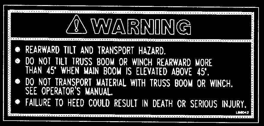
16 SAFETY L65929 L L66042 L65928 L65929 L65928 L66042 L /BP PRINTED IN U.S.A.


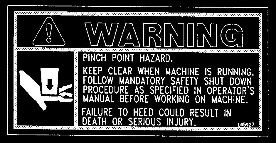

17 SAFETY L65942 L65924 L65926 L65927 L65927 L65927 L65932 L65942 L65932 L65926 L65927 L65924 PRINTED IN U.S.A /BP0204


18 SAFETY L65928 L65927 L65933 L L L65928 L65933 L /BP PRINTED IN U.S.A.
19 SAFETY Rotate Carriage L65927 L66042 Truss Boom PRINTED IN U.S.A /BP0204
20 NOTES /BP PRINTED IN U.S.A.
21 BILLING INFORMATION Gehl Dealer Code: Name: Company: Address: Order Form Safety Training for Operators of Rough Terrain Forklifts PO#: City: State: Zip Code: Phone No.: ( ) Fax No.: ( ) SHIPPING INFORMATION (if different from billing information) Name: Company: Address: City: State: Zip Code: Country: Phone No.: ( ) FAX No.: ( ) Order Qty. $ * ea. OPERATOR TRAINING KIT (P/N ) Includes: Instructor s Guide, Agenda, Objectives and Goals Sheet, Instructor s Resource Guide, Evaluation Test, Evaluation Log Book, Student Material Sets (5), Visual Aids (PowerPoint Disk, Overheads, Charts), AEM Rough Terrain Forklift Safety Manual Order Qty. ADDITIONAL STUDENT MATERIALS (P/N ) (NOTE: 5 sets included in OPERATOR TRAINING KIT) $80.00 * ea. Includes: Operator s Workbooks (5), Operator Certificates of Completion (5), Operator Wallet-Size Completion ID Cards (5) * Call for current prices. FAX or Mail to: Gehl Company 143 Water Street West Bend, Wi U.S.A. FAX Number: (800) Telephone: (262) (Remove this page at perforation to use as Fax or Mail order form) PRINTED IN U.S.A /BP0204
22 INTENTIONALLY BLANK (May be removed at perforation as Fax or Mail order sheet) /BP PRINTED IN U.S.A.
23 NOTES PRINTED IN U.S.A /BP0204


24 Chapter 5 INDICATORS AND CONTROLS CAUTION Become familiar with and know how to use ALL safety devices and controls on the Telescopic Handler BEFORE operating it. Know how to stop the machine operation BEFORE operating it. This Gehl machine is designed and intended to be used ONLY with a Gehl Company attachment tool, or a Gehl Company approved accessory or referral attachment tool. The Gehl Company cannot be responsible for safety if the machine is used with an unapproved accessory or attachment tool. GUARDS AND SHIELDS Whenever possible and without affecting machine operation, guards and shields are used to protect potentially hazardous areas. In many places, decals are also provided to warn of potential dangers and to display special operating procedures. WARNING Read and thoroughly understand all safety decals on the Telescopic Handler BEFORE operating it. DO NOT operate the machine unless all factory-installed guards and shields are properly secured in place. ALTERNATOR BRAKE FAILURE KEY SWITCH START BUTTON ENGINE OIL DASH PANEL AREA CIRCUIT BREAKER TRANS. OIL Keyswitch and Start Button HORN BUTTON Keyswitch OFF: When the key is vertical in the keyswitch, power from the battery is disconnected to the control and instrument panel electrical circuits. Also, this is the only position in which the key can be inserted or removed. Keyswitch ON: When the key is turned one position clockwise from the vertical (OFF) position, power from the battery is supplied to all control and instrument panel electrical circuits. NOTE: If the engine requires repeated attempts to start, the key MUST be returned to the OFF position between starting attempts to prevent battery run down. Start Button: With keyswitch in the ON position, depress the button to activate the starter. Release it as soon as the engine starts /BP PRINTED IN U.S.A.


 should be followed and required repairs made immediately.")


25 Circuit Breaker: The 15-amp breaker protects dash and engine electrical circuits. If it is not in the depressed position, the gauges and indicators on the dash will not work and the engine will shut off. Horn Button: With the keyswitch ON, depress the horn button to activate horn. Park Brake ON: A buzzer located behind the dash sounds as long as the park brake lever is engaged, if the transmission is in forward or reverse. Transmission Oil Temperature: This lamp indicates whether the transmission oil is at the proper operating temperature. During normal operation this lamp should be off, indicating that the transmission oil system is at the proper temperature. IMPORTANT: If this lamp comes ON during normal operation, a problem may exist in the transmission oil system. Stop the machine immediately and investigate the cause of the problem. Alternator Lamp: Indicates the condition of the electrical charging system. During normal operation this lamp should be off. If the charge rate is too high or too low, this lamp will come on. Brake Failure Lamp: The front and rear brakes are on independent brake line systems. If during normal operation with the brake pedal depressed, a loss of pressure occurs in either system, the brake failure lamp will come on. Failure in one line of the system does not affect the operation of the other system line. However, the MANDATORY SAFETY SHUTDOWN PROCE- DURE (page 8) should be followed and required repairs made immediately. During normal operation the lamp should remain off. Engine Oil Pressure Lamp: Indicates whether sufficient engine lubricating oil pressure is present or not. During normal operation, with the engine running, this lamp should be off. During starting and when the engine is not running with key in the ON position, this lamp will be on. IMPORTANT: If this lamp comes ON during normal operation with the engine running, STOP the engine immediately. After allowing the oil to drain down for a few minutes, check the engine oil level. Maintain oil level at the FULL mark on the dipstick. FUEL GAUGE Hourmeter: Indicates the operating time of the machine and should be used for keeping up the maintenance log. Coolant Temperature Gauge: Indicates the temperature of the engine coolant. Under normal conditions, this gauge should indicate approximately 185 F (85 C). Fuel Level Gauge: Indicates the amount of fuel remaining in the fuel tank. Load Charts: A series of flip charts show lift height and reach limits relative to the load weight being handled with various attachment tools. MAIN and STEERING TEST PORT COOLANT TEMP. TEST PORTS HOURMETER JOYSTICK TEST PORT LOAD CHARTS Hydraulic Pressure Test Port: A test gauge can be inserted to check main and steering system pressures, and joystick pressure. PRINTED IN U.S.A /BP0204


26 Switch Panel Windshield Washer: Used to apply cleansing agent while activating the windshield wipers. Clutch Cutout: When activated, it allows greater engine acceleration and power to the hydraulic system without power to the drive axles while the service brake pedal is depressed. In the off position, the clutch mechanism of the transmission remains engaged when applying the brakes. In the on position, the clutch mechanism is disengaged while applying the brakes. Normal brake force will hold the machine in position while accelerating the engine to power hydraulic control functions during load placement. NOTE: The switch panel also includes control switches for the following accessories used with the cab enclosure option. Heater: Provides circulating heated air throughout the cab interior. Heater/AC: This switch turns on or off either heating or cooling selection for the operator s station interior. Units without air conditioning have only the heater mode switch. Lights Option: Work lights may be added to the operator station and boom to provide illumination for forward travel and work operations. Windshield Wiper: Wiper motors can be activated with this switch to maintain proper visibility for the operator through the windshield and the top of the operator s station. SWITCH PANEL Turn Signal: This switch is used to indicate the direction of a turn. Depress the arrow which indicates the direction of your turn. Hazard: This switch can be activated to make the tail lights flash off and on if the machine is stalled or temporarily stopped in a traffic area on the road or jobsite. Cold Starting: This switch activates the injection of an ether agent for faster engine start in cold weather. Engine Fault Override Shutdown Switch: Pressing the override shutdown switch will override an engine shutdown signal. The switch must be pressed within 30 seconds to prevent undesired shutdown of the engine. The switch can be overridden for 30 seconds at a time to move the machine to a safe location and to lower the boom to the ground. If the engine shutsdown, the ignition switch must be turned off and then back on before the engine can be restarted. NOTE: Holding the switch continously ON will not reset the 30 second timer. NOTE: Only machines equipped with the engine shutdown protection have this switch. Travel Controls These controls are used to maneuver the machine around the jobsite or for road travel. Decals on the dash area provide graphic representation of the various control actions. Steering: The power steering motor is designed to provide low-effort steering with no shock reaction from the axle wheels to the steering wheel. Turn the steering wheel to the right or left to turn the machine in the direction of wheel turn action. Steer Select: Use 2-wheel mode for higher speed travel. Use 4-wheel mode for making tighter turns, usually on jobsite. Use crab mode when a small /BP PRINTED IN U.S.A.


27 STEER SELECTOR SPEED and TRAVEL DIRECTION SELECTOR amount of side shift is needed for picking or placing loads. NOTE: The rear wheels are not self-centering. Make sure all wheels are in a straight ahead position before changing the selector mode. Any of the steering position modes can be used in forward or reverse travel. The operator should learn to anticipate changes in machine movement if the steering selector mode must be changed. Parking Brake: Functions as both a parking brake and emergency brake. The parking brake handle is linked by a cable to a brake assembly on the transmission output shaft. WARNING Unattended machine hazard. STEERING PARKING BRAKE Set parking brake and lower attachment tool to ground before leaving machine. An unattended machine can move or roll and cause death or serious injury to operator or bystanders. Periodically check the parking brake tension and adjust, if required, to maintain adequate holding power. Always be sure the parking brake lever is off when resuming machine operation. The parking brake may be used as an emergency stopping system on relatively level terrain if the service brakes fail. When properly adjusted and maintained it meets ANSI test requirements providing 35% of service brake performance at 20 lbs. (89 N) hand lever effort. Travel Direction Selector: Changes the direction of travel between forward and reverse. The selector MUST be in N (NEUTRAL) position before the engine will start. Position F (FORWARD) Position N (NEUTRAL) Position R (REVERSE) NOTE: Backup alarm automatically sounds with travel lever in reverse. IMPORTANT: Care should be taken when downshifting or reversing as damage to the transmission can occur if shifting is forced or attempted at too high a speed. Allow engine RPM to slow before any shift down or directional change is attempted. Speed Range Selector: Twist the outer end of the direction selector counter-clockwise or clockwise to change the transmission speed between low, medium, and high range. Position 3 Position 2 Position 1 HIGH RANGE MEDIUM RANGE LOW RANGE Adjustable Steering Wheel: The steering wheel can be adjusted to one of five positions for operator comfort. Push the small black handle on the left side of the steering console and re-position the steering wheel. Release the handle to lock in place. STEERING WHEEL ADJUSTMENT To adjust the tension, insert a flat blade screwdriver through the hole in the top of the hand grip on the brake lever, and turn the screw until a pull effort of 20 lbs. (89 N) is achieved on the hand lever. SPEED SELECTOR PRINTED IN U.S.A /BP0204


28 BRAKE PEDAL THROTTLE PEDAL To tilt the attachment tool up, move the joystick handle rearward. To tilt the attachment tool down, move the joystick handle forward. BRAKE FLUID FRAME LEVEL and ATTACHMENT TILT JOYSTICK BOOM JOYSTICK SEAT POSITION FLOOR AND SEAT AREA Throttle Pedal: This is right-foot operated and controls the engine RPM to match increased power requirements. Pushing down on the pedal increases the RPM. Letting up on the pedal decreases RPM. Service Brake Pedal: Depressing this pedal activates inboard hydraulic wet-disc-type brakes on all four wheels. Separate front and rear brake systems allow brake power to bring the machine to a safe stop, if either system loses pressure. Seat Positioning: The seat is mounted on rails for forward or rearward repositioning to accommodate operator s size and comfort. A spring-loaded latch handle under the front of the seat activates the adjustment mechanism. Suspension Seat Option: Option is available for additional operator comfort. It is adjustable for a soft or firm ride. Brake Fluid Reservoirs: Located under hinged cover on the cab floor. RIGHT SIDE PANEL These controls and indicators are used to position the frame, boom and attachment. Graphic symbols on the side panel illustrate the control actions. Frame Level/Tilt Joystick: The machine may be tilted slowly 10 o to the left or right to level the frame and boom in relation to the ground. Move the joystick handle to the left to level the frame to the left. Move the joystick handle to the right to level the frame to the right. OPTIONAL JOYSTICK (not shown) Bubble Indicator: Located in front of the operator on the ROPS/FOPS upper cross tube. Movement of the bubble shows when the frame is level relative to sloping ground surface. BUBBLE INDICATOR WARNING DO NOT level the frame with the boom raised or extended. Only level the machine while stopped with the boom fully retracted and the attachment raised just enough to clear the ground. The inner boom nose section has an attachment carrying device feature called the Quick-attach System. This provides the operator with a convenient means of utilizing optional attachment tools. Refer to the OPERA- TION AND ADJUSTMENTS chapter for changing attachment tools procedures. Once the operator tilts the attachment tool to a desired angle, that angle will be maintained as the boom is raised or lowered, extended or retracted, until a new angle is desired /BP PRINTED IN U.S.A.


29 Boom Joystick: This machine has a hydraulic type boom with telescopic sections. The sections extend by means of a hydraulic cylinder and chain system inside the boom, sequenced for uniform extension of each section. To extend the boom, move the joystick handle to the right. To retract the boom, move the joystick handle to the left. To raise the boom, move the joystick handle rearward. To lower the boom, move the joystick handle forward. WARNING Use extreme caution when raising or extending the boom. The Telescopic Handler MUST be level. Loaded or empty, this machine can tip if not level. ALWAYS place the transmission in neutral, set the parking brake and keep the service brake pedal applied before raising or extending the boom. NEVER exceed the specified lifting or extending capacities of this machine. Serious machine damage or personal injury may result. Refer to the load zone charts in the operator s station or this manual. If a boom circuit hose should break with the boom up, with or without a load, shut down the machine following the MANDATORY SAFETY SHUTDOWN PROCEDURE. DO NOT attempt repairs. Call your Gehl dealer immediately for assistance. The truss boom and winch attachment tools should ONLY be used to lift and place loads when the machine is in a stationary position. DO NOT use to transport loads around the jobsite. This can cause the load to swing, resulting in either the load dropping or machine tipover. NEVER use winch for lifting or moving personnel. NEVER exceed the maximum rated capacity of the winch (3000 lbs., 1360 kg) or exceed the load chart rating for winch applications. DO NOT tilt the truss boom back more than 45 o from horizontal. DO NOT attempt to use the optional rotating carriage as a load leveling function. Always level the frame prior to raising a load. Boom Angle Indicator: Mounted on the left side of the outer boom. The position of the bubble in the Boom Angle Indicator, shows the angle of the boom relative to the ground surface. BOOM ANGLE INDICATOR Optional Attachments Joystick: For other attachment options that require additional hydraulics, a 2-position joystick is provided. OTHER OPERATION INDICATORS The following indicators are for fluid level and operator rear vision/safety. Hydraulic Reservoir Oil Level and Fill Cap: The dipstick on the fill cap of the reservoir indicates the level of the hydraulic oil in the reservoir. Side Mirror: Located on the front outside corner of the hydraulic reservoir, provides the operator with a view of the right side and rear area of the machine. ACCESS COVER HYDRAULIC RESERVOIR HYDRAULIC FILL CAP/DIPSTICK MIRROR PRINTED IN U.S.A /BP0204


30 Transmission Oil Level: The dipstick is located under the access cover on the front hood section. Battery Compartment: The battery is located under the access cover on the front hood section. TRANS. DIPSTICK BATTERY ATTACHMENT TOOLS Gehl offers a versatile range of attachment tools to meet various lifting and material handling applications for this machine. Contact your area Gehl dealer for specifications and ordering information. ACCESSORIES Gehl offers a versatile range of special accessories for this machine. Contact your area Gehl dealer for specifications and ordering information. Engine Oil Level: The dipstick is located on the leftside of the engine. Engine Coolant Level: The radiator cap is located under the opening toward the rear of the main hood section. NOTE: All accessories are field-installed unless otherwise noted. Information and parts for field installing of accessories will be provided by the Gehl Company or Gehl Telescopic Handler dealers. Backup Alarm: Located inside the rear frame cover, it produces a loud warning sound whenever the machine is in reverse. BACKUP ALARM /BP PRINTED IN U.S.A.
31 Chapter 6 OPERATION AND ADJUSTMENTS GENERAL INFORMATION ENGINE BREAK-IN CAUTION BEFORE starting the engine and operating the Telescopic Handler, review and comply with ALL safety recommendations set forth in the SAFETY chapter of this manual. Know how to STOP the machine before starting it. Also, BE SURE to fasten and properly adjust the seat belt. Your new engine does not require extensive breakin. However, for the first 100 hours of operation, keep the following in mind: Allow the engine to idle for a few minutes after every cold start. DO NOT idle the engine for long periods of time. DO NOT operate the engine at maximum power for long periods of time. Check the oil level frequently and replenish, as necessary. John Deere engines use a break-in oil for the first 100 hours of operation. After the first 100 hours of operation, change the oil and replace the oil filter. Consult the LUBRICATION chapter or your engine manual for the type and grade of oil to use. Refer to the SERVICE AND STORAGE chapter for the proper service intervals. PRESTART INSPECTION It is the operator s responsibility to inspect the machine before the start of each workday. Every Prestart Inspection must include more than simply checking the fuel and oil levels. It is a good practice to personally inspect any machine you are assigned to use, even though it has already been put into service by other personnel. The most efficient method of checking a machine is by conducting a Walk-Around Inspection. BEFORE STARTING ENGINE Before starting the engine and running the machine, refer to the INDICATORS AND CONTROLS chapter and familiarize yourself with the various operating controls, indicators and safety features. STARTING THE ENGINE Before mounting the operator s compartment, walk completely around the machine to be sure no one is under, on, or close to it. Let others in the area know you are going to start up, and wait until everyone is clear of the machine. WARNING ALWAYS fasten your seatbelt BEFORE starting the engine. Leave the parking brake engaged until the engine is running and you are ready to operate the machine. The following procedure is recommended for starting the engine: 1. Carefully step up and grasp the hand holds to step into the operator s compartment. 2. Adjust the seat and fasten the seatbelt. 3. Check that all controls are in their neutral positions, except the parking brake lever, which should be in the ON position. 4. Adjust the position of the steering wheel tilt to provide comfortable handling. 5. Turn the keyswitch to the ON position and press the start button. If the button is released before the engine starts, turn the keyswitch to the OFF position, and allow the starter to stop before attempting to start again. PRINTED IN U.S.A /BP0204
32 IMPORTANT: Crank the starter until the engine is started. If the engine fails to start within 30 seconds, return the key to the OFF position, wait 2 minutes, and try to restart the engine. Cranking the engine for longer than 30 seconds will result in premature failure of the starter. 6. After the engine starts, allow a sufficient warm-up time before attempting to operate the controls. 7. Check that indicators are in normal condition. 8. Check that there are no fuel, oil or engine coolant leaks, and no abnormal noises or vibrations. COLD STARTING PROCEDURES A block heater or lower radiator hose heater is recommended for starting in temperatures of 20 o F (-7 C) or lower. See your Gehl dealer for recommended heater. If prevailing temperature is 40 o F (4 C) or below, it may be necessary to use a cold weather starting aid to start the diesel engine. For proper use of starting aids, check instructions in the engine manual. If the battery becomes discharged and fails to have sufficient power to start the engine, jumper cables can be used to obtain starting assistance. Refer to the jump starting instructions in the SERVICE AND STORAGE chapter of this manual for safe jumpstart procedure. STOPPING The following procedure is the recommended sequence for stopping the machine: 1. Bring the machine to a stop on a level surface. Avoid parking on a slope, but if neccessary park across the slope and block the tires. 2. Fully retract the boom and lower the attachment to the ground. Idle the engine for gradual cooling. 3. Place controls in neutral. Set the parking brake lever to ON. 4. Turn the keyswitch key to the OFF position. Remove the key. 5. Unlatch the seat belt, and grasp the hand holds while climbing out of the operator s compartment. FIRST TIME OPERATION Be sure the engine is warm and then go through the following procedures. Place the travel lever in a speed range and in forward or reverse direction. Release the parking brake lever and move slowly, while testing the steering and brakes. Stop and operate all boom functons and frame leveling controls, checking for smooth response. Apply the service brakes, stop the machine and move the travel selector to the opposite direction (forward or reverse). Shifting to the next higher gear may be done at any engine RPM while the machine is in motion. DO NOT overspeed the engine when down shifting. Allow the machine to slow down before shifting to the next lower gear. ENGINE SHUTDOWN PROTECTION NOTE: Only machines that have the engine fault override shutdown switch described on page 24 have this feature. The engine is equipped with a WARNING and SHUT- DOWN feature to warn of low engine oil pressure and of high engine coolant temperature. If the problem is not corrected, engine power will derate, or the engine will shutdown. Engine Oil Pressure CAUTION Be sure the area used for test-running is clear of spectators and obstructions. Initially, operate the machine with an empty attachment tool. There are two low oil protection features: Low Oil Pressure WARNING, and Low Oil Pressure SHUT- DOWN. At the Low Oil Pressure WARNING set-point, the warning light in the engine override switch will flash and a slow engine power derate will begin. If the oil pressure rises above the Low Oil Pressure WARNING set-point, power will slowly increase until the engine is back to full power. The light will continue to flash until the power has returned to normal, even if the fault condition has been corrected and the recovery is in process. At the Low Oil Pressure SHUTDOWN set-point, the /BP PRINTED IN U.S.A.
33 light in the engine override switch will light continously, and a fast engine power derate will begin. If the oil pressure does not rise above the SHUTDOWN setpoint within 30 seconds, the engine will shut down. If the oil pressure rises above the Low Oil Pressure SHUTDOWN set-point within 30 seconds, then the power derate speed will revert to the Low Oil Pressure WARNING speed of reaction. Engine Coolant Temperature There are two coolant temperature features: High Coolant Temperature WARNING, and High Coolant Temperature SHUTDOWN. At the High Coolant Temperature WARNING setpoint, the warning light in the engine override switch will flash and a slow engine power derate will begin. If the coolant temperature drops below the High Coolant Temperature WARNING set-point, the power will increase slowly until the engine is back to full power. The light will continue to flash until the power has returned to norma,l even if the fault condition has been corrected and the recovery is in process. At the High Coolant Temperature SHUTDOWN setpoint, the light in the engine override switch will light continously, and a fast engine power derate will begin. If the coolant temperature does not drop below the SHUTDOWN set-point within 30 seconds, the engine will shut down. If the coolant temperature drops below the High Coolant Temperature SHUTDOWN set-point within 30 seconds, the power derate speed will revert to the High Coolant Temperature WARNING speed of reaction. PARKING BRAKE NOTE: The parking brake mechanism is NOT designed for, OR intended to be used as, the primary means of stopping movement of the machine. Hydraulic braking provided through the service brakes within the axle is the primary means for stopping movement. The proper sequence for correct machine operation is to always engage the parking brake lever before shutting off the engine, and to disengage the parking brake ONLY after the engine is running. In an EMER- GENCY, if it becomes necesary to STOP movement, pull the parking brake lever to ON. CHANGING ATTACHMENT TOOLS The Telescopic Handler boom nose will accept Quickattach System Gehl attachment tools. The Quick-attach System has a quick-release hookup and locking mechanism for mounting framing, masonry, and material handling-type attachment tools to the boom nose. Hookup Ear Hookup Bar Tilted Forward For Hookup Attachment Tool Locked Quick-Attach System Attaching Detail Attachment Tool Attaching - Using Quick-Attach System To attach the attachment tool, proceed as follows: 1. Raise the boom slightly and extend it 2 or 3 feet ( m) for better visibility and tilt the Quickattach System forward. 2. Align the Quick-attach System squarely with the back of the attachment tool. 3. Slowly extend the Quick-attach System and lower the hooks under the attachment tool hookup bar. 4. Tilt the Quick-attach System back so that the lock plate engages the attachment tool. This secures the attachment tool to the Quick-attach System. 5. For attachment tools with auxiliary hydraulics, connect the hoses to the quick-connect connectors on the boom nose. PRINTED IN U.S.A /BP0204
34 Attachment Tool Released Attachment Tool Unlocked Manually For Release 6. Start the engine and roll the Quick-attach System forward, and then slowly back the machine away until the attachment tool is free from the boom nose. SELF-LEVELING WARNING Modifications, alterations to, or use of attachment tools not authorized by Gehl Company can void the warranty and cause machine damage, and may result in serious personal injury or death. The machine is provided with a hydraulic self-leveling feature. This feature is designed to keep the attachment tool level while the boom is being raised. Quick-Attach System Detaching Detail Detaching - Using Quick-Attach System To detach the attachment tool, proceed as follows: 1. Raise the boom slightly and extend it 2 or 3 feet ( m) for better visibility. Lower the boom until the attachment tool is approximately 1 foot (0.3 m) off the ground. 2. Roll the carrier back as far as it will go. Once the carrier is rolled back all the way, perform the MANDATORY SAFETY SHUTDOWN PROCE- DURE (page 8, Safety chapter). 3. With the engine off, leave the operator s station. Manually raise the lock spring and flip the lock plate up and outward at least 180 o so it is in position to re-lock on the next attachment tool. 4. Tilt the Quick-attach System forward to allow the attachment tool to roll out, then lower the boom so the hook ears clear the hookup bar on the attachment tool. NOTE: One side of the lock plate has a bright red decal to indicate the unlocked position. 5. If the attachment tool has auxiliary hydraulics, disconnect the hoses from the quick-connect connectors on the boom nose. GENERAL MACHINE OPERATION Take time to check the Telescopic Handler to be sure all systems are in good operating condition. Perform the following steps before starting the machine for the first time each day. 1. Check the engine oil and coolant, transmission oil and hydraulic oil levels. 2. Be sure weekly lubrication has been done. 3. Visually inspect for leaks, broken or malfunctioning parts. Make sure all caps, covers and safety shields are in place. WARNING Exhaust fumes can kill. Ensure proper ventilation when starting indoors or in enclosed areas. Use proper grab handles, NOT the steering wheel or control levers as hand holds when mounting and dismounting. NEVER operate the machine with safety guards or covers removed. Over-inflated tires can explode and cause injury or death. Tire repairs MUST be made only by authorized personnel using proper tools and equipment /BP PRINTED IN U.S.A.
35 4. Check tires for cuts, bulges, nails, correct pressure, loose wheel nuts, etc. 5. Inspect the work area. Be sure you know where you will make load pickups, lifts and turns. Look over the jobsite for holes, obstacles, slippery surfaces, soft terrain or deep mud. 6. Check clearances of ramps, doorways and passage ways. Check overhead clearances if you will travel and place loads near power or telephone lines. If the machine is found to be in need of repair or in any way unsafe, or contributes to an unsafe condition, the matter must be reported immediately to the appropriate authority. The machine must NOT be operated until it has been restored to a safe operating condition. Operate the travel controls gradually and smoothly when starting, stopping, turning and reversing direction. Grade and Slope Precautions The Telescopic Handler complies with industry stability tests requirements and is stable when properly operated. However, improper operation, faulty maintenance, and poor housekeeping can contribute to a condition of instability and defeat the purpose of the standard. The amount of forward and rearward tilt to be used is governed by the application. Although use of maximum rearward tilt is allowable under certain conditions, such as traveling with the load fully lowered, the stability of the machine, as determined by the industry standard tests, does not encompass consideration for excessive tilt at high elevations, or the handling of offcenter loads. Handle only loads within the capacity limits of the machine, and that are stable and safely arranged. When attachments are used, extra care should be taken in securing, manipulating, positioning and transporting the load. Grade Limits NOTE: Grade limits are based on ANSI/ASME standard B This telescopic handler meets or exceeds the safety standard (ASME B56.6) stability limits for rough terrain forklifts. The stability tipping limits cover specific, controlled test conditions, which are extremes, and which are not intended to be achieved during normal work site operations. The following specifications are provided only as information to the operator, and must not be used as a guideline for operating the telescopic handler. For safe operation, always follow the instructions and warnings provided in this manual. 1. DO NOT place or retrieve loads on an up or down slope or grade that exceeds 7% or 4 o grade. 2. DO NOT travel up or down a grade or slope that exceeds 22% or 12 o grade while loaded. 3. DO NOT place or retrieve loads on a side hill with a slope or grade that exceeds 12% or 7 grade. Regardless of terrain or position of wheels, the FRAME MUST BE LEVEL as indicated by the bubble indicator on the ROPS/FOPS cross member. 4. DO NOT travel across a side hill that exceeds 18% or 10 grade. Regardless of the terrain or position of the wheels, the FRAME MUST BE LEVEL as indicated by the bubble indicator on the ROPS/FOPS upper cross member. Furthermore the attachment tool MUST be maintained in the carry position, with the boom fully retracted, and the attachment tool at minimum ground clearance. When ascending or descending grades in excess of 5% or 3, the machine should be driven with the load upgrade. An unloaded machine should be operated on all forward grades with the load handling attachment tool downgrade, tilted back if applicable, and raised only as far as necessary to clear the road surface. Avoid turning if possible and use extreme caution on grades, ramps and inclines. Normally travel straight up and down the slope. WARNING DO NOT level the frame with the boom raised or extended. Only level the frame while stopped, and with the boom fully retracted and the attachment tool raised just enough to clear the ground. Traffic Flow Patterns Know and understand the traffic flow patterns of your jobsite. Know all Telescopic Handler hand signals for safety. Utilize signalpersons and be sure you can see the signal person and acknowledge the signals given. PRINTED IN U.S.A /BP0204
36 DO NOT move railroad cars and trailers with the forklift truck. DO NOT use the boom and attachment for leverage to push the machine out of mud. Stop Raise Load Lower Load IMPORTANT: DO NOT lower boom at high engine RPM when attachment tool is at maximum rearward tllt. Damage to slave cylinders may result. Rotate Forks Right Rotate Forks Left Tilt Forks Up GENERAL LOAD HANDLING NEVER attempt to work controls except from the operator s seat. NEVER jerk or use fast movements. Avoid sudden stops, starts and changes in direction. Tilt Forks Down Load Back Load Forward Safety Hand Signals The backup alarm automatically sounds with the travel direction selector in reverse. Care should be taken when down shifting or reversing, because damage to the transmission can occur if shifting is forced or attempted while traveling. When ramps MUST be used in transporting loads with the machine, the following are the minimum widths for safe travel: Compacted dirt, gravel, etc ft. (3.6 m) Woodboard, concrete, etc ft. (3 m) Permanent aisles, roadways and passageways, floors and ramps must be clearly defined or marked. Permanent or temporary protrusion of loads, equipment, material and construction facilities into the usual operating area must be guarded, clearly and distinctively marked, or clearly visible. Maintain a safe distance from the edge of ramps, platforms and other similar working surfaces. Controlled lighting of adequate intensity should be provided in operating areas. Where operating conditions indicate, the operator/user is responsible for having the machine equipped with lights. Provisions must be made to prevent trucks, semi-trailers and railroad cars from being moved during loading and unloading. Wheel stops, parking brakes, or other positive holding means must be used to prevent movement during loading and unloading. Operation of the hydraulic system depends on engine speed and the distance the controls are moved. When operating these controls it is important to develop a technique called feathering. Feathering the control means you start the desired motion by moving the control away from neutral a small amount. After movement has started, the control can be eased to full movement. Use the same technique to stop the motion. WARNING Excessive speed can be hazardous. ALWAYS exercise caution and good judgement while operating the machine. Twice daily, increase the engine speed (fast idle) and extend and retract the frame leveling cylinder to the stroke limit. This removes any air trapped in the circuit, which could cause the machine to lean to one side or the other. The machine must not be used to lift or carry personnel, or be fitted with any form of personnel work platform. ALWAYS maintain a safe distance from electric power lines, and avoid contact with any electrically charged conductor or gas line. It is not necessary to make direct contact with a power line for power to ground through the structure of the machine. Keep the boom at least 10 ft. (3 m) from all power lines. Accidental contact or rupture can result in electrocution or an explosion. Contact the North American One-Call Referral System at (888) for the local Digger s Hotline number or proper local authorities for utility line locations BEFORE starting to dig! /BP PRINTED IN U.S.A.
37 Keep all body parts inside the operator s station while operating the machine. BE SURE of clearance for the attachment tool when turning, working around buildings, etc. Turning corners too fast can tip the machine, or cause a load to tip off the attachment. Sudden slowing or stopping of the machine may cause the load to drop off the attachment tool. Be certain you can control both speed and direction before moving. Always place the machine in neutral and set the parking brake before raising or extending the boom. NEVER drive the machine up to someone standing in front of the load. NEVER leave the operator s station without first lowering the attachment tool to the ground. Set the parking brake, place controls in neutral, shut off the engine and remove the key. AVOID parking the machine on a slope, but if necessary, park across the slope and block the tires. Load Capacity and Reach This machine has flip-charts in the operator s station that provide, at a glance, the capacity limits at various positions of attachment tool extension and elevation. A set of load zone charts is reproduced at the end of this manual for reference. A typical load zone chart is shown below. The scale on the left indicates height in feet above ground level. The scale on the bottom shows the distance in feet out from the front of the machine. The arc lines noted by the numbers 1 through 5 correspond with the position extension markers on the operator side of the intermediate boom section. The following example illustrates proper use of the load zone charts for the Telescopic Handler: Example: The operator, using a standard carriage attachment tool, wants to raise a 2000 lb. load 20 feet high, and can only get to within 15 feet of the load placement point. Can it be done within the capacity of the machine? Analysis: See Typical Load Zone Chart below. HEIGHT ABOVE GROUND BOOM EXTENSION MARKERS REFERENCE DISTANCE LOAD IS EXTENDED Typical Load Zone Chart PRINTED IN U.S.A /BP0204
38 Projecting up from the 15 foot mark on the horizontal axis to intersect a line through the 20 foot mark on the vertical axis shows the load can be placed in the 2000 lb. zone. During placement, the operator observes when the extension reference number 3 on the boom is visible and stops. The maximum safe distance of extension with this load has been reached. LIFTING ATTACHMENT TOOL APPLICATIONS Picking Up the Load Inspect the load. If it appears unstable, DO NOT attempt to move it. DO NOT attempt lifting doubletiered loads, or straddling side-by-side pallets with one on each fork. NEVER add extra unauthorized counterweights to this machine. Consider the additional weight of any attachment tool as part of the picking load capacity of the machine. Approach the load squarely and slowly with the machine straight and level. Adjust the space between forks, if necessary. Engage the load equally on all forks until the load touches the carriage backrest. Tilt the forks back to position the load for travel. Carrying the Load WARNING NEVER exceed the rated operating capacity of the Telescopic Handler as shown on the capacity decal. WARNING Operating conditions can reduce the machine s safe operating capacity. Exceeding capacity when raising or extending the boom will cause the machine to tip forward. If the load obstructs your view, get someone to direct you. Maintain ground speeds consistent with ground conditions and that permit stopping in a safe manner. WARNING NEVER travel with the boom above the carry position (attachment tool should be at minimum ground clearance). Boom should be fully retracted. Use lower gear when traveling down an incline. NEVER coast with the transmission in neutral. Travel up and down grades slowly. DO NOT operate the machine on a slope or grade that exceeds 22% or 12 o. Load Elevation and Placement For ground level placement, be sure the area under the load and around the machine is clear of equipment and personnel. Lower the load to the ground, tilt the forks to the horizontal position, then back away carefully to disengage forks from the load. For elevated or overhead placement, bring the machine as close as possible to the landing point. Level the machine BEFORE raising the load. Use extreme caution for high placement. Be sure personnel are clear of the area where the load or the machine could tip or fall. Set the parking brake, hold the service brake pedal fully applied and slowly raise the load, maintaining a slight rearward tilt to cradle the load. As the load approaches the desired height, feather the boom control at minimum speed until the load is slightly higher than the landing point. Continue the feathering technique and lower the load into place, until the forks are free. Level the forks and retract clear of the load. Lower the forks to travel height before moving the machine. WARNING NEVER use frame leveling to position an elevated load. Always lower the load to the ground and reposition the machine. If a hydraulic boom circuit hose should break with the boom up, shut down the machine. DO NOT attempt to bring down the boom or make repairs. Call your Gehl dealer immediately /BP PRINTED IN U.S.A.
39 As lift height increases, depth perception decreases. High elevation placements may require a signal person to guide the operator. The machine becomes less stable as the load is raised higher. DO NOT ram the lift cylinders to the end of the stroke. The resulting jolt could spill the load. The truss boom attachment tools should ONLY be used to lift and place loads when the machine is in a stationary position. DO NOT use to transport loads around the jobsite. This can cause the load to swing, resulting in either the load dropping or machine tipover. SUSPENDED LOADS The handling of suspended loads by means of the truss boom or other similar device can introduce dynamic forces affecting the stability of the machine that are not considered in the stability criteria of industry test standards. Grades and sudden starts, stops and turns can cause the load to swing and create a hazard. DO NOT exceed the Telescopic Handler capacity as equipped for handling suspended loads. Only lift the load vertically and NEVER drag it horizontally. Use tag lines to restrain load swing whenever possible. Guidelines for Free Rigging/Suspended Loads 1. The rigging equipment must be in good condition and comply with the applicable U.S. OSHA Regulation , Slings, or Rigging equipment for material handling. be positioned over personnel at any time. ROAD TRAVEL For short distance highway travel, attach an SMV (Slow-Moving Vehicle) emblem (purchased locally) to the back of the Telescopic Handler. Activate hazard lights on the machine. For highway operation, obtain and install an amber flashing beacon. NOTE: ALWAYS follow ALL state and local regulations regarding the operation of equipment on or across public highways! Whenever there is an appreciable distance between jobsites, or if operation on public highway is prohibited, transport the machine using a vehicle of appropriate size and weight. TRANSPORTING BETWEEN JOBSITES When transporting the Telescopic Handler, know the overall height to allow clearance of obstructions. Remove or tape over the Slow Moving Vehicle (SMV) emblem if it will be visible to traffic. ALWAYS abide by the following recommended procedures and guidelines when using ramps to load the machine onto (or unload it from) a truck or trailer. Failure to heed can result in damage to equipment and serious personal injury or death! Tie-down hooks are provided for inserting chains through to secure the machine while transporting. Loading Machine Using Ramps NOTE: A matched pair of ramps is required. 2. The rigging equipment must be secured to the forks such that it cannot slip or slide either sideways or fore and aft. 3. The capacity of the fork(s) and the machine (whichever is less) must not be exceeded. 4. The load center must remain at 24 (610 mm) or less. 5. No lifting of material may be done when anyone is on the load, rigging or forks. 6. Multiple pickup points on the load are preferred to prevent the load from rotating, but a single pickup point may be used if one or more tag lines are utilized. And, of course, the load must never Ramp Placement PRINTED IN U.S.A /BP0204
40 1. The ramps MUST be of sufficient strength to support the machine. Whenever possible, the use of strong steel ramps is recommended as well as some type of center supporting block. 2. The ramps MUST be firmly attached to the truck or trailer bed with NO step between the bed and the ramps. 3. Incline of ramps MUST be less than 15 degrees (ramp length MUST be at least 16 feet (4.9 m) long. 4. Ramp width MUST be at least 1-1/2 times the tire width. 5. Block the front and rear of the tires on the truck or trailer. Engage the parking brake. 6. Position the machine (with the boom facing toward the front of the truck or trailer) so that it is straight in line with the ramps. Tie-down slots are provided on the front and rear sides of the frame structure. Slowly (at the lowest engine speed possible) and carefully drive the machine up the ramps. WARNING NEVER adjust travel direction (even slightly) while traveling on the ramps. Instead, back down off the ramps, and then realign the machine with the ramps. 7. Slowly (at the lowest engine speed possible) and carefully drive the machine down the ramps. THEFT DETERRENTS Gehl has recorded all part numbers and serial numbers. Users should take as many of the following actions as possible to discourage theft, to aid in the recovery in the event that the machine is stolen, and to reduce vandalism: 1. Remove keys from unattended machines. 2. Attach, secure, and lock all anti-vandalism and anti-theft devices on the machine. 3. Lock doors of cabs when not in use. 4. Inspect the gates and fences of the vehicle storage yard. If possible, keep machines in well lighted areas. Ask the law enforcement agency having jurisdiction to make frequent checks around the storage and work sites, especially at night, during weekends, and on holidays. 5. Report any theft to your dealer and insurance company. Provide the model and all serial numbers. Request that your dealer forward this same information to Gehl Company WARNING NEVER transport the machine with the boom raised or extended. BE SURE to secure the machine (including boom) to the truck or trailer bed using chain and binders or steel cables to prevent any movement while transporting. Unloading Machine Using Ramps NOTE: A matched pair of ramps is required. Repeat Steps 1 through 5 and proceed as follows to unload the machine: 6. If necessary, adjust the machine so that the wheels are in line and centered with the ramps /BP PRINTED IN U.S.A.
41 Chapter 7 LUBRICATION GENERAL INFORMATION WARNING NEVER lubricate or service this unit when any part of the machine is in motion. ALWAYS exercise the MANDATORY SAFETY SHUT- DOWN PROCEDURE ( SAFETY chapter) before lubricating or servicing this equipment. Hydraulic System Reservoir Use Mobil DTE 15M, or equivalent that contains anti-rust, anti-foam and antioxidation additives and conforms to ISO VG46. Capacity: 35 Gallons (133 liters) All Grease Fittings Use No. 2 Lithium-based Grease Engine Crankcase Oil NOTE: The Maintenance chapter in this manual has provisions for recording the dates and hourmeter readings after lubrication or other service has been performed. Use those spaces to keep a log for maintaining a current service interval record. Proper routine lubrication is an important factor in preventing excessive part wear and early failure. LUBRICANTS The chart on this page lists the locations, temperature ranges and types of lubricants to be used when servicing this machine. Also refer to the separate engine manual for additional information regarding recommended engine lubricants, quantities required and grades. NOTE: Refer to Operator Services topic in the Service and Storage chapter of this manual for detailed information regarding periodic checking and replenishing of lubricants. GREASING Refer to the illustration and listing on the next page for fitting locations. Wipe dirt from the fittings before greasing them to prevent contamination. Replace any missing or damaged fittings. To minimize dirt buildup, avoid excessive greasing. Ambient Temperature Grade* -22 F - 86 F (-30 C - 30 C) SAE 5W-30-4 F F (-20 C - 40 C) SAE 10W-40 5 F F (-15 C - 50 C) SAE 15W-40 *API Service Classification: CH-4/Cl-4 *API Service Classification for first 100 hours on new or rebuilt John Deere engines: CC or CD Capacity: 10 Quarts (9.5 liters) Axle Gear Oil Use MobilFluid 423 or equivalent Differential Capacity: 9.6 Quarts (9.0 liters) Planetary Capacity (each side): 0.6 Quarts (0.5 liters) Transmission Oil Use Sunco Multi-ATF or equivalent Capacity: 24 Quarts (22.7 liters) Brake System Use Sunco Multi-ATF or equivalent PRINTED IN U.S.A /BP0204
42 REPLACEMENT FILTER CHART AIR FUEL ENGINE HYDRAULIC TRANS. ENGINE TYPE FILTER FILTER OIL FILTER STRAINER OIL JOHN DEERE w/ Mechanical Throttle L L98978 L99420 L97489 L49327 L99184 JOHN DEERE w/ Electronic Throttle L L97489 L49327 L99184 BASIC MACHINE GREASE FITTING LOCATIONS Every 50 Hours (or weekly) Refer to the illustration below for locations. Ref. No. Description Qty. CHASSIS AREA 1 Brake foot pedal linkage Wheel spindle pins (per axle) Tie rod ends (per axle) Axle to frame pivot pins (per axle) Drive shaft, slip joint (per shaft) Drive shaft, U-Joint (per shaft) Level cylinder pivot pins Base end lift cylinder pivot pins Base end slave cylinder pivot pins Ref. No. Description Qty. BOOM AREA 10 Boom to frame upright pivot pins Rod end slave cylinder pivots pins Rod end lift cylinder pins Extend cylinder pivot pins Chain sheave pins Quickattach to boom nose pivot pins Tilt cylinder pivot pins Rotate cylinder pivot pins Rotate carriage wear pads Rotate pivot bearing Boom slide pads - as required, front and rear FRONT SIDE /BP PRINTED IN U.S.A.


43 UNDER COVER PRINTED IN U.S.A /BP0204
44 Chapter 8 SERVICE AND STORAGE GENERAL INFORMATION NOTE: All service routines, with the exception of those described under the Dealer Services topic, are owner-operator responsibilities. All operator services described under the daily subtopics are also referred to on a decal located on the inside right side panel of the operator s station. Refer to the LUBRICATION chapter of this manual for lubrication information. NOTE: This SERVICE AND STORAGE chapter describes procedures to follow for making routine maintenance checks, adjustments and replacements. The majority of the procedures are also referred to in the MAINTENANCE chapter of this manual. For engine-related adjustments and servicing procedures, refer to the engine manual provided. PRECAUTIONS WARNING BEFORE performing any service on the Telescopic Handler, unless expressly instructed to the contrary, exercise the MANDATORY SAFETY SHUTDOWN PROCEDURE (Safety chapter, pg. 8). After service has been performed, BE SURE to restore all guards, shields and covers to their original positions BEFORE resuming machine operation. DO NOT perform any maintenance or repair without the owner s prior authorization. Allow only trained personnel to service the machine. WARRANTY repairs can only be done by an authorized Gehl dealer. Dealers know what portions of the machine are covered under the terms of the Gehl Warranty and what portions are covered by other vendor warranties. When a problem occurs, don t overlook simple causes such as an empty fuel tank. Check for leaks and broken connections. Make note of any specific problem symptoms, noises, etc. and contact your local Gehl dealer. IMPORTANT: Always dispose of waste lubricating oils, anti-freeze and hydraulic fluids according to local regulations or take them to a recycling center for disposal. DO NOT pour them onto the ground or into a drain. DEALER SERVICES The following areas of internal components service, replacement and operating adjustments should only be performed by (or under the direction of) an authorized Gehl Telescopic Handler dealer. IMPORTANT: DO NOT service or repair major components, unless authorized to do so by your Gehl dealer. Any unauthorized repair will void the warranty. POWER TRAIN COMPONENTS The engine and transmission are coupled directly to each other. All service routines related to the internal components are precise and critical to proper power train operation. The axle differential and planetary ends are also sophisticated assemblies that require special know-how and tools for servicing. IMPORTANT: If power train components are suspected of faulty operation, contact your Gehl dealer for further assistance. HYDRAULIC SYSTEM COMPONENTS Valves, pumps, motors and cylinders are also sophisticated assemblies that require special know-how and tools for servicing. All cylinders are appropriately designed with particular strokes, diameters, checks and hose connection provisions unique to the machine application requirements. A schematic (MAINTE- NANCE chapter) can be used as a guide for service reference, as required /BP PRINTED IN U.S.A.
45 WARNING Tilt, lift, extend and leveling cylinders have counterbalance valves. These valves keep hydraulic fluid from entering and exiting the cylinders while they are not being activated, and they are under extremely high pressure. Before removing any of these valves, you ARE REQUIRED to call Gehl Service. Failure to do so may result in serious injury or death. Internal service on any of these components should only be performed by (or under the direction of) an authorized Gehl Telescopic Handler dealer. ELECTRICAL COMPONENTS An electrical system schematic is provided (MAINTE- NANCE chapter) which includes instrumentation, electrical components and switch connections. It can be used as a guide for service reference, as required. OPERATOR SERVICES Some of the operator-related services will require access to components located inside the superstructure under shields, hoods and covers. The reference chart on this page notes components accessed in each particular area. ACCESS TO COMPONENTS REFERENCE CHART Component Operator Frame Front Mid-Rear Station Cover Hood Axle (underside) Engine Transmission (mid area) Drive Shafts (underside) Main Control Valve (rear) Muffler (underside) Air Cleaner (top fuel tank) Battery Radiator Brake Valve (underside) Travel Controls (dash area) Boom Controls (right side) Hydraulic Test Ports (mid area) Hourmeter (dash) Switches/Indicators (dash) Hydraulic Pump Hydraulic Filter (Reservoir) Misc. Hydraulic Valves Air Conditioner (rear) Heater (lower front) PRINTED IN U.S.A /BP0204
46 WARNING DO NOT smoke or allow any open flames in the area while checking or servicing hydraulic, battery or fuel systems; all contain highly flammable liquids or explosive gases, which can cause an explosion or fire if ignited. Wear a face shield when you disassemble spring-loaded components or work with battery acid. Wear a helmet or goggles with special lenses when you weld or cut with a torch. When working beneath a raised machine, always use blocks, jack-stands or other rigid and stable supports. Wear appropriate protective clothing, gloves, shoes. Keep feet, clothing, hands and hair away from moving parts. Always wear safety glasses or goggles for eye protection from electric arcs from shorts, fluids under pressure, and flying debris or loose material when the engine is running or tools are used for grinding or pounding. NEVER weld on bucket, forks, boom, support frame or overhead guards without the consent of the manufacturer. Special metals may be used that require special welding techniques, or that should not have weld repairs. NEVER cut or weld on fuel lines or tanks. If repair welding is ever required, BE SURE to attach the ground (-) cable from the welder as close as possible to the area to be repaired. Also, remove battery positive (+) terminal connection before welding. Choose a clean, level work area. Be sure you have sufficient room, clearances, and adequate ventilation. Clean the walking and working surfaces. Remove oil, grease and water to eliminate slippery areas. Utilize sand or oil absorbing compound, as necessary, while servicing the Telescopic Handler. Before starting inspection and repair, move the machine onto a level surface, shut down engine, and release all hydraulic pressure. Always block the boom securely, or lower it to full ground contact. Place all controls in neutral. Block the wheels. Remove the ignition key. Remove only guards or covers that provide needed access. Wipe away excess grease and oil. Excessively worn or damaged parts can fail and cause injury or death. Replace any cracked or damaged parts. Care should be taken to assure that all replacement parts are interchangeable with original parts and of equal quality. Use care not to damage machined and polished surfaces. Clean or replace all damaged or painted-over plates and decals that cannot be read. After servicing, check the work performed, no parts left over, etc. Install all guards and covers. CHECK FUEL TANK LEVEL After operation each day, the fuel tank should be filled to prevent water from condensing in the tank. To fill, remove the filler cap and add fuel. A drain plug is provided in the bottom of the fuel tank for removing condensation and other foreign materials. Whenever contamination is present in the tank, open the plug and allow water and fuel to drain into a container until only clear fuel is flowing from the tank. CHECK FUEL FILTER WARNING NEVER leave guards off or access doors open when the machine is unattended. Keep bystanders away if access doors are open. Service Every 10 Hours or Daily NOTE: The fuel filter will require occasional replacement to maintain a clean and adequate fuel flow for maximum engine horsepower. The frequency of filter replacement will be determined by the cleanliness of available fuel, the care used in storing fuel supplies and the operating conditions in which the machine is used. Small amounts of water can be drained from the fuel filter. The drain plug should be removed weekly to drain off water accumulation until clear fuel is flowing from the outlet /BP PRINTED IN U.S.A.
47 CHECK ENGINE OIL LEVEL With the machine on level ground, and the engine stopped for ten minutes or more, remove the engine dipstick. Wipe it clean, re-insert it and remove to obtain a reading. If the oil level is down, or below the ADD mark, fill with the required amount of oil to bring the level to the FULL mark. See the LUBRICATION chapter for the type of oil to use. CHECK RADIATOR COOLANT LEVEL With the machine on level ground, remove the radiator cap. Add a 50/50 water and anti-freeze mixture if the coolant level is below the filler neck. Replace the radiator cap securely. IMPORTANT: If the engine is operated with a loose radiator cap, the pressure bypass will not work and the engine will run hot. WARNING DO NOT remove the radiator cap when the engine is running hot or overheated. Coolant is extremely hot and under pressure and it can burn your skin. Allow sufficient time for the radiator to cool BEFORE relieving the pressure and removing the radiator cap. CHECK TRANSMISSION OIL LEVEL The machine must be on level ground with the boom lowered and retracted. With engine and transmission at operating temperature; parking brake on, transmission in neutral and engine speed at low idle, remove the access cover to the transmission and hydraulic pump. Remove the dipstick and check the oil level. Add the required amount of oil to bring the level to the FULL mark. See the LUBRICATION chapter for the type of oil to use. CHECK HYDRAULIC OIL LEVEL The machine must be on level ground with the boom lowered and retracted. The fluid MUST be cool when checking the reservoir level. By doing this, you will reduce the possibility of overfilling the hydraulic system, and also reduce potential injury due to hot fluid. Remove the front cover from the front hood section. Loosen the filler cap to release pressure. Remove the filler cap and check the level on the dipstick. If the oil level is down, or below the ADD mark, fill with the required amount of oil to bring the level to the FULL mark. See the LUBRICATION chapter for the type of oil to use. IMPORTANT: Be careful when removing the reservoir filler cap so that no dirt or other foreign matter enters the hydraulic system while the cap is removed. DO NOT OVERFILL. CHECK BRAKE RESERVOIR LEVELS Flip up the floor cover under the seat mount. Remove both reservoir covers to check the levels. If low, fill to the proper level with correct fluid. See LUBRICA- TION chapter for the type of fluid used. CHECK PARK BRAKE LEVER Check the tension when applied. Adjust, if necessary, to an application force of 20 lbs. (89 N). CHECK TIRE PRESSURES Proper tire pressure should be maintained equally for all four tires to enhance operating stability and extend tire life. When installing tires on the machine, be sure that all tires are of the same size and style. ALWAYS replace tires with the same size furnished as original equipment. Replacement tires must be purchased locally. Check the tire pressure cold. All 12-ply tires should be inflated to 55 PSI (380 kpa). NOTE:If the tires have been filled with water or calcium chloride for weight, a calcium chloride tire pressure gauge MUST be used to check the tire pressure. When removing tires, follow industry safety practices. Deflate completely prior to removal. Following assembly of the tire on the rim, use a safety cage or restraining device while inflating. PRINTED IN U.S.A /BP0204
48 WARNING Inflating or servicing tires can be dangerous. Whenever possible, trained personnel should service and mount tires. To avoid possible death or serious injury, follow the safety precautions below: 1. BE SURE the rim is clean and free of rust. 2. Lubricate both the tire beads and rim flanges with a soap solution. DO NOT use oil or grease. 3. DO NOT place your fingers on the tire bead or rim during inflation. Use a clip-on tire chuck with a remote hose and gauge, which allows you to stand clear of the tire while inflating it. 4. NEVER inflate beyond 35 PSI (240 kpa) to seat the beads. If the beads have not seated by the time the pressure reaches 35 PSI (240 kpa), deflate the assembly, reposition the tire on the rim, relubricate both parts and reinflate. Inflation pressure beyond 35 PSI (240 kpa) with unseated beads may break the bead or rim with explosive force sufficient to cause death or serious injury. 5. After seating the beads, adjust the inflation pressure to the recommended operating pressure listed. 6. DO NOT weld, braze, or otherwise attempt to repair and use a damaged rim. CHECK WHEEL NUT TORQUE On NEW machines, or anytime wheel has been removed, re-torque until 450 ft.-lbs. (610 Nm) is maintained. CHECK INSTRUMENTS OPERATION Allow the engine to warm up for about five minutes before beginning operation. Indicator lamps should be OFF and gauges should register normal readings. Tilt the frame from side to side with the frame leveling control and note the angle indicator movement. CHECK GENERAL MACHINE OPERATION AND CONDITION shields and covers in place? Do all controls function smoothly and properly? Are there any abnormal vibrations or noises? Are any hose or fitting connections leaking? Is the engine exhaust color normal (light grey or colorless)? WARNING Manufacturers of push-pull control cables advise taking the following operation and maintenance precautions. Do not adjust the control cable with the engine running. A gradual or sudden increase in the no-load friction (cable disconnected at both ends) of a control cable is an indication of a pending or present performance problem. The control cable should be replaced. A gradual or sudden decrease in the useable travel is a indication of a pending or present performance problem. The cable should be replaced. Control cables that have moisture inside of them and/or have frozen should be replaced. Do not apply heat to thaw or dry control cables. Control cable are lubricated for the life of the control cable. Do not remove the seals or lubricate the control cable. Control cables are designed to be nonrepairable. Do not attempt to repair control cables. Failure to heed could result in death or serious injury. Service Every 50 Hours or Weekly LUBRICATE GREASE POINTS Refer to the LUBRICATION chapter of this manual for weekly grease fitting locations and other related details. Are any decals missing or damaged? Are all guards, /BP PRINTED IN U.S.A.
49 100 Hours (New Machine Only) The following initial oil and filter changes should be made at this time on a new machine. Thereafter these changes should be made at the regular maintenance schedule listed. Refer to those schedules for procedures necessary. Engine Oil and Filter Transmission Oil and Filter Hydraulic Oil Filter (250 Hours) (1000 Hours) (1000 Hours) Service Every 250 Hours or Quarterly NOTE: Perform all other service requirements up to this point as well as the following: CHANGE AIR FILTER ELEMENT This air filter contains a single dry element. Wipe the outside of the body with a rag or cloth. Blow off excess dirt and dust with compressed air. Refer to illustration on the next page. 1. Loosen the clamp ring and remove the dust cup. Remove the baffle. Wipe the cup and baffle completely clean. Reassemble the dust cup. 2. Remove the element wing bolt and slide out the element. Avoid knocking the element against the housing. Dirt accidentally transferred to the inside of the outlet tube will reach the engine and cause wear. Dust Cup & Clamp Ring 3. Wipe the entire inside of the main body and inlet cap screen. A streak of dust on the clean air side of the old element indicates a leakage problem. Be sure to remove the cause before installing a new element. 4. Inspect the new element for possible damage. Placing a bright light inside the element and inspecting the outside will show up any holes or tears. Discard the element if such damage appears. IMPORTANT: NEVER use an element that is damaged. Severe engine wear and eventual failure can result if dirt gets through a hole in the element. 5. Install the element and reassemble the end cup to housing. Make sure the large o-ring is in place between the end cup and the main body. NOTE: Keep spare elements on hand to eliminate down time. CHECK AXLE OIL LEVELS Differential NOTE: The Telescopic Handler should be on a level surface for this procedure. See illustration. Remove the oil check plug. Oil should flow from the hole. If low, remove the oil fill plug and add oil until it flows from the check hole. Replace the plug, wait 10 to 15 minute and repeat the fill procedure. Continue this process until the differential is full. FRONT AXLE SHOWN Inlet Cap Mount Band Element FILL CHECK PLUG LOCATED ON THE BACK SIDE OF AXLE. DRAIN CHECK Air Cleaner Assembly Axle Oil Plugs Location PRINTED IN U.S.A /BP0204

50 See the LUBRICATION chapter of this manual for the proper oil specification. Replace the oil level check/fill plug. Planetary Hubs NOTE: The planetary hubs can be checked without jacking up the machine. See illustrations below. The planetary hubs have one plug each used for filling and draining. For checking the level and filling, position the Wheel until the arrow points down. Remove the plug. If oil does not run out, add oil until it flows from the hole. Check the remaining hubs the same way. Refer to the oil specifications found in the LUBRICATION chapter of this manual. PLUG IN FILL AND CHECK POSITION. CHANGE FUEL FILTER The frequency of filter replacement will be determined by the cleanliness of available fuel, the care used in storing fuel supplies and the operating conditions in which the machine is used. NOTE: For proper replacement procedures refer to the engine manual for your machine. WARNING NEVER service the fuel system while smoking, while near an open flame, or after the engine has been operated and is hot. After fuel filter replacement, bleed the air out of the fuel system following the procedures in the engine manual. Fuel Bleeding Procedures When the fuel filter is removed and replaced, or the engine runs out of fuel, air must be bled from the system. Refer to the engine manual for the proper bleeding procedures. If the engine still will not start, consult your nearest authorized engine dealer. NOTE: Only an authorized engine dealer can perform WARRANTY service on the engine. Diesel Fuel Injectors Whenever faulty or plugged injectors are indicated, see your nearest authorized engine dealer. Diesel Injection Pump Timing Whenever injection pump timing, or other pump service is indicated by abnormal engine operation, contact your nearest authorized engine dealer. WARNING Escaping diesel fuel under pressure can have sufficient force to penetrate the skin. Before applying pressure to the fuel system, BE SURE all connections are tight and lines and hoses are NOT damaged. Use a piece of wood or cardboard to search for suspected leaks. If injured by escaping fuel, see a doctor familiar with this type of injury at once or gangrene may result. CHANGE ENGINE OIL AND FILTER Change the engine oil and filter using the following procedure: 1. With the engine warm, remove the crankcase drain plug. Some plugs are equipped with a magnet to gather metal particles. Completely clean and flush away all metallic filings from the plug and reinstall it. IMPORTANT: DO NOT discharge oil onto the ground. Catch and dispose of per local waste disposal regulations. 2. The engine oil filter should be changed at every oil change interval. Remove and discard the throw away filter canister. Wipe the gasket sealing area of the block with a clean cloth. NOTE: Your OEM engine oil filters have special by-pass valves built in. Use only genuine OEM engine replacement filters. 3. Apply a thin coat of clean oil to the new oil filter gasket and spin tighten. Refill the crankcase with new oil. Follow specifications in the LUBRICA /BP PRINTED IN U.S.A.
51 TION chapter for type and viscosity of new oil to put in. 4. After new oil has been added, run the engine at idle speed until the oil pressure light is OFF. Check for leaks at the filter and drain plug. Re-tighten only as much as necessary to eliminate leakage. CHECK BATTERY The battery furnished with this machine is a 12-volt, wet-cell battery. Handling Battery Safely The top of the battery must always be kept clean. Clean the battery with a brush dipped in an alkaline solution (ammonia or baking soda and water). After the foaming has stopped, flush the top of the battery with clean water. If the terminals and cable connection clamps are corroded or have a buildup, disconnect the cables and clean the terminals and clamps with the same alkaline solution. NOTE: The battery in this machine is warranted by the supplier. See the punch tag on the top of the battery for warranty information. Jump Starting If the battery becomes discharged or does not have enough power to start the engine, use jumper cables and the following procedure to jump-start the engine. WARNING Explosive gas is produced while a battery is in use or being charged. Keep flames or sparks away from the battery area. Make sure battery is charged in a well-ventilated area. NEVER lay a metal object on top of a battery as a short circuit can result. Battery acid is harmful on contact with skin or fabrics. If acid spills, follow these first aid tips: 1. IMMEDIATELY remove any clothing on which acid spills. 2. If acid contacts the skin, rinse the affected area with running water for 10 to 15 minutes. 3. If acid comes in contact with the eyes, flood the eyes with running water for 10 to 15 minutes. See a doctor at once. NEVER use any medication or eye drops unless prescribed by the doctor. 4. To neutralize acid spilled on the floor, use one of the following mixtures: a. 1 Pound (0.5 kg) of baking soda in 4 quarts (4 liters) of water. b. 1 Pint (0.4 liters) of household ammonia in 4 quarts (4 liters) of water. Whenever battery is removed from the unit, BE SURE to disconnect the negative (-) battery terminal connection cable first. IMPORTANT: BE SURE that the jumper battery is also a 12-volt D. C. battery, and the vehicle used for jump starting has a negative ground electrical system. WARNING The ONLY safe method for jump-starting a discharged battery is for TWO PEOPLE to perform the following procedure. The second person is needed for removing the jumper cables so that the operator does not have to leave the operator s compartment while the engine is running. NEVER connect the jumper cable directly to the starter solenoid of either engine. DO NOT start the engine from any position other than the operator s seat, and then ONLY after being sure all controls are in neutral. Closely follow the jump-start procedures, in the order listed, to avoid personal injury. In addition, wear safety glasses to protect your eyes, and avoid leaning over the batteries while jump-starting. DO NOT attempt to jump-start the machine if the battery is frozen, because this may cause it to rupture or explode. 1. Turn the keyswitches on both vehicles to OFF. Be sure that both vehicles are in Neutral and NOT touching. PRINTED IN U.S.A /BP0204
52 2. Connect one end of the positive (+) jumper cable to the positive (+) battery terminal on the disabled machine first. DO NOT allow the jumper s positive (+) cable clamps to touch any metal other than the positive (+) battery terminals. Connect the other end of the positive jumper cable to the jumper battery positive (+) terminal. 3. Connect one end of the negative (-) jumper cable to the jumper battery negative (-) terminal. boom. A third is accessible from inside the rear of the boom (see illustration). Run the boom out slowly to inspect. Conditions to look for include cracked or broken plates, protruding or turned pins, and excessive wear. With a steel tape, measure 16 links of the strand that flexes over the sheaves. When the distance measures 10.3 (262 mm), the chain should be discarded. DO NOT repair sections of a chain. Replace the complete chain. 4. Make the final negative (-) jumper cable connection to the disabled Telescopic Handler s engine block or frame (ground) NOT to the disabled battery negative post. If making the connection to the engine, keep the jumper clamp away from the battery, fuel lines, and moving parts. One Rear Boom Chain Two Front Boom Chains NOTE: Twist the jumper cable clamps on the battery terminals to ensure a good electrical connection. 5. Proceed to start the machine. If it does not start immediately, start the jumper vehicle engine to avoid excessive drain on the booster battery. 6. After the machine is started and running smoothly, have the second person remove the jumper cables (negative (-) jumper cable, first) from the jumper vehicle battery, and then from the disabled machine while ensuring NOT to short the two cables together. Allow sufficient time for the alternator to build-up a charge in the battery before attempting to operate the machine or shut off the engine. NOTE: If the battery frequently becomes discharged, have the battery checked for possible dead cells, or troubleshoot the entire electrical system for possible short circuits or damaged wire insulation. CHECK ALTERNATOR AND FAN BELT TENSION Outer Section Intermediate Section Inner Section Chain Hookup Detail Chain anchors and sheaves also require inspection for wear or broken fingers and worn flanges. If a chain has been replaced, operate under load conditions and recheck the torque. Adjust the chains per the following procedure. Extend the boom straight out to its maximum length. Then retract the boom slowly until the chain slack allows the chain to rest on the top of the boom. Torque the chains on the front of the boom to 25 ft.-lbs. (34 Nm). Lubricate with 80/90W oil. CHECK BOOM SLIDE PADS WEAR AND CLEARANCE Rear Inner Shim Pad Refer to the engine manual for proper belt tension adjustment and replacement procedures. If the belt shows wear or cuts, it should be replaced. Order replacement belt from your engine dealer. CHECK BOOM LEAF CHAINS AND SHEAVES Inspect the leaf chains for wear and proper tension. Two of the chains and sheaves are on the top of the Front Outer Slide Pad Detail /BP PRINTED IN U.S.A.
53 This boom is equipped with special nylon low-friction slide pads between the telescopic sections (see illustration). These are pre-greased and initially worn-in at the factory. Normally greasing is not required, except for maintaining a light film of grease on the pad tracking areas of the boom sections. An exception would be if a boom section has been replaced. Visually check for loose pad bolts. The bolts are torqued to 30 ft.-lbs. (40 Nm). If the bolts are retorqued at any time, Loctite thread lock must be reapplied to the bolts. If the boom starts to chatter under load, grease the slide pads and wipe off the excess. If a top or side slide pad shows excessive wear, loosen bolts. Insert shims to each side or top and bottom for even distribution of clearance. Re-apply Loctite thread lock to the bolts and re-torque to 30 ft.-lbs. (40 Nm). Bottom slide pads should be replaced when the thickness is worn down to 3/8 (9.5 mm). WARNING Failure to maintain proper slide pad clearance and thickness could cause damage to the boom and boom chains, resulting in sudden boom failure. Service Every 1000 Hours or Yearly NOTE: Perform all other service requirements up to this point, as well as the following: CHANGE TRANSMISSION OIL and FILTER Operate the machine long enough to warm up the transmission oil. Shut down the engine. Access to filter and drain plug is from underneath the machine. Proceed as follows: 1. Remove the drain plug and drain out old oil. Replace the drain plug. IMPORTANT: DO NOT discharge oil onto ground. Catch and dispose of per local waste disposal regulations. 2. Remove and discard the oil filter. Wipe the sealing surface on the transmission with a clean cloth. Apply a thin coat of clean oil to the new oil filter gasket. Spin tighten. 3. Refill the transmission with new oil as shown in the LUBRICATION chapter of this manual. IMPORTANT: DO NOT OVERFILL! lf the oil level is too high, oil foaming, excessively high oil temperature and oil leakage at the seal could result. 4. Start and run the machine long enough for the oil to circulate and warm slightly. Recheck the level with the dipstick. CHANGE RADIATOR COOLANT Drain, flush and refill the cooling system as follows: IMPORTANT: DO NOT discharge coolant onto ground. Catch and dispose of per local waste disposal regulations. WARNING Remove the radiator cap only when the engine is cool, or painful burns could result. 1. Loosen the radiator cap to its stop. This will release any system pressure. Remove the cap when all pressure is bled off. 2. Open the radiator drain cock. Remove the water jacket drain plug from the engine block. When all coolant is drained, flush the system with clean fresh water. Allow the flush to drain completely. 3. Replace all drain plugs and tighten the radiator drain cock. Clean out the cooling fins in the radiator with water pressure or steam. IMPORTANT: Fill the cooling system with a low-silicate ethylene glycol base coolant mixed with quality water and supplemental coolant additives (SCAs) suitable for heavy-duty diesel engines. See your engine manual for additional information. 4. Inspect the radiator cap seal before installing it. Replace it if it appears defective. The 10 PSI (69 kpa) pressure cap and engine thermostat work in conjunction with each other to maintain proper engine cooling. PRINTED IN U.S.A /BP0204


54 NOTE: Check the engine temperature gauge every minute or two after coolant has been changed. Air pockets can form, and it may be necessary to refill the cooling system after a short period of use, as the air will naturally bleed out of the system. CHANGE HYDRAULIC RETURN FILTER ELEMENT 2. Remove the check and fill plugs. Fill the differential with oil as specified in the LUBRICATION chapter. When the oil flows from the check hole, replace the plug. Wait 10 to 15 minutes and repeat this process until the axle is full Repeat the procedure with the other axle. FRONT AXLE SHOWN WARNING When servicing the hydraulic system, lower the boom to the ground. This element is a cartridge type accessible from a housing on top of the hydraulic reservoir. Initial replacement is after the first 100 hours. See illustration. Remove the top cover of the housing. Remove the element and discard. Insert the new element onto the housing and replace the cover. Housing Top Filter Element FILL CHECK PLUG LOCATED ON THE BACK SIDE OF AXLE. DRAIN Axle Oil Plugs Location Axle Planetary Hubs CHECK The hubs have one plug each used for both draining and filling (see illustration). 1. Position the wheel until the arrow points to the left. Remove the drain/fill plug and allow the oil to drain out. Replace the plug. TOP OF RESERVOIR Filter Housing PLUG IN DRAIN POSITION. CHANGE AXLE DIFFERENTIAL AND PLANETARY OIL Differential Reservoir Filter Removal 1. Remove the three drain plugs and drain out the old oil. Replace the drain plugs (see illustration). IMPORTANT: DO NOT discharge oil onto ground. Catch and dispose of per local waste disposal regulations. IMPORTANT: DO NOT discharge oil onto ground. Catch and dispose of per local waste disposal regulations. 2. Re-position the hub so the arrow points down. Fill with fresh oil as specified in the LUBRICATION chapter. When the oil runs out, install the drain/fill plug. Repeat this procedure on the three remaining hubs. CHECK EXHAUST SYSTEM Examine the muffler and tail pipe for possible holes. Re-tighten any loose clamps and make sure the manifold outlet gasket is not leaking /BP PRINTED IN U.S.A.
55 NOTE: Perform all other service requirements Service Every 2000 Hours or Two Years up to this point, as well as the following: CHECK HYDRAULIC SYSTEM RELIEF PRESSURES 3. Flush out the bottom of the tank with clean hydraulic oil. Re-install all cleaned components and put the top back on the reservoir with a new gasket. Clean the filter/breather cap. 4. Fill the tank with fresh oil. Follow specifications found in LUBRICATION chapter of this manual. Pressure settings for relief valves are pre-set at the factory. Later units have two test ports located under the hood center section access cover. The second test port is used to check the joystick relief pressure. Before conducting any test port pressure checks, check the engine RPM. Engine speed must be 950 to 1000 RPM at idle and 2500 RPM at high idle. Steering Relief Pressure Plug a 3000 PSI (207 bar) oil or liquid filled gauge in the test port. Cramp the steering full to the right or left. The gauge should read 2000 PSI (138 bar). Check Main Relief Pressure Gasket Element Fill Cap Dipstick Access Cover With the gauge in the test port and the boom extended, retract the boom fully. The gauge should read 3000 PSI (207 bar). Joystick Relief Pressure Plug a 1000 PSI (69 bar) gauge in the joystick test port. Start the engine. The gauge should read 400 PSI (28 bar) with the engine at any RPM. CHANGE HYDRAULIC RESERVOIR OIL AND STRAINER Clean all dirt and debris from around the top of the reservoir, especially around the access cover. Refer to illustration below and use the following procedure: 1. Remove the drain plug and drain out all used oil. Wash or blow off all collected particles from the magnetic drain plug. IMPORTANT: DO NOT discharge oil onto ground. Catch and dispose of per local waste disposal regulations. 2. Remove the access cover and wash the inlet screen with clean solvent. Remove the sump filter strainer from the bottom inside of the reservoir. Wash it also. If the strainer has any damage, holes, etc. it should be replaced. TOP OF RESERVOIR Hydraulic Reservoir Sump Strainer Removal IMPORTANT: Hydraulic fluid and filters should WARNING Escaping hydraulic oil under pressure can have sufficient force to penetrate the skin. Before applying pressure to the hydraulic system, be sure all connections are tight and lines and hoses are not damaged. Use a piece of wood or cardboard to search for suspected leaks. If injured by excaping hydraulic oil, see a doctor familiar with this type of injury at once or gangrene may result. be replaced any time contamination is present before the normally scheduled change. PRINTED IN U.S.A /BP0204
56 STORAGE If the Telescopic Handler will not be operated for a long period of time, prepare and store it using the following procedures: Before Storage Perform the following prior to placing the machine in storage: 1 Wash off the entire machine. 2. Lubricate all grease fittings as described in the LUBRICATION chapter of this manual. 3. Change engine oil as outlined in the SERVICE AND STORAGE chapter of this manual. 4. Apply grease to all exposed hydraulic cylinder rod areas. 5. Disconnect the battery cable clamps and cover the battery or remove the battery from the machine and store it separately. 6. If the ambient temperature (at any time during the storage period) is expected to drop below freezing, make sure the engine coolant is either completely drained from the radiator and engine block or that the amount of anti-freeze in it is adequate to keep the coolant from freezing. Refer to the separate engine manual provided for anti-freeze recommendations and quantities. During Storage 1. About once each month, connect the battery and check all fluid levels to make sure they are at the proper level before starting the engine. 2. Start the engine and allow it to run until it warms up and then move the machine a short distance to help relubricate the internal parts. Run the engine until the battery has a chance to recharge and then shut it off. IMPORTANT: If it is desired to operate the hydraulic cylinders at this time, BE SURE to wipe the protective grease (and any adhering dirt) from the cylinder rods prior to starting the engine. After operating, BE SURE to recoat the cylinder rods with grease if the machine is to be returned to storage. After Storage After removing the machine from storage and BEFORE operating it, perform the following: 1. Change engine oil and filter to remove condensation or other residuals. 2. Wipe off grease from cylinder rods. 3. Lubricate ALL grease fittings. 4. Review and refamiliarize yourself with all safety precautions as outlined in the SAFETY chapter of this manual. 5. Follow the starting and warm-up procedures as outlined in the OPERATION AND ADJUST- MENTS chapter of this manual /BP PRINTED IN U.S.A.
57 Chapter 9 DECAL LOCATIONS GENERAL INFORMATION CAUTION ALWAYS follow the safety precautions on decals. Replace decals if they are damaged, or if the unit is repainted. If repainting, be sure that all applicable decals are affixed in their proper locations. Decal locations information is provided to assist in the proper selection and application of new decals, in the event original decals become damaged or the machine is repainted. For correct replacement of decals, compare the location illustrations to your machine before starting to refinish the unit. Check off each required decal using the illustration reference number to find the part number, description and quantity in the list. Refer to the appropriate illustration for replacement locations. NEW DECAL APPLICATION Before applying the new decals, surfaces must be free from dirt, dust, grease and other foreign material. To apply a solid-formed decal, remove the smaller portion of the decal backing paper and apply this part of the exposed adhesive backing to the clean surface while maintaining proper position and alignment. Slowly peel off the other portion of the backing paper while applying hand pressure to smooth out decal surface. To apply a die-cut decal, first remove the backing paper. Then, properly orient and position the decal onto the clean mounting surface. After the decal is firmly applied and smoothly pressed down, remove the front covering paper. PAINT FINISH Use this list to order paint for refinishing: One Gallon Yellow (12 oz. Spray Cans) Yellow One Gallon Gray (12 oz. Spray Cans) Gray DECAL KITS L Model RS5 Telescopic Handler NOTE: Decals may be purchased in kits or individually. PRINTED IN U.S.A /BP0204
 L66565 02 GEHL - 5 (3-D style decal) 102027 03 TURBO 101657 04 GEHL - 6 3/8 (solid color decal) 101466 04 GEHL - 6-3/4 (3-D")
58 DECAL LOCATIONS - LEFT SIDE OF MACHINE REF. DESCRIPTION PART NO. NO. 01 DANGER - ROTATING FAN L GEHL - 4 1/2 (solid color decal) L GEHL - 5 (3-D style decal) TURBO GEHL - 6 3/8 (solid color decal) GEHL - 6-3/4 (3-D style decal) WARNING - PINCH POINT L WARNING - NO RIDERS L WARNING - JUMP START L RS BRAKE FLUID LEVEL L OPERATOR MANUAL INSIDE /BP PRINTED IN U.S.A.

 101466 03 GEHL - 6-3/4 (3-D style decal) 184069 04 WARNING - PINCH POINT")
 101468 08 GEHL - 2 (3-D style decal) 102026 09 DYNATTACH")
59 DECAL LOCATIONS - RIGHT SIDE OF MACHINE REF. DESCRIPTION PART NO. NO. 01 DANGER - ROTATING FAN L TURBO GEHL - 6 3/8 (solid color decal) GEHL - 6-3/4 (3-D style decal) WARNING - PINCH POINT L RS WARNING - HOT SURFACE L WARNING - NO RIDERS L GEHL - 2 (solid color decal) GEHL - 2 (3-D style decal) DYNATTACH UNLOCK RED STRIPE L DANGER - PERSONNEL L65928 PRINTED IN U.S.A /BP0204


60 DECAL LOCATIONS REF. DESCRIPTION PART NO. NO. 01 HALF ZONE EXTENSION MARKER L NO. 0 EXTENSION MARKER L NO. 1 EXTENSION MARKER L NO. 2 EXTENSION MARKER L NO. 3 EXTENSION MARKER L NO. 4 EXTENSION MARKER L NO. 5 EXTENSION MARKER L QUICKATTACH DIAGRAM L WARNING - PINCH POINT L WARNING - CARRY LOAD LOW L COOLANT UNDER PRESSURE ANTI-FREEZE NOTE DIESEL FUEL HYDRAULIC OIL /BP PRINTED IN U.S.A.

61 DECAL LOCATIONS - DETAILS IN OPERATOR STATION REF. DESCRIPTION PART NO. NO. 01 GEHL - 2 DIA WARNING - SEAT BELT L STEER SELECTOR L F-N-R CONTROL L IGNITION/HORN L MADE IN USA WARNING - PARK BRAKE L WARNING - OPERATOR L WARNING CARRY LOAD LOW WARNING - BACKUP ALARM L LOADCHART-ROTATING CARRIAGE LOADCHART-TRUSS BOOM LOADCHART-STANDARD CARRIAGE LOADCHART-BUCKET LOADCHART - WINCH PRINTED IN U.S.A /BP0204

62 DECAL LOCATIONS - DETAILS IN OPERATOR STATION REF. DESCRIPTION PART NO. NO. 01 DANGER - PERSONNEL L WARNING - TRUSS BOOM L WARNING - MACHINE LEVEL L MAINTENANCE CHART L TILT/LEVEL CONTROL L BOOM CONTROL L FILTER CHART L DANGER - PANEL IN PLACE L DANGER - POWER LINES L BRAKE FLUID LEVEL L OPERATOR MANUAL INSIDE WARNING - PINCH POINT L /BP PRINTED IN U.S.A.
Form No Dynalift. Telescopic Boom Forklift OPERATOR S MANUAL
 663 Form No. 907879 Dynalift Telescopic Boom Forklift OPERATOR S MANUAL Dynalift Indicator & Operation Symbols Read Operator s Park Brake On Horn Engine Start Electrical Safety Manual Preheat Fasten Seat
RS6-42 RS8-42 RS8-44. Operator s Manual. Telescopic Handlers. Form No Revision C Gehl Company All Rights Reserved.
 RS6-42 RS8-42 RS8-44 Telescopic Handlers Form No. 913218 Revision C Operator s Manual 2007 Gehl Company All Rights Reserved. Printed in USA Indicator and Operation Symbols Read Operator s Manual Parking
TELEHANDLER OPERATOR S MANUAL PART # Revision C - 06/15 S/N Mustang Manufacturing Company, Inc.
 634 TELEHANDLER OPERATOR S MANUAL Revision C - 06/15 S/N 71102-71300 PART #913229 Mustang Manufacturing Company, Inc. Indicator and Operation Symbols Read Operator s Manual Parking Brake Brake Failure
RS6-34. Operator s Manual. Telescopic Handler
 Telescopic Handler Serial Number 21541 thru 21700 (with Tier 3 engine) Beginning with Serial Number 21701 (with Interim Tier 4 engine) Operator s Manual RS6-34 Form No. 913323 Revision C January 2012 Indicator
MT6642XT MT8044XT MT10044XT MT10055XT MT12042XT Telescopic Handler Operator/Service Manual
 MT6642XT MT8044XT MT10044XT MT10055XT MT12042XT Telescopic Handler Operator/Service Manual Catalog 50960025 Revision C MT6642XT beginning with S/N 27251 MT8044XT beginning with S/N 28251 MT10044XT beginning
Form No Revision A March CT7-23 Turbo. Telescopic Handler. Operator s Manual. Beginning with Serial Number
 CT7-23 Turbo Telescopic Handler Beginning with Serial Number 263524 Form No. 913343 Revision A March 2009 Operator s Manual INTRODUCTION The information in this Operator s Manual was written to give the
Form No Operator s Manual. Asphalt Paver. Beginning with Serial Number Gehl Company All Rights Reserved.
 Form No. 913257 1648 Asphalt Paver Beginning with Serial Number 12337 2006 Gehl Company All Rights Reserved. Printed in USA Operator s Manual Indicator and Operation Symbols Engine Start Engine Stop Electrical
R T SERIES ROTARY TILLER
 R T SERIES ROTARY TILLER Operating and Maintenance Manual TABLE OF CONTENTS 1. PRODUCT WARRANTY. 3 2. CHECKLIST Dealer s File Copy. 4 Customer s File Copy.. 5 3. INTRODUCTION 6 4. SPECIFICATIONS.. 7 5.
MT6034T Telescopic Handler. Operator/Service Manual. Catalog Revision A Beginning with S/N 16251
 MT6034T Telescopic Handler Operator/Service Manual Catalog 50960089 Revision A Beginning with S/N 16251 Indicator and Operation Symbols Read Operator s Manual Fasten Seat Belt Parking Brake Brake Failure
610 BUSHEL MANURE SPREADER
 610 BUSHEL MANURE SPREADER RODA MANUFACTURING 1008 LOCUST ST. HULL, IA. 51239 Art s-way Manufacturing 712-439-2366 Co., Inc. Hwy 9 West - PO Box 288 WWW.RODAMFG.COM Armstrong, IA. 50514 U.S.A 2 INTRODUCTION
Commander 15i Container and Pallet Loader. Property of American Airlines
 Commander 15i Container and Pallet Loader Section 2. Operation BEFORE ATTEMPTING TO OPERATE OR MAINTAIN THE VEHICLE, COMPLETELY READ AND UNDERSTAND THE OPERATION AND MAINTENANCE MANUAL, INCLUDING ALL DANGER,,
Form No Power Box. Self-Propelled Paver OPERATOR S MANUAL
 Form No. 908476 1648 Power Box Self-Propelled Paver OPERATOR S MANUAL Indicator and Operation Symbols Read Operator s Manual Safety Pressurized Radiator Hourmeter Horn Engine Start Engine Stop Electrical
RS SERIES. Telescopic Handlers
 RS SERIES Telescopic Handlers REACH New Heights Jobsites demand superior performance. And that s what you ll get with the RS Series Telescopic Handlers. With lift heights ranging from 19 1 to 44, these
OWNER S, INSTALLATION AND PARTS MANUAL
 OWNER S, INSTALLATION AND PARTS MANUAL QUICK HITCH CONVERSION KIT CONVERTS 24/MT TO 26 SERIES HITCH FOR PLOW SERIAL NUMBERS AFTER 24G100000 24D100000 MTD200000 MTG200000 2005 Sno-Way International 97101198A
SL4635 & SL4835 Skid Loaders
 Form No. 907808 English SL4635 & SL4835 Skid Loaders OPERATOR S MANUAL INTERNATIONAL SYMBOLS Engine Start Engine Stop Power On Power Off Work Light Hazard Flasher Horn Volume - Full Volume - Half Full
CAUTION. Start & Stop Procedures. Section 1-2. Engine Oil Level
 Section 1-2 Start & Stop Procedures Before operating this machine, the operator must have: received operator training, a familiarity with this manual, and a complete understanding of all the procedures
CONSTRUCTION telescopic handlers
 MT CONSTRUCTION telescopic handlers SUCCESS THROUGH IMAGINATIVE POWER MANITOU, the world s largest manufacturer of rough terrain forklift trucks, has its roots in a family tradition of innovation and imaginative
BUCKET SWEEPER OPERATORS & PARTS MANUAL 2852 & 3174 SERIES
 OM628 BUCKET SWEEPER OPERATORS & PARTS MANUAL 2852 & 3174 SERIES MODEL 12002-5 FOOT WIDE X 24 INCH DIAMETER (SKID-STEER) MODEL 12004-6 FOOT WIDE X 24 INCH DIAMETER (SKID-STEER) MODEL 12017-6 FOOT WIDE
Trench Filler for Compact Utility Loaders
 Form No. 3353-608 Rev A Trench Filler for Compact Utility Loaders Model No. 22472 260000001 and Up Operator s Manual Register your product at www.toro.com Original Instructions (EN) Contents Page Introduction................................
MK AUGERS POWER SWING KIT ASSEMBLY & OPERATION MANUAL
 MK AUGERS POWER SWING KIT ASSEMBLY & OPERATION MANUAL Read this manual before using product. Failure to follow instructions and safety precautions can result in serious injury, death, or property damage.
Wheel Horse. 44 Snowthrower. for 5xi Lawn and Garden Tractors. Model No & Up. Operator s Manual
 FORM NO. 8 Rev A Wheel Horse Snowthrower for 5xi Lawn and Garden Tractors Model No. 7966 890050 & Up Operator s Manual IMPORTANT: Read this manual, and your tractor manual, carefully. They contain information
Walker Loader Bucket OPERATOR S AND PARTS MANUAL
 Walker Loader Bucket OPERATOR S AND PARTS MANUAL Please Read and Save These Instructions For Safety, Read all Safety and Operation Instructions Prior To Operating Machine P/N 6690 TABLE OF CONTENTS Introduction
INSTALLATION MANUAL SWS
 INSTALLATION MANUAL SWS 30-30 Gallon Auxiliary Tank FOR RVB1500, 2000, 2500 SPREADERS Sno-Way, Down Pressure and EIS are registered trademarks of Sno-Way International, Inc. ProControl, MegaBlade, V-Wing,
Wind and Temperature Tip Over Hazard Do not add notice boards or similar
 Lift & Work Platform Safety Information Safety Information: Boom Lifts Safety Information: Scissor Lifts Safety Information: Boom Lifts Power Lines Electrocution Hazard Maintain safe clearance from Electrical
W & A 12 ROW TOP LEVELING STACKER LEVEL BANDER
 W & A 12 ROW TOP LEVELING STACKER LEVEL BANDER NO. 3640 OPERATOR S MANUAL TO THE OWNER: Congratulations on your purchase of a new W & A Top Leveling Stacker Level Bander. Your selection is an indication
Section 4.3. Machine Operation - Operating Procedures. Before Starting the Engine: General Pre-Start Inspection
 Section 4.3 Machine Operation - Operating Procedures Before Starting the Engine: General Pre-Start Inspection... 4.3.2 Engine Starting Procedure... 4.3.2 Cold Weather Start-Up... 4.3.3 Engine Shutdown
25 BUSHEL MANURE SPREADER
 25 BUSHEL MANURE SPREADER RODA MANUFACTURING 338 MAIN ST. HULL, IA. 51239 Art s-way Manufacturing 712-439-2366 Co., Inc. Hwy 9 West - PO Box 288 WWW.RODAMFG.COM Armstrong, IA. 50514 U.S.A 2 INTRODUCTION
RS SERIES TELESCOPIC HANDLERS RS5-19 RS6-34 RS6-42 RS8-42 RS8-44 RS10-44 RS10-55 RS12-42
 RS SERIES TELESCOPIC HANDLERS RS5-19 RS6-34 RS6-42 RS8-42 RS8-44 RS10-44 RS10-55 RS12-42 RS5-19 RS6-34 RS6-42 RS8-42 RS8-44 RS10-44 RS10-55 RS12-42 In 1859, an agricultural implement company, housed in
Log Splitter. Owner/Operator Manual. Models HCWP1-26
 Log Splitter Owner/Operator Manual Models HCWP1-26 SAFETY..........................2 SAFETY WARNING SYMBOL.........3 SAFETY RULES.................. 4-5 SPECIFICATIONS................. 6 CONTROLS AND FEATURES.......
Section 4.3. Machine Operation - Operating Procedures. Before Starting the Engine: General Pre-Start Inspection
 Section 4.3 Machine Operation - Operating Procedures Before Starting the Engine: General Pre-Start Inspection... 4.3.2 Engine Starting Procedure... 4.3.2 Cold Weather Start-Up... 4.3.3 Engine Shutdown
SAFE OPERATION 1. BEFORE OPERATION
 1 The best insurance against accidents is to abide by the safety regulations. Read and understand this manual carefully before operating the excavator. Every user, however experienced, should carefully
ROUGH TERRAIN VEHICLES
 ROUGH TERRAIN VEHICLES OPERATING SAFETY RULES AND PRACTICES Operator Responsibility Safe operation is the responsibility of the operator. The equipment can be dangerous if not used properly. The operator
North Dakota State University Grounds Maintenance Equipment
 North Dakota State University Grounds Maintenance Equipment I. Introduction Grounds maintenance equipment is an important part of the work activities on NDSU campus. They can make grounds maintenance jobs
Begin Program: Welcome everyone and introduce yourself, speaker(s) and/or interpreter if one is present/necessary. Feel free to include your name/prog
 and/or interpreter if one is present/necessary. Feel free to include your name/prog") Begin Program: Welcome everyone and introduce yourself, speaker(s) and/or interpreter if one is present/necessary. Feel free to include your name/program name on the title slide for purposes of personalization.
Begin Program: Welcome everyone and introduce yourself, speaker(s) and/or interpreter if one is present/necessary. Feel free to include your name/program name on the title slide for purposes of personalization.
Light condition and operation Windshield glass condition Wiper blade condition Paint condition and corrosion Fluid leaks Door and hood lock condition
 GENERAL CHECKS Engine Compartment The following should be checked regularly: Engine oil level and condition Transmission fluid level and condition Brake fluid level Clutch fluid level Engine coolant level
INSTALLATION & PART S MANUAL
 INSTALLATION & PART S MANUAL CONVERSION KIT 96110119 FOR CONVERTING SNO-WAY S STANDARD LIGHTING KITS (96102357 and 96106606) TO THE EIS KIT Sno-Way, Down Pressure and EIS are registered trademarks of Sno-Way
Skid-Steer Loaders. Operator's Manual #917179/CP0107
 2026 2041 Skid-Steer Loaders Operator's Manual #917179/CP0107 Mustang Manufacturing Company, Inc. 1880 Austin Road, P.O. Box 547 Owatonna, MN 55060-0547 USA Mustang Manufacturing Company, Inc., in cooperation
CAUTION. Start & Stop Procedures. Section 4-2. Engine Oil Level
 Section 4-2 Start & Stop Procedures Before operating this machine, the operator must have: received operator training, a familiarity with this manual, and a complete understanding of all the procedures
OPERATOR S MANUAL 7(5 & ( 8&. $5.00 P/N REV.B
 OPERATOR S MANUAL &281 2817( 7(5 %$/$1&( /,)7 7758& 8&. $5.00 P/N 901345 REV.B As a lift truck operator, you are responsible for a machine that is useful, powerful, and can be hazardous if not operated
Mini Skid Steer Training
 Safe Operating Practices Mini Skid Steer Training This product is capable of amputating hands and feet. Always follow all safety instructions to avoid serious injury or death. Engine exhaust contains carbon
Boring Unit Sitework Systems Attachment
 FORM NO. 6 Boring Unit Sitework Systems Attachment Model No. 0 89000 & Up Operator s Manual English (CE) Contents Page Introduction................................. Safety......................................
OPERATOR S MANUAL. 20-bu 3-Point Hitch Material Collection System. LP65048 Supplier ST /07/2017 English. North American Edition Printed in USA
 OPERATOR S MANUAL 20-bu 3-Point Hitch Material Collection System LP65048 Supplier ST48289 11/07/2017 English North American Edition Printed in USA Introduction Using Your Operator s Manual Read this entire
SAFETY GUIDANCE MATERIAL
 SAFETY GUIDANCE MATERIAL SAFETY OPERATIONS GUIDANCE MONDAY MARCH 23, 2015 This safety resource was written for the scrap industry by the scrap industry and was developed to assist you in making your scrap
OWNER S, INSTALLATION AND PARTS MANUAL
 OWNER S, INSTALLATION AND PARTS MANUAL QUICK HITCH CONVERSION KIT CONVERTS ST TO 22 SERIES HITCH FOR PLOW SERIAL NUMBERS AFTER STD100000 STG100000 2006 Sno-Way International 97101306A TABLE OF CONTENTS
Operator s Manual GTH-1048 GTH with Maintenance Information. Second Edition First Printing Part No Serial Number Range
 Operator s Manual Serial Number Range GTH-1048 GTH-1056 from GTH1007B-7101 with Maintenance Information Second Edition First Printing Part No. 114326 Operator's Manual Second Edition First Printing Important
before serial number 2214
 before serial number 2214 Contents Page Safety Rules... 3 Pre-operational & Safety Inspection... 4 Operating Instructions... 6 Transport... 12 Maintenance & Routine Service... 12 Specifications... 14 SAFETY
Mulcher Operators Manual
 Mulcher Operators Manual Skid Pro Attachments PO Box 982 Alexandria, MN 56308 October 2015 1 2 Contents 1. Introduction And Warranty... 4 1.1 Introduction... 4 1.2 Warranty... 4 2. Component Identification...
Operator's Manual GTH-844. with Maintenance Information. Third Edition Sixth Printing Part No
 GTH-844 with Maintenance Information Third Edition Sixth Printing Part No. 237108 Front Matter Contents Introduction... 1 Symbol and Hazard Pictorials Definitions... 5 General Safety... 7 Work Area Safety...
BEFORE YOU START!! Read the safety messages on the implement as shown in your manual. Observe the rules of safety and common sense!
 To the Owner/Operator/Dealer All implements with moving parts are potentially hazardous. There is no substitute for a cautious, safe-minded operator who recognizes the potential hazards and follows reasonable
TELESCOPIC HANDLERS RS SERIES GEN:3
 TELESCOPIC HANDLERS RS SERIES A LEGACY OF INNOVATION IN 1859, AN AGRICULTURAL IMPLEMENT COMPANY, HOUSED IN A BLACKSMITH SHOP, WAS STARTED IN WEST BEND, WISCONSIN. FROM THESE HUMBLE BEGINNINGS, THE GEHL
SECTION 3.00 WARNING WARNING ENGINE STARTUP AND SHUTDOWN PRESTART INSPECTION
 SECTION 3.00 ENGINE STARTUP AND SHUTDOWN PRESTART INSPECTION Be sure that the clutch, circuit breaker, or other main power transmission device is disconnected. Generators develop voltage as soon as the
SECTION 1 7 OPERATION OF INSTRUMENTS AND CONTROLS Ignition switch, Transmission and Parking brake
 SECTION 1 7 OPERATION OF INSTRUMENTS AND CONTROLS Ignition switch, Transmission and Parking brake Ignition switch.............................................. 114 Automatic transmission.....................................
Operating and Assembly Manual
 Model 1080 Operating and Assembly Manual Midwest Equipment Manufacturing, Inc. 5225 Serum Plant Road Thorntown, IN 46071 08-02-16 SAFETY RULES Remember, any power equipment can cause injury if operated
Property of American Airlines
 Section 2. Operation 1. GENERAL FOR EMERGENCY OPERATING INSTRUCTIONS REFER TO CHAPTER 1, SECTION 3. This section contains instructions for operation of the B350. A discussion of the principles of operation
32 quarts Transmission Allison HT 740 Automatic Fluid
 BOOK: Blue Book I SECTION: E-One Engine (SGT) Page 1 of 6 E-ONE CYCLONE TABLE OF CONTENTS SPECIFICATIONS... 2 DAILY CHECKS... 2 SAFETY CHECKS... 3 START ENGINE... 3 STOP ENGINE... 3 EMERGENCY SHUTDOWN
UC Irvine Environmental Health & Safety SECTION: TITLE: Powered Industrial Truck (Forklift) Safety Program
 Safety Program") UC Irvine Environmental Health & Safety SECTION: TITLE: Powered Industrial Truck (Forklift) Safety Program INITIATOR: Desirée Villarreal REVISION DATE: 10/17/2014 1. Program Description 2. Scope 3. Definitions
UC Irvine Environmental Health & Safety SECTION: TITLE: Powered Industrial Truck (Forklift) Safety Program INITIATOR: Desirée Villarreal REVISION DATE: 10/17/2014 1. Program Description 2. Scope 3. Definitions
TELESCOPIC ARTICULATED LOADERS T750
 TELESCOPIC ARTICULATED LOADERS T750 PERFORMANCE POWER and PERFORMANCE REACH NEW HEIGHTS WITH GEHL 4'8" EXTENSION EXTENDED HEIGHT A telescopic lift arm takes maximum lift height from 12'10" (3911 mm) and
9-2 In case of emergency
 In case of emergency If you park your vehicle in case of an emergency... 9-2 Temporary spare tire... 9-2 Maintenance tools... 9-3 Flat tires... 9-5 Changing a flat tire... 9-5 Tire pressure monitoring
JOHN DEERE WORLDWIDE COMMERCIAL & CONSUMER EQUIPMENT DIVISION. Lawn Tractors L100, L110, L120, and L130 TM2026 DECEMBER 2002 TECHNICAL MANUAL
 2026 December 2002 JOHN DEERE WORLDWIDE COMMERCIAL & CONSUMER EQUIPMENT DIVISION Lawn Tractors L100, L110, L120, and L130 TM2026 DECEMBER 2002 TECHNICAL MANUAL North American Version Litho in U.S.A. SAFETY
Powered Industrial Trucks
 INDIANA UNIVERSITY-PURDUE UNIVERSITY at INDIANAPOLIS IUPUI Department of Environmental Health and Safety 620 Union Drive, Room 043, Indianapolis, Indiana 46202 Powered Industrial Trucks Purpose and Background
ZAXIS DASH-5 Ultrashort-CLASS EXCAVATORS ZX245LC kw (159 hp)
") ZAXIS DASH-5 Ultrashort-CLASS EXCAVATORS ZX245LC-5 119 kw (159 hp) ZX245LC-5 ZAXIS DASH-5 Ultrashort-CLASS EXCAVATORS Engine ZX245LC-5 Manufacturer and Model Isuzu 4HK1 Non-Road Emissions Standard EPA
ZAXIS DASH-5 Ultrashort-CLASS EXCAVATORS ZX245LC-5 119 kw (159 hp) ZX245LC-5 ZAXIS DASH-5 Ultrashort-CLASS EXCAVATORS Engine ZX245LC-5 Manufacturer and Model Isuzu 4HK1 Non-Road Emissions Standard EPA
Pressure system with spin-on filter & cooler Dual-stage dry type with safety element and evacuator valve
 Engine Manufacture and Model Non-Road Emission Standards Displacement Net Peak Power (ISO 9249) Net Peak Torque (ISO 9249) John Deere PowerTechTM4045T turbocharged, standard EPA Tier 2 / EU Stage II emissions
11 OPERATION AND VERIFICATION
 11 OPERATION AND VERIFICATION Section Page 11.1 PREPARATION FOR A FIRST TIME START... 11-3 11.2 STARTING THE ENGINE... 11-9 11.3 RUNNING THE ENGINE... 11-12 11.4 STOPPING THE ENGINE... 11-14 (Rev. 3/04)
Operator Manual. The most important component is you. This operator manual. has information for. all models of series. B plus some options and
 Operator Manual This operator manual has information for all models of series B plus some options and accessories. Some of the illustrations and information may not apply to your truck. The most important
Operator's Manual GTH-636. with Maintenance Information. Second Edition Second Printing Part No
 GTH-636 with Maintenance Information Second Edition Second Printing Part No. 1257761 Front Matter Contents Introduction... 1 Symbol and Hazard Pictorials Definitions... 5 General Safety... 7 Work Area
PORTABLE TRASH PUMPS MDP200
 PORTABLE TRASH PUMPS MDP200 OPERATING & PARTS MANUAL INTRODUCTION This manual provides information and procedures to safely operate and maintain the engine and pump. For your own safety and protection
WARNING - BEFORE YOU DRIVE
 See back cover for a pre-ride checklist section 3 operation WARNING - BEFORE YOU DRIVE 1. Always perform a pre-ride inspection of the vehicle using the checklist provided on the back cover of this manual.
Table of Contents General Information Safety Message Classifi cation...2 Safety Notes...3 Terminology...4 Coupler Lifting Lug...
 Table of Contents General Information Safety Message Classifi cation...2 Safety Notes...3 Terminology...4 Coupler Lifting Lug...6 Assembly and Installation General Information...7 How it works...7 Component
Installation, Maintenance and Service Manual QRN
 Installation, Maintenance and Service Manual QRN Coil Ram, Ram Pole 1 TABLE OF CONTENTS SECTION 1 NAMEPLATE LOCATION...3 SECTION 2 MODEL NUMBER DESCRIPTION.4 SECTION 3 SAFETY SUMMARY...5 3.1 Safety Information...5
3800 SERIES SINGLE HYDRAULIC LOCKING TOOLBAR
 3800 SERIES SINGLE HYDRAULIC LOCKING TOOLBAR 2565-774_REV_D 02/2018 OPERATOR S MANUAL PART IDENTIFICATION YETTER MANUFACTURING CO. FOUNDED 1930 Colchester, IL 62326-0358 Toll free: 800/447-5777 309/776-3222
Operators and Safety Manual. Model 8042/ S/N 9908 & Before OCTOBER 1999 ANSI
 Operators and Safety Manual Model 8042/10042 S/N 9908 & Before 8990186-006 OCTOBER 1999 ANSI WARNING IMPROPER OPERATION OF THIS VEHICLE CAN CAUSE INJURY OR DEATH. BEFORE STARTING THE ENGINE, DO THE FOLLOWING:
T B. Telescopics Specifications. Dimensions
 Dimensions (A) Overall length (with forks) 7425.0 mm (B) Overall length (with carriage) 6164.0 mm (E) Overall height (with rotating beacon) 2670.0 mm (F) Overall height 2476.0 mm (G) Carriage rotation
RADIAL-LIFT TRACK LOADERS RT175 RT210
 RADIAL-LIFT TRACK LOADERS RT175 RT210 In 1859, an agricultural implement company, housed in a blacksmith shop, was started in West Bend, Wisconsin. From these humble beginnings, the Gehl brand has become
This lift will not operate with the generator engaged.
 WARNING 40' GENIE S40 PERSONNEL BOOM LIFT Any piece of equipment can be dangerous if not operated properly. YOU are responsible for the safe operation of this equipment. The operator must carefully read
534E WHEEL LOADER. Bucket Capacity 2.6 m 3 to 5.7 m 3 (3.4 yd 3 to 7.5 yd 3 ) Net Horsepower 169 kw (227 hp) Operating Weight kg (45,917 lb)
 Net Horsepower 169 kw (227 hp) Operating Weight kg (45,917 lb)") 534E WHEEL LOADER Net Horsepower 169 kw (227 hp) Capacity 2.6 m 3 to 5.7 m 3 (3.4 yd 3 to 7.5 yd 3 ) Operating Weight 20828 kg (45,917 lb) The best in the business for productivi features and a wide choice
534E WHEEL LOADER Net Horsepower 169 kw (227 hp) Capacity 2.6 m 3 to 5.7 m 3 (3.4 yd 3 to 7.5 yd 3 ) Operating Weight 20828 kg (45,917 lb) The best in the business for productivi features and a wide choice
CONTROL. No. of shoes on each side No. of carrier roller on each side No. of track roller on each side No. of rail guard on each side.
 SPECIFICATIONS ENGINE Maker / Model Type Rated flywheel horse power SAE DIN Perkins 1204F Water-cooled, 4-cycle diesel, 4-cylinder inline, Direct injection, Turbocharged, Charge and air cooled J1995 (gross)
Backhoe for Dingo Compact Utility Loaders
 Form No. 50-5 Backhoe for Dingo Compact Utility Loaders Model No. 60 000000 & Up Operator s Manual Original Instructions (EN/GB) Contents Page Introduction................................. Safety......................................
SB-60 PRELIMINARY PIPELAYER. Net Horsepower 238 kw (320 hp) Max Lifting Capacity kg (158,731 lb) Operating Weight kg (112,655 lb)
 Max Lifting Capacity kg (158,731 lb) Operating Weight kg (112,655 lb)") SB-60 PIPELAYER Net Horsepower 238 kw (320 hp) Max Lifting Capacity 72 000 kg (158,731 lb) Operating Weight 51100 kg (112,655 lb) PRELIMINARY SB-60 PIPELAYER High stability and low ground pressure Easy
SB-60 PIPELAYER Net Horsepower 238 kw (320 hp) Max Lifting Capacity 72 000 kg (158,731 lb) Operating Weight 51100 kg (112,655 lb) PRELIMINARY SB-60 PIPELAYER High stability and low ground pressure Easy
WARNING this attachments capacity changes depending on the Skid Steer Loader it is hooked up to. CAPACITY AT 24 LOAD CENTER
 SKID STEER FORKLIFT ATTACHMENT Any piece of equipment can be dangerous if not operated properly. YOU are responsible for the safe operation of this equipment. The operator must carefully read and follow
Operators and Safety Manual. Model SEPTEMBER 1997 ANSI
 Operators and Safety Manual Model 10054 8990206-002 SEPTEMBER 1997 ANSI WARNING IMPROPER OPERATION OF THIS VEHICLE CAN CAUSE INJURY OR DEATH. BEFORE STARTING THE ENGINE, DO THE FOLLOWING: 1. READ THIS
Wheel Horse. 36 Tiller. Model No & Up. Operator s Manual
 FORM NO. 8 9 Rev. A Wheel Horse 6 Tiller for Classic Garden Tractors Model No. 7970 690000 & Up Operator s Manual IMPORTANT: Read this manual carefully. It contains information about your safety and the
UTS 696 Under Tailgate Spreader Owner s Manual
 July 15, 2004 Lit. No. 94838 UTS 696 Under Tailgate Spreader Owner s Manual Read this manual before installing or operating the spreader. This manual is for UTS 696 Under Tailgate Spreaders with serial
Table of Contents. Safety symbols... 3 Assembly 6. Operation Maintenance Troubleshooting 11. Storage. 12. Notes. 13
 Table of Contents Safety symbols... 3 Assembly 6 Operation... 8 Maintenance... 10 Troubleshooting 11 Storage. 12 Notes. 13 2 Safety Information Attention; this machine can be dangerous! All operators should
1370 S/n & Up
 Operator s Manual Operator s Manual 1370 S/n 8736001 & Up THIS IS A MANUAL PRODUCED BY JENSALES INC. WITHOUT THE AUTHORIZATION OF J.I. CASE OR IT S SUCCESSORS. J.I. CASE AND IT S SUCCESSORS ARE NOT RESPONSIBLE
TXB-250M. The master parts depot ships genuine TAYLOR parts nationwide and is a key component in the Sudden Service, Inc. dealer network.
 PRODUCT LINE WHEELBASE & CAPACITIES TXB-180S (18,000-lb. Cap. at 24" L.C., 110" WB) TXB-200S (20,000-lb. Cap. at 24" L.C., 110" WB) TXB-250M (25,000-lb. Cap. at 24" L.C., 121" WB) TXB-300L (30,000-lb.
NOTES FOR SAFETY OPERATOR-ONLY.
 NOTES FOR SAFETY Both the parents and their child must fully understand everything in this manual before riding. This vehicle is for OPERATOR-ONLY. This vehicle is only designed for operation on level,
Operator s Manual. Go Galvanized! YOU'RE ALWAYS AHEAD...WITH A MODERN BEHIND.
 fall 2010 3pt & quick attach Bale spears & 3pt bale carrier Operator s Manual YOU'RE ALWAYS AHEAD...WITH A MODERN BEHIND. 318-1006-i 318-1005-i 020-1500 020-1502 P.O. Box 790 Beaumont, Tx 77704 409.833.2665
Property of American Airlines
 Section 2: Operation 1. GENERAL INFORMATION Safety First! is the motto at Tesco; therefore, the first part of the Operation section begins with safety features and procedures. Operation of the Tesco CL80-20
DIAMONDBACK/EDGE GRASS COLLECTION SYSTEM PARTS & OPERATORS MANUAL
 DIAMONDBACK/EDGE GRASS COLLECTION SYSTEM PARTS & OPERATORS MANUAL GRASS CATCHER W/WEIGHT: TUBE KIT: BLOWER KIT: 48 5101305 632093 632078 52 5101305 542119 632074 60 632086 542120 632081 3 WORLDLAWN POWER
Model 858-RH. Operating and Assembly Manual. Palmor Products Inc Serum Plant Road Thorntown, IN 46071
 Model 5-RH Operating and Assembly Manual Palmor Products Inc. 55 Serum Plant Road Thorntown, IN 6071 3/31/015 SAFETY RULES Remember, any power equipment can cause injury if operated improperly or if the
PORTABLE TRASH PUMPS MTP200 MTP300 MTP400
 PORTABLE TRASH PUMPS MTP200 MTP300 MTP400 OPERATING & PARTS MANUAL INTRODUCTION This manual provides information and procedures to safely operate and maintain the engine and pump. For your own safety and
LOG CHOP. Hydraulic Wood Guillotine. Owners Illustrated Instruction Book & Parts List
 LOG CHOP Hydraulic Wood Guillotine Owners Illustrated Instruction Book & Parts List Grovebury Road, Leighton Buzzard, Bedfordshire. LU7 4UX. UK. Tel:01525 375157. Fax:01525 385222. Email: enquires@brownsagricultural.co.uk
Road Service Quick Reference Guide 2016 Lincoln MKZ / MKZ Hybrid. Quality and Education Services AAA Automotive 1000 AAA Drive Heathrow, FL 32746
 Road Service Quick Reference Guide 2016 Lincoln MKZ / MKZ Hybrid Quality and Education Services AAA Automotive 1000 AAA Drive Heathrow, FL 32746 December 12, 2015 Index Towing, Loading and Transporting
OPERATOR S MANUAL ECB-22 ELECTRIC FORKLIFT WARNING
 OPERATOR S MANUAL ECB-22 ELECTRIC FORKLIFT WARNING Do not operate or service this product unless you have read and fully understand the entire contents of this manual. Failure to do so may result in property
2006 Machinery Operation Exam Kansas Hazardous Occupation Training
 2006 Machinery Operation Exam Kansas Hazardous Occupation Training Student Name: Date: Instructor: A passing score of 75% is recommended for the written exam, meaning the student must get at least 38 questions
TD-8R ENGINE COOLING OPERATOR STATION ELECTRICAL HYDRAULICS CRAWLER DOZERS. EPA Tier 3/EU Stage IIIA STANDARD, LGP TD-8R TD-8R.
 CRAWLER DOZERS EPA Tier 3/EU Stage IIIA STANDARD, LGP ENGINE Make and model Emissions standard Displacement Bore and stroke Gross horsepower, SAE J1995 Cummins QSB3.3 EPA Tier 3/EU Stage IIIA 3.3 l (199
SAFETY AND OPERATION REQUIREMENTS CHART
 OPERATION, MAINTENANCE and SAFETY MANUAL MB16 and MTB16 Scoot-Crete Power Buggies IMPORTANT MACHINE SERVICE NOTES This manual covers the safety, operation and adjustment procedures for the Miller Scoot-Crete
TXB-250M PRODUCT LINE WHEELBASE & CAPACITIES. (30,000-lb. Cap. at 24" L.C., 140" WB)
") PRODUCT LINE WHEELBASE & CAPACITIES TXB-180S TXB-200S TXB-250M TXB-300L (18,000-lb. Cap. at 24" L.C., 110" WB) (20,000-lb. Cap. at 24" L.C., 110" WB) (25,000-lb. Cap. at 24" L.C., 121" WB) (30,000-lb.
PRODUCT LINE WHEELBASE & CAPACITIES TXB-180S TXB-200S TXB-250M TXB-300L (18,000-lb. Cap. at 24" L.C., 110" WB) (20,000-lb. Cap. at 24" L.C., 110" WB) (25,000-lb. Cap. at 24" L.C., 121" WB) (30,000-lb.
W & A 12 ROW TOP LEVELING STACKER LEVEL BANDER
 W & A 12 ROW TOP LEVELING STACKER LEVEL BANDER NO. 3640 OPERATOR S MANUAL TO THE OWNER: Congratulations on your purchase of a new W & A Top Leveling Stacker Level Bander. Your selection is an indication
Talet Equipment International Ltd. Sand Kicker
 Talet Equipment International Ltd. Sand Kicker Parts & Operators Manual P.O. Box 35 Strathmore AB Canada TP K3 www.taletattachments.com sales@taletattachments.com Toll Free -888-37-5878 Fax -403-934-304