Form No Revision A March CT7-23 Turbo. Telescopic Handler. Operator s Manual. Beginning with Serial Number
|
|
|
- Elizabeth Patterson
- 6 years ago
- Views:
Transcription


1 CT7-23 Turbo Telescopic Handler Beginning with Serial Number Form No Revision A March 2009 Operator s Manual
2 INTRODUCTION The information in this Operator s Manual was written to give the owner/operator assistance in preparing, adjusting, maintaining and servicing the Telescopic Handler. More important, this manual provides an operating plan for safe and proper use of the machine. Major points of safe operation are detailed in the SAFETY chapter of this manual. GEHL Company asks that you read and understand the contents of this manual COMPLETELY, and become familiar with the machine before operating it. The use of this Telescopic Handler is subject to certain hazards that cannot be eliminated by mechanical means, but only by the exercise of intelligence, care and common sense. It is therefore essential to have competent and careful operators, who are not physically or mentally impaired, and who are thoroughly trained in the safe operation of the equipment and the handling of the loads. Throughout this manual information is provided that is set in italic type and introduced by the word IMPORTANT or NOTE. Be sure to read carefully and comply with the message or directive given. Following this information will improve operating and maintenance efficiency, help to avoid breakdowns and damage, and extend the machine s life. A chart of standard hardware torques is located in the back of this manual. A storage area is provided on the unit for storing the Operator s Manual. After using the manual, please return it to the storage area and keep it with the unit at all times! If this machine is resold, this manual should be given to the new owner. If this machine was purchased "used," or if the owner's address has changed, please provide your GEHL dealer or GEHL Company Service Department with the owner's name and current address, along with the machine model and serial number. This will allow the registered owner information to be updated, so that the owner can be notified directly in case of an important product issue, such as a safety update program. Right and left are determined from a position sitting on the seat and facing forward. The wide GEHLdealership network stands ready to provide any assistance needed, including genuine GEHL service parts. All parts should be obtained from or ordered through your GEHL dealer. Give complete information about the part and include the model and serial number of the machine. Record the serial number in the space provided on page 4 as a handy record for quick reference. Please be aware that GEHL Company reserves the right to make changes or improvements in the design or construction of any part without incurring the obligation to install such changes on any unit previously delivered. GEHL Company, in cooperation with the Society of Automotive Engineers, has adopted this Safety Alert Symbol to identify potential safety hazards, which, if not properly avoided, could result in injury. When you see this symbol in this manual or on the machine itself, you are reminded to BE ALERT! Your personal safety is involved!
3 Table of Contents Chapter Description Page Introduction Inside Front Cover Table of Contents SPECIFICATIONS Identification of the Telescopic Handler Specifications Dimensions and Load Chart CHECKLISTS ,13 3 SAFETY Additional Safety Reminders Before Operation Safety Reminders Operation Safety Reminders Servicing Safety Reminders Modification, Nameplates, Markings and Capacities Safety Guards and Warning Devices Safety Decal Locations OPERATING AND SAFETY INSTRUCTIONS A - Before Starting the Telescopic Handler B - Operator s Instructions C - Environment D - Visibility E - Starting the Telescopic Handler F - Operating the Telescopic Handler G - Stopping the Telescopic Handler H - Driving the Telescopic Handler on a Public Highway I - Driving the Telescopic Handler with a Front-Mounted Attachment J - Operating the Telescopic Handler with a Trailer Instructions for Handling a Load K - Choice of Attachments L - Mass and Center-of-Gravity of Load M - Transverse Attitude of the Telescopic Handler N - Picking Up a Load on the Ground O - Picking Up a High Load P - Setting Down a High Load Q - Suspended Loads Guidelines for FREE RIGGING/SUSPENDED LOADS INSTRUMENTS AND CONTROLS Description Operator s Seat Seat Belt PRINTED IN U.S.A /AP0309
4 Chapter Description Page 3 - Control and Signal Lamp Panel Switch Panels Light Switch, Horn and Turn Indicator Switch Front and Rear Windshield Wiper Switch Ignition Switch Brake Fluid Reservoir and Windshield Washer Access Panel Brake Fluid Reservoir Windshield Washer Reservoir Armrest and Storage Radio Fuses and Relay in the Cab Fuses and Relays under the Engine Cover Accelerator Pedal Service Brake and Transmission Cut-off Pedal Shift Lever and Transmission Cut-off Forward / Neutral / Reverse Switch Parking Brake Lever Steering Mode Selector Lever Hydraulic Controls and Transmission Cut-Off Function Controls / Load Charts Air Conditioner / Heater Controls Cab Air Filters Windshield Defroster Vents Heater Vents Door Lock Locking Handle for Upper Half-Door Releasing Button for Upper Half-Door Handle for Rear Window Opening Manual Holder Front Lights Rear Lights Steering Wheel Position Adjustment Handle Inclinometer Sun Visor Cab Interior Light Clothes Hook Cigar Lighter and 12-VDC Accessary Outlet Engine Block Heater Hydraulic Attachment Locking Attachment Hydraulic Control for Continuos Operation and Flow Control /AP PRINTED IN U.S.A.
5 Chapter Description Page Tow Pin A - Tow Pin B - Trailer Electric Connector Options Boom Ride Control Reversible Fan Second Auxiliary Hydraulic Circuit with Hydraulic Attachment Locking Boom Mounted Work Lights Windshield Protection Grill AM/FM Radio Rear Window De-icing MAINTENANCE Gehl Original Equipment Service Parts Filter Cartridges and Belts Lubricants and Fuel Maintenance Instructions General Instructions Maintenance Lubricant and Fuel Levels Hydraulic Systems Electrical Systems Welding Washing the Telescopic Handler Storage Instructions Preparing the Telescopic Handler Protecting the Engine Protecting the Telescopic Handler Returning the Telescopic Handler into Service Towing the Telescopic Handler Towing Lifting the Telescopic Handler Loading the Telescopic Handler on a Trailer Loading the Telescopic Handler Tying Down the Telescopic Handler A - Daily or Every 10 Hours of Service B - Every 50 Hours of Service C - Every 250 Hours of Service D - Every 500 Hours of Service E - Every 1000 Hours of Service F - Every 2000 Hours of Service PRINTED IN U.S.A /AP0309
6 Chapter Description Page G - Periodic Maintenance Service Schedule Hydraulic Schematic Electrical Schematic DECALS General Information New Decal Application Decal Locations ATTACHMENTS Introduction Installing Attachments A - Attachment without Hydraulics and Hydraulic Locking Device B - Attachment with Hydraulics and Hydraulic Locking Device Technical Specifications of Attachments Load Zone Charts Torque Specifications Index Warranty Inside Back Cover IDENTIFICATION INFORMATION Write the GEHL Telescopic Handler model and serial numbers below. Refer to these numbers when inquiring about parts or service from your GEHL dealer. MODEL NO. SERIAL NO. The model and serial numbers for this machine are on a decal located inside the operator s station /AP PRINTED IN U.S.A.

 - Model - P.I.N.")
 - Engine No.")

7 IDENTIFICATION OF THE TELESCOP- IC HANDLER Because of our policy to promote a continual improvement of our products, our lines of telescopic handlers may undergo certain modifications, without obligation to update units previously delivered. SERIAL PLATE OF THE TELESCOPIC HANDLER (FIG. A) - Model - P.I.N. - Net Mass - Capacity - Year of Manufacture For further technical information regarding the telescopic handler, refer to chapter: 1 - SPECIFICA- TIONS: SPECIFICATION. ENGINE (FIG. B) - Engine No. Chapter 1 SPECIFICATIONS When ordering parts or when requesting technical information, always specify applicable model and serial numbers. NOTE: For the owner's convenience, it is recommended these numbers be recorded in the spaces provided at the time of the delivery of the telescopic handler. TRANSMISSION (FIG. C) - Type - Serial No. ANGLE GEARBOX (FIG. D) - Type - Serial No. PRINTED IN U.S.A /AP0309
 - Type - Serial No.")
 - Type - Serial No.")
 - Type - Serial No. BOOM (FIG.")

 - Model - Serial No.")
8 FRONT AXLE (FIG. E) - Type - Serial No. - Reference No. REAR AXLE (FIG. F) - Type - Serial No. - Reference No. CAB (FIG. G) - Type - Serial No. BOOM (FIG. H) - Reference No. - Date of Manufacture SERIAL PLATE OF THE ATTACHMENT (FIG. K) - Model - Serial No. - Hydraulic Pressure - Weight - Capacity K /AP PRINTED IN U.S.A.
9 SPECIFICATIONS ENGINE - Make PERKINS - Model 1104D-44TA NM Number of cylinders 4 in-line - Number of cycles 4 - Aspiration Turbocharged - Injection system Direct - Power (SAE J1995) 101 hp (74.5 kw) - Maximum torque 302 ft.-lbs. ( rpm - Displacement 268 cu. in. (4400 cc) - Bore 4.13 (105 mm) - Stroke 5 (127 mm) - Compression ratio 18.2:1 - Low idle 930 rpm - High idle 2400 rpm - Nominal loaded rating 2200 rpm - Ignition sequence Air cleaner Dry w/safety element - Type of cooling Liquid - Fan Puller TRANSMISSION - Type Turner - Forward/reverse selector Electro-hydraulic - Torque converter Sachs - Gear box Number of forward speeds 4 Number of reverse speeds 4 PRINTED IN U.S.A /AP0309
10 ANGLE GEAR-BOX - Type Turner FRONT AXLE - Differential Limited-slip REAR AXLE - Differential Non-locking FRONT AND REAR TIRES DIMENSIONS PRESSURE TIRE LOAD 460/70 R24 159A8 XMCL TUBELESS MICHELIN 50 PSI FRONT NO LOAD FRONT FULL LOAD REAR NO LOAD REAR FULL LOAD 3638 lb lb lb lb. BRAKE SYSTEM - Service brake Hydraulic power brake - Type of brake Multi-disc brake immersed in oil - Type of control Foot-operated for the front and rear axles - Parking brake Mechanical - Type of brake Disc on gear-box output - Type of control Manual operated hand lever ELECTRICAL SYSTEM - Ground Negative - Battery 12-V, 135 Ah A - Alternator 12-V, 85 A Type Denso Ai115 - Starter 12-V, 3.2 kw Type AZE SOUND LEVELS - Sound Pressure (in cab) 76 db(a) - Sound Power environment 104 db(a) measured 105 db(a) guaranteed /AP PRINTED IN U.S.A.
11 HYDRAULIC CIRCUIT Type of pump variable-displacement, Piston Capacity/rev cu. in. (45 cc) Pump flow rate gpm (108 L/min) Filtration Return micron Suction micron Maximum service pressure psi (270 bar) Telescoping circuit / 3916 psi (200 / 270 bar) Lifting circuit / 3916 psi (270 / 270 bar) Tilt circuit / 3916 psi (190 / 270 bar) Attachment circuit psi (270 bar) Steering circuit psi (140 bar) HYDRAULIC TIMES Lifting times (boom retracted) No load, lifting seconds Rated load, lifting seconds No load, lowering seconds Rated load, lowering seconds Telescoping times No load, extending seconds Rated load, extending seconds No load, retracting seconds Rated load, retracting seconds Rearward tilt time, no load seconds Forward tilt time, no load seconds SPECIFICATIONS AND WEIGHTS Travel Speed maximum (standard configuration on level ground) Forward, no load mph (32.5 km/h) Reverse, no load mph (32.5 km/h) Standard lift height (6.90 m) Rated capacity (with standard attachment) lbs. (3175 kg) Load center (610 mm) Weight of standard attachment lbs. (95 kg) Weight of forks (each) lbs. (72 kg) Operating weight with standard attachment ,565 lbs. (7060 kg) Axle weight with attached equipment (transport position) Front, no load lbs. (3280 kg) Front, rated load ,379 lbs. (8790 kg) Rear, no load lbs. (3780 kg) Rear, rated load lbs. (1370 kg) Drawbar pull, rated load lbf. (83.2 kn) Breakout force on bucket teeth with tilt cylinder (ISO )...12,702 lbf. (56.5 kn) PRINTED IN U.S.A /AP0309
12 DIMENSIONS AND LOAD CHART A 3 11 (1200 mm) B 8 5 (2560 mm) C 4 9 (1441 mm) C1 5 (1537 mm) D 16 (4878 mm) D (4974 mm) D /2 (4003 mm) E (6078 mm) F 6 2 (1870 mm) F1 6 2 (1870 mm) G 1 6 (450 mm) G1 1 5 (435 mm) G2 1 5 (435 mm) I 2 11 (877 mm) J 2 10 (865 mm) K 4 2 (1260 mm) L 1 3/4 (45 mm) N 5 8 (1715 mm) O 5 (125 mm) P P3 53 R 11 5 (3475 mm) S 25 (7630 mm) T (3615 mm) U1 7 7 (2295 mm) U2 8 4 (2550 mm) V (4865 mm) V1 4 1 (1250 mm) V (3709 mm) W 7 8 (2337 mm) Y 12.5 Z /AP PRINTED IN U.S.A.
13 Chapter 2 CHECKLISTS PRE-DELIVERY The following Checklist is an important reminder of inspections that MUST be made before delivering the Telescopic Handler to the customer. Check off each item after the prescribed action is taken. Check that: No parts of machine have been damaged in shipment. Check for such things as dents and loose or missing parts; correct or replace components as required. Battery is securely mounted and not cracked. Cable connections are tight. Electrolyte at proper level. Cylinders, hoses and fittings are not damaged, leaking or loosely secured. Oil, fuel and air filters are not damaged, leaking or loosely secured. All grease fittings have been properly lubricated and no fittings are missing; see MAINTENANCE chapter of this manual. Wheel nuts are torqued to 465 ft.-lbs. (630 Nm). Tires are inflated to 50 psi (345 kpa) cold. Hydraulic system reservoir, engine crankcase, engine coolant, transmission and axles are filled to the proper operating fluid levels. All adjustments have been made to comply with the settings given in this manual and in the separate engine manual. All guards, shields and decals are in place and securely attached. Model and serial numbers for this unit are recorded in space provided on this page and page 4. Start the machine and test-run the unit while checking that proper operation is exhibited by all controls. Check that: All indicators (lamps, switches, etc.) function properly. All hand and foot controls operate properly. Boom, Quick-attach System with attachment tool and frame level control all function properly. No hydraulic system leaks when under pressure. Listen for abnormal noises or vibrations; if detected, determine their cause and repair as necessary. I acknowledge that pre-delivery procedures were performed on this unit as outlined above. Dealership s Name Dealer Representative s Name Date Checklist Filled Out Machine Model No. Machine Serial No. Engine Serial No. DELIVERY The following Checklist is an important reminder of valuable information that MUST be passed on to the customer at the time the unit is delivered. Check off each item as you explain it to the customer. Check that: Review with the customer the contents of the AEM Safety Manual and this manual for the following: The Index at the back, for quickly locating topics. The Safety and Operating and Safety Instructions chapters for information regarding safe use of the machine. The Maintenance chapter for information regarding proper maintenance of the machine. Explain that regular lubrication and maintenance are required for continued safe operation and long life. Give this Operator s Manual and the AEM Safety Manual to the customer and instruct them to be sure to read and completely understand their contents before operating the unit. Explain that the customer must consult the engine manual (provided) for related specifications, operating adjustments and maintenance instructions. Completely fill out the Owner s Registration, including customer s signature, and return it to the Company. Explain that a copy of the product warranty is included on the inside back cover of this operator s manual. Customer s Signature Date Delivered (Dealer s File Copy - Remove at Perforation) PRINTED IN U.S.A /AP0309
14 INTENTIONALLY BLANK (To be removed as Dealer s file copy) /AP PRINTED IN U.S.A.
15 Chapter 2 CHECKLISTS PRE-DELIVERY The following Checklist is an important reminder of inspections that MUST be made before delivering the Telescopic Handler to the customer. Check off each item after the prescribed action is taken. Check that: No parts of machine have been damaged in shipment. Check for such things as dents and loose or missing parts; correct or replace components as required. Battery is securely mounted and not cracked. Cable connections are tight. Electrolyte at proper level. Cylinders, hoses and fittings are not damaged, leaking or loosely secured. Oil, fuel and air filters are not damaged, leaking or loosely secured. All grease fittings have been properly lubricated and no fittings are missing; see MAINTENANCE chapter of this manual. Wheel nuts are torqued to 465 ft.-lbs. (630 Nm). Tires are inflated to 50 psi (345 kpa) cold. Hydraulic system reservoir, engine crankcase, engine coolant, transmission and axles are filled to the proper operating fluid levels. All adjustments have been made to comply with the settings given in this manual and in the separate engine manual. All guards, shields and decals are in place and securely attached. Model and serial numbers for this unit are recorded in space provided on this page and page 4. Start the machine and test-run the unit while checking that proper operation is exhibited by all controls. Check that: All indicators (lamps, switches, etc.) function properly. All hand and foot controls operate properly. Boom, Quick-attach System with attachment tool and frame level control all function properly. No hydraulic system leaks when under pressure. Listen for abnormal noises or vibrations; if detected, determine their cause and repair as necessary. I acknowledge that pre-delivery procedures were performed on this unit as outlined above. Dealership s Name Dealer Representative s Name Date Checklist Filled Out Machine Model No. Machine Serial No. Engine Serial No. DELIVERY The following Checklist is an important reminder of valuable information that MUST be passed on to the customer at the time the unit is delivered. Check off each item as you explain it to the customer. Check that: Review with the customer the contents of the AEM Safety Manual and this manual for the following: The Index at the back, for quickly locating topics. The Safety and Operating and Safety Instructions chapters for information regarding safe use of the machine. The Maintenance chapter for information regarding proper maintenance of the machine. Explain that regular lubrication and maintenance are required for continued safe operation and long life. Give this Operator s Manual and the AEM Safety Manual to the customer and instruct them to be sure to read and completely understand their contents before operating the unit. Explain that the customer must consult the engine manual (provided) for related specifications, operating adjustments and maintenance instructions. Completely fill out the Owner s Registration, including customer s signature, and return it to the Company. Explain that a copy of the product warranty is included on the inside back cover of this operator s manual. Customer s Signature Date Delivered Pages 11 and 12 have been removed at perforation) PRINTED IN U.S.A /AP0309
16 Chapter 3 SAFETY GENERAL INSTRUCTIONS Before operating this equipment, read and study the following safety information. In addition, be sure that everyone who operates or works with this equipment, is familiar with these safety precautions. WHENEVER YOU SEE THIS SYMBOL: IT MEANS: WARNING! BE CAREFUL! YOUR SAFETY OR THE SAFETY OF OTHERS IS AT RISK. DANGER DANGER indicates an imminently hazardous situation, which, if not avoided, will result in death or serious injury. WARNING WARNING indicates a potentially hazardous situation, which, if not avoided, could result in death or serious injury. CAUTION CAUTION indicates a potentially hazardous situation, which, if not avoided, may result in minor or moderate injury. It may also alert users to unsafe practices. WARNING The risk of accident while using, servicing and repairing the telescopic handler can be minimized by following the safety warnings and instructions detailed in this manual. GEHL Company has ensured that this telescopic handler is suitable for use under normal operating conditions defined in this Operator's Manual and in accordance with safety standard ANSI/ITSDF B56.6. Before using the telescopic handler, the owner must make sure that the telescopic handler is appropriate for the work to be done. In addition to standard equipment mounted on the telescopic handler, many options are available, such as: flashing lights, front light, rear light, light at the boom head, etc. The operator must take into account the operating conditions to determine the necessary signalling and lighting equipment. Contact your dealer for information. GEHL Company always takes the operator s safety into consideration when designing its machinery, and guards exposed moving parts for his/her protection. However, some areas cannot be guarded in order to assure proper operation. Further, this Operator s Manual and decals on the machine warn of additional hazards and should be read and observed closely. It is the responsibility of the operator to read and understand the Operator s Manual and other information provided, and to use correct operating procedures. Machines should be operated only by qualified operators. It is the owner s responsibility for communicating information on the safe use and proper maintenance of this machine! This includes providing understandable interpretations of these instructions to operators who are not fluent in reading English /AP PRINTED IN U.S.A.
17 MANDATORY SAFETY SHUTDOWN PROCEDURE BEFORE cleaning, adjusting, lubricating or servicing the unit: 1. Stop machine on a level surface. (Avoid parking on a slope, but if necessary, park across the slope and block the tires.) 2. Fully retract the boom and lower the attachment tool to the ground. Idle engine for gradual cooling. 3. Place controls in neutral and apply parking brake. 4. Shut off the engine and remove the key. ONLY when you have taken these precautions can you be sure it is safe to proceed. Failure to follow the above procedure could lead to death or serious bodily injury. WARNING U.S. OSHA regulations require employers in general industry and the construction, shipyard and cargo-handling industries (excepting agricultural operations) to ensure that forklift operators are competent, as demonstrated by successful completion of a training course. The training course must consist of a combination of formal instruction and practical training, including both forklift-related and workplace-related topics, and evaluation of the operator s performance in the workplace. All operator training and evaluation is to be conducted by persons who have the knowledge, training and experience to train and evaluate operators. WARNING ALWAYS maintain a safe distance from electric power lines and avoid contact with any electrically charged conductor or gas line. It is not necessary to make direct contact with a power line for power to ground through the structure of the machine. Keep the boom at least 10 ft. (3 m) from all power lines. Accidental contact or rupture can result in electrocution or an explosion. Contact the Call Before You Dig referral system number at in the U.S., or in the U.S. and Canada, to locate any underground utility lines BEFORE starting to dig. WARNING The telescopic handler is designed for outdoor use under normal atmospheric conditions, and indoor use in suitably ventilated premises. It is prohibited to use the telescopic handler in areas where there is a risk of fire or potentially explosive materials (e.g., refineries, fuel or gas depots, stores of flammable products). For use in these areas, specificly approved equipment is available. (Ask your dealer for information.) Additional Safety Reminders User/operator safety practices, as established by industry standards, are included in this Operator s Manual and intended to promote safe operation of the machine. These guidelines do not, of course, preclude the use of good judgment, care and common sense, as may be indicated by the particular jobsite work conditions. It is essential that operators be physically and mentally free of mind-altering drugs and chemicals, and thoroughly trained in the safe operation of the machine. Such training should be presented completely to all new operators and not condensed for those claiming previous experience. Information on operator training is available from several sources, including the manufacturer. PRINTED IN U.S.A /AP0309
18 Some illustrations used in this manual may show doors, guards and shields open or removed for illustration purposes ONLY. BE SURE that all doors, guards and shields are in their proper operating positions before starting the engine. For the safety of the operator and others, do not change the structure or settings of the various components used in the telescopic handler (hydraulic pressure, calibrating limits, engine speed, addition of extra equipment, addition of counterweight, unapproved attachments, alarm systems, etc.). In this event, the manufacturer cannot be held responsible. The operator must keep the telescopic handler properly cleaned. Read the operator's manual carefully. The operator's manual must always be in good condition and in the place provided for it on the telescopic handler. Before Operation Safety Reminders Check brakes, steering, and hydraulic system prior to starting operation. Operate all controls to ensure proper operation. Observe all gauges and indicators for proper operation. If any malfunctions are found, correct the cause prior to using the machine. ALWAYS wear appropriate personal protective equipment for the job and working conditions. Hard hats, goggles, protective shoes, gloves, reflector-type vests, respirators and ear protection are examples of types of equipment that may be required. DO NOT wear loose-fitting clothing, long hair, jewelry or loose personal items while operating or servicing the machine. ALWAYS check the job site for terrain hazards, obstructions and people. Remove all objects that do not belong in or on the machine and its equipment. Walk around the machine and warn all personnel who may be servicing the machine or who are in the machine s path prior to starting. DO NOT start until all personnel are clearly away from the machine. The operator must immediately advise his supervisor if the telescopic handler is not in good working condition. The operator must carry out daily maintenance (see: chapter: 6 - MAINTENANCE: A - DAILY OR EVERY 10 HOURS SERVICE) if this is among his responsibilities. Operation Safety Reminders WARNING There are a number of possible situations in which operating the telescopic handler is not allowed. Such abnormal uses are strictly forbidden. For example: - Abnormal behavior resulting from carelessness. - Behavior resulting from doing it the easy way when performing a task. - Operation by such persons as: teenagers, handicapped persons, trainees tempted to drive a telescopic handler, and operators tempted to operate in a manner to win a bet, in competition or for their own personal experience. The person in charge of the equipment must take these possibilities into account when assessing whether or not a person will make a suitable operator. Any or all of the following elements may affect the stability of the machine: terrain, engine speed, type of load being carried and placed, improper tire inflation, weight of the attachment tool, and abrupt movement of any control lever. IF YOU ARE NOT CAREFUL WHILE OPERATING THIS MACHINE, ANY OF THE ABOVE FACTORS COULD CAUSE THE MACHINE TO TIP AND THROW YOU OUT OF THE OPERATOR S STATION, WHICH MAY CAUSE SERIOUS BODILY INJURY OR DEATH! ALWAYS wear the seat belt provided to prevent being thrown from the machine. If you are in an overturn: - DO NOT jump! - Hold on tight and stay with the machine! - Lean away from the fall! ALWAYS use the recommended hand holds and steps with at least three points of support when get /AP PRINTED IN U.S.A.
19 ting on and off the machine. Keep steps and platform clean. Face the machine when climbing up and down. Only the operations and actions described in this operator's manual may be performed. The manufacturer cannot predict all possible risky situations. Consequently, the safety instructions in this operator's manual and on the telescopic handler itself are not 100% exhaustive, and operators must always consider the possible risks to themselves, to others and to the telescopic handler itself. A telescopic handler operating in an area without fire extinguishing equipment must be equipped with an individual extinguisher. Only qualified, trained and authorized personnel may use the telescopic handler. This authorization is given by the appropriate person in the company in charge of using the telescopic handler. The operator is not allowed to authorize the use of the telescopic handler by another person. The operator must always be in the normal position in the cab. It is prohibited to have arms, legs or any part of the body protruding from the cab of the telescopic handler. The seat belt must be worn and adjusted to the operator's size. The controls must never be used for anything except their intended purposes (e.g., climbing onto or down from the telescopic handler). NEVER allow any riders on this machine or use as a lift for personnel. This is strictly a single-seat, NO-passenger machine! The operator must ensure the tires are suitable for the nature of the ground (see contact surface area of the tires in chapter: 1 - SPECIFICATIONS: CHARACTERISTICS). WARNING Do not use the telescopic handler if the tires are incorrectly inflated, damaged or excessively worn, because this could put operator safety or that of others at risk, or cause damage to the telescopic handler. The fitting of foam-filled tires is prohibited and is not warranted by the manufacturer without prior authorization. Servicing Safety Reminders WARNING The telescopic handler must be inspected periodically to ensure that it remains in good operating condition. The frequency of inspections is determined by usage and regulations of the country and state/province in which the telescopic handler is used. WARNING Failure to follow the safety and operating instructions, and the instructions for repairing and servicing the telescopic handler may lead to serious, or even fatal accidents. NEVER use your hands to search for hydraulic fluid leaks. Instead use a piece of paper or cardboard. Escaping fluid under pressure can be invisible and can penetrate the skin, causing serious injury. If any fluid is injected into your skin, see a doctor at once. Injected fluid MUST be surgically removed by a doctor familiar with this type of injury or gangrene may result. ALWAYS wear safety glasses with side shields when striking metal against metal. In addition, it is recommended that a softer (chip-resistant) material be used to cushion the blow. Failure to heed could lead to serious injury to the eyes or other parts of the body. Avoid lubrication or mechanical adjustments with the machine in motion or the engine running. If the engine must be running to make certain adjustments, position the equipment in a safe position, place the transmission in neutral, apply the parking brake, securely block the tires and use extreme caution. The operator is prohibited from performing any repairs or adjustments unless he/she has been trained for this purpose. To ensure continued safe operation, replace damaged or worn-out parts with genuine GEHL service parts before using this equipment. PRINTED IN U.S.A /AP0309
20 Modifications, Nameplates, Markings and Capacities Modifications and additions that affect capacity or safe operation must never be performed without the manufacturer s prior written approval. Where such authorization is granted, any applicable markings are to be changed accordingly. All attachment tools MUST be marked to identify the attachment tool and the total capacity with the attachment tool at maximum elevation with the load laterally centered. Be sure all nameplates, warnings and instruction markings are in place and legible. Local government regulations may require specific equipment, which is the responsibility of the owner to provide. Report any warning decals that are no longer legible. Safety Guards and Warning Devices This machine is fitted with a Roll-Over Protective Structure (ROPS) and Falling Object Protective Structure (FOPS) in accordance with industry standards. It is intended to offer protection to the operator from falling objects and in case of an overturn, but it cannot protect against every possible hazard. Therefore, it should not be considered a substitute for good judgment and safe practices in operating the machine. If the ROPS / FOPS structure is damaged, it must be replaced to restore the protection it provides /AP PRINTED IN U.S.A.


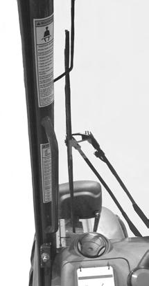
21 SAFETY DECAL LOCATIONS L L70306 L L65928 L L70307 L65932 L PRINTED IN U.S.A /AP0309


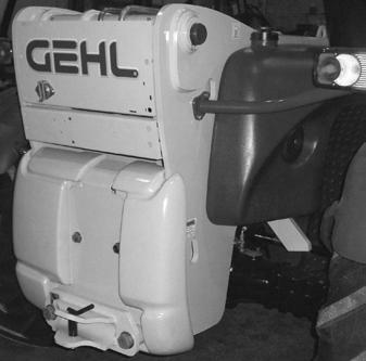
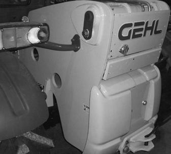
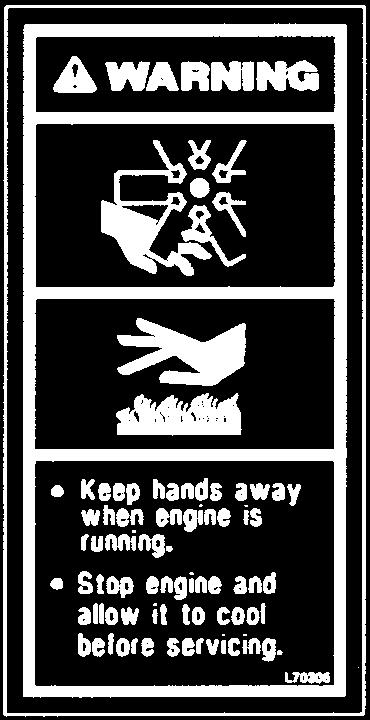
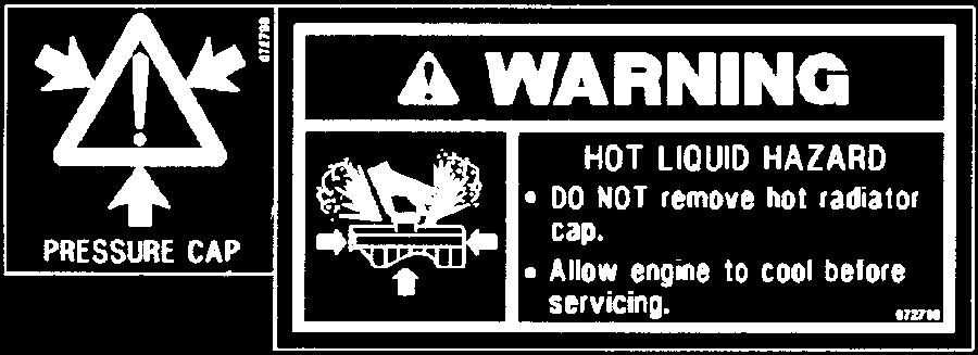
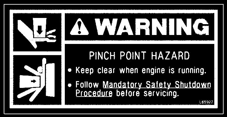
22 SAFETY DECAL LOCATIONS L70305 L L65927 L65927 L65927 L65927 L65927 L L /AP PRINTED IN U.S.A.
23 A - BEFORE STARTING THE TELE- SCOPIC HANDLER Perform daily maintenance (see chapter: 6 - MAINTENANCE: A - DAILY OR EVERY 10 HOURS SERVICE). Make sure the lights, indicators and windshield wipers are working properly. Make sure the rearview mirrors are in good condition, clean and properly adjusted. Make sure the horn works. B - OPERATOR INSTRUCTIONS Whatever his/her experience, the operator is advised to familiarize himself/herself with the location and operation of all the controls and instruments before operating the telescopic handler. Wear clothes suited for operating the telescopic handler. Avoid loose clothing. Make sure you have the appropriate personal protective equipment for the job. Prolonged exposure to high noise levels may cause hearing problems. It is recommended to wear ear muffs to protect against excessive noise. Always keep alert when using the telescopic handler. Do not listen to the radio or music using headphones or earphones. Never operate the telescopic handler when hands or feet are wet or soiled with greasy substances. For increased comfort, ensure that the seat is adjusted to your requirements and in the correct position. If a control is equipped with a locking device, it is forbidden to leave the cab without first locking the control in neutral. Chapter 4 OPERATING AND SAFETY INSTRUCTIONS WARNING DO NOT adjust the seat while the telescopic handler is moving. C - ENVIRONMENT Comply with all work site safety rules. If the telescopic handler must be used in a dark area or at night, make sure it is equipped with working lights. During operation, make sure that no one is in the way of the telescopic handler and its load. Do not allow anybody to come near the work area of the telescopic handler or pass under an elevated load. When using the telescopic handler on a side slope, before lifting the boom, follow the instructions given in the paragraph: INSTRUCTIONS FOR HANDLING A LOAD: M - TRANSVERSE ATTITUDE OF THE TELESCOPIC HANDLER. Travelling on a longitudinal slope: Drive and brake gently. Moving without a load: Forks or attachment facing downhill. Moving with a load: Forks or attachment facing uphill. Never move onto a trailer without having first checked: That it is suitably positioned and made fast. That the unit to which it is connected (wagon, truck, etc.) will not shift. That the trailer is suitable for the total weight of the telescopic handler. That the trailer is suitable for the size of the telescopic handler. Never move onto a bridge, floor or elevator, without being certain that it is suitable for the weight and size of the telescopic handler and without having checked that it is in good condition. Be careful in the area of loading bays, trenches, scaffolding, soft ground and manholes. PRINTED IN U.S.A /AP0309
24 Make sure the ground is stable and firm under the wheels and/or stabilizers before lifting or removing the load. If necessary, add sufficient wedging under the stabilizers, if equipped. Make sure that the scaffolding, loading platform, pilings or ground is capable of bearing the load. Never stack loads on uneven ground, because they may tip over. In the case of work near power lines, ensure that the safety distance is sufficient between the work area of the telescopic handler and the power lines. WARNING You could be electrocuted or seriously injured if you operate or park the telescopic handler too close to power lines. Consult your local utilities. WARNING In the event of high winds, do not perform work that jeopardizes the stability of the telescopic handler and its load, particularly if the load can be affected by the wind. D - VISIBILITY Maintain good visibility throughout the route. In reverse, either look directly behind or use the rearview mirrors. In any case, avoid driving in reverse over long distances. Visibility may be reduced on the right side when the boom is raised, so before lifting the boom make sure that the movement can be made in complete safety. If the forward visibility is not sufficient because of the bulkiness of the load, drive in reverse. This movement must be an exception and only done for short distances. Ensure good visibility (clean windows, adequate lighting, correctly adjusted rearview mirrors, etc.). If visibility of the road is inadequate, ask someone to help, standing outside the area in which the machine will be moving, and making sure you always have a good view of this person. E - STARTING THE TELESCOPIC HANDLER WARNING The telescopic handler must only be started or moved when the operator is sitting in the cab with the seat belt fastened and adjusted. Never try to start the telescopic handler by pushing or towing it. Such operation may cause severe damage to the transmission. If it s necessary to tow the telescopic handler in an emergency, the transmission must be placed in neutral (see chapter: 6 - MAINTENANCE: G - PERIODIC MAINTE- NANCE). Check for closing and locking of covers. Make sure that the forward/reverse lever is in neutral. Turn the ignition key to position I to activate the electrical system. Make sure the signal lights on the instrument panel and fuel level indicators are working properly (see chapter: 5 - INSTRUMENTS AND CONTROLS: 3 - CONTROL AND SIGNAL LAMP PANEL). Turn the ignition key to position II to preheat for 15 seconds and then turn the ignition key fully; the engine should then start. Release the ignition key and let the engine run at idle. Do not engage the starter motor for more than 15 seconds. Carry out the preheating for 10 seconds between unsuccessful attempts. Make sure all the signal lamps on the instrument panel are off. Check all instruments when the engine is warm and at regular intervals during use, to detect any faults and be able to correct them without delay. If an instrument does not show the correct display, stop the engine and immediately carry out the necessary corrections /AP PRINTED IN U.S.A.
25 WARNING The electrolyte in the battery may produce an explosive gas. Avoid open flames and sparks close to the batteries. Never disconnect a battery while it is charging. Failure to ensure proper polarity between batteries can cause serious damage to the electrical circuit. Jump-Starting Procedure If the battery becomes discharged or does not have enough power to start the engine, use jumper cables and the following procedure to jump-start the engine. If using a jumper battery for start-up, use a battery with the same voltage and ensure proper polarity when connecting it. IMPORTANT: BE SURE that the jumper battery is also a 12-volt D. C. battery, and the vehicle used for jump starting has a negative-ground electrical system. WARNING The ONLY safe method for jump-starting a discharged battery is for TWO PEOPLE to perform the following procedure. The second person is needed for removing the jumper cables so that the operator does not have to leave the operator s compartment while the engine is running. NEVER connect the jumper cables directly to the starter solenoid of either engine. DO NOT start the engine from any position other than the operator s seat, and then ONLY after making sure all controls are in neutral. Closely follow the jump-start procedures, in the order listed, to avoid personal injury. In addition, wear safety glasses to protect your eyes, and avoid leaning over the batteries while jump-starting. 1. Turn the keyswitches on both vehicles to OFF. Be sure that both vehicles are in neutral and not touching. 2. Connect one end of the positive (+) jumper cable to the positive (+) battery terminal on the disabled machine first. DO NOT allow the positive (+) jumper cable clamps to touch any metal other than the positive (+) battery terminals. Connect the other end of the positive jumper cable to the jumper battery positive (+) terminal. 3. Connect one end of the negative (-) jumper cable to the jumper battery negative (-) terminal. 4. Make the final negative (-) jumper cable connection to the disabled machine s engine block or frame (ground) - NOT to the disabled battery negative post. If making the connection to the engine, keep the jumper clamp away from the battery, fuel lines, or moving parts. NOTE: Twist the jumper cable clamps on the battery terminals to ensure a good electrical connection. 5. Proceed to start the machine. If it does not start immediately, start the jumper vehicle engine to avoid excessive drain on the booster battery. 6. After the machine is started and running smoothly, have the second person remove the jumper cables (negative (-) jumper cable first) from the jumper vehicle battery, and then from the disabled machine, while ensuring NOT to short the two cables together. Allow sufficient time for the alternator to build up a charge in the battery before operating the machine or shutting off the engine. NOTE: If the battery frequently becomes discharged, have the battery checked for possible dead cells, or troubleshoot the electrical system for possible short circuits or damaged wire insulation. DO NOT attempt to jump-start the machine if the battery is frozen, because this may cause it to rupture or explode. PRINTED IN U.S.A /AP0309
26 F - OPERATING THE TELESCOPIC HANDLER Do not perform operations that exceed the capacities of the telescopic handler or attachments. Always drive the telescopic handler with the forks or attachment in the transport position, i.e., 1 foot (300 mm) from the ground, the boom retracted and the carriage tilted rearward. Only carry loads that are balanced and properly anchored to avoid any risk of a load falling off. Ensure that pallets, cases, banding, etc. are in good condition and suitable for the load to be lifted. Familiarize yourself with the telescopic handler on the terrain where it will be used. Ensure that the service brakes are working properly. The loaded telescopic handler must not travel at speeds in excess of 7 mph (12 km/h). Drive smoothly at an appropriate speed for the operating conditions (terrain, load on the telescopic handler). Do not use the hydraulic boom controls when the telescopic handler is moving. Do not move the telescopic handler with the boom in the raised position unless under exceptional circumstances, and then with extreme caution, at very low speed and using gentle braking. Ensure that visibility is adequate. Drive around turns slowly. WARNING Operators must always consider the risks involved in using the telescopic handler, in particular: - Risk of losing control - Risk of losing side or front stability of the telescopic handler The operator must remain in control of the telescopic handler at all times. In the event of the telescopic handler overturning, do not try to leave the cabin during the incident. THE BEST PROTECTION IS TO STAY IN THE CABIN, AND LEAN AWAY FROM THE FALL. In all circumstances make sure you are in control of your speed. On damp, slippery or uneven terrain, drive slowly, and brake gently, never abruptly. Only use the telescopic handler s forward/reverse lever from a stationary position and never do so abruptly. Do not drive with your foot on the brake pedal or with the parking brake on. Always remember that hydrostatic steering is very sensitive to movement of the steering wheel, so turn it gently and smoothly. Never leave the engine running when the telescopic handler is unattended. Do not leave the cab when the telescopic handler has a raised load. Look where you are going and always make sure you have good visibility along the route. Use the rear-view mirrors frequently. Drive around, not over, obstacles. Never drive along the edge of a ditch or a steep slope. It is hazardous to use two telescopic handlers simultaneously to handle heavy or large loads, because this operation requires particular precautions to be taken. It must only be used when no other option is available and after risk analysis. Engage the gear required (see chapter: 5 - INSTRUMENTS AND CONTROLS: 16 - SHIFT LEVER AND TRANSMISSION CUT-OFF). Select the steering mode appropriate for its use and working conditions. Shift the forward/reverse lever to the selected direction of travel. Release the parking brake and accelerate gradually. G - STOPPING THE TELESCOPIC HANDLER Never leave the ignition key in the telescopic handler during the operator's absence. When the telescopic handler is stationary, or if the operator has to leave the cab (even for a moment), place the forks or attachment on the ground, apply the parking brake and put the forward/reverse lever in neutral /AP PRINTED IN U.S.A.
27 Make sure that the telescopic handler is stopped where it will not interfere with the traffic flow and is at least 3 feet (1 meter) away from any railway tracks. Park the telescopic handler on flat ground or on an incline less than 15 %. Place the forward/reverse lever in neutral. Apply the parking brake. Entirely retract the boom. Lower the forks or attachment to rest on the ground. When using an attachment with a grab or jaws, or a bucket with hydraulic opening, close the attachment fully. Before stopping the telescopic handler after a long working period, let the engine idle for a few minutes, to allow the coolant and oil to lower the temperature of the engine and transmission. Do not neglect this precaution in the event of frequent stops or stalling of the engine, or else the temperature of certain parts will rise significantly due to the stopping of the cooling system, with the risk of badly damaging such parts. Stop the engine with the ignition switch. Remove the ignition key. Make sure all means of access to the telescopic handler are closed and locked (doors, windows, engine cover ). In the event of prolonged parking on a site, protect the telescopic handler from bad weather, particularly from freezing (check the level of antifreeze). H - DRIVING THE TELESCOPIC HAN- DLER ON A PUBLIC HIGHWAY Operators driving on a public highway must comply with highway regulations. The telescopic handler must also comply with highway regulations. If necessary, contact your dealer. If equipped, make sure the rotating beacon is in place. Switch it on and verify its operation. Check for good working order and cleanliness of lights, indicators and windshield wipers. Switch off the working lights if the telescopic handler is so equipped. Select the steering mode for "HIGHWAY TRAF- FIC" (see chapter: 5 - INSTRUMENTS AND CONTROLS: 19 - STEERING MODE SELEC- TION). Entirely retract the boom and position the attachment approximately 1 foot (300 mm) from the ground. On the road, start off in 3rd gear and shift into 4th when the conditions allow. In hilly areas, start off in 2nd gear and shift into 3rd when the conditions allow. WARNING Never coast in neutral (forward/reverse lever in neutral or transmission cut-off button pressed) to avoid the effects of engine braking. Failure to follow this warning on a slope will lead to excessive speed, which may make the telescopic handler uncontrollable (steering, brakes) and may cause an accident or severe mechanical damage. I - DRIVING THE TELESCOPIC HAN- DLER WITH A FRONT-MOUNTED ATTACHMENT You must comply with regulations in your state/province. The attachment must not be loaded. Make sure that the attachment does not block the forward lights. J - OPERATING THE TELESCOPIC HANDLER WITH A TRAILER For using a trailer, observe the regulations in force in your state/province (maximum travel speed, braking, maximum weight of trailer, etc.). Do not forget to connect the trailer s electrical equipment to that of the telescopic handler if equipped. The trailer's braking system must comply with regulations. When pulling a trailer with brakes, the telescopic handler must be equipped with a trailer brake control. In this case, remember to connect the trailer brake equipment to the telescopic handler. The maximum vertical load on the trailer hook must not exceed 3372 lbs. (1530 kg). PRINTED IN U.S.A /AP0309
28 The authorized maximum trailer weight must not exceed the maximum weight authorized by the manufacturer (consult the manufacturer s plate on the telescopic handler). When driving with a trailer, start off in 2nd gear and shift into 3rd when the conditions and condition of the road allow. Do not use 4th gear, to avoid overheating the engine and transmission. IF NEC- ESSARY, CONSULT YOUR DEALER. INSTRUCTIONS FOR HANDLING A LOAD K - CHOICE OF ATTACHMENTS Only attachments approved by GEHL can be used on GEHL telescopic handlers. Make sure the attachment is appropriate for the work to be done (see chapter: 7 - ATTACH- MENTS). Make sure the attachment is correctly installed and locked onto the carriage. Make sure that the attachments work properly. Comply with the load chart limits for the attachment used. Do not exceed the rated capacity of the attachment. Never lift a load in a sling without the proper attachment for the purpose. L - MASS AND CENTER-OF-GRAVITY OF LOAD Before picking up a load, you must know its weight and its center-of-gravity. The load chart for your telescopic handler is valid for a load in which the longitudinal position of the load center is 24 (610 mm) forward of the base of the forks (fig. L1). For different load centers, contact your dealer. For irregular loads, determine the side to side center-of-gravity before any movement (fig. L2) and set it on the longitudinal axis of the telescopic handler. WARNING DO NOT move a load heavier than the telescopic handler s rated capacity as listed on the load charts. WARNING For loads with a moving center-of-gravity (e.g., liquids), take into account the movement of the center-of-gravity to determine the load that can be safely handled. Be vigilant and take extra care to limit these movements as much as possible. M - TRANSVERSE ATTITUDE OF THE TELESCOPIC HANDLER The transverse (side-to-side) attitude is the angle of the chassis with respect to horizontal. Raising the boom reduces the telescopic handler's lateral stability. Position the telescopic handler so that the bubble in the inclinometer is between the two lines (see chapter: 5 - INSTRUMENTS AND CONTROLS: 35 - INCLINOMETER) /AP PRINTED IN U.S.A.
29 Grade and Slope Precautions The Telescopic Handler complies with industry stability test requirements and is stable when properly operated. However, improper operation, faulty maintenance, and poor housekeeping can contribute to a condition of instability and defeat the purpose of the standard. The amount of forward and rearward tilt to be used is governed by the application. Although use of maximum rearward tilt is allowable under certain conditions, such as traveling with the load fully lowered, the stability limits of the machine, as determined by the industry standard tests, do not encompass consideration for excessive tilt at high elevations, or the handling of off-center loads. Only handle loads within the capacity limits of the machine, and which are stable and safely arranged. When attachments are used, extra care should be taken in securing, manipulating, positioning and transporting the load. Grade Limits NOTE: Grade limits are based on ANSI/ITSDF standard B This Telescopic Handler meets or exceeds the safety standard (ANSI/ITSDF B56.6) stability limits for rough terrain forklifts. The stability tipping limits cover specific, controlled test conditions, which are extremes, and which are not intended to be achieved during normal worksite operations. The following specifications are provided only as information to the operator, and must not be used as a guideline for operating the Telescopic Handler. For safe operation, always follow the instructions and warnings provided in this manual. 1. DO NOT place or retrieve loads on an up or down slope or grade that exceeds 7% or DO NOT travel up or down a grade or slope that exceeds 22% or 12 while loaded. 3. DO NOT place or retrieve loads on a side hill with a slope or grade that exceeds 12% or 7. Check the location of the ball in the frame angle indicator located on the ROPS/FOPS cross member. If the ball in the frame angle indicator is in the green zone, it is safe to place or retrieve the load. If the ball in the frame angle indicator is in the yellow zone, use slower movements and extra caution to ensure remaining within the limits of the load chart, because the machine is nearing an unstable condition. If the ball in the frame angle indicator is in the red zone, loads cannot be placed or retrieved. 4. DO NOT travel across a side hill that exceeds 18% or 10 grade. Check the frame angle indicator on the ROPS/FOPS cross member to determine the angle of the grade. The attachment tool MUST be maintained at the carry position, with the boom fully retracted and attachment tool at minimum ground clearance. When ascending or descending grades in excess of 5% or 3, the machine should be driven with the load upgrade. An unloaded machine should be operated on all grades with the load handling attachment tool downgrade, tilted back if applicable, and raised only as far as necessary to clear the ground surface. Avoid turning if possible and use extreme caution on grades, ramps and inclines. Normally travel straight up and down the slope. PRINTED IN U.S.A /AP0309

. Adjust the fork spread and centering to best connect with the load (fig. N2).")
 and bring the forks to stop in front of the load (fig. N3).")
30 Traffic Flow Patterns Know and understand the traffic flow patterns of your jobsite. Know all Telescopic Handler hand signals for safety. Use signal persons as necessary for safe operation, and be sure you can see the signal person and acknowledge the signals given. N - PICKING UP A LOAD ON THE GROUND Approach the load with the telescopic handler perpendicular to the load, with the boom retracted and the forks in a horizontal position (fig. N1). Adjust the fork spread and centering to best connect with the load (fig. N2). WARNING Beware of the risks of trapping or pinching limbs when manually adjusting the forks. Never lift a load on a single fork. Move the telescopic handler forward slowly (1) and bring the forks to stop in front of the load (fig. N3). If necessary, slightly lift the boom (2) while picking up the load. Bring the load into the transport position. Safety Hand Signals Tilt the load back far enough to ensure stability (loss of load while braking or going downhill) /AP PRINTED IN U.S.A.
31 Always think about keeping the distance necessary to fit the forks under the load between the pile and the telescopic handler (fig. O1) and use the shortest possible extension of the boom. FOR A NON-PALLETIZED LOAD: Tilt the carriage (1) forward and move the telescopic handler slowly forward (2), to insert the forks under the load (fig. N4) (block the load if necessary). Continue to move the telescopic handler forward (2) tilting the carriage (3) (fig. N4) rearward to position the load on the forks and check the load's longitudinal and lateral stability. Stop the forks in front of the load by alternately raising and extending the boom (1) or, if necessary, moving the telescopic handler forward (2) (fig. O2). Apply the parking brake and shift the transmission into neutral. O - PICKING UP A HIGH LOAD WARNING DO NOT raise the boom until you have verified the side-to-side attitude of the telescopic handler. Make sure that the following operations can be performed with good visibility. Slightly lift the load (1) and tilt the carriage (2) rearward to stabilize the load (fig. O3). Ensure that the forks will easily pass under the load. Lift and extend the boom (1) (2) until the forks are level with the load, moving the telescopic handler (3) forward if necessary (fig. O1), moving very slowly and carefully. Tilt the load sufficiently rearward to ensure its stability. PRINTED IN U.S.A /AP0309
32 If possible lower the load without moving the telescopic handler. Lift the boom (1) to release the load, retract (2) and lower the boom (3) to bring the load into the transport position (fig. O4). Lift and extend the boom (1) (2) until the load is above the stack. If necessary, move the telescopic handler (3) forward (fig. P7), driving very slowly and carefully. If this is not possible, back up the telescopic handler (1), maneuvering very gently and carefully to release the load. Retract (2) and lower the boom (3) to bring the load into the transport position (fig. O5). Place the load in a horizontal position and set it down on the stack by lowering and retracting the boom (1) (2) to position the load correctly (fig. P8). P - SETTING DOWN A HIGH LOAD Approach with the load in the transport position in front of the stack (fig. P6). If possible, release the fork by alternately retracting and raising the boom (1) (fig. P9). Then return the forks to transport position. Apply the parking brake and set the forward/reverse lever in neutral /AP PRINTED IN U.S.A.
33 If this is not possible, reverse the telescopic handler (1) very slowly and carefully to release the forks (fig. P10). Then return the forks to transport position. Q - SUSPENDED LOADS The handling of suspended loads by means of the truss boom or other similar device can introduce dynamic forces affecting the stability of the machine that are not considered in the stability criteria of industry test standards. Grades, sudden starts, stops and turns can cause the load to swing and create a hazard. DO NOT exceed the Telescopic Handler capacity for handling suspended loads. Only lift the load vertically; NEVER drag it horizontally. Use tag lines to restrain load swing whenever possible. GUIDELINES FOR FREE RIGGING/ SUSPENDED LOADS 1. The rigging equipment must be in good condition and comply with the applicable U.S. OSHA regulation, , Slings, or , Rigging equipment for material handling. 2. The rigging equipment must be secured to the forks such that it cannot slip or slide either sideways or fore and aft. 3. The capacity of the fork(s) and the machine (whichever is less) must not be exceeded. 4. The load center must remain at 24 (610 mm) or less. 5. No lifting of material may be done when anyone is on the load, rigging or forks. 6. Multiple pickup points on the load are preferred to prevent the load from rotating, but a single pickup point may be used if one or more tag lines are utilized. And, of course, the load must never be positioned over personnel at any time. PRINTED IN U.S.A /AP0309
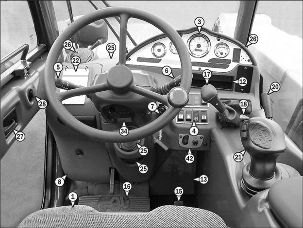
34 Chapter 5 INSTRUMENTS AND CONTROLS /AP PRINTED IN U.S.A.
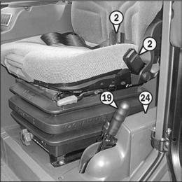
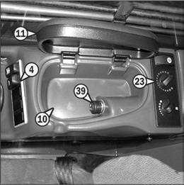
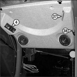
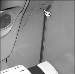
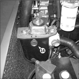
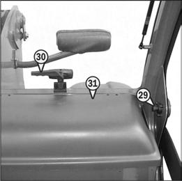
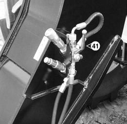
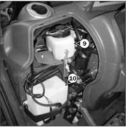
35 DESCRIPTION 1 - Operator s Seat 2 - Seat Belt 3 - Control and Signal Lamp Panel 4 - Switch Panels 5 - Light Switch, Horn and Turn Indicator Switch 6 - Front and Rear Windshield Wiper Switch 7 - Ignition Switch 8 - Brake Fluid Reservoir and Windshield Washer Reservior Access Panel 9 - Brake Fluid Reservoir 10 - Windshield Washer Reservoir 11 - Armrest and Storage 12 - Storage Tray (Optional Radio) 13 - Fuse and Relay in the Cab 14 - Fuses and Relays under the Engine Cover 15 - Accelerator Pedal 16 - Service Brake and Transmission Cutoff Pedal 17 - Shift Lever and Transmission Cutoff 18 - Forward / Neutral / Reverse Switch 19 - Parking Brake Lever 20 - Steering Mode Selector Lever 21 - Hydraulic Controls and Transmission Cutoff* 22 - Function Controls / Load Charts 23 - Air Conditioner / Heater Controls 24 - Cab Air Filter 25 - Windshield Defroster Vents 26 - Heating Vents 27 - Door Lock 28 - Lock Handle for Upper Half Door 29 - Release Button for Upper Half Door 30 - Handle for Rear Window Opening 31 - Manual Holder 32 - Front Lights 33 - Rear Lights 34 - Steering Wheel Position Adjustment Handle 35 - Inclinometer 36 - Sun Visor (Roof and Windshield) 37 - Cab Interior Light 38 - Clothes Hook 39 - Cigar Lighter and 12-VDC Accessory Outlet 40 - Engine Block Heater 41 - Hydraulic Attachment Locking 42 - Attachment Hydraulic Control for Continous Operation and Flow Control TOW PIN (Not shown on page 32. See page 48). A - Tow Pin B - Trailer Electric Connector OPTIONS (Not shown on page 32. See page 49). 1 - Boom Ride Control 2 - Reversible Fan 3 - Second Auxiliary Hydraulic Circuit with Hydraulic Attachment Locking 4 - Boom Mounted Work Lights 5 - Windshield Protection Grill 6 - AM/FM Radio 7 -Rear Window De-icing * NOTE: If the hydraulic functions do not operate, turn the steering wheel to recharge the hydraulic control accumulator and hydraulic functions should be restored. PRINTED IN U.S.A /AP0309
36 NOTE: All terms such as: RIGHT, LEFT, FRONT, REAR are meant for an observer seated in the operator s seat and looking forward. 1 - OPERATOR S SEAT Designed for maximum comfort, this seat can be adjusted as follows: WEIGHT ADJUSTMENT (FIG. A) It is recommended that the weight be adjusted when the operator is not sitting in the seat. FORE AND AFT ADJUSTMENT (FIG. D) The depth of the seat may be adjusted to suit the individual Refer to graduation (1) of the seat. - Turn handle (2) depending on the operator s weight. NOTE: It is recommended that the weight should be checked and adjusted before starting the telescopic handler. - Press the right-hand button while moving the seat to find the desired position. EXTENDING THE HEADREST (FIG. E) HEIGHT ADJUSTMENT (FIG. B) Raise the seat to the desired position, until the ratchet clicks. If the seat is raised above the last notch (stop), the seat drops down to the lowest position. SEAT CUSHION ANGLE ADJUSTMENT (FIG. C) The angle of the seat cushion may be adjusted to suit the individual. - Press the left-hand button while pushing on the seat or relaxing pressure on the seat to find a comfortable position. - The height of the headrest can be adjusted by pulling it upwards (the notches will click) up to the stop. - The headrest can be removed by applying sufficient force to pull it off the stop. LUMBAR ADJUSTMENT (FIG. F) /AP PRINTED IN U.S.A.
37 This increases the comfort of the seat and the operator s freedom of movement. - Turn the handle either left or right to adjust the height or depth of the lumbar support. ANGLE ADJUSTMENT OF THE BACKREST (FIG. G) MAINTENANCE (FIG. I) - Support the backrest, pull the lever and position the backrest to find the desired position. WARNING Support the backrest when making adjustments to prevent it from swinging completely forward. LONGITUDINAL ADJUSTMENT (FIG. H) Dirt may adversely affect the correct functioning of the seat. For this reason, make sure the seat is always clean. - To clean or change the cushions, simply remove them from the seat frame. Avoid getting the cushion fabric wet when cleaning. Check the color-fastness of the fabric on a small hidden area before using any fabric or vinyl cleaner. 2 - SEAT BELT WARNING Do not use the telescopic handler if the seat belt is damaged (not latching, cuts, tears, etc.). Repair or replace the seat belt immediately. - Adjust the locking lever until you reach the position required. This then locks and the seat will not shift into another position. - Sit properly on the seat. - Check that seat belt is not twisted. - Place the seat belt at hip level. - Attach the seat belt and check that it latches. - Adjust the seat belt to your body shape, without squeezing your hips and without excess slack. PRINTED IN U.S.A /AP0309
 Use the telescopic handler normally.")
 Stop the telescopic handler, look for the cause of the engine overheating. NOTE: Red indicator lamp K comes on between zone A3 and A4.")
38 N O M P E G I K F H J L 3 - CONTROL AND SIGNAL LAMP PANEL INSTRUMENTS A - ENGINE COOLANT TEMPERATURE Temperature zones: A1 - Blue zone: F (0-50 C) Use the telescopic handler under a light load until the temperature reaches the green zone. A2 - Green zone: F ( C) Use the telescopic handler normally. A3 - White/red zone: F ( C) Use the telescopic handler moderately and monitor the temperature. A4 - Red zone: F ( C) Stop the telescopic handler, look for the cause of the engine overheating. NOTE: Red indicator lamp K comes on between zone A3 and A4. B - HOURMETER AND TACHOMETER C - FUEL LEVEL Red zone (C1) indicates that the reserve fuel supply is being used and that engine run time is limited. D - CLOCK Indicates the time of the day. Time is adjusted by pressing and holding one of the two small buttons located in the face of the clock. The right button adjusts the time forward and the left button adjusts the time backwards. SIGNAL LAMPS When activating the electrical system of the telescopic handler, all the red and orange lamps must light and the panel's buzzer must sound to indicate their good working order. If one of the red lamps or the buzzer does not function, carry out the necessary repairs. WARNING A permanently lit or flashing warning lamp, with the engine running, indicates an operating fault. The lighting of some lamps may be accompanied by an audible signal. Do not ignore this warning, contact your dealer without delay. If one of the warning lamps comes on while the telescopic handler is in motion, stop the telescopic handler under the safest possible conditions. Contact your Gehl Telescopic Handler dealer to diagnose the cause of the malfunction. E - RED TRANSMISSION OIL SURE LAMP PRES- The lamp and the buzzer come on when the pressure in the transmission, when driving forward, is abnormally low. Stop the telescopic handler and look for the cause (insufficient transmission oil level, internal leak in the transmission, etc.). NOTE: The signal lamp operates in forward travel conditions only. The signal should not be taken into account when the engine is running at idle or is stopped. F - RED TRANSMISSION OIL TEMPER- ATURE LAMP The lamp and the buzzer come on when the torque converter oil temperature is abnormally high. Stop the telescopic handler and look for the cause of this overheating /AP PRINTED IN U.S.A.

39 G - RED BRAKE FLUID LEVEL LAMP If the lamp and the buzzer come on when the telescopic handler is running, stop the engine immediately and check the brake fluid level. In the event of an abnormal dropping of the fluid level, consult your dealer. H - RED PARKING BRAKE LAMP This lamp comes on when the parking brake is applied. 4 - SWITCH PANELS NOTE: The location of the switches may vary depending on the options. I - RED ALTERNATOR CHARGE LAMP If the lamp and the buzzer come on when the telescopic handler is running, stop the engine immediately and check the electrical circuit and the alternator belt. J - RED ENGINE OIL PRESSURE LAMP If the lamp and the buzzer come on when the telescopic handler is running, stop the engine immediately and look for the cause (check oil level in engine crankcase). K - RED ENGINE COOLANT TEMPERA- TURE LAMP If the lamp and the buzzer come on when the telescopic handler is running, stop the engine immediately and investigate the cooling system for the cause of the malfunction. L - RED LAMP - AIR FILTER OR HYDRAULIC RETURN FILTER CLOGGED The lamp and buzzer come on when the air filter cartridge or the hydraulic return oil filter cartridge is clogged. Stop the telescopic handler and carry out the necessary repairs (see cleaning and replacement requirements in chapter 6 - MAINTE- NANCE: FILTER CARTRIDGES AND BELTS). M - GREEN TURN INDICATOR LAMP This lamp will be lighted when the turn indicators are on. N - GREEN SIDELIGHTS LAMP This lamp will be lighted when the sidelights are on. O - GREEN LOW BEAM LAMP This lamp will be lighted when the low beam lights are on. P - BLUE MAIN BEAM LAMP This lamp will be lighted when the main beam lights are on. A - OPTION B - OPTION C - WHEEL ALIGNMENT LAMPS These lamps will light when the front and rear wheels are in the straight-ahead position. D - WARNING LIGHTS This switch enables the left and right turn indicators to be switched on simultaneously, with the ignition off, for use as a hazard indicator. The signal lamp indicates that the switch is being used. E - REAR FOG LIGHT This switch lights the fog lights on the rear of the machine. The head lights must be on before this switch can be activated. Pressing the bottom of the switch turns ON the rear fog lights. F - REVERSIBLE FAN (OPTION) This switch activates the reversible fan to clean the radiator core and engine cover grill. The lamp in the switch will be on when the switch is activated. G - STEERING SELECTION H - TRANSMISSION CUT-OFF The switch selects transmission cut-off feature to either the service brake pedal or the joystick control lever. Position 1: Indicator lamp on, transmission cut-off to service brake pedal enabled. Position 2: Indicator lamp off, transmission is cut-off from forward/neutral/reverse gear selector. USE OF TRANSMISSION CUT-OFF Transmission cut-off to brake pedal (position 1): When loading. PRINTED IN U.S.A /AP0309


 This switch activates the boom ride control to reduce abrupt movement of the telescopic handler on rough ground.")
40 Transmission cut-off to hydraulic control lever (position 2): When driving; For inching and continuous stopping and starting (delicate handling). In order to optimize hydraulic movements, cut off transmission to the hydraulic controls lever; Starting on a slope. NOTE: In all cases, transmission cut-off can be effected by using the shift lever. M - SIDE WINDOW WIPER AND ROOF WINDOW WIPER Pressing the top of the switch activates the roof window wiper. Pressing and holding the bottom of the switch activates the side window wiper. I - OPTION J - FRONT AND REAR WORK LIGHTS Pressing the top of this switch turns ON the front and rear work lights. Pressing the bottom of this switch turns ON the front work lights. The center position of the switch turns the front and rear work lights OFF. The signal lamp in the switch will be ON when the switch is activated. K - BOOM-MOUNTED WORK LIGHTS, OPTION This switch lights the work lights mounted at the end of the boom. Pressing the bottom of the switch turns ON the boom work lights. N - OPTION O - OPTION P - ATTACHMENT HYDRAULIC LOCKING DEVICE See chapter: 7 - ATTACHMENTS: INSTALLING ATTACHMENTS. Q - BOOM RIDE CONTROL (OPTION) This switch activates the boom ride control to reduce abrupt movement of the telescopic handler on rough ground. The lamp in the switch will be on when the switch is activated. R - JOYSTICK LOCKOUT When activated, this switch disables the joystick hydraulic functions. The lamp in the switch will be on when the switch is activated. This switch should be activated for road travel. 5 - LIGHT SWITCH, HORN AND TURN INDICATOR SWITCH L - REAR WINDOW DEFROSTING, OPTION This switch activates the heating element in the rear window. The switch controls the visual and audible alarms /AP PRINTED IN U.S.A.


41 A - All lights are off; the direction indicators do not flash. B - The right turn indicators flash. C - The left turn indicators flash. D - The sidelights and the rear lights are on. E - The low-beam headlights and the rear lights are on. F - The high-beam headlights and the rear lights are on. G - Flashes high-beam headlights when held in this position. Pressing the end of the switch sounds the horn. NOTE: The positions D - E - F - G can be used without the ignition being on. 6 - FRONT AND REAR WINDSHIELD WIPER SWITCH I - Ignition on II - Pre-heating III - Start P O I When the engine starts, the key returns to position I as soon as it is released. 8 - BRAKE FLUID RESERVOIR AND WINDSHIELD WASHER RESERVOIR ACCESS PANEL II III The switch controls the operation of the front and rearwindshield wipers. A - Front windshield wiper off B - Front windshield wiper low speed setting C - Front windshield wiper high speed setting D - Front windshield washer E - Rear windshield wiper off F - Rear windshield wiper on NOTE: These functions will only operate when the ignition switch is on. - Loosen screw (1) and lift up the brake fluid and windshield washer access panel. 9 - BRAKE FLUID RESERVOIR See chapter: 6 - MAINTENANCE: B - EVERY 50 HOURS SERVICE WINDSHIELD WASHER RESERVOIR See chapter: 6 - MAINTENANCE: B - EVERY 50 HOURS SERVICE. 7 - IGNITION SWITCH The key switch has five positions: P - Ignition off, parking position O - Ignition switched off and engine stopped PRINTED IN U.S.A /AP0309
.")
 - Working tail light (10A) - Rear windscreen wiper (7.")
 F5 - OPTION F6 - Wheel alignment (5A) F7 - OPTION F8 - Forward/neutral/reverse selector (15A) - Transmission cut-off (15A) - Reverse lights (15A) - Backup alarm (15A) F9 - Control panel (5A) F10")
 F17 - Attachment hydraulic locking device - Reversible fan (10A) - Electric valve on boom and reversible fan (15A) F18 - Front working light (15A) F19 - OPTION Rear window defrosting (15A) F20 -")
42 11 - ARMREST AND STORAGE - Lift the armrest (1) to access the storage area STORAGE TRAY - RADIO (OPTION) Radio option shown in place of the storage tray. Review the radio manual provided with your machine for radio operation controls FUSES AND RELAYS IN THE CAB - Lift up the fuse and relay access panel (1). A sticker on the inside of the access panel gives a clear display of the use of the components described below. IMPORTANT: Replace a failed fuse with a new fuse of the same quality and capacity. Never use a repaired fuse. F1 F2 F3 - Attachment hydraulic locking device (7.5A) - Working tail light (10A) - Rear windscreen wiper (7.5A) - Side windscreen wiper + Roof windscreen wiper (10A) F4 - Engine shut-off solenoid (7.5A) F5 - OPTION F6 - Wheel alignment (5A) F7 - OPTION F8 - Forward/neutral/reverse selector (15A) - Transmission cut-off (15A) - Reverse lights (15A) - Backup alarm (15A) F9 - Control panel (5A) F10 - Backup alarm (15A) - Stop switch (15A) F11 - Boom work lights (10A) F12 - Indicator power supply (10A) F13 - Heating (30A) F14 - Cigar lighter (10A) F15 - OPTION F16 - Air conditioner (7.5A) F17 - Attachment hydraulic locking device - Reversible fan (10A) - Electric valve on boom and reversible fan (15A) F18 - Front working light (15A) F19 - OPTION Rear window defrosting (15A) F20 - OPTION F21 - Front windshield wiper and windshield washer (10A) F22 - Optional boom ride control (10A) F23 - Right sidelight (7.5A) - Sidelight indicator lamp (7.5A) - Control panel lighting (7.5A) F24 - Left sidelights (7.5A) /AP PRINTED IN U.S.A.
 F27 - Low beam (15A) - Low beam indicator lamp (15A) - Rear fog light (15A) F28 - High beam (15A) - High beam indicator lamp (15A) F29 - Hazard warning")
 - OPTION Attachment hydraulic control forced operation (5A) - Remove the covers 2 and 3 for the hydraulic control for access to")


43 F25 - Right turn indicators (7.5A) F26 - Left turn indicators (7.5A) F27 - Low beam (15A) - Low beam indicator lamp (15A) - Rear fog light (15A) F28 - High beam (15A) - High beam indicator lamp (15A) F29 - Hazard warning lights (15A) - Roof light (15A) F30 - Lights, horn and indicator switch (25A) F31 - Starter (20A) F32 - Electroproportional hydraulic control modules (3A) - OPTION Boom suspension (5A) - OPTION Attachment hydraulic control forced operation (5A) - Remove the covers 2 and 3 for the hydraulic control for access to relays. K10 - Optional boom ride control K11 - Boom ride control. K12 - OPTION K0 - Air conditioning K1 - Relay transmission cut-off to hydraulic controls K2 - Transmission cut-off relay K3 - Reverse gear relay K4 - Forward gear relay K5 - Buzzer K6 - Electric valve on boom. - Electric valve on boom head + attachment hydraulic locking device K7 - OPTION K8 - Safety system starting switch relay K9 - Flashing unit K15 - Relay cutting power supply to proportional hydraulic controls 14 - FUSES AND RELAYS UNDER THE ENGINE COVER Remove casing 1 and cover 2 for access to fuses and relays. IMPORTANT: Replace a failed fuse with a new fuse of the same quality and capacity. Never use a repaired fuse. PRINTED IN U.S.A /AP0309


 on the shift lever.")
44 F40 - Telescopic handler electrical equipment (40A) F41 - Telescopic handler electrical equipment (40A) F42 - Preheating engine (80A) F43 - Alternator (80A) K16 - Engine preheating relay 15 - ACCELERATOR PEDAL 16 - SERVICE BRAKE AND TRANSMIS- SION CUTOFF PEDAL Pressing the brake pedal hydraulically activates the internal braking mechanism in the front and rear axles. Depending on the position of the transmission cut-off switch, power to the transmission is cut off. This allows greater engine acceleration and power to the hydraulic system without power to the drive axles while the service brake pedal is depressed. (see: chapter 5 - INSTRUMENTS AND CONTROLS: 5 - SWITCH PANEL) SHIFT LEVER AND TRANSMISSION CUTOFF To shift gears, it is necessary to cut off the transmission by pressing the button (1) on the shift lever. 1st gear: To the right, rearward 2nd gear: To the right, forward 3rd gear: To the left, rearward 4th gear: To the left, forward SHIFTING THE TRANSMISSION Because this telescopic handler has a torque converter, it is not necessary to always start up in 1st gear and progress up through the gears. IMPORTANT: The choice of transmission gear should be made carefully according to the nature of the work being carried out. A poor choice may result in an extremely rapid elevation of the transmission oil temperature through excessive slipping of the converter, which could lead to serious damage to the transmission. (It is essential to stop and change the working conditions if the transmission oil temperature indicator light comes on.) This poor choice may also result in a reduction in the telescopic handler's performance in forward speed. When the forward force increases, the forward speed in the chosen gear (for example, 3rd gear) may be lower than the forward speed that could be obtained with a lower gear (in 2nd instead of the 3rd). In general, use the following gears according to the nature of the work being carried out: On the road: Start off in 3rd gear and shift up to 4th if the conditions permit. In hilly areas: Start off in 2nd gear and shift up to 3rd if the conditions permit. With a trailer on the road: Start off in 2nd gear and shift up to 3rd if the conditions permit. Material handling: Start in 3rd gear, or 2nd gear in restricted spaces. Earthmoving: Start in 1st gear. Loading (with bucket, manure fork, etc.): Start in 2nd gear FORWARD/NEUTRAL/REVERSE SWITCH This switch is used to change the direction of travel (forward or reverse) /AP PRINTED IN U.S.A.
. REVERSE: Pull the switch rearward (position B). NEUTRAL: To start the telescopic handler, the switch must be in the intermediate position (position C).")

45 NOTE: To prevent damage to the transmission, the telescopic handler should be traveling at a slow speed and not accelerating when changing the direction of travel. FORWARD: Push the switch forward (position A). REVERSE: Pull the switch rearward (position B). NEUTRAL: To start the telescopic handler, the switch must be in the intermediate position (position C). NOTE: The reverse lights and the backup alarm indicate that the telescopic handler is operating in reverse. PROCEDURE TO MOVE THE TELESCOPIC HAN- DLER The telescopic handler is equipped with an electronic unit that prevents the machine from moving unless the operator is seated in the seat. To move the telescopic handler, the following sequence must be followed: 1 - sit in the operator s seat, 2 - release the parking brake, and 3 - shift into forward or reverse. To stop the telescopic handler, the following sequence must be followed: 1 - shift into neutral, 2 - apply the parking brake, and 3 - step out of the telescopic handler. If this sequence is not followed (for example, leaving the operator s seat without applying the parking brake), an alarm will sound. The operator must then shift into neutral and follow the sequence PARKING BRAKE LEVER To prevent inadvertent release, the lever is fitted with a safety lock. - To apply the parking brake, pull the lever rearward (position A). - To release the parking brake, release the safety lock and push the lever forward (position B) STEERING MODE SELECTOR LEVER Before selecting one of the three steering modes, bring the four wheels into alignment, i.e., in the straightahead position. A - GREEN LAMPS FOR ALIGNMENT OF THE WHEELS These lamps come on to indicate the alignment of the wheels in relation to the axles of the telescopic handler. The lamp (A1) is for the front wheels, and the lamp (A2) is for the rear wheels. B - STEERING SELECTOR LEVER PRINTED IN U.S.A /AP0309

. - Shift the hydraulic valve control lever for steering selection (B) to position (B2) (4-wheel steering).")
 is ON.")

46 B1 - Front-wheel steer (highway traffic) B2 - Front and rear wheels steer in oppo site directions (4-wheel steer) B3 - Front and rear wheels steer in the same direction (crab steer) NOTE: If the hydraulic functions do not operate, turn the steering wheel to recharge the hydraulic control accumulator and hydraulic functions should be restored. C - SWITCH FOR ALIGNMENT OF THE WHEELS This switch activated indicator lamps A1 and A2 to aid in the alignment of the front and rear wheels. The indicator lamp in the switch indicates if it is ON. WHEEL ALIGNMENT PROCEDURE - Press the switch (signal lamp ON). - Shift the hydraulic valve control lever for steering selection (B) to position (B2) (4-wheel steering). - Turn the steering wheel and bring the rear wheels into alignment until the lamp (A2) is ON. - Shift the hydraulic valve control lever for steering selection (B) to position (B1) (highway use). - Turn the steering wheel and bring the front wheels into alignment until the lamp (A1) is ON. WARNING Before driving on roads, it is necessary to check the alignment of the rear wheels and to select front-wheel steering mode. The alignment of the rear wheels must be done regularly while driving the telescopic handler, with the help of the green lamps. In case of problems, consult your dealer HYDRAULIC CONTROLS AND TRANSMISSION CUTOFF IMPORTANT: Do not attempt to alter the hydraulic system pressure by adjusting the pressure regulating valve. In the event of suspected malfunction, contact your dealer. ANY ALTER- ATION MAY VOID THE WARRANTY. A - Boom lift and attachment tilt control lever. B - Boom extend/retract control button. C - Attachment control button. D - Electric valve on boom control button option. LIFTING THE LOAD - Pull the lever (A) rearward for lifting. - Push the lever (A) forward for lowering. TILTING THE CARRIAGE - Move the lever (A) to the left for rearward tilt. - Move the lever (A) to the right for forward tilt. TELESCOPING THE BOOM - Push the button (B) forward to extend the boom. - Pull the button (B) rearward to retract the boom. ATTACHMENT - Move the button (C) forward or rearward. BOOM NOSE ELECTRICAL VALVE- Button D (see chapter: 5 - DESCRIPTION: DESCRIPTION ELEC- TRICAL AND HYDRAULIC) FUNCTION CONTROLS / LOAD CHARTS WARNING Use the hydraulic controls carefully without jerking, to avoid accidents caused by sudden movement of the telescopic handler /AP PRINTED IN U.S.A.


47 These charts include the description of the hydraulic controls and the load charts for the attachments used on the telescopic handler AIR CONDITIONER / HEATER CON- TROLS IMPORTANT: The air conditioner only comes on when the telescopic handler has been started. When using the air conditioning, the doors and windows should be kept closed. In winter: To ensure proper operation and complete efficiency of the air conditioning unit, switch on the compressor once a week, if only briefly, to lubricate the internal seals. In cold weather: Warm the engine before switching on the compressor, to allow any refrigerant that has collected in the liquid state at the lowest point of the compressor circuit to turn into gas under the effect of the heat given off by the engine, because the compressor is liable to be damaged by liquid refrigerant. IMPORTANT: If the air conditioning does not seem to be working properly, have it examined by your dealer (see chapter: 6 - MAINTENANCE: H - EVERY TWO YEARS). Never try to repair any problems yourself. DESCRIPTION OF THE AIR CONDITION- ING CONTROLS A - Air conditioning system ON/OFF control switch with indicator lamp. Only works when control switch "C" is set to 1, 2 or 3. B - Air temperature control. C - Air flow setting and fan speed control. In position "0" the air conditioning system no longer functions. NOTE: Possible losses of water under the telescopic handler are due to condensation discharges caused by the drying effect of the air conditioning, especially with high outside temperatures and high relative humidity. For the air conditioning to perform properly, the air intakes must not be blocked. When the air conditioner is running, at least one of the cab air vents must be open to avoid the risk of freezing the evaporator. HEATING MODE The controls must be adjusted in the following way: A - Switch with signal lamp off, B - At the selected temperature, and C - At the selected fan speed 1, 2 or 3. AIR CONDITIONING MODE The controls must be adjusted in the following way: A - Switch with signal lamp on, B - At the selected temperature, and C - At the selected fan speed 1, 2 or 3. DEFROSTING MODE The controls must be adjusted in the following way: A - Switch with signal lamp on, B - At the selected temperature, C - At the selected fan speed 1, 2 or 3. NOTE: Direct the vents onto the cab s windows for increased efficiency CAB AIR FILTER See chapter: 6 - MAINTENANCE: D - EVERY 500 HOURS SERVICE WINDSHIELD DEFROSTER VENTS For optimum effectiveness, close the heater vents HEATER VENTS These heater vents enable the air to be directed to the interior of the cab and onto the side windows DOOR LOCK Two keys are provided with the telescopic handler to enable the cab to be locked. 27 PRINTED IN U.S.A /AP0309


48 28 - LOCKING HANDLE FOR UPPER HALF-DOOR 29 - RELEASE BUTTON FOR UPPER HALF-DOOR 32 - FRONT LIGHTS HANDLE FOR REAR WINDOW OPENING EMERGENCY EXIT Use the rear window as an emergency exit if it is not possible to leave the cab by the door. A - Left front indicator B - Left front low beam C - Left front high beam D - Left front sidelight E - Right front indicator F - Right front low beam G - Right front high beam H - Right front sidelight 33 - REAR LIGHTS 31 - MANUAL HOLDER Ensure that the Operator's Manual is in place in the document holder. A - Left rear indicator B - Left rear stoplight C - Left tail light D - Left rear backup light E - Left rear fog light F - Right rear fog light G - Right rear backup light H - Right tail light I - Right rear stoplight J - Right rear indicator /AP PRINTED IN U.S.A.

 to lock the steering wheel in the desired position.")


49 34 - STEERING WHEEL POSITION ADJUSTMENT HANDLE 39 - CIGARETTE LIGHTER and 12-VDC ACCESSORY OUTLET This handle enables the angle and height of the steering wheel to be adjusted. - Pull handle (1) to adjust the steering wheel. - Push in handle (1) to lock the steering wheel in the desired position INCLINOMETER Enables the operator to check that the telescopic handler is in a horizontal position ENGINE BLOCK HEATER 41 - HYDRAULIC ATTACHMENT LOCK- ING Enables the attachment to be hydraulically locked to the carrier using the auxiliary hydraulic circuit. See chapter: 8 - INSTALLING ATTACHMENTS SUN VISOR 37 - CAB INTERIOR LIGHT 38 - CLOTHES HOOK PRINTED IN U.S.A /AP0309

50 42 - ATTACHMENT HYDRAULIC CON- TROL FOR CONTINUOUS OPERA- TION AND FLOW CONTROL WARNING This device must only be used with attachments that require continuous hydraulic flow, such as a rotary broom or cement mixer. It is strictly forbidden to use it in material handling operations and other applications, such as with a winch. CONTINUOUS HYDRAULIC MOVEMENT OF AN ATTACHMENT on the manufacturer's plate fixed to each telescopic handler (see chapter: 1 - SPECIFICATIONS AND CONTROLS: IDENTIFICATION OF THE TELE- SCOPIC HANDLER). - To use a trailer, see current regulations in your state/province (maximum running speed, braking, maximum weight of trailer, etc.). - Verify the trailer's condition before using it (tire condition and pressures, electrical connection, hydraulic hose, braking system). WARNING Do not tow a trailer that is not in good working condition. Using a trailer in poor condition may affect the telescopic handler's steering and braking, and cause an accident. - Make sure the potentiometer (C) is set to 0 %. - Push switch (A) up or down (depending on the type of attachment), press button (B) and release switch (A). The red indicator lamp (1), flashes to indicate that it is in operation. - Set the required flow rate using potentiometer (C). - To stop continuous hydraulic movement of the attachment, push switch (A) up or down, or press button (B). Indicator lamp (1) goes out. - Set potentiometer (C) back to 0 %. WARNING Never leave the cab without resetting the potentiometer (C) to 0 %. Before starting the telescopic handler, make sure the potentiometer is set to 0 %. WARNING If an assistant helps in connecting or disconnecting the trailer, this person must always be visible to the operator and wait until the telescopic handler has stopped, the parking brake is on and the engine is stopped before performing the operation. A - TOW PIN CONNECTING AND DISCONNECTING A TRAIL- ER WARNING Be careful not to get your fingers caught or crushed during this operation. Do not forget to put clip (1) back in place. When disconnecting, make sure that the trailer is supported independently. TOW PIN Located at the rear of the telescopic handler, this device is used to attach a trailer. Its capacity is limited for each telescopic handler by the authorized gross vehicle weight, tractive effort and maximum vertical force on the coupling point. This information is given /AP PRINTED IN U.S.A.
, lift the trailer pin (2) and insert (or remove) the trailer hitch ring.")
 to the (A) position, the indicator lamp comes on indicating that boom ride control is activated.")
 from the axis of articulation of the carriage with respect to the ground with the boom retracted.")
51 - To connect a trailer, position the telescopic handler as close as possible to the trailer hitch ring. - Apply the parking brake and turn off the engine. - Remove the clip (1), lift the trailer pin (2) and insert (or remove) the trailer hitch ring. B - TRAILER ELECTRIC CONNECTOR This 7-pin connector (1) enables electrical power supply connection for a trailer or signal bar. - Press switch (1) to the (A) position, the indicator lamp comes on indicating that boom ride control is activated. - Press switch (1) to the (B) position, the indicator lamp goes out indicating that boom ride control is deactivated. - When the engine is turned off, boom ride control is automatically deactivated. WARNING Boom ride control is active to a lifting height of 9.75 feet (3 m) from the axis of articulation of the carriage with respect to the ground with the boom retracted. When raised above this height or when another hydraulic movement is made (tilting, telescoping, attachment), boom ride control is deactivated momentarily and the visual indicator of switch (A) goes out. 2 - REVERSIBLE FAN The fan blades are rotated to direct the air flow in the opposite direction through the radiator to clean chaff from the radiator and engine cover grill. OPTIONS 1 - BOOM RIDE CONTROL The boom is suspended to reduce shaking of the telescopic handler on rough ground (e.g., moving straw in a field). OPERATION - Set the forks or attachment on the ground and raise the front wheels a few inches only. OPERATION - Start the engine. - Press bottom of switch (1) to the (A) position. Green LED should come on. - Timer is set to reverse the position of the fan blades approximately every three minutes. Check by placing a piece of paper on radiator. During normal operation it draws air in, and during cleaning it blows air out. - To switch off, press top of switch (1) to the (B) position. Green LED should go out. PRINTED IN U.S.A /AP0309
 on the joystick controller.")

52 3 - SECOND AUXILIARY HYDRAULIC CIRCUIT WITH HYDRAULIC ATTACH- MENT LOCKING Enables the use of two hydraulic functions on the attachment circuit. NOTE: To make connecting the quick connectors easier, relieve the pressure in the hydraulic circuit by press button (1) on the joystick controller. 4 - BOOM MOUNTED WORK LIGHTS Work lights mounted at the end of the boom for additional lighting when placing a high load. 5 - WINDSHIELD PROTECTION GRILL A grill mounted in front of the windshield for added protection off the windshield and operator from falling objects. 6 - AM/FM RADIO Installed in place of the storage tray located in the dash below the instrument panel. 7 - REAR WINDOW DE-ICING An electric grid in the rear window that when activated, will de-ice the rear window. OPERATION - Button (1) not pressed: Button (2) controls the first auxiliary hydraulic function. - Button (1) pressed: Button (2) then controls the second auxiliary hydraulic function. - Press switch (3) to lock the hydraulic function of button (1). The lamp (4) lights to indicate this function is activated /AP PRINTED IN U.S.A.
53 Chapter 6 MAINTENANCE GEHL TELESCOPIC HANDLERS MUST BE SERVICED USING GEHL ORIGINAL EQUIP- MENT SERVICE PARTS. IF PARTS ARE USED THAT ARE NOT GEHL ORIGINAL EQUIPMENT SERVICE PARTS, YOU RISK: - legally - being held responsible in the event of an accident, and - technically - causing an operating failure or shortening the life of the telescopic handler. THE USE OF COUNTERFEIT PARTS OR COMPONENTS NOT APPROVED BY THE MANUFAC- TURER MEANS YOU LOSE THE BENEFIT OF THE WARRANTY. BY USING GEHL ORIGINAL EQUIPMENT PARTS FOR MAINTENANCE OPERATIONS, YOU BEN- EFIT THROUGH ITS DEALER NETWORK, WHICH PROVIDES USERS WITH: - expert know-how and competence, - guarantee of high-quality work, - original equipment replacement components, - help with preventive maintenance, - efficient help with diagnosis, - improvements due to experience feedback, and - operator training. Only the GEHL dealer network has detailed knowledge of the design of the telescopic handler, and therefore has the best technical ability to provide maintenance. ORIGINAL EQUIPMENT REPLACEMENT PARTS ARE DISTRIBUTED EXCLUSIVELY BY GEHL COMPANY AND ITS DEALER NETWORK. A Gehl Dealer Locator is available on the Gehl Company website: PRINTED IN U.S.A /AP0309
54 FILTER CARTRIDGES AND BELTS ENGINE ENGINE OIL FILTER Part number: Change: 500 H TRANSMISSION TRANSMISSION OIL FILTER Part number: Change: 500 H DRY AIR FILTER CARTRIDGE Part number: Clean: 50 H* Change: 500 H* SAFETY DRY AIR FILTER CAR- TRIDGE Part number: Change: 1000 H* FUEL FILTER CARTRIDGE Part number: Change: 500 H FUEL WATER SEPERATOR Part number: Change: 500 H ALTERNATOR BELT Part number: FAN BELT Part number: A/C COMPRESSOR BELT Part number HYDRAULICS HYDRAULIC RETURN OIL FILTER CARTRIDGE (15μ) Part number: Change: 500 H FILTER CAP FOR HYDRAULIC OIL RESERVOIR Part number: Change: 1000 H SUCTION STRAINER FOR HYDRAULIC OIL RESERVOIR Part number: Clean: 1000 H CONTROL HEAD FILTER Part number: Change: 1000 H CAB CAB VENTILATION FILTER Part number: Clean: 50 H Change: 250 H CYCLONIC PRE-FILTER Part number: Clean: 10 H * This service interval is given for information only for cleaning and changing (see chapter: 6 - MAINTE- NANCE: SERVICING SCHEDULE) /AP PRINTED IN U.S.A.
55 LUBRICANTS AND FUEL SYSTEM/COMPONENT CAPACITY RECOMMENDED ENGINE CRANKCASE 11.6 qts. (11 liters) Below 32 F (0 C) - SAE 10W-30 Above 32 F (0 C) - SAE 15W-40 Service Classification: API CH-4 COOLING SYSTEM 19.6 qts. (18.5 liters) Ethylene Glycol/Water Solution [protection -30 F (-35 C)] FUEL TANK 31.7 gal. (120 liters) Diesel Fuel (*) TRANSMISSION 17.5 qts. (16.6 liters) Automatic Transmission Fluid ANGLE GEAR BOX 2.3 qts. (2.2 liters) API GL5 80W-90 TRANS. UNIVERSAL JOINT No. 2 Lithium-based Grease BOOM WEAR PADS GREASING THE BOOM No. 2 Lithium-based Grease No. 2 Lithium-based Grease HYDRAULIC SYSTEM HYDRAULIC OIL RESERVOIR 34 gal. (128 liters) Hydraulic ISO VG46 (Mobil DTE 15 M or equal) BRAKE SYSTEM BRAKE CIRCUIT As Required Sunco Multi-ATF or equivalent CAB CAB DOOR WINDSHIELD WASHER RESERVOIR No. 2 Lithium-based Grease Windshield Washer Fluid FRONT AXLE DIFFERENTIAL 7.7 qts. (7.3 liters) API GL5 SAE 80W-90 with (1) Brake Additive Gehl Part L71456 REAR AXLE DIFFERENTIAL 7.7 qts. (7.3 liters) API GL5 SAE 80W-90 with (1) Brake Additive Gehl Part L71456 FRONT WHEEL PLANETARIES 0.80 qts. (0.75 liters) API GL5 SAE 80W-90 REAR WHEEL PLANETARIES 0.80 qts. (0.75 liters) API GL5 SAE 80W-90 FRONT AND REAR WHEEL STEERING SPINDLES REAR AXLE OSCILLATION No. 2 Lithium-based Grease No. 2 Lithium-based Grease IMPORTANT: Use only the recommended lubricants and fuel. NOTE: For topping up, all oils may not be compatible. (*) FUEL CHARACTERISTICS Use a high-quality diesel fuel specified to EN590 or ASTM D975 to obtain optimal performance of the engine. PRINTED IN U.S.A /AP0309
56 MAINTENANCE INSTRUCTIONS GENERAL INSTRUCTIONS Ensure the area is sufficiently ventilated before starting the telescopic handler. Wear clothes suitable for the maintenance of the telescopic handler. Avoid wearing jewelry and loose clothes. Tie and protect your hair, if necessary. Stop the engine and remove the ignition key, when service is necessary. Read the operator's manual carefully. Carry out all repairs immediately, even if the repairs are minor. Repair all leaks immediately, even if the leak is minor. Make sure that the disposal of materials and of service parts is carried out in total safety and in a ecological way. Be careful of the risk of burning and splashing (exhaust, radiator, engine, etc.). MAINTENANCE Perform the periodic service (see chapter: 6 - MAINTENANCE) to keep the telescopic handler in good working conditions. Failure to perform the periodic service may void the warranty. LUBRICANT AND FUEL LEVELS IMPORTANT: For operation under normal climatic conditions, i.e., between 5 F (-15 C) and 95 F (35 C), correct types of lubricants in all the systems are provided from the factory. For operation under more severe climatic conditions, before starting up, it may be necessary to drain some or all the systems, and ensure correct types of lubricants and coolant properly suited to the ambient temperatures. Use the recommended lubricants. Never use contaminated lubricants. Do not fill the fuel tank when the engine is running. Only fill the fuel tank in areas specified for this purpose. Do not fill the fuel tank to the maximum level. Do not smoke or approach the telescopic handler with an open flame, when the fuel tank is open or is being filled. HYDRAULIC SYSTEM Do not attempt to loosen connections, hoses or any hydraulic component with the circuit under pressure. ELECTRICAL SYSTEM Do not short-circuit the starter relay to start the telescopic handler. If the forward/reverse shifter is not in neutral, the telescopic handler will start to move immediately. Do not drop metal items on the battery. Disconnect the battery before working on the electrical system. WELDING WARNING COUNTER-BALANCE VALVES: For inspection, see chapter: 6 MAINTENANCE: D8 - EVERY 500 HOURS SERVICE. It is hazardous to change the setting or remove the counterbalance valves or other safety valves that may be fitted to the telescopic handler cylinders. These operations must only be performed by trained personnel (consult your dealer). WARNING HYDRAULIC ACCUMULATORS, which may be on your telescopic handler, are under pressure and it is hazardous to disassemble them. This operation must only be performed by trained personnel (consult your dealer). Disconnect the battery before performing any welding operations on the telescopic handler. When carrying out electric welding work on the telescopic handler, connect the negative cable for the welding equipment directly to the part being welded, to avoid high voltage current passing through the alternator. Never perform welding or work that gives off heat on an assembled tire. The heat would increase the tire pressure, which could cause the tire to explode /AP PRINTED IN U.S.A.
57 If the telescopic handler is equipped with an electronic control unit, disconnect this before starting to weld, to avoid the risk of causing permanent damage to electronic components. WASHING THE TELESCOPIC HANDLER Clean the telescopic handler or at least the area concerned before any servicing. Remember to close and lock all accesses to the telescopic handler (door, window, ). During washing, avoid the pinch points and electrical components and connections. If necessary, protect components susceptible to being damaged, against the penetration of water, steam or cleaning agents, particularly electrical components and connections and the injection pump. Clean the telescopic handler of any fuel, oil or grease and grime. IMPORTANT: For any service other than regular maintenance, consult your dealer. STORAGE INSTRUCTIONS The following recommendations are intended to prevent the telescopic handler from being damaged when it is withdrawn from service for an extended period. IMPORTANT: Procedures to follow if the telescopic handler is not to be used for a long time and for starting it up again afterward are best performed by a dealer. PREPARING THE TELESCOPIC HANDLER Clean the telescopic handler thoroughly. Check and repair any leakage of fuel, oil, water or air. Replace or repair any worn or damaged parts. Wash the painted surfaces of the telescopic handler with clean clear water and wipe them dry. Touch up the paint if necessary. Shut down the telescopic handler (see chapter: 4 OPERATING AND SAFETY INSTRUCTIONS: STOPPING THE TELESCOPIC HANDLER). Make sure the boom cylinder rods are all in retracted position. Relieve the pressure in the hydraulic circuits. PROTECTING THE ENGINE Fill the fuel tank (see chapter: 6 - MAINTE- NANCE: A - DAILY OR EVERY 10 HOURS SERVICE). Drain and replace the coolant (see chapter: 6 - MAINTENANCE: F - EVERY 2000 HOURS SERVICE). Leave the engine running at idle speed for a few minutes, then turn off. Replace the engine oil and oil filter (see chapter: 6 - MAINTENANCE: D - EVERY 500 HOURS SERVICE). Add the protective product to the engine oil. Run the engine for a short time so that the oil and coolant circulate. Disconnect the battery after charging it, and store it in a safe place away from the cold. Remove the injectors and spray the protective product into each cylinder for two seconds with the piston at bottom dead center. Turn the crankshaft once slowly and reinstall the injectors (see engine manual). Remove the intake hose from the manifold or turbocharger and spray the protective product into the manifold or turbocharger. Cap the intake manifold or turbocharger inlet with waterproof adhesive tape. Remove the exhaust pipe and spray the protective product into the exhaust manifold or turbocharger. IMPORTANT: The spray time is noted on the product packaging and must be increased by 50% for turbocharged engines. Reinstall the exhaust pipe and block the outlet with waterproof adhesive tape. Open the oil filler cap, spray the protective product around the rocker arm shaft and reinstall the filler cap. Cap the fuel tank using waterproof adhesive tape. Remove the drive belts and store them in a safe place. Disconnect the engine fuel cut-off solenoid on the injection pump and carefully insulate the connection. PRINTED IN U.S.A /AP0309

. Apply the parking brake and remove the axle stands.")
. Turn the engine using the starter, to allow the oil pressure to rise.")
58 PROTECTING THE TELESCOPIC HAN- DLER Set the telescopic handler on axle stands so that the tires are not in contact with the ground and release the parking brake. Protect cylinder rods that will not be retracted from corrosion. Wrap the tires. IMPORTANT: If the telescopic handler is to be stored outdoors, cover it with a waterproof tarpaulin. RETURNING THE TELESCOPIC HANDLER INTO SERVICE Remove the waterproof adhesive tape from all the inlets. Reinstall the intake hose. Reinstall and reconnect the battery. Remove the protection from the cylinder rods. Perform the daily service (see chapter: 6 - MAIN- TENANCE: A - DAILY OR EVERY 10 HOURS SERVICE). Apply the parking brake and remove the axle stands. Drain and replace the fuel, and replace the fuel filter (see chapter: 6 - MAINTENANCE: D - EVERY 500 HOURS SERVICE). Reinstall and adjust the tension in the drive belts (see chapter: 6 - MAINTENANCE: C - EVERY 250 HOURS SERVICE). Turn the engine using the starter, to allow the oil pressure to rise. Reconnect the engine fuel cut-off solenoid. Lubricate the telescopic handler completely (see chapter: 6 - MAINTENANCE: SERVICING SCHEDULE). Start up the telescopic handler, following the safety instructions (see chapter: 4 - OPERATING AND SAFETY INSTRUCTIONS). TOWING THE TELESCOPIC HANDLER TOWING WARNING Do not tow the telescopic handler at more than 15 mph (25 km/h). Place the forward/reverse lever and the gear shift in neutral. Release the parking brake. Switch on the hazard warning lights. If the engine is not running, there will be no steering or braking assistance. Operate the steering and brake pedal slowly, avoiding sudden jerky movements. LIFTING THE TELESCOPIC HANDLER Take into account the position of the telescopic handler center-of-gravity for lifting (fig. 1/1). A = 54 inches (1370 mm), B = 47 inches (1190 mm) 1/1 Place the hooks in the fastening points provided (fig. 1/2 and 1/3). 1/2 1/3 WARNING Make sure the area is adequately ventilated before starting the telescopic handler. Run all the boom's hydraulic movements, concentrating on the ends of travel for each cylinder /AP PRINTED IN U.S.A.
.")
, and at the back, at the tow pin (2) (fig. 2/4).")


59 LOADING THE TELESCOPIC HANDLER ON A TRAILER WARNING Ensure that the safety instructions for the trailer are followed before loading the telescopic handler, and that the driver of the truck knows the dimensions and the weight of the telescopic handler (see chapter: 1 - SPECIFI- CATIONS: SPECIFICATIONS). Tie down the telescopic handler on the trailer with chains and binders, at the front of the telescopic handler, at the tie-down points (1) (fig. 2/3), and at the back, at the tow pin (2) (fig. 2/4). 2/3 2/4 WARNING Ensure that the trailer has the size and load capacity sufficient for transporting the telescopic handler. Tighten the chains and binders (fig. 2/5). 2/5 IMPORTANT: For telescopic handlers equipped with a turbocharged engine, block off the exhaust outlet to avoid rotation of the turbocharger without lubrication when transporting the machine. LOADING THE TELESCOPIC HANDLER Block the wheels of the trailer. Attach the loading ramps to obtain an angle as low as possible to load the telescopic handler. Load the telescopic handler parallel to the trailer. Stop the telescopic handler (see chapter: 4 - OPERATING AND SAFETY INSTRUCTIONS: OPERATOR INSTRUCTIONS). TYING DOWN THE TELESCOPIC HAN- DLER Insert wheel chocks to the trailer at the front and back of each tire (fig. 2/1). 2/1 PRINTED IN U.S.A /AP0309
 (fig. A1). - Wipe the dipstick and check for the correct level at the upper mark.")

.")
60 A - DAILY OR EVERY 10 HOURS OF SERVICE A1 - ENGINE OIL LEVEL CHECK Park the telescopic handler on level ground with the engine stopped, and let the oil drain into the oil pan. - Open the engine cover. - Remove the dipstick (1) (fig. A1). - Wipe the dipstick and check for the correct level at the upper mark. - If necessary, add oil (see chapter: 6 - MAINTENANCE: LUBRICANTS AND FUEL) at the filler port (2) (fig. A1). - Visually check that there is no leakage of oil from the engine. - Visually check that there is no leakage from the radiator and hoses. A3 - FUEL LEVEL WARNING To avoid the risk of spraying and scalding, wait until the engine has cooled before removing the cooling system filler plug. If the coolant is very hot, add only hot coolant 176 F (80 C). In an emergency, you can use water as a coolant, and then change the coolant as soon as possible (see chapter: 6 - MAINTE- NANCE: F1 - COOLANT). CHECK Keep the fuel tank full, to reduce condensation due to atmospheric humidity. - Remove cap (1) (fig. A3). A2 - ENGINE COOLANT LEVEL CHECK Park the telescopic handler on level ground with the engine stopped, and allow the engine to cool. - Open the engine cover. - Check the correct level in the middle of site gauge (1) (fig. A2). - If necessary, add coolant (see chapter: 6 - MAIN- TENANCE: LUBRICANTS AND FUEL). - Slowly turn the cap of the radiator (2) (fig. A2) counter-clockwise to the safety stop. - Allow the pressure and vapor to escape. - Press down and turn the cap to release the cap. - Add coolant at the filler neck (3) to the middle of the site gauge (1) (fig. A2). - Lubricate the filler neck slightly to ease closing and opening of the radiator cap. - Fill the fuel tank with clean fuel (see chapter: 6 - MAINTENANCE: LUBRICANTS AND FUEL ), filtered through a strainer or a clean, lint-free cloth, through the filler neck (2) (fig. A3). - Replace the cap (1) (fig. A3). - Visually check that there is no leakage from the tank and hoses. WARNING Never smoke or have an open flame nearby during filling operations or when the tank is open. Never refuel while the engine is running. IMPORTANT: The fuel tank is vented through the filler cap. When changing it, always use an original equipment part, with a vent /AP PRINTED IN U.S.A.
 (fig. A4) and loosen it two to three turns.")
 (fig. A6). - Remove the dipstick (2) (fig. A6). - Allow fuel to flow from the drain plug until the fuel is free from impurities and water.")

61 A4 - FUEL PRE-FILTER CHECK - Open the engine cover. - Check the pre-filter bowl (1) (fig. A4) for the presence of water. Empty the water if it is present. - Place a container under drain plug (2) (fig. A4) and loosen it two to three turns. A6 - TRANSMISSION OIL LEVEL CHECK Park the telescopic handler on level ground with the boom raised, the engine stopped and cold. Check the oil level within five minutes of the engine being stopped. - Remove the plastic cap (1) (fig. A6). - Remove the dipstick (2) (fig. A6). - Allow fuel to flow from the drain plug until the fuel is free from impurities and water. - Retighten the drain plug while the fuel is still flowing from the drain. A5 - CYCLONIC PRE-FILTER CLEAN The cleaning interval is given as a guide; however, the pre-filter must be emptied as soon as impurities reach the MAX level on the collector bowl. - Loosen nut (1) (fig. A5), remove cover (2) (fig. A5) and empty the collector bowl. - Clean the pre-filter unit with a clean dry cloth and reassemble the unit. IMPORTANT: When cleaning the pre-filter, take care not to let impurities into the dry air filter. - Wipe the dipstick and check for the correct level between the MIN and MAX marks. - If necessary, add oil (see chapter: 6 - MAINTE- NANCE: E3 TRANSMISSION OIL). - Visually check that there is no leakage of oil from the transmission. A7 - TIRE PRESSURES AND WHEEL NUTS TORQUE CHECK - Check the condition of the tires, to detect cuts, bulges, wear, etc. - Check the torque of the wheel nuts. IMPORTANT: Loose wheel nuts can cause damage and failure of the wheel bolts and distortion to the wheels. Wheel nuts tightening torque: Front wheels: 465 ft.-lbs. (630 Nm) ± 15 % Rear wheels: 465 ft.-lbs. (630 Nm) ± 15 % Check and adjust the tire pressures if necessary (see chapter: 1 - SPECIFICATIONS). WARNING Check that the air hose is correctly connected to the tire valve before inflating. Keep everyone away during inflation. Follow the recommended tire pressures. PRINTED IN U.S.A /AP0309

62 A8 - BOOM WEAR PADS CLEAN - GREASE WARNING Inflating or servicing tires can be hazardous. Whenever possible, only trained personnel should service and mount tires. To avoid possible death or serious injury, follow the safety precautions below: 1. Be sure the rim is clean and free of rust. 2. Lubricate both the tire beads and rim flanges with a soap solution. DO NOT use oil or grease. 3. DO NOT place your fingers on the tire bead or rim during inflation. Use a clip-on tire chuck with a remote hose and gauge, which allows you to stand clear of the tire while inflating it. 4. NEVER inflate beyond 35 psi (240 kpa) to seat the beads. If the beads have not seated by the time the pressure reaches 35 psi (240 kpa), deflate the assembly, reposition the tire on the rim, relubricate both parts and re-inflate. Inflation pressure beyond 35 psi (240 kpa) with unseated beads may break the bead or rim with explosive force sufficient to cause death or serious injury. 5. After seating the beads, adjust the inflation pressure to the recommended operating pressure listed. 6. DO NOT weld, braze, or otherwise attempt to repair and use a damaged rim. To be carried out every 10 hours during the first 50 hours of service, then once every 250 hours. A8 - Extend the boom completely. - With a brush, apply a coat of grease (see chapter: 6 - MAINTENANCE: LUBRICANTS AND FUEL) on the four sides of the telescoping sections (fig. A8). - Extend and retract the boom several times in order to spread the grease evenly. - Remove any excess grease. IMPORTANT: If the telescopic handler is used in an abrasive environment (dust, sand, coal ), use lubricating oil instead. Consult your dealer. A9 - GENERAL MACHINE OPERATION AND CONDITION CHECK Are any decals missing or damaged? Are all guards, shields and covers in place? Do all controls function smoothly and properly? Are there any abnormal vibrations or noises? Are any hose or fitting connections leaking? Is the engine exhaust color normal? WARNING Manufacturers of push-pull control cables advise taking the following operation and maintenance precautions: Do not adjust the control cable with the engine running. A gradual or sudden increase in the no-load friction (cable disconnected at both ends) of a control cable is an indication of an impending or present performance problem. The control cable should be replaced. A gradual or sudden decrease in the useable travel is a indication of an impending or present performance problem. The cable should be replaced. Control cables that have moisture inside of them and/or have frozen should be replaced. Do not apply heat to thaw or dry control cables. Control cable are lubricated for the life of the control cable. Do not remove the seals or lubricate the control cable. Control cables are designed to be nonrepairable. Do not attempt to repair control cables. Failure to heed could result in death or serious injury /AP PRINTED IN U.S.A.
. Also, the checking and cleaning period of the cartridge must be reduced.")

63 B - EVERY 50 HOURS OF SERVICE Perform the operations described previously as well as the following operations: B1 - DRY AIR FILTER CARTRIDGE CHECK - CLEAN In case of use in a very dusty atmosphere, there are pre-filtration cartridges (see chapter: 6 - MAINTE- NANCE: FILTER CARTRIDGES AND BELTS). Also, the checking and cleaning period of the cartridge must be reduced. IMPORTANT: If the clogged filter indicator light comes on, this operation must be carried out as quickly as possible (1 hour maximum). The cartridge must not be cleaned more than seven times, after which the cartridge must be changed. - For the disassembly and reassembly of the cartridge, see chapter: 6 - MAINTENANCE: D3 - DRY AIR FILTER CARTRIDGE. - Clean the filter cartridge using a compressed air jet [max. pressure 30 psi (2 bar)] directed from the top to the bottom and from the inside toward the outside at a minimum distance of 1 inch (25 mm) from the cartridge wall. - Cleaning is completed when there is no more dust on the cartridge. IMPORTANT: Keep the safe distance of 1 inch (25 mm) between the air jet and the cartridge to avoid tearing or making a hole in the cartridge. The cartridge must not be blown out near the air filter box. Never clean the cartridge by tapping it against a hard surface. (Protect your eyes during this procedure.) - Clean the cartridge seal surfaces with a damp, clean lint-free cloth and grease with a silicone lubricant. - Visually check the outer condition of the air filter and its mounts. Also verify the condition of the hoses and their connections. IMPORTANT: Do not clean the dry air filter cartridge by washing it. Do not clean the safety cartridge located inside the filter cartridge. Instead, replace it if it is dirty or damaged. B2 - RADIATOR CLEAN IMPORTANT: In a dirty atmosphere, clean the radiator every day. Do not use a water jet or highpressure steam, because this could damage the radiator fins. - Open the engine cover. - In order to prevent the radiator becoming clogged, clean the radiator with a compressed air jet directed in the same direction as the cooling air flow. For best results, clean with the fan running. - If necessary, clean the screen on the engine cover. B3 - AIR CONDITIONING CON- DENSER CORE CHECK - CLEAN IMPORTANT: In a dirty atmosphere, clean the condenser core every day. Do not use a water jet or high-pressure steam, because this could damage the fins. - Remove the protective cover (1) (fig. B3) and clean it if necessary. - Visually check if the condenser (2) (fig. B3) is clean and clean it if necessary. - Clean the condenser using a compressed air jet aimed in the same direction as the air flow. NOTE: To aid in the cleaning process, carry out this operation with the fan running. PRINTED IN U.S.A /AP0309
. Remove any excess grease.")
.")
. (see chapter: 6 - MAINTENANCE: LUBRICANTS AND FUEL).")
 of the carriage pivot (fig. B5/2).")
 for the universal joint between the transmission and rear axle")


64 B4 - TRANSMISSION UNIVERSAL JOINTS GREASE Clean and lubricate the following points with grease (see chapter: 6 - MAINTENANCE: LUBRICANTS AND FUEL). Remove any excess grease. 1 - Grease fittings (1) for the universal joint between engine and angle gear box (fig. B4/1). 2 - Grease fittings (2) for the universal joints between the transmission and front axle (fig. B4/2). (see chapter: 6 - MAINTENANCE: LUBRICANTS AND FUEL). Remove any excess grease. - Grease fittings (1) for the boom pivot shaft (fig. B5/1). - Grease fittings (2) of the carriage pivot (fig. B5/2). - Grease fitting (3) for the tilt cylinder base end (fig. B5/3). 3 - Grease fittings (3) for the universal joint between the transmission and rear axle (fig. B4/3). - Grease fitting (4) for the tilt cylinder rod end (fig. B5/4). B5 - BOOM GREASE To be performed weekly, even if the telescopic handler has been operated for less than 50 hours during the week. IMPORTANT: In the event of prolonged use in an extremely dusty or caustic atmosphere, reduce the service interval to 10 working hours or daily. Clean and lubricate the following points with grease - Grease fittings (5) for the carriage connecting rod shaft (fig. B5/5) /AP PRINTED IN U.S.A.
 (fig. B6/1). - Grease fitting (6) for the lift cylinder base end (fig. B5/6).")

. - Remove filler cap (2) (fig. B6/2).")

 for the slave cylinder rod end (fig. B5/8). B7 - BRAKE FLUID LEVEL CHECK Park the telescopic handler on level ground.")
65 B6 - HYDRAULIC OIL LEVEL CHECK Park the telescopic handler on level ground with the engine stopped, and the boom retracted and lowered as far as possible. - Refer to sight gauge (1) (fig. B6/1). - Grease fitting (6) for the lift cylinder base end (fig. B5/6). - Grease fitting (8) for the slave cylinder base end (fig. B5/6). IMPORTANT: Visually check the grease line leading to the lubrication point to be sure the line is in good condition and the grease is reaching the lubrication point. - The oil level is correct when it is at the level of the red point. - If necessary, add oil (see chapter: 6 - MAINTE- NANCE: LUBRICANTS AND FUEL). - Remove filler cap (2) (fig. B6/2). - Add oil at filler neck (3) (fig. B6/2). - Grease fitting (7) for the lifting cylinder rod end (fig. B5/7). - Replace the cap. - Visually check that there is no leakage from the reservoir and pipes. Always maintain the oil level at the maximum, because cooling depends on oil flowing through the reservoir. - Grease fitting (9) for the slave cylinder rod end (fig. B5/8). B7 - BRAKE FLUID LEVEL CHECK Park the telescopic handler on level ground. - Loosen screw (1) (fig. B7/1) and remove the access panel for the brake fluid reservoir and windshield washer tank (2) (fig. B7/1). - The level is correct when it is at the MAX level in the reservoir (3) (fig. B7/2). PRINTED IN U.S.A /AP0309
 (fig. B10). - If necessary, add oil (see chapter: 6 - MAINTE- NANCE: LUBRICANTS AND FUEL) at the filler neck (3) (fig.")
 (fig.")


 with grease (see chapter: 6 - MAINTENANCE: LUBRICANTS AND FUEL). Remove excess grease. - Visually check the level.")
66 LUBRICANTS AND FUEL). Remove any excess grease. B10 - CAB VENTILATION FILTER CLEAN - Lift up protective cover (1) (fig. B10). - Remove filter (2) (fig. B10). - If necessary, add oil (see chapter: 6 - MAINTE- NANCE: LUBRICANTS AND FUEL) at the filler neck (3) (fig. B6/2). - Visually check that there is no leakage at the reservoir and connections. B8 - WINDSHIELD WASHER FLUID LEVEL CHECK - Loosen screw (1) (fig. B8/1) and remove the access panel for brake fluid reservoir and windshield washer tank (2) (fig. B8/1). - Clean the filter with a compressed air jet. - Check its condition and change if necessary (see chapter; 6 - MAINTENANCE: FILTER CAR- TRIDGES AND BELTS). - Reinstall the filter and protective cover. B11 - FRONT AND REAR AXLE SPIN- DLES GREASE Clean and lubricate the points (1) (8 fittings) (fig. B11) with grease (see chapter: 6 - MAINTENANCE: LUBRICANTS AND FUEL). Remove excess grease. - Visually check the level. - If necessary, add windshield washer fluid (see: 6 - MAINTENANCE: LUBRICANTS AND FUEL) at filler neck (3) (fig. B8/2). B9 - CAB DOOR GREASE Clean and lubricate the points (1) (4 fittings) (fig. B9) with grease (see chapter: 6 - MAINTENANCE: B12 - REAR AXLE OSCILLATION GREASE Clean and lubricate the points (1) (2 fittings) (fig. B12) with grease (see chapter: 6 - MAINTENANCE: LUBRICANTS AND FUEL). Remove any excess grease /AP PRINTED IN U.S.A.

. - Loosen screw (1) (fig. C1/1) on the tension pulley.")
 (fig. C1/1 and C1/2) and tighten, turning it five times. - Tighten the lock nut (2) (fig. C1/1 and C1/2). - Retighten screw (1) (fig. C1/1) on the tension pulley.")
67 IMPORTANT: When changing the fanbelt, tighten screw (3) (fig. C1/1 and C1/2) one-and-a-half turns, after having allowed the engine to idle for 30 minutes. C2 - ALTERNATOR/CRANKSHAFT BELT TENSION IMPORTANT: Visually check the grease line leading to the lubrication point to be sure the line is in good condition and the grease is reaching the lubrication point. C - EVERY 250 HOURS OF SERVICE Perform the operations described previously as well as the following operations: C1 - FANBELT TENSION CHECK - ADJUST - Open the engine cover. - Check the belt for signs of wear and cracks, and change if necessary (see chapter: 6 - MAINTE- NANCE: FILTER CARTRIDGES AND BELTS). - Loosen screw (1) (fig. C1/1) on the tension pulley. - Loosen lock nut (2) (fig. C1/1 and C1/2) and screw (3) (fig. C1/1 and C1/2). - Bring the belt just into contact with pulley (4) (Fig. C1/1) (check this operation by feel). - Mark the head of screw (3) (fig. C1/1 and C1/2) and tighten, turning it five times. - Tighten the lock nut (2) (fig. C1/1 and C1/2). - Retighten screw (1) (fig. C1/1) on the tension pulley. CHECK - ADJUST It is recommended to use a belt tension meter (fig. C2/1) for this operation - Open the engine cover. - Loosen the fastening screws (1) (fig. C2/2). - Remove the protective guard (2) (fig. C2/2). - Check the belt for signs of wear and cracks, and replace if necessary (see chapter: 6 - MAINTE- NANCE: FILTER CARTRIDGES AND BELTS). - Check the belt tension between the pulleys of the crankshaft and the alternator. - Under normal pressure of 3.38 lbf. (15 N), on belt (3) (fig. C2/3) the movement should be approximately 5/32 (4 mm). - Adjust if necessary: a. Loosen screws (4) (fig. C2/3) two to three turns. b. Pivot the alternator assembly to obtain the belt tension required. c. Retighten screws (4) (fig. C2/3). - Replace the protective guard (2) (fig. C2/2). IMPORTANT: If the alternator belt is replaced, check the tension again after 20 hours of operation. PRINTED IN U.S.A /AP0309
 (fig. C3/1). - Check the belt for signs of wear and cracks, and replace if necessary (see chapter: 6 - MAINTE- NANCE: FILTER CARTRIDGES AND BELTS).")
, the movement should be approximately 3/8 (10 mm). - Adjust if necessary: a. Loosen screws (3) (fig. C3/2) two to three turns. b. Pivot the compressor assembly to obtain the belt tension required.")

.")
. - The adjustment is correct if the telescopic handler is held stationary on a slope.")
 (fig. C5) and recheck braking adjustment. - Repeat the operation until the correct braking adjustment is obtained.")
68 C3 - A/C COMPRESSOR BELT TEN- SION CHECK - ADJUST - Open the engine cover. - Remove the fastening screws (1) (fig. C3/1). - Remove the guard (2) (fig. C3/1). - Check the belt for signs of wear and cracks, and replace if necessary (see chapter: 6 - MAINTE- NANCE: FILTER CARTRIDGES AND BELTS). - Check the belt tension between the pulleys of the crankshaft and the compressor. - Under normal pressure exerted with the thumb of 10 lbf. (45 N), the movement should be approximately 3/8 (10 mm). - Adjust if necessary: a. Loosen screws (3) (fig. C3/2) two to three turns. b. Pivot the compressor assembly to obtain the belt tension required. c. Retighten screws (3) (fig. C3/2). - Replace the protective guard (2) (fig. C3/1). IMPORTANT: If the compressor belt is changed, check the tension again after the first 20 hours of operation. C4 - ANGLE GEAR BOX OIL LEVEL CHECK Park the telescopic handler on level ground with the boom raised and the engine stopped. - Remove level plug (1) (fig. C4). - Wipe the dipstick and check for the correct level between the MIN and MAX marks. - If necessary, add oil (see chapter: 6 - MAINTE- NANCE: E5 - ANGLE GEAR BOX OIL). C5 - PARKING BRAKE CHECK - ADJUST Park the telescopic handler on a slope of less than 15% with the rated load in the transport position. - Check the tightening adjustment by applying the parking brake to position A (fig. C5). - The adjustment is correct if the telescopic handler is held stationary on a slope. - Adjust if necessary. - Press and release the brake pedal, then release the parking brake, putting it in position B (fig. C5). - Progressively tighten the end piece of the lever (1) (fig. C5) and recheck braking adjustment. - Repeat the operation until the correct braking adjustment is obtained. C6 - CAB VENTILATION FILTER CHANGE - Lift up protective cover (1) (fig. C6). - Remove filter (2) (fig. C6) and install new replacement filter (see chapter: 6 - MAINTENANCE: FILTER CAR- TRIDGES AND BELTS). - Replace the protective cover. C7 - HEATER CONTROL VALVE CLEAN - Because the control valve (1) (fig. C7) is located under the cab, it is possible for it to become spattered with mud and obstructed. Clean if necessary /AP PRINTED IN U.S.A.
 (fig. C8). The oil should be flush with the edge of the hole.")
 (fig. C8) [tightening torque: 25 to 36 lbs.-ft. (34 to 49 Nm)].")


 (fig. C9) [tightening torque: 25 to 36 lbs.-ft. (34 to 49 Nm)].")

 (fig. D1/1). - Place a container under drain plug (2) (fig.")
69 C8 - FRONT AND REAR AXLE DIF- FERENTIAL OIL LEVEL CHECK Park the telescopic handler on level ground with the engine stopped. - Remove level plug (1) (fig. C8). The oil should be flush with the edge of the hole. - If necessary, add oil (see chapter: 6 - MAINTENANCE: LUBRICANTS AND FUEL) at the filler port (2) (fig. C8). - Replace and tighten the level plug (1) (fig. C8) [tightening torque: 25 to 36 lbs.-ft. (34 to 49 Nm)]. - Repeat the operation for both differentials. C9 - FRONT AND REAR AXLE PLANE- TARIES OIL LEVEL CHECK Park the telescopic handler on level ground with the engine stopped. - Check the level on both front axle planetaries. - Place level plug (1) (fig. C9) in the horizontal position. - Remove the level plug; the oil should be flush with the edge of the hole. - If necessary, add oil (see chapter: 6 - MAINTE- NANCE: LUBRICANTS AND FUEL) through the same hole. - Replace and tighten the level plug (1) (fig. C9) [tightening torque: 25 to 36 lbs.-ft. (34 to 49 Nm)]. - Repeat the operation on both rear axle planetaries. D - EVERY 500 HOURS SERVICE Perform the operations described previously as well as the following operations: D1 - ENGINE OIL DRAIN Park the telescopic handler on level ground, let the engine run at idle for a few minutes, and then stop the engine. DRAINING THE OIL - Open the engine cover. - Remove access panel (1) (fig. D1/1). - Place a container under drain plug (2) (fig. D1/2) and unscrew the plug (3) (fig. D1/3). - Remove the drain hose (4) (fig. D1/4). - Place one end of the drain hose in the container and tighten the union onto the drain port 5 (fig. D1/5). - Remove the filler cap (6) (fig. D1/6) to ensure that the oil drains properly IMPORTANT: Dispose of the drain oil in an ecological manner. PRINTED IN U.S.A /AP0309
. - Install the new oil filter.")
70 D2 - ENGINE OIL FILTER CHANGE REPLACING THE FILTER - Remove engine oil filter (7) (fig. D1/3); discard the filter and the filter seal. - Clean the filter mounting surface with a clean, lintfree cloth. - Fill the new oil filter with engine oil and lightly grease the seal (see chapter: 6 - MAINTENANCE: FILTER CARTRIDGES AND BELTS). - Install the new oil filter. IMPORTANT: Tighten the oil filter by hand, and then secure the filter with a quarter turn more. REFILLING THE OIL - Loosen, clean and replace the drain hose (4) (fig. D1/4). - Replace and tighten drain plug (3) (fig. D1/3). - Replace access panel (1) (fig. D1/1). - Fill with oil (see chapter: 6 - MAINTENANCE: LUBRICANT AND FUEL) by filler port (8) (fig. D1/6). - Wait a few minutes to allow the oil to flow into the crankcase. - Start the engine and let it run for a few minutes. - Check for possible leaks at the drain plug and the oil filter. - Stop the engine, wait a few minutes and check that the level is between the two notches on the dipstick (9) (fig. D1/6). - Top up if necessary. D3 - DRY AIR FILTER CARTRIDGE CHANGE In case of use in a very dusty conditions, the checking and cleaning period of the cartridge must be reduced to 250 hours. IMPORTANT: Change the cartridge in a clean location, with the engine stopped. Never run the engine with the air filter removed or damaged. - Open the engine cover. - Loosen the clips and remove cover (1) (fig. D3). - Gently remove the cartridge (2) (fig. D3), taking care to avoid spilling the dust. - Leave the safety cartridge in place. - The following parts must be cleaned with a damp, clean lintfree cloth: The inside of the filter and cover. The inside of the filter inlet hose. The gasket surfaces on the filter and on the cover. - Check pipes and connections between the air filter and the engine, and the connection and condition of the filter indicator. - Before installing, check the condition of the new cartridge (see chapter: 6 - MAINTENANCE: FIL- TER CARTRIDGES AND BELTS). - Install the cartridge onto the filter axis and push it in, pressing the edges and not the middle. - Reassemble the cover, with the dust valve downward. D4 - FUEL PRE-FILTER CHANGE WARNING Make sure the electrical system on the telescopic handler is disconnected, otherwise fuel will be released if the fuel pump is on. - Open the engine cover. - Carefully clean the outside of the filter and its holder, to prevent dust from getting into the fuel system. - Place a container under the pre-filter and drain it using drain plug (1) (fig. D4). - Remove the bleeder screw (2) (fig. D4) in order to ensure the the fuel is drained properly. - Unscrew locking screw (3) (fig.d4). - Remove glass bowl (4) (fig. D4) and discard the filter cartridge (5) (fig. D4) as well as its seals. - Clean the inside of the filter head and the housing, /AP PRINTED IN U.S.A.
.")
 (fig. D5/1).")
71 using a brush and clean diesel fuel. - Re-assemble using a new cartridge and seals (see chapter: 6 - MAINTENANCE: FILTER CAR- TRIDGES AND BELTS). - If necessary, bleed the fuel circuit (see chapter: 6 - MAINTENANCE: G3 - FUEL SYSTEM). D5 - FUEL FILTER CARTRIDGE CHANGE WARNING Make sure the electrical system on the telescopic handler is disconnected, otherwise fuel will be released if the fuel pump is on. - Open the engine cover. - Carefully clean the outside of the filter and its holder, to prevent dust from getting into the fuel system. - Place a container under the filter and drain it via drain plug (1) (fig. D5/1). - Loosen the body of filter (2) (fig. D5/1). D5/1 D5/2 - Remove the filter cartridge by pressing the cartridge (3) (fig. D5/2) down against the pressure of the spring and turning it to the left. - Insert a new cartridge (see chapter: 6 - MAINTE- NANCE: FILTER CARTRIDGES AND BELTS), by pressing the cartridge (3) (fig. D5/2) down against the pressure of the spring and turning it to the right to lock it into the body of the filter. - Place the new seal (4) (fig. D5/2) onto the body of the filter and lubricate the contact surface using clean engine oil. - Remount the body of the filter onto its holder. Hand-tighten it and then secure it with a quarter turn more. - Close drain plug (1) (fig. D5/1) and remove the container. - Before starting the engine, leave the ignition on for one minute, to give the fuel pump time to relieve air from the filter. - Start the engine and make sure there is no leakage. D6 - TRANSMISSION OIL FILTER CHANGE - Remove the cover plate (1) (fig. D6/1). - Remove and discard the transmission oil filter (2) (fig. D6/2). - Carefully clean the filter head with a clean, lintfree cloth. - Slightly lubricate the new seal and fit the seal on the filter. - Fill the new transmission oil filter (see chapter: 6 - MAINTENANCE: FILTER CARTRIDGES AND BELTS) with oil (see chapter: 6 - MAINTE- NANCE: LUBRICANTS AND FUEL). - Install the filter, making sure that the seal is correctly positioned and tightened. IMPORTANT: Tighten the transmission oil filter by hand, and then secure the filter with a quarter turn more. - Replace the cover plate (1) (fig. D6/1). D7 - HYDRAULIC RETURN OIL FILTER CARTRIDGE CHANGE Stop the engine and relieve the pressure from the circuits by cycling the hydraulic controls. IMPORTANT: Thoroughly clean the outside of the filter and its surroundings before servicing, to prevent contaminating the hydraulic system. - Place a container under hydraulic filter drain (1) (fig. D7). - Unscrew the body of the filter. PRINTED IN U.S.A /AP0309

 (fig. D8) with oil (see chapter: 6 - MAIN- TENANCE: LUBRI- CANTS AND FUEL).")
. - Reinstall the filter and protective cover.")
72 - Remove the D7 hydraulic return oil filter cartridge and install a new replacement cartridge (see chapter: 6 - MAIN- TENANCE: FILTER CARTRIDGES AND BELTS). - Make sure that the cartridge is correctly positioned, and replace the body of the filter. IMPORTANT: Tighten the body of the filter by hand, and then secure the body of the filter with a quarter turn more. D8 - PARKING BRAKE LEVER MECH- ANISM GREASE - Clean and lubricate pivot pins (1) (fig. D8) with oil (see chapter: 6 - MAIN- TENANCE: LUBRI- CANTS AND FUEL). D9 - CAB VENTILATION FILTER CLEAN - Lift up the protective cover (1) (fig. D9). - Remove filter (2) (fig. D10). - Clean the filter with a compressed air jet. - Check its condition and replace if necessary (see chapter: 6 - MAINTENANCE: FILTER CARTRIDGES AND BELTS). - Reinstall the filter and protective cover. D10 - FRONT AND REAR AXLE DIF- FERENTIAL OIL DRAIN Park the telescopic handler on level ground with the engine stopped and the differential oil still warm. IMPORTANT: Dispose of the drain oil in an ecological manner. - Place a container under the drain plugs (1) (fig. D10) and unscrew the plugs. - Remove level plug (2) (fig. D11) and filler plug (3) (fig. D10) to ensure that the oil drains properly. - Replace and tighten drain plugs (1) (fig. D10) [tightening torque: 25 to 36 ft.-lbs. (34 to 49 Nm)]. - Fill with oil (see chapter: 6 - MAINTENANCE: LUBRICANTS AND FUEL) at filler port (3) (fig. D10). - The level is correct when the oil level is flush with the edge of port (2) (fig. D11). - Check for any leaks at the drain plugs. - Replace and tighten level plug (2) (fig. D10) [tightening torque: 25 to 36 ft.-lbs. (34 to 49 Nm)] and filler plug (3) (fig. D10) [tightening torque: 25 to 36 ft.-lbs. (34 to 49 Nm)]. - Repeat this operation for the rear axle differential. E - EVERY 1000 HOURS OF SERVICE Perform the operations described previously as well as the following operations: E1 - FUEL TANK CLEAN WARNING Do not smoke or work near an open flame while performing these operations. Park the telescopic handler on level ground with the engine stopped. - Inspect the fuel system and tank for leaks. - In the event of a leak, contact your dealer /AP PRINTED IN U.S.A.
 and unscrew the plug. - Remove cap (2) (fig. E1/2). - Rinse out with 2-1/2 gallons (10 litres) of clean fuel at filler port (3) (fig. E1/2). - Replace and tighten drain plug (1) (fig.")
![E1/1) [tightening torque: 21 to 29 ft.-lbs. (29 to 39 Nm)].](/docs-images/74/71193656/images/73-3.jpg "- Fill the fuel tank with clean fuel (see chapter: 6 - MAINTENANCE: LUBRICANTS AND FUEL) filtered through a strainer or a clean, lint-free cloth and")

.")


73 WARNING Never weld on the fuel tank, because welding can cause an explosion or a fire. - Place a container under drain plug (1) (fig. E1/1) and unscrew the plug. - Remove cap (2) (fig. E1/2). - Rinse out with 2-1/2 gallons (10 litres) of clean fuel at filler port (3) (fig. E1/2). - Replace and tighten drain plug (1) (fig. E1/1) [tightening torque: 21 to 29 ft.-lbs. (29 to 39 Nm)]. - Fill the fuel tank with clean fuel (see chapter: 6 - MAINTENANCE: LUBRICANTS AND FUEL) filtered through a strainer or a clean, lint-free cloth and replace the filler plug (2) (fig. E1/2). E2 - SAFETY DRY AIR FILTER CAR- TRIDGE CHANGE - For the disassembly and reassembly of the cartridge, see chapter: 6 - MAINTENANCE: D3 - AIR FILTER CARTRIDGE. - Gently remove the air filter safety cartridge (1) (fig. E2), taking care to avoid spilling the dust. safety cartridge (see chapter: 6 - MAINTE- NANCE: FILTERS CARTRIDGES AND BELTS). - Install the cartridge onto the filter axis and push it in, pressing the edges and not the middle. NOTE: The period for changing the safety cartridge is given for information only. The safety cartridge must be changed after every two changes of the air filter cartridge. E3 - TRANSMISSION OIL DRAIN Park the telescopic handler on level ground with the engine stopped and the transmission oil still warm. DRAINING THE OIL - Place a container under drain plug (1) (fig. E3/1) and under cover (2) (fig. E3/2) and unscrew the drain plug. - Remove cover plate (3) (fig. E3/3). - Remove dipstick (4) (fig. E3/4) and unscrew filler plug (5) (fig. E3/4) to ensure that the oil drains properly. IMPORTANT: Dispose of the drain oil in an ecological manner. - Clean the gasket surface on the filter with a damp, clean lint-free cloth. - Before mounting, check the condition of the new PRINTED IN U.S.A /AP0309
 (fig. E3/2) [tightening torque: 13 to 23 ft.-lbs.")
![(18 to 31 Nm)]. REFILLING THE OIL - Replace and tighten drain plug (1) (fig. E3/1) [tightening torque: 25 to 40 ft.-lbs. (34 to 54 Nm)].](/docs-images/74/71193656/images/74-1.jpg "- Fill with oil (see chapter: 6 - MAINTENANCE: LUBRICANTS AND FUEL) at filler port (5) (fig. E3/4) and replace the plug. - Start the engine and let it run for a few minutes.")
 for the correct level between the MIN and MAX marks. - Top up if necessary. - Replace the cover plate (3) (fig. E3/3).")
 and unscrew the plug. IMPORTANT: Dispose of the drain oil in an ecological manner. - Remove dipstick (2) (fig. E5/2) and unscrew filler cap (3) (fig.")
74 E4 - TRANSMISSION HOUSING STRAINER CLEAN CLEANING THE STRAINER - Remove cover (2) (fig. E3/2) and set aside the o- ring joint and sealing washer. - Allow the rest of the oil to drain. - Remove and clean the strainer using a compressed air jet. - Clean the magnetic section on the plate. - Replace the assembly and tighten plate (2) (fig. E3/2) [tightening torque: 13 to 23 ft.-lbs. (18 to 31 Nm)]. REFILLING THE OIL - Replace and tighten drain plug (1) (fig. E3/1) [tightening torque: 25 to 40 ft.-lbs. (34 to 54 Nm)]. - Fill with oil (see chapter: 6 - MAINTENANCE: LUBRICANTS AND FUEL) at filler port (5) (fig. E3/4) and replace the plug. - Start the engine and let it run for a few minutes. - Check for leaks from the drain plug and cover. - Stop the engine, and within five minutes of the engine being stopped, check on the dipstick (4) (fig. E3/4) for the correct level between the MIN and MAX marks. - Top up if necessary. - Replace the cover plate (3) (fig. E3/3). E5 - ANGLE GEAR BOX OIL DRAIN Park the telescopic handler on level ground with the engine stopped and the angle gear box oil still warm. - Place a container under drain plug (1) (fig. E5/1) and unscrew the plug. IMPORTANT: Dispose of the drain oil in an ecological manner. - Remove dipstick (2) (fig. E5/2) and unscrew filler cap (3) (fig. E5/2) to ensure that the oil drains properly. - Replace and tighten drain plug (1) (fig. E5/1) [tightening torque: 15 to 21 ft.-lbs. (20 to 29 Nm)]. - Fill with oil (see chapter: 6 - MAINTENANCE: LUBRICANTS AND FUEL) at filler port (3) (fig. E5/2) and replace the filler cap. - Check for the correct level between the MIN and MAX marks on the dipstick (2) (fig. E5/2). - Check for any leaks at the drain plug. E6 - HYDRAULIC OIL DRAIN Park the telescopic handler on level ground with the engine stopped and telescopic boom retracted and lowered as far as possible. IMPORTANT: Before servicing, thoroughly clean the area surrounding the drain plugs and the suction cover on the hydraulic tank. DRAINING THE OIL - Place a container under drain plug (1) (fig. E6/1) and unscrew the plug. - Remove filler cap (2) (fig. E6/2) to ensure that the oil drains properly. IMPORTANT: Dispose of the drain oil in an ecological manner. E7 - SUCTION STRAINER FOR HYDRAULIC OIL TANK CLEAN CLEANING THE STRAINER - Remove suction strainer cover (3) (fig. E6/3). - Remove and clean the strainer using a compressed air jet. Check its condition and replace if necessary (see chapter: 6 - MAINTENANCE: FILTER CAR- TRIDGES AND BELTS) /AP PRINTED IN U.S.A.
![E6/5 - Replace the strainer and tighten the suction strainer cover (3) (fig. E6/3) [tightening torque: 60 ft.- lbs. (81 Nm)] making sure the seal is in the correct position.](/docs-images/74/71193656/images/75-0.jpg "E8 - DISTRIBUTOR CONTROL HEAD FILTER CHANGE REPLACING THE DISTRIBUTOR CONTROL HEAD FILTER - Remove the half clamp (4) (fig. E6/4). - Disconnect the two couplings (5) (fig.")
 [tightening torque: 21 to 29 ft.-lbs. (29 to 39 Nm)]. - Fill with oil (see chapter: 6 - MAINTENANCE: LUBRICANTS AND FUEL) at filler port (7) (fig. E6/2).")
 with a new filler plug (see chapter: 6 - MAINTENANCE: FILTER CARTRIDGES AND BELTS).")
75 E6/5 - Replace the strainer and tighten the suction strainer cover (3) (fig. E6/3) [tightening torque: 60 ft.- lbs. (81 Nm)] making sure the seal is in the correct position. E8 - DISTRIBUTOR CONTROL HEAD FILTER CHANGE REPLACING THE DISTRIBUTOR CONTROL HEAD FILTER - Remove the half clamp (4) (fig. E6/4). - Disconnect the two couplings (5) (fig. E6/4) and replace the filter (6) fig. E6/4). IMPORTANT: Be sure to install filter (6) (fig. E6/4) in the same direction as the arrow. - Re-install the half clamp (4) (fig. E6/4). E9 - FILTER CAP FOR HYDRAULIC OIL TANK CHANGE FILLING THE OIL TANK - Clean and reinstall the drain plug (1) (fig. E6/1) [tightening torque: 21 to 29 ft.-lbs. (29 to 39 Nm)]. - Fill with oil (see chapter: 6 - MAINTENANCE: LUBRICANTS AND FUEL) at filler port (7) (fig. E6/2). - Observe the oil level in sight glass (5) (fig. E6/5); the oil level should be at the level of the red point. - Check for any possible leaks at the drain plug. - Replace filler plug (2) (fig. E6/2) with a new filler plug (see chapter: 6 - MAINTENANCE: FILTER CARTRIDGES AND BELTS). E10 - SEATBELT CHECK - Check the following points: SEATBELT WITH TWO ANCHOR POINTS Tightness of the anchor points on the seat Cleanliness of the belt and the locking mechanism Actuation of the locking mechanism Condition of the belt (cuts, curled edges) RETRACTABLE SEATBELT WITH TWO ANCHOR POINTS The correct retracting of the belt Condition of the reel guards Roller locking mechanism when the belt is given a sharp pull WARNING Under no circumstances should the telescopic handler be used if the seatbelt is faulty (not latching, has cuts or tears, etc.). Replace the seatbelt immediately. IMPORTANT: After an accident that involved stressing the seatbelt, replace the seatbelt. E11 - FRONT AND REAR AXLE PLANETARIES OIL DRAIN Park the telescopic handler on level ground with the engine stopped and the planetaries still warm. PRINTED IN U.S.A /AP0309

 (fig. E11) [tightening torque: 25 to 36 ft.-lbs. (34 to 49 Nm)]. Repeat this operation on both rear axle planetaries.")
76 IMPORTANT: Dispose of the drain oil in an ecological manner. - Drain and change both front axle plantaries: Place drain plug (1) (fig. E11) in position A. Place a container under the drain plug and unscrew the plug. Let the oil drain fully. Place the drain port in position B, i.e., in a level position. E11 Fill with oil (see chapter: 6 - MAINTENANCE: LUBRICANTS AND FUEL) by level port (1) (fig. E11). The level is correct when the oil level is flush with the edge of the hole. Reinstall and tighten the drain plug (1) (fig. E11) [tightening torque: 25 to 36 ft.-lbs. (34 to 49 Nm)]. Repeat this operation on both rear axle planetaries. F - EVERY 2000 HOURS OF SERVICE Perform the operations described previously as well as the following operations: F1 - COOLANT DRAIN These operations are to be performed as necessary, or every two years at the beginning of winter. Park the telescopic handler on level ground with the engine stopped and cold. DRAINING THE COOLANT - Open the engine cover and lift the battery cover. - Set a container under hose (1) (fig. F1/1) on the radiator and drain plug (2) (fig. F1/2) of the engine block. Remove hose (1) from the radiator and loosen drain plug (2) on the engine block. - Remove the radiator filler cap (3) (fig. F1/3). - Let the coolant drain entirely while ensuring that the ports do not get clogged. - Check the condition of the hoses as well as the clamping devices and change the hoses if necessary. - Rinse the cooling system with clean water. Use a cleaning agent if necessary. REFILLING THE COOLANT - Re-install hose (1) (fig. F1/1) and tighten drain plug (2) (fig. F1/2) [tightening torque: 30 ft.-lbs. (40 Nm)]. - Slowly fill the cooling system with coolant (see chapter: 6 - MAINTENANCE: LUBRICANTS AND FUEL) through filler neck (5) (fig. F1/3) to the middle of the site gauge (4) (fig. F1/3). - Replace radiator filler cap (3) (fig. F1/3). - Run the engine at idle for a few minutes /AP PRINTED IN U.S.A.

77 - Check for any leaks. - Check the level and refill if necessary. IMPORTANT: The engine does not contain corrosion protection and must be filled during the entire year with a mixture containing 50% ethylene glycol-based antifreeze. F2 - AIR CONDITIONING - CLEANING THE CONDENSER AND EVAPORATOR COILS (*) - CLEANING THE HOTWELL AND THE PRESSURE RELIEF VALVE (*) - COLLECTING THE REFRIGER- ANT TO REPLACE THE FILTER- DRIER (*) - RELOADING REFRIGERANT AND CHECKING THE THERMOSTATIC CONTROL AND PRESSURE SWITCHES (*) NOTE: When opening the evaporator unit, remember to replace the cover seal. (*): CONSULT YOUR DEALER. WARNING Never try to repair the air conditioning system yourself. To recharge the circuit, always contact your dealer, who has the appropriate parts, technical training and necessary tools. - Do not open the circuit under any circumstances, because this will cause the refrigerant to be lost. - The air conditioning system contains a gas, which can be hazardous under certain conditions. This gas, refrigerant R134a, is colorless, odorless and heavier than air. - The compressor has an oil level gauge (fig, F2). Never unscrew this gauge, because it would depressurize the installation. The oil level is only checked when changing the oil in the system. WARNING If refrigerant is inhaled, take those affected into fresh air, give them oxygen or artificial respiration if necessary and call a doctor. If refrigerant contacts the skin, wash immediately under running water and remove any contaminated garments. If refrigerant contacts the eyes, rinse in clear water for 15 minutes and call a doctor. G - PERIODIC MAINTEN- ANCE G1 - BLEEDING THE FUEL SYSTEM These operations are necessary only in the following cases: - A component of the fuel system is replaced. - A drained fuel tank. - Running out of fuel. Ensure that the fuel level in the tank is sufficient and bleed in the following order: - Open the engine cover. - Turn on the ignition for three minutes, to give the lift pump time to release air from the filter. - Switch off the ignition key. BLEEDING THE INJECTORS - Remove the injectors cover (1) (fig. G1/1). - Loosen the high pressure connectors (2) (fig. G1/2) of all the injectors. - Activate the starter until the diesel fuel flows out free of air at the high pressure connectors (2) (fig. G1/2). PRINTED IN U.S.A /AP0309

]. - The engine is then ready to be started.")


78 To stop the telescopic handler (see chapter: 4 - OPERATING AND SAFETY INSTRUCTIONS: G - STOPPING THE TELESCOPIC HAN- DLER). Switch on the hazard warning lights. Block the telescopic handler in both directions on the wheel opposite to the wheel to be changed. Break loose the nuts of the wheel to be changed. Place the jack under the flared axle tube, as near as possible to the wheel and adjust the jack (fig. G2/1). IMPORTANT: Do not engage the starter motor for more than 30 seconds. Let it cool between unsuccessful starting attempts. - Tighten the connections while the diesel fuel is flowing out [tightening torque: 22 ft.-lbs. (30 Nm)]. - The engine is then ready to be started. - Run the engine slowly for five minutes immediately after bleeding the fuel system, to ensure that the injection pump has been bled thoroughly. NOTE: If the engine runs properly for a short time and then stops or runs irregularly, check for possible leaks in the low pressure circuit. If in doubt, contact your dealer. G2 - WHEELS CHANGE For this operation, use a hydraulic jack and a safety support. WARNING In the event of a wheel being changed on a public highway, follow this procedure: Stop the telescopic handler, if possible on even and hard ground. Apply the parking brake. Lift until the tire comes off the ground, and put the safety support in place under the axle (fig. G2/2). Completely loosen and remove the wheel nuts. Remove the wheel and roll it to the side. Install the new wheel on the wheel hub. Replace the nuts by hand. If necessary, grease them. Remove the safety support and lower the telescopic handler with the jack. Tighten the wheel nuts with a torque wrench (see chapter: 6 - MAINTENANCE: A - DAILY OR EVERY 10 HOURS SERVICE for tightening torque). G3 - ADJUSTING FRONT HEAD- LAMPS RECOMMENDED SETTING /AP PRINTED IN U.S.A.
.")
79 Set the low beam to -2% in relation to the horizontal line of the headlamp. ADJUSTING PROCEDURE - Park the telescopic handler unloaded and in the transport position and facing to a white wall on flat, level ground (fig. G3). - Check the tire pressures (see chapter: 1 - SPECIFI- CATIONS: SPECIFICATIONS). - Place the shift lever in neutral and apply the parking brake. CALCULATING THE HEIGHT OF THE LOW BEAM (H2): - h1 = Height of the headlamp in relation to the ground - h2 = Height of the dipped beam - l = Distance between the headlamp and the wall PRINTED IN U.S.A /AP0309
80 SERVICE SCHEDULE A = ADJUST N = CLEAN After Daily 1 year 1 year C = CHECK P = BLEED the first or or or D = DESCALE R = CHANGE hours hours hours hours G = GREASE V = DRAIN hours hours hours hours Periodically Engine Oil Level C Engine Coolant Level C Fuel Level C Fuel Pre-Filter C Cyclonic Pre-Filter N Transmission Oil Level C Tire Pressures and Wheel Nuts Torque C Boom Wear Pads C/G* General Machine Operation and Condition C Dry Air Filter Element C/N Radiator Core N Air Conditionor Condenser Core N Transmission Universal Joints G Boom G Hydraulic Oil Level C Brake Fluid Level C Windshield Washer Fluid Level C Cab Door G Cab Ventilation Filter N Front and Rear Axle Spindles G Rear Axle Oscillation G Fan Belt Tension A C/A Alternator Belt Tension A C/A Air Conditionor Compressor Belt Tension A C/A Angle Gear Box Oil Level C Parking Brake C/A Cab Ventilation Filter R Heater Control Valve N Front and Rear Axle Differential Oil Level C Front and Rear Axle Planetaries Oil Level C Engine Oil V V Engine Oil Filter R R Dry Air Filter Element R Fuel Pre-Filter R R Fuel Filter Cartridge R R Transmission Oil Filter R R Hydraulic Return Oil Filter Cartridge R R Parking Brake Lever Mechanism G Cab Ventilation Filter N Front and Rear Axle Differential Oil V V Fuel Tank N Safety Dry Air Filter Element R Transmission Oil V V Transmission Housing Strainer N Angle gear box oil V V Hydraulic Oil V Suction Strainer for Hydraulic Tank N Filter Cap for Hydraulic Oil Tank R Distributor Control Head Filter R Seat Belt C Front and Rear Axle Planetaries Oil V V Adjust the front headlamps C Engine Coolant V (*): Every 10 hours during the first 50 hours, then again every 250 hours. (**): Consult your dealer /AP PRINTED IN U.S.A.
81 A = ADJUST N = CLEAN After Daily 1 year 1 year C = CHECK P = BLEED the first or or or D = DESCALE R = CHANGE hours hours hours hours G = GREASE V = DRAIN hours hours hours hours Periodically Park Brake Mechanism on Transmission G** Carriage Forks for Wear C** Engine Mounts C** Engine Rates C** Engine Valve Clearances C** C** Transmission Mounts C** Transmission Controls C** Boom Pads Wear C** Speeds of Hydraulic Movements C** Condition of Hoses and Flexible Tubes C** Condition of Cylinders (leakage, rods) C** Condition of Wiring Harness and Cables C** Lights and Signals C** Warning Indicators C** Brake Oil V** Brake System P** Brake System Pressure C** Brakes A** Tire and Wheel Condition C** Condition of Rear View Mirrors C** Structure C** Carriage C** Other Attachment Condition C** Radiator N/D** Water Pump and Thermostat C** Alternator and Starter Motor C** Transmission Pressures C** Convertor Pressure C** Condition of Boom Unit C** Boom Pins and Bushings C** Hydraulic Circuit Pressures C** Hydraulic Circuit Flows C** Hydraulic Oil Tank N** Rear Axle Oscillation C** Steering C** Frame Bearing and Pivot Points C** Front and Rear Axle Brake Disc Wear C** Front and Rear Axle Planetary Universal Joint C** Front and Rear Axle Planetary Clearance C** Steering Swivel Joints C** Transmission Universal Joints G/C** Front and Rear Axle Spindles G/C** Fuel System P Wheel R Front Headlights A (*): Every 10 hours during the first 50 hours, then again every 250 hours. (**): Consult your dealer. PRINTED IN U.S.A /AP0309
82 SERVICE LOG Date Hours Service Procedure /AP PRINTED IN U.S.A.
83 SERVICE LOG Date Hours Service Procedure PRINTED IN U.S.A /AP0309
84 SERVICE LOG Date Hours Service Procedure /AP PRINTED IN U.S.A.
85 DESCRIPTION HYDRAULIC DIAGRAM KEY ITEM BA Power unit + Accumulator CA Suction Strainer CSP Piloted Safety Valve CR(O).... Towing Hook (Option) D Valve Bank 4 or 5 Sections EE Inlet Section EA(O).... Attachment Section EL Lift Section EI Tilt Section EA Attachment Section ET Telescope Section EF Closing Section D Steer Valve, 3 position Position 1: 4-wheel Position 2: Front wheel Position 3: Crab EVHAR(O) Rear Hyd. Electrovalve EVTF(O).. Boom Head Electrovalve FDAV..... Front Disc Brake FDAR.... Rear Disc Brake FEMS.... Filter Head FR EMS Filter M Engine MA Joystick MC Master Cylinder N Level P Hydraulic Pump PAAV..... Front Attach. Adptr. PAAV(O).. Front Attach. Adptr. (opt.) PAAR(O).. Rear Attach. Adptr. (opt.) PD Steering Pump PFR(O)... Trailor Brake Adptr. PP Pressure Point PRF(O)... Drain-back Adptr. (option) R Hydraulic Tank RLF Brake Fluid Reservoir SC Circuit Selector SCFR(O).. Trailer Brake Select (opt.) SCHAR(O) Rear Hyd. Selector (opt.) VC Slave Cylinder DE VI Tilt Cylinder DE VDAV..... Front Steer Cylinder DE VDAR.... Rear Steer Cylinder DE VL Lift Cylinder VT Telescope Cylinder DE VAFR(O).. Trailer Brake Valve (opt.) VVT(O)... Carriage Lock Cylinder VAI Insulation Valve VACM(O).. Movement Cut-off Valve PRINTED IN U.S.A /AP0309 Hydraulic Schematic 83
86 A Electrical Schematic A B /AP PRINTED IN U.S.A.
87 Electrical Schematic B C PRINTED IN U.S.A /AP0309 C
88 ELECTRICAL DIAGRAM KEY ITEM DESCRIPTION ELECTRONIC A1.... Radio A2.... Discharge valve module A3.... ECU Module LIGHTING E1.... Rear right turn signal light E2.... Front right turn signal light E3.... Rear left turn signal light E4.... Font left turn signal light E5.... Left brake light E6.... Right brake light E7.... Sidelight rear right E8.... Sidelight front right E9.... Sidelight rear left E10... Sidelight front left E11... Front left low beam E12... Front right low beam E13... Front left headlight E14... Front right headlight E15... Working light rear right E16... Working light rear left E17... Working light front left E18... Working light front right E19... Rotating Beacon E20... Left rear backup light E21... Cab light E22... Right rear backup light E23... Rear left fog lamp E24... Rear right fog lamp E25... Working light left boom E26... Working light right boom E27... Numberplate lighting FUSES F1... Fuse, Option F2... Fuse, Rear working light F3.... Fuse Rear window / roof wiper F4.... Fuse Engine stop solenoid F5.... Fuse Revolving light F6.... Fuse Wheel alignment F7.... Fuse Overload security F8.... Fuse Front/Rear/Neutral transmission F9.... Fuse Indicator / fault alarm F10... Fuse Brake alarm F11... Fuse Working lights on boom F12... Fuse Hazard lights F13... Fuse Ventilation fan F14... Fuse Cigarette lighter F15... Fuse Empty F16... Fuse Air conditionning F17... Fuse Empty F18... Fuse Front working lights F19... Fuse Rear window defroster F20... Fuse Pneumatic seat F21... Fuse Front windshield-wiper / Front windshield washer F22... Fuse Empty F23... Fuse Right sidelight / dashboard F24... Fuse Left sidelight F25... Fuse Right indicator F26... Fuse Left indicator F27... Fuse Low beam lights F28... Fuse Head lights F29... Fuse Warning / roof light F30... Fuse Light switch F31... Fuse Starter F32... Fuse Proportional module F33... Fuse ECU Module F40... Fuse Equipments F41... Fuse Equipments F42... Fuse Preheating F43... Fuse Alternator G1.... Battery G2.... Alternator INDICATORS H10... Indicator hazard light H11... Indicator front wheels alignment H14... Indicator rear wheels alignment H15... Indicator Tachometer light H16... Indicator Engine water temperature H17... Indicator Fuel gauge H19... Indicator Fan light H20... Indicator Clock light RELAYS K0.... Relay air conditionning K1.... Relay Joystick transmission cut-off reverse K2.... Relay transmission cut-off K3.... Relay reverse gear K4.... Relay foward gear K5.... Relay Buzzer machine fault K6.... Empty K7.... Relay movements cut-off K8.... Relay starter K9.... Relay Flashing / Warning K10... Relay Overload safety module K15... Relay Proportional joystick cut-off K16... Relay preheating K17... Relay Lights module K18... Relay Module transmission cut-off ELECTRICAL COMPONENTS M1.... Starter M2.... Front Windshield wiper M3.... Front windshield washer M4.... Roof window wiper M5.... Alarm M6.... Fan M7.... Backup alarm M8.... Rear window wiper M9.... Fuel pump M10... Side window wiper M11... Air seat compressor GAUGES P1.... Hourmeter / Tachometer P2.... Indicator fuel gauge P3.... Indicator engine water temperature SENSORS R1.... Preheating plug R2.... Fuel sender R3.... Temperature engine water sender R5.... Pump control module resistance R6.... Attachment proportional module resistance R7.... Telescoping proportional module resistance R8.... Cigarette lighter resistance SWITCHES S1.... Ignition switch S2.... Reverse/forward gear shift S3.... Engine oil pressure switch S4.... Brake fluid level switch S5.... Air filter restiction switch S6.... Front wheel alignment sensor S7.... Handbrake switch S8.... Switch front windshield wiper / washer switch S9.... Alarm control S10... Wheels alignment switch S11... Warning light switch S12... Transmission oil pressure switch S13a.. Side light switch S13b.. Low beam light switch / headlight S13c.. Flashing switch S14... Transmission cut-off gear lever switch S15... Front / rear working light switch S16... Stop switch S17... Transmission oil temperature S18... Boom work lights switch S19... Revolving light switch S20... Rear window wiper / roof wiper switch S21... Fan switch S22... Overload constraint gauge S23... Hydraulic filter restiction S25... Brake pedal transmission cut-off switch S26... Transmission cut-off switch S27... Rear wheel alignment sensor S28... Rear window defroster switch S29... Rear fog light switch S30... Steering pressure S32... Transmission cut-off switch on monolever S33... ECS switch S36... Cold start switch S39... Pneumatic seat switch S40... Cigarette lighter time delay switch S41... Seat switch S42... Joystick cut-off switch /AP PRINTED IN U.S.A.
89 ELECTRICAL DIAGRAM KEY ITEM DESCRIPTION DIODES V1.... Diode V2.... Diode (TUV adaptation) V3.... Diode (LED) battery charge lamp V4.... Diode (LED) engine oil pressure lamp V5.... Diode (LED) engine coolant temperature lamp V6.... Diode (LED) air/oil restriction lamp V7.... Diode (LED) transmission oil pressure lamp V8.... Diode (LED) transmission oil temperature lamp V9.... Diode (LED) brake fl uid lamp V10... Diode (LED) brake lamp V11... Diode (LED) fl ashing/warning light lamp V12... Diode (LED) side lights lamp V13... Diode (LED) dipped lights light V14... Diode (LED) headlights light V15... Diode (LED) steering fault light SOLENOIDS Y1.... Solenoid valve engine stop Y2.... Solenoid valve forward gear Y3.... Solenoid valve reverse gear Y4.... Solenoid valve cold starting Y5.... Solenoid pump Y6.... Solenoid valve boom extend/retract proportional Y7.... Solenoid valve attachment proportional Y14... Solenoid valve movements neutralization CONNECTORS A..... Fuse / relay panel (13 contact plug) X41 B.... Fuse / relay panel (13 contact plug) X40 C..... Fuse / relay panel (13 contact plug) X39 D..... Fuse / relay panel (6 contact plug) X37 E..... Fuse / relay panel (8 contact plug) F..... Fuse / relay panel (8 contact plug) G..... Fuse / relay panel (21 contact plug) X44 H..... Fuse / relay panel (5 contact plug) X42 I Fuse / relay panel (7 contact plug) X38 J..... Relay/fuse panel (8 contact plug + 2 contact plug) X45 K..... K1 X6 relay option provision L..... K0 X5 relay option provision M..... Provision option (8 contact plug + 1 contact plug) X4 N..... Engine box X24 O..... Rear plug option provision (8 contact plug) X19 P..... Switch Q..... Fan heating X30 R..... Air conditioning X31 S..... Cab X26 T..... Front windshield wiper X77 U..... Strain gauge V..... JSM adaptation harness W.... Diagnostic connector X..... Adaptation TUV X2 Z way plug (PCB dashboard) AA.... Radio X27 AB.... Windscreen wiper switch connector (9 ways + 2 ways) X79 X80 AC.... Digicode connector X78 AD.... K6 Relay Option Provision PRINTED IN U.S.A /AP0309
90 INTENTIONALLY BLANK /AP PRINTED IN U.S.A.
91 Chapter 7 DECALS GENERAL INFORMATION CAUTION ALWAYS read and follow the safety precautions and information shown on decals. If any decals are damaged or unreadable, or if the unit is repainted, the decals must be replaced. If repainting, BE SURE that all decals that apply to your machine are affixed in their proper locations When a decal is applied on a part that is to be replaced, make sure that the replacement part has the decal applied or apply a new decal. Decal location information is provided to assist in the proper selection and application of new decals, in the event the original decals become damaged or the machine is repainted. For correct replacement of decals, compare the location photographs to the machine before starting to refinish the unit. Check off each required decal using the illustration reference number to find the part number, description and quantity in the list. Refer to the appropriate illustration for replacement locations. NEW DECAL APPLICATION Before applying new decals, surfaces must be free from dirt, dust, grease and other foreign material. To apply a solid-formed decal, remove the smaller portion of the decal backing paper and apply this part of the exposed adhesive backing to the clean surface while maintaining proper position and alignment. Slowly peel off the other portion of the backing paper while applying hand pressure to smooth out decal surface. To apply a die-cut decal, first remove the backing paper. Then, properly position the decal onto the clean mounting surface. After the decal is firmly applied and smoothly pressed down, remove the front covering paper. Decal Kits CT7-23 Turbo Telescopic Handler NOTE: Decals may be purchased in kits or individually. NOTE: Refer to the Safety chapter of this manual for the specific information provided on the various safety decals. PRINTED IN U.S.A /AP0309


92 Ref. Part Description Qty. Ref. Part Description Qty. No. No. Req. No. No. Req. 01 L70307 Decal-Danger Hi-Volt Decal-Operator Manual L65928 Decal-Personlift L65932 Decal-Warning No Riders Decal-Warning Carry Load Decal-Steer Mode Decal-Seat Belt and Park Brake L70306 Decal-Warning Tilt Hzrd Decal-Fuel/Water Separator L70305 Decal-Danger Rotating Decal-Coolant Under Pres Decal-Engine Coolant Decal-Shift Pattern Belt Guard a Cover Chart a Joystick Control Chart a Declutch Control Chart a Proper Operation Chart Note a - Not included in Decal Kit /AP PRINTED IN U.S.A.


93 Ref. Part Description Qty. Ref. Part Description Qty. No. No. Req. No. No. Req Decal-CT7-23 Engine Side Decal- "TURBO" Decal-Gehl 8.00 x Decal-Gehl 3.75 x L65927 Decal-Pinch Point Warning L65928 Decal-Personlift Decal-Hydraulic Couplers Decal-Tie-Down Point Decal-Gehl 4.75 X Decal-Gehl 6.00 x Decal- CT7-23 Cab Side Decal-Hydraulic Oil Decal-Diesel Fuel Decal-A/C Decal-Boom Angle Load Chart-Standard Carriage Load Chart-Rotating Carriage Load Chart-1.25 Yard Bucket Load Chart-2.50 Yard Bucket PRINTED IN U.S.A /AP0309
94 INTRODUCTION - The telescopic handler can be used with interchangeable equipment, called attachments. - A wide range of attachments, specially designed and suitable for the telescopic handler is available and approved by GEHL. - Attachments are delivered with a load chart applicable to the telescopic handler. The operator's manual and the load chart should be kept in the place provided in the telescopic handler. For standard attachments, their use is covered by the instructions contained in this manual. - Some particular uses require an adaptation of the attachment, which is not provided in the listed options. Consult your dealer. Chapter 8 ATTACHMENTS IMPORTANT: Certain attachments may, when the boom is lowered and retracted, come into contact with the front tires and cause damage to them, if the attachment is tilted forward. TO AVOID THIS RISK, EXTEND THE BOOM SO THAT SUCH CONTACT IS NOT POSSIBLE. WARNING Only attachments approved by the manufacturer are to be used on GEHL telescopic handlers (see chapter: 8 - ATTACHMENTS: TECH- NICAL SPECIFICATIONS OF ATTACHMENTS). The manufacturer's liability will be denied in case of modification or adaptation without the manufacturer s approval. WARNING Maximum loads are defined by the capacity of the telescopic handler, based on the attachment s mass and center-of-gravity. If an attachment has less capacity than the telescopic handler, never exceed the attachment s limit /AP PRINTED IN U.S.A.
95 INSTALLING ATTACH- MENTS A - ATTACHMENT WITHOUT HYDRAULICS AND WITH HYDRAULIC LOCKING DEVICE INSTALLING AN ATTACHMENT - Ensure that the attachment is in a position for locking it to the carriage. If it is not correctly oriented, take the necessary precautions to safely position it. - Check that the pins on the locking cylinder are retracted (fig. A). - Park the telescopic handler with the boom lowered in front of and in line with the attachment. Tilt the carriage forward (fig. B). WARNING Always close the valve to position (B) (fig. D) after locking on the attachment, to avoid accidental unlocking, and to use the attachment safely. HYDRAULIC RELEASING OF AN ATTACHMENT - Place the valve in position (A) (fig. D), with the hydraulic circuit for attachment locking open. - Switch button (1) (fig. E) of the hydraulic control valve joystick down to completely release the attachment. REMOVING AN ATTACHMENT - Proceed in the reverse order of paragraph INSTALLING AN ATTACHMENT - Be sure to place the attachment flat on the ground and in a closed position. - Bring the carriage under the locking tube of the attachment, slightly lift the boom, and tilt the carriage rearward to position the attachment (fig. C). - Lift the attachment off the ground to ease locking. HYDRAULIC LOCKING OF AN ATTACHMENT - Place the selector valve in position (A) (fig. D), with the hydraulic circuit for attachment locking open. - Switch button (1) (fig. E) of the hydraulic control valve joystick up to lock the attachment on the carriage. - Close the valve to position (B) (fig. D), with the hydraulic circuit for attachment locking closed. DEACTIVATING THE HYDRAULIC RELEASE CONTROL Operators can change an attachment without leaving the operator s station, by cutting the electrical power to the hydraulic control. - Leave the valve in position (A) (fig. D). - Use switch (2) (fig. F) to cut the electrical power to the hydraulic control. The circuit is inactive when indicator (3) (fig. F) is on. WARNING Always switch off the electrical power to the circuit using switch (2) (fig. F) after each change of attachment to avoid accidental release, and to use the attachment safely. PRINTED IN U.S.A /AP0309
96 B - ATTACHMENT WITH HYDRAULICS AND HYDRAULIC LOCKING DEVICE INSTALLING AN ATTACHMENT - Ensure that the attachment is in a position for locking it to the carriage. If it is not correctly oriented, take the necessary precautions to safely position it. - Check that the pins on the locking cylinder are retracted (fig. A). - Park the telescopic handler with the boom lowered in front of and in line with the attachment. Tilt the carriage forward (fig. B). - Bring the carriage under the locking tube of the attachment, slightly lift the boom, and tilt the carriage rearward to position the attachment (fig. C). - Connect the quick-connectors as needed for the attachment s hydraulic movements. IMPORTANT: Make sure that the quick-connectors are clean, and protect the connections that are not used with the caps provided. - Close the selector valve in position (B) (fig. D), with the hydraulic circuit for the attachment locking closed. WARNING Always close the valve in position (B) (fig. D) after the locking of the attachment, in order to avoid accidental unlocking, and to use the attachment safely. - Lift the attachment off the ground to ease locking. HYDRAULICLY LOCKING AND CONNECTING AN ATTACHMENT - Place the selector valve in position (A) (fig. D), with the hydraulic circuit for the attachment locked open. - Switch button (1) (fig. E) of the hydraulic control valve joystick up to lock the attachment on the carriage. - Stop the engine, but keep the ignition on. - Relieve the pressure from the attachment hydraulic circuit by pressing button (1) (fig. E) on the hydraulic control valve joystick up and down four or more times. HYDRAULICLY RELEASING AND DISCON- NECTING AN ATTACHMENT - Close the attachment. - Place the selector valve in position (A) (fig. D), with the hydraulic circuit for the attachment locked open. - Switch button (1) (fig. E) of the hydraulic control valve joystick down to release the attachment. - Stop the engine, but keep the ignition on. - Relieve the pressure from the attachment hydraulic circuit by pressing button (1) (fig. E) on the hydraulic control valve joystick up and down four or more times. - Disconnect the quick-connectors of the attachment. REMOVING AN ATTACHMENT - Proceed in the reverse order of paragraph INSTALLING AN ATTACHMENT - Be sure to place the attachment flat on the ground and in its closed position /AP PRINTED IN U.S.A.
97 TECHNICAL SPECIFICATIONS OF ATTACHMENTS MASONRY AND FRAMERS CARRIAGE MASONRY STOCK NUMBER: Nominal load capacity: 7,000 lbs. (3175 kg) Width: 48 Weight: 541 lbs. (245 kg) FRAMERS STOCK NUMBER: Nominal load capacity: 7,000 lbs. (3175 kg) Width: 60 Weight: 645 lbs. (293 kg) MASONRY AND FRAMERS ROTATING CARRIAGE MASONRY STOCK NUMBER: Nominal load capacity: 7,000 lbs. (3175 kg) Width: 48 Weight: 820 lbs. (372 kg) FRAMERS STOCK NUMBER: Nominal load capacity: 7,000 lbs. (3175 kg) Width: 60 Weight: 880 lbs. (400 kg) FORK SETS STOCK NUMBER: Section: 5 x 1 3/4 x 48 Weight: 300 lbs. (136 kg) Rated Capacity: 8,500 lbs. (3856 kg) STOCK NUMBER: Section: 4 x 2 x 48 Weight: 260 lbs. (118 kg) Rated Capacity: 8,400 lbs. (3810 kg) STOCK NUMBER: Section: 2 x 2 x 48 Weight: 160 lbs. (73 kg) Rated Capacity: 4,200 lbs. (1905 kg) (requires two sets) STOCK NUMBER: Section: 2 x 5 x 60 Weight: 390 lbs. (177 kg) Rated Capacity: 10,500 lbs. (4763 kg) PRINTED IN U.S.A /AP0309
 Width: 48 Weight: 375 lbs.")

 ITA HOOK-TYPE FORK SETS STOCK NUMBER: 820195 Section: 5 x 1 3/4 x 48 Weight:")
 STOCK NUMBER: 820196 Section: 5 x 1 3/4 x 60 Weight: 380 lbs.")
98 ITA HOOK-TYPE CARRIAGE WITH NO BACKREST STOCK NUMBER: Nominal load capacity: 10,000 lbs. (4536 kg) Width: 48 Weight: 375 lbs. (170 kg) ITA HOOK-TYPE SIDE-SHIFT CARRIAGE WITH LOAD BACKREST STOCK NUMBER: Nominal load capacity: 10,000 lbs. (4536 kg) Side-shift: 2 x 4 Width: 48 Weight: 225 lbs. (102 kg) ITA HOOK-TYPE FORK SETS STOCK NUMBER: Section: 5 x 1 3/4 x 48 Weight: 325 lbs. (147 kg) Rated Capacity: 7,500 lbs. (3402 kg) STOCK NUMBER: Section: 5 x 1 3/4 x 60 Weight: 380 lbs. (172 kg) Rated Capacity: 7,500 lbs. (3402 kg) JIB BOOM, 12 LENGTH WITH HOOK STOCK NUMBER: Capacity: 1,300 lbs. (590 kg) Weight: 350 lbs. (159 kg) /AP PRINTED IN U.S.A.
 STOCK NUMBER: 820256 Load capacity - heaped: 2.5 cu. yd. Width: 96 Weight: 1,400 lbs.")
 BOLT-ON CUTTING EDGE STOCK NUMBER: 820259 Weight: 130 lbs.")
 BOLT-ON CUTTING EDGE STOCK NUMBER: 820259 Weight: 130 lbs.")
99 LIGHT MATERIAL BUCKET with OPTIONAL BOLT-ON CUTTING EDGE STOCK NUMBER: Load capacity - heaped: 2.0 cu. yd. Width: 96 Weight: 1,480 lbs. (671 kg) STOCK NUMBER: Load capacity - heaped: 2.5 cu. yd. Width: 96 Weight: 1,400 lbs. (635 kg) STOCK NUMBER: Load capacity - heaped: 3.25 cu. yd. Width: 96 Weight: 1,105 lbs. (501 kg) BOLT-ON CUTTING EDGE STOCK NUMBER: Weight: 130 lbs. (59 kg) GENERAL PURPOSE BUCKET WITH BOLT-ON CUTTING EDGE STOCK NUMBER: Load capacity - heaped: 1.25 cu. yd. Width: 96 Weight: 1130 lbs. (513 kg) BOLT-ON CUTTING EDGE STOCK NUMBER: Weight: 130 lbs. (59 kg) BUCKET WITH GRAPPLE STOCK NUMBER: Load capacity - heaped: 2.15 cu. yd. Width: 96 Weight: 1,900 lbs. (862 kg) BOLT-ON CUTTING EDGE STOCK NUMBER: Weight: 130 lbs. (59 kg) PRINTED IN U.S.A /AP0309


 UNIVERSAL SKID-STEER ADAPTER (with manual engagement and")
 JOHN DEERE TO CT SERIES APADTER STOCK NUMBER: 820409")
100 ROCK BUCKET (shown with Grapple Kit) STOCK NUMBER: /2 Tines with 3 Spacing Width: 84 Weight: 930 lbs. (422 kg) GRAPPLE KIT FOR ROCK BUCKET STOCK NUMBER: SCRAP GRAPPLE BUCKET STOCK NUMBER: Load capacity - heaped: 1.75 cu. yd. Width: 96 Weight: 1,800 lbs. (816 kg) UNIVERSAL SKID-STEER ADAPTER (with manual engagement and 1/2 flat-face couplers) STOCK NUMBER: Weight: 285 lbs. (129 kg) JOHN DEERE TO CT SERIES APADTER STOCK NUMBER: Weight: 262 lbs. (118 kg) /AP PRINTED IN U.S.A.


101 HAY TOOLS BUNKER BUSTER II STOCK NUMBER: Width: 96 Weight: 1,130 lbs. (513 kg) BALE CARRIAGE (for two square bales) STOCK NUMBER: Weight: 940 lbs. (426 kg) BALE SPIKE (for two round bales) STOCK NUMBER: Capacity: Two 6 Dia. Bales Width: 95 Weight: 605 lbs. (274 kg) STOCK NUMBER: Capacity: Two 5 Dia. Bales Width: 68 Weight: 420 lbs. (274 kg) BALE GRAB (for three square bales) STOCK NUMBER: Weight: 1,098 lbs. (498 kg) PRINTED IN U.S.A /AP0309
RS6-42 RS8-42 RS8-44. Operator s Manual. Telescopic Handlers. Form No Revision C Gehl Company All Rights Reserved.
 RS6-42 RS8-42 RS8-44 Telescopic Handlers Form No. 913218 Revision C Operator s Manual 2007 Gehl Company All Rights Reserved. Printed in USA Indicator and Operation Symbols Read Operator s Manual Parking
Form No Dynalift. Telescopic Boom Forklift OPERATOR S MANUAL
 663 Form No. 907879 Dynalift Telescopic Boom Forklift OPERATOR S MANUAL Dynalift Indicator & Operation Symbols Read Operator s Park Brake On Horn Engine Start Electrical Safety Manual Preheat Fasten Seat
Trench Filler for Compact Utility Loaders
 Form No. 3353-608 Rev A Trench Filler for Compact Utility Loaders Model No. 22472 260000001 and Up Operator s Manual Register your product at www.toro.com Original Instructions (EN) Contents Page Introduction................................
Wind and Temperature Tip Over Hazard Do not add notice boards or similar
 Lift & Work Platform Safety Information Safety Information: Boom Lifts Safety Information: Scissor Lifts Safety Information: Boom Lifts Power Lines Electrocution Hazard Maintain safe clearance from Electrical
Log Splitter. Owner/Operator Manual. Models HCWP1-26
 Log Splitter Owner/Operator Manual Models HCWP1-26 SAFETY..........................2 SAFETY WARNING SYMBOL.........3 SAFETY RULES.................. 4-5 SPECIFICATIONS................. 6 CONTROLS AND FEATURES.......
Boring Unit Sitework Systems Attachment
 FORM NO. 6 Boring Unit Sitework Systems Attachment Model No. 0 89000 & Up Operator s Manual English (CE) Contents Page Introduction................................. Safety......................................
RS6-34. Operator s Manual. Telescopic Handler
 Telescopic Handler Serial Number 21541 thru 21700 (with Tier 3 engine) Beginning with Serial Number 21701 (with Interim Tier 4 engine) Operator s Manual RS6-34 Form No. 913323 Revision C January 2012 Indicator
TELEHANDLER OPERATOR S MANUAL PART # Revision C - 06/15 S/N Mustang Manufacturing Company, Inc.
 634 TELEHANDLER OPERATOR S MANUAL Revision C - 06/15 S/N 71102-71300 PART #913229 Mustang Manufacturing Company, Inc. Indicator and Operation Symbols Read Operator s Manual Parking Brake Brake Failure
MT6642XT MT8044XT MT10044XT MT10055XT MT12042XT Telescopic Handler Operator/Service Manual
 MT6642XT MT8044XT MT10044XT MT10055XT MT12042XT Telescopic Handler Operator/Service Manual Catalog 50960025 Revision C MT6642XT beginning with S/N 27251 MT8044XT beginning with S/N 28251 MT10044XT beginning
610 BUSHEL MANURE SPREADER
 610 BUSHEL MANURE SPREADER RODA MANUFACTURING 1008 LOCUST ST. HULL, IA. 51239 Art s-way Manufacturing 712-439-2366 Co., Inc. Hwy 9 West - PO Box 288 WWW.RODAMFG.COM Armstrong, IA. 50514 U.S.A 2 INTRODUCTION
Form No Revision B RS5. Telescopic Handler OPERATOR S MANUAL
 RS5 Form No. 908494 Revision B Telescopic Handler OPERATOR S MANUAL Indicator and Operation Symbols Read Operator s Manual Parking Brake Horn Engine Start Electrical Preheat Safety Fasten Seat Belt Battery
MT6034T Telescopic Handler. Operator/Service Manual. Catalog Revision A Beginning with S/N 16251
 MT6034T Telescopic Handler Operator/Service Manual Catalog 50960089 Revision A Beginning with S/N 16251 Indicator and Operation Symbols Read Operator s Manual Fasten Seat Belt Parking Brake Brake Failure
R T SERIES ROTARY TILLER
 R T SERIES ROTARY TILLER Operating and Maintenance Manual TABLE OF CONTENTS 1. PRODUCT WARRANTY. 3 2. CHECKLIST Dealer s File Copy. 4 Customer s File Copy.. 5 3. INTRODUCTION 6 4. SPECIFICATIONS.. 7 5.
T B. Telescopics Specifications. Dimensions
 Dimensions (A) Overall length (with forks) 7425.0 mm (B) Overall length (with carriage) 6164.0 mm (E) Overall height (with rotating beacon) 2670.0 mm (F) Overall height 2476.0 mm (G) Carriage rotation
ROUGH TERRAIN VEHICLES
 ROUGH TERRAIN VEHICLES OPERATING SAFETY RULES AND PRACTICES Operator Responsibility Safe operation is the responsibility of the operator. The equipment can be dangerous if not used properly. The operator
MK AUGERS POWER SWING KIT ASSEMBLY & OPERATION MANUAL
 MK AUGERS POWER SWING KIT ASSEMBLY & OPERATION MANUAL Read this manual before using product. Failure to follow instructions and safety precautions can result in serious injury, death, or property damage.
DL250 TECHNICAL DATA
 DL250 TECHNICAL DATA GENERAL SPECIFICATIONS ITEMS UNIT STANDARD MODEL ea. Doosan DL06 NUMBER OF CYLINDERS ea. 6 RATED FLYWHEEL POWER hp / rpm 163 / 2,100 (GROSS) (SAE J1995) kw / rpm 121 / 2,100 RATED
Operator Manual. The most important component is you. This operator manual. has information for. all models of series. B plus some options and
 Operator Manual This operator manual has information for all models of series B plus some options and accessories. Some of the illustrations and information may not apply to your truck. The most important
Q: True or false? The slow-moving vehicle emblem is only to be displayed on tractors? a) True. b) False
 True. b) False") Q: The slow-moving vehicle emblem is to be displayed on farm equipment and all other vehicles designed to travel at speeds of 25 mph or less. What should you do if you approach farm equipment or a vehicle
Q: The slow-moving vehicle emblem is to be displayed on farm equipment and all other vehicles designed to travel at speeds of 25 mph or less. What should you do if you approach farm equipment or a vehicle
Air-Operated Waste Oil Drainer
 Air-Operated Waste Oil Drainer 20-Gallon Tank Owner s Manual WARNING: Read carefully and understand all ASSEMBLY AND OPERATION INSTRUCTIONS before operating. Failure to follow the safety rules and other
Walker Loader Bucket OPERATOR S AND PARTS MANUAL
 Walker Loader Bucket OPERATOR S AND PARTS MANUAL Please Read and Save These Instructions For Safety, Read all Safety and Operation Instructions Prior To Operating Machine P/N 6690 TABLE OF CONTENTS Introduction
Powered Industrial Truck Safety Program
 Powered Industrial Truck Safety Program 0 TABLE OF CONTENTS Forklift Safety Program 1.0 Overview.. 2 2.0 Purpose....2 3.0 Procedures..2 4.0 Responsibilities. 4 5.0 Training Requirements......5 Appendix
RedGum GP160 Splitter. Owner s Manual
 RedGum GP160 Splitter Owner s Manual Product Description & Intended Purpose: This Log Splitter / Wood Splitter is an outdoor product that splits wood logs for use as fuel in a fireplace or a woodstove.
BEFORE YOU START!! Read the safety messages on the implement as shown in your manual. Observe the rules of safety and common sense!
 To the Owner/Operator/Dealer All implements with moving parts are potentially hazardous. There is no substitute for a cautious, safe-minded operator who recognizes the potential hazards and follows reasonable
before serial number 2214
 before serial number 2214 Contents Page Safety Rules... 3 Pre-operational & Safety Inspection... 4 Operating Instructions... 6 Transport... 12 Maintenance & Routine Service... 12 Specifications... 14 SAFETY
SECTION 14: AERIAL LIFT PROGRAM
 SECTION 14: AERIAL LIFT PROGRAM Fisher Auto Parts is committed to promoting a safe and healthy environment for all employees and customers. Protection from accidental loss of any resources, especially
Operator s Manual. Go Galvanized! YOU'RE ALWAYS AHEAD...WITH A MODERN BEHIND.
 SUMMER 2008 C2 tilting grader blade Operator s Manual YOU'RE ALWAYS AHEAD...WITH A MODERN BEHIND. 003-5336 003-5342 003-5531 003-5544 P.O. Box 790 Beaumont, Tx 77704 409.833.2665 1.800.231.8198 Fax: 409.726.8333
Hydraulic Immediate Need Power Pack
 Safety, Operation, and Maintenance Manual WARNING Improper use of this tool can result in serious bodily injury This manual contains important information about product function and safety. Please read
PLATFORM WHEEL WELL ACCESS STAND
 PLATFORM WHEEL WELL ACCESS STAND Page 1 Standards WARNING Safety First Tested in general accordance with the applicable requirements of DIN EN 131 2 : 2012 BS EN 131 7 : 2013 ANSI ASC A14.7 20 2011 The
Form No Operator s Manual. Asphalt Paver. Beginning with Serial Number Gehl Company All Rights Reserved.
 Form No. 913257 1648 Asphalt Paver Beginning with Serial Number 12337 2006 Gehl Company All Rights Reserved. Printed in USA Operator s Manual Indicator and Operation Symbols Engine Start Engine Stop Electrical
Maintenance and Operation Manual for Landing Gear Access Stand
 Maintenance and Operation Manual for Landing Gear Access Stand DF071592 03 Liftsafe Fall Protection Inc. Landing Gear Access Stand Manual Page 1 Table of Contents Section Page Number 1.0 Standards 3 2.0
OPERATOR S MANUAL 7(5 & ( 8&. $5.00 P/N REV.B
 OPERATOR S MANUAL &281 2817( 7(5 %$/$1&( /,)7 7758& 8&. $5.00 P/N 901345 REV.B As a lift truck operator, you are responsible for a machine that is useful, powerful, and can be hazardous if not operated
JOHN DEERE WORLDWIDE COMMERCIAL & CONSUMER EQUIPMENT DIVISION. Lawn Tractors L100, L110, L120, and L130 TM2026 DECEMBER 2002 TECHNICAL MANUAL
 2026 December 2002 JOHN DEERE WORLDWIDE COMMERCIAL & CONSUMER EQUIPMENT DIVISION Lawn Tractors L100, L110, L120, and L130 TM2026 DECEMBER 2002 TECHNICAL MANUAL North American Version Litho in U.S.A. SAFETY
Doosan Infracore DL220 TECHNICAL DATA
 Doosan Infracore Construction Equipment DL220 TECHNICAL DATA GENERAL SPECIFICATIONS ITEMS UNIT STANDARD MODEL ea. Doosan DL06 NUMBER OF CYLINDERS ea. 6 RATED FLYWHEEL POWER hp / rpm 148 / 2,200 (GROSS)
Talet Equipment International Ltd. Sand Kicker
 Talet Equipment International Ltd. Sand Kicker Parts & Operators Manual P.O. Box 35 Strathmore AB Canada TP K3 www.taletattachments.com sales@taletattachments.com Toll Free -888-37-5878 Fax -403-934-304
Operator s Manual GTH-1048 GTH with Maintenance Information. Second Edition First Printing Part No Serial Number Range
 Operator s Manual Serial Number Range GTH-1048 GTH-1056 from GTH1007B-7101 with Maintenance Information Second Edition First Printing Part No. 114326 Operator's Manual Second Edition First Printing Important
INDEX. Foreword Index The operation and maintenance manual...0.5
 INDEX Foreword...0.1 Index...0.3 The operation and maintenance manual...0.5 1/ MACHINE DESCRIPTION, TECHNICAL DATA Machine description, technical data...1.1 Excavator attachment...1.3 Backhoe attachment...1.4
Adjustable Steel Welding Table
 Adjustable Steel Welding Table Owner s Manual WARNING: Read carefully and understand all ASSEMBLY AND OPERATION INSTRUCTIONS before operating. Failure to follow the safety rules and other basic safety
Grease Stand MODEL# DF MAINTENANCE AND OPERATION MANUAL. Page 1
 Grease Stand Page 1 WARNING Safety First Standards Tested in general accordance with the applicable requirements of DIN EN 131 2 : 2012 BS EN 131 7 : 2013 ANSI ASC A147 20 2011 The best insurance against
OWNER S, INSTALLATION AND PARTS MANUAL
 OWNER S, INSTALLATION AND PARTS MANUAL QUICK HITCH CONVERSION KIT CONVERTS 24/MT TO 26 SERIES HITCH FOR PLOW SERIAL NUMBERS AFTER 24G100000 24D100000 MTD200000 MTG200000 2005 Sno-Way International 97101198A
SAFE OPERATION 1. BEFORE OPERATION
 1 The best insurance against accidents is to abide by the safety regulations. Read and understand this manual carefully before operating the excavator. Every user, however experienced, should carefully
Heavy-Duty Welding Fabrication Table
 Heavy-Duty Welding Fabrication Table with Fix-Up Kit Owner s Manual WARNING: Read carefully and understand all ASSEMBLY AND OPERATION INSTRUCTIONS before operating. Failure to follow the safety rules and
Heavy-Duty Drywall Dolly Cart
 Heavy-Duty Drywall Dolly Cart Owner s Manual WARNING: Read carefully and understand all ASSEMBLY AND OPERATION INSTRUCTIONS before operating. Failure to follow the safety rules and other basic safety precautions
2. True or false? The slow-moving vehicle emblem is only to be displayed on tractors? a) True b) False
 True b) False") Tractor Safety Quiz 1. The slow-moving vehicle emblem is to be displayed on farm equipment and all other vehicles designed to travel at speeds of 25 mph or less. What should you do if you approach farm
Tractor Safety Quiz 1. The slow-moving vehicle emblem is to be displayed on farm equipment and all other vehicles designed to travel at speeds of 25 mph or less. What should you do if you approach farm
BUCKET SWEEPER OPERATORS & PARTS MANUAL 2852 & 3174 SERIES
 OM628 BUCKET SWEEPER OPERATORS & PARTS MANUAL 2852 & 3174 SERIES MODEL 12002-5 FOOT WIDE X 24 INCH DIAMETER (SKID-STEER) MODEL 12004-6 FOOT WIDE X 24 INCH DIAMETER (SKID-STEER) MODEL 12017-6 FOOT WIDE
WARNING this attachments capacity changes depending on the Skid Steer Loader it is hooked up to. CAPACITY AT 24 LOAD CENTER
 SKID STEER FORKLIFT ATTACHMENT Any piece of equipment can be dangerous if not operated properly. YOU are responsible for the safe operation of this equipment. The operator must carefully read and follow
DL350 TECHNICAL DATA
 DL350 TECHNICAL DATA GENERAL SPECIFICATIONS ITEMS UNIT STANDARD MODEL ea. Doosan DL08 NUMBER OF CYLINDERS ea. 6 RATED FLYWHEEL POWER (GROSS) hp / rpm 232 / 2,000 (SAE J1995) kw / rpm 172 / 2,000 RATED
Table of Contents. Safety Assembly Pre-operation / Starting. 7. Operation.. 8. Maintenance. 9. Storage 10
 Table of Contents Safety... 3 Assembly... 6 Pre-operation / Starting. 7 Operation.. 8 Maintenance. 9 Storage 10 Parts drawings..11 Parts list by number..12 Notes.13 2 Safety Information Attention; this
SAFETY GUIDANCE MATERIAL
 SAFETY GUIDANCE MATERIAL SAFETY OPERATIONS GUIDANCE MONDAY MARCH 23, 2015 This safety resource was written for the scrap industry by the scrap industry and was developed to assist you in making your scrap
Operator's Manual GTH-844. with Maintenance Information. Third Edition Sixth Printing Part No
 GTH-844 with Maintenance Information Third Edition Sixth Printing Part No. 237108 Front Matter Contents Introduction... 1 Symbol and Hazard Pictorials Definitions... 5 General Safety... 7 Work Area Safety...
LOG CHOP. Hydraulic Wood Guillotine. Owners Illustrated Instruction Book & Parts List
 LOG CHOP Hydraulic Wood Guillotine Owners Illustrated Instruction Book & Parts List Grovebury Road, Leighton Buzzard, Bedfordshire. LU7 4UX. UK. Tel:01525 375157. Fax:01525 385222. Email: enquires@brownsagricultural.co.uk
1000-lb Hydraulic Truck Crane
 1000-lb Hydraulic Truck Crane Owner s Manual WARNING: Read carefully and understand all ASSEMBLY AND OPERATION INSTRUCTIONS before operating. Failure to follow the safety rules and other basic safety precautions
Mini Skid Steer Training
 Safe Operating Practices Mini Skid Steer Training This product is capable of amputating hands and feet. Always follow all safety instructions to avoid serious injury or death. Engine exhaust contains carbon
Hydraulic Bead Breaker Kit
 Hydraulic Bead Breaker Kit Owner s Manual WARNING: Read carefully and understand all ASSEMBLY AND OPERATION INSTRUCTIONS before operating. Failure to follow the safety rules and other basic safety precautions
Operator s Manual. Go Galvanized! YOU'RE ALWAYS AHEAD...WITH A MODERN BEHIND.
 fall 2010 3pt & quick attach Bale spears & 3pt bale carrier Operator s Manual YOU'RE ALWAYS AHEAD...WITH A MODERN BEHIND. 318-1006-i 318-1005-i 020-1500 020-1502 P.O. Box 790 Beaumont, Tx 77704 409.833.2665
Operator s/parts Manual
 Operator s/parts Manual 3-Point Solid Stand Drills Pull Hitch Package Manufacturing, Inc. P.O. Box 5060 Salina, Kansas 67402-5060! Read the operator s manual entirely. When you see this symbol, the subsequent
Wheel Horse. 44 Snowthrower. for 5xi Lawn and Garden Tractors. Model No & Up. Operator s Manual
 FORM NO. 8 Rev A Wheel Horse Snowthrower for 5xi Lawn and Garden Tractors Model No. 7966 890050 & Up Operator s Manual IMPORTANT: Read this manual, and your tractor manual, carefully. They contain information
Package Contents Part A (3) I-Beam (1) Base (2) Other parts
 I-Beam (1) Base (2) Other parts") Page 1 Installation Instructions for 81245 Adjustable Height Gantry Crane 1-Ton Capacity Table of Contents Important Safety Information pg. 2 Specific Operation Warnings pg. 2 Main Parts of Product pg.
Page 1 Installation Instructions for 81245 Adjustable Height Gantry Crane 1-Ton Capacity Table of Contents Important Safety Information pg. 2 Specific Operation Warnings pg. 2 Main Parts of Product pg.
John Deere. MODEL: 410 Backhoe Loader JD-O-OMT66840
 John Deere MODEL: 410 Backhoe Loader THIS IS A MANUAL PRODUCED BY JENSALES INC. WITHOUT THE AUTHORIZATION OF JOHN DEERE OR IT'S SUCCESSORS. JOHN DEERE AND IT'S SUCCESSORS ARE NOT RESPONSIBLE FOR THE QUALITY
SL4635 & SL4835 Skid Loaders
 Form No. 907808 English SL4635 & SL4835 Skid Loaders OPERATOR S MANUAL INTERNATIONAL SYMBOLS Engine Start Engine Stop Power On Power Off Work Light Hazard Flasher Horn Volume - Full Volume - Half Full
BEFCO. Operator s Manual POST HOLE DIGGER ACCESSORIES DOWN FORCE KIT. PHD-002 (fits models MOLE 300 & 400) PHD-005 (fits model MOLE 200) HOOKUP STAND
 PHD-005 (fits model MOLE 200) HOOKUP STAND") BEFCO Operator s Manual POST HOLE DIGGER ACCESSORIES DOWN FORCE KIT PHD-00 (fits models MOLE 300 & 400) PHD-005 (fits model MOLE 00) HOOKUP STAND 009-985 (fits models MOLE 00, 00, 300 & 400) POSITIONING
BEFCO Operator s Manual POST HOLE DIGGER ACCESSORIES DOWN FORCE KIT PHD-00 (fits models MOLE 300 & 400) PHD-005 (fits model MOLE 00) HOOKUP STAND 009-985 (fits models MOLE 00, 00, 300 & 400) POSITIONING
Begin Program: Welcome everyone and introduce yourself, speaker(s) and/or interpreter if one is present/necessary. Feel free to include your name/prog
 and/or interpreter if one is present/necessary. Feel free to include your name/prog") Begin Program: Welcome everyone and introduce yourself, speaker(s) and/or interpreter if one is present/necessary. Feel free to include your name/program name on the title slide for purposes of personalization.
Begin Program: Welcome everyone and introduce yourself, speaker(s) and/or interpreter if one is present/necessary. Feel free to include your name/program name on the title slide for purposes of personalization.
Operator's Manual GTH-636. with Maintenance Information. Second Edition Second Printing Part No
 GTH-636 with Maintenance Information Second Edition Second Printing Part No. 1257761 Front Matter Contents Introduction... 1 Symbol and Hazard Pictorials Definitions... 5 General Safety... 7 Work Area
Auger Dingo Attachment
 Form No. 334-5 Auger Dingo Attachment Model No. 400 0000000 & Up Operator s Manual English (CE) Contents Page Introduction................................ Safety..................................... Safety
MODEL 1324ST ST HYDRAULIC TRENCHER OPERATOR S MANUAL
 THE MODEL 1324ST - 1624ST HYDRAULIC TRENCHER OPERATOR S MANUAL TRENCHER INTENDED USE This machine is designed for digging trenches in normal ground of reasonably soft dirt and stones up to 6 (15cm) in
INSTALLATION MANUAL SWS
 INSTALLATION MANUAL SWS 30-30 Gallon Auxiliary Tank FOR RVB1500, 2000, 2500 SPREADERS Sno-Way, Down Pressure and EIS are registered trademarks of Sno-Way International, Inc. ProControl, MegaBlade, V-Wing,
MODEL 912RM/912HM HYDRAULIC TRENCHER OPERATOR S MANUAL
 THE MODEL 912RM/912HM HYDRAULIC TRENCHER OPERATOR S MANUAL TRENCHER INTENDED USE This machine is designed for digging trenches in normal ground of reasonably soft dirt and stones up to 6 (15cm) in diameter.
Update Manual. Manufacturing, Inc. 7 & 10 End Wheel No-Till Clutch Linkage. P.O. Box 218 Assaria, Kansas Effective 5/3/ M
 Update Manual 7 & 10 End Wheel No-Till Clutch Linkage Manufacturing, Inc. P.O. Box 218 Assaria, Kansas 67416 Effective 5/3/96 152-156M General Information General Information Important Notice Great Plains
Form No Power Box. Self-Propelled Paver OPERATOR S MANUAL
 Form No. 908476 1648 Power Box Self-Propelled Paver OPERATOR S MANUAL Indicator and Operation Symbols Read Operator s Manual Safety Pressurized Radiator Hourmeter Horn Engine Start Engine Stop Electrical
OPERATOR S MANUAL ECB-22 ELECTRIC FORKLIFT WARNING
 OPERATOR S MANUAL ECB-22 ELECTRIC FORKLIFT WARNING Do not operate or service this product unless you have read and fully understand the entire contents of this manual. Failure to do so may result in property
CONTROL. No. of shoes on each side No. of carrier roller on each side No. of track roller on each side No. of rail guard on each side.
 SPECIFICATIONS ENGINE Maker / Model Type Rated flywheel horse power SAE DIN Perkins 1204F Water-cooled, 4-cycle diesel, 4-cylinder inline, Direct injection, Turbocharged, Charge and air cooled J1995 (gross)
W & A 12 ROW TOP LEVELING STACKER LEVEL BANDER
 W & A 12 ROW TOP LEVELING STACKER LEVEL BANDER NO. 3640 OPERATOR S MANUAL TO THE OWNER: Congratulations on your purchase of a new W & A Top Leveling Stacker Level Bander. Your selection is an indication
ZAXIS DASH-5 Ultrashort-CLASS EXCAVATORS ZX245LC kw (159 hp)
") ZAXIS DASH-5 Ultrashort-CLASS EXCAVATORS ZX245LC-5 119 kw (159 hp) ZX245LC-5 ZAXIS DASH-5 Ultrashort-CLASS EXCAVATORS Engine ZX245LC-5 Manufacturer and Model Isuzu 4HK1 Non-Road Emissions Standard EPA
ZAXIS DASH-5 Ultrashort-CLASS EXCAVATORS ZX245LC-5 119 kw (159 hp) ZX245LC-5 ZAXIS DASH-5 Ultrashort-CLASS EXCAVATORS Engine ZX245LC-5 Manufacturer and Model Isuzu 4HK1 Non-Road Emissions Standard EPA
4400-Lb. Capacity Pallet Jack
 Read carefully and understand all ASSEMBLY AND OPERATION INSTRUCTIONS before operating. Failure to follow the safety rules and other basic safety precautions may result in serious personal injury. Item#
Tree Forks Sitework Systems Attachment
 Form No. 3323-274 Tree Forks Sitework Systems Attachment Model No. 22438 890001 & Up Operator s Manual English (CE) Contents Page Introduction................................. 2 Safety......................................
Multi-Purpose Tool Sitework Systems Attachment
 FORM NO. 22 648 Multi-Purpose Tool Sitework Systems Attachment Model No. 2242 89000 & Up Operator s Manual English (CE) Contents Page Introduction................................. 2 Safety......................................
9-2 In case of emergency
 In case of emergency If you park your vehicle in case of an emergency... 9-2 Temporary spare tire... 9-2 Maintenance tools... 9-3 Flat tires... 9-5 Changing a flat tire... 9-5 Tire pressure monitoring
150-Lb. Drywall and Panel Hoist
 150-Lb. Drywall and Panel Hoist Owner s Manual WARNING: Read carefully and understand all ASSEMBLY AND OPERATION INSTRUCTIONS before operating. Failure to follow the safety rules and other basic safety
DL250TC TECHNICAL DATA
 DL250TC TECHNICAL DATA GENERAL SPECIFICATIONS ITEMS UNIT STANDARD MODEL ea. Doosan DL06 NUMBER OF CYLINDERS ea. 6 RATED FLYWHEEL POWER hp / rpm 163 / 2,100 (GROSS) (SAE J1995) kw / rpm 121 / 2,100 RATED
Hydraulic Furniture Movers
 Hydraulic Furniture Movers Owner s Manual WARNING: Read carefully and understand all ASSEMBLY AND OPERATION INSTRUCTIONS before operating. Failure to follow the safety rules and other basic safety precautions
Operator's Manual. VC-60 & VC-60 Plus Harper Industries, Inc. 7/03 Part No
 Operator's Manual VC-60 & VC-60 Plus 2003 Harper Industries, Inc. 7/03 Part No. 970066 Thank you for purchasing a Harper/Goossen Verti-Cutter. As with all Harper/Goossen products, the Harper/Goossen Verti-Cutter
Light condition and operation Windshield glass condition Wiper blade condition Paint condition and corrosion Fluid leaks Door and hood lock condition
 GENERAL CHECKS Engine Compartment The following should be checked regularly: Engine oil level and condition Transmission fluid level and condition Brake fluid level Clutch fluid level Engine coolant level
Nifty 120T (12043) Ground Controls. Cage Control Levers. 1) Cage/Platform 2) Cage Controls 3) Ground Controls Buttons. Ground Control Levers
 Ground Controls. Cage Control Levers. 1) Cage/Platform 2) Cage Controls 3) Ground Controls Buttons. Ground Control Levers") P14927/001 1 2 3 4 5 6 7 8 9 Nifty 120T (12043) 1) Cage/Platform 2) Cage Controls 3) Ground Controls Buttons 4) Ground Controls - Levers 5) Manual Hand Pump 6) Lower 7) Upper 8) Stabiliser Controls 9)
P14927/001 1 2 3 4 5 6 7 8 9 Nifty 120T (12043) 1) Cage/Platform 2) Cage Controls 3) Ground Controls Buttons 4) Ground Controls - Levers 5) Manual Hand Pump 6) Lower 7) Upper 8) Stabiliser Controls 9)
Angle Grinder Holder
 Angle Grinder Holder Owner s Manual WARNING: Read carefully and understand all ASSEMBLY AND OPERATION INSTRUCTIONS before operating. Failure to follow the safety rules and other basic safety precautions
Technical Specifications SENNEBOGEN Rubber Tired Material Handler preliminary
 Technical Specifications SENNEBOGEN Rubber Tired Material Handler preliminary Leading Through Innovation Engine Model Net Power Operating Weight M/rubber tired Cummins QSB., Tier FInal 13 HP (97 kw), lb
Table of Contents. Safety symbols... 3 Assembly 6. Operation Maintenance Troubleshooting 11. Storage. 12. Notes. 13
 Table of Contents Safety symbols... 3 Assembly 6 Operation... 8 Maintenance... 10 Troubleshooting 11 Storage. 12 Notes. 13 2 Safety Information Attention; this machine can be dangerous! All operators should
UTS 696 Under Tailgate Spreader Owner s Manual
 July 15, 2004 Lit. No. 94838 UTS 696 Under Tailgate Spreader Owner s Manual Read this manual before installing or operating the spreader. This manual is for UTS 696 Under Tailgate Spreaders with serial
Operator Manual. This operator manual has. information for all models. of series M plus some. options and accessories. Some of the illustrations
 M S E R I E Operator Manual S This operator manual has information for all models of series M plus some options and accessories. Some of the illustrations and information may not The most apply to your
Pistol Grip Battery-powered Pressing Tool
 OPERATION MANUAL Serial Number Pistol Grip Battery-powered Pressing Tool PSTLPRESS-TOOL32kN Read and understand all of the instructions and safety information in this manual before operating or servicing
OPERATION MANUAL DBW Bale Wagon DFW Feeder Wagon
 OPERATION MANUAL DBW Bale Wagon DFW Feeder Wagon To the Owner/Operator/Dealer All implements with moving parts are potentially hazardous. There is no substitute for a cautious, safe-minded operator who
Hydraulic PTO Flow Device
 Safety, Operation, and Maintenance Manual WARNING Improper use of this tool can result in serious bodily injury This manual contains important information about product function and safety. Please read
25 BUSHEL MANURE SPREADER
 25 BUSHEL MANURE SPREADER RODA MANUFACTURING 338 MAIN ST. HULL, IA. 51239 Art s-way Manufacturing 712-439-2366 Co., Inc. Hwy 9 West - PO Box 288 WWW.RODAMFG.COM Armstrong, IA. 50514 U.S.A 2 INTRODUCTION
MT 732 ST3B MT 932 ST3B
 MANITOU BF BP 049 4458 ANCENIS CEDEX - FRANCE TEL: + 33 (0) 40 09 0 YOUR DEALER 647449 EN (4/0/04) MT 73 ST3B MT 93 ST3B OPERATOR S MANUAL (ORIGINAL INSTRUCTIONS) IMPORTANT Carefully read and understand
Model 1000 Low Profile Tailgate Spreader Receiver Mount
 November 1, 2018 Lit. No. 94380, Rev. 06 Model 1000 Low Profile Tailgate Spreader Receiver Mount Installation Instructions Read this manual before installing or operating the spreader. The receiver mount
Trencher Dingo Attachment
 Form No. 3326-453 Trencher Dingo Attachment Model No. 22459 2000000 & Up Operator s Manual English (CE) Contents Page Introduction................................ 2 Safety.....................................
60V RECHARGEABLE LITHIUM-ION BATTERY
 60V RECHARGEABLE LITHIUM-ION BATTERY LB60A00/LB60A03/LB60A01/LB60A02 Owner s Manual TOLL-FREE HELPLINE: 1-855-345-3934 www.greenworkstools.com Read all safety rules and instructions carefully before operating
Powered Industrial Trucks
 INDIANA UNIVERSITY-PURDUE UNIVERSITY at INDIANAPOLIS IUPUI Department of Environmental Health and Safety 620 Union Drive, Room 043, Indianapolis, Indiana 46202 Powered Industrial Trucks Purpose and Background
SUNY GENESEO ENVIRONMENTAL HEALTH & SAFETY
 Prepared by: Darlene Necaster Page 1 I. OVERVIEW Material handling is a significant safety concern. During the movement of products and materials, there are a number of opportunities for injuries and property
Engine Gross Power Operating Weight Bucket Capacity 835H
 Engine Perkins 1204F Tier 4 Final Gross Power 131 hp (98 kw) Operating Weight 23,760-24,640 lbs (10,800-11,200 kg) Bucket Capacity 2.5 yd 3 (1.9 m 3 ) 835H 2 3 4 MORE POWER LESS CONSUMPTION The new 835H
Technical Specifications
 Technical Specifications SENNEBOGEN Rubber Tired Material Handler Leading Through Innovation Engine Model Net Power Operating Weight M/rubber tired Cummins QSB., Tier Final HP (18 kw) 8,9 lb (8, kg) Reach