Owners Manual. S&S X-Wedge Engines
|
|
|
- Winifred Lindsey
- 6 years ago
- Views:
Transcription


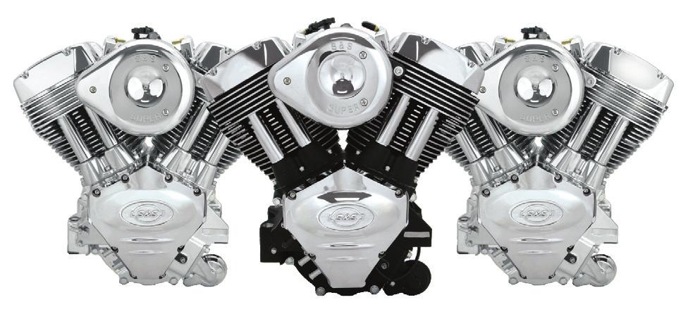

1 Owners Manual S&S X-Wedge Engines
2 DISCLAIMER: S&S parts are designed for high performance, closed course, racing applications and are intended for the very experienced rider only. The installation of S&S parts may void or adversely effect your factory warranty. In addition such installation and use may violate certain federal, state, and local laws, rules and ordinances as well as other laws when used on motor vehicles used on public highways, especially in states where pollution laws may apply. Always check federal, state, and local laws before modifying your motorcycle. It is the sole and exclusive responsibility of the user to determine the suitability of the product for his or her use, and the user shall assume all legal, personal injury risk and liability and all other obligations, duties, and risks associated therewith. The words Harley, Harley-Davidson, H-D, Sportster, Evolution, and all H-D part numbers and model designations are used in reference only. S&S Cycle is not associated with Harley-Davidson, Inc. SAFE INSTALLATION AND OPERATION RULES: Before installing your new S&S part it is your responsibility to read and follow the installation and maintenance procedures in these instructions and follow the basic rules below for your personal safety. Gasoline is extremely flammable and explosive under certain conditions and toxic when breathed. Do not smoke. Perform installation in a well ventilated area away from open flames or sparks. If motorcycle has been running, wait until engine and exhaust pipes have cooled down to avoid getting burned before performing any installation steps. Before performing any installation steps disconnect battery to eliminate potential sparks and inadvertent engagement of starter while working on electrical components. Read instructions thoroughly and carefully so all procedures are completely understood before performing any installation steps. Contact S&S with any questions you may have if any steps are unclear or any abnormalities occur during installation or operation of motorcycle with a S&S part on it. Consult an appropriate service manual for your motorcycle for correct disassembly and reassembly procedures for any parts that need to be removed to facilitate installation. Use good judgment when performing installation and operating motorcycle. Good judgment begins with a clear head. Don t let alcohol, drugs or fatigue impair your judgment. Start installation when you are fresh. Be sure all federal, state and local laws are obeyed with the installation. For optimum performance and safety and to minimize potential damage to carb or other components, use all mounting hardware that is provided and follow all installation instructions. Motorcycle exhaust fumes are toxic and poisonous and must not be breathed. Run motorcycle in a well ventilated area where fumes can dissipate. WARRANTY: All S&S parts are guaranteed to the original purchaser to be free of manufacturing defects in materials and workmanship for a period of twelve (12) months from the date of purchase. Merchandise that fails to conform to these conditions will be repaired or replaced at S&S s option if the parts are returned to us by the purchaser within the 12 month warranty period or within 10 days thereafter. In the event warranty service is required, the original purchaser must call or write S&S immediately with the problem. Some problems can be rectified by a telephone call and need no further course of action. A part that is suspect of being defective must not be replaced by a Dealer without prior authorization from S&S. If it is deemed necessary for S&S to make an evaluation to determine whether the part was defective, a return authorization number must be obtained from S&S. The parts must be packaged properly so as to not cause further damage and be returned prepaid to S&S with a copy of the original invoice of purchase and a detailed letter outlining the nature of the problem, how the part was used and the circumstances at the time of failure. If after an evaluation has been made by S&S and the part was found to be defective, repair, replacement, or refund will be granted.
3 ADDITIONAL WARRANTY PROVISIONS: (1) S&S shall have no obligation in the event an S&S part is modified by any other person or organization. (2) S&S shall have no obligation if an S&S part becomes defective in whole or in part as a result of improper installation, improper maintenance, improper use, abnormal operation, or any other misuse or mistreatment of the S&S part. (3) S&S shall not be liable for any consequential or incidental damages resulting from the failure of an S&S part, the breach of any warranties, the failure to deliver, delay in delivery, delivery in non-conforming condition, or for any other breach of contract or duty between S&S and a customer. (4) S&S parts are designed exclusively for use in Harley-Davidson and other American v-twin motorcycles. S&S shall have no warranty or liability obligation if an S&S part is used in any other application. Table of Contents: Introduction... 2 Engine Installation... 2 Oil Recommendations... 2 Oil Line Hook up... 2 Fuel Requirements... 4 General Break-in Procedure... 4 Tune Up Information... 6 Starting instructions... 6 Engine Service Intervals... 7 Engine Specifications... 9 Engine Dimensions Torque Specifications...14 Specifications and Wear Limits...16
4 INTRODUCTION The S&S engine you have purchased is an air-cooled, v-twin. It is designed to offer Proven Performance and reliability. Specifications for the X114, X117 and X121 engines, as well as specifications for big bore upgrade options, are found in this manual. They are based on current S&S production designs. Some changes may have been made over time as these engines have been in production for a number of years. Older engines may be somewhat different from the current specifications. ENGINE INSTALLATION Due the unique engine mounting locations a frame designed for the X-Wedge engine must be used. The engine must be mounted using the four mounting points on the lower cases and with a top support between the cylinder heads that is tied into the frame. The top support brace must connect the 3/8-16 tapped bolt holes located on top of each cylinder head above the intake port and 7/16 grade 8 bolts must be used in the lower mounts. The engine will accept the primary and charging system stator for a Harley-Davidson big twin engine, or equivalent. Follow the manufactures instructions for installing the primary and stator to the engine. OIL RECOMMENDATIONS S&S recommends synthetic engine oil such as S&S Premium Synthetic 20W50. However a premium petroleum based engine oil such as S&S Heavy Duty 20W50 is acceptable. Regardless of what type of oil you select, be sure to use only oil specifically designated for use in an air-cooled motorcycle, and select the viscosity suggested for the temperature range you will be operating your motorcycle in. VISCOSITY SAE 20W50 Above 35 SAE 10W40 Below 40 AMBIENT TEMPERATURE ( F) The S&S X-Wedge engine requires a spin-on filter with an anti-drain back valve, rated at 10 microns. The S&S oil filter part numbers are for Chrome and for Black. Filters for 1999-later Harley- Davidson big twins (# A and A) are also acceptable. OIL LINE HOOK-UP Clean the oil tank to remove any debris. Using new ½ ID hoses connect the oil return hose, oil supply hose, and the oil tank vent hose following the OIL LINE AND BREATHER SYSTEM DIAGRAM on the next page. 2 3
5 FUEL REQUIREMENTS The gasoline used in your engine should have a US octane rating of 91 or higher.. The United States uses the method of octane rating. In many countries outside the United States, the RON (Research Octane Number) is used, which will result in a higher octane requirement of about 96. BREAK-IN OIL CONSIDERATIONS. Either petroleum or synthetic oil designed for air-cooled v-twin engines can be used during the break-in period and during normal use. If preferred, petroleum oil can be used for the break-in period, after which, the engine can be changed over to synthetic oil. BREAK-IN PROCEDURE 1. Initial start up. Run engine approximately one minute at RPM. DO NOT crack throttle or subject to any loads during this period as head gaskets are susceptible to failure at this time. During this time, check to see that oil pressure is normal, that oil is returning the oil tank, and that no leaks exist. 2. Shut off engine and thoroughly check for any leaks or other problems. Let engine cool to the touch. 3. After engine has cooled, start up again and allow the motor to build some heat. Engine should be run no longer than three to four minutes. When the cylinders become warm/hot to the touch (approximately 150 F) shut the motor down and let it cool to room temp. Follow the same cautions as for the initial start-up, and continue to check for problems First 50 Miles: a. Street: Ride normally, do not lug the engine. Avoid high heat conditions and vary the RPM while riding. No stop and go traffic, extended idle periods, or high load or high RPM conditions. Max of 3,500 RPM or 60 MPH. b. Dyno: A chassis dynamometer can be used to put the first 50 miles on a new engine. See the notes and procedure below for chassis dyno break-in Miles: Ride normally, do not lug the engine. Avoid high heat conditions, no stop and go traffic or extended idle periods. Limited short bursts of throttle can aid in ring seating from this point forward during the break-in, but avoid continuous high speed or load conditions. Max of 4,250 RPM/70 MPH Miles: Avoid lugging the engine and high heat conditions. Max of 5,000 RPM. Change oil at 500 miles ,000 miles: Ride bike normally, but avoid continuous high load operation and high heat conditions. 8. From 1,000 miles on: Break-in is complete, enjoy! NOTES FOR COMPLETING INITIAL 50 MILE BREAK-IN AND INITIAL TUNING ON A CHASSIS DYNO When running the bike on the dyno it is critical that engine temperatures are monitored, AFR is kept between and the engine is not overheated. Fans must be used to keep the engine cool. When tuning under higher loads stop regularly and allow the engine to cool. A load must be placed on the engine to properly seat the rings. Running a new engine continually with no load will result in cylinder glazing and poor ring seal. The engine should be loaded to simulate close to the weight of the bike, a load of 10 15% on a Dyno jet 250i is usually sufficient. It is not recommended to use an inertia only dyno to break-in an engine as no load can be placed on the engine. Initial tuning on the engine can be completed during the initial 50 miles of dyno break-in. It is recommended the engine be run on the street for a minimum of 500 miles prior to completing tuning at full power. Monitor engine temperature during tuning to ensure the engine is not overheated. DYNO BREAK-IN PROCEDURE (FIRST 50 MILES) 1. Follow the same procedure outlined above for initial start-up and heat cycling the engine. 2. Run the bike for 25 miles on the dyno under varying speeds and loads while going up and down through the gears. Keep engine RPM below 3,500 RPM but do not lug the engine. The dyno must be operated so the engine runs under a load roughly equal to the power needed to move the bike down the road, this would be about 12 hp at 55 MPH. Keep engine head temperatures below 200 F at the temp sensor or surface of the head. Stop and cool the engine if needed. 3. Allow the engine to cool down to room temperature. 4. Run the bike for 25 more miles (50 miles total) under varying speeds, loads, and gears as before. Make sure there is some load on the engine. Keep engine speed below 4,250 RPM but do not lug the engine. Limited short bursts of throttle can aid in ring seating as long as the calibration/tune keeps the AFR in control. Keep engine head temperatures below 225 F at the temp sensor or surface of the head. 5. After the first 50 miles on the dyno, it is recommended the normal break-in schedule be followed under normal riding conditions on the street. See Step 5 under BREAK-IN PROCEDURE. GENERAL BREAK-IN NOTES Remember that these are air-cooled engines. Sufficient air movement is required to keep engine temperatures within safe operating limits. Avoid heavy traffic and congestion or extended idle periods whenever possible. S&S v-twin performance engines are designed for, and happiest when running between at normal highway speeds. Today s heavier bikes and taller gearing can easily push a high performance engine into a lugging condition which increases loads on engine components, causes detonation, builds excessive heat, and increases fuel consumption. If the engine does not accelerate easily when given some throttle, downshift to a lower gear. S&S engines benefit from a warm-up period any time they are started, allow engine to reach operating temperature before being subjected to heavy loads or quick throttle revs. 5

6 TUNE UP INFORMATION All S&S X-Wedge engines come from the factory with Champion RA8HC 12mm long reach spark plugs (S&S PN ). All spark plugs should be gapped between.038- and.042-inch. If you are not using an S&S ignition system, refer to your ignition manufacturer for any additional recommendations. IGNITION SYSTEM All S&S X-Wedge engines are fuel injected and are equipped with an S&S Variable Fuel Injection (VFI) module, which controls Ignition timing. The calibration file supplied by S&S for the particular engine contains ignition timing curves. If the ignition curves are modified or if another fuel injection module is used, the engine warranty may be voided. Emissions compliant engines must be run with the installed engine management system in order to maintain emissions compliance. If you choose to install another engine management system, make sure the rev limit is set no higher than 5800 rpm.. START-UP ENGINES EQUIPPED THE VARIABLE FUEL INJECTION (VFI) 1. Turn the ignition and kill switches on. Listen for the fuel pump as it pressurizes. 2. Do not twist the throttle open to prime the system. 3. Press the starter button and let engine crank over do not twist the throttle. If the engine is extremely hard to start hot or cold contact the S&S Tech Line or visit for the location of the closest VFI Tuning Center. 6 Nothing lasts forever, and despite the superior materials and design of the components in your S&S engine, some day it will need to be serviced. Who better to repair your engine, than the technicians at the company where it was made? To obtain factory service for your S&S engine, have your S&S dealer contact the S&S Service & Speed Center. To find an S&S dealer in your area go to the S&S Dealer Locator at CHARGING SYSTEM NOTE - If you are going to use a 45 amp alternator you must install a S&S spacer (PN ). If you do not use this spacer the rotor could bottom out against the case when the sprocket shaft nut is tightened. ITEM Engine oil & filter Air cleaner Petcock, lines & fittings vacuum lines Fuel tank filter screen & in-line fuel filter (if used) Engine idle speed Operation of throttle & enrichment device control Spark plugs Engine mounts External fasteners except engine head bolts Timing belt S&S RECOMMENDED REGULAR SERVICE INTERVALS INTERVAL Change at 500 and 2,500 miles. Every 2,500 miles thereafter or every six months, whichever comes first. 1 Inspect at 50 and 500 miles, every 2,500 miles thereafter. Replace every 5,000 miles. 1 Inspect at 50 and 500 miles, every 2,500 miles thereafter. Every 5,000 miles ,050 RPM. Non-adjustable. Inspect and lubricate throttle cables at 500 miles and every 2,500 miles thereafter. Inspect every 5,000 miles. Replace every 10,000 miles or as needed. Inspect at 500 miles and every 5,000 miles thereafter. Re-torque at 500 miles and every 5,000 thereafter. 1 Service more frequently if engine is operated in a dusty environment. Inspect for cracking every 5,000 miles. Replace every 20,000 miles. Belt should be checked for heat cracks more frequently if engine is operated in extreme heat or is idled for extended periods. 7
7 IMPORTANT INFORMATION S&S engines are not recommended for inexperienced riders because the increased performance requires a higher level of riding skill. Do not lug your S&S engine. This is a high performance engine, designed to produce excellent horsepower at higher RPM. It is not well suited to pull heavy loads at low RPM. We recommend that the engine not be operated below 2500 RPM for extended periods of time. Shift to a lower gear to keep the engine speed up when traveling at lower speeds. Your S&S Engine is air cooled, which means that it depends on air moving across the cooling fins to keep it from over heating. Do not allow your engine to idle for extended periods of time. Avoid stop and go traffic or any other situation where the motorcycle is not moving while the engine is running. To avoid engine damage, do not operate the engine above 5800 RPM. ENGINE SPECIFICATIONS The following charts contain information and engine specifications of the complete S&S X-Wedge engines covered by this owners manual, as well as available big bore upgrades, including camshaft recommendations. Cylinder V angle Cam drive Valve train Pistons Crankshaft Rod type Bearing type Oil system Induction and Engine Management Complete engine weight ENGINE CONFIGURATION degrees 30 mm wide belt with automatic tensioner Hydraulic roller tappet with pushrods Forged, common front and rear Forged and nitrided one piece forged, split design 7/16 bolt Tri metal plain style rod and main Dry sump, internal gerotor pump 2 1/16 throttle body with S&S closed loop VFI 163 lbs 8 9
8 ENGINE SPECIFICATIONS (CONTINUTED) Stock X-Wedge Engine Configurations Engine Bore Stroke Cylinder Length Compression Ratio Cam Set Engine Management X /8 4 1/ " 8.6:1 548 S&S VFI X /8 4 3/ " 9.75:1 545E S&S VFI X /4 4 1/ " 9.75:1 545E S&S VFI Big Bore Upgrades Bore Stroke Cylinder Length Compression Ratio Recommended Cam Set Engine Management X /8 4 1/ " 9.7:1 569E S&S VFI X /8 4 3/ " 10.3:1 569E S&S VFI ENGINE DIMENSIONS The X-Wedge engine was primarily designed for custom built motorcycles with special frames. X-Wedge engines do not fit in stock Harley- Davidson chassis. The following diagrams show the detailed dimensions that will be needed in order to build a custom frame. All S&S X-Wedge engines, regardless of displacement, have the same exterior dimensions
9 CENTER OF GRAVITY 12 13
10 SERVICE SPECIFICATIONS FOR S&S ENGINES For the most part if an S&S engine requires service, a qualified mechanic who services air cooled motorcycle engines can do the work. However the specifications for S&S engines are unique. These charts are provided for reference. For more detailed information about any specific S&S component, installation instructions are available for free download from the S&S website TORQUE SPECIFICATIONS Item Torque Recommended Rocker Box ft-lbs 243 blue Cylinder head bolts Cylinder studs in case 8ft-lbs, 18 ft-lbs, then 90 Oil 10 ft-lbs 272 red Crankcase fasteners ft-lbs 243 blue TORQUE SPECIFICATIONS (CONTINUED) Item Torque Recommended Spark plug ft-lbs Antiseize Backplate to throttle body ft-lbs 243 Oil filter mount ft-lbs 243 Oil filter to mount ½ to 3/4 turn after gasket contact None Item Torque Recommended Air temp sensor 6-8 in-lbs 222 Back plate to head bolts MAP sensor (hold down) ft-lbs in-lbs 222 Air cleaner cover in-lbs 243 Rocker arm nuts 30 ft-lbs 272 red Tappet cover fasteners Cam chest cover fasteners Intake manifold to head Intake manifold to throttle body Exhaust flange to head ft-lbs in-lbs ft-lbs in-lbs 222 purple ft-lbs Antiseize Head temp sensor ft-lbs Antiseize Knock sensor ft-lbs 243 blue Crank position sensor in-lbs 243 Cam nut 60 ft-lbs 243 Pinion bolt 35 ft-lbs Oil Oil pump mounting bolts Oil pump assembly bolts Front engine mount bolts ft-lbs in-lbs ft-lbs 243 Rear engine bolts ft-lbs 243 Top engine mount to head Inner primary to engine ft-lbs ft-lbs 243 Idle control motor in-lbs 222 Reed valve screws in-lbs 222 purple Rod bolt 23 ft-lbs, 45 Oil Belt cover in-lbs 243 Idler sprockets ft-lbs 243 Belt tensioner 40 ft-lbs 272 Fuel injector (hold down) All other 1/4-20 fasteners All other 5/16 fasteners in-lbs in-lbs ft-lbs
11 CYLINDER HEADS VALVES (fit in guide) CLEARANCE SPECIFICATIONS AND SERVICE WEAR LIMITS DESCRIPTION SPECIFICATION WEAR LIMIT Valve guide in head (tight) Valve seat in head (tight) ( mm) ( mm) Intake ( mm) ( mm) Intake seat width (0.787 mm) (0.104 mm) Exhaust ( mm) ( mm) Exhaust seat width (1.193 mm) (0.145 mm) Seat width ( mm) N/A Stem protrusion 2.190, , (55.626, , mm) ( mm) HYDRAULIC LIFTERS Lifter fit to guide (loose) ( mm) (0.076 mm) PISTONS CONNECTING RODS 16 FLYWHEELS Fit in cylinder (41/8 bore) ( mm) (0.127 mm) End gap: top compression ring ( mm) (0.660 mm) End gap: 2nd compression ring ( mm (0.863 mm) Oil control rails ( mm) (1.27 mm) Crankpin bearing running clearance ( mm) (0.051 mm) Piston pin fitment in rod ( mm) (0.051 mm) Connecting rod side play ( mm) (1.016 mm) Runout (shaft at flywheel) ( mm) (0.076 mm) End play ( mm) Exceeds (0.381 mm) CAM CHEST Camshaft endplay (non-adjustable) ( mm) N/A
12 OWNERS MANUAL NOTES
13 S&S Cycle, Inc County Hwy G Viola, WI Phone: Fax: Technical Service Phone: TECH (8324) Technical Service sstech@sscycle.com /24/16 Copyright 2016 by S&S Cycle, Inc. All rights reserved. Printed in the U.S.A.
S&S. Cycle, Inc. Installation Instructions: Cam Support Plate for 2017-up M8 Models. Instruction
 Instruction 0-0 0-0- Version 0 by S&S Cycle, Inc. All rights reserved. Printed in the U.S.A. S&S Cycle, Inc. 0 Cty Hwy G Viola, Wisconsin Phone: 0-- Fax: 0-- Technical Service Phone: 0--TECH () Technical
S&S. Installation Instructions: Pistons for Harley-Davidson CVO 110 Engines. Instruction Copyright 2015 by S&S Cycle, Inc.
 Instruction 510-0369 02-27-15 Copyright 2015 by S&S Cycle, Inc. All rights reserved. Printed in the U.S.A. S&S Cycle, Inc. 14025 Cty Hwy G PO Box 215 Viola, Wisconsin 54664 Phone: 608-627-1497 Fax: 608-627-1488
S&S. Installation Instructions for S&S Single Bore Tuned Induction Kit for 2008-Up Touring Models with Electronic Throttle Control
 Instruction 106-4891 06-24-14 Copyright 2009, 2014 by S&S Cycle, Inc. All rights reserved. Printed in the U.S.A. S&S Cycle, Inc. 14025 County Highway G PO Box 215 Viola, Wisconsin 54664 Phone: 608-627-1497
S&S. S&S Oil Supply Line Installation Kit PN (For Harley-Davidson Dyna Models) PN (For FLT Models)
 PN (For FLT Models)") Instruction 510-0039 03-07-13 Copyright 2011, 2013 by S&S Cycle, Inc. All rights reserved. Printed in the U.S.A. S&S Cycle, Inc. 14025 County Highway G PO Box 215 Viola, Wisconsin 54664 Phone: 608-627-1497
Instruction 510-0039 03-07-13 Copyright 2011, 2013 by S&S Cycle, Inc. All rights reserved. Printed in the U.S.A. S&S Cycle, Inc. 14025 County Highway G PO Box 215 Viola, Wisconsin 54664 Phone: 608-627-1497
S&S. Installation Instructions: S&S Stealth Air Cleaner Covers. Instruction IMPORTANT NOTICE:
 Instruction 510-0226 09-03-13 Copyright 2013 by S&S Cycle, Inc. All rights reserved. Printed in the U.S.A. S&S Cycle, Inc. 14025 Cty Hwy G PO Box 215 Viola, Wisconsin 54664 Phone: 608-627-1497 Fax: 608-627-1488
S&S. Installation Instructions for S&S VFI Knock Sensor Kit for 2001-'07 Delphi Style VFI Module (with USB) Instruction
 Instruction") Instruction 106-1544 9-28-07 Copyright 2007 by S&S Cycle, Inc. All rights reserved. Printed in the U.S.A. S&S Cycle, Inc. 235 Causeway Blvd. La Crosse, Wisconsin 54603 Phone: 608-627-1497 Fax: 608-627-1488
Instruction 106-1544 9-28-07 Copyright 2007 by S&S Cycle, Inc. All rights reserved. Printed in the U.S.A. S&S Cycle, Inc. 235 Causeway Blvd. La Crosse, Wisconsin 54603 Phone: 608-627-1497 Fax: 608-627-1488
S&S. Instruction Copyright 2014, Version 4 by S&S Cycle, Inc.
 Instruction 510-0295 10-02-2017 Copyright 2014, 2016. 2017 Version 4 by S&S Cycle, Inc. All rights reserved. Printed in the U.S.A. S&S Cycle, Inc. 14025 Cty Hwy G PO Box 215 Viola, Wisconsin 54664 Phone:
Owners Manual. S&S V-Series Engines
 Owners Manual S&S V-Series Engines DISCLAIMER: S&S parts are designed for high performance, closed course, racing applications and are intended for the very experienced rider only. The installation of
Cycle, Inc. S&S. Installation Instructions: Chain Drive Camshaft for 2017 Harley-Davidson Milwaukee Eight Engines. Instruction
 Instruction 0-067 0-8-07 Version Copyright 07 by S&S Cycle, Inc. All rights reserved. Printed in the U.S.A. S&S Cycle, Inc. 0 Cty Hwy G Viola, Wisconsin 66 Phone: 608-67-97 Fax: 608-67-88 Technical Service
S&S. Installation Instructions: S&S Billet Air Cleaner Kit PN for Victory Motorcycles. Instruction IMPORTANT NOTICE:
 Instruction 106-1330 06-23-10 Copyright 2008, 2009, & 2010 by S&S Cycle, Inc. All rights reserved. Printed in the U.S.A. S&S Cycle, Inc. 14025 Cty Hwy G PO Box 215 Viola, Wisconsin 54664 Phone: 608-627-1497
S&S. Installation Instructions for S&S Sealed Air Cleaner. Instruction IMPORTANT NOTICE:
 Instruction 106-2707 11-20-08 Copyright 2008 by S&S Cycle, Inc. All rights reserved. Printed in the U.S.A. S&S Cycle, Inc. 235 Causeway Blvd. La Crosse, Wisconsin 54603 Phone: 608-627-1497 Fax: 608-627-1488
Installation Instructions for S&S Single Bore Throttle Bodies
 Instruction 1-1270 12-29-1 Rev 2 Copyright 2009, 201 by S&S Cycle, Inc. All rights reserved. Printed in the U.S.A. S&S Cycle, Inc. 1402 Cty Hwy G PO Box 21 Viola, Wisconsin 4664 Phone: 608-627-1497 Fax:
S&S. Instruction IMPORTANT NOTICE:
 Instruction 106-4426 10-31-08 Copyright 2008 by S&S Cycle, Inc. All rights reserved. Printed in the U.S.A. S&S Cycle, Inc. 235 Causeway Blvd. La Crosse, Wisconsin 54603 Phone: 608-627-1497 Fax: 608-627-1488
Cycle, Inc Cty Hwy G Viola, Wisconsin Phone: Fax:
 Instruction 510-0414 11-14-16 Version 3 Copyright 016 by S&S Cycle, Inc. All rights reserved. Printed in the U.S.A. S&S Cycle, Inc. 1405 Cty Hwy G Viola, Wisconsin 54664 Phone: 608-67-1497 Fax: 608-67-1488
Installation Instructions for S&S Single Bore Throttle Bodies
 Instruction 51-1239 12-29-15 Rev 2 Copyright 2009, 2015 by S&S Cycle, Inc. All rights reserved. Printed in the U.S.A. S&S Cycle, Inc. 14025 Cty Hwy G PO Box 215 Viola, Wisconsin 54664 Phone: 608-627-1497
Cycle, Inc Cty Hwy G Viola, Wisconsin Phone: Fax:
 Instruction 510-0481 09-10-18 Version 1 2018 by S&S Cycle, Inc. All rights reserved. Printed in the U.S.A. S&S Cycle, Inc. 14025 Cty Hwy G Viola, Wisconsin 54664 Phone: 608-627-1497 Fax: 608-627-1488 Technical
Lloydz Indian Air Filter w/custom Cover
 IMC-215/220-I 8.28.2015 Lloydz Motor Workz 25 railroad Ave PO Box 11 Pine Bush, NY 12566 Lloydz Indian Air Filter w/custom Cover VICTORY/INDIAN WARRANTY POLICY: Lloydz Indian Air Filter is intended for
Cycle, Inc. 235 Causeway Blvd. La Crosse, Wisconsin 54603
 Instruction 51-1196 4-7-06 Copyright 2001, 2004, 2006 by S&S Cycle, Inc. All rights reserved. Printed in the U.S.A. S&S Cycle, Inc. 235 Causeway Blvd. La Crosse, Wisconsin 54603 Phone: 608-627-1497 Fax:
S&S Cycle, Inc County Hwy. G Box 215 Viola, Wisconsin U.S.A.
 Instruction Sheet 51-1046 1-28-03 Copyright 1999, 2003 by S&S Cycle, Inc. All rights reserved. Printed in the U.S.A. S&S Cycle, Inc. 14025 County Hwy. G Box 215 Viola, Wisconsin 54664 U.S.A. Phone 608-627-2080
From The Track... To The Street!
 Instruction Sheet For JIMS Twin Cam Flywheel Assemblies & Big Bore Kit For the following part numbers 1881, 1882, 1883, 1884, 1886, 1888, 1937, 1938, 1941, 1942, 1943, 1944, 1945, 1946, 1957, 1958, 1959,
s&s e e, 1~. 235 Causeway Blvd. La Crosse, Wisconsin 54603
 Instruction 51-121 6 5-4-06 Copyright o 2005, 2006 by S&S Cycle, Inc. All rights reserved. Printed in the U.S.A. s&s e e, 1~. 235 Causeway Blvd. La Crosse, Wisconsin 54603 Phone: 608-627-1497 Fax: 608-627-1488
Cycle, Inc. 235 Causeway Blvd. La Crosse, Wisconsin 54603
 Instruction 51-1047 4-8-06 Copyright 2003, 2004, 2006 by S&S Cycle, Inc. All rights reserved. Printed in the U.S.A. S&S Cycle, Inc. 235 Causeway Blvd. La Crosse, Wisconsin 54603 Phone: 608-627-1497 Fax:
Quality Work with Quailty People
 Manuafactured by : DRM Industries Corp. Quality Work with Quailty People 231 W. Adams St. PO Box 758 Lake Delton, WI 53959 Call for Customer Sevice at 608-254-8158 7am to 4pm Monday - Friday Email: framelock@drmindustries.com
S&S. S&S V-Series California Engine Owner's Manual. Instruction IMPORTANT NOTICE:
 Instruction 510-0231 12-4-13 Copyright 2014 by S&S Cycle, Inc. All rights reserved. Printed in the U.S.A. S&S Cycle, Inc. 235 Causeway Blvd. La Crosse, Wisconsin 54603 Phone: 608-627-1497 Fax: 608-627-1488
S&S. Installation Instructions: S&S Standard and Easy Start Gear Drive Cams for Harley-Davidson Twin Cam 88 Engines. Instruction
 Instruction 106-5893 11-18-09 Copyright 2009 by S&S Cycle, Inc. All rights reserved. Printed in the U.S.A. S&S Cycle, Inc. 14025 Cty Hwy G PO Box 215 Viola, Wisconsin 54664 Phone: 608-627-1497 Fax: 608-627-1488
S&S. Instruction IMPORTANT NOTICE:
 Instruction 106-6415 09-19-12 Copyright 2009, 2011, 2012 by S&S Cycle, Inc. All rights reserved. Printed in the U.S.A. S&S Cycle, Inc. 14025 Cty Hwy G PO Box 215 Viola, Wisconsin 54664 Phone: 608-627-1497
SE120R SCREAMIN' EAGLE PRO RACE-USE CRATE ENGINE
 -J007 REV. 00-09-08 SE0R SCREAMIN' EAGLE PRO RACE-USE CRATE ENGINE GENERAL Kit Number 90- Models For model fitment information, see the P&A Retail Catalog or the Parts and Accessories section of www.harley-davidson.com
ASSEMBLY DIAGRAM AND ASSEMBLY REFERENCE ULTIMA OLD SCHOOL 2 BELT DRIVE UNITS
 ASSEMBLY DIAGRAM AND ASSEMBLY REFERENCE ULTIMA OLD SCHOOL 2 BELT DRIVE UNITS BELT DRIVE ASSEMBLIES Part# 58-850 2 Old School Belt Drive Assembly - Polished Part# 58-851 2 Old School Belt Drive Assembly
DYNA EVO & T.C. MODELS 91-05
 ASSEMBLY DIAGRAM AND ASSEMBLY REFERENCE ULTIMA OLD SCHOOL 2 BELT DRIVE UNITS DYNA EVO & T.C. MODELS 91-05 Part # 58-900 2 BELT DRIVE ASSEMBLY REV 1-20-10 ASSEMBLY DIAGRAM AND ASSEMBLY REFERENCE ULTIMA
DYNA EVO & T.C. MODELS 91-05
 ASSEMBLY DIAGRAM AND ASSEMBLY REFERENCE ULTIMA OLD SCHOOL 2 BELT DRIVE UNITS DYNA EVO & T.C. MODELS 91-05 Part # 58-900 2 BELT DRIVE ASSEMBLY REV 10-22-14 ASSEMBLY DIAGRAM AND ASSEMBLY REFERENCE ULTIMA
S&S. Installation Instructions: S&S IST Ignition System for /8" Bore Big Twin Engines. Instruction IMPORTANT NOTICE:
 Instruction 51-1155 04-21-15 Copyright 2009, 2010, & 2012 by S&S Cycle, Inc. All rights reserved. Printed in the U.S.A. S&S Cycle, Inc. 14025 County Highway G Viola, WI 54664 Phone: 608-627-1497 Fax: 608-627-1488
S&S. Installation Instructions: S&S Complete Gear Drive Cam Chest Kit For Harley-Davidson Big Twins
 Instruction 10-00 0-1-01 Copyright 01 Version 1 by S&S Cycle, Inc. All rights reserved. Printed in the U.S.A. S&S Cycle, Inc. 10 Cty Hwy G PO Box 1 Viola, Wisconsin Phone: 0--19 Fax: 0--1 Technical Service
BAKER CRUISE DRIVE TOP COVER BAKER 1.5 OIL PAN
 BAKER BAKER CRUISE 1.5 DRIVE OIL TOP PAN COVER PN: BD-1.5B Wrinkle Black Highlighted Pan Assembly BD-1.5CVO Granite Highlighted Pan Assembly CVO Models BD-1.5P Show Polished Pan Assembly BD-1.5C Chrome
Cycle, Inc. 235 Causeway Blvd. La Crosse, Wisconsin 54603
 Instruction 51-1160 10-26-06 Copyright, 2003, 2006 by S&S Cycle, Inc. All rights reserved. Printed in the U.S.A. S&S Cycle, Inc. 235 Causeway Blvd. La Crosse, Wisconsin 54603 Phone: 60-627-1497 Fax: 60-627-14
Cycle, Inc Cty Hwy G PO Box 215 Viola, Wisconsin 54664
 Instruction 51-1116 10-19-11 Copyright 2008, 2011 by S&S Cycle, Inc. All rights reserved. Printed in the U.S.A. S&S Cycle, Inc. 14025 Cty Hwy G PO Box 215 Viola, Wisconsin 54664 Phone: 608-627-1497 Fax:
BAKER ATTITUDE CHAIN ADJUSTER
 PN 177-67K INSTALLATION INSTRUCTIONS FEATURES TAG PN QTY DESCRIPTION 1 13061 2 5/16-18 X 2, Hex Bolt, Zinc 2 6100 2 5/16 ID AN Washers, SS 3 25CNTE8Y 1 1/4-20 Low Head Nylock Nut 4 178-67 1 Support Plate,
carbureted evo press flywheel kits
 carbureted evo press flywheel kits Use on 1970-1984 Shovelhead or 1984 1999 Evolution These instruction are for the following part numbers: 1972,1973,1974,1976,1977,1978, 1979,1980,1981,1982,1983,1984,1985,1986,1987.
S&S. Installation Instructions: S&S Complete Gear Drive Cam Chest Kit For Harley-Davidson Big Twins
 Instruction 510-0402 05-10-2016 Copyright 2016 Version 1 by S&S Cycle, Inc. All rights reserved. Printed in the U.S.A. S&S Cycle, Inc. 14025 Cty Hwy G PO Box 215 Viola, Wisconsin 54664 Phone: 60-62-14
INSTALLATION HYPERCHARGER AIR FILTER KIT 9754
 9754 PARTS INCLUDED 1 Chrome Hypercharger Assembly 1 Support Bracket 1 Breather Hardware Kit, including: 2 1-1/4 Breather Bolts 2 Breather Hoses 4 Shim Washers 1 Twin Cam Breather Kit, Including: 1 Breather
INSTALLATION HYPERCHARGER AIR FILTER KIT 9992
 9992 PARTS INCLUDED 1 Chrome Hypercharger Assembly with Chrome Blood Groove Trap Door and Chrome Butterflies 1 Support Bracket 1 Breather Hardware Kit, including: 2 1-1/4 Breather Bolts 2 Breather Hoses
introduction Welcome to Midwest Motorcycle Supply s Engine Reference Guide.
 introduction Welcome to Midwest Motorcycle Supply s Engine Reference Guide. In an effort to make servicing your V-Twin engine easier, the staff at Midwest Motorcycle Supply have put together what we believe
INSTALLATION INSTRUCTIONS
 INSTALLATION INSTRUCTIONS v.102306 BAKER COMPENSATING SPROCKET for 1985-2006 h-d FLT & FXR P/N 155-56S P/N 156-56S P/N 157-56S for 1985-2006 H-D SOFTAIL & DYNA P/N 155-56L P/N 156-56L P/N 157-56L BAKER
HSR Carburetor. Total Kits. Installation Instructions. # Evo Big Twin # present Twin Cam
 HSR Carburetor Total Kits Installation Instructions HSR42 Kits: HSR45 Kits: #42-8 84-99 Evo Big Twin #42-19 99 - present Twin Cam #45-2 84-99 Evo Big Twin #45-3 84-99 Evo Big Twin #45-4 99 - present Twin
Cycle, Inc. 235 Causeway Blvd. La Crosse, Wisconsin 54603
 Instruction 51-1042 4-6-06 Copyright 1999, 2000, 2005, 2006 by S&S Cycle, Inc. All rights reserved. Printed in the U.S.A. S&S Cycle, Inc. 235 Causeway Blvd. La Crosse, Wisconsin 54603 Phone: 608-627-1497
HSR Carburetor. Total Kits. Installation Instructions. # Evo Big Twin # present Twin Cam
 HSR Carburetor Total Kits Installation Instructions HSR42 Kits: HSR45 Kits: #42-8 84-99 Evo Big Twin #42-19 99 - present Twin Cam #45-2 84-99 Evo Big Twin #45-3 84-99 Evo Big Twin #45-4 99 - present Twin
3. INSPECTION/ADJUSTMENT
 3 SERVICE INFORMATION...3-0 FINAL REDUCTION GEAR OIL...3-7 MAINTENANCE SCHEDULE...3-2 DRIVE BELT...3-7 FUEL FILTER...3-3 BRAKE SHOE...3-8 THROTTLE OPERATION...3-3 BRAKE ADJUSTING NUT...3-8 AIR CLEANER...3-4
Function Formed FL Oil Spout
 Installation Instructions Function Formed FL Oil Spout over view Function Formed FL Oil Spout v.102516 FEATURES: The new line of BAKER FL Oil Spouts follows on the heels of other BAKER Function Formed
INSTALLATION INSTRUCTIONS
 INSTALLATION INSTRUCTIONS RIOT DYNA MINIMUM REQUIRED TOOLS: FLAT HEAD SCREWDRIVER 1/2, 9/16, 14mm, 7/8 or 22mm WRENCHES 5/16, 1/2, 9/16 SOCKETS AND RATCHET SNAP RING PILERS 3/16, 1/4, 5/16 ALLEN WRENCH
S&S Cycle, Inc. General Flywheel Instructions
 Instruction sheet No. 2002 Revised 6-29-99 Copyright 1995 by S&S Cycle, Inc. All rights reserved. Printed in the U.S.A. SAFE INSTALLATION AND OPERATION RULES: Before installing your new S&S flywheels it
HSR Carburetor Easy Kits Installation Instructions For Evo Big Twin Kit: # 42-7 Twin Cam Kit: # 42-18
 HSR Carburetor Easy Kits Installation Instructions For Evo Big Twin Kit: # 42-7 Twin Cam Kit: # 42-18 Revised 5/01/01 EK-1 Easy Kit Installation Instructions The HSR series carburetors are precise yet
INSTALLATION INSTRUCTIONS
 INSTALLATION INSTRUCTIONS RIOT DYNA MINIMUM REQUIRED TOOLS: FLAT HEAD SCREWDRIVER 1/2, 9/16, 14mm, 7/8 or 22mm WRENCHES 5/16, 1/2, 9/16 SOCKETS AND RATCHET SNAP RING PILERS 3/16, 1/4, 5/16 ALLEN WRENCH
KING KONG CLUTCH INSTALLATION INSTRUCTIONS
 KING KONG CLUTCH INSTALLATION INSTRUCTIONS over view BAKER KING KONG CLUTCH V.05_091008 FEATURES: 1 Piece steel clutch basket design 66 tooth ring gear configuration, 23% thicker than stock 20 massive
Installation Instructions: Subaru CS600 & CS600X Long Block Block Assemblies
 Part Number: 20000160, 20000161, 20000162, 20002503, 20002504, 20002505, 20002506, 20003488, 20003489, 20003490, 20007211, 20007212, 20007213, 20007705, 20007706, 20007707, 20007708, 20007709, 20007710,
Installation Instructions
 Installation Instructions INSTALLATION INSTRUCTIONS over view V.031407 FEATURES BAKER FUNCTION FORMED PRIMARY ALL BILLET 6061-T6 AIRCRAFT GRADE ALUMINUM CONSTRUCTION One piece STARTER jackshaft (INCLUDED)
INSTALLATION INSTRUCTIONS
 INSTALLATION INSTRUCTIONS PRO DUALS TOURING MINIMUM REQUIRED TOOLS: FLAT HEAD SCREWDRIVER 1/2, 9/16, 14mm, 7/8 or 22mm WRENCHES 5/16, 1/2, 9/16 SOCKETS AND RATCHET SNAP RING PILERS 3/16, 1/4, 5/16 ALLEN
Racing Performance Catalog & Reference Guide Model/Type:
 Version 4/08 Racing Performance Catalog & Reference Guide Model/Type: 124435 8105-01 Table of Contents SAFETY... 1 WORLD FORMULA General Specs...3 Special Tools...3 Torque Specs...3 Racing Specifics...3
MOTORCYCLE / ATV 2010 Distributor s Warranty
 MOTORCYCLE / ATV 2010 Distributor s Warranty Reorder Part No.:00X38-M10-W000 RG.30000.2009.03.10 V.I.N. DATE OF SALE SELLING DEALER DISTRIBUTOR S WARRANTY Honda Canada Inc., for and on behalf of Honda
V PN 4-155N1-K (N1 Shift Drum Kit For Ratchet Style Top Covers) PAGE 1 COVER
 PAGE 1 COVER") BAKER 4-SPEED CRUISE N1 DRIVE SHIFT TOP DRUM COVER KIT V3-05222014 PN 4-155N1-K (N1 Shift Drum Kit For Ratchet Style Top Covers) PAGE 1 COVER FEATURES Tired of stalling your jockey shift bike while trying
BAKER 4-SPEED CRUISE N1 DRIVE SHIFT TOP DRUM COVER KIT V3-05222014 PN 4-155N1-K (N1 Shift Drum Kit For Ratchet Style Top Covers) PAGE 1 COVER FEATURES Tired of stalling your jockey shift bike while trying
POWER CELL FOR DYNA WITH CLEAN CHROME COVER 562
 POWER CELL FOR DYNA WITH CLEAN CHROME COVER 562 THANK YOU FOR CHOOSING CRUSHER! PROTECT YOURSELF AND OTHERS FROM POTENTIAL INJURY AND PROPERTY DAMAGE OR LOSS. PAY CLOSE ATTENTION TO ALL INSTRUCTIONS, WARNINGS,
Cycle, Inc Cty Hwy G, PO Box 215 Viola, Wisconsin Phone: Fax:
 Manual -00 0--0 Revison Copyright 0, 0 by S&S Cycle, Inc. All rights reserved. Printed in the U.S.A. S&S Cycle, Inc. 0 Cty Hwy G, PO Box Viola, Wisconsin Phone: 0-- Fax: 0-- Technical Service Phone: 0--TECH
CRUSHER MAVERICK 2 INTO 2, BLACK 566
 CRUSHER MAVERICK 2 INTO 2, BLACK 566 THANK YOU FOR CHOOSING CRUSHER! PROTECT YOURSELF AND OTHERS FROM POTENTIAL INJURY AND PROPERTY DAMAGE OR LOSS. PAY CLOSE ATTENTION TO ALL INSTRUCTIONS, WARNINGS, CAUTIONS,
Reproduction. Not for. Briggsracing.com. CORPORATION Briggs & Stratton Corporation MS /08
 Briggsracing.com MS-5702-4/08 BRIGGS&STRATTON CORPORATION Post office box 702 Milwaukee, WI 53201 USA 414 259 5333 2008 Briggs & Stratton Corporation Version 4/08 Racing Performance Catalog & Reference
SPECIFICATIONS TEST AND ADJUSTMENT SPECIFICATIONS SPECIFICATIONS ENGINE FD620D, K SERIES
 TEST AND ADJUSTMENT Engine Oil Pressure Sensor Activates............................... 98 kpa (14.2 psi) Oil Pressure While Cranking (Minimum).......................... 28 kpa (4 psi) Oil Pressure.....................................
S&S Billet Pro Stock Engine Assembly # (Complete), # (No Electrics), # (No Electrics)
, # (No Electrics), # (No Electrics)") Manual -00 --0 Copyright 0 by S&S Cycle, Inc. All rights reserved. Printed in the U.S.A. S&S Cycle, Inc. 0 Cty Hwy G, PO Box Viola, Wisconsin 66 Phone: 608-67-97 Fax: 608-67-88 Technical Service Phone:
Manual -00 --0 Copyright 0 by S&S Cycle, Inc. All rights reserved. Printed in the U.S.A. S&S Cycle, Inc. 0 Cty Hwy G, PO Box Viola, Wisconsin 66 Phone: 608-67-97 Fax: 608-67-88 Technical Service Phone:
MOTORCYCLE / ATV DISTRIBUTOR S WARRANTY
 MOTORCYCLE / ATV 2014> Distributor s Warranty DISTRIBUTOR S WARRANTY Honda Canada Inc., for and on behalf of Honda Motor Co. Ltd., Tokyo, Japan, gives the following written warranties on each new Honda
SPECIFICATIONS TEST AND ADJUSTMENT SPECIFICATIONS SPECIFICATIONS ENGINE FD620D, K SERIES
 ENGINE FD620D, K SERIES SPECIFICATIONS SPECIFICATIONS TEST AND ADJUSTMENT SPECIFICATIONS Engine Oil Pressure Sensor Activates............................... 98 kpa (14.2 psi) Oil Pressure While Cranking
baker+1 oil Pan installation
 Installation Instructions over view baker+1 oil Pan installation V.2-29-08 FEATURES: 2 piece Billet Aircraft Grade 6061-T6 Aluminum Reduces engine oil temperature by 10 degrees on an 80 degree day. Multiple
Performer RPM Camshaft/Lifters/Lube Kit CATALOG #7106 MODEL: c.i.d. Ford V8
 Performer RPM Camshaft/Lifters/Lube Kit MODEL: 352-428 c.i.d. Ford V8 PLEASE study these instructions carefully before installing your new camshaft. If you have any questions or problems, do not hesitate
630, 631 & 632 Bobcat & Melroe Bobcat
 Bobcat 630, 631 & 632 Bobcat & Melroe Bobcat THIS IS A MANUAL PRODUCED BY JENSALES INC. WITHOUT THE AUTHORIZATION OF BOBCAT OR IT S SUCCESSORS. BOBCAT AND IT S SUCCESSORS ARE NOT RESPONSIBLE FOR THE QUALITY
INSTALLATION INSTRUCTIONS
 INSTALLATION INSTRUCTIONS ROCKSTAR SOFTAIL MINIMUM REQUIRED TOOLS: FLAT HEAD SCREWDRIVER 1/2, 9/16, 14mm, 7/8 or 22mm WRENCHES 5/16, 1/2, 9/16 SOCKETS AND RATCHET SNAP RING PILERS 3/16, 1/4, 5/16 ALLEN
CRUSHER TRUE DUAL HEADPIPES 513
 CRUSHER TRUE DUAL HEADPIPES 513 THANK YOU FOR CHOOSING CRUSHER! PROTECT YOURSELF AND OTHERS FROM POTENTIAL INJURY AND PROPERTY DAMAGE OR LOSS. PAY CLOSE ATTENTION TO ALL INSTRUCTIONS, WARNINGS, CAUTIONS,
INSTALLATION INSTRUCTIONS
 PERFORMER 2 INTO 1 TOURING MINIMUM REQUIRED TOOLS: INSTALLATION INSTRUCTIONS FLAT HEAD SCREWDRIVER 1/2, 9/16, 14mm, 7/8 or 22mm WRENCHES 5/16, 1/2, 9/16 SOCKETS AND RATCHET SNAP RING PILERS 3/16, 1/4,
3. INSPECTION/ADJUSTMENT
 SERVICE INFORMATION...3-0 FINAL REDUCTION GEAR OIL...3-7 MAINTENANCE SCHEDULE...3-2 DRIVE BELT...3-7 FUEL FILTER...3-3 BRAKE SHOE...3-8 THROTTLE OPERATION...3-3 BRAKE ADJUSTING NUT...3-8 AIR CLEANER...3-4
INSTALLATION INSTRUCTIONS
 MINIMUM REQUIRED TOOLS: INSTALLATION INSTRUCTIONS LOWDOWN SOFTAIL FLAT HEAD SCREWDRIVER 1/2, 9/16, 14mm, 7/8 or 22mm WRENCHES 5/16, 1/2, 9/16 SOCKETS AND RATCHET SNAP RING PILERS 3/16, 1/4, 5/16 ALLEN
INSTALLATION INSTRUCTIONS
 MINIMUM REQUIRED TOOLS: INSTALLATION INSTRUCTIONS LOWDOWN SPORTSTER FLAT HEAD SCREWDRIVER 1/2, 9/16, 14mm, 7/8 or 22mm WRENCHES 5/16, 1/2, 9/16 SOCKETS AND RATCHET SNAP RING PILERS 3/16, 1/4, 5/16 ALLEN
Installation Instructions: Mitsubishi 4B11 Stroker Kit
 Part Number: 20007783 Applications: Mitsubishi 4B11 EVO X (2.2L) Disclaimer and Warranty A vehicle modified with Cosworth competition and or racing performance products will not meet the legal requirements
Kit Instruction Manual
 Kit Instruction Manual Thank you for purchasing one of our products. Please strictly follow the instruction to install and use the products. Before fitting the products, please be sure to check the contents
Roller Camshaft Installation
 Installation Instructions Roller Camshaft Installation For more information, see www.cranecams.com READ CAREFULLY AND COMPLETELY BEFORE INSTALLATION Prior to installation, immerse lifters in a premium
INSTALLATION TRUE DUAL HEADPIPES 497
 TRUE DUAL HEADPIPES 497 PARTS INCLUDED 1 Front Head Pipe 1 Rear Head Pipe 1 Front Heat Shield 1 Rear Heat Shield 1 Bracket (stamped 422-P) 1 Bracket (stamped 423-P) 2 1/2 x 1-1/4 Socket Head Cap Screw
INSTALLATION INSTRUCTIONS
 MINIMUM REQUIRED TOOLS: INSTALLATION INSTRUCTIONS PRO DUALS TOURING FLAT HEAD SCREWDRIVER 1/2, 9/16, 14mm, 7/8 or 22mm WRENCHES 5/16, 1/2, 9/16 SOCKETS AND RATCHET SNAP RING PILERS 3/16, 1/4, 5/16 ALLEN
1.8L & 2.2L 4-CYL Article Text 1998 Subaru Impreza
 1.8L & 2.2L 4-CYL Article Text 1998 Subaru Impreza ARTICLE BEGINNING 1995-98 ENGINES Subaru - 1.8L & 2.2L 4-Cylinder 1995-97: Impreza (1.8L) 1995-98: Impreza (2.2L), Legacy (2.2L) * PLEASE READ THIS FIRST
S&S. Installation Instructions: S&S Balancing Kit. Instruction IMPORTANT NOTICE:
 Instruction 51-1037 03-01-13 Copyright 2006, 2010, 2013 by S&S Cycle, Inc. All rights reserved. Printed in the U.S.A. S&S Cycle, Inc. 14025 Cty Hwy G PO Box 215 Viola, Wisconsin 54664 Phone: 608-627-1497
EMISSION CONTROL WARRANTY STATEMENT
 EMISSION CONTROL WARRANTY STATEMENT YOUR WARRANTY RIGHTS AND OBLIGATIONS The California Air Resources Board, U.S. EPA and Zenith Power Products LLC (ZPP) are pleased to explain the emission control system
INSTALLATION INSTRUCTIONS
 MINIMUM REQUIRED TOOLS: F-BOMB SOFTAIL INSTALLATION INSTRUCTIONS FLAT HEAD SCREWDRIVER 1/2, 9/16, 14mm, 7/8 or 22mm WRENCHES INCLUDED HARDWARE: 1. (2) 02 ADAPTER 2. (3) 02 PLUG SOCKET 3. (1) NUT PLATE
PERFORMER RPM Camshaft/Lifters/Lube Kit CATALOG #7122 MODEL: c.i.d. Ford V8 (not for Boss 302 or 1985 & later roller lifter engines)
") PERFORMER RPM Camshaft/Lifters/Lube Kit MODEL: 289-302 c.i.d. Ford V8 (not for Boss 302 or 1985 & later roller lifter engines) PLEASE study these instructions carefully before installing your new camshaft.
PERFORMER RPM Camshaft/Lifters/Lube Kit MODEL: 289-302 c.i.d. Ford V8 (not for Boss 302 or 1985 & later roller lifter engines) PLEASE study these instructions carefully before installing your new camshaft.
INSTALLATION INSTRUCTIONS
 INSTALLATION INSTRUCTIONS LEGACY CLASSIC SPORTSTER MINIMUM REQUIRED TOOLS: FLAT HEAD SCREWDRIVER 1/2, 9/1, 14mm, 7/8 or 22mm WRENCHES 5/1, 1/2, 9/1 SOCKETS AND RATCHET INCLUDED HARDWARE: SNAP RING PILERS
baker drivetrain speedometer recalibration unit instructions
 baker drivetrain 2007-2009 speedometer recalibration unit instructions baker drivetrain - www.bakerdrivetrain.com - 1-877-640-2004 table of contents: 2) Table of Contents 3-4) Wiring Diagrams 5) Recalibration
INSTALLATION INSTRUCTIONS
 Equipped with AEM Dryflow Filter No Oil Required! INSTALLATION INSTRUCTIONS PART NUMBER: 24-6105 2002-2006 ACURA RSX - Excludes Type S L4-2.0L C.A.R.B. E.O. # D-670 * NOTE: Legal in California only for
World Formula TECH MANUAL
 World Formula TECH MANUAL Section 1 General Rules 1. Only stock Briggs & Stratton World Formula Model # 124435-8101 will be used in this class except as provided in this Tech manual. All parts will be
2244 West McDowell Road Phoenix, AZ RACE (fax)
") 2244 West McDowell Road Phoenix, AZ 85009 602-257-9591 1-800-274-RACE 602-340-8429 (fax) www.hughesperformance.com HUGHES PERFORMANCE HP2211R VALVE BODY Installation Instructions rev. b 10-2016 For over
2244 West McDowell Road Phoenix, AZ 85009 602-257-9591 1-800-274-RACE 602-340-8429 (fax) www.hughesperformance.com HUGHES PERFORMANCE HP2211R VALVE BODY Installation Instructions rev. b 10-2016 For over
Installation. Installation Instructions Monotube Cartridge Fork Kit 97-Later* Harley Davidson FLH/FLT
 Installation Instructions Monotube Cartridge Fork Kit 97-Later* Harley Davidson FLH/FLT ATTENTION Statements in these instructions that are preceded by the following words are of special significance:
PERFORMER RPM Camshaft/Lifters/Lube Kit CATALOG #7112 MODEL: c.i.d. Oldsmobile V8, 1967 & later
 PERFORMER RPM Camshaft/Lifters/Lube Kit MODEL: 330-350-403 c.i.d. Oldsmobile V8, 1967 & later PLEASE study these instructions carefully before installing your new camshaft. If you have any questions or
(Whenever used herein, the word Honda refers to Honda Canada Inc. and/or Honda Motor Co. Ltd. as appropriate from the context.)
") DISTRIBUTOR S WARRANTY Honda Canada Inc., 715 Milner Avenue, Toronto, Ontario for and on behalf of Honda Motor Co. Ltd., Tokyo, Japan, gives the following written warranties on each new Honda Motorcycle
DISTRIBUTOR S WARRANTY Honda Canada Inc., 715 Milner Avenue, Toronto, Ontario for and on behalf of Honda Motor Co. Ltd., Tokyo, Japan, gives the following written warranties on each new Honda Motorcycle
Illustrated Parts List. Model Series 31Q700. TYPE NUMBERS 0036 Through TABLE OF CONTENTS
 Illustrated Parts List Model Series 31Q700 TYPE NUMBERS 0036 Through 3136. TABLE OF CONTENTS FORM MS5767 REV P 05/17/2012 REPLACES FORM MS5767 REV M 01/16/2012 FILE IN SECT. 2 OF SERVICE MANUAL 31Q700
1-3/4" or 1-7/8" headers Aftermarket/re-curved distributors
 TORKER-PLUS Camshaft/Lifters/Lube Kit #5062 for 1967 & later 396-454 c.i.d. Chevrolet (not for use in 1965-66 396 & 427 engines requiring grooved rear journal) PLEASE study these instructions carefully
6 & 12 Volt Battery and Systems Tester with 100 Amp Load
 6 & 12 Volt Battery and Systems Tester with 100 Amp Load Form No. 841-731 -000 DESCRIPTION This Load Tester tests 6 or 12 volt automotive-size lead-acid batteries under load. It will also test 6 or 12
122 Fasola Road, Sequim Wa (360) Morgan +4 Engine Rebuild Brochure
 Morgan +4 Engine Rebuild Brochure") 122 Fasola Road, Sequim Wa 98382 (360) 582-9020 Morgan +4 Engine Rebuild Brochure This brochure is intended to show the extensiveness of the work performed on the TR engines that I rebuild. I treat each
122 Fasola Road, Sequim Wa 98382 (360) 582-9020 Morgan +4 Engine Rebuild Brochure This brochure is intended to show the extensiveness of the work performed on the TR engines that I rebuild. I treat each
BAKER 9 PLATE AND BIG DOG CLUTCH PACK SERVICE KIT
 BAKER 9 PLATE AND BIG DOG CLUTCH PACK SERVICE KIT P/N: CPRK-9P CPRK-BDM (9 PLATE CLUTCH SERVICE PACK) (BIG DOG CLUTCH SERVICE PACK) PAGE 1 TABLE OF CONTENTS 1. Cover 2. Table of Contents 3. Exploded View
PV BAKER HYDRAULIC SIDE COVERS FOR FACTORY 6-SPEED INSTALLATION INSTRUCTIONS
 BAKER HYDRAULIC SIDE COVERS FOR FACTORY 6-SPEED INSTALLATION INSTRUCTIONS BAKER HYDRAULIC SIDE COVERS FOR FACTORY 6-SPEED TABLE OF CONTENTS 1. CD6 Hydraulic Side Cover Detail View 2. M8 Hydraulic Side
Right Side Drive Builder s Kits
 INSTALLATION INSTRUCTIONS FOR Right Side Drive Builder s Kits Ground-up Construction Only Big Twin Applications 9804 E. Saginaw Haslett, MI. 48840 - Phone: (517) 339-3835 - Fax: (517) 339-4590 - Toll Free: