Owners Manual. S&S V-Series Engines
|
|
|
- Ashley Dalton
- 6 years ago
- Views:
Transcription


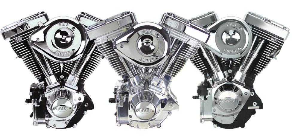

1 Owners Manual S&S V-Series Engines
2 DISCLAIMER: S&S parts are designed for high performance, closed course, racing applications and are intended for the very experienced rider only. The installation of S&S parts may void or adversely effect your factory warranty. In addition such installation and use may violate certain federal, state, and local laws, rules and ordinances as well as other laws when used on motor vehicles used on public highways, especially in states where pollution laws may apply. Always check federal, state, and local laws before modifying your motorcycle. It is the sole and exclusive responsibility of the user to determine the suitability of the product for his or her use, and the user shall assume all legal, personal injury risk and liability and all other obligations, duties, and risks associated therewith. The words Harley, Harley-Davidson, H-D, Sportster, Evolution, and all H-D part numbers and model designations are used in reference only. S&S Cycle is not associated with Harley-Davidson, Inc. SAFE INSTALLATION AND OPERATION RULES: Before installing your new S&S part it is your responsibility to read and follow the installation and maintenance procedures in these instructions and follow the basic rules below for your personal safety. Gasoline is extremely flammable and explosive under certain conditions and toxic when breathed. Do not smoke. Perform installation in a well ventilated area away from open flames or sparks. If motorcycle has been running, wait until engine and exhaust pipes have cooled down to avoid getting burned before performing any installation steps. Before performing any installation steps disconnect battery to eliminate potential sparks and inadvertent engagement of starter while working on electrical components. Read instructions thoroughly and carefully so all procedures are completely understood before performing any installation steps. Contact S&S with any questions you may have if any steps are unclear or any abnormalities occur during installation or operation of motorcycle with a S&S part on it. Consult an appropriate service manual for your motorcycle for correct disassembly and reassembly procedures for any parts that need to be removed to facilitate installation. Use good judgment when performing installation and operating motorcycle. Good judgment begins with a clear head. Don t let alcohol, drugs or fatigue impair your judgment. Start installation when you are fresh. Be sure all federal, state and local laws are obeyed with the installation. For optimum performance and safety and to minimize potential damage to carb or other components, use all mounting hardware that is provided and follow all installation instructions. Motorcycle exhaust fumes are toxic and poisonous and must not be breathed. Run motorcycle in a well ventilated area where fumes can dissipate. WARRANTY: All S&S parts are guaranteed to the original purchaser to be free of manufacturing defects in materials and workmanship for a period of twelve (12) months from the date of purchase. Merchandise that fails to conform to these conditions will be repaired or replaced at S&S s option if the parts are returned to us by the purchaser within the 12 month warranty period or within 10 days thereafter. In the event warranty service is required, the original purchaser must call or write S&S immediately with the problem. Some problems can be rectified by a telephone call and need no further course of action. A part that is suspect of being defective must not be replaced by a Dealer without prior authorization from S&S. If it is deemed necessary for S&S to make an evaluation to determine whether the part was defective, a return authorization number must be obtained from S&S. The parts must be packaged properly so as to not cause further damage and be returned prepaid to S&S with a copy of the original invoice of purchase and a detailed letter outlining the nature of the problem, how the part was used and the circumstances at the time of failure. If after an evaluation has been made by S&S and the part was found to be defective, repair, replacement, or refund will be granted.
3 ADDITIONAL WARRANTY PROVISIONS: (1) S&S shall have no obligation in the event an S&S part is modified by any other person or organization. (2) S&S shall have no obligation if an S&S part becomes defective in whole or in part as a result of improper installation, improper maintenance, improper use, abnormal operation, or any other misuse or mistreatment of the S&S part. (3) S&S shall not be liable for any consequential or incidental damages resulting from the failure of an S&S part, the breach of any warranties, the failure to deliver, delay in delivery, delivery in non-conforming condition, or for any other breach of contract or duty between S&S and a customer. (4) S&S parts are designed exclusively for use in Harley-Davidson and other American v-twin motorcycles. S&S shall have no warranty or liability obligation if an S&S part is used in any other application. Table of Contents: Introduction... 2 Engine Installation... 2 Oil Line Hook up... 2 Oil Recommendations... 2 General Break-in Procedure... 5 Tune Up Information... 7 Super Stock & IST Ignition Systems... 7 EFI Information... 7 Starting Procedure... 8 Super E & G Carburetor Tuning Guide... 9 Engine Service Intervals...12 Engine Specifications Engine Dimensions...14 Torque Specifications...16 Specifications and Wear Limits... 17
4 INTRODUCTION The S&S engine you have purchased is an air-cooled, v-twin. It is designed to offer Proven Performance and reliability. Specifications for the 31 2", 35 8", 4", and 41/8" bore engines are found in this manual. We have covered the most popular configurations, 80ci, 96ci, 111ci, and 124ci, based on their original S&S production designs. Some changes may have been made over time as these engines have been in production for a number of years. The specifications in this manual are based on the most recent production specifications. ENGINE INSTALLATION The procedure for installing an S&S engine is basically the same as outlined in the factory service manual for the model of motorcycle the engine is being installed in. However, S&S engines are sometimes taller then a stock engine so the installer must check to make sure there is adequate clearance between the engine and all chassis components including the frame and fuel tanks. An upgraded clutch should also be considered, since the S&S engine will produce more power than the stock engine it is replacing. OIL LINE HOOK-UP The following diagrams show how the crankcase breather and oil lines should be hooked up for S&S V-Series engines. Note most 41/8" bore engines have a use a vacuum breather system Viscosity SAE 20W50 Above SAE 50 Above SAE 25W60 Above 80 SAE 60 Above 80 Ambient Temperature ( F) OIL RECOMMENDATIONS S&S recommends synthetic engine oil such as S&S Premium Synthetic 20W50. However a premium petroleum based engine oil such as S&S Heavy Duty 20W50 or 25W60 is acceptable. Regardless of what type of oil you select, be sure to use only oil specifically designated for use in an air-cooled motorcycle, and select the viscosity suggested for the temperature range you will be operating your motorcycle in. The oil filter used on an S&S V-Series engine should be rated at 24 microns. Spin-on filters should not have an anti-drain back valve. S&S filters are available to replace Harley-Davidson # A and A. The S&S part numbers are and OIL LINE HOOK-UP V-SERIES 2 3
 is used, which will result in a higher octane requirement of about 96.")
5 OIL LINE HOOK-UP FOR V-SERIES WITH VACUUM BREATHING 4 FUEL REQUIREMENTS The gasoline used in your engine should have a US octane rating of 91 or higher. The United States uses the method of octane rating. In many countries outside the United States, the RON (Research Octane Number) is used, which will result in a higher octane requirement of about 96. GENERAL BREAK-IN NOTES Remember that these are air-cooled engines. Sufficient air movement is required to keep engine temperatures within safe operating limits. Avoid heavy traffic and congestion or extended idle periods whenever possible. S&S v-twin performance engines are designed for, and happiest when running between at normal highway speeds. Today s heavier bikes and taller gearing can easily push a high performance engine into a lugging condition which increases loads on engine components, causes detonation, builds excessive heat, and increases fuel consumption. If the engine does not accelerate easily when given some throttle, downshift to a lower gear. S&S engines benefit from a warm-up period any time they are started, allow engine to reach operating temperature before being subjected to heavy loads or quick throttle revs. OWNERS MANUAL S&S V-SERIES ENGINES BREAK-IN OIL CONSIDERATIONS. Either petroleum or synthetic oil designed for air-cooled v-twin engines can be used during the break-in period and during normal use. If preferred, petroleum oil can be used for the break-in period, after which, the engine can be changed over to synthetic oil. BREAK-IN PROCEDURE 1. Initial start up. Run engine approximately one minute at RPM. DO NOT crack throttle or subject to any loads during this period as head gaskets are susceptible to failure at this time. During this time, check to see that oil pressure is normal, that oil is returning the oil tank, and that no leaks exist. 2. Shut off engine and thoroughly check for any leaks or other problems. Let engine cool to the touch. 3. After engine has cooled, start up again and allow the motor to build some heat. Engine should be run no longer than three to four minutes. When the cylinders become warm/hot to the touch (approximately 150 F) shut the motor down and let it cool to room temp. Follow the same cautions as for the initial start-up, and continue to check for problems. 4. First 50 Miles: a. Street: Ride normally, do not lug the engine. Avoid high heat conditions and vary the RPM while riding. No stop and go traffic, extended idle periods, or high load or high RPM conditions. Max of 3,500 RPM or 60 MPH. b. Dyno: A chassis dynamometer can be used to put the first 50 miles on a new engine. See the notes and procedure below for chassis dyno break-in. 5
6 Miles: Ride normally, do not lug the engine. Avoid high heat conditions, no stop and go traffic or extended idle periods. Limited short bursts of throttle can aid in ring seating from this point forward during the break-in, but avoid continuous high speed or load conditions. Max of 4,250 RPM/70 MPH Miles: Avoid lugging the engine and high heat conditions. Max of 5,000 RPM. Change oil at 500 miles ,000 miles: Ride bike normally, but avoid continuous high load operation and high heat conditions. 8. From 1,000 miles on: Break-in is complete, enjoy! NOTES FOR COMPLETING INITIAL 50 MILE BREAK-IN AND INITIAL TUNING ON A CHASSIS DYNO When running the bike on the dyno it is critical that engine temperatures are monitored, AFR is kept between and the engine is not overheated. Fans must be used to keep the engine cool. When tuning under higher loads stop regularly and allow the engine to cool. A load must be placed on the engine to properly seat the rings. Running a new engine continually with no load will result in cylinder glazing and poor ring seal. The engine should be loaded to simulate close to the weight of the bike, a load of 10 15% on a Dyno jet 250i is usually sufficient. It is not recommended to use an inertia only dyno to break-in an engine as no load can be placed on the engine. Initial tuning on the engine can be completed during the initial 50 miles of dyno break-in. It is recommended the engine be run on the 6 street for a minimum of 500 miles prior to completing tuning at full power. Monitor engine temperature during tuning to ensure the engine is not overheated. DYNO BREAK-IN PROCEDURE (FIRST 50 MILES) 1. Follow the same procedure outlined above for initial start-up and heat cycling the engine. 2. Run the bike for 25 miles on the dyno under varying speeds and loads while going up and down through the gears. Keep engine RPM below 3,500 RPM but do not lug the engine. The dyno must be operated so the engine runs under a load roughly equal to the power needed to move the bike down the road, this would be about 12 hp at 55 MPH. Keep engine head temperatures below 200 F at the temp sensor or surface of the head. Stop and cool the engine if needed. 3. Allow the engine to cool down to room temperature. 4. Run the bike for 25 more miles (50 miles total) under varying speeds, loads, and gears as before. Make sure there is some load on the engine. Keep engine speed below 4,250 RPM but do not lug the engine. Limited short bursts of throttle can aid in ring seating as long as the calibration/tune keeps the AFR in control. Keep engine head temperatures below 225 F at the temp sensor or surface of the head. 5. After the first 50 miles on the dyno, it is recommended the normal break-in schedule be followed under normal riding conditions on the street. See Step 5 under BREAK-IN PROCEDURE. TUNE UP INFORMATION S&S 4" bore and smaller V-Series engines come from the factory with Champion RN12YC 14mm long reach spark plugs (S&S PN ). 4-1/8" bore engines come from the factory with Champion RA8HC 12mm spark plugs (S&S PN ). All spark plugs should be gapped between.038- and.042-inch. If you are not using an S&S ignition system, refer to your ignition manufacturer for any additional recommendations. IGNITION SYSTEM Carbureted S&S V-Series engines come from the factory with either an S&S Super Stock or IST ignition system installed. Fuel injected engines are equipped with an S&S VFI module. S&S Super Stock ignition modules are factory programmed for the specific engine they are intended for. In addition the module is installed and timed to S&S specified timing. Changing the timing or removing the Super Stock ignition may void your warranty. S&S IST ignition systems employ a knock sensor to automatically optimize ignition timing and protect your engine from damage. Removing the IST ignition may void your warranty. Ignition timing in S&S fuel injected engines, is controlled by the S&S VFI module. The calibration file supplied by S&S for the particular engine contains ignition timing curves. If the ignition curve is modified or if another fuel injection module is used, the engine warranty may be voided. If you choose to install another ignition system, make sure that the total ignition advance is set according to the specifications in this chart. If the ignition system has a rev limiter, make sure it is set no higher than 6200 rpm.. Engine Total Advance, VOES Grounded (deg BTDC)* Max Advance, Wide Open Throttle (WOT) RPM Max WOT V V V V V V If you choose to install another EFI module on a fuel injected V124 engine, the following ignition table should be used as a guide for ignition advance under various conditions EFI Ignition Table - S&S V124, 10.8:1 CR, 640 Cam RPM WOT Cruise Idle/Decel
7 START-UP ENGINES EQUIPPED WITH S&S SUPER E OR G CARBURETOR 1. S&S Super E & G carburetors have a mixture enrichment/fast idle lever used to aide in cold starts and help during the warm-up period. Do not ride the motorcycle with the lever engaged. 2. Turn the fuel supply valve on, wait a moment to make sure the carburetor bowl is full, and twist the throttle twice to prime the carburetor starting in extremely cold weather may require additional priming. 3. Pull the fast idle lever up, turn on the ignition and press the start button or kick the engine through. 4. If the engine does not start after several kicks or five seconds of cranking, shut the ignition off for 15 seconds to let the starter cool. 5. Open the throttle slightly and press the starter button or kick the engine through again. It may be necessary to re-prime the engine. If the engine kicks back, the throttle may be opened too far. 6. Once the engine is running, use the fast idle lever to maintain the proper engine speed required during warm-up. 7. When the engine has warmed up enough to idle without the enrichment system, disengage the fast idle lever. The fast idle lever is not required to restart a hot engine. INITIAL START UP WITH IST IGNITION 1. Start the motorcycle up as outlined above. 2. The IST ignition comes with a general ignition map that will allow the engine to be started and run. Within 3 to 5 hours of operation the IST module will optimize this map for your engine, based on 8 data from the knock sensor and other sensors. 3. Ride the motorcycle as you would normally, being sure to include hills, highway speeds (for at least 20 minutes at a time) and around town. Be sure to use the throttle in as many settings as possible without going past the suggested break-in procedures! 4. Once the engine is completely broken in, the IST will be tuned to optimize the engine s performance. 5. Do not run the engine on a dyno until the IST has had time to tune itself to your engine. START-UP ENGINES EQUIPPED THE VARIABLE FUEL INJECTION (VFI) 1. Turn the ignition and kill switches on. Listen for the fuel pump as it pressurizes. 2. Do not twist the throttle open to prime the system. 3. Press the starter button and let engine crank over do not twist the throttle. If the engine is extremely hard to start hot or cold contact the S&S Tech Line or visit for the location of the closest VFI Tuning Center. SUPER E & G CARBURETOR TUNING GUIDE 1. Verify carburetor is set to stock settings: a. Idle mixture screw, 11/4 turns from lightly seated. b. Idle speed screw, 1 2 turn clockwise from engagement point. c. Accelerator adjustment screw, two turns counter-clockwise from seated. 2. Start bike, bring to operating temperature. 3. Set idle speed adjusting screw, clockwise to increase RPM, counter-clockwise to decrease RPM. Idle RPM range should be 950 to 1050 RPMs. 4. Adjust idle mixture by turning idle mixture screw slowly clockwise until the engine runs poorly. Note position. Slowly turn the screw counter-clockwise until it starts to stumble. Note position. Set the idle mixture screw halfway between the positions, or at the strongest idle. Inconsistent idle may indicate a manifold leak. 5. With engine idling, turn accelerator adjustment screw clockwise until it lightly seats. Snap throttle open engine should stumble. Turn screw counter-clockwise 1/4 or 1 2 of a turn at a time, until engine responds to throttle twist with smooth, quick response. 6. Ride motorcycle in various RPM ranges, and then try to maintain a consistent 40- to 50-MPH. If the engine has a flat spot, or is popping/sneezing in the air cleaner, it can indicate a lean condition. If you notice stumbling or sputtering, it can indicate a rich condition. 7. Low RPM operation is controlled by the intermediate jet (#11 on following page). If sneezing or popping is experienced below approximately 3000 RPMs the intermediate jet must be replaced with a larger sized (richer) jet. If the engine does not run smoothly at low speeds, fouls plugs, blows black smoke or gets bad gas mileage a smaller (leaner) intermediate jet needs to be installed. Always readjust the idle mixture (#2) and idle speed (#1) screws after making a jet change. 8. To test the main jet, do a roll-on from 50-MPH to 70-MPH in 3rd gear. If the engine backfires or breaks up in the carb, increase the main jet size.004". If the engine is flat or will not accelerate, decrease the main jet by.004". 9. Since 2004 S&S shorty carbs have been fitted with an adjustable main jet air bleed (#13). Changing this jet to a larger size will delay the signal to the main jet, therefore aiding with high speed tuning as described in step 8. This also aides with tuning an engine that is fitted with an exhaust system that is not intended for high performance. The air bleed uses main jets, the stock size is 40. If it needs to be changed the range is normally 50 to NOTE: Drag or straight pipes, especially large diameter or long designs, can prevent you from obtaining optimum carburetor performance. 11. If the S&S teardrop air cleaner is being replaced with an aftermarket air cleaner, be sure to remove the auxiliary bowl vent screw (#14). Never use a velocity stack on a street driven motorcycle! Poor throttle response will be experienced. 12. Always be sure to attach the hose to the overflow tube fitting (#6) and route it toward the back of the engine. 9
8 Approximate Jetting For S&S Super E & G Carburetors Displacement 883cc 74 88ci ci ci Intermediate Jet Main Jet These jetting recommendations are a starting point only. Re-jet carb for best performance Idle Speed Screw Idle Mixture Screw 3- Accelerator Pump Adjustment Screw Enrichment Device 5- Serial Number 6- Overflow Tube Fitting 7- Fuel Inlet Accelerator Pump Pushrod 11- Intermediate Jet 12- Main Jet 8- Bowl Vent Hole 13- Main Jet Air Bleed Bowl Plug 14- Auxiliary Bowl Vent Plug 11
9 ENGINE SERVICE INTERVALS Item Interval Engine Oil & Filter Change at 500, 2,500 miles (80, 800, 4,000 kilometers), every 2,500 miles (4,000 kilometers) thereafter 1. Air Cleaner Element Inspect at 50 and 500 miles (80 and 800 kilometers), every 2,500 miles (4,000 kilometers) thereafter 2. Replace every 5,000 miles (8,000 kilometers). Tappet Oil Screen Petcock, Lines, & Fittings, Vacuum Lines Fuel Tank Filter Screen & In-Line Fuel Filter (If used) Engine Idle Speed Operation of Throttle & Enrichment Device Controls Spark Plugs Ignition Timing Engine Mounts External Fasteners Except Engine Head Bolts Inspect every 2,500 miles (4,000 kilometers). Replace every 5,000 miles (8,000 kilometers). Inspect at 50 and 500 miles (80 and 800 kilometers), every 2,500 miles (4,000 kilometers) thereafter. Inspect every 5,000 miles (8,000 kilometers). Adjust as required. Inspect at 500 miles (800 kilometers) and every 2,500 miles (4,000 kilometers) thereafter. Inspect every 5,000 miles (8,000 kilometers). Replace every 10,000 miles (16,000 kilometers) or as needed. Inspect every 5,000 miles (8,000 kilometers). Inspect at 500 miles (800 kilometers) and every 5,000 miles (8,000 kilometers) thereafter. Re-torque at 500 miles (800 kilometers) and every 5,000 miles (8,000 kilometers) thereafter. 1- S&S recommends that petroleum-based oil not specifically formulated for motorcycles should be changed every 1,000 miles (1,600 kilometers) after the break-in period. 2- Replace more frequently if required or if engine is operated in a dusty environment. ENGINE SPECIFICATIONS The following chart contains information about a number of S&S engines covered by this owners manual. Engine Displacement Bore Stroke CR Cam Tappets Fuel System Ignition System V80 80" 31/2" 41/4" 8.4:1 508 Hydraulic Super E or None Super Stock or None V96 96" 35/8" 45/8" 9.5:1 585 Hydraulic w/hl2t Super E Super Stock or IST V96 TÜV 96" 35/8" 45/8" 10.1:1 520 Hydraulic Super E IST V " 41/8" 41/8" 9.8:1 585 Hydraulic w/hl2t Super E Super Stock or IST V113 TÜV 113" 4" 41/2" 10.1:1 547 Hydraulic w/hl2t Super G IST V " 41/8" 45/8" 10.8:1 640 Hydraulic w/hl2t Super G or VFI Super Stock, IST, or VFI V124 TÜV 124" 41/8" 45/8" 9.5:1 547 Hydraulic w/hl2t Super G IST 12 13

10 ENGINE DIMENSIONS Some S&S engines are taller than stock engines. These diagrams show the dimensions of various S&S engines. This information will be most useful to customers building custom motorcycles with after market frames. Engine A B 14 V " " V " " V " " V96 TUV " " V " " V " " V " " V113 TUV " " V " " V124 TUV " " Front of Engine Nothing lasts forever, and despite the superior materials and design of the components in your S&S engine, some day it will need to be serviced. Who better to repair your engine, than the technicians at the company where it was made? To obtain factory service for your S&S engine, have your S&S dealer contact the S&S Service & Speed Center. To find an S&S dealer in your area go to the S&S Dealer Locator at CHARGING SYSTEM NOTE - If you are going to use a 45 amp alternator you must install a S&S spacer (PN ). If you do not use this spacer the rotor could bottom out against the case when the sprocket shaft nut is tightened. OWNERS MANUAL S&S V-SERIES ENGINES IMPORTANT INFORMATION S&S engines are not recommended for inexperienced riders because the increased performance requires a higher level of riding skill. Do not lug your S&S engine. This is a high performance engine, designed to produce excellent horsepower at higher RPM. It was not well suited to pull heavy loads at low RPM. We recommend that the engine not be operated below 2500 RPM for extended periods of time. Shift to a lower gear to keep the engine speed up when traveling at lower speeds. Your S&S Engine is air cooled, which means that it depends on air moving across the cooling fins to keep it from over heating. Do not allow your engine to idle for extended periods of time. Avoid stop and go traffic or any other situation where the motorcycle is not moving while the engine is running. To avoid engine damage, do not operate the engine above 6200 RPM. SERVICE SPECIFICATIONS FOR S&S ENGINES For the most part if an S&S engine requires service, a qualified mechanic who services Harley-Davidson engines can do the work. However the specifications for S&S engines are somewhat different. These charts are provided for reference. For more detailed information about any specific S&S component, installation instructions are available for free download from the S&S website 15
11 TORQUE SPECIFICATIONS Item Torque Recommended Rocker Box 1 4" in-lbs Loctite 243 Rocker Box base 5 16" ft-lbs Loctite 243 Rocker arm support plate ft-lbs Loctite 243 Cylinder head bolts 8 ft-lbs, 18 ftlbs, 90 Oil threads Cylinder studs 10 ft-lbs Loctite 272 Crankcase fasteners ft-lbs (1 4) ft-lbs (5 16) Piston oilers 25 in-lbs Loctite 243 Pinion nut 50 ft-lbs Loctite 272 Tappet guide fasteners in-lbs Loctite 243 Pushrod locknuts in-lbs Gear cover fasteners in-lbs Loctite 243 Timing hole plug 120 in-lbs Anti-seize Oil pump cover/mounting bolts (4) Oil pump top mounting (2) in-lbs 60 in-lbs Intake manifold to head 16 ft-lbs Loctite 243 Intake manifold to carb 18 ft-lbs Loctite 243 Item Torque Recommended Compression releases ft-lbs Anti-seize Exhaust flange to head ft-lbs Anti-seize Head temp sensor ft-lbs Anti-seize Knock sensor 11 ft-lbs Anti-seize Crank position sensor in-lbs Spark plug ft-lbs Anti-seize NOTE: 12 in-lbs equals 1 ft-lbs SPECIFICATIONS & WEAR LIMITS Description Specification Wear Limit Rocker Arm Shaft in bushing.0007"-.0018".0035" Bushing fit in rocker arm (press).0012"-.0032" <.0012" Rocker arm endplay.001"-.012" Cylinder Head Valve to guide fit intake.0012"-.0020".0035" Valve to guide fit exhaust.0017"-.0025".0040" Valve guide in head (press).0015"-.0030" <.0015" Valve seat in head (press).0050"-.0070" <.0050" Seat width intake.031".041" Seat width exhaust.047".057" Valve stem protrusion 2.045"-2.060" 2.080" Pistons Fit in cylinder.002"-.0026".0055" Compression ring gap.017"-.026".030" Oil ring gap.010"-.040".050" Description Specification Wear Limit Connecting Rods Side play.006"-.036".040" Wristpin in rod.0005"-.001".002" Crankpin running clearance.001"-.0012".002" Flywheels Run out at bearing.0005"-.001".006" Timken endplay.001"-.005".005" Pinion bearing fit.0004"-.001".002" Cam Chest Breather gear endplay.005"-.015".016" Breather clearance.0015"-.003".004" Camshaft in bushing.0007"-.002".0035" Camshaft endplay.005"-.015".016" Pinion shaft in bushing.001"-.0025".0035" Bushing fit in gear cover (press).0007"-.0023" <.0006" Oil pump shaft.0005"-.0025".0035" Lifters Lifter fit in guide.0006"-.0017".0022" 16 17
12 OWNERS MANUAL NOTES
13 S&S Cycle, Inc County Hwy G Viola, WI Phone: Fax: Technical Service Phone: TECH (8324) Technical Service sstech@sscycle.com /02/15 Copyright 2015 by S&S Cycle, Inc. All rights reserved. Printed in the U.S.A.
Owners Manual. S&S X-Wedge Engines
 Owners Manual S&S X-Wedge Engines DISCLAIMER: S&S parts are designed for high performance, closed course, racing applications and are intended for the very experienced rider only. The installation of S&S
S&S. Installation Instructions: Pistons for Harley-Davidson CVO 110 Engines. Instruction Copyright 2015 by S&S Cycle, Inc.
 Instruction 510-0369 02-27-15 Copyright 2015 by S&S Cycle, Inc. All rights reserved. Printed in the U.S.A. S&S Cycle, Inc. 14025 Cty Hwy G PO Box 215 Viola, Wisconsin 54664 Phone: 608-627-1497 Fax: 608-627-1488
S&S. Installation Instructions for S&S VFI Knock Sensor Kit for 2001-'07 Delphi Style VFI Module (with USB) Instruction
 Instruction") Instruction 106-1544 9-28-07 Copyright 2007 by S&S Cycle, Inc. All rights reserved. Printed in the U.S.A. S&S Cycle, Inc. 235 Causeway Blvd. La Crosse, Wisconsin 54603 Phone: 608-627-1497 Fax: 608-627-1488
Instruction 106-1544 9-28-07 Copyright 2007 by S&S Cycle, Inc. All rights reserved. Printed in the U.S.A. S&S Cycle, Inc. 235 Causeway Blvd. La Crosse, Wisconsin 54603 Phone: 608-627-1497 Fax: 608-627-1488
S&S. Installation Instructions: S&S Stealth Air Cleaner Covers. Instruction IMPORTANT NOTICE:
 Instruction 510-0226 09-03-13 Copyright 2013 by S&S Cycle, Inc. All rights reserved. Printed in the U.S.A. S&S Cycle, Inc. 14025 Cty Hwy G PO Box 215 Viola, Wisconsin 54664 Phone: 608-627-1497 Fax: 608-627-1488
S&S. Installation Instructions for S&S Single Bore Tuned Induction Kit for 2008-Up Touring Models with Electronic Throttle Control
 Instruction 106-4891 06-24-14 Copyright 2009, 2014 by S&S Cycle, Inc. All rights reserved. Printed in the U.S.A. S&S Cycle, Inc. 14025 County Highway G PO Box 215 Viola, Wisconsin 54664 Phone: 608-627-1497
S&S. S&S Oil Supply Line Installation Kit PN (For Harley-Davidson Dyna Models) PN (For FLT Models)
 PN (For FLT Models)") Instruction 510-0039 03-07-13 Copyright 2011, 2013 by S&S Cycle, Inc. All rights reserved. Printed in the U.S.A. S&S Cycle, Inc. 14025 County Highway G PO Box 215 Viola, Wisconsin 54664 Phone: 608-627-1497
Instruction 510-0039 03-07-13 Copyright 2011, 2013 by S&S Cycle, Inc. All rights reserved. Printed in the U.S.A. S&S Cycle, Inc. 14025 County Highway G PO Box 215 Viola, Wisconsin 54664 Phone: 608-627-1497
S&S. Cycle, Inc. Installation Instructions: Cam Support Plate for 2017-up M8 Models. Instruction
 Instruction 0-0 0-0- Version 0 by S&S Cycle, Inc. All rights reserved. Printed in the U.S.A. S&S Cycle, Inc. 0 Cty Hwy G Viola, Wisconsin Phone: 0-- Fax: 0-- Technical Service Phone: 0--TECH () Technical
S&S. Instruction Copyright 2014, Version 4 by S&S Cycle, Inc.
 Instruction 510-0295 10-02-2017 Copyright 2014, 2016. 2017 Version 4 by S&S Cycle, Inc. All rights reserved. Printed in the U.S.A. S&S Cycle, Inc. 14025 Cty Hwy G PO Box 215 Viola, Wisconsin 54664 Phone:
S&S. Installation Instructions for S&S Sealed Air Cleaner. Instruction IMPORTANT NOTICE:
 Instruction 106-2707 11-20-08 Copyright 2008 by S&S Cycle, Inc. All rights reserved. Printed in the U.S.A. S&S Cycle, Inc. 235 Causeway Blvd. La Crosse, Wisconsin 54603 Phone: 608-627-1497 Fax: 608-627-1488
S&S. Installation Instructions: S&S Billet Air Cleaner Kit PN for Victory Motorcycles. Instruction IMPORTANT NOTICE:
 Instruction 106-1330 06-23-10 Copyright 2008, 2009, & 2010 by S&S Cycle, Inc. All rights reserved. Printed in the U.S.A. S&S Cycle, Inc. 14025 Cty Hwy G PO Box 215 Viola, Wisconsin 54664 Phone: 608-627-1497
Cycle, Inc. S&S. Installation Instructions: Chain Drive Camshaft for 2017 Harley-Davidson Milwaukee Eight Engines. Instruction
 Instruction 0-067 0-8-07 Version Copyright 07 by S&S Cycle, Inc. All rights reserved. Printed in the U.S.A. S&S Cycle, Inc. 0 Cty Hwy G Viola, Wisconsin 66 Phone: 608-67-97 Fax: 608-67-88 Technical Service
S&S. Instruction IMPORTANT NOTICE:
 Instruction 106-4426 10-31-08 Copyright 2008 by S&S Cycle, Inc. All rights reserved. Printed in the U.S.A. S&S Cycle, Inc. 235 Causeway Blvd. La Crosse, Wisconsin 54603 Phone: 608-627-1497 Fax: 608-627-1488
Installation Instructions for S&S Single Bore Throttle Bodies
 Instruction 1-1270 12-29-1 Rev 2 Copyright 2009, 201 by S&S Cycle, Inc. All rights reserved. Printed in the U.S.A. S&S Cycle, Inc. 1402 Cty Hwy G PO Box 21 Viola, Wisconsin 4664 Phone: 608-627-1497 Fax:
Cycle, Inc Cty Hwy G Viola, Wisconsin Phone: Fax:
 Instruction 510-0414 11-14-16 Version 3 Copyright 016 by S&S Cycle, Inc. All rights reserved. Printed in the U.S.A. S&S Cycle, Inc. 1405 Cty Hwy G Viola, Wisconsin 54664 Phone: 608-67-1497 Fax: 608-67-1488
Installation Instructions for S&S Single Bore Throttle Bodies
 Instruction 51-1239 12-29-15 Rev 2 Copyright 2009, 2015 by S&S Cycle, Inc. All rights reserved. Printed in the U.S.A. S&S Cycle, Inc. 14025 Cty Hwy G PO Box 215 Viola, Wisconsin 54664 Phone: 608-627-1497
Cycle, Inc. 235 Causeway Blvd. La Crosse, Wisconsin 54603
 Instruction 51-1196 4-7-06 Copyright 2001, 2004, 2006 by S&S Cycle, Inc. All rights reserved. Printed in the U.S.A. S&S Cycle, Inc. 235 Causeway Blvd. La Crosse, Wisconsin 54603 Phone: 608-627-1497 Fax:
Cycle, Inc Cty Hwy G Viola, Wisconsin Phone: Fax:
 Instruction 510-0481 09-10-18 Version 1 2018 by S&S Cycle, Inc. All rights reserved. Printed in the U.S.A. S&S Cycle, Inc. 14025 Cty Hwy G Viola, Wisconsin 54664 Phone: 608-627-1497 Fax: 608-627-1488 Technical
Lloydz Indian Air Filter w/custom Cover
 IMC-215/220-I 8.28.2015 Lloydz Motor Workz 25 railroad Ave PO Box 11 Pine Bush, NY 12566 Lloydz Indian Air Filter w/custom Cover VICTORY/INDIAN WARRANTY POLICY: Lloydz Indian Air Filter is intended for
s&s e e, 1~. 235 Causeway Blvd. La Crosse, Wisconsin 54603
 Instruction 51-121 6 5-4-06 Copyright o 2005, 2006 by S&S Cycle, Inc. All rights reserved. Printed in the U.S.A. s&s e e, 1~. 235 Causeway Blvd. La Crosse, Wisconsin 54603 Phone: 608-627-1497 Fax: 608-627-1488
From The Track... To The Street!
 Instruction Sheet For JIMS Twin Cam Flywheel Assemblies & Big Bore Kit For the following part numbers 1881, 1882, 1883, 1884, 1886, 1888, 1937, 1938, 1941, 1942, 1943, 1944, 1945, 1946, 1957, 1958, 1959,
S&S. S&S V-Series California Engine Owner's Manual. Instruction IMPORTANT NOTICE:
 Instruction 510-0231 12-4-13 Copyright 2014 by S&S Cycle, Inc. All rights reserved. Printed in the U.S.A. S&S Cycle, Inc. 235 Causeway Blvd. La Crosse, Wisconsin 54603 Phone: 608-627-1497 Fax: 608-627-1488
S&S Cycle, Inc County Hwy. G Box 215 Viola, Wisconsin U.S.A.
 Instruction Sheet 51-1046 1-28-03 Copyright 1999, 2003 by S&S Cycle, Inc. All rights reserved. Printed in the U.S.A. S&S Cycle, Inc. 14025 County Hwy. G Box 215 Viola, Wisconsin 54664 U.S.A. Phone 608-627-2080
S&S. Instruction IMPORTANT NOTICE:
 Instruction 106-6415 09-19-12 Copyright 2009, 2011, 2012 by S&S Cycle, Inc. All rights reserved. Printed in the U.S.A. S&S Cycle, Inc. 14025 Cty Hwy G PO Box 215 Viola, Wisconsin 54664 Phone: 608-627-1497
Cycle, Inc. 235 Causeway Blvd. La Crosse, Wisconsin 54603
 Instruction 51-1047 4-8-06 Copyright 2003, 2004, 2006 by S&S Cycle, Inc. All rights reserved. Printed in the U.S.A. S&S Cycle, Inc. 235 Causeway Blvd. La Crosse, Wisconsin 54603 Phone: 608-627-1497 Fax:
Quality Work with Quailty People
 Manuafactured by : DRM Industries Corp. Quality Work with Quailty People 231 W. Adams St. PO Box 758 Lake Delton, WI 53959 Call for Customer Sevice at 608-254-8158 7am to 4pm Monday - Friday Email: framelock@drmindustries.com
S&S. Installation Instructions: S&S Standard and Easy Start Gear Drive Cams for Harley-Davidson Twin Cam 88 Engines. Instruction
 Instruction 106-5893 11-18-09 Copyright 2009 by S&S Cycle, Inc. All rights reserved. Printed in the U.S.A. S&S Cycle, Inc. 14025 Cty Hwy G PO Box 215 Viola, Wisconsin 54664 Phone: 608-627-1497 Fax: 608-627-1488
ASSEMBLY DIAGRAM AND ASSEMBLY REFERENCE ULTIMA OLD SCHOOL 2 BELT DRIVE UNITS
 ASSEMBLY DIAGRAM AND ASSEMBLY REFERENCE ULTIMA OLD SCHOOL 2 BELT DRIVE UNITS BELT DRIVE ASSEMBLIES Part# 58-850 2 Old School Belt Drive Assembly - Polished Part# 58-851 2 Old School Belt Drive Assembly
Cycle, Inc Cty Hwy G PO Box 215 Viola, Wisconsin 54664
 Instruction 51-1116 10-19-11 Copyright 2008, 2011 by S&S Cycle, Inc. All rights reserved. Printed in the U.S.A. S&S Cycle, Inc. 14025 Cty Hwy G PO Box 215 Viola, Wisconsin 54664 Phone: 608-627-1497 Fax:
S&S. Instruction Copyright 2014 by S&S Cycle, Inc. IMPORTANT NOTICE:
 Instruction 510-0251 05-29-14 Copyright 2014 by S&S Cycle, Inc. All rights reserved. Printed in the U.S.A. S&S Cycle, Inc. 14025 Cty Hwy G PO Box 215 Viola, Wisconsin 54664 Phone: 608-627-1497 Fax: 608-627-1488
DYNA EVO & T.C. MODELS 91-05
 ASSEMBLY DIAGRAM AND ASSEMBLY REFERENCE ULTIMA OLD SCHOOL 2 BELT DRIVE UNITS DYNA EVO & T.C. MODELS 91-05 Part # 58-900 2 BELT DRIVE ASSEMBLY REV 1-20-10 ASSEMBLY DIAGRAM AND ASSEMBLY REFERENCE ULTIMA
S&S. Installation Instructions: S&S IST Ignition System for /8" Bore Big Twin Engines. Instruction IMPORTANT NOTICE:
 Instruction 51-1155 04-21-15 Copyright 2009, 2010, & 2012 by S&S Cycle, Inc. All rights reserved. Printed in the U.S.A. S&S Cycle, Inc. 14025 County Highway G Viola, WI 54664 Phone: 608-627-1497 Fax: 608-627-1488
INSIDE YOUR HOLLEY CARBURETOR FUEL INLET SYSTEM
 INSIDE YOUR HOLLEY CARBURETOR The carburetor is quite simply a fuel metering device that operates under the logical and straightforward laws of physics. It has evolved over the years from a very simple
DYNA EVO & T.C. MODELS 91-05
 ASSEMBLY DIAGRAM AND ASSEMBLY REFERENCE ULTIMA OLD SCHOOL 2 BELT DRIVE UNITS DYNA EVO & T.C. MODELS 91-05 Part # 58-900 2 BELT DRIVE ASSEMBLY REV 10-22-14 ASSEMBLY DIAGRAM AND ASSEMBLY REFERENCE ULTIMA
S&S Cycle, Inc County Highway G Box 215 Viola, Wisconsin Phone: Fax:
 Instruction Sheet 51-1010 Revised 5-1-02 Copyright, 2002 by S&S Cycle, Inc. All rights reserved. Printed in the U.S.A. S&S Cycle, Inc. 14025 County Highway G Box 215 Viola, Wisconsin 54664 Phone: 608-627-1497
Cycle, Inc. 235 Causeway Blvd. La Crosse, Wisconsin 54603
 Instruction 51-1160 10-26-06 Copyright, 2003, 2006 by S&S Cycle, Inc. All rights reserved. Printed in the U.S.A. S&S Cycle, Inc. 235 Causeway Blvd. La Crosse, Wisconsin 54603 Phone: 60-627-1497 Fax: 60-627-14
Cycle, Inc. 235 Causeway Blvd. La Crosse, Wisconsin 54603
 Instruction 51-1042 4-6-06 Copyright 1999, 2000, 2005, 2006 by S&S Cycle, Inc. All rights reserved. Printed in the U.S.A. S&S Cycle, Inc. 235 Causeway Blvd. La Crosse, Wisconsin 54603 Phone: 608-627-1497
HSR Carburetor. Total Kits. Installation Instructions. # Evo Big Twin # present Twin Cam
 HSR Carburetor Total Kits Installation Instructions HSR42 Kits: HSR45 Kits: #42-8 84-99 Evo Big Twin #42-19 99 - present Twin Cam #45-2 84-99 Evo Big Twin #45-3 84-99 Evo Big Twin #45-4 99 - present Twin
HSR Carburetor Easy Kits Installation Instructions For Evo Big Twin Kit: # 42-7 Twin Cam Kit: # 42-18
 HSR Carburetor Easy Kits Installation Instructions For Evo Big Twin Kit: # 42-7 Twin Cam Kit: # 42-18 Revised 5/01/01 EK-1 Easy Kit Installation Instructions The HSR series carburetors are precise yet
HSR Carburetor. Total Kits. Installation Instructions. # Evo Big Twin # present Twin Cam
 HSR Carburetor Total Kits Installation Instructions HSR42 Kits: HSR45 Kits: #42-8 84-99 Evo Big Twin #42-19 99 - present Twin Cam #45-2 84-99 Evo Big Twin #45-3 84-99 Evo Big Twin #45-4 99 - present Twin
ACCEL Distributor Model #A557
 FORM 1627 REV1 INSTALLATION INSTRUCTIONS ACCEL Distributor Model #A557 CAUTION: CAREFULLY READ INSTRUCTIONS BEFORE PROCEEDING. NOT LEGAL FOR USE OR SALE ON POLLUTION CONTROLLED VECHICLES OVERVIEW ACCEL
INSTALLATION HYPERCHARGER AIR FILTER KIT 9754
 9754 PARTS INCLUDED 1 Chrome Hypercharger Assembly 1 Support Bracket 1 Breather Hardware Kit, including: 2 1-1/4 Breather Bolts 2 Breather Hoses 4 Shim Washers 1 Twin Cam Breather Kit, Including: 1 Breather
POWER CELL FOR DYNA WITH CLEAN CHROME COVER 562
 POWER CELL FOR DYNA WITH CLEAN CHROME COVER 562 THANK YOU FOR CHOOSING CRUSHER! PROTECT YOURSELF AND OTHERS FROM POTENTIAL INJURY AND PROPERTY DAMAGE OR LOSS. PAY CLOSE ATTENTION TO ALL INSTRUCTIONS, WARNINGS,
INSTALLATION HYPERCHARGER AIR FILTER KIT 9992
 9992 PARTS INCLUDED 1 Chrome Hypercharger Assembly with Chrome Blood Groove Trap Door and Chrome Butterflies 1 Support Bracket 1 Breather Hardware Kit, including: 2 1-1/4 Breather Bolts 2 Breather Hoses
Racing Performance Catalog & Reference Guide Model/Type:
 Version 4/08 Racing Performance Catalog & Reference Guide Model/Type: 124435 8105-01 Table of Contents SAFETY... 1 WORLD FORMULA General Specs...3 Special Tools...3 Torque Specs...3 Racing Specifics...3
S&S. Installation and Jetting Instructions for S&S Super E and G Series "Shorty" Carburetors. Instruction IMPORTANT NOTICE:
 Instruction 51-1012 07-25-12 Copyright 2009, 2010, 2012 by S&S Cycle, Inc. All rights reserved. Printed in the U.S.A. S&S Cycle, Inc. 14025 Cty Hwy G PO Box 215 Viola, Wisconsin 54664 Phone: 608-627-1497
Typical Install Instructions
 Typical Install Instructions Read & understand all steps of these instructions before beginning this installation. WEBER Conversion Kit, VW T-1/2, up to 1835cc 32 / 36 DFEV Weber Carburetor These instructions
S&S. Installation and Jetting Instructions for S&S Super E and G Series "Shorty" Carburetors. Instruction IMPORTANT NOTICE:
 Instruction 51-1012 5-14-10 Copyright 2009, 2010 by S&S Cycle, Inc. All rights reserved. Printed in the U.S.A. S&S Cycle, Inc. 14025 Cty Hwy G PO Box 215 Viola, Wisconsin 54664 Phone: 608-627-1497 Fax:
SE120R SCREAMIN' EAGLE PRO RACE-USE CRATE ENGINE
 -J007 REV. 00-09-08 SE0R SCREAMIN' EAGLE PRO RACE-USE CRATE ENGINE GENERAL Kit Number 90- Models For model fitment information, see the P&A Retail Catalog or the Parts and Accessories section of www.harley-davidson.com
S&S. Installation Instructions: S&S Complete Gear Drive Cam Chest Kit For Harley-Davidson Big Twins
 Instruction 10-00 0-1-01 Copyright 01 Version 1 by S&S Cycle, Inc. All rights reserved. Printed in the U.S.A. S&S Cycle, Inc. 10 Cty Hwy G PO Box 1 Viola, Wisconsin Phone: 0--19 Fax: 0--1 Technical Service
3. INSPECTION/ADJUSTMENT
 3 SERVICE INFORMATION...3-0 FINAL REDUCTION GEAR OIL...3-7 MAINTENANCE SCHEDULE...3-2 DRIVE BELT...3-7 FUEL FILTER...3-3 BRAKE SHOE...3-8 THROTTLE OPERATION...3-3 BRAKE ADJUSTING NUT...3-8 AIR CLEANER...3-4
Reproduction. Not for. Briggsracing.com. CORPORATION Briggs & Stratton Corporation MS /08
 Briggsracing.com MS-5702-4/08 BRIGGS&STRATTON CORPORATION Post office box 702 Milwaukee, WI 53201 USA 414 259 5333 2008 Briggs & Stratton Corporation Version 4/08 Racing Performance Catalog & Reference
carbureted evo press flywheel kits
 carbureted evo press flywheel kits Use on 1970-1984 Shovelhead or 1984 1999 Evolution These instruction are for the following part numbers: 1972,1973,1974,1976,1977,1978, 1979,1980,1981,1982,1983,1984,1985,1986,1987.
CRUSHER MAVERICK 2 INTO 2, BLACK 566
 CRUSHER MAVERICK 2 INTO 2, BLACK 566 THANK YOU FOR CHOOSING CRUSHER! PROTECT YOURSELF AND OTHERS FROM POTENTIAL INJURY AND PROPERTY DAMAGE OR LOSS. PAY CLOSE ATTENTION TO ALL INSTRUCTIONS, WARNINGS, CAUTIONS,
S&S. Installation Instructions: S&S Complete Gear Drive Cam Chest Kit For Harley-Davidson Big Twins
 Instruction 510-0402 05-10-2016 Copyright 2016 Version 1 by S&S Cycle, Inc. All rights reserved. Printed in the U.S.A. S&S Cycle, Inc. 14025 Cty Hwy G PO Box 215 Viola, Wisconsin 54664 Phone: 60-62-14
Installation Instructions: Subaru CS600 & CS600X Long Block Block Assemblies
 Part Number: 20000160, 20000161, 20000162, 20002503, 20002504, 20002505, 20002506, 20003488, 20003489, 20003490, 20007211, 20007212, 20007213, 20007705, 20007706, 20007707, 20007708, 20007709, 20007710,
12. CARBURETOR 12-0 CARBURETOR VITALITY 50
 12 12 CARBURETOR SERVICE INFORMATION (2-STROKE)... 12-2 SERVICE INFORMATION (4-STROKE)... 12-3 THROTTLE VALVE (2-STROKE)... 12-5 CARBURETOR (2-STROKE)... 12-7 AIR SCREW ADJUSTMENT (2-STROKE)... 12-13 REED
5. FUEL SYSTEM FUEL SYSTEM 5-0
 5 FUEL SYSTEM 5-0 SERVICE INFORMATION GENERAL INSTRUCTIONS SERVICE INFORMATION...5-1 CARBURETOR INSTALLATION...5-9 TROUBLESHOOTING...5-1 PILOT SCREW ADJUSTMENT...5-10 CARBURETOR REMOVAL...5-2 AUTO BYSTARTER...5-3
FUEL SYSTEM. Table of Contents. Specifications. Section 3A Fuel Delivery System. Models 6/8/9.9/10/15 CARBURETOR SPECIFICATIONS
 FUEL SYSTEM Section 3A Fuel Delivery System Table of Contents Specifications............................. 3A-1 WMC Carburetor Specifications............. 3A-2 WMC Carburetor Specifications.............
Performer RPM Camshaft/Lifters/Lube Kit CATALOG #7106 MODEL: c.i.d. Ford V8
 Performer RPM Camshaft/Lifters/Lube Kit MODEL: 352-428 c.i.d. Ford V8 PLEASE study these instructions carefully before installing your new camshaft. If you have any questions or problems, do not hesitate
WILD THINGS FUEL INJECTION CONTROLLER 9219
 I N S TA L L AT I O N WILD THINGS FUEL INJECTION CONTROLLER 9219 BY D O B E C K P E R F O R M A N C E FITS: 06-UP SOFTAIL, DRESSER, AND ROAD KING WITH DELPHI FUEL INJECTION Thank you for choosing the Wild
7. FUEL SYSTEM ('04 - '05)
") 7. FUEL SYSTEM ('04 - '05) SYSTEM COMPONENTS 7-2 CARBURETOR DISASSEMBLY 7-81 SERVICE INFORMATION 7-3 CARBURETOR ASSEMBLY 7-14 TROUBLESHOOTING 7-4 CARBURETOR INSTALLATION 7-21 AIR CLEANER HOUSING 7-5 PILOT
7. FUEL SYSTEM ('04 - '05) SYSTEM COMPONENTS 7-2 CARBURETOR DISASSEMBLY 7-81 SERVICE INFORMATION 7-3 CARBURETOR ASSEMBLY 7-14 TROUBLESHOOTING 7-4 CARBURETOR INSTALLATION 7-21 AIR CLEANER HOUSING 7-5 PILOT
NHRA RACING Ford Stock Replacement 735 CFM Class Legal Carburetor P/N
 NHRA RACING Ford Stock Replacement 735 CFM Class Legal Carburetor P/N 0-4609-1 Primary Venturi: 1.375 Secondary Venturi: 1.437 Throttle Bore: 1.750 Service Carburetor Installation and Adjustment Instructions
BAKER CRUISE DRIVE TOP COVER BAKER 1.5 OIL PAN
 BAKER BAKER CRUISE 1.5 DRIVE OIL TOP PAN COVER PN: BD-1.5B Wrinkle Black Highlighted Pan Assembly BD-1.5CVO Granite Highlighted Pan Assembly CVO Models BD-1.5P Show Polished Pan Assembly BD-1.5C Chrome
V PN 4-155N1-K (N1 Shift Drum Kit For Ratchet Style Top Covers) PAGE 1 COVER
 PAGE 1 COVER") BAKER 4-SPEED CRUISE N1 DRIVE SHIFT TOP DRUM COVER KIT V3-05222014 PN 4-155N1-K (N1 Shift Drum Kit For Ratchet Style Top Covers) PAGE 1 COVER FEATURES Tired of stalling your jockey shift bike while trying
BAKER 4-SPEED CRUISE N1 DRIVE SHIFT TOP DRUM COVER KIT V3-05222014 PN 4-155N1-K (N1 Shift Drum Kit For Ratchet Style Top Covers) PAGE 1 COVER FEATURES Tired of stalling your jockey shift bike while trying
TOURING Models
 P/N FI-1252HPST Patent Numbers: 7,000,599 & 7,124,742 Electronic Jet Kit Instructions Thank you for choosing the Techlusion Electronic Jet Kit, the TFI. This TFI model is ONLY usable for the following
S&S Cycle, Inc. General Flywheel Instructions
 Instruction sheet No. 2002 Revised 6-29-99 Copyright 1995 by S&S Cycle, Inc. All rights reserved. Printed in the U.S.A. SAFE INSTALLATION AND OPERATION RULES: Before installing your new S&S flywheels it
3. INSPECTION/ADJUSTMENT
 SERVICE INFORMATION...3-0 FINAL REDUCTION GEAR OIL...3-7 MAINTENANCE SCHEDULE...3-2 DRIVE BELT...3-7 FUEL FILTER...3-3 BRAKE SHOE...3-8 THROTTLE OPERATION...3-3 BRAKE ADJUSTING NUT...3-8 AIR CLEANER...3-4
SECTION 4 - FUEL SYSTEMS AND CARBURETION
 SECTION - FUEL SYSTEMS AND CARBURETION FUEL SYSTEMS - - - - - - - - - - - - - - - - - - - - - - - - - - - - - - - - - - - - - - - - - - - - - - - - - - - - - - - - - - - - - -62 FUEL PUMP - - - - - - -
5. FUEL SYSTEM 5-0 FUEL SYSTEM MXU 250R/300R
 5 FUEL SYSTEM 5 SERVICE INFORMATION------------------------------------------------ 5-2 TROUBLESHOOTING----------------------------------------------------- 5-3 FUEL TANK -----------------------------------------------------------------
CRUSHER TRUE DUAL HEADPIPES 513
 CRUSHER TRUE DUAL HEADPIPES 513 THANK YOU FOR CHOOSING CRUSHER! PROTECT YOURSELF AND OTHERS FROM POTENTIAL INJURY AND PROPERTY DAMAGE OR LOSS. PAY CLOSE ATTENTION TO ALL INSTRUCTIONS, WARNINGS, CAUTIONS,
Kit Instruction Manual
 Kit Instruction Manual Thank you for purchasing one of our products. Please strictly follow the instruction to install and use the products. Before fitting the products, please be sure to check the contents
WEBER CARBURETOR TROUBLESHOOTING GUIDE
 This guide is to help pinpoint problems by diagnosing engine symptoms associated with specific vehicle operating conditions. The chart will guide you step by step to help correct these problems. For successful
INSTALLATION TRUE DUAL HEADPIPES 497
 TRUE DUAL HEADPIPES 497 PARTS INCLUDED 1 Front Head Pipe 1 Rear Head Pipe 1 Front Heat Shield 1 Rear Heat Shield 1 Bracket (stamped 422-P) 1 Bracket (stamped 423-P) 2 1/2 x 1-1/4 Socket Head Cap Screw
PF-4000, PF-4010, PF-4210 MULTI-PURPOSE ENGINE
 PF-4000, PF-4010, PF-4210 MULTI-PURPOSE ENGINE Date 09-26-01 Supplier To The Outdoor Power Equipment Industry ISM, Inc. 1028 4 th Street SW Auburn, WA 98001 Phone: (253) 333-1200 Fax: (253) 333-1212 WWW.TANAKA-USA.COM
HSR Carburetor Sportster & Buell. Installation Manual. Revised 7/5/00
 HSR Carburetor Sportster & Buell Installation Manual Carb Kit# 42-10 Carb Kit# 42-11 94 - present Sportster All Buells Revised 7/5/00 SB-1 Sportster/Buell Installation The HSR series carburetors are precise
BA /02/03/04/06/07/08/13/13B/15 BIG AIR KIT (BAK) - Yamaha Road Star (99-07)
 - Yamaha Road Star (99-07)") BA-2020-00/02/03/04/06/07/08/13/13B/15 BIG AIR KIT (BAK) - Yamaha Road Star (99-07) Page: 1 Revision: 6.2-02/23/2011 Install Time: 1.5 Hours We recommend a qualified Yamaha technician install this kit
BA-2020-00/02/03/04/06/07/08/13/13B/15 BIG AIR KIT (BAK) - Yamaha Road Star (99-07) Page: 1 Revision: 6.2-02/23/2011 Install Time: 1.5 Hours We recommend a qualified Yamaha technician install this kit
Electronic Jet Kit Instructions
 MFG P/N FI-1049ST Patent Number: 7,000,599 & 7,124,742 Electronic Jet Kit Instructions Thank you for choosing the Techlusion Electronic Jet Kit, the TFI. This TFI is usable for the following models: Polaris
Thank you for choosing the Techlusion Electronic Jet Kit, the TFI. The TFI is usable for sequential fuel injection 2 cylinder Suzuki motorcycles **.
 Rev 1.1.1 2055ST TFI TFI Patent Numbers: 7,000,599 & 7,124,742 TFI Instructions Suzuki Thank you for choosing the Techlusion Electronic Jet Kit, the TFI. The TFI is usable for sequential fuel injection
KING KONG CLUTCH INSTALLATION INSTRUCTIONS
 KING KONG CLUTCH INSTALLATION INSTRUCTIONS over view BAKER KING KONG CLUTCH V.05_091008 FEATURES: 1 Piece steel clutch basket design 66 tooth ring gear configuration, 23% thicker than stock 20 massive
CARBURETOR SERVICE INFORMATION TROUBLESHOOTING THROTTLE VALVE DISASSEMBLY THROTTLE VALVE INSTALLATION...
 11 CARBURETOR SERVICE INFORMATION... 11-2 TROUBLESHOOTING... 11-2 THROTTLE VALVE DISASSEMBLY... 11-3 THROTTLE VALVE INSTALLATION... 11-4 CARBURETOR REMOVAL... 11-5 AUTO BYSTARTER... 11-6 FLOAT CHAMBER...
Installation Instructions: Mitsubishi 4B11 Stroker Kit
 Part Number: 20007783 Applications: Mitsubishi 4B11 EVO X (2.2L) Disclaimer and Warranty A vehicle modified with Cosworth competition and or racing performance products will not meet the legal requirements
PERFORMER RPM Camshaft/Lifters/Lube Kit CATALOG #7112 MODEL: c.i.d. Oldsmobile V8, 1967 & later
 PERFORMER RPM Camshaft/Lifters/Lube Kit MODEL: 330-350-403 c.i.d. Oldsmobile V8, 1967 & later PLEASE study these instructions carefully before installing your new camshaft. If you have any questions or
Vacuum Readings for Tuning and Diagnosis
 Vacuum Readings for Tuning and Diagnosis -Henry P. Olsen Once you learn to properly interpret its readings, a vacuum gauge can be one of the most useful tools in your toolbox. 22 FEATURE Some people consider
Reference Guide and Step-by-Step Installation Manual
 Reference Guide and Step-by-Step Installation Manual Some adjustable features listed on the following pages are NOT applicable for all applications. The year, make, and model of the vehicle will determine
Performer-Plus Camshaft/Lifters/Lube Kit Part #2182 For 351-Windsor Ford V8 Engines Installation Instructions
 Performer-Plus Camshaft/Lifters/Lube Kit For 351-Windsor Ford V8 Engines Installation Instructions PLEASE study these instructions carefully before installing your new camshaft. If you have any questions
TECH INFORMATION EMPI D Performance 2-Barrel Carburetor
 TECH INFORMATION EMPI D Performance 2-Barrel Carburetor The New EMPI D 2-Barrel Performance Carburetor.Built specifically for the VW Aftermarket. With all the features that you have asked for More Progression
Cycle, Inc Cty Hwy G, PO Box 215 Viola, Wisconsin Phone: Fax:
 Manual -00 0--0 Revison Copyright 0, 0 by S&S Cycle, Inc. All rights reserved. Printed in the U.S.A. S&S Cycle, Inc. 0 Cty Hwy G, PO Box Viola, Wisconsin Phone: 0-- Fax: 0-- Technical Service Phone: 0--TECH
3. INSPECTION/ADJUSTMENT
 3 3 INSPECTION/ADJUSTMENT SERVICE INFORMATION -------------------------------------------- 3-1 MAINTENANCE SCHEDULE ---------------------------------------- 3-2 FUEL LINE/FUEL FILTER -------------------------------------------
PERFORMER-PLUS CAMSHAFT / LIFTERS / LUBE KIT MODEL: 351-M/400 c.i.d. Ford V8 CATALOG #2172 INSTALLATION INSTRUCTIONS
 PERFORMER-PLUS CAMSHAFT / LIFTERS / LUBE KIT MODEL: 351-M/400 c.i.d. Ford V8 INSTALLATION INSTRUCTIONS Please study these instructions carefully before installing your new camshaft. If you have any questions
Part #82064 Add-A-Stage EFI Nitrous System
 1 INSTRUCTIONS Part #82064 Add-A-Stage EFI Nitrous System Thank you for choosing products; we are proud to be your manufacturer of choice. Please read this instruction sheet carefully before beginning
Electronic Jet Kit Instructions
 Rev 1.0.3 FI-1040ST Electronic Jet Kit Instructions Thank you for choosing the Techlusion Electronic Jet Kit, the TFI. The TFI is usable for both early and late model fuel injected Harley Davidson s. This
1-3/4" or 1-7/8" headers Aftermarket/re-curved distributors
 TORKER-PLUS Camshaft/Lifters/Lube Kit #5062 for 1967 & later 396-454 c.i.d. Chevrolet (not for use in 1965-66 396 & 427 engines requiring grooved rear journal) PLEASE study these instructions carefully
INSTALLATION INSTRUCTIONS
 INSTALLATION INSTRUCTIONS v.102306 BAKER COMPENSATING SPROCKET for 1985-2006 h-d FLT & FXR P/N 155-56S P/N 156-56S P/N 157-56S for 1985-2006 H-D SOFTAIL & DYNA P/N 155-56L P/N 156-56L P/N 157-56L BAKER
26cc 4.5 KWA Marine Engine
 26cc 4.5 KWA Marine Engine Thank you for purchasing your new Venom 26cc 4.5 KWA Marine Engine. Not only did you purchase a top of the line R/C Marine Engine but you have also joined the Venom Team and
11. CARBURETOR 11-0 CARBURETOR ZX / SCOUT 50
 11 CARBURETOR SERVICE INFORMATION... 11-2 TROUBLESHOOTING... 11-2 THROTTLE VALVE DISASSEMBLY... 11-3 THROTTLE VALVE INSTALLATION... 11-4 CARBURETOR REMOVAL... 11-5 AUTO BYSTARTER... 11-6 FLOAT CHAMBER...
PERFORMER RPM Camshaft/Lifters/Lube Kit CATALOG #7102 MODEL: c.i.d. Chevrolet V8, 1957 & later
 PERFORMER RPM Camshaft/Lifters/Lube Kit CATALOG #7102 MODEL: 262-400 c.i.d. Chevrolet V8, 1957 & later PLEASE study these instructions carefully before installing your new camshaft. If you have any questions
Operation and Maintenance Instructions for the RAPTOR 178
 WWW.SKYTOY.COM Operation and Maintenance Instructions for the RAPTOR 178 See www.skytoy.com for updates and service bulletins. 2/1/2011 1. Parts Schematic:... 3 2. Muffler Assembly Diagram:... 4 3. Muffler
S&S Billet Pro Stock Engine Assembly # (Complete), # (No Electrics), # (No Electrics)
, # (No Electrics), # (No Electrics)") Manual -00 --0 Copyright 0 by S&S Cycle, Inc. All rights reserved. Printed in the U.S.A. S&S Cycle, Inc. 0 Cty Hwy G, PO Box Viola, Wisconsin 66 Phone: 608-67-97 Fax: 608-67-88 Technical Service Phone:
Manual -00 --0 Copyright 0 by S&S Cycle, Inc. All rights reserved. Printed in the U.S.A. S&S Cycle, Inc. 0 Cty Hwy G, PO Box Viola, Wisconsin 66 Phone: 608-67-97 Fax: 608-67-88 Technical Service Phone:
5. FUEL SYSTEM 5-0 FUEL SYSTEM UXV 500
 5 FUEL SYSTEM 5 SERVICE INFORMATION------------------------------------------------ 5-02 TROUBLESHOOTING----------------------------------------------------- 5-03 FUEL TANK -----------------------------------------------------------------
Installation. Installation Instructions Monotube Cartridge Fork Kit 97-Later* Harley Davidson FLH/FLT
 Installation Instructions Monotube Cartridge Fork Kit 97-Later* Harley Davidson FLH/FLT ATTENTION Statements in these instructions that are preceded by the following words are of special significance: