Installation Instructions
|
|
|
- Ashlynn White
- 5 years ago
- Views:
Transcription

1 Installation Instructions INSTALLATION INSTRUCTIONS
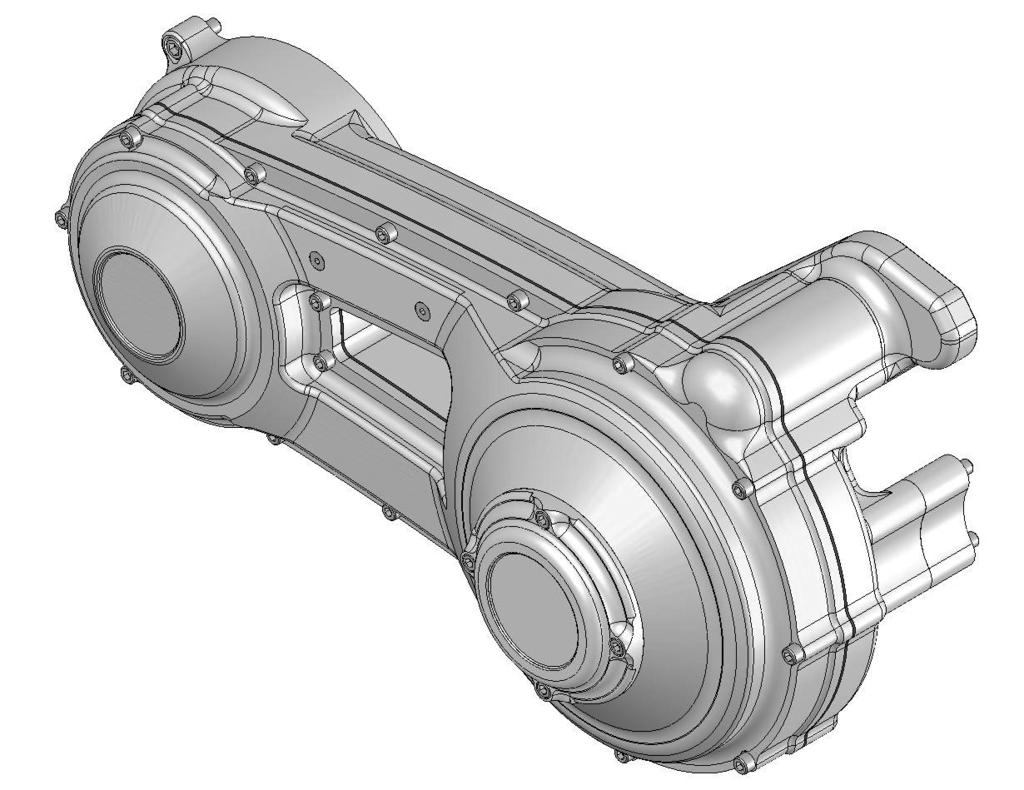
2 over view V FEATURES BAKER FUNCTION FORMED PRIMARY ALL BILLET 6061-T6 AIRCRAFT GRADE ALUMINUM CONSTRUCTION One piece STARTER jackshaft (INCLUDED) High torque inner primary bearing POLISHED Stainless steel fasteners externally ADJUSTABLE CHAIN TENSIONER WITH UPPER RUNG ACCESS COVER COMPATIBLE WITH ALL HARLEY SOFTAIL CLUTCHES, COMPENSATING SPROCKETS, STARTERS AND BAKER EQUIVALENT AVAILABLE IN SHOW PolishED or black anodized finish OPTIONAL UPGRADE TO KING KONG KLUTCH WITH INTERNAL BEARING SUPPORT PART NUMBERS AND APPLICATIONS: 4100P-FFP-E 4100B-FFP-E 4100P-FFP-L 4100B-FFP-L softail WITH 66 TOOTH CLUTCH RING GEAR, SHOW POLISHED SOFTAIL WITH 66 TOOTH CLUTCH RING GEAR, BLACK ANODIZED SOFTAIL WITH 102 TOOTH CLUTCH RING GEAR, SHOW POLISHED SOFTAIL WITH 102 TOOTH CLUTCH RING GEAR, BLACK ANODIZED PAGE 1 OVERVIEW
3 baker FUNCTION FORMED PRIMARY installation: table of contents: 1. Overview 2. Table of Contents 3. Included Parts Illustration 4. Included Parts Detail 5. Skills, Knowledge & Tools 6. Stock Bike Disassembly 7-9. Step by step installation 10. Terms 11. Disclaimer PAGE 2 TABLE OF CONTENTS


4 included parts PAGE 3 PARTS
5 included parts # Part Number Quantity Description FFp 1 Inner Primary FFp 1 Outer Primary FFp 1 Starter Ear Stand Off FFp 1 Rear Tranny Stand Off FFp 1 Front Tranny Stand Off FFp 1 Chain Adjustment Cover FFp 1 Clutch Adjustment Cover FFp 1 Chain Tensioner, Jack Male FFp 1 Chain Tensioner, Jack Female FFp 1 Upper Chain wear plate FFp 1 Lower Chain wear plate starter jack shaft 13 S starter jack shaft spring 14 S starter jack shaft washer /4-20x1/2 grade 8 flange bolt 16 56FFNNEOz 1 9/16-18 Lock nut K58 2 5/8 O.D. 1/16 C.S. (-014) K78 1 (-024) O-Ring A /4-20 x 3/8 Low Head Cap Screw A /4-20 x 3/4 Low Head Cap Screw 21 25C075KCSSP 10 1/4-20 x 3/4 SHCS 22 25C125KCSSP 3 1/4-20 x 1 1/4 SHCS 23 25C175KCSSP 5 1/4-20 x 1 3/4 SHCS /4 x 1/2 Dowel (Hardened Steel) A /16 x 2 1/2 Dowel (Hardened Steel) FFp 1 Outer Gasket FFp 1 Inner Gasket A /2 x.035 snap ring A x.062 snap ring B 1 jack shaft seal SFF 1 Mainshaft Bearing mainshaft seal Zero Leak Drain plug 34 PAPZ Perma glide bearing FFp 1 Chain Adj. shoe 36 31C225KCSOB 2 5/16-18 x 2 1/4 SHCS 37 31C200KCSOB 2 5/16-18 x 2 SHCS 38 31C100KCSOB 4 5/16-18 x 1 SHCS K132 1 (-043) O-ring,Clutch adjust cover A535 2 #10-24 SHCS x 3/ A /4-20 x 1/2 SHCS 42 37KKPD 1 3/8 Pipe Plug PAGE 4 PARTS

6 SKILLs, KNOWLEDGE & TOOls SKILL LEVEL: Installing the BAKER Function Formed Primary is straight forward with no special machining, welding or fabricating required. A healthy 1/2 impact gun with a 1-1/2 and 1-3/16 sockets and the special tool described below are adequate to get the job done. However, as with most things in life there are no substitutes for skill and experience. BAKER highly recommends that a Factory Service Manual and parts catalog specific to your model be available for reference. SPECIAL TOOLS: One special tool is required for the removal of the inner primary bearing race from the transmission mainshaft. Reference tool picture below. Inner Race Service Kit - from Baker - P/N: Tool B-56 or Harley Equivalent PAGE 5 skills, knowledge and tools

7 baker FUNCTION FORMED PRIMARY installation: STOCK BIKE DISSASSEMBLY: 1. For your safety, DISCONNECT BOTH BATTERY POSTS (FAILURE TO DUE SO COULD RESULT IN PERSONAL INJURY). 2. Remove primary drain plug located at the bottom of your primary, drain fluid and dispose of at your local recycler. 3. On some models it is necessary to remove foot pegs / floor boards in order to remove the outer primary. 4. Remove the stock outer primary cover. 5. Refer to your Factory Service Manual to remove your stock clutch assembly and related primary components using the proper safety precautions and tools. 6. Remove the stock inner primary housing per the Factory Service Manual. The left side of the transmission and engine should be visible as shown in Figure 1. Note: Figure 1 shows a 2005 Softail that has been converted to Right Side Drive, but the removal of the stock primary and installation of the Function Formed Primary is not affected by this. 7. Remove the inner primary bearing race from the mainshaft with BAKER Tool B-56 or the Harley equivalent. Follow the Factory Service Manual for this procedure. Figure 1 PAGE 6 assembly

 into the counter-bored hole. The snap ring serves as a secondary lock to ensure that a bolt does not back out.")
8 baker FUNCTION FORMED PRIMARY installation: INSTALLATION OF YOUR BAKER FUNCTION FORM PRIMARY: 1. Check the engine to primary O-ring, making sure it is free of debris and in good condition. Replace if needed. 2. Install the splined starter washer and the jackshaft spring. See Figures 2 and Install the inner primary with the included 5/16-18 SHCS included. Refer to exploded views for lengths. Apply a small amount of Red thread lock to the end of the threads on each of the 8 fasteners. Figure 2 4. Torque each of the fasteners to 220 IN/ LBS. On the 6 inner fasteners install a snap ring (supplied) into the counter-bored hole. The snap ring serves as a secondary lock to ensure that a bolt does not back out. (WARNING ALWAYS WEAR PROPER EYE PROTECTION WHEN REMOVING AND INSTALLING SNAP RINGS. SLIPPAGE MAY PROPEL THE SNAP RING INTO THE AIR). 5. Torque the two 5/16-18 starter bolts to their factory specs. 6. The one piece jack shaft now needs to be installed. Make sure the jackshaft spring and splined washer are still in place. Lubricate the jackshaft with bearing grease. Insert the shaft into the inner primary. 7. Apply Blue thread lock to the supplied 1/4-20x1/2 flange bolt and torque it to 120 IN/LBS. Figure 3 8. On versions, install the 3/8 pipe plug with blue thread locker. On versions, install the end plug with snap ring. PAGE 7 assembly


9 baker FUNCTION FORMED PRIMARY installation: 9. Slide the 5/16 diameter dowel into the chain adjuster shoe and then into the corresponding hole on the inner primary. See Figure Install your clutch assembly, primary chain, and motor sprocket components following the Factory Service Manual. See Figure Install compensating sprocket nut and clutch nut, using Red thread lock. 12. Torque to Factory specifications found in your Factory Service Manual. Figure Adjust primary chain following steps listed in your Factory Service Manual. 14. Install the Adjuster Plate and snap ring. Adjust the clutch following steps listed in your Factory Service Manual. 15. Install outer primary with supplied gaskets and 1/4-20 fasteners using a cross pattern. Starting with the 4 center Glory Hole fasteners, torque fasteners in the cross pattern to 110 IN/LBS. See Figure 6. Figure 5 Figure 6 PAGE 8 assembly

 19.")
10 baker FUNCTION FORMED PRIMARY installation: 16. Fill primary with 10oz-12oz of oil through the clutch adjustment cover opening. Fluid recommendation can be found in your Factory Service Manual or from your aftermarket clutch manufacturer. 17.Install the chain adjustment cover with the supplied #10-24 fasteners. Check that the O- ring is in place and free of debris. Be sure to use Blue thread lock on the fasteners. See Figure Install the clutch adjustment cover with the proper fasteners. See exploded diagram in front of Installation Instructions for details. Torque to 110 IN/LBS. See Figure 8. Figure 7 (MAKE SURE O-RING AND O-RING BORE ARE CLEAN AND FREE OF DEBRIS.) 19. If floor boards or pegs were removed to install your BAKER FFP reinstall them as per Factory Service Manual. FOR THE LIFE OF YOUR NEW BAKER FUNCTION FORM PRIMARY ALWAYS RE-ADJUST THE CHAIN TENSION TO THE FACTORY SERVICE MANUAL SPECIFICATIONS. THIS CAN VERY DEPENDING ON YOUR RIDING STYLE AND MAY BE REQUIRED MORE FREQUENTLY. Figure 8 PAGE 9 ASSEMBLY
11 terms SPECIAL ORDERS A minimum $500 deposit is required with all special orders. Special orders include unique case finishes, unique side door requests (i.e.; wrinkle black door or no logo). ALL OTHER ORDERS Orders can be pre-paid using VISA, Mastercard or American Express. Prices shown are F.O.B. Haslett, MI. BAKER TM provides free UPS ground shipping on all retail orders for complete transmissions or transmission kit. UPS air shipment is available upon request. Customer is responsible for air shipment premiums. LIMITED WARRANTY BAKER TM Inc. transmission assemblies, transmission kits, primaries, belt drives and wide tire kits are guaranteed to the original purchaser to be free of manufacturing defects in materials and workmanship for a period of 5 years from the date of purchase or up to 50,000 miles - whichever is sooner. If the product is found by BAKER TM to be defective, such products will, at the option of BAKER TM, be replaced or repaired at cost to BAKER TM. In the event warranty service is required, the original purchaser must call or write BAKER TM immediately with the problem. If it is deemed necessary for BAKER TM to make an evaluation to determine whether the transmission assembly or transmission kit is defective, the entire transmission assembly, whether originally purchased as an assembly or kit, must be properly packaged and returned prepaid to BAKER TM with a copy of the original invoice of purchase. If after an evaluation has been made by BAKER TM and a defect in materials and/or workmanship is found, BAKER TM will, at BAKER s option, repair or replace the defective part of the assembly. Warranty card must be returned within 45 days of purchase to be valid. ADDITIONAL WARRANTY PROVISIONS This limited warranty does not cover labor or other costs or expenses incidental to the repair and or replacement of BAKER TM products. This warranty does not apply if one or more of the following situations is judged by BAKER TM to be relevant: improper installation, accident, modification (including but not limited to use of unauthorized parts), racing, high performance application, mishandling, misapplication, neglect (including but not limited to improper maintenance), or improper repair. BAKER TM shall not be liable for any consequential or incidental damages arising out of or in connection with a BAKER TM transmission assembly, transmission kit, swingarm, fender, component or part. Consequential damages shall include without limitation, loss of use, income or profit, or losses sustained as the result of injury (including death) to any person or loss of or damage to property. BAKER TM transmissions, transmission kits, primaries, belt drives, and Wide Tire Kits are designed exclusively for use in Harley-Davidson motorcycles. BAKER TM shall have no warranty or liability obligation if a BAKER TM part is used in any other application. If it is determined that a BAKER TM transmission assembly has been disassembled during the warranty period for any reason, this limited warranty will no longer apply. PAGE 10 TERMS
12 discl aimer The words Harley, and H-D are registered trademarks and are for reference only. Use of H-D model designations and part numbers are for reference only. BAKER Drivetrain has no association with, and makes no claim against, these words, trademarks, or companies. It is the sole responsibility of the user to determine the suitability of this product for his or her use, and the user shall assume all legal, personal injury risk and liability and all other as well as all other obligations, duties and risks associated therewith. customer support For any installation or service questions, please contact our BAKER technical department toll free: Baker Drivetrain 9804 E. Saginaw Haslett, MI On the web: PAGE 11 DISCLAIMER
baker+1 oil Pan installation
 Installation Instructions over view baker+1 oil Pan installation V.2-29-08 FEATURES: 2 piece Billet Aircraft Grade 6061-T6 Aluminum Reduces engine oil temperature by 10 degrees on an 80 degree day. Multiple
KING KONG CLUTCH INSTALLATION INSTRUCTIONS
 KING KONG CLUTCH INSTALLATION INSTRUCTIONS over view BAKER KING KONG CLUTCH V.05_091008 FEATURES: 1 Piece steel clutch basket design 66 tooth ring gear configuration, 23% thicker than stock 20 massive
BAKER 9 PLATE AND BIG DOG CLUTCH PACK SERVICE KIT
 BAKER 9 PLATE AND BIG DOG CLUTCH PACK SERVICE KIT PAGE 1 BAKER 9 PLATE AND BIG DOG CLUTCH PACK SERVICE KIT TABLE OF CONTENTS: 1. Cover 2. Table of Contents 3. Exploded view 9plate 4. Exploded view BDM
BAKER ATTITUDE CHAIN ADJUSTER
 PN 177-67K INSTALLATION INSTRUCTIONS FEATURES TAG PN QTY DESCRIPTION 1 13061 2 5/16-18 X 2, Hex Bolt, Zinc 2 6100 2 5/16 ID AN Washers, SS 3 25CNTE8Y 1 1/4-20 Low Head Nylock Nut 4 178-67 1 Support Plate,
BAKER 9 PLATE AND BIG DOG CLUTCH PACK SERVICE KIT
 BAKER 9 PLATE AND BIG DOG CLUTCH PACK SERVICE KIT P/N: CPRK-9P CPRK-BDM (9 PLATE CLUTCH SERVICE PACK) (BIG DOG CLUTCH SERVICE PACK) PAGE 1 TABLE OF CONTENTS 1. Cover 2. Table of Contents 3. Exploded View
INSTALLATION INSTRUCTIONS
 INSTALLATION INSTRUCTIONS v.102306 BAKER COMPENSATING SPROCKET for 1985-2006 h-d FLT & FXR P/N 155-56S P/N 156-56S P/N 157-56S for 1985-2006 H-D SOFTAIL & DYNA P/N 155-56L P/N 156-56L P/N 157-56L BAKER
Function Formed FL Oil Spout
 Installation Instructions Function Formed FL Oil Spout over view Function Formed FL Oil Spout v.102516 FEATURES: The new line of BAKER FL Oil Spouts follows on the heels of other BAKER Function Formed
BAKER CRUISE DRIVE TOP COVER BAKER 1.5 OIL PAN
 BAKER BAKER CRUISE 1.5 DRIVE OIL TOP PAN COVER PN: BD-1.5B Wrinkle Black Highlighted Pan Assembly BD-1.5CVO Granite Highlighted Pan Assembly CVO Models BD-1.5P Show Polished Pan Assembly BD-1.5C Chrome
V PN 4-155N1-K (N1 Shift Drum Kit For Ratchet Style Top Covers) PAGE 1 COVER
 PAGE 1 COVER") BAKER 4-SPEED CRUISE N1 DRIVE SHIFT TOP DRUM COVER KIT V3-05222014 PN 4-155N1-K (N1 Shift Drum Kit For Ratchet Style Top Covers) PAGE 1 COVER FEATURES Tired of stalling your jockey shift bike while trying
BAKER 4-SPEED CRUISE N1 DRIVE SHIFT TOP DRUM COVER KIT V3-05222014 PN 4-155N1-K (N1 Shift Drum Kit For Ratchet Style Top Covers) PAGE 1 COVER FEATURES Tired of stalling your jockey shift bike while trying
baker drivetrain speedometer recalibration unit instructions
 baker drivetrain 2007-2009 speedometer recalibration unit instructions baker drivetrain - www.bakerdrivetrain.com - 1-877-640-2004 table of contents: 2) Table of Contents 3-4) Wiring Diagrams 5) Recalibration
OVERVIEW FEATURES APPLICATION AND REQUIRED HARDWARE
 PV0-908 OVERVIEW TM FEATURES The BAKER DD6 Transmission Builder s Kit comes with all of the necessary components to convert your stock 5-Speed into a 6-Speed, providing smoother shifting, positive neutral-finding,
Factory 5 Speed Kicker kit
 Factory 5 Speed Kicker kit 578-56MP-K Shown V4.010416 FEATURES 6061-T6 Aluminum billet bearing boor in show polish, raw finish, black finish 6061-T6 Aluminum billet side cover in show polish finish Clutch
PV BAKER HYDRAULIC SIDE COVERS FOR FACTORY 6-SPEED INSTALLATION INSTRUCTIONS
 BAKER HYDRAULIC SIDE COVERS FOR FACTORY 6-SPEED INSTALLATION INSTRUCTIONS BAKER HYDRAULIC SIDE COVERS FOR FACTORY 6-SPEED TABLE OF CONTENTS 1. CD6 Hydraulic Side Cover Detail View 2. M8 Hydraulic Side
BAKER CRUISE DRIVE TOP COVER BAKER 4 SPEED TRANSMISSION
 BAKER CRUISE 4 SPEED DRIVE TRANSMISSION TOP COVER P/N: 4-7085 (4 Speed Transmission; 1970-1985 Tapered Mainshaft) 4-70E84 (4 Speed Transmission; 1970-E1984 Splined Mainshaft) 4-6569 (4 Speed Transmission;
BAKER CRUISE DRIVE TOP COVER BAKER 4 SPEED TRANSMISSION P/N:
 BAKER CRUISE 4 SPEED DRIVE TRANSMISSION TOP COVER P/N: 4-7090 (4 Speed Transmission; 1970-E1984 Splined Mainshaft) 4-70E84 (4 Speed Transmission; 1970-E1984 Tapered Mainshaft) 4-6569 (4 Speed Transmission;
BAKER DD7 INSTALLATION INSTRUCTIONS
 BAKER DD7 INSTALLATION INSTRUCTIONS PAGE 1 OVERVIEW OVERVIEW FEATURES The all new BAKER DD7 is more than just another gear added to the mix for the sake of one-upmanship. That 7th gear enables the motorcycle
BAKER DD7 INSTALLATION INSTRUCTIONS
 BAKER DD7 INSTALLATION INSTRUCTIONS v.13-032917 PAGE 1 OVERVIEW OVERVIEW v.13-032917 FEATURES The all new BAKER DD7 is more than just another gear added to the mix for the sake of one-upmanship. That 7th
S&S. Cycle, Inc. Installation Instructions: Cam Support Plate for 2017-up M8 Models. Instruction
 Instruction 0-0 0-0- Version 0 by S&S Cycle, Inc. All rights reserved. Printed in the U.S.A. S&S Cycle, Inc. 0 Cty Hwy G Viola, Wisconsin Phone: 0-- Fax: 0-- Technical Service Phone: 0--TECH () Technical
BAKER FRANKENTRANNY BUILDER S KIT
 BAKER FRANKENTRANNY BUILDER S KIT BAKER Drivetrain s 1999 Road King w/part Numbers: FT106SL (Frankentranny Kit), 478-56CP-U84 (Kicker Cover), 3511-64 (Kick Arm/Pedal Assembly, 475-56P (Oil Spout Assembly),
Right Side Drive Builder s Kits
 INSTALLATION INSTRUCTIONS FOR Right Side Drive Builder s Kits Ground-up Construction Only Big Twin Applications 9804 E. Saginaw Haslett, MI. 48840 - Phone: (517) 339-3835 - Fax: (517) 339-4590 - Toll Free:
V (LSD Transmission with Hydraulic Clutch) (LSD R-Ratio Transmission with Hydraulic Clutch) P/N: PBL701PN PBL7211PN PAGE 1 COVER
 (LSD R-Ratio Transmission with Hydraulic Clutch) P/N: PBL701PN PBL7211PN PAGE 1 COVER") BAKER BAKER LEFT CRUISE SIDE DRIVE DRIVE (LSD) TOP POWERBOX COVER P/N: PBL701PN PBL7211PN (LSD Transmission with Hydraulic Clutch) (LSD R-Ratio Transmission with Hydraulic Clutch) PAGE 1 COVER BAKER LSD
BAKER BAKER LEFT CRUISE SIDE DRIVE DRIVE (LSD) TOP POWERBOX COVER P/N: PBL701PN PBL7211PN (LSD Transmission with Hydraulic Clutch) (LSD R-Ratio Transmission with Hydraulic Clutch) PAGE 1 COVER BAKER LSD
S&S. Installation Instructions for S&S Single Bore Tuned Induction Kit for 2008-Up Touring Models with Electronic Throttle Control
 Instruction 106-4891 06-24-14 Copyright 2009, 2014 by S&S Cycle, Inc. All rights reserved. Printed in the U.S.A. S&S Cycle, Inc. 14025 County Highway G PO Box 215 Viola, Wisconsin 54664 Phone: 608-627-1497
S&S. S&S Oil Supply Line Installation Kit PN (For Harley-Davidson Dyna Models) PN (For FLT Models)
 PN (For FLT Models)") Instruction 510-0039 03-07-13 Copyright 2011, 2013 by S&S Cycle, Inc. All rights reserved. Printed in the U.S.A. S&S Cycle, Inc. 14025 County Highway G PO Box 215 Viola, Wisconsin 54664 Phone: 608-627-1497
Instruction 510-0039 03-07-13 Copyright 2011, 2013 by S&S Cycle, Inc. All rights reserved. Printed in the U.S.A. S&S Cycle, Inc. 14025 County Highway G PO Box 215 Viola, Wisconsin 54664 Phone: 608-627-1497
S&S. Installation Instructions: S&S Stealth Air Cleaner Covers. Instruction IMPORTANT NOTICE:
 Instruction 510-0226 09-03-13 Copyright 2013 by S&S Cycle, Inc. All rights reserved. Printed in the U.S.A. S&S Cycle, Inc. 14025 Cty Hwy G PO Box 215 Viola, Wisconsin 54664 Phone: 608-627-1497 Fax: 608-627-1488
BAKER FACTORY 5 SPEED REVERSE
 INSTALLATION INSTRUCTIONS FITMENT & OPTIONS PN F5-RV-1 PN F5-RV-2 PN F5-RV-3* 1990-1997, All Factory 5 Speed Models 1998-1999 Softail, 1998-2000 FLT, FLH & Dyna, 1999 FXR 2000-2006 Softail, 2001-2006 FLT,
ASSEMBLY DIAGRAM AND ASSEMBLY REFERENCE ULTIMA OLD SCHOOL 2 BELT DRIVE UNITS
 ASSEMBLY DIAGRAM AND ASSEMBLY REFERENCE ULTIMA OLD SCHOOL 2 BELT DRIVE UNITS BELT DRIVE ASSEMBLIES Part# 58-850 2 Old School Belt Drive Assembly - Polished Part# 58-851 2 Old School Belt Drive Assembly
S&S. Installation Instructions for S&S VFI Knock Sensor Kit for 2001-'07 Delphi Style VFI Module (with USB) Instruction
 Instruction") Instruction 106-1544 9-28-07 Copyright 2007 by S&S Cycle, Inc. All rights reserved. Printed in the U.S.A. S&S Cycle, Inc. 235 Causeway Blvd. La Crosse, Wisconsin 54603 Phone: 608-627-1497 Fax: 608-627-1488
Instruction 106-1544 9-28-07 Copyright 2007 by S&S Cycle, Inc. All rights reserved. Printed in the U.S.A. S&S Cycle, Inc. 235 Causeway Blvd. La Crosse, Wisconsin 54603 Phone: 608-627-1497 Fax: 608-627-1488
Cycle, Inc. S&S. Installation Instructions: Chain Drive Camshaft for 2017 Harley-Davidson Milwaukee Eight Engines. Instruction
 Instruction 0-067 0-8-07 Version Copyright 07 by S&S Cycle, Inc. All rights reserved. Printed in the U.S.A. S&S Cycle, Inc. 0 Cty Hwy G Viola, Wisconsin 66 Phone: 608-67-97 Fax: 608-67-88 Technical Service
S&S. Instruction Copyright 2014, Version 4 by S&S Cycle, Inc.
 Instruction 510-0295 10-02-2017 Copyright 2014, 2016. 2017 Version 4 by S&S Cycle, Inc. All rights reserved. Printed in the U.S.A. S&S Cycle, Inc. 14025 Cty Hwy G PO Box 215 Viola, Wisconsin 54664 Phone:
HOME OF PRIMO BELT DRIVES QUALITY & PERFORMANCE SINCE 1973 BRUTE FORCE TM. Belt Drive INSTALLATION INSTRUCTIONS
 HOME OF PRIMO BELT DRIVES QUALITY & PERFORMANCE SINCE 1973 BRUTE FORCE TM Belt Drive INSTALLATION INSTRUCTIONS 3-1/2 WIDE / 14mm BELT FITS 1990-2006 EVO & TWIN CAM SOFTAIL PRIMO BRUTE FORCE TM BELT DRIVE
DYNA EVO & T.C. MODELS 91-05
 ASSEMBLY DIAGRAM AND ASSEMBLY REFERENCE ULTIMA OLD SCHOOL 2 BELT DRIVE UNITS DYNA EVO & T.C. MODELS 91-05 Part # 58-900 2 BELT DRIVE ASSEMBLY REV 1-20-10 ASSEMBLY DIAGRAM AND ASSEMBLY REFERENCE ULTIMA
SLAB SAW SERIES PARTS LIST
 SLAB SAW SERIES PARTS LIST MODELS: HP Part# 020 HP20 Part# 02020 HP2 Part# 0202 MADE IN USA MADE IN USA Revision 09.20 Manual Part No. 6269 Caution: Read all safety and operating instructions before using
INSTALLATION BLIND SPOT TURN SIGNAL MIRRORS 1457
 BLIND SPOT TURN SIGNAL MIRRORS 1457 PARTS INCLUDED 2 Blind Spot Turn Signal Mirror Assemblies 1 Wire Harness Kit Including: 2 Wiring Harness (four pin) 1 Adapter Harness (six pin) 2 3-Pin Female Connectors
Contour Floor Boards For 1991 through 2007 Big Twins
 Installation Instructions Contour Floor Boards For 1991 through 2007 Big Twins ATTENTION Statements in these instructions that are preceded by the following words are of special significance: W a r n i
HP30 Slab Saw Owner s Manual and Operating Instructions
 HP30 Slab Saw Owner s Manual and Operating Instructions MADE IN USA Revision 07 09.0 Manual Part No. 67 Caution: Read all safety and operating instructions before using this equipment. This manual MUST
DYNA EVO & T.C. MODELS 91-05
 ASSEMBLY DIAGRAM AND ASSEMBLY REFERENCE ULTIMA OLD SCHOOL 2 BELT DRIVE UNITS DYNA EVO & T.C. MODELS 91-05 Part # 58-900 2 BELT DRIVE ASSEMBLY REV 10-22-14 ASSEMBLY DIAGRAM AND ASSEMBLY REFERENCE ULTIMA
S&S. Instruction IMPORTANT NOTICE:
 Instruction 106-4426 10-31-08 Copyright 2008 by S&S Cycle, Inc. All rights reserved. Printed in the U.S.A. S&S Cycle, Inc. 235 Causeway Blvd. La Crosse, Wisconsin 54603 Phone: 608-627-1497 Fax: 608-627-1488
left-side-drive hydraulic side cover installation manual
 left-side-drive hydraulic side cover installation manual rear feed and front feed models rear feed front feed for baker OD6, dd5, dd6, and stock H-D 5-speeds v3-021307 DD5, DD6, and Stock H-D Instructions
AT Clutch Major Service Sizes 25, 55, 115
 P-1404 819-0324 AT Clutch Major Service Sizes 25, 55, 115 Installation Instructions Contents Introduction............................ 2 Warranty....................... back cover Failure to follow these
S&S. Installation Instructions: S&S Billet Air Cleaner Kit PN for Victory Motorcycles. Instruction IMPORTANT NOTICE:
 Instruction 106-1330 06-23-10 Copyright 2008, 2009, & 2010 by S&S Cycle, Inc. All rights reserved. Printed in the U.S.A. S&S Cycle, Inc. 14025 Cty Hwy G PO Box 215 Viola, Wisconsin 54664 Phone: 608-627-1497
READ ALL INSTRUCTIONS BEFORE PERFORMING WORK! IF YOU DO NOT KNOW WHAT YOU ARE DOING, DO NOT DO IT!
 Instructions for the following part no s: 8280, 8279, 8282, 8283, 8284, 8273, 8274, 8275 These instructions are for installation of both Super Kit or complete transmission, for EVO or Twin Cam. These instructions
900 SERIES SPLIT CASE FIRE PUMP REPAIR PARTS INDEX
 900 SERIES SPLIT CASE FIRE PUMP REPAIR PARTS INDEX Read and understand the pump and motor instructions before attempting to install, disassemble or repair the pump. Part # AF-03-326 2015 Pentair Ltd. 01/30/15
PARTS CATALOG FOR. Mud Hog Rear Wheel Drive FOR. MF 9540/9550/9560, CAT 540C/550C/560C, Gleaner A540/A560, Fendt 6450R/9480R COMBINES
 PARTS CATALOG FOR Mud Hog Rear Wheel Drive FOR MF 9540/9550/9560, CAT 540C/550C/560C, Gleaner A540/A560, Fendt 6450R/9480R COMBINES Mud Hog Model Number: AG9896 A Product of Tuthill Drive Systems P.O.
INSTALLATION INSTRUCTIONS
 MINIMUM REQUIRED TOOLS: INSTALLATION INSTRUCTIONS PRO DUALS TOURING FLAT HEAD SCREWDRIVER 1/2, 9/16, 14mm, 7/8 or 22mm WRENCHES 5/16, 1/2, 9/16 SOCKETS AND RATCHET SNAP RING PILERS 3/16, 1/4, 5/16 ALLEN
S&S Cycle, Inc County Hwy. G Box 215 Viola, Wisconsin U.S.A.
 Instruction Sheet 51-1046 1-28-03 Copyright 1999, 2003 by S&S Cycle, Inc. All rights reserved. Printed in the U.S.A. S&S Cycle, Inc. 14025 County Hwy. G Box 215 Viola, Wisconsin 54664 U.S.A. Phone 608-627-2080
AEROMOTIVE Part # A2000 Fuel Pump Kit INSTALLATION INSTRUCTIONS
 AEROMOTIVE Part # 17202 A2000 Fuel Pump Kit INSTALLATION INSTRUCTIONS CAUTION: Installation of this product requires detailed knowledge of automotive systems and repair procedures. We recommend that this
From The Track... To The Street!
 Instruction Sheet For JIMS Twin Cam Flywheel Assemblies & Big Bore Kit For the following part numbers 1881, 1882, 1883, 1884, 1886, 1888, 1937, 1938, 1941, 1942, 1943, 1944, 1945, 1946, 1957, 1958, 1959,
JOHN DEERE 9970 COTTON PICKERS
 PARTS CATALOG FOR Mud Hog System II Rear Wheel Drive FOR JOHN DEERE 9970 COTTON PICKERS Mud Hog Model Numbers Tread Center OEM Aftermarket JD40005 JD47655 82, 90, 94, 106 TUTHILL Drive Systems 9098 West
Stellar 4 Clutch Manual
 INSTRUCTIONS Stellar 4 Clutch Manual Thank you for choosing Tomar products; we are proud to be your manufacturer of choice. Please read this instruction sheet carefully before beginning installation, and
INSTALLATION FORK MOUNTED DRIVING LIGHTS 5008
 5008 PARTS INCLUDED 1 Right Fork Mount Assembly 1 Left Fork Mount Assembly 2 H3 Driving Light Assemblies 1 12-Pin Wiring Adapter 1 Hardware Kit for Fork Mount Driving Lights, Including: 6 5/16-18 Nylock
AEROMOTIVE Part # Fuel System Prime Kit INSTALLATION INSTRUCTIONS
 AEROMOTIVE Part # 17301 Fuel System Prime Kit INSTALLATION INSTRUCTIONS CAUTION: Installation of this product requires detailed knowledge of automotive systems and repair procedures. We recommend that
BULLETIN 2212 P Installation Instructions. thru 1027
 BULLETIN 2212 P-222-5 Installation Instructions HPO Outer Race Overrunning Clutches Models HPO 720 thru 1027 The HPO model high performance overrunning clutches are especially designed for high speed,
Installation Instructions Compressor Kit Harley Davidson Dyna Glide Important Notice
 Installation Instructions Compressor Kit Harley Davidson Dyna Glide 91-07 ATTENTION Statements in these instructions that are preceded by the following words are of special significance: W a r n i n g
GEN-3 Super-duty Supercharger Shaft Kit PART# - RY17040-UK-6S5-3
 GEN-3 Super-duty Supercharger Shaft Kit PART# - RY17040-UK-6S5-3 We strongly recommend the use of a service manual to familiarize yourself with the various components and procedures involved with this
JK CARGO STORAGE RACK
 1 JK CARGO STORAGE RACK #4820020 Important Notes: Prior to beginning this or any installation read these instructions to familiarize yourself with the required steps and evaluate if you are experienced
Special Purpose Overrunning Clutches ep 300 thru 1027 (less Oil Seals)
") Special Purpose Overrunning Clutches ep 300 thru 1027 (less Oil Seals) P-222-30 Bulletin 4701 Service & Installation Instructions introduction EP models are special purpose ball bearing clutches suitable
Special Purpose Overrunning Clutches ep 300 thru 1027 (less Oil Seals) P-222-30 Bulletin 4701 Service & Installation Instructions introduction EP models are special purpose ball bearing clutches suitable
CRUSHER MAVERICK 2 INTO 2, BLACK 566
 CRUSHER MAVERICK 2 INTO 2, BLACK 566 THANK YOU FOR CHOOSING CRUSHER! PROTECT YOURSELF AND OTHERS FROM POTENTIAL INJURY AND PROPERTY DAMAGE OR LOSS. PAY CLOSE ATTENTION TO ALL INSTRUCTIONS, WARNINGS, CAUTIONS,
231 SYE Heavy Duty Short Shaft Kit
 1 231 SYE Heavy Duty Short Shaft Kit www.teraflex.com Kit #4444401 Important Notes: Prior to beginning this or any installation read these instructions to familiarize yourself with the required steps and
S&S. Installation Instructions for S&S Sealed Air Cleaner. Instruction IMPORTANT NOTICE:
 Instruction 106-2707 11-20-08 Copyright 2008 by S&S Cycle, Inc. All rights reserved. Printed in the U.S.A. S&S Cycle, Inc. 235 Causeway Blvd. La Crosse, Wisconsin 54603 Phone: 608-627-1497 Fax: 608-627-1488
Straight-Bore Clutch LSCC-32, 44, 54
 Straight-Bore Clutch LSCC-32, 44, 54 1 In accordance with Nexen s established policy of constant product improvement, the specifications contained in this manual are subject to change without notice. Technical
Slimline Duals Installation Instructions Harley-Davidson Touring Models 2009-Current
 Slimline Duals Installation Instructions Harley-Davidson Touring Models 2009-Current Thank you for buying a Rinehart Racing exhaust system. We are committed to providing premium products that with proper
AEROMOTIVE Part # and F-Body Fuel System Kit INSTALLATION INSTRUCTIONS
 AEROMOTIVE Part # 17101 and 17102 93-97 F-Body Fuel System Kit INSTALLATION INSTRUCTIONS CAUTION: Installation of this product requires detailed knowledge of automotive systems and repair procedures. We
Universal Bevel Drives Service Manual
 Engineering Service Bulletin #SB241202 Universal Bevel Drives Service Manual Cautions Following are some general cautions. All personnel shall use safe and sound practices and take all necessary precautionary
Harley Davidson FL Touring Current Xtreme
 ITEMS SUPPLIED Description Part # Qty Front Header (Chr/Blk) 100-0119/100-0123 1 Rear Header (Chr/Blk) 100-0120/100-0124 1 Front Heat Shield (Chr/Blk) 100-0121/100-0125 1 Rear Heat Shield (Chr/Blk) 100-0122/100-0126
Be sure to refer to instruction supplements provided in any included mounting hardware. Installation Instructions 412CRZ Series Rear Shocks
 Installation Instructions 412CRZ Series Rear Shocks ATTENTION Statements in these instructions that are preceded by the following words are of special significance: W a r n i n g This means there is the
POWER CELL FOR DYNA WITH CLEAN CHROME COVER 562
 POWER CELL FOR DYNA WITH CLEAN CHROME COVER 562 THANK YOU FOR CHOOSING CRUSHER! PROTECT YOURSELF AND OTHERS FROM POTENTIAL INJURY AND PROPERTY DAMAGE OR LOSS. PAY CLOSE ATTENTION TO ALL INSTRUCTIONS, WARNINGS,
INSTALLATION. DRIVING LIGHTS for FLHT/FLHX/FLHR 5005
 DRIVING LIGHTS for FLHT/FLHX/FLHR 5005 PARTS INCLUDED 1 Right Driving Light Assembly 1 Left Driving Light Assembly 1 Right Driving Light Bracket 1 Left Driving Light Bracket 4 Driving Light Bracket Plugs
BRUTE IV EXTREME TM BELT DRIVE FOR 1990 TO 2005 EVO & TWIN CAM Dyna Models
 INSTALLATION INSTRUCTIONS FOR BRUTE IV EXTREME TM BELT DRIVE FOR 1990 TO 2005 EVO & TWIN CAM Dyna Models PLEASE NOTE: PICTURES CONTAINED WITHIN THIS INSTRUCTION SHEET ARE ALSO USED FOR OTHER INSTRUCTIONS,
INSTALLATION INSTRUCTIONS FOR BRUTE IV EXTREME TM BELT DRIVE
 INSTALLATION INSTRUCTIONS FOR BRUTE IV EXTREME TM BELT DRIVE FOR 1990 TO PRESENT EVO & TWIN CAM SOFTAILS Shown w/optional mid-shift control It s common knowledge that a belt drive primary can provide advantages
JK HD Skid Plate for Rear Falcon Shocks
 1 JK HD Skid Plate for Rear Falcon Shocks Kit # 36-07-01-300 Important Notes: Prior to beginning this or any installation read these instructions to familiarize yourself with the required steps and evaluate
AEROMOTIVE Part # & Generic Fuel System Kit INSTALLATION INSTRUCTIONS
 AEROMOTIVE Part # 17135 & 17136 Generic Fuel System Kit INSTALLATION INSTRUCTIONS CAUTION: Installation of this product requires detailed knowledge of automotive systems and repair procedures. We recommend
RACE PPE Manifolds and Up-Pipes
 RACE ONLY High-Flow Exhaust Manifolds with Up-pipes GM DURAMAX 6.6L 2001-2015 DISCLAIMER OF LIABILITY This is a performance product which increases horsepower above factory specifications. Additional horsepower
WARRANTY REGISTRATION FORM
 WARRANTY REGISTRATION FORM Please read & fill out attached warranty registration form to activate warranty This warranty registration must be received within 45 days from the time of purchase. Your New
INSTALLATION MANUAL. TORQ Locker TL GM 14 Bolt Installation Instructions. Made in USA By: Page 1 of 8
 INSTALLATION MANUAL TORQ Locker TL-19035 GM 14 Bolt Installation Instructions Made in USA By: Page 1 of 8 Page 2 of 8 INSTALLATION MANUAL TORQ Locker TL-19035 GM 14 Bolt Installation Instructions By: INTRODUCTION
Extreme Short Shaft Kit Part #
 TeraFlex, Inc. 5241 South Commerce Dr. Murray, Utah 84107 Phone/801.288.2585 Fax/801.713.2313 www.teraflex.biz Rev. 24 January 2011 TT PRODUCT INSTALLATION GUIDE Important Notes: Extreme Short Shaft Kit
Installation. Installation Instructions Monotube Cartridge Fork Kit 97-Later* Harley Davidson FLH/FLT
 Installation Instructions Monotube Cartridge Fork Kit 97-Later* Harley Davidson FLH/FLT ATTENTION Statements in these instructions that are preceded by the following words are of special significance:
V-Twin Forward Control Installation Instructions
 V-Twin Forward Control Installation Instructions Thank you for a choosing a Supreme Legends USA product. Supreme Legends forward controls are designed to add style and performance to your bike. Our extended
INSTRUCTIONS SOFTAIL 6 SPEED TRANSMISSION - COMPLETE 1WARNING -J03479 REV General. Removal of Original Transmission
 INSTRUCTIONS REV. 10-13-2005 Kit Numbers 330-03A, 33045-03A General SOFTAIL 6 SPEED TRANSMISSION - COMPLETE These kits fit 2000 and later carbureted and 2001 and later EFI Softail model motorcycles. Requires
JL Adjustable Spare Tire Mounting Kit
 1 JL Adjustable Spare Tire Mounting Kit # 4838910 Important Notes: Prior to beginning this install, or any installation, read the instructions thoroughly to familiarize yourself with the required steps.
416 Air Shocks For Harley Davidson FLH/FLT 97-later*.
 Installation Instructions ATTENTION Statements in these instructions that are preceded by the following words are of special significance: W a r n i n g This means there is the possibility of injury to
Through-Shaft Clutch-Brake LSCB-32HT, LSCB-32HT, LSCB-44, LSCB-44HT, LSCB-54HT FORM NO. L D-0606 MEX (55) QRO (442)
 QRO (442)") Through-Shaft Clutch-Brake LSCB-HT, LSCB-HT, LSCB-, LSCB-HT, LSCB-5HT In accordance with Nexen s established policy of constant product improvement, the specifications contained in this manual are subject
Through-Shaft Clutch-Brake LSCB-HT, LSCB-HT, LSCB-, LSCB-HT, LSCB-5HT In accordance with Nexen s established policy of constant product improvement, the specifications contained in this manual are subject
A Division of Thiessen Products, Inc.
 Instructions for the following part no s: 8280, 8279, 8282, 8283, 8284, 8273, 8274, 8275, & 8277 These instructions are for installation of the Super Kit, complete transmission, or rebuild kit for EVO
AEROMOTIVE Part # Subaru Fuel Rails for Top Feed Injectors WRX & STI INSTALLATION INSTRUCTIONS
 AEROMOTIVE Part # 14135 Subaru Fuel Rails for Top Feed Injectors 02-14 WRX & 07-14 STI INSTALLATION INSTRUCTIONS CAUTION: Installation of this product requires detailed knowledge of automotive systems
ACF Operation Manual
 ACF-3000 Operation Manual MAHLE Aftermarket Inc., RTI Division 10 Innovation Drive York, Pennsylvania 17402 USA Phone: 717-840-0678 Toll Free: 800-468-2321 Web-site: www.rtitech.com Manual P/N: 035 81825
DeZURIK 2 20" BOS BUTTERFLY VALVES
 2 20" BOS BUTTERFLY VALVES Instruction D10459 October 2013 2-20 BOS Butterfly Valves Instructions These instructions provide information about BOS Butterfly Valves. They are for use by personnel who are
Advanced Technology Tension Clutches
 P-220 819-0339 Advanced Technology Tension Clutches Installation Instructions Contents Installation................................. 2 Clutch Repair On the Shaft.................. 4 Clutch Service Major.......................
HP14 Slab Saw Owner's Manual and Operating Instructions
 Slab Saw Owner's Manual and Operating Instructions MADE IN USA Revision 112 09.2018 Manual Part No. 1771 Caution: Read all safety and operating instructions before using this equipment. This manual MUST
AEROMOTIVE Part # Generic Fuel System Kit INSTALLATION INSTRUCTIONS
 AEROMOTIVE Part # 17126 Generic Fuel System Kit INSTALLATION INSTRUCTIONS CAUTION: Installation of this product requires detailed knowledge of automotive systems and repair procedures. We recommend that
AEROMOTIVE Part # Mustang 5.0L Fuel System Kit INSTALLATION INSTRUCTIONS
 AEROMOTIVE Part # 17103 83-93 Mustang 5.0L Fuel System Kit INSTALLATION INSTRUCTIONS CAUTION: Installation of this product requires detailed knowledge of automotive systems and repair procedures. We recommend
INSTALLATION INSTRUCTIONS
 PERFORMER 2 INTO 1 TOURING MINIMUM REQUIRED TOOLS: INSTALLATION INSTRUCTIONS FLAT HEAD SCREWDRIVER 1/2, 9/16, 14mm, 7/8 or 22mm WRENCHES 5/16, 1/2, 9/16 SOCKETS AND RATCHET SNAP RING PILERS 3/16, 1/4,
Waukesha ISR FPO INSTRUCTION MANUAL INTEGRAL SPEED REDUCER SERIES
 INSTRUCTION MANUAL Waukesha ISR INTEGRAL SPEED REDUCER SERIES FORM NO.: REVISION: 08/1997 READ AND UNDERSTAND THIS MANUAL PRIOR TO OPERATING OR SERVICING THIS PRODUCT. FPO 2 SAFETY Warnings, cautions and
Rzeppa Factory Replacement CV Joint
 1 Rzeppa Factory Replacement CV Joint #1744014 JK Rzeppa CV Factory Replacement Kit Important Notes: Prior to beginning this or any installation read these instructions to familiarize yourself with the
AEROMOTIVE Part # & Mustang 5.0L Stealth Fuel System Kit INSTALLATION INSTRUCTIONS
 AEROMOTIVE Part # 18653 & 18654 86-93 Mustang 5.0L Stealth Fuel System Kit INSTALLATION INSTRUCTIONS CAUTION: Installation of this product requires detailed knowledge of automotive systems and repair procedures.
Rzeppa Factory Replacement CV Joint
 1 Rzeppa Factory Replacement CV Joint www.teraflex.com #1744014 Important Notes: Prior to beginning this or any installation read these instructions to familiarize yourself with the required steps and
AEROMOTIVE Part # Street Rod Fuel Pump System INSTALLATION INSTRUCTIONS
 AEROMOTIVE Part # 17201 Street Rod Fuel Pump System INSTALLATION INSTRUCTIONS CAUTION: Installation of this product requires detailed knowledge of automotive systems and repair procedures. We recommend
AEROMOTIVE Part # Subaru STI Fuel Rail Kit INSTALLATION INSTRUCTIONS
 AEROMOTIVE Part # 14137 04-06 Subaru STI Fuel Rail Kit INSTALLATION INSTRUCTIONS CAUTION: Installation of this product requires detailed knowledge of automotive systems and repair procedures. We recommend
INSTRUCTIONS SCREAMIN EAGLE FLHT 6-SPEED TRANSMISSION 1WARNING -J03322 REV Installation. General. Prepare the Motorcycle for Service
 INSTRUCTIONS REV. 02-11-2005 Kit Number 33136-04 and 33137-04 SCREAMIN EAGLE FLHT 6-SPEED TRANSMISSION General The Screamin Eagle FLHT 6-Speed Transmission kit fits 2002 and later Harley-Davidson Touring
Installation Instructions
 85-3511 rev. 04 11-15 Installation Instructions Polyurethane Bushing Kit for Ford F-53 (Front) (replaces OE bushings and brackets) part #4139-127 1-5/8 diameter INTRODUCTION Thank you for purchasing this
INSTALLATION INSTRUCTIONS
 INSTALLATION INSTRUCTIONS RIOT DYNA MINIMUM REQUIRED TOOLS: FLAT HEAD SCREWDRIVER 1/2, 9/16, 14mm, 7/8 or 22mm WRENCHES 5/16, 1/2, 9/16 SOCKETS AND RATCHET SNAP RING PILERS 3/16, 1/4, 5/16 ALLEN WRENCH
INSTRUCTIONS. Triangulated 4-Link Coil Over Rear Suspension System (RS-2450) For FORD Muscle Cars: FAIRLANE
 For FORD Muscle Cars: FAIRLANE") FORD 1962-65 FAIRLANE 4-LINK TRIANGULATED SYSTEM INSTRUCTIONS Triangulated 4-Link Coil Over Rear Suspension System (RS-2450) For FORD Muscle Cars: 1962-1965 FAIRLANE Revised: 10-1-2011 1962-1965 Fairlane
FORD 1962-65 FAIRLANE 4-LINK TRIANGULATED SYSTEM INSTRUCTIONS Triangulated 4-Link Coil Over Rear Suspension System (RS-2450) For FORD Muscle Cars: 1962-1965 FAIRLANE Revised: 10-1-2011 1962-1965 Fairlane