OWER'S MANUAL. Corse
|
|
|
- Bernice Daniels
- 5 years ago
- Views:
Transcription
1 OWER'S MANUAL Corse
2 This manual must be considered as an integral part of your outboard motor and has to be kept with it, also if the motor is resold. Selva joint-stock CO. reserve the right to change its product at any moment, except for the essential specifications, which will be kept as they are. Any reference to products or details of a third party has only an informative purpose and it doesn't represent an obligation. Selva joint-stock CO. doesn't take on any responsibility concerning the performance or the employment of these products. We are glad that you have chosen a SELVA MARINE product, which means quality, technology and careful research. Your choice will give you many advantages, which you will soon learn to appreciate. Our dealers, our after-sales service and the guarantee, which you have signed, together with the observance of the information contained in this owner's manual are the essential conditions to give your recent purchase a long life. Your holiday, your favorite sport, your job, which has from today the name SELVA MARINE, will be a further moment of satisfaction. This manual belongs to Selva joint-stock CO. All rights reserved. Any partial or total reprinting without the permission is prohibited. 1
3 INTRODUCTION Before operating this outboard motor, read this Owner's Manual carefully and completely, pay attention especially to the safety measures and rules. Your safety and other people's safety do not depend only on your ability at using the motor, but they depend also on your knowledge and on the efficiency of the motor as well as on the respect of the laws and regulations relating to the use of outboard motors. We suggest you improve your knowledge of the motor so that you can sail with mastery and confidence. If any kind of repair on the motor should not have been clearly described in this manual or if you want to order spare parts or accessories, or if you have any question about the operation or maintenance of your outboard motor, please consult an authorized SELVA MARINE service station or SELVA MARINE dealer ATTENTION Pay attention to all the particularly important information that in this manual are distinguished in the following ways: Safety measures and rules, which protect the machine operator and other people from serious accidents or risks. Directions or special precautions that must be taken to avoid damage to the outboard motor or personal accidents. Directions that make procedures easier or clearer. Technical information. 2
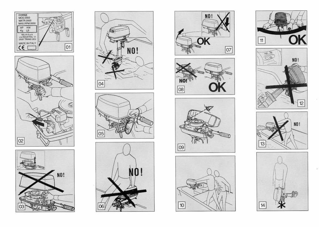
4 OUTBOARD MOTOR IDENTIFICATION DATA SERIAL NUMBER RECORD This data is stamped on the label attached on the clamp bracket, as shown on the picture 1. When you receive your new SELVA outboard motor write down the serial number, it will be useful to you in case you will have to order spare parts or for reference if your outboard motor should be stolen. Write down the identification number and the model of your outboard motor in the spaces below. MODEL Make sure that the data on the label is the same as the data written in your registration book. Picture No.1 SERIAL NUMBER Do not install an outboard motor with more horsepower than shown in the certification of your boat. 3
5 CONTENTS GENERAL INFORMATION...1 Introduction...2 Outboard motor identification data...3 Serial number record...3 Directions for use. Basic safety measures...5 Specifications...8 Location of main components...9 Control functions...10 Wiring diagram...11 Symbols...11 THE USE OF OUTBOARD MOTOR...12 Preliminary controls chart...12 Check of the supply...13 Outboard motor mounting...13 Trim angle adjusting...14 Fuel...15 Fuel...15 Preparation of the fuel...15 Starting...16 Verifications before starting the motor...16 Starting procedures...16 Verifications when the motor is on...16 Running-in procedure...16 Stopping procedure...17 Emergency stopping procedures...17 Stopping in normal conditions...17 Operating in reverse gear...17 Removal of the motor from the boat...17 Cleaning...18 Cleaning outside...18 Cleaning cooling-water passages...18 MAINTENANCE...18 Introduction...18 Periodic inspections and adjustments chart...19 Greasing chart...19 Greasing and additions...20 Gearbox-oil change...20 Spark-plug...20 Sacrificial anode...21 Replacement of the propeller...21 Storage...21 TROUBLESHOOTING...22 Troubleshooting chart...22 EXPLANATORY PICTURES
6 DIRECTIONS FOR USE BASIC SAFETY MEASURES To use the outboard motor you must have all requisites provided by law (physical suitability, insurance, government duties, registration, and so on). We suggest you become familiar with your boat equipped with SELVA motor in places, which are not too crowded. Taking some medicines, alcoholic drinks or drugs increase considerably the risk of accidents. Make sure that you are in a physical condition suitable for driving. Pay attention to tiredness and sleepiness. The engine operator should not let his mind wander, or be distracted or influenced by other people, things or actions,(do not smoke, eat, read, and so on.) while steering the boat. Use fuels and oils suitable for the engine, which are listed in the "greasing chart ". Check every so often the oil level and the fuel level. Stop the motor before every kind of maintenance or cleaning procedures, and in case of complicated maintenance take the spark-plug cap out. Picture No. 2. Before opening the top cowling, wait till the engine has cooled down. Do not open the top cowling, when the engine is running. Picture No. 3. 5
7 PAY ATTENTION TO THE PROPELLER The propeller is certainly the least protected part of your motor. It is therefore forbidden to get near the propeller when this is in rotating. You must leave bathers, skiers and other boat users enough space to move, in order to avoid any contact with the propeller. Picture No. 4. The engine operator must attach the engine stop switch lanyard to his wrist when the motor is on. Picture No. 5. Never sit on the motor. Picture No. 6. Never change the inclination angle of your motor using the steering rod, but use the proper handle. Picture No. 7. The motor must always have its top cowling on, when it is operating Picture-No. 8. When you connect the fuel joint, check the proper connection. Picture No. 9. There must be nobody within the motor steering radius. Picture No. 11. Never tilt-up the motor out of the water, while it is in motion. Picture No. 12. Never pull the recoil starter handle, while the motor is running. Picture No. 13. To transport the motor use only the proper handle. Before transporting the motor you have to tilt-up the steering rod properly and the event valve on the fuel tank must be closed. Picture No. 14. When starting or operating the engine, do not touch electrical parts and particularly the ignition-coil, the high voltage wire, the spark-plug cap and the spark-plug itself. When opening the safety valve of the fuel tank, highly flammable vapors come out. Do not smoke, inhale or use open flames close to it. When starting there must be nobody within the engine operator's action radius. Picture No
8 If the motor has had an accident, you should have it fully checked, before you use it again. If necessary let the SELVA MARINE authorized skilled staff have a look at it. Do not use the motor, if the damage could have compromised the sailing safety. Any alteration attempted on your motor or the removal of any of its basic elements, can compromise its safety and it is besides against the law, and anyway it means the immediate loss of your guarantee. Observe the laws in force. Prevent fires and explosions. Before operating an outboard motor, you must know the laws and regulations relating to navigation. Avoid sudden and dangerous manoeuvres SELVA motors are only meant as propulsion for pleasure craft. SELVA joint-stock CO. declines all responsibility for any damage to items or harm done to any person, which is due to an improper use of the motor. Pay great attention to the weather conditions. Listen to the weather forecast and take the warnings to the sailors into consideration. Keep your boat and equipment on board in a perfect state of efficiency. Keep enough spare parts on board. Inform somebody of your route, before sailing. 7
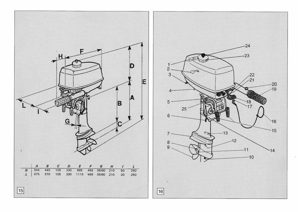
9 TECHNICAL DATA MODEL CORSE CORSE POWER 3.5 HP/2.6 Kw 4 HP/2.9 Kw FULL THROTTLE OPERATING RANGE PISTON DISPLACEMENT BORE X STROKE 49 x x 45 NUMBER OF CYLINDER 1 1 ENGINE TYPE FUEL PUMP Cycle eight two stroke N 1 membrane pump AVERAGE CONSUMPTION 1,3 liters/hour 1,4 liters/hour FUEL Mixture of petrol and "SELVA OUTBOARD MOTOR OIL" (TC-WII) FUEL TANK Incorporated lt. 1.8 RECOMMENDED ENGINE-OIL "SELVA OUTBOARD MOTOR OIL" oil mixed with petrol at 2% IGNITION SPARK LEAD STARTING electronic nautical with capacitive discharge electronic automatic programmed with the engine revolutions manual with rope, which returns automatically on the pulley SPARK PLUGS Bosch W7BC + Champion L87Y - Lodge H - heat range 175 EXHAUST COOLING submarine water cooling with forced circulation caused by a pump PROPELLER REDUCTION RATIO 13/24 GEAR SHIFT LEVER RECOMMENDED GEARBOX-OIL GEARBOX-OIL QUANTITY PROPELLER TYPE TRIM ANGLE ADJUSTING SUSPENSIONS 360 rotation "SELVA OUTBOARD MOTOR GEARBOX OIL" (API GL-5 SAE 80W/90) 95 cc. / 90 gr. anti-weed with three blades 4 positions, which you can select through pin anti vibrations annular shock-absorbers RECOMMENDED HEIGHT OF THE TRANSOMS(mm.) normal shaft long shaft 510 WEIGHT (Kg.) normal shaft 17 - long shaft 17.5 Selva joint-stock CO reserve the right to change weight, construction, materials and characteristics without warning and without therefore having to change the motors, which were built previously. See Picture No. 15 for the dimensions of your motor. 8
10 LOCATION OF MAIN COMPONENTS See picture No. 16 N DESCRIPTION 1 Tilt-up handle and air intake 2 Back cowling lock lever 3 Transport handle 4 Cooling system warning lamp 5 Steering adjustment 6 Trim angle adjusting-rod 7 Anti-cavitation plate 8 Propeller nut 9 Propeller 10 Oil drain plug hole 11 Cooling water inlet 12 Oil level plug hole 13 Anode 14 Swivel bracket 15 Clamp-screws 16 Security stop rope 17 Security stop / stop switch 18 Starting handle 19 Accelerator grip 20 Throttle control adjustment 21 Choke knob 22 Front cowling lock lever 23 Fuel tank cap 24 Event valve on the fuel tank 25 Motor lift cam 9
11 CONTROL FUNCTIONS Security switch / Push-button to stop the motor. Pressing the stop button (red) the ignition circuit is broken and the engine stops immediately. Picture No. 17. Choke knob. Pulling this knob supplies a rich mixture required to start a cold engine. Picture No. 18. Fuel joint Connecting the fast fuel joint, you connect the fuel hose to the fuel tank. Picture No. 19. Recoil starter handle. Pulling this handle starts the engine. Picture No. 20. Motor tilt cam You use this to bloc and unblock the engine in the tilt position Picture No. 24. Clamp-screws. Use them to clamp the outboard motor on the transom Picture No. 25. Steering adjustment grip. With it you can adjust the resistance to steering movement. Screw it to increase resistance. Picture No. 26. Trim angle adjusting-rod. It can be positioned in different holes in order to obtain the appropriate trim angle. Picture No. 27. Throttle-control adjustment. Device which permit to have a constant speed. Picture No. 21. Accelerator-grip/steering-handle. Turn the grip to operate the accelerator, and move it sideways to adjust the steering angle. Picture No. 22. Cowling lock lever. Moving this two levers upwards locks the top cowling. To remove the top cowling push the cowling lock levers downwards Picture No
12 Wiring diagram. Legend 1. Flywheel 2. Ignition-coil 3. Sparking plug. 4. Security stop. Button to stop the motor SYMBOLS see picture No A serious risk is present. The machine operator must read and follow the instructions in the manual. 2. Pull the choke knob. 3. Position of the gear-shift lever. 4. Warning against fire hazard. Picture No Starter-switch for engine. 6. Button to stop the motor 11
13 c THE USE OF OUTBOARD MOTOR PRELIMINARY CONTROLS CHART DETAIL CHECK DESCRIPTION PAGE Complete supply Check that the motor supply includes all the components, that are in the detailed list Check the proper installation of your motor ( the center of the transom) Right installation Check the proper mounting height of your motor. 13 Check the tightness of the clamp screws. 13 Fuel Check the conformity of the fuel to the detailed list. 15 Fuel hose connection Check the proper connection of the fuel hose. 15 Check of the equipment on board Check that you have on board everything necessary to face a possible emergency. Before leaving always check your motor to make sure that it is in a perfect state of efficiency, check its proper and safe functionality. Failure to check as shown in the chart could result in severe injury to people or damage to the boat. If you ever have a question about the operation of your outboard motor, or if you should find any kind of anomaly, please consult a SELVA MARINE dealer. The time which is needed to check your motor is very modest, but the safety, that you obtain from it is enormous 12
14 Check of the supply. When you receive your motor, check that: - the packing is integral - the supply corresponds to the detailed list: 1. the entire motor 2. tool-bag 3. use and maintenance manual 4. certificate of guarantee 5. list of our dealers and our after-sales service 6. registration book (only for the Italian market) 7. CE declaration of conformity - that there is no evident damage. If there is a damage or if parts are missing, you must inform immediately and in detail the forwarding- agent, SELVA joint-stock CO. or its area agents. Picture No. 30. Check that the registration book, the certificate of guarantee and the CE declaration conformity are duly filled in and signed, and that the data written in them correspond to the data printed on the engine s label. c Outboard motor mounting A good position of the motor on the transom is very important to have an appropriate trim angle and therefore to obtain a good performance from your boat To have the optimum mounting height of the outboard motor, you must mount it so that the anti-cavitation plate is between the bottom of the boat and a level of 2 cm below it and it is parallel to it. If the mounting-height is too high, cavitation tends to occur and consequently there will be a falling-off in the performance and a probable overheating of the motor. If the mounting-height is too low, the waterresistance will increase and thereby reduce engine efficiency. Picture No. 31. The motor must be vertical to the water surface and the bracket mounted on a flat even surface and should be fully supported by the top edge of the transom. If the bracket is not fully supported or, if the transom height is too low, a hard wood block should be securely fitted between the bracket and the transom Picture No. 32. Fix the engine in the correct position locking the clamp screws. Picture No
15 Trim angle adjusting The trim angle is the inclination angle, that should be given to the motor in order to obtain an optimal performance from your boat. An improper trim angle does not only affect the performance of your boat, but can also cause loss of control, which means danger for the people on board. c tilt up the motor; bloc the engine in the tilt position turning downwards the engine tilt cam; remove the adjusting-rod and reposition the rod in the desired hole, which allows the appropriate trim angle; lift the engine, unlock the tilt support bar and bring again the motor in the vertical position, so that it leans on the adjustment pin; Improperly distributed load on boat or in different positions, can alter the ideal trim conditions. While sailing the motor should be perpendicular to the water surface, but the trim angle can be 3 degrees to 5 degrees. If the trim angle is made too great, the buoyancy center of the boat will shift towards the stern. In this condition, and if the stability moment at the bow is large, the boat will tend to "porpoise". If the trim angle is insufficient, the bow may "plough", making the boat unstable. When the boat is in stable trim it remains parallel to the water. To adjust the trim angle proceed as follows: You must adjust the trim angle when the engine is switched off. Picture No. 34 Ensure the transom clamp screws are tightened securely close the safety valve of the fuel tank; 14
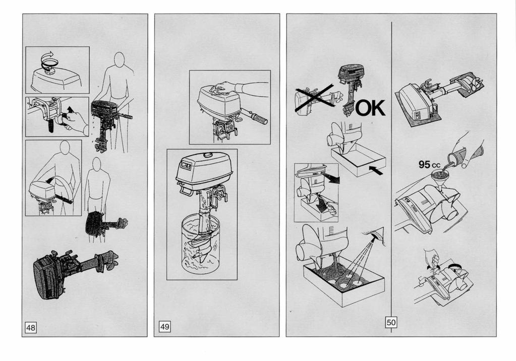
16 FUEL c Preparation of the fuel Fuel The fuel used for the propulsion of internal combustion engines is highly flammable and, in certain cases can become explosive. Refueling and maintenance operations must be done in a well-ventilated area and with the engine stopped. Do not smoke while refueling, keep away from sparks, flames, or other sources of ignition, which could cause fire or explosion. Do not spill gasoline. If gasoline spills, wipe it immediately with dry rags, before starting the motor. Do not overfill the fuel tank, because gasoline expands with the heat and the sun radiation. Tighten the filler cap securely after refueling. Do not let gasoline get into your eyes or onto your skin. Avoid swallowing gasoline or inhaling its vapor. Do not pour fuel off using a pipe. KEEP OUT OF THE REACH OF CHILDREN Use only petrol with an octane number higher than 95 N.O. Research and that does not contain alcohol, with the addition of 2% of oil proper for mixture (see the detailed list) For the motors with incorporated fuel tank it is preferable to use already prepared mixture or you should remove the top cowling and mix the fuel thoroughly by shaking. In this case at the end of this operation, you must check the proper connection of the fast fuel joint, before replacing the cowling. Picture No. 35 It is a good practice, if you use the motor after a break longer than one day, to shake the fuel tank in order to mix oil and petrol thoroughly. Fuel pipe connection To connect the fuel pipe to the incorporated fuel tank you need to link the connection of the pipe to the connection on the fuel tank placed inside the top cowling. Picture No. 36. At this point check the connection by pulling the connection (don t pull the pipe). Picture No. 37. To disconnect pull back the knurled outer ring of the fuel connector which releases the pipe. The pipe s connection must be made when the engine is OFF. Never remove the top cowling when the engine s running. 15
17 STARTING c Verifications when the motor is on Verifications when the engine is OFF Just after starting the motor, you should make sure that : check that the top cowling is locked. Picture No. 38. Make sure that the lock plate is installed on the engine stop switch. Picture No. 39. Starting procedures Loose the safety valve on the fuel tank If your engine is cold, you have to pull the choke knob. Picture No. 40. Place the throttle-grip in the "start" position. Picture No. 41. Pull the starter-handle slowly so that the starter pinion engages with the flywheel. Then give a strong pull, but not too strong, and repeat if necessary the procedure. Picture No. 42. Set the choke knob to home position. Picture No. 43. Pull the starter-handle powerfully until the engine starts. Picture No. 44. You don't need to use the choke-knob, if the engine is warm. If the motor doesn't start after several attempts, you should refer to the troubleshooting section. - after 5/10 seconds, water runs out from the coolingwater pilot-holes. The indicator at the entrance of the circuit, provides only for the proper operation of the pump and not for the circulation of water in the head and in the cylinder. If water does not flow from the pilot-holes check to see if the water-inlets are blocked. Picture No that you do not hear any strange noise; - that the throttle-grip operates in a proper way; - that the engine stop switch operates properly; RUNNING-IN PROCEDURE A SELVA outboard motor is tested completely in our workshop and it is partially run in a tank. A second test is done by the concessionaire It is always advisable to complete the running in procedure in the following way:. During the first 15 running hours you must use a fuel with oil at 3%. 16
18 During the first 3 running hours do not accelerate too much, and during the following navigation hours you can accelerate properly but only for short periods. After about 20 hours you have to change entirely the gearbox-oil (see the greasing sectioning this manual). c A good running in will allow you to obtain a good performance from your motor and a longer endurance of it. STOPPING PROCEDURE Emergency stopping procedures. In an emergency you must stop your motor by pulling the engine stop switch lanyard. To start the motor again you have to install the lock plate again on the engine stop switch. Picture No. 46. Stopping in normal conditions Place the gear-shift lever in the neutral position " N " (neutral gear); accelerate lightly in order to avoid flooding, run the engine again at idling speed and then push the stop button. Picture No. 47. Stopping for a long period of storage. If you will not be using the motor for several days, you should stop the engine in the following way: Run the engine at idling speed, place the gear-shift lever in the neutral position " N "and keep the choke knob pulled until the engine stops. 17
19 OPERATING IN REVERSE GEAR c To run in reverse gear you need to turn the engine through 180 compared to the normal position. When the engine is in reverse position, the motor s lift is automatically prevented by a mechanism. Use the engine in the reverse position only in manoeuvre operations and at low r.p.m. Removal of the motor from the boat Each time that you remove the motor from your boat, you must let it cool down and then carry out the following operations : - close the air vent valve on the fuel tank - release the clamp screws. - lift up the motor vertically and keep it in this position till all the water has run out from the cooling-water passages ( about 1 minute ) - tilt up the steering tiller - transport the motor using the proper handle. - lay down the motor only on its back side. Picture No
20 CLEANING c Cleaning outside SELVA motors do not need much cleaning, to clean the painted parts use a cloth soaked with water While cleaning the cooling water passages make sure that water always circulates in the passages, checking its running out of the pilot hole. Picture No. 49. MAINTENANCE Do not use flammable solvents. Cleaning cooling-water passages Every now and then after using, clean the cooling-water passages, in order to remove mud and salt, so that they do not affect the performance of your motor. You can carry out this cleaning operation in the following way: Immerse the outboard motor without the propeller in a vessel filled up with fresh-water, make sure that the water level is over the height of the water inlets, so that no irreparable damage could be caused to the motor. Shift the gear-shift lever into neutral " N ". Start the engine and run at low speed for a few minutes. Before doing any kind of maintenance or check operation, switch off the engine and wait till it has cooled down, then remove the spark plug cap, in order to avoid an accidental staring. Pay attention to the motor parts, which are still hot, so that you do not burn yourself. Some maintenance operations must be carried out by qualified staff. Contact SELVA MARINE after-sale service. The following chart lists the periodic maintenance operations to do on your motor. The pointed out operations must be done by qualified staff. when you start the engine, the propeller shaft turns. Operate carefully to avoid wounding. Never approach the hands or other objects to the propeller shaft. 19
21 c PERIODIC INSPECTIONS AND ADJUSTMENTS (Running hours) OPERATIONS TO PERFORM Inspection of the conditions of the fuel hoses. If necessary replace them. Check the fuel hose joints for leaks If necessary replace them. Check the proper working of the carburetor. If necessary adjust it. Check, clean and adjust the spark-plugs. If necessary replace them. Check the ignition. Check the head screws and the adjustment to the correct torque. Check the efficiency of the water pump and of the cooling system Check the gearbox-oil level Check the wear of the anode. If necessary replace it. Check the condition of the propeller. If necessary replace it. INITIAL THEREAFTER EVERY Out of season GREASE POINTS Gearbox Bushes of the screw bracket / swivel Cowling levers pins lock Tie rod carburetor levers Propeller shaft Clamp screws GREASING CHART GREASE THAT MUST BE USED API GL-5 SAE 80 W 90 MIL -L 2105 C GREASING FREQUENCY FRESH- WATER SALT WATER Check the level after the first 10 running hours. Afterwards every 50 hours. If necessary add till the marked point. Change the gearbox-oil after the first 20 running hours and afterwards every 100 running hours; and anyway each season. SPRAY LUBRICANT 60 days 30 days SPRAY LUBRICANT 60 days 30 days WATER-REPELLENT MARINE GREASE 60 days 30 days WATER-REPELLENT MARINE GREASE 60 days 30 days WATER-REPELLENT MARINE GREASE 60 days 30 days 20
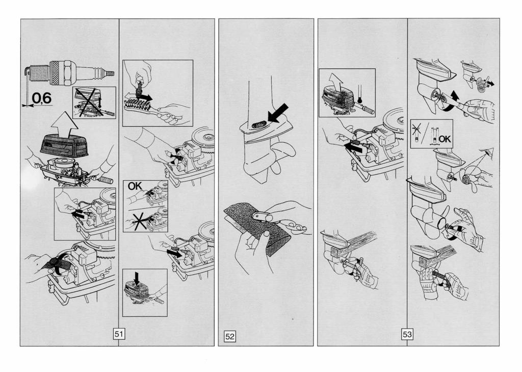
22 Greasing and additions The only part, which must be filled with oil, is the gearbox. Selva supply the motor already with the oil, which the user will have to change completely after the first 20 cruising hours After this change you must check its level every 50 hours and change it every 100 hours, and anyway each season. Gearbox-oil change To change the oil do as follows: Keep the motor in vertical position. Place a container to collect the used oil under the gearbox. Take out the oil-level plug and the oil drain-plug. They have a different size and after the oil change they must be replaced in their proper seat. Wait until the oil has drained completely, (during this operation you must check, if water or other foreign bodies are to be found in the drained oil. They are signs of anomalies which must be identified and repaired by qualified staff, before using the motor again). Protecting the leaning parts, put the motor horizontally, with the oil-level plug and the oil drain-plug holes upwards. Inject the oil into the oil drain-plug hole. The oil must agree with the characteristics listed in the greasing chart, and must comply with the quantity pointed out in the technical detailed list. Insert and tighten the oil-level plug and the oil drain plug. Picture No. 50. c The used oil must be given to the proper collecting centers or to a SELVA service point. Spark-plug The spark-plug must be often inspected because heat and deposits affect its efficiency so that the performance of the motor will be affected too. The inspection of the spark-plug must be done when the engine is not running and it has cooled down. It is very important to check, that the part made of porcelain is not damaged because this could allow external sparks, which could lead to explosion or fire. To remove the spark-plug use the supplied spanner; using an abrasive brush, remove any deposits, then check the wear condition and the spark-plug gap ( the gap must be 0,6 mm, to measure it use a thickness gauge ). If the spark-plug is too badly worn you must replace it with a new one which must agree with the characteristics listed in the specifications chart. The spark-plug torque is 20 Nm ( ~ 2. kgm). If a torque-wrench is not available, you can obtain a good estimate of the correct torque turning the sparkplug completely by hand and then turning it with the spanner, a new spark-plug must be turned ~ 90 and an old one Replace the spark-plug cap, checking that it is correctly fitted and then replace the top cowling. Picture No
23 Sacrificial anode. To protect the motor against electrochemical corrosion, due to the presence in its structure of many different materials, a sacrificial anode has been applied. The anode will be subject to a strong corrosion, so you have to remove the scales from the surfaces of the anode periodically. Failure to clean it, will affect its effectiveness. Do not paint the anode, for this would render it ineffective. When the corrosion compromise its functionality, you have to replace it. Picture No.52 Replacement of the propeller. The propeller is one of the components, which have a great influence upon the performance of the motor. An unsuitable or damaged propeller can cause serious damages to the motor besides reduce the performance. To replace the propeller do as follows: - wait until the motor has cooled down and remove the top cowling; - remove the spark-plug cap, to avoid an accidental start during the operations of replacement of the propeller; ### protect your hands using strong gloves and insert a wooden lump between the propeller blades and the anticavitation plate, to keep the propeller still. ### remove the self stopping nut, the washer and the propeller; ### spread the propeller shaft with water-repellent grease; c ### make sure, that the drive propeller pin is centered on the shaft; ### by hand insert the propeller making sure that it gets correctly into the drive pin; ### insert the washer and by hand screw the self-locking nut; ### insert a wooden lump between the propeller blades and the anti-cavitation plate. ### keep the propeller pressed against the pin and screw tight the nut. Picture No. 53. Storage To help the endurance of your motor, you must carry out properly the following storage operations: Clean the motor and the cooling-water passages. Switch off the engine as shown in the section "stopping for a long period of storage ". Remove the fuel-line connections from the motor. Empty the float chamber. Remove the spark-plug and pour engine-oil into the hole; turn the flywheel by hand to distribute the oil in the cylinder; replace the spark-plug. Change the gearbox-oil. Check the screws torque. Grease all the components as shown in the greasing chart. Inspect the anode. Empty the fuel tank. Store the motor in the vertical position and in a dry, not to cold place. The storage operations must be carried out by qualified staff. 22
24 TROUBLESHOOTING,oo' A B C D E F G H I Possible cause A regular maintenance can help you prevent many problems with your outboard motor. The following chart lists some common difficulties and their possible causes. If you still have difficulties, after investigating these, please contact your SELVA MARINE dealer. A - The engine will not start. B - The engine runs irregularly or stalls. C - The engine idles unevenly. D - Engine speed will not increase. E - The engine is overheating. F - Engine speed is higher than normal. G - Engine speed is lower than normal. H - Boat speed is too low. I - The boat will suddenly slow. Fuel tank is empty Fuel hose is incorrectly connected Fuel hose is flattened or kinked Fuel pump is malfunctioning Improper oil in the fuel Improper petrol Carburetor has a wrong adjustment Incorrect starting procedure Sparks -plugs are fouled. Improper spark-plugs Incorrect spark-plug gap. Spark-plug cap incorrectly fitted Electric circuit is defective 23
25 ,oo' A B C D E F G H I Possible cause Ignition-coil is defective Clogged water passages Faulty water-pump Cavitation is occurring Propeller is damaged Incorrect trim-angle Load on boat is improperly distributed Transom is too high Transom is too low 24
26
27

28

29
30
31
Zadar - Capri OWER'S MANUAL Zadar - Capri
 OWER'S MANUAL Zadar - Capri This manual must be considered as an integral part of your outboard motor and has to be kept with it, also if the motor is resold. Selva joint-stock CO. reserve the right to
OWNER'S MANUAL. Antibes Maiorca
 OWNER'S MANUAL Antibes Maiorca This manual must be considered as an integral part of your outboard motor and has to be kept with it, also if the motor is resold. Selva joint-stock CO. reserve the right
OWNER'S MANUAL. Oyster 5 Oyster 6 Black Bass 7,5 Black Bass "BIG FOOT" 8
 OWNER'S MANUAL Oyster 5 Oyster 6 Black Bass 7,5 Black Bass "BIG FOOT" 8 Vers.02-2006 This manual must be considered as an integral part of your outboard motor and has to be kept with it, also if the motor
Black Bass 8 Oyster "BIG FOOT" 6 Black bass "BIG FOOT" 8 Piranha 9,9
 OWNER'S MANUAL Oyster 6 (inglese) Black Bass 8 Oyster "BIG FOOT" 6 Black bass "BIG FOOT" 8 Piranha 9,9 Vers. 06-2012 This manual must be considered as an integral part of your outboard motor and has to
OWNER'S MANUAL. Madeira St. Tropez Portofino Montecarlo
 OWNER'S MANUAL Madeira St. Tropez Portofino Montecarlo This manual must be considered as an integral part of your outboard motor and has to be kept with it, also if the motor is resold. Selva joint-stock
SUZHOU PARSUN POWER MACHINE CO., LTD.
 OUTBOARD MOTOR OWNER S MANUAL T3.6BM (T2.5BM) SUZHOU PARSUN POWER MACHINE CO., LTD. Thank you for owning a PARSUN outboard motor. Thank you for your trust in our company and products. PARSUN outboard motors
SUZHOU PARSUN POWER MACHINE CO., LTD.
 OUTBOARD MOTOR OWNER S MANUAL T15BM (T9.9BM) SUZHOU PARSUN POWER MACHINE CO., LTD. Thank you for owning a PARSUN outboard motor. Thank you for your trust in our company and products. PARSUN outboard motors
OWNER'S MANUAL. Bull Shark 40xs Bull Shark 50 Tiger Shark 80
 OWNER'S MANUAL Bull Shark 40xs Bull Shark 50 Tiger Shark 80 This manual must be considered as an integral part of your outboard motor and has to be kept with it, also if the motor is resold. Selva joint-stock
OUTBOARD MOTOR OWNER S MANUAL F6ABM F5ABM SUZHOU PARSUN POWER MACHINE CO., LTD.
 OUTBOARD MOTOR OWNER S MANUAL F6ABM F5ABM SUZHOU PARSUN POWER MACHINE CO., LTD. Thank you for owning a PARSUN outboard motor. Thank you for your trust in our company and products. PARSUN outboard motors
OUTBOARD MOTOR OWNER S MANUAL F4BM (F5BM) SUZHOU PARSUN POWER MACHINE CO., LTD
 SUZHOU PARSUN POWER MACHINE CO., LTD") OUTBOARD MOTOR OWNER S MANUAL F4BM (F5BM) SUZHOU PARSUN POWER MACHINE CO., LTD Thank you for owning a PARSUN outboard motor. Thank you for your trust in our company and products. PARSUN outboard motors
OUTBOARD MOTOR OWNER S MANUAL F4BM (F5BM) SUZHOU PARSUN POWER MACHINE CO., LTD Thank you for owning a PARSUN outboard motor. Thank you for your trust in our company and products. PARSUN outboard motors
LAWN MOWER OWNER S MANUAL
 LAWN MOWER OWNER S MANUAL Woodies SKU: 1153279 & 1153280 CAUTION: Read and follow all Safety Rules and Instructions before operating this equipment Thank you for choosing our Gasoline Lawnmower. 1 To ensure
720W PORTABLE GENERATOR
 720W PORTABLE GENERATOR MODEL NO: G720 PART NO: 8857800 OPERATION & MAINTENANCE INSTRUCTIONS LS0214 INTRODUCTION Thank you for purchasing this CLARKE 720W Portable Generator Before attempting to use this
FORZA BOLT OUTBOARD MOTOR OWNER S MANUAL
 FORZA BOLT OUTBOARD MOTOR OWNER S MANUAL Table Of Contents 1.Introduction...1 2.Safety Information.1 3.Refuelling Information...1 4.Safety Matters 2 5.Preparation.3 6.Operation.3 7.Maintenance...4 8.Storage...5
1100W PORTABLE GENERATOR
 1100W PORTABLE GENERATOR MODEL NO: G1200 PART NO: 8010110 OPERATION & MAINTENANCE INSTRUCTIONS LS0312 INTRODUCTION Thank you for purchasing this CLARKE 1100W Portable Generator. Before attempting to use
OUTBOARD MOTOR OWNER S MANUAL F9.8BM F8BM F6BM SUZHOU PARSUN POWER MACHINE CO., LTD
 OUTBOARD MOTOR OWNER S MANUAL F9.8BM F8BM F6BM SUZHOU PARSUN POWER MACHINE CO., LTD Thank you for owning a PARSUN outboard motor. Thank you for your trust in our company and products. PARSUN outboard motors
OUTBOARD MOTORS OWNER S MANUAL F15A BM/BW/FW F20A BM/BW/FW SUZHOU PARSUN POWER MACHINE CO., LTD.
 OUTBOARD MOTORS OWNER S MANUAL F15A BM/BW/FW F20A BM/BW/FW SUZHOU PARSUN POWER MACHINE CO., LTD. Thank you for owning an outboard motor. Thank you for your trust in our company and products. The outboard
1200W INVERTER GENERATOR
 1200W INVERTER GENERATOR MODEL NO: IG1200 PART NO: 8877070 OPERATION & MAINTENANCE INSTRUCTIONS LS0117 INTRODUCTION Thank you for purchasing this CLARKE 1200W Inverter Generator. Before attempting to use
AIR-COOLED DIESEL GENERATOR OWNERʼS MANUAL. This manual contains important safety information. TDG2500E TDGW7000E TDG7000SE TDG4500E
 AIR-COOLED DIESEL GENERATOR OWNERʼS MANUAL This manual contains important safety information. TDG2500E TDGW7000E TDG7000SE TDG4500E TDG8000-3 TDG7000SE-3 TDG7000E TDG8000E TDGW7000SE TDG7000E3 TDGW8000E
IMPORTANT INFORMATION
 Table of Contents IMPORTANT INFORMATION Section 1B - Maintenance MAINTENANCE 1 B Specifications................................ 1B-1 Special Tools................................ 1B-2 Quicksilver Lubricant/Sealant..................
Owner s/operator s Manual
 Water Pump MP2533E2 Owner s/operator s Manual Completely read and understand this manual before using this product. Foreword This Owner s/ Operator s Manual is designed to familiarize the operator with
HOT WASHER MODEL NO: KING 125 OPERATION & MAINTENANCE INSTRUCTIONS PART NO: LS1009
 HOT WASHER MODEL NO: KING 125 PART NO: 7320170 OPERATION & MAINTENANCE INSTRUCTIONS LS1009 INTRODUCTION Thank you for purchasing this Hot Washer. This machine is a portable, high pressure power washer,
PF-4000, PF-4010, PF-4210 MULTI-PURPOSE ENGINE
 PF-4000, PF-4010, PF-4210 MULTI-PURPOSE ENGINE Date 09-26-01 Supplier To The Outdoor Power Equipment Industry ISM, Inc. 1028 4 th Street SW Auburn, WA 98001 Phone: (253) 333-1200 Fax: (253) 333-1212 WWW.TANAKA-USA.COM
KING CANADA 950W PORTABLE GENERATOR MODEL: KCG-951G INSTRUCTION MANUAL COPYRIGHT 2011 ALL RIGHTS RESERVED BY KING CANADA TOOLS INC.
 KING CANADA 950W PORTABLE GENERATOR MODEL: KCG-951G INSTRUCTION MANUAL COPYRIGHT 2011 ALL RIGHTS RESERVED BY KING CANADA TOOLS INC. WARRANTY & SERVICE INFORMATION 1-YEAR LIMITED WARRANTY FOR THIS 950W
Light condition and operation Windshield glass condition Wiper blade condition Paint condition and corrosion Fluid leaks Door and hood lock condition
 GENERAL CHECKS Engine Compartment The following should be checked regularly: Engine oil level and condition Transmission fluid level and condition Brake fluid level Clutch fluid level Engine coolant level
RedGum GP160 Splitter. Owner s Manual
 RedGum GP160 Splitter Owner s Manual Product Description & Intended Purpose: This Log Splitter / Wood Splitter is an outdoor product that splits wood logs for use as fuel in a fireplace or a woodstove.
Gasoline Inverter Generator
 user manual Gasoline Inverter Generator table of contents Preface Introduction... Safety Information Exhaust fumes are poisonous... Fuel is highly flammable and poisonous... Engine and muffler may be hot...
Parsun Portable 4-Stroke Outboard Motor Winterize or Storing DIY Service Guide
 Parsun Portable 4-Stroke Outboard Motor Winterize or Storing DIY Service Guide To help keep your engine in tip-top condition for years to come, it is important that you winterize your outboard for off-season
4. FUEL SYSTEM CK 1 4-0
 4 4 4-0 SERVICE INFORMATION... 4-1 FLOAT LEVEL INSPECTION... 4-5 TROUBLESHOOTING... 4-2 CARBURETOR INSTALLATION... 4-6 THROTTLE VALVE DISASSEMBLY... 4-3 THROTTLE VALVE ASSEMBLY... 4-6 CARBURETOR REMOVAL...
WARNING! Ensure that there are no naked flames around the product! Do not smoke while filling fuel and oil!
 Engine Oil and Fuel Engine Operation This product is equipped with a 4 stroke engine. Before operation you have to add proper fuel and engine oil. DO NOT MIXTURE THEM! 1. Place the product on a stable,
IMPORTANT: Read this manual fully before assembly and use and observe all safety rules and operating instructions
 PETROL ENGINE Model: MLR52 IMPORTANT: Read this manual fully before assembly and use and observe all safety rules and operating instructions Contents Technical Specification 2 Safety 3 Starting 5 Running
Engine oil. Introduction. Warning and indicator lights WARNING
 Engine oil Introduction In this section you ll find information about: Warning and indicator lights Engine oil specifications Engine oil capacities Checking the engine oil level and adding oil Engine oil
5.5KVA GENERATOR MODEL NO: PG6500DVES OPERATION & MAINTENANCE INSTRUCTIONS PART NO: LS0616
 5.5KVA GENERATOR MODEL NO: PG6500DVES PART NO: 8857810 OPERATION & MAINTENANCE INSTRUCTIONS LS0616 INTRODUCTION Thank you for purchasing this CLARKE 5.5KVA Generator. Before attempting to use this product,
3. INSPECTION/ADJUSTMENT
 3 3 INSPECTION/ADJUSTMENT SERVICE INFORMATION -------------------------------------------- 3-1 MAINTENANCE SCHEDULE ---------------------------------------- 3-2 FUEL LINE/FUEL FILTER -------------------------------------------
INSPECTION/ADJUSTMENT
 3 3 INSPECTION/ADJUSTMENT SERVICE INFORMATION----------------------------------------------------------------------- 3-1 MAINTENANCE SCHEDULE-------------------------------------------------------------------
OUTBOARD MOTOR OWNER S MANUAL T40/30BM T40/30BW T40/30FW SUZHOU PARSUN POWER MACHINE CO., LTD.
 OUTBOARD MOTOR OWNER S MANUAL T40/30BM T40/30BW T40/30FW SUZHOU PARSUN POWER MACHINE CO., LTD. Thank you for owning a PARSUN outboard motor. Thank you for your trust in our company and products. PARSUN
GENERATOR MODEL NO: FG3000 OPERATION & MAINTENANCE INSTRUCTIONS PART NO: LS0609
 GENERATOR MODEL NO: FG3000 PART NO: 8857700 OPERATION & MAINTENANCE INSTRUCTIONS LS0609 INTRODUCTION Thank you for purchasing this CLARKE Generator. Before attempting to use this product, please read this
DIAPHRAGM PUMPS: Instruction Manual
 INTRODUCTION DIAPHRAGM PUMPS: Instruction Manual Congratulations for choosing a product Imovilli Pompe, the result of a careful manufacturing process supported by over fifty years of specific experience
OPERATION & MAINTENANCE INSTRUCTIONS
 WARNING Read the instructions before using the machine PETROL DRIVEN POWER WASHER MODEL NO: TIGER1700 PART NO: 7320054 OPERATION & MAINTENANCE INSTRUCTIONS LS0511 2 INTRODUCTION Thank you for purchasing
OWNERS MANUAL. Two Stroke Dirt Bike. Distributed by SSR Motorsports. Address: Alondra Blvd, Norwalk CA
 OWNERS MANUAL Two Stroke Dirt Bike Distributed by SSR Motorsports Address: 12825 Alondra Blvd, Norwalk CA 90650 www.ssrmotorsports.com Please note that this is a general manual. The model of the vehicle
Operation Manual. 21 Inch Self-Propelled Lawn Mower MODEL #
 21 Inch Self-Propelled Lawn Mower MODEL # 106461 Operation Manual This safety alert symbol identifies important safety messages in this manual. Failure to follow this important safety information may result
GENERATOR MODEL NO: FG3005 OPERATION & MAINTENANCE INSTRUCTIONS PART NO: LS0413
 GENERATOR MODEL NO: FG3005 PART NO: 8857707 OPERATION & MAINTENANCE INSTRUCTIONS LS0413 INTRODUCTION Thank you for purchasing this CLARKE Generator. Before attempting to use this product, please read this
YK1900i DIGITAL INVERTER GASOLINE GENERATOR OWNER S MANUAL PLEASE READ THIS MANUAL CAREFULLY. IT CONTAINS IMPORTANT SAFETY INFORMATION.
 YK1900i DIGITAL INVERTER GASOLINE GENERATOR OWNER S MANUAL PLEASE READ THIS MANUAL CAREFULLY. IT CONTAINS IMPORTANT SAFETY INFORMATION. PREFACE Thank you for purchasing YANGKE generator. This manual covers
GENERATOR MODEL NO: FG2500 OPERATION & MAINTENANCE INSTRUCTIONS PART NO: LS0114
 GENERATOR MODEL NO: FG2500 PART NO: 8857727 OPERATION & MAINTENANCE INSTRUCTIONS LS0114 INTRODUCTION Thank you for purchasing this CLARKE Generator. Before attempting to use this product, please read this
ENGINE DRIVEN 3 FULL TRASH PUMP
 ENGINE DRIVEN 3 FULL TRASH PUMP MODEL NO: PF75 PART NO: 7230165 OPERATION & MAINTENANCE INSTRUCTIONS ORIGINAL INSTRUCTIONS LS0117 ISS 2 INTRODUCTION Thank you for choosing this Clarke Pump. The function
5. FUEL SYSTEM FUEL SYSTEM 5-0
 5 FUEL SYSTEM 5-0 SERVICE INFORMATION GENERAL INSTRUCTIONS SERVICE INFORMATION...5-1 CARBURETOR INSTALLATION...5-9 TROUBLESHOOTING...5-1 PILOT SCREW ADJUSTMENT...5-10 CARBURETOR REMOVAL...5-2 AUTO BYSTARTER...5-3
5. FUEL SYSTEM 5-0 FUEL SYSTEM MXU 250R/300R
 5 FUEL SYSTEM 5 SERVICE INFORMATION------------------------------------------------ 5-2 TROUBLESHOOTING----------------------------------------------------- 5-3 FUEL TANK -----------------------------------------------------------------
Water pump Owner's Manual
 Water pump Owner's Manual Safety Precautions I. General Safeguards Please read this operation manual to have a thorough understanding of the content there before use the product. Failure to do so may lead
3KVA DUAL VOLTAGE GENERATOR MODEL NO: PG3800DV
 3KVA DUAL VOLTAGE GENERATOR MODEL NO: PG3800DV PART NO: 8857815 OPERATION & MAINTENANCE INSTRUCTIONS LS1016 INTRODUCTION Thank you for purchasing this CLARKE 3KVA Dual Voltage Generator. Before attempting
IMPORTANT INFORMATION
 Table of Contents IMPORTANT INFORMATION Section 1B - Maintenance MAINTENANCE 1 B Specifications........................... 1B-1 Special Tools........................... 1B-2 Mercury/Quicksilver Lubricants
Instruction Manual. Vibratory Plate Compactor
 Instruction Manual Vibratory Plate Compactor Model VPC45R Model VPC65R Model VPC85R Model VPC95R Table of Contents 1. INTRODUCTION...1 2. SAFETY...1-2 3. SPECIFICATIONS.....2 4. APPLICATION.. 2 5. CHECK
Carburetor Instructions
 Carburetor Instructions for HUDSON SUPER SIX ESSEX SIX CYLINDER Hudson Motor Car Co. DETROIT, U.S.A. Carburetor The carburetor is a device for metering correct amounts of fuel and air for the various
142F 144F GASOLINE ENGINE SM-142F-01A INSTRUCTION MANUAL
 142F 144F GASOLINE ENGINE SM-142F-01A INSTRUCTION MANUAL Thank you for purchasing our engine. This manual covers the operation and maintenance of your engine. All information in this publication is base
WEBER CARBURETOR TROUBLESHOOTING GUIDE
 This guide is to help pinpoint problems by diagnosing engine symptoms associated with specific vehicle operating conditions. The chart will guide you step by step to help correct these problems. For successful
Electric Trolling Motor
 Electric Trolling Motor L Series User s Manual Please read and retain this manual before using product REACH RoHS TABLE OF CONTENTS Contents GENERAL INFORMATION 4 SPECIFICATIONS 4 WIRING AND BATTERY RECOMMENDATIONS
The engine exhaust from this product contains chemicals known to the State of California to cause cancer, birth defects, or other reproductive harm.
 The engine exhaust from this product contains chemicals known to the State of California to cause cancer, birth defects, or other reproductive harm. Keep this owner s manual handy, so you can refer to
The engine exhaust from this product contains chemicals known to the State of California to cause cancer, birth defects, or other reproductive harm.
 C 2003 Honda Motor Co., Ltd. -All Rights Reserved 2004 The engine exhaust from this product contains chemicals known to the State of California to cause cancer, birth defects, or other reproductive harm.
Instruction Model 18537
 Instruction 738-556 Model 18537 LIMITED WARRANTY H. D. Hudson Manufacturing Company warrants to the original purchaser only that this product will continue to function as intended if used in accordance
FUEL SYSTEM. Table of Contents. Specifications. Section 3A Fuel Delivery System. Models 6/8/9.9/10/15 CARBURETOR SPECIFICATIONS
 FUEL SYSTEM Section 3A Fuel Delivery System Table of Contents Specifications............................. 3A-1 WMC Carburetor Specifications............. 3A-2 WMC Carburetor Specifications.............
CARBURETOR SERVICE INFORMATION TROUBLESHOOTING THROTTLE VALVE DISASSEMBLY THROTTLE VALVE INSTALLATION...
 11 CARBURETOR SERVICE INFORMATION... 11-2 TROUBLESHOOTING... 11-2 THROTTLE VALVE DISASSEMBLY... 11-3 THROTTLE VALVE INSTALLATION... 11-4 CARBURETOR REMOVAL... 11-5 AUTO BYSTARTER... 11-6 FLOAT CHAMBER...
4. FUEL SYSTEM 4-0 FUEL SYSTEM NEXXON 50
 4 FUEL SYSTEM SERVICE INFORMATION ------------------------------------------------ 4-2 TROUBLESHOOTING----------------------------------------------------- 4-3 AIR CLEANER REMOVAL -----------------------------------------------
12. CARBURETOR 12-0 CARBURETOR VITALITY 50
 12 12 CARBURETOR SERVICE INFORMATION (2-STROKE)... 12-2 SERVICE INFORMATION (4-STROKE)... 12-3 THROTTLE VALVE (2-STROKE)... 12-5 CARBURETOR (2-STROKE)... 12-7 AIR SCREW ADJUSTMENT (2-STROKE)... 12-13 REED
Table of Contents. Safety symbols... 3 Assembly 6. Operation Maintenance Troubleshooting 11. Storage. 12. Notes. 13
 Table of Contents Safety symbols... 3 Assembly 6 Operation... 8 Maintenance... 10 Troubleshooting 11 Storage. 12 Notes. 13 2 Safety Information Attention; this machine can be dangerous! All operators should
TP300 INDUSTRIAL TRASH PUMP OPERATOR S MANUAL
 TP300 INDUSTRIAL TRASH PUMP OPERATOR S MANUAL IT IS EXTREMELY IMPORTANT TO READ AND UNDERSTAND THE ENTIRE CONTENTS OF THIS OPERATOR S MANUAL BEFORE ATTEMPTING TO OPERATE THE PRODUCT. THIS EQUIPMENT IS
BF25D BF30D Owner s Manual
 BF25D BF30D Owner s Manual 2004 Honda Motor Co., Ltd. -All Rights Reserved 2005 The engine exhaust from this product contains chemicals known to the State of California to cause cancer, birth defects,
AG-HA-2500N GASOLINE GENERATOR
 AG-HA-2500N GASOLINE GENERATOR OWNER S MANUAL BEFORE OPERATING THIS EQUIPMENT PLEASE READ THESE INSTRUCTIONS CAREFULLY (I)WARNING 1. Read the operator s instruction manual. 2. Attention! Exhaust gases
FSG175 FENCE STAPLE GUN
 Kencove Farm Fence Supplies 344 Kendall Rd Blairsville, PA 15717 1-800-KENCOVE sales@kencove.com www.kencove.com OPERATING MANUAL FSG175 FENCE STAPLE GUN To reduce the risk of possible injury, read the
OWNER S MANUAL BFT 200A 225A
 OWNER S MANUAL BFT 200A 225A The engine exhaust from this product contains chemicals known to the State of California to cause cancer, birth defects, or other reproductive harm. Keep this Owner s Manual
The engine exhaust from this product contains chemicals known to the State of California to cause cancer, birth defects, or other reproductive harm.
 The engine exhaust from this product contains chemicals known to the State of California to cause cancer, birth defects, or other reproductive harm. Keep this owner s manual handy, so you can refer to
5. FUEL SYSTEM 5-0 FUEL SYSTEM UXV 500
 5 FUEL SYSTEM 5 SERVICE INFORMATION------------------------------------------------ 5-02 TROUBLESHOOTING----------------------------------------------------- 5-03 FUEL TANK -----------------------------------------------------------------
INSTRUCTION MANUAL GASOLINE BRUSH CUTTER TR L. 42.7cc. 1.3 kw. 450 mm. Note : Read and carefully before using this machine
 INSTRUCTION MANUAL GASOLINE BRUSH CUTTER TR15142 Note : Read and carefully before using this machine 42.7cc 1.3 kw 450 mm 18" 0.70 L MANUAL SAFETY SYMBOLS AND IMPORTANT INFORMATION This symbol accompanied
3. INSPECTION/ADJUSTMENT
 3 SERVICE INFORMATION...3-0 FINAL REDUCTION GEAR OIL...3-7 MAINTENANCE SCHEDULE...3-2 DRIVE BELT...3-7 FUEL FILTER...3-3 BRAKE SHOE...3-8 THROTTLE OPERATION...3-3 BRAKE ADJUSTING NUT...3-8 AIR CLEANER...3-4
The engine exhaust from this product contains chemicals known to the State of California to cause cancer, birth defects, or other reproductive harm.
 The engine exhaust from this product contains chemicals known to the State of California to cause cancer, birth defects, or other reproductive harm. Keep this Owner s Manual handy, so you can refer to
1P88F-1 1P90F-1 1P92F-1. Owner's Manuel
 1P88F-1 1P90F-1 1P92F-1 Owner's Manuel EN 1 TABLE OF CONTENTS 1. General information... 1 2. Safety regulations... 1 3. Components and controls... 2 4. What you need to know... 3 5. Standards of use...
Airless Spray Gun INSTRUCTIONS DP psi (345 bar) Maximum Working Pressure
 Maximum Working Pressure") INSTRUCTIONS DP-6376 Airless Spray Gun 5000 psi (345 bar) Maximum Working Pressure INSTRUCTIONS This manual contains important warnings and information. READ AND KEEP FOR REFERENCE. Table of Contents Warnings......................................
INSTRUCTIONS DP-6376 Airless Spray Gun 5000 psi (345 bar) Maximum Working Pressure INSTRUCTIONS This manual contains important warnings and information. READ AND KEEP FOR REFERENCE. Table of Contents Warnings......................................
No part of this publication may be reproduced without written permission.
 Thank you for purchasing a Honda generator. This manual covers operation and maintenance of the EB3000 and EB4000 generators. All information in this publication is based on the latest product information
 OWNERS MANUAL www.prodriveoutboards.com PO Box 949 129 S Main St. Loreauville, LA PH#: 337-229-0034 FAX#: 337-229-2302 1 TO THE OWNER Thank you for purchasing a Pro-Drive Shallow Water Outboard. Your unit
NOTES FOR SAFETY OPERATOR-ONLY.
 NOTES FOR SAFETY Both the parents and their child must fully understand everything in this manual before riding. This vehicle is for OPERATOR-ONLY. This vehicle is only designed for operation on level,
Version 1.4 Operating instructions Czech Republic
 Version 1.4 Operating instructions Czech Republic Please check updates of operating instructions at www.rotomotor.cz, that your engine has still the best care. (can happen important changes that will lead
North Dakota State University Grounds Maintenance Equipment
 North Dakota State University Grounds Maintenance Equipment I. Introduction Grounds maintenance equipment is an important part of the work activities on NDSU campus. They can make grounds maintenance jobs
SECTION 6 2 SERVICE PROCEDURES AND SPECIFICATIONS. Engine. Specifications
 SERVICE PROCEDURES AND SPECIFICATIONS Engine SECTION 6 2 Specifications........................................... 170 Fuel.................................................... 172 Facts about engine oil
Pump Operating and Maintenance Manual - Models
 Pump Operating and Maintenance Manual - Models 78-00111 - 78-0057 Thank you for purchasing the SDI Diaphragm Pump manufactured by Comet Pump. Comet produces quality products which are safe, efficient and
WARNING: Read these instructions before using the machine GENERATOR MODEL NO: IG3500F PART NO: OPERATION & MAINTENANCE INSTRUCTIONS
 WARNING: Read these instructions before using the machine GENERATOR MODEL NO: IG3500F PART NO: 8877100 OPERATION & MAINTENANCE INSTRUCTIONS ORIGINAL INSTRUCTIONS LS0217 INTRODUCTION Thank you for purchasing
HOFFMANN POWER PRODUCTS PARTS LIST 2014
 HOFFMANN POWER PRODUCTS PARTS LIST 2014 VIBRATORY PLATE COMPACTOR ALL PARTS ARE SUBJECT TO STANDARD HOFFMANN TERMS AND CONDITIONS OF SALE 2010 Replacement parts are not manufactured, sold or warranted
SECTION 6 2 SERVICE PROCEDURES AND SPECIFICATIONS. Engine. Specifications
 SERVICE PROCEDURES AND SPECIFICATIONS Engine SECTION 6 2 Specifications........................................... 162 Fuel.................................................... 164 Facts about engine oil
Part No FJ180V KAI. 4-stroke air-cooled gasoline engine OWNER, S MANUAL
 Part No. 99920-2280-02 FJ180V KAI 4-stroke air-cooled gasoline engine OWNER, S MANUAL SAFETY AWARENESS FOREWORD TABLE OF CONTENTS Whenever you see the symbols shown below, heed their instructions! Always
Spa USE AND MAINTENANCE CULTIVATOR MODEL BL300 / BL350
 Spa USE AND MAINTENANCE CULTIVATOR MODEL BL300 / BL350 02/12/2008 INDEX INTRODUCTION TECHNICAL DETAILS GENERAL SAFETY REGULATIONS STARTING AND STOPPING USE AND ADJUSTMENT SERVICING TESTS FOR CE REGULATIONS
Operation Manual. 10 Mini-Cultivator MODEL #
 10 Mini-Cultivator MODEL # 103350 Operation Manual This safety alert symbol identifies important safety messages in this manual. Failure to follow this important safety information may result in serious
ATD-6810 SPRAY GUN W/CUP INSTRUCTION MANUAL
 ATD-6810 SPRAY GUN W/CUP INSTRUCTION MANUAL Read this Instruction Manual carefully and understand it completely, basic precaution should be strictly followed to prevent the damage to the tool and injury
COLT 2310, 2510, AND 2712 COM PACT TRACTORS CHAPTER 9 TROUBLESHOOTING AND ANALYSIS
 COLT 2310, 2510, AND 2712 COM PACT TRACTORS CHAPTER 9 TROUBLESHOOTING AND ANALYSIS 9-A-1 UPON RECEIVING ANENGINE FORRE- PAIR. Learn the history of the unit from the customer. While the customer is present
REMOTE CONTROL CONVERSION KIT, P/N INSTALLATION INSTRUCTIONS
 REMOTE CONTROL CONVERSION KIT, P/N 5035779 INSTALLATION INSTRUCTIONS APPLICATION This kit is designed for use on 003 (ST) and newer Johnson 4, 5, 6 HP (38 cc) 4-Stroke outboards. DO NOT install on any
Earth Auger MAG500 MAG500RS
 Earth Auger MAG500 MAG500RS US Owner s/operator s Manual Completely read and understand this manual before using this product. - 0 - Foreword This Owner s/ Operator s Manual is designed to familiarize
AIR COMPRESSOR OPERATING INSTRUCTION AND PARTS LIST
 AIR COMPRESSOR OPERATING INSTRUCTION AND PARTS LIST BELT TYPE IMPORTANT PLEASE MAKE CERTAIN THAT THE PERSON WHO IS TO USE THIS EQUIPMENT CAREFULLY READS AND UNDERSTANDS THESE INSTRUCTIONS BEFORE STARTING
Voltmaster Centrifugal Trash Pumps
 Voltmaster Centrifugal Trash Pumps Model TSP2, TSP3 and TSP4 Owner s Manual February 2011 Table of Contents 1 Introduction............................ 1 1.1 Read before using..................... 1 1.2
OWNER S MANUAL BFT 60A BFW 60A
 OWNER S MANUAL BFT 60A BFW 60A The engine exhaust from this product contains chemicals known to the State of California to cause cancer, birth defects, or other reproductive harm. Keep this Owner s Manual
Operation and Maintenance Instructions for the RAPTOR 178
 WWW.SKYTOY.COM Operation and Maintenance Instructions for the RAPTOR 178 See www.skytoy.com for updates and service bulletins. 2/1/2011 1. Parts Schematic:... 3 2. Muffler Assembly Diagram:... 4 3. Muffler
February 26, ch.12.notebook. Ch. 12. Preventative Maintenance and Troubleshooting. Feb 23 5:03 PM
 Ch. 12 Preventative Maintenance and Troubleshooting Feb 23 5:03 PM 1 Why PM? preventive maintenance certain maintenance tasks must be performed regularly to keep an engine working properly helps premature
FORZA BOSS OUTBOARD MOTOR
 FORZA BOSS OUTBOARD MOTOR Table of Contents 1. Safety Information.....1 2. Product Features and Operation... 2 3. Technical Features and Specifications......6 4. Overall Dimensions...8 5. Installation..........8
OWNER S MANUAL BFT 75A 90A
 OWNER S MANUAL BFT 75A 90A The engine exhaust from this product contains chemicals known to the State of California to cause cancer, birth defects, or other reproductive harm. Keep this Owner s Manual
Owner s Manual ELECTRIC GENERADORS R7100DP / G7100G
 Owner s Manual ELECTRIC GENERADORS R7100DP / G7100G Thank you for choosing a generator set of our company. This manual contains the information on how to do that. Please read it carefully before operating.
Recommended fuel. Recommended engine oil. Gearbox oil. Engine s fuel and oil capacity. Fuel consumption SAE 10W30 SAE 80W90
 TROUBLESHOOT ZONE USEFUL INFORMATION Recommended fuel Lead-free petrol USA: Pump octane number of 86 or higher. Non-USA: Research octane number of 91 or higher Pump octane number of 86 or higher. We recommend