Black Bass 8 Oyster "BIG FOOT" 6 Black bass "BIG FOOT" 8 Piranha 9,9
|
|
|
- Scot Jennings
- 5 years ago
- Views:
Transcription
1 OWNER'S MANUAL Oyster 6 (inglese) Black Bass 8 Oyster "BIG FOOT" 6 Black bass "BIG FOOT" 8 Piranha 9,9 Vers
2 This manual must be considered as an integral part of your outboard motor and has to be kept with it, also if the motor is resold. Selva joint-stock CO. reserve the right to change its product at any moment, except for the essential specifications, which will be kept as they are. Any reference to products or details of a third party has only an informative purpose and it doesn't represent an obligation. Selva joint-stock CO. doesn't take on any responsibility concerning the performance or the employment of these products. We are glad that you have chosen a SELVA MARINE product, which means quality, technology and careful research. Your choice will give you many advantages, which you will soon learn to appreciate. Our dealers, our after-sales service and the guarantee, which you have signed, together with the observance of the information contained in this owner's manual are the essential conditions to give your recent purchase a long life. Your holiday, your favourite sport, your job, which has from today the name SELVA MARINE, will be a further moment of satisfaction. This manual belongs to Selva joint-stock CO. All rights reserved. Any partial or total reprinting without the permission is prohibited. 1
3 INTRODUCTION Before operating this outboard motor, read this Owner's Manual carefully and completely, pay attention especially to the safety measures and rules. Your safety and other people's safety do not depend only on your ability at using the motor, but they depend also on your knowledge and on the efficiency of the motor as well as on the respect of the laws and regulations relating to the use of outboard motors. We suggest you improve your knowledge of the motor so that you can sail with mastery and confidence. If any kind of repair on the motor should not have been clearly described in this manual or if you want to order spare parts or accessories, or if you have any question about the operation or maintenance of your outboard motor, please consult an authorised SELVA MARINE service station or SELVA MARINE dealer ATTENTION Pay attention to all the particularly important information that in this manual are distinguished in the following ways : Safety measures and rules, which protect the machine operator and other people from serious accidents or risks. Directions or special precautions that must be taken to avoid damage to the outboard motor or personal accidents. Directions that make procedures easier or clearer. Technical information. 2
4 OUTBOARD MOTOR IDENTIFICATION DATA This data is stamped on the label attached on the clamp bracket, as shown on the picture 1. When you receive your new SELVA outboard motor write down the serial number, it will be useful to you in case you will have to order spare parts or for reference if your outboard motor should be stolen. SERIAL NUMBER RECORD Write down the identification number and the model of your outboard motor in the spaces below. MODEL Make sure that the data on the label is the same as the data written in your registration book. Picture No.1 SERIAL NUMBER Do not install an outboard motor with more horsepower than shown in the certification of your boat. 3
5 CONTENTS GENERAL INFORMATION... 1 Introduction... 2 Outboard motor identification data... 3 Serial number record... 3 Directions for use. Basic safety measures... 5 Specifications... 8 Location of main components Remote control box Control functions Wiring diagram Symbols THE USE OF OUTBOARD MOTOR Preliminary controls chart Check of the supply Outboard motor mounting Remote control box installation Battery mounting Trim angle adjusting Fuel Fuel Type of fuel Fuel tank clamping and pipes connection Use of the remote control box Starting Verifications before starting the motor Starting procedures Verifications when the motor is on Emergency starting procedures Running-in procedure Navigation Responsibility during the navigation Shallow water cruising Tilt-up the motor Stopping procedure Emergency stopping procedures Stopping in normal conditions Stopping for a long period of storage Removal of the motor from the boat Cleaning Cleaning outside Cleaning cooling-water passages MAINTENANCE Introduction Periodic inspections and adjustments chart Greasing chart Greasing and additions Motor oil Motor oil change Gearbox oil Gearbox-oil change Motor oil filter replacement Spark-plug Sacrificial anode Replacement of the propeller Storage TROUBLESHOOTING Troubleshooting chart EXPLANATORY PICTURES
6 DIRECTIONS FOR USE BASIC SAFETY MEASURES To use the outboard motor you must have all requisites provided by law (physical suitability, insurance, government duties, registration, and so on). We suggest you become familiar with your boat equipped with SELVA motor in places, which are not too crowded. Taking some medicines, alcoholic drinks or drugs increase considerably the risk of accidents. Make sure that you are in a physical condition suitable for driving. Pay attention to tiredness and sleepiness. The engine operator should not let his mind wander, or be distracted or influenced by other people, things or actions,(do not smoke, eat, read, and so on.) while steering the boat. Use fuels and oils suitable for the engine, which are listed in the "greasing chart ". Check every so often the oil level and the fuel level. Stop the motor before every kind of maintenance or cleaning procedures, and in case of complicated maintenance take the spark-plug cap out. Picture No. 2. Before opening the top cowling, wait till the engine has cooled down. Do not open the top cowling, when the engine is running. Picture No. 3. 5
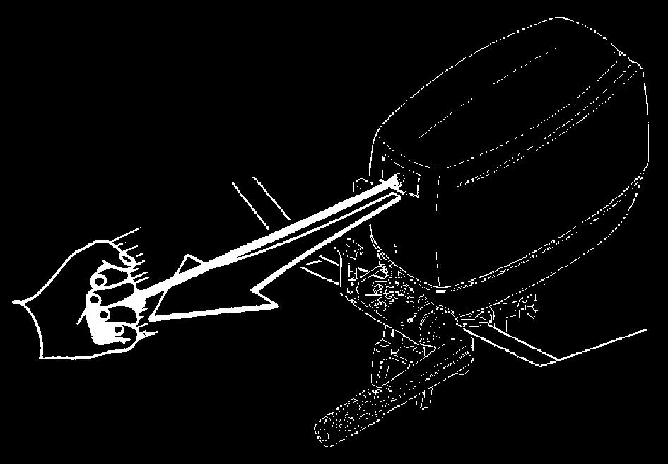
7 PAY ATTENTION TO THE PROPELLER The propeller is certainly the least protected part of your motor. It is therefore forbidden to get near the propeller when this is in rotating. You must give bathers, skiers and other boat users enough space to move, in order to avoid any contact with the propeller. Picture No. 4. The engine operator must attach the engine stop switch lanyard to his wrist when the motor is on. Picture No. 5. Never sit on the motor. Picture No. 6. There must be nobody within the motor steering radius. Picture No. 11. The free lock lever must always be engaged while the motor is in motion. Never tilt-up the motor out of the water, while it is in motion. Picture No. 12. Never pull the recoil starter handle, while the motor is running. Picture No. 13. Never change the inclination angle of your motor using the steering rod, but use the proper handle. Picture No. 7. The motor must always have its top cowling on, when it is operating Picture-No. 8. When you connect the fuel joint, check the proper connection. Picture No. 9. When starting there must be nobody within the engine operator's action radius. Picture No. 10. To transport the motor use only the proper handle. Before transporting the motor you have to tilt-up the steering rod properly. The fuel tank is also provided with a handle to use for the transport. Picture No. 14. When starting or operating the engine, do not touch electrical parts and particularly the ignition-coil, the high voltage wire, the spark-plug cap and the spark-plug itself. When opening the safety valve of the fuel tank, highly flammable vapours come out. Do not smoke, inhale or use open flames close to it. 6
8 If the motor has had an accident, you should have it fully checked, before you use it again. If necessary let the SELVA MARINE authorised skilled staff have a look at it. Do not use the motor, as the damage could have compromised the sailing safety. Prevent fires and explosions. Before operating an outboard motor, you must know the laws and regulations relating to navigation. Any alteration attempted on your motor or the removal of any of its basic elements, can compromise its safety and besides it is against the law. It also means the immediate loss of your guarantee. Observe the laws in force. Avoid sudden and dangerous manoeuvres SELVA motors are only meant as propulsion for pleasure craft. SELVA joint-stock CO. declines all responsibility for any damage to items or harm done to any person, which is due to an improper use of the motor. Pay great attention to the weather conditions. Listen to the weather forecast and take the warnings to the sailors into consideration. Keep your boat and equipment on board in a perfect state of efficiency. Keep enough spare parts on board. Inform somebody of your route, before sailing. 7
9 SPECIFICATIONS MODEL OYSTER 6 F135 B Black Bass 8 F165B POWER 6HP / 4,4 Kw 8 HP/5,9 Kw FULL THROTTLE OPERATING RANGE 5500/ /6000 PISTON DISPLACEMENT BORE X STROKE 57x53 63x53 NUMBER OF CYLINDER 1 ENGINE TYPE FUEL PUMP 8 cycle eight - 4 stroke N 1 Mechanical pump AVERAGE CONSUMPTION 1,5 liter/hour 2,1 liters/hour FUEL Petrol min 95 octans RON FUEL TANK Separatated lt 12 (built in lt. 1.8) RECOMMENDED ENGINE-OIL 4 Stroke Motor oil API SE, SF,SG,SH,SJ - SAE 10W-30;10W-40; 15W-40 OIL QUANTITY IGNITION SPARK LEAD MANUAL STARTING ELECTRIC STARTING SPARK PLUGS EXHAUST COOLING 500gr. Digital CDI electronic automatic programmed with the engine revolutions manual with rope, which returns automatically on the pulley standard with a generator 12V/ 70W and current rectifier to recharge the battery Champion RAX96C Bosch XR 5 DC NGK DPR6EA-9 submarine depression-working through the propeller-hub water cooling with forced circulation caused by a pump PROPELLER REDUCTION RATIO 13/30 GEAR SHIFT LEVER forward gear - neutral gear - reverse gear (shaft rotation of 360 ) RECOMMENDED GEARBOX-OIL OUTBOARD MOTOR GEARBOX OIL - API GL-5 SAE 80W/90 GEARBOX-OIL QUANTITY PROPELLER TYPE TRIM ANGLE ADJUSTING 220 cc / 200 gr. anti-weed with three blades 4 positions, which you can select through pin SUSPENSIONS anti vibrations annular shock-absorbers RECOMMENDED HEIGHT OF THE TRANSOMS(mm.) normal shaft long shaft 510 WEIGHT (Kg.) normal shaft 27 - long shaft 27,5 Selva joint-stock CO reserve the right to change weight, construction, materials and characteristics without warning and without therefore having to change the motors, which were built previously. See Picture No. 15 for the dimensions.
10 MODEL Oyster BIG FOOT 6 F135B Black Bass BIG FOOT 8 - F165B Piranha 9,9 - F181A POWER 6 HP/4,4 Kw 8 HP/5,9 Kw 9,9 HP/7,3 Kw FULL THROTTLE OPERATING RANGE 5500/ / /6000 PISTON DISPLACEMENT BORE X STROKE 57x53 63x53 66x53 NUMBER OF CYLINDER 1 ENGINE TYPE cycle eight - 4 stroke FUEL PUMP N 1 Mechanical pump AVERAGE CONSUMPTION 1,5 litres/hour 2,1 litres/hour 2,5 litres/hour FUEL Petrol min 95 octans RON FUEL TANK Separatated lt 12 RECOMMENDED ENGINE-OIL 4 Stroke Motor oil API SE, SF,SG,SH,SJ - SAE 10W-30;10W-40; 15W-40 OIL QUANTITY 500gr. IGNITION Digital CDI SPARK LEAD electronic automatic programmed with the engine revolutions MANUAL STARTING manual with rope, which returns automatically on the pulley ELECTRIC STARTING standard with a generator 12V / 70W and current rectifier to recharge the battery SPARK PLUGS Champion RAX96C Bosch XR 5 DC NGK DPR6EA-9 EXHAUST submarine depression-working through the propeller-hub COOLING water cooling with forced circulation caused by a pump PROPELLER REDUCTION RATIO 13/27 GEAR SHIFT LEVER forward gear - neutral gear - reverse gear(shaft rotation of 360 ) RECOMMENDED GEARBOX-OIL OUTBOARD MOTOR GEARBOX OIL - API GL-5 SAE 80W/90 GEARBOX-OIL QUANTITY 155 cc / 140 gr PROPELLER TYPE anti-weed with three blades TRIM ANGLE ADJUSTING 5 positions, which you can select through pin SUSPENSIONS anti vibrations annular shock-absorbers RECOMMENDED HEIGHT OF THE TRANSOMS(mm.) normal shaft long shaft 520 extralong shaft 533 WEIGHT (Kg.) normal shaft long shaft extralong shaft 32 Selva joint-stock CO reserve the right to change weight, construction, materials and characteristics without warning and without therefore having to change the motors, which were built previously. See Picture No.17 for the dimensions. 9
11 LOCATION OF MAIN COMPONENTS See picture No. 16. Versions: Oyster 6HP, Black Bass 8HP N DESCRIPTION 1 Tilt-up handle and air intake 2 Back cowling lock lever 3 Cooling system warning lamp 4 Blowoff / inspection plug engine oil level 5 Transport handle 6 Engine oil drain plug 7 Stop button 8 Steering adjustment 9 Trim angle adjusting-rod 10 Anode 11 Anti-cavitation plate 12 Water inlet 13 Propeller nut 14 Propeller 15 Oil drain-plug hole 16 Hole for the engine cleaning joint plug 17 Oil-level plug hole 18 Motor support 19 Impugnatura acceleratore 20 Accelerator grip 21 Clamp-screws 22 Tilt support bar 23 Engine stop switch 24 Fuel joint 25 Choke knob 26 Gear-shift lever ( R = reverse gear ; N = neutral gear ; F = forward gear) 27 Recoil starter handle (Model with manual start) 28 Fuel tank cap (Model with built in fuel tank only) 29 Fuel Cock (Model with built in fuel tank only) 10
12 Start button (Model with electric start) LOCATION OF MAIN COMPONENTS See picture No. Version: Oyster BIG FOOT 6HP, Black Bass BIG FOOT 8HP - Piranha 9,9 HP N DESCRIPTION 1 Tilt-up handle and air intake 2 Back cowling lock lever 3 Cooling system warning lamp 4 Blowoff / inspection plug engine oil level 5 Transport handle 6 Engine oil drain plug 7 Stop button 8 Steering adjustment 9 Tilt-up lever 10 Trim angle adjusting-rod 11 Anti-cavitation plate 12 Propeller nut 13 Propeller 14 Oil drain-plug hole 15 Water inlet 16 Hole for the engine cleaning joint plug 17 Oil-level plug hole 18 Anode 19 Accelerator grip 20 Throttle-control adjustment 21 Clamp-screws 22 Tilt support bar 23 Fuel joint 24 Engine stop switch 25 Choke knob 26 Gear-shift lever ( R = reverse gear ; N = neutral gear ; F = forward gear) 27 Recoil starter handle (Model with manual start) 28 Start button (Model with electric start) 11
13 REMOTE CONTROL BOX (Only for remote control box models) MAIN COMPONENTS 1 CONTROL LEVER 2 NEUTRAL LEVER FIXING ROD 3 NEUTRAL GEAR ACCELERATOR CONTROL LEVER 4 STARTING KEY 5 ELECTROCHOKE 6 SECURITY SWITCH 7 TACHOMETER CONNECTOR 8 ELECTRIC MOTOR WIRING 9 GAS CONTROL FLEXIBLE WIRES 10 GEAR CONTROL FLEXIBLE WIRES 11 SCREW REGULATING CLUTCH AND ACCELERATOR Picture No. 19 Neutral lever fixing rod It fixes the control lever in the neutral position end has to be pulled up to select the forward gear or the reverse gear. Neutral gear accelerator control lever It allows to control the accelerator when the clutch is in the neutral position, to increase the number of r.p.m. you must pull it up. Starting key Turning it in a clockwise direction till the position ON the electric circuit operates, continuing with the rotation till the START position the motor starts. If you release the key from the START position, it returns automatically to the ON position. To switch of the motor put the key in the OFF position. Electrochoke Pushing up the switch you activate the cold motor star device. leaving the switch it comes back automatically in the original position. Security switch Insert the nippers of the wire to be bound around the pulse. In case of necessity give a blow to the wire and the motor stops. The motor doesn't start if the nipper of the security switch isn't connected. Tachometer connector To be used to connect the tachometer. Wiring connector To be engaged with the motor connector to get the electrical connection. CONTROL FUNCTIONS (remote control box)) Control lever It controls the selection of the forward gear, of the reverse gear and of the acceleration 12
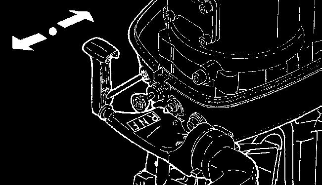
14 CONTROL FUNCTIONS Gear-shift lever. (Tiller handle versions) Starting out from the position of neutral gear ( N ), turn the lever in boat direction and you engage the clutch with the forward gear. Turning it in the opposite direction, you engage the reverse gear (R). Picture No. 20. Push-button to stop the motor. (Tiller handle versions) Pressing the stop button (red) the ignition circuit is broken and the engine stops immediately. Picture No. 21. Choke knob. (Tiller handle versions) Pulling out this knob provides a richer mixture which is required to start a cold engine. Picture No. 22. Fuel cock. (Integrated tank) (Versions: Oyster 6HP, Black Bass 8HP) Turning the cock you open or close the fuel connection to the carburator. Picture No. 23. Fuel joint. (Separated tank) (Tiller handle versions) Connecting the fast fuel joint, you connect the fuel hose to the fuel tank. Picture No. 24. Recoil starter handle. (Model with manual start) (Tiller handle versions) Pulling this handle starts the engine. Picture No. 25. Start button. (Model with electric start) (Tiller handle versions) Starting engine switch. Picture No. 26. Emergency engine stop switch. (Tiller handle versions) Switch to stop the engine in an emergency. Picture No. 27. Throttle-control adjustment. (Tiller handle versions) A device that allows the throttle to be fixed to give a constant speed. Picture No. 28. Accelerator-grip/steering-handle. (Tiller handle versions) Turn the grip to operate the accelerator, and move it sideways to adjust the steering angle. Picture No. 29. Cowling lock hook. (Tiller handle versions) Cowling locking device. To remove the top cowling pull the lever upwards. When replacing the cowl, ensure that it is correctly fitted over the tray and that the front hook is inserted correctly, locate the rear locking lever over the cowl s hook and push down to lock in place. Picture No
15 Free-lock lever to control the tilting arrangement. (Versions: Oyster 6HP, Black Bass 8HP) This lever controls/locks the engine s tilting hook assembly to prevent the engine tilting when in reverse gear due to the propeller thrust. Picture No. 31. Clamp-screws. (Versions: Oyster 6HP, Black Bass 8HP) Use them to clamp the outboard motor on the transom. Picture No. 32. Steering adjustment grip. (Versions: Oyster 6HP, Black Bass 8HP) With it you can adjust the resistance to steering movement. Screw it to increase resistance. Picture No. 33. Shallow water lever. (Versions: Oyster 6HP, Black Bass 8HP) It s used to release the tilt support bar. Picture No. 34. Trim angle adjusting-rod. (Versions: Oyster 6HP, Black Bass 8HP) It can be positioned in different holes in order to obtain the appropriate trim angle. Picture No. 35. Free-lock lever to control the tilting arrangement. (Versions: BIG FOOT 6/8HP Piranha 9,9) This lever controls/locks the engine s tilting hook assembly to prevent the engine tilting when in reverse gear due to the propeller thrust. Picture No. 36. Clamp-screws. (Versions: BIG FOOT 6/8HP Piranha 9,9) Use them to clamp the outboard motor on the transom. Picture No. 37. Steering adjustment grip. (Versions: BIG FOOT 6/8HP Piranha 9,9) With it you can adjust the resistance to steering movement. Screw it to increase resistance. Picture No. 38. Tilt-up lever. (Versions: BIG FOOT 6/8HP Piranha 9,9) Using it you lock or unlock the motor in the tilted up position. Picture No. 39. Trim angle adjusting-rod. (Versions: BIG FOOT 6/8HP Piranha 9,9) It can be positioned in different holes in order to obtain the appropriate trim angle. Picture No
16 Wiring diagram Picture No. 41. Model with manual start Legend 1. Flywheel 2. Ignition-coil 3. Sparking plug. 4. Emergency engine stop switch / Stop button Wiring colour scheme Red = Re Black = Ba Blue = Bu Brown = Br Black / Light blue = Ba / Az Light blue = Az Grey = Gr Orange = Or White = Wh Wiring diagram Picture No. 42. Model with electric start Legend 1. Generator 2. Ignition-coil 3. Sparking plug. 4. Emergency engine stop switch / Stop button 5. Start button 6. Solenoid 7. Starter motor 8. Rectifier 9. Micro-switch 10. Starting bloc control cable 11. Battery SYMBOLS Picture No A serious risk is present. The machine operator must read and follow the instructions in the manual. 2. Pull the choke knob. 3. Position of the gear-shift lever. 4. Outboard motor free lock. 5. Opening level of the throttle. 6. Warning against fire hazard. 7. Starter-switch for engine. 8. Button to stop the motor. 9. Indication fuel cock positionning. 10. Electric starting button. (Mod. with electric start) 15
17 THE USE OF OUTBOARD MOTOR PRELIMINARY CONTROLS CHART DETAIL CHECK DESCRIPTION PAGE Complete supply Check that the motor supply includes all the components, that are in the detailed list. 16 Check the proper installation of your motor (the centre of the transom). 16 Right installation Check the proper mounting height of your motor. 16 Check the tightness of the clamp screws. 16 Check the conformity of the fuel to the detailed list. 19 Fuel hose connection Check the proper connection of the fuel hose. 19 Oil filling Check the motor oil level in the oil sump with the appropriate dipstick 27 Battery and fuel tank Check the position of the battery and fuel tank from detailed list Check of the equipment on board Check that you have on board everything necessary to face a possible emergency. Before leaving always check your motor to make sure that it is in a perfect state of efficiency, check its proper and safe functionality. Failure to check as shown in the chart could result in severe injury to people or damage to the boat. If you ever have a question about the operation of your outboard motor, or if you should find any kind of anomaly, please consult a SELVA MARINE dealer. The time which is needed to check your motor is very modest, but the safety, that you obtain from it is enormous 16
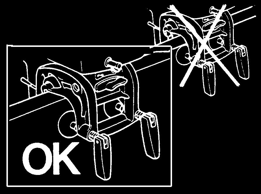
18 CHECK OF THE SUPPLY c OUTBOARD MOTOR MOUNTING When you receive your motor, check that: - the packing is integral - the supply corresponds to the detailed list: 1. The entire motor. 2. Remote control box (only for remote control box version) 3. Fuel tank supplied complete with the fuel hose and fast fuel joint ( for the motors with separate fuel tank ). 4. Tool-bag. 5. Use and maintenance manual. 6. Certificate of guarantee. 7. Declaration of conformity E.E.C. - Check that there is no evidence of damage. If there is any damage or if parts are missing, you must inform immediately and in detail the forwarding- agent, SELVA joint-stock CO. or its area agents. Picture No. 44. A good position of the motor on the transom is very important to have an appropriate trim angle and therefore to obtain a good performance from your boat To have the optimum mounting height of the outboard motor, you must mount it so that the anticavitation plate is between the bottom of the boat and a level of 2 cm below it and it is parallel to it. If the mounting-height is too high, cavitation tends to occur and consequently there will be a falling-off in the performance and a probable overheating of the motor. If the mounting-height is too low, the waterresistance will increase and thereby reduce engine efficiency. Picture No. 45. The motor must be vertical to the water surface and the bracket mounted on a flat even surface and should be fully supported by the top edge of the transom. If the bracket is not fully supported or, if the transom height is too low, a hard wood block should be securely fitted between the bracket and the transom. (Versions: Oyster 6HP, Black Bass 8HP) Picture No. 46. (Versions: BIG FOOT 6/8HP Piranha 9,9) Picture No
19 REMOTE CONTROL BOX INSTALLATION c To install the remote control box and the cables we suggest you contact an official dealer SELVA MARINE. We suggest you contact this dealer also for the control device installation. Never bind or entangle the cables of the remote control box. They mustn't be bound with a bending ray inferior to 300 mm. (12 feet). The cables must be of the type C-8. An improper installation of a remote control box may cause a sudden and unexpected loss of control, of the boat. In case or doubts about the remote control installation, ask your SELVA MARINE dealer. Position of the remote control box Normally the remote control box is supplied to be in positioned on the right. If you need to have it on the opposite side, ask your dealer. When positioning the remote control box pay attention that the control lever can be gripped and operated comfortably and without obstacles. Even the cables must be put in order not to have any obstacle on their patch and must not get in the way of the passengers. Be sure that the cables are long enough and that they can't get entangled when the steering-wheel is operating. Picture No. 48 CONNECTION OF THE CABLES OF CONTROL To connect the remote control cables please use the K50 kit (supplied with the motor) which is composed by: Na. 4 Cable end connections Na. 2 Sheath retainer support Na. 4 Screw TC Phillips M5x14 Na. 2 Clips Na. 2 Grower washer M5 Na. 2 Seeger rings Na. 3 Screw TSPTC M6x100 Na. 3 Washer M6 Na. 3 Selflocking nut M6 If the cables aren't correctly installed, they can get entangled causing the loss of control of the boat. 18
20 Side of the remote control box To connect the control cables to the box you have to follow the following instructions: Remove the lower cover (6) of the remote control box by unscrewing the two screws. Put the control lever (1) in neutral position. Screw completely the gear to connect the remote control box (9) to the threaded extremity of the cables and fix them with the counter-nut, paying attention not to tighten it too much. Put the head of the gear-control lever in the pawl of the gear lever (10) and insert the retaining ring (8). Insert the head of the gas-control cable in the pawl of the accelerator lever (11) and insert the retaining ring. Fix the sheathing of the cables inserting the sheathingretainer in its housing. c Insert the cables in the tray, letting them pass through the holes made on the right side of the fuel connector. Screw the remote control heads at the end of the two cables. Insert the heads in the pawls of the gears and accelerator levers, paying attention not to muddle the cables. Screw the lower cover. Picture No. 49 Remote control box fixation After having connected the remote control cables, put the box in the foreseen position and fix it with the screws. Picture No.50 Connection from the side of the motor Fix the sheath of the accelerator control cable putting the sheath retainer in correspondence of the groove of the sheath and screwing it (using the two screws TC Phillips M5x14 and the two self-locking nuts of the K 50 kit) in the holes made on the support of the remote control box sheath retainers, side A. Fix the heads on the pawls using the clips Make again the same operation for the gears control cable screwing the bolt in correspondence of the holes made on the support, side B. The sheath retainer support must be fixed in two different positions according to the length of the control cables. Another adjustment can be made unscrewing the remote control box heads. When you've finished the adjustment fix the heads with the counter nuts. Picture No. 51 To connect the control cables to the motor follow the following instructions: Put the remote control lever in the neutral position. Lower completely the gas control lever in neutral position 19 Control at the end of the operations the correct functioning of the remote control box.
21 STEERING CONTROL DEVICE MOUNTING c The steering control device is not supplied with the engine and can be different on depending from the boat type. For the mounting instructions, please refer to the installation manual of the steering control kit. BATTERY MOUNTING Connecting the battery Before connecting or disconnecting the battery leads remove the emergency cut-off, to avoid risks of electric shock, fire or explosion. It is important to install with the battery the battery disconnect switch. (not included) Mount the battery in a dry, well-ventilated, vibrationfree location in the boat. Recommended battery type: 12V 40 AH (144 kc) Connect the red lead to the positive terminal (+) first; then connect the black lead to the negative terminal (-). 1. Red lead 2. Black lead 3. Battery 4. Battery disconnect switch Picture No. 52. To disconnect the battery, disconnect the black lead first. 20 It is important to disconnect the battery connection with the battery disconnect switch only when the engine is stopped. The disconnection of the battery when the engine is running can make serious damages to the engine. Battery electrolytic fluid is dangerous; it contains dilute sulphuric acid and therefore is poisonous and highly caustic Always follow these preventive measures: - Avoid bodily contact with electrolytic fluid as it can cause severe burns or permanent eye injury. - Wear protective eye gear when handling or working near batteries. - If any battery electrolytic fluid spills onto your skin, flush with water. - If you should get battery electrolytic fluid in your eyes flush with water for 15 minutes and get immediate medical attention. - If you should swallow battery electrolytic fluid, drink large quantities of water or milk followed by milk of magnesia, beaten eggs or vegetable oil. Get immediate medical attention. Batteries also generate explosive hydrogen gas. Therefore avoid operating in areas which are not well-ventilated or near fire, spark, or open flames. DO NOT SMOKE when charging or handling batteries. KEEP BATTERIES AND ELECTROLYTIC FLUID OUT OF REACH OF CHILDREN.
22 TRIM ANGLE ADJUSTING The trim angle is the inclination angle, that should be given to the motor in order to obtain an optimal performance from your boat. An improper trim angle does not only affect the performance of your boat, but can also cause loss of control, which means danger for the people on board. While sailing the motor should be perpendicular to the water surface, but the trim angle can be 3 degrees to 5 degrees. If the trim angle is made too great, the buoyancy centre of the boat will shift towards the stern. In this condition, and if the stability moment at the bow is large, the boat will tend to "porpoise". If the trim angle is insufficient, the bow may "plough", making the boat unstable. When the boat is in stable trim it remains parallel to the water. To adjust the trim angle proceed as follows: (Versions: Oyster 6HP, Black Bass 8HP) - close the safety valve of the fuel tank (for motors with built in fuel tank ); - push down the free-lock lever and tilt up the motor ; - remove the adjusting-rod and reposition the rod in the desired hole, which allows the appropriate trim angle; - unlock the tilt support bar and bring again the motor in the vertical position, so that it leans on the adjustment pin; c 21 - set the free-lock lever to the lock position. To adjust the trim angle proceed as follows: (Version: Black Bass BIG FOOT 8HP) - push down the free-lock lever and tilt up the motor till first automatic stop; - lock the motor in the tilted up position,pushing down the tilt-up lever; - remove the adjusting-rod and reposition the rod in the desired hole, which allows the appropriate trim angle; - slightly tilt up the motor, unlock the tilt up lever, pushing it upwards and bring the motor back to the vertical position, so that it leans on the adjustment pin; - set the free-lock lever to the lock position. Improperly distributed load on boat or in different positions, can alter the ideal trim conditions. You must adjust the trim angle when the engine is switched off. (Versions: Oyster 6HP, Black Bass 8HP) Picture No. 53. (Versions: BIG FOOT 6/8HP Piranha 9,9) Picture No. 54. Ensure the transom clamp screws are tightened securely (Versions: Oyster 6HP, Black Bass 8HP) Picture No. 55. (Versions: BIG FOOT 6/8HP Piranha 9,9) Picture No. 56.
23 FUEL c Preparation of the fuel Fuel The fuel used for the propulsion of internal combustion engines is highly flammable and, in certain cases can become explosive. Refuelling and maintenance operations must be done in a well-ventilated area and with the engine stopped. Do not smoke while refuelling, keep away from sparks, flames, or other sources of ignition, which could cause fire or explosion. Do not spill gasoline. If gasoline spills, wipe it immediately with dry rags, before starting the motor. Do not overfill the fuel tank, because gasoline expands with the heat and the sun radiation. Tighten the filler cap securely after refuelling. Do not let gasoline get into your eyes or onto your skin. Avoid swallowing gasoline or inhaling its vapour. Use only petrol with a octane number higher than 95 N.O. Research and that they not contain alcohol. (see the detailed list) Fuel tank clamping and pipes connection Put the fuel tank horizontally in the hull, anchored to the bottom, in a place where it does not hinder your movements and so that the piping is long enough to reach the motor. Then connect the piping to the fuel joint. Picture No. 57. For this operation you have to insert the female fast fuel joint. Picture No. 58. Now you have to check the connection, pulling lightly the joint (do not pull grasping the hose). Picture No. 59. To release it is enough to pull the ring nut of the fast joint. Do not pour fuel off using a pipe. KEEP OUT OF CHILDREN REACH 22
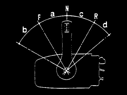
24 USE OF THE REMOTE CONTROL BOX Leaving from the position N of the control lever, to position in forward gear you have to lift the retainer lever and to put the control lever in position F. The insertion of the gear is indicated by a release of the movement. if the lever goes on in its travel, the accelerator begins to operate. At the end of the travel of the lever there is the maximum opening of the throttle valve. To select the reverse gear you have to put the control lever in position R. If, when the gear is selected, the lever goes on in its travel, the acceleration phase begins N F R a b c d Neutral position (neutral) Forward gear (forward) Reverse gear (reverse) Travel to select the forward gear Acceleration travel if forward gear is selected Travel to select reverse gear Acceleration travel if reverse gear is selected Picture No. 60 c Accelerating when neutral gear is selected To open the throttle when the neutral gear is selected (gear lever in N position), you have to use the neutral gear lever and turn it up. Picture No. 61 Before selecting the gear you always have to put the gas lever at the neutral position, in repose position (completely down). The gas lever can be actionned only when the control lever is in position N. The control lever can be actionned only when the gas neural control lever is at repose position (completely down). The micro switch prevents the motor from starting when the gear is selected. The travel of the acceleration when the reverse gear is selected is mechanically limited on the motor. To avoid damages not to force on the control lever. 23
25 STARTING c Starting procedures for motors with separatated fuel tank (Model with manual start): Verifications before starting the motor Check that the top cowling is locked, that the freelock mechanism is in the lock position and that the gear-shift lever is in the neutral position ( N ). Picture No. 62. Make sure that the lanyard s lock plate is installed on the engine stop switch. Picture No. 63. Start-in-gear protection device This feature permits the engine to be started only when it is in Neutral. Starting procedures for motors with built in fuel tank (Model with manual start): 1. Open the fuel cock. If the engine is cold, pull out the choke knob. Picture No Place the throttle-grip in the "start" position. Picture No Pull the starter-handle slowly so that the starter pinion engages with the flywheel. Picture No Set the choke knob to home position. Picture No Pull the starter-handle powerfully until the engine starts. If necessary, repeat the procedure. Picture No Loosen the air vent valve on the fuel tank filler cap. Picture No Fill up the carburettor with fuel using the priming bulb in the fuel line. Keep pressing the priming bulb until it becomes firm. If the engine is cold, pull out the choke knob. Picture No Place the throttle-grip in the "start" position. Picture No Pull the starter-handle slowly so that the starter pinion engages with the flywheel. Picture No Set the choke knob to home position. Picture No Pull the starter-handle powerfully until the engine starts. If necessary, repeat the procedure. Picture No. 70. Starting procedures for motors with separatated fuel tank (Model with electrical start) 1. Loosen the air vent valve on the fuel tank filler cap. Picture No Fill up the carburettor with fuel using the priming bulb in the fuel line. Keep pressing the priming bulb until it becomes firm. If the engine is cold, pull out the choke knob. Picture No Place the throttle-grip in the "start" position. Picture No Push the start switch for a maximum of 5 second. Picture No
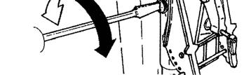
26 5. Immediately when the engine starts, release the start switch. Picture No Set the choke knob to home position. Picture No. 69. c Verifications when the motor is on Just after starting the motor, you should make sure that : Starting procedure (Model with electrical start with remote control box) Loose the safety valve on the fuel tank. Picture No. 65. Using the hand-pump fill up the carburettor tank with the fuel (When the pump is hard, it means that you've achieved your aim). Place the control lever in the neutral position. Lift lightly the gas control in neutral lever. Push towards the high the choke lever. Turn the starting key till the start position, keeping it into this position not more than 5 seconds. When the motor starts release the key (that will be in position ON), the choke lever and the gas control in neutral lever. Picture No. 73. ATTENTION You don't need to use the choke-knob, if the engine is warm. If the motor doesn't start after several attempts, you should refer to the troubleshooting section. When restarting an integral tank model, which has stopped because it has run out of fuel, after refuelling, even with a warm motor, we suggest the choke knob is pulled out, as this will ease refilling of the carburettor after 5/10 seconds, water runs out from the coolingwater pilot-holes. Picture No. 74. The indicator at the entrance of the circuit, provides only for the proper operation of the pump and not for the circulation of water in the head and in the cylinder. That means that possible shortages will not be indicated. If water does not flow from the pilot-holes check to see if the water-inlets are blocked - that you do not hear any strange noise; - that the throttle-grip operates in a proper way; - that the gear shift lever operates properly and that with the reverse gear selected the motor does not rise; - that the engine stop switch operates properly.
27 Emergency starting procedures c RUNNING-IN PROCEDURE If the starter does not operate, the engine may be started with an emergency starter rope. Carry out the following operations: Remove the cowling; place the gear-shift lever in the neutral position N ", and the throttle-grip in the start position and check the installation of the lock-plate on the engine stop switch. Remove the screws blocking the starter and removing it (it is necessary to detach the block start system with inserted gear) Insert the knotted end of the emergency starter rope into the notch in the flywheel rotor, wind the rope two turns clockwise, and then pull strongly to start. Repeat if necessary. When starting the engine with the emergency starter rope, it is very important to make sure that nothing can get entangled in the engine. A rotating flywheel is very dangerous. never try to replace the top cowling when the engine is running. Proceed at once to the nearest port to get the engine repaired. Take care to prevent water splashing onto the flywheel. A SELVA outboard motor is tested completely in our workshop and it is partially run in a tank. A second test is done by the concessionaire It is always advisable to complete the running in procedure in the following way:. During the first hour let the motor run at 2000 rpm maximum (or at half acceleration). During the second hour maintain it at 3000 rpm and accellerate at max speed for 1 minute max each 10 min. After this operation use the motor in a normal way. After 10 hours change the motor oil. After 20 hours change the gear oil (see the lubrification paragraph). A good running in will allow you to obtain a good performance from your motor and a longer endurance of it. While the emergency start, the starter block with inserted gear is disabled. Before to start the engine, make sure that the invester is in postition N. 26
28 c CRUISING Responsibility during the navigation. The operator is responsible for the proper running of the boat and for the safety of the people on board. Everybody must read this manual before cruising. Show all the passengers the location of the safety equipment and the way to use it. Teach one of your passengers, how to pilot the boating an emergency. Familiarise yourself with the laws and regulations in force where you want to sail. Shallow water cruising (Versions: Oyster 6HP, Black Bass 8HP) Picture No. 75. A SELVA motor is equipped with device, which adjusts the trim angle so that you can sail in shallow water. This operation must be carried out with the engine not in motion and paying very much attention. Cruising in shallows, run the boat at the lowest possible speed. To bring the engine to the home position: - Tilt up slightly the engine (using always the proper handle); - Release the tilt support bar, operating the shallow water levers and take the motor again to its vertical position; - Then set the free lock lever to the lock position. Tilt-up the motor (Versions: BIG FOOT 6/8HP Piranha 9,9) Picture No.76. To tilt up the motor do as follows: - Switch off the engine; - Unlock the free-lock lever; - Tilt the engine up using the proper handle; - Push downwards the tilt-ut lever. To bring it back to the cruising position: - You just have tilt up slightly the engine; - Unlock the tilt-up lever pushing it upwards; - Bring the motor back to the vertical position, so that it leans on the adjustment pin; - Set the free-lock lever to the lock position. - Release the free-lock lever; - Close the safety valve of the fuel tank (for motors with built in fuel tank); - Tilt up the engine till the first automatic stop using only the tilt up handle. 27
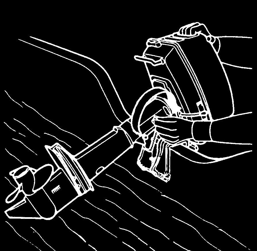
29 c STOPPING PROCEDURE Removal of the motor from the boat Emergency stopping procedures In an emergency you must stop your motor pulling the engine stop switch lanyard. To start the motor again you have to install again the lock plate on the engine stop switch. Picture No. 77. Stopping in normal conditions Place the gear-shift lever in the neutral position " N " (neutral gear); accelerate light in order to avoid floodings, run the engine again at idling speed and then push the stop button. (For tiller handle versions) Picture No. 78. Turn the switch key in the anti-clockwise direction (for remote control box versions). Picture No. 79. Stopping for a long period of storage If you don t use the motor for many days, is preferable to stop the engine in the following way: When engine is cold, take out the spark plugs and spray some c.c. of motor oil in the cylinder. To spread the oil internally gently pull the recoil starter to turn the motor over, re-install the spark plugs. 28 Each time that you remove the motor from your boat, you must let it cool down and then you have to do the following operations : - Close the fuel cock; - Disconnect the fast fuel joint; - Release the clamp screws; - Lift up the motor vertically and keep it in this position till all the water has run out from the cooling-water passages ( about 1 minute ) ; - Tilt up the steering rod; - Transport the motor using the proper handle; - Lay down the motor only in the specific position. Picture No. 80. If the engine is placed in the wrong position, oil from the sump may leak through the breather resulting in mechanical damage to the engine when used. Oil may come out from the engine.
30 CLEANING c lever into neutral. Start the engine and run at low speed for a few minutes. Cleaning outside SELVA motors do not need much cleaning, to clean the painted parts use a cloth soaked with water While cleaning the cooling water passages make sure that water always circulates in the passages, checking its running out of the pilot hole. Picture No. 81. Do not use flammable solvents. Cleaning cooling-water passages Every now and then after using, clean the cooling-water passages, in order to remove mud and salt, so that they do not affect the performance of your motor. You can carry out this cleaning operation in two different ways: 1. Immerse the outboard motor without the propeller in a vessel filled up with fresh-water, make sure that the water level is over the height of the water inlets, so that no irreparable damage could be caused to the motor. Shift the gear-shift lever into neutral " N ". Start the engine and run at low speed for a few minutes. 2. Connect a pipe of fresh-water to the hole for the engine cleaning joint plug ( use the proper joint available in the fittings series ). Stop the water inlets. Shift the gear-shift 29 MAINTENANCE Before doing any kind of maintenance or check operation, switch off the engine and wait till it has cooled down, then remove the spark plug cap, in order to avoid an accidental staring. Pay attention to the motor parts, which are still hot, so that you do not burn yourself. Some maintenance operations must be carried out by qualified staff. Contact SELVA MARINE after-sale service. The following chart lists the periodic maintenance operations to do on your motor. The pointed out operations must be done by qualified staff.
31 c PERIODIC INSPECTIONS AND ADJUSTMENTS OPERATIONS TO PERFORM (Running hours) Inspection of the conditions of the fuel hoses.if necessary replace them. Check the fuel hose joints for leaks If necessary replace them. Check the oil filter, if necessary replace it Check the proper working of the carburettor. If necessary adjust it. Check, clean and adjust the spark-plugs. If necessary replace them. Check the ignition. Check the head screws and the adjustment to the correct torque. Check the valve clearence Check the trasmission belt. If necessary replace it Check the efficiency of the water pump and of the cooling system Check the motor oil level Check the gearbox-oil level Check the wear of the anode. If necessary replace it. Check the condition of the propeller. If necessary replace it. THEREAFTER INITIAL EVERY Out of season 30 GREASE POINTS Motor block Gearbox Bushes of the clamps pipe Cowling lock levers pins Tie rod carburettor levers Propeller shaft Clamp screws GREASING CHART LUBRICANT THAT MUST BE USED API SE, SF, SG, SH SAE 10W-30 10W-40 15W-40 API GL-5 SAE 80 W 90 MIL -L 2105 C GREASING FREQUENCY FRESH-WATER SALT WATER Check the oil level every 6 months. If necessary add till the marked point. Change the oil after the first 10 running hours; afterwards every 100 hours, anyway change the oil once per season Check the level after the first 10 running hours. Afterwards every 50 hours. If necessary add till the marked point. Change the gearbox-oil after the first 20 running hours and afterwards every 100 running hours; and anyway each season. SPRAY LUBRICANT 60 days 30 days SPRAY LUBRICANT 60 days 30 days WATER-REPELLENT MARINE GREASE WATER-REPELLENT MARINE GREASE WATER-REPELLENT MARINE GREASE 60 days 30 days 60 days 30 days 60 days 30 days Gear-shift lever SPRAY LUBRICANT 60 days 30 days
32 GREASING AND ADDITIONS Motor Oil This engine is equipped with a forced lubrification system on the head block. Selva deliver the engine with the oil sum empty. Please pay the maximum attention before to start the engine that the oil sum will be filled with the specific oil and in the specific quantity as indicated in the technical table. The user has to change the oil completely after the first 10 cruising hours. After this change the level has to be checked every 50 hours using the appropriate graded deapstick, which is insterted in the level plug and replace it every 100 hours anyway at least once per season. Motor oil change To change the Motor oil do as follow: - Keep the motor in vertical position ; - Place a container to collect the used oil under the drain-oil hole ; - Take out the oil-level plug and the oil drain-plug ; - Wait until the oil has drained completely (during this operation you must check, if water or other foreign bodies are to be found in the drained oil. They are signs of anomalies which must be identified and repaired by qualified staff, before using the motor again) ; - Insert the oil drain plug and check the seal ; c 31 - Throught the filling hole fill the oil. The oil must agree with the characteristics listed in the greasing chart, and must comply with the quantity pointed out in the technical detailed list. Insert and tighten the oil-level plug and the oil drain plug. Picture No. 82. Gearbox-oil Selva supply the motor already with the oil in the gearbox, which the user will have to change completely after the first 20 cruising hours After this change you must check its level every 50 hours and change it every 100 hours, and anyway each season. Gearbox-oil change To change the oil do as follows: - Keep the motor in vertical position. - Place a container to collect the used oil under the gearbox. - Take out the oil-level plug and the oil drain-plug. They have a different size and after the oil change they must be replaced in their proper seat. - Wait until the oil has drained completely, (during this operation you must check, if water or other foreign bodies are to be found in the drained oil. They are signs of anomalies which must be identified and repaired by qualified staff, before using the motor again). - Protecting the leaning parts, put the motor horizontally, with the oil-level plug and the oil drain-plug holes upwards. - Inject the oil into the oil drain-plug hole. The oil must agree with the characteristics listed in the greasing chart, and must comply with the quantity pointed out in the technical detailed list. Insert and tighten the oil-level plug and the oil drain plug. (Versions: Oyster 6HP, Black Bass 8HP) Picture No. 83.
33 (Versions: BIG FOOT 6/8HP Piranha 9,9) Picture No. 84. Motor oil filter replacement The motor is equipped with a filter placed in the lubrication lead. The occlusion of the filter could compromise the fonctionemment of the engine and compromise seriously the efficiency. To replace the filter, motor must be switch off and without oil. Unscrew the filter and replace it with a new one. Picture No. 85. Spark-plug The used oil and the used filter oil (contain exaust oil) must be given to the proper collecting centres or to a SELVA service point. The spark-plug must be often inspected because heat and deposits affect its efficiency so that the performance of the motor will be affected too. The inspection of the spark-plug must be done when the engine is not running and it has cooled down. It is very important to check, that the part made of porcelain is not damaged because this could allow c 32 external sparks, which could lead to explosion or fire. To remove the spark-plug use the supplied spanner; using an abrasive brush, remove any deposits, then check the wear condition and the spark-plug gap ( the gap must be 0,6 mm, to measure it use a thickness gauge ). If the spark-plug is too badly worn you must replace it with a new one which must agree with the characteristics listed in the specifications chart. The spark-plug torque is 20 Nm ( ~ 2. kgm). If a torque-wrench is not available, you can obtain a good estimate of the correct torque turning the sparkplug completely by hand and then turning it with the spanner, a new spark-plug must be turned ~ 90 and an old one Replace the spark-plug cap, checking that it is correctly fitted and then replace the top cowling. Picture No. 86. Sacrificial anode. To protect the motor against electrochemical corrosion, due to the presence in its structure of many different materials, a sacrificial anode has been applied. The anode will be subject to a strong corrosion, so you have to remove the scales from the surfaces of the anode periodically. Failure to clean it, will affect its effectiveness. Do not paint the anode, for this would render it ineffective. When the corrosion compromise its functionality, you have to replace it.
34 (Versions: Oyster 6HP, Black Bass 8HP) Picture No. 87. (Versions: BIG FOOT 6/8HP Piranha 9,9) Picture No. 88. Replacement of the propeller. The propeller is one of the components, which have a great influence upon the performance of the motor. An unsuitable or damaged propeller can cause serious damages to the motor besides reduce the performance. c - Insert a wooden lump between the propeller blades and the anti-cavitation plate ; - Keep the propeller pressed against the pin and screw tight the nut. Picture No. 89. Storage For a careful choice of the propeller consult a SELVA MARINE service point. To replace the propeller do as follows: - Wait until the motor has cooled down and remove the top cowling ; - Remove the spark-plug cap, to avoid an accidental start during the operations of replacement of the propeller ; - Place the gear-shift lever in the neutral position "N" ; - Protect your hands using strong gloves and insert a wooden lump between the propeller blades and the anticavitation plate, to keep the propeller still ; - Remove the self stopping nut, the washer and the propeller ; - Spread the propeller shaft with water-repellent grease ; - Make sure, that the drive propeller pin is centred on the shaft; - By hand insert the propeller making sure that it gets correctly into the drive pin ; - Insert the washer and by hand screw the self-locking nut ; 33 To help the endurance of your motor, you must carry out properly the following storage operations: - Clean the motor and the cooling-water passages ; - Switch off the engine as shown in the section "stopping for a long period of storage " ; - Remove the fuel-line connections from the motor ; - Empty the float chamber ; - Change the motor oil ; - Change the gearbox-oil ; - Verify the valve clearence ; - Verify the correct timing ; - Check the screws torque ; - Grease all the components as shown in the greasing chart ; - Inspect the anode ; - Empty the fuel tank ; - Store the motor in the vertical position and in a dry, not to cold place. The storage operations must be carried out by qualified staff.
35 TROUBLESHOOTING,oo' A B C D E F G H I Possible cause A regular maintenance can help you prevent many problems with your outboard motor. The following chart lists some common difficulties and their possible causes. Fuel tank is empty Fuel hose is incorrectly connected Fuel hose is flattened or kinked Fuel pump is malfunctioning If you still have difficulties, after investigating these, please contact your SELVA MARINE dealer. A. The engine will not start. B. The engine runs irregularly or stails. C. The engine idles unevenly. D. Engine speed will not increase. E. The engine is overheating. F. Engine speed is higher than normal. G. Engine speed is lower than normal. H. Boat speed is too low. I. IThe boat will suddenly slow. J. The starter-motor does not operate (Model with electric start) Improper fuel Improper motor oil Carburettor has a wrong adjustment Wrong timing Incorrect starting procedure Sparks -plugs are fouled. Improper spark-plugs Incorrect spark-plug gap. Spark-plug cap incorrectly fitted 34
36 ,oo' A B C D E F G H I Possible cause A B C D E F G H I L Possible cause Electric circuit is defective Starter-motor is defective Ignition-coil is defective Start push button is defective Clogged water passages Battery is undercharged Faulty water-pump Thermostat faulty Cavitation is occurring Propeller is damaged Propeller has not the proper dimensions Incorrect trim-angle Load on boat is improperly distributed Transom is too high Transom is too low 35
37
38 15 16
39 A B C D E F G H I L M N O P Q R S T C L XL


40


41


42


43


44


45
46


47


48
OWER'S MANUAL. Corse
 OWER'S MANUAL Corse This manual must be considered as an integral part of your outboard motor and has to be kept with it, also if the motor is resold. Selva joint-stock CO. reserve the right to change
Zadar - Capri OWER'S MANUAL Zadar - Capri
 OWER'S MANUAL Zadar - Capri This manual must be considered as an integral part of your outboard motor and has to be kept with it, also if the motor is resold. Selva joint-stock CO. reserve the right to
OWNER'S MANUAL. Oyster 5 Oyster 6 Black Bass 7,5 Black Bass "BIG FOOT" 8
 OWNER'S MANUAL Oyster 5 Oyster 6 Black Bass 7,5 Black Bass "BIG FOOT" 8 Vers.02-2006 This manual must be considered as an integral part of your outboard motor and has to be kept with it, also if the motor
OWNER'S MANUAL. Antibes Maiorca
 OWNER'S MANUAL Antibes Maiorca This manual must be considered as an integral part of your outboard motor and has to be kept with it, also if the motor is resold. Selva joint-stock CO. reserve the right
OWNER'S MANUAL. Madeira St. Tropez Portofino Montecarlo
 OWNER'S MANUAL Madeira St. Tropez Portofino Montecarlo This manual must be considered as an integral part of your outboard motor and has to be kept with it, also if the motor is resold. Selva joint-stock
OWNER'S MANUAL. Bull Shark 40xs Bull Shark 50 Tiger Shark 80
 OWNER'S MANUAL Bull Shark 40xs Bull Shark 50 Tiger Shark 80 This manual must be considered as an integral part of your outboard motor and has to be kept with it, also if the motor is resold. Selva joint-stock
AIR-COOLED DIESEL GENERATOR OWNERʼS MANUAL. This manual contains important safety information. TDG2500E TDGW7000E TDG7000SE TDG4500E
 AIR-COOLED DIESEL GENERATOR OWNERʼS MANUAL This manual contains important safety information. TDG2500E TDGW7000E TDG7000SE TDG4500E TDG8000-3 TDG7000SE-3 TDG7000E TDG8000E TDGW7000SE TDG7000E3 TDGW8000E
SUZHOU PARSUN POWER MACHINE CO., LTD.
 OUTBOARD MOTOR OWNER S MANUAL T3.6BM (T2.5BM) SUZHOU PARSUN POWER MACHINE CO., LTD. Thank you for owning a PARSUN outboard motor. Thank you for your trust in our company and products. PARSUN outboard motors
SUZHOU PARSUN POWER MACHINE CO., LTD.
 OUTBOARD MOTOR OWNER S MANUAL T15BM (T9.9BM) SUZHOU PARSUN POWER MACHINE CO., LTD. Thank you for owning a PARSUN outboard motor. Thank you for your trust in our company and products. PARSUN outboard motors
Light condition and operation Windshield glass condition Wiper blade condition Paint condition and corrosion Fluid leaks Door and hood lock condition
 GENERAL CHECKS Engine Compartment The following should be checked regularly: Engine oil level and condition Transmission fluid level and condition Brake fluid level Clutch fluid level Engine coolant level
1100W PORTABLE GENERATOR
 1100W PORTABLE GENERATOR MODEL NO: G1200 PART NO: 8010110 OPERATION & MAINTENANCE INSTRUCTIONS LS0312 INTRODUCTION Thank you for purchasing this CLARKE 1100W Portable Generator. Before attempting to use
Electric Trolling Motor
 Electric Trolling Motor L Series User s Manual Please read and retain this manual before using product REACH RoHS TABLE OF CONTENTS Contents GENERAL INFORMATION 4 SPECIFICATIONS 4 WIRING AND BATTERY RECOMMENDATIONS
IMPORTANT INFORMATION
 Table of Contents IMPORTANT INFORMATION Section 1B - Maintenance MAINTENANCE 1 B Specifications................................ 1B-1 Special Tools................................ 1B-2 Quicksilver Lubricant/Sealant..................
FORZA BOLT OUTBOARD MOTOR OWNER S MANUAL
 FORZA BOLT OUTBOARD MOTOR OWNER S MANUAL Table Of Contents 1.Introduction...1 2.Safety Information.1 3.Refuelling Information...1 4.Safety Matters 2 5.Preparation.3 6.Operation.3 7.Maintenance...4 8.Storage...5
1200W INVERTER GENERATOR
 1200W INVERTER GENERATOR MODEL NO: IG1200 PART NO: 8877070 OPERATION & MAINTENANCE INSTRUCTIONS LS0117 INTRODUCTION Thank you for purchasing this CLARKE 1200W Inverter Generator. Before attempting to use
OUTBOARD MOTOR OWNER S MANUAL F6ABM F5ABM SUZHOU PARSUN POWER MACHINE CO., LTD.
 OUTBOARD MOTOR OWNER S MANUAL F6ABM F5ABM SUZHOU PARSUN POWER MACHINE CO., LTD. Thank you for owning a PARSUN outboard motor. Thank you for your trust in our company and products. PARSUN outboard motors
BF25D BF30D Owner s Manual
 BF25D BF30D Owner s Manual 2004 Honda Motor Co., Ltd. -All Rights Reserved 2005 The engine exhaust from this product contains chemicals known to the State of California to cause cancer, birth defects,
OUTBOARD MOTOR OWNER S MANUAL F4BM (F5BM) SUZHOU PARSUN POWER MACHINE CO., LTD
 SUZHOU PARSUN POWER MACHINE CO., LTD") OUTBOARD MOTOR OWNER S MANUAL F4BM (F5BM) SUZHOU PARSUN POWER MACHINE CO., LTD Thank you for owning a PARSUN outboard motor. Thank you for your trust in our company and products. PARSUN outboard motors
OUTBOARD MOTOR OWNER S MANUAL F4BM (F5BM) SUZHOU PARSUN POWER MACHINE CO., LTD Thank you for owning a PARSUN outboard motor. Thank you for your trust in our company and products. PARSUN outboard motors
Gasoline Inverter Generator
 user manual Gasoline Inverter Generator table of contents Preface Introduction... Safety Information Exhaust fumes are poisonous... Fuel is highly flammable and poisonous... Engine and muffler may be hot...
Parsun Portable 4-Stroke Outboard Motor Winterize or Storing DIY Service Guide
 Parsun Portable 4-Stroke Outboard Motor Winterize or Storing DIY Service Guide To help keep your engine in tip-top condition for years to come, it is important that you winterize your outboard for off-season
5.5KVA GENERATOR MODEL NO: PG6500DVES OPERATION & MAINTENANCE INSTRUCTIONS PART NO: LS0616
 5.5KVA GENERATOR MODEL NO: PG6500DVES PART NO: 8857810 OPERATION & MAINTENANCE INSTRUCTIONS LS0616 INTRODUCTION Thank you for purchasing this CLARKE 5.5KVA Generator. Before attempting to use this product,
HOT WASHER MODEL NO: KING 125 OPERATION & MAINTENANCE INSTRUCTIONS PART NO: LS1009
 HOT WASHER MODEL NO: KING 125 PART NO: 7320170 OPERATION & MAINTENANCE INSTRUCTIONS LS1009 INTRODUCTION Thank you for purchasing this Hot Washer. This machine is a portable, high pressure power washer,
Operation Manual. 21 Inch Self-Propelled Lawn Mower MODEL #
 21 Inch Self-Propelled Lawn Mower MODEL # 106461 Operation Manual This safety alert symbol identifies important safety messages in this manual. Failure to follow this important safety information may result
LDG6000SA DIESEL GENERATOR OWNERS MANUAL
 LDG6000SA DIESEL GENERATOR OWNERS MANUAL BEFORE OPERATING THIS EQUIPMENT PLEASE READ THESE INSTRUCTIONS CAREFULLY Preface Thank-you for purchasing this generator. This operation manual contains information
OUTBOARD MOTORS OWNER S MANUAL F15A BM/BW/FW F20A BM/BW/FW SUZHOU PARSUN POWER MACHINE CO., LTD.
 OUTBOARD MOTORS OWNER S MANUAL F15A BM/BW/FW F20A BM/BW/FW SUZHOU PARSUN POWER MACHINE CO., LTD. Thank you for owning an outboard motor. Thank you for your trust in our company and products. The outboard
720W PORTABLE GENERATOR
 720W PORTABLE GENERATOR MODEL NO: G720 PART NO: 8857800 OPERATION & MAINTENANCE INSTRUCTIONS LS0214 INTRODUCTION Thank you for purchasing this CLARKE 720W Portable Generator Before attempting to use this
OWNER S MANUAL BFT 200A 225A
 OWNER S MANUAL BFT 200A 225A The engine exhaust from this product contains chemicals known to the State of California to cause cancer, birth defects, or other reproductive harm. Keep this Owner s Manual
The engine exhaust from this product contains chemicals known to the State of California to cause cancer, birth defects, or other reproductive harm.
 The engine exhaust from this product contains chemicals known to the State of California to cause cancer, birth defects, or other reproductive harm. Keep this owner s manual handy, so you can refer to
WARNING! Ensure that there are no naked flames around the product! Do not smoke while filling fuel and oil!
 Engine Oil and Fuel Engine Operation This product is equipped with a 4 stroke engine. Before operation you have to add proper fuel and engine oil. DO NOT MIXTURE THEM! 1. Place the product on a stable,
The engine exhaust from this product contains chemicals known to the State of California to cause cancer, birth defects, or other reproductive harm.
 C 2003 Honda Motor Co., Ltd. -All Rights Reserved 2004 The engine exhaust from this product contains chemicals known to the State of California to cause cancer, birth defects, or other reproductive harm.
OUTBOARD MOTOR OWNER S MANUAL F9.8BM F8BM F6BM SUZHOU PARSUN POWER MACHINE CO., LTD
 OUTBOARD MOTOR OWNER S MANUAL F9.8BM F8BM F6BM SUZHOU PARSUN POWER MACHINE CO., LTD Thank you for owning a PARSUN outboard motor. Thank you for your trust in our company and products. PARSUN outboard motors
IMPORTANT INFORMATION
 Table of Contents IMPORTANT INFORMATION Section 1B - Maintenance MAINTENANCE 1 B Specifications........................... 1B-1 Special Tools........................... 1B-2 Mercury/Quicksilver Lubricants
STIGA TORNADO 51 S 51 SE PRO 51 S
 STIGA TORNADO 51 S 51 SE PRO 51 S 8211-0225-09 SVENSKA S 1 2 3 1. 2. ADD FULL FULL ADD ADD FULL 0,15 l. 3. LS 45 4. XTE 60 3x 5. LS 45 6. XTE 60 STOP I H 7. 8. 2 S SVENSKA 9. 10. 11. 12. LS 45 0,75 mm
FORZA BOSS OUTBOARD MOTOR
 FORZA BOSS OUTBOARD MOTOR Table of Contents 1. Safety Information.....1 2. Product Features and Operation... 2 3. Technical Features and Specifications......6 4. Overall Dimensions...8 5. Installation..........8
OWNER S MANUAL BFT 75A 90A
 OWNER S MANUAL BFT 75A 90A The engine exhaust from this product contains chemicals known to the State of California to cause cancer, birth defects, or other reproductive harm. Keep this Owner s Manual
BF4A BF5D BF6A. Includes US and Canadian Models Honda Motor Co., Ltd. All Rights Reserved
 BF4A BF5D BF6A Includes US and Canadian Models 2017 Honda Motor Co., Ltd. All Rights Reserved The engine exhaust from this product contains chemicals known to the State of California to cause cancer, birth
The engine exhaust from this product contains chemicals known to the State of California to cause cancer, birth defects, or other reproductive harm.
 The engine exhaust from this product contains chemicals known to the State of California to cause cancer, birth defects, or other reproductive harm. Keep this owner s manual handy, so you can refer to
The engine exhaust from this product contains chemicals known to the State of California to cause cancer, birth defects, or other reproductive harm.
 The engine exhaust from this product contains chemicals known to the State of California to cause cancer, birth defects, or other reproductive harm. Keep this Owner s Manual handy, so you can refer to
MOTORINI GP 50. User s Manual.
 MOTORINI GP 50 User s Manual www.motorini.co.uk Dear user: Thank you for choosing to buy a Motorini GP 50 This manual provides the correct operation and maintenance methods for safe riding and maintaining
The engine exhaust from this product contains chemicals known to the State of California to cause cancer, birth defects, or other reproductive harm.
 The engine exhaust from this product contains chemicals known to the State of California to cause cancer, birth defects, or other reproductive harm. Keep this owner s manual handy, so you can refer to
GRAVELY CONVERTIBLE 10 CONVERTIBLE 12 OWNERS MANUAL
 A SAFETY MESSAGE The product for which you have requested information or replacement parts is not a current product. The replacement models incorporate product designs, safety features, safety instruction
Engine oil. Introduction. Warning and indicator lights WARNING
 Engine oil Introduction In this section you ll find information about: Warning and indicator lights Engine oil specifications Engine oil capacities Checking the engine oil level and adding oil Engine oil
Ciscomotors C-Max All types of models
 Ciscomotors C-Max All types of models SiMPLIFIED MAINTENANCE MANUAL All information in this publication is based on latest specification s product available at the time of approval for printing. CISCOMOTORS
GENERATOR MODEL NO: FG2500 OPERATION & MAINTENANCE INSTRUCTIONS PART NO: LS0114
 GENERATOR MODEL NO: FG2500 PART NO: 8857727 OPERATION & MAINTENANCE INSTRUCTIONS LS0114 INTRODUCTION Thank you for purchasing this CLARKE Generator. Before attempting to use this product, please read this
RedGum GP160 Splitter. Owner s Manual
 RedGum GP160 Splitter Owner s Manual Product Description & Intended Purpose: This Log Splitter / Wood Splitter is an outdoor product that splits wood logs for use as fuel in a fireplace or a woodstove.
GENERATOR MODEL NO: FG3000 OPERATION & MAINTENANCE INSTRUCTIONS PART NO: LS0609
 GENERATOR MODEL NO: FG3000 PART NO: 8857700 OPERATION & MAINTENANCE INSTRUCTIONS LS0609 INTRODUCTION Thank you for purchasing this CLARKE Generator. Before attempting to use this product, please read this
Changing light bulbs. Introduction WARNING
 Changing light bulbs Introduction In this section you ll find information about: Indicator light Information on light bulb replacement Changing headlight bulbs Changing the fog light bulbs in the front
OUTBOARD YEARS. warranty. FOR LEISURE USE ONLY Subject to terms and conditions see your Dealer for more information. Selva Marine F OLLOW US ON
 OUTBOARD YEARS warranty FOR LEISURE USE ONLY Subject to terms and conditions see your Dealer for more information F OLLOW US ON Selva Marine Outboard Motors OUTBOARD YEARS warranty FOR LEISURE USE ONLY
Disc Brake System ( For Cross-Country)
") Technical Service Instructions General Safety Information Disc Brake System ( For Cross-Country) SI-8C60F t WARNING Please use extra caution to keep your fingers away from the rotating disc brake rotor
Technical Service Instructions General Safety Information Disc Brake System ( For Cross-Country) SI-8C60F t WARNING Please use extra caution to keep your fingers away from the rotating disc brake rotor
Vehicle battery BATTERY WARNING SYMBOLS BATTERY CARE
 Vehicle battery BATTERY WARNING SYMBOLS On the battery label, the warning signs are as follows: BATTERY CARE No smoking, no naked flames, no sparks. The battery may emit explosive gas. Keep away from children
The engine exhaust from this product contains chemicals known to the State of California to cause cancer, birth defects, or other reproductive harm.
 The engine exhaust from this product contains chemicals known to the State of California to cause cancer, birth defects, or other reproductive harm. Keep this Owner s Manual handy, so you can refer to
English N Reference : Date : 12/2007 Version : A. This photograph does not necessarily represent the engine
 English N4.00 Reference : 970 34 343 Date : 2/2007 Version : A This photograph does not necessarily represent the engine N4.00 - Owner s manual Technical characteristics Engine specifications Cycle 4 strokes,
OWNER S MANUAL BFT 60A BFW 60A
 OWNER S MANUAL BFT 60A BFW 60A The engine exhaust from this product contains chemicals known to the State of California to cause cancer, birth defects, or other reproductive harm. Keep this Owner s Manual
3KVA DUAL VOLTAGE GENERATOR MODEL NO: PG3800DV
 3KVA DUAL VOLTAGE GENERATOR MODEL NO: PG3800DV PART NO: 8857815 OPERATION & MAINTENANCE INSTRUCTIONS LS1016 INTRODUCTION Thank you for purchasing this CLARKE 3KVA Dual Voltage Generator. Before attempting
YK1900i DIGITAL INVERTER GASOLINE GENERATOR OWNER S MANUAL PLEASE READ THIS MANUAL CAREFULLY. IT CONTAINS IMPORTANT SAFETY INFORMATION.
 YK1900i DIGITAL INVERTER GASOLINE GENERATOR OWNER S MANUAL PLEASE READ THIS MANUAL CAREFULLY. IT CONTAINS IMPORTANT SAFETY INFORMATION. PREFACE Thank you for purchasing YANGKE generator. This manual covers
 OWNERS MANUAL www.prodriveoutboards.com PO Box 949 129 S Main St. Loreauville, LA PH#: 337-229-0034 FAX#: 337-229-2302 1 TO THE OWNER Thank you for purchasing a Pro-Drive Shallow Water Outboard. Your unit
BF200A/BF225A Owner s Manual
 BF200A/BF225A Owner s Manual 2003 Honda Motor Co., Ltd. -All Rights Reserved 2004 The engine exhaust from this product contains chemicals known to the State of California to cause cancer, birth defects,
WARNING: Read these instructions before using the machine GENERATOR MODEL NO: IG3500F PART NO: OPERATION & MAINTENANCE INSTRUCTIONS
 WARNING: Read these instructions before using the machine GENERATOR MODEL NO: IG3500F PART NO: 8877100 OPERATION & MAINTENANCE INSTRUCTIONS ORIGINAL INSTRUCTIONS LS0217 INTRODUCTION Thank you for purchasing
OWNER S MANUAL BFT 250A
 OWNER S MANUAL BFT 250A OWNER S MANUAL BFT 250A Original instructions 2016 Honda Motor Co, Ltd PGM-FI is a trademark of Honda Motor Co, Ltd registered in Japan and other countries Thank you for purchasing
The engine exhaust from this product contains chemicals known to the State of California to cause cancer, birth defects, or other reproductive harm.
 The engine exhaust from this product contains chemicals known to the State of California to cause cancer, birth defects, or other reproductive harm. Keep this Owner s Manual handy, so you can refer to
ATV-50/90/100 I/II/V OWNER S MANUAL
 1 ATV-50/90/100 I/II/V OWNER S MANUAL FOREWORD May we, the manufacturer, take this opportunity to thank you for choosing our ATV to serve you. This Owner s Manual is prepared for you the details as to
OPERATION & MAINTENANCE INSTRUCTIONS
 WARNING Read the instructions before using the machine PETROL DRIVEN POWER WASHER MODEL NO: TIGER1700 PART NO: 7320054 OPERATION & MAINTENANCE INSTRUCTIONS LS0511 2 INTRODUCTION Thank you for purchasing
LAWN MOWER OWNER S MANUAL
 LAWN MOWER OWNER S MANUAL Woodies SKU: 1153279 & 1153280 CAUTION: Read and follow all Safety Rules and Instructions before operating this equipment Thank you for choosing our Gasoline Lawnmower. 1 To ensure
SECTION 6 2 SERVICE PROCEDURES AND SPECIFICATIONS. Engine. Specifications
 SERVICE PROCEDURES AND SPECIFICATIONS Engine SECTION 6 2 Specifications........................................... 170 Fuel.................................................... 172 Facts about engine oil
GENERATOR MODEL NO: FG3005 OPERATION & MAINTENANCE INSTRUCTIONS PART NO: LS0413
 GENERATOR MODEL NO: FG3005 PART NO: 8857707 OPERATION & MAINTENANCE INSTRUCTIONS LS0413 INTRODUCTION Thank you for purchasing this CLARKE Generator. Before attempting to use this product, please read this
ATV-320 R OWNER S MANUAL
 ATV-320 R OWNER S MANUAL FOREWORD May we, the manufacturer, take this opportunity to thank you for choosing our ATV to serve you. This Owner s Manual is prepared for you to properly operate in safety.
SECTION 7 3 DO IT YOURSELF MAINTENANCE MR2 U. Electrical components
 DO IT YOURSELF MAINTENANCE Electrical components SECTION 7 3 Checking battery condition.................................. 178 Battery recharging precautions............................... 179 Checking
Spa USE AND MAINTENANCE CULTIVATOR MODEL BL300 / BL350
 Spa USE AND MAINTENANCE CULTIVATOR MODEL BL300 / BL350 02/12/2008 INDEX INTRODUCTION TECHNICAL DETAILS GENERAL SAFETY REGULATIONS STARTING AND STOPPING USE AND ADJUSTMENT SERVICING TESTS FOR CE REGULATIONS
Instruction Model 18537
 Instruction 738-556 Model 18537 LIMITED WARRANTY H. D. Hudson Manufacturing Company warrants to the original purchaser only that this product will continue to function as intended if used in accordance
Includes US and Canadian Models. BF25D BF30D Owner s Manual
 Includes US and Canadian Models BF25D BF30D Owner s Manual The engine exhaust from this product contains chemicals known to the State of California to cause cancer, birth defects, or other reproductive
SECTION 4 - FUEL SYSTEMS AND CARBURETION
 SECTION - FUEL SYSTEMS AND CARBURETION FUEL SYSTEMS - - - - - - - - - - - - - - - - - - - - - - - - - - - - - - - - - - - - - - - - - - - - - - - - - - - - - - - - - - - - - -62 FUEL PUMP - - - - - - -
1.CONTENTS 1. Contents Control location Before riding Safe riding Driving Use genuine spare parts Use
 1.CONTENTS 1. Contents... 1 2. Control location... 3 3. Before riding... 4 4. Safe riding... 4 5. Driving... 5 6. Use genuine spare parts... 5 7. Use of each component... 6 Gauges... 6 Operation of ignition
HOFFMANN POWER PRODUCTS PARTS LIST 2014
 HOFFMANN POWER PRODUCTS PARTS LIST 2014 VIBRATORY PLATE COMPACTOR ALL PARTS ARE SUBJECT TO STANDARD HOFFMANN TERMS AND CONDITIONS OF SALE 2010 Replacement parts are not manufactured, sold or warranted
SECTION 6 2 SERVICE PROCEDURES AND SPECIFICATIONS. Engine. Specifications
 SERVICE PROCEDURES AND SPECIFICATIONS Engine SECTION 6 2 Specifications........................................... 162 Fuel.................................................... 164 Facts about engine oil
Owner s/operator s Manual
 Water Pump MP2533E2 Owner s/operator s Manual Completely read and understand this manual before using this product. Foreword This Owner s/ Operator s Manual is designed to familiarize the operator with
English N4.85. Reference : Date : 12/2007 Version : A. This photograph does not necessarily represent the engine
 English N4.85 : 970 34 956 Date : 2/2007 Version : A This photograph does not necessarily represent the engine N4.85 - Owner s manual Technical characteristics Engine specifications Cycle 4 strokes, Diesel
Airless Spray Gun INSTRUCTIONS DP psi (345 bar) Maximum Working Pressure
 Maximum Working Pressure") INSTRUCTIONS DP-6376 Airless Spray Gun 5000 psi (345 bar) Maximum Working Pressure INSTRUCTIONS This manual contains important warnings and information. READ AND KEEP FOR REFERENCE. Table of Contents Warnings......................................
INSTRUCTIONS DP-6376 Airless Spray Gun 5000 psi (345 bar) Maximum Working Pressure INSTRUCTIONS This manual contains important warnings and information. READ AND KEEP FOR REFERENCE. Table of Contents Warnings......................................
MODEL HD99 HYDRAULIC ONE MAN TOWABLE EARTHDRILL
 DO NOT THROW AWAY IMPORTANT MANUAL MODEL HD99 HYDRAULIC ONE MAN TOWABLE EARTHDRILL Operators Manual GROUND HOG, INC. P.O.BOX 290 San Bernardino, CA. 92402 Phone (909) 478-5700 Fax (909) 478-5710 E-mail:
Includes US and Canadian Models Honda Motor Co., Ltd. All Rights Reserved
 Includes US and Canadian Models 2017 Honda Motor Co., Ltd. All Rights Reserved The engine exhaust from this product contains chemicals known to the State of California to cause cancer, birth defects, or
JOHN DEERE WORLDWIDE COMMERCIAL & CONSUMER EQUIPMENT DIVISION. Lawn Tractors L100, L110, L120, and L130 TM2026 DECEMBER 2002 TECHNICAL MANUAL
 2026 December 2002 JOHN DEERE WORLDWIDE COMMERCIAL & CONSUMER EQUIPMENT DIVISION Lawn Tractors L100, L110, L120, and L130 TM2026 DECEMBER 2002 TECHNICAL MANUAL North American Version Litho in U.S.A. SAFETY
GASOLINE GENERATOR SET USER S MANUAL
 GASOLINE GENERATOR SET USER S MANUAL Foreword Thank you for purchasing our gasoline generator and hope that you will enjoy operating your unit, one of the finest models in the market. This Manual provides
CHAPTER 3 PERIODIC INSPECTION AND ADJUSTMENT
 www.motorka.org INSP CHAPTR 3 PRIODIC INSPCTION AND USTMNT PRIODIC SRVIC... 3-1 MAINTNANC SCHDUL... 3-1 ANOD... 3-1 BATTRY... 3-2 CARBURTOR... 3-3 CARBURTOR LINK USTMNT... 3-3 CYLINDR HAD BOLTS, NGIN MOUNTING
Operation Manual. 10 Mini-Cultivator MODEL #
 10 Mini-Cultivator MODEL # 103350 Operation Manual This safety alert symbol identifies important safety messages in this manual. Failure to follow this important safety information may result in serious
DYNAPAC CONCRETE EQUIPMENT RAMIRENT. BG70 Power Floats INSTRUCTIONS & SPARE PARTS CATALOGUE BG70 - IS ENG
 DYNAPAC CONCRETE EQUIPMENT INSTRUCTIONS & SPARE PARTS CATALOGUE BG70 Power Floats BG70 - IS - 10682 - ENG SAFETY INSTRUCTIONS - MACHINES SUBMITTED : Powered with : Electric, Pneumatic, Petrol or Diesel
Engine coolant. Introduction WARNING
 Engine coolant Introduction In this section you ll find information about: Warning light and engine coolant temperature gauge Engine coolant specifications Checking engine coolant level and topping off
KING CANADA 950W PORTABLE GENERATOR MODEL: KCG-951G INSTRUCTION MANUAL COPYRIGHT 2011 ALL RIGHTS RESERVED BY KING CANADA TOOLS INC.
 KING CANADA 950W PORTABLE GENERATOR MODEL: KCG-951G INSTRUCTION MANUAL COPYRIGHT 2011 ALL RIGHTS RESERVED BY KING CANADA TOOLS INC. WARRANTY & SERVICE INFORMATION 1-YEAR LIMITED WARRANTY FOR THIS 950W
CRRCpro GP26R Gasoline Engine
 CRRCpro GP26R Gasoline Engine Thank you very much for buying this engine. Hope it will bring you a good happy time. In order to get a good operation, please read the instruction in detail as below. I Parameter
Polypropylene Piston Drum Pumps
 Please read and save this Repair Parts Manual. Read this manual and the General Operating Instructions carefully before attempting to assemble, install, operate or maintain the product described. Protect
SPECIFICATIONS SUBJECT TO CHANGE WITHOUT NOTICE
 PREFACE The following manual is only a guide to assist you and is not a complete or comprehensive manual of all aspects of maintaining and repairing your generator. The equipment you have purchased is
The engine exhaust from this product contains chemicals known to the State of California to cause cancer, birth defects, or other reproductive harm.
 The engine exhaust from this product contains chemicals known to the State of California to cause cancer, birth defects, or other reproductive harm. Keep this Owner s Manual handy, so you can refer to
LP DEL PAC. ATLAS COPCO CONSTRUCTION TOOLS AB NACKA SWEDEN No
 LP 13-20 DEL PAC ATLAS COPCO CONSTRUCTION TOOLS AB 2007-03 NACKA SWEDEN No. 3392 5146 01 www.atlascopco.com 1 English!"!" INTRODUCTION... 2 SAFETY INSTRUCTIONS... 2 Introduction to safety... 2 Safety symbols
5 IN 1 JUMP START OPERATION & MAINTENANCE INSTRUCTIONS MODEL NO: JS5IN1 PART NO: LS0810
 5 IN 1 JUMP START MODEL NO: JS5IN1 PART NO: 6240005 OPERATION & MAINTENANCE INSTRUCTIONS LS0810 INTRODUCTION Thank you for purchasing this CLARKE product. Before attempting to use this product, please
SECTION 1 2 OPERATION OF INSTRUMENTS AND CONTROLS MR2 U. Keys and Doors. Engine immobiliser system Side doors Power windows...
 OPERATION OF INSTRUMENTS AND CONTROLS Keys and Doors SECTION 1 2 Keys........................................................ 8 Engine immobiliser system................................... 10 Side doors..................................................
TP300 INDUSTRIAL TRASH PUMP OPERATOR S MANUAL
 TP300 INDUSTRIAL TRASH PUMP OPERATOR S MANUAL IT IS EXTREMELY IMPORTANT TO READ AND UNDERSTAND THE ENTIRE CONTENTS OF THIS OPERATOR S MANUAL BEFORE ATTEMPTING TO OPERATE THE PRODUCT. THIS EQUIPMENT IS
Voltmaster Centrifugal Trash Pumps
 Voltmaster Centrifugal Trash Pumps Model TSP2, TSP3 and TSP4 Owner s Manual February 2011 Table of Contents 1 Introduction............................ 1 1.1 Read before using..................... 1 1.2
GENERATOR MODEL NO: FG4050ES / FG5100ES OPERATION & MAINTENANCE INSTRUCTIONS PART NO: , LS0310
 GENERATOR MODEL NO: FG4050ES / FG5100ES PART NO: 8857715, 8857720 OPERATION & MAINTENANCE INSTRUCTIONS LS0310 INTRODUCTION Thank you for purchasing this CLARKE Generator. Before attempting to use this
3. INSPECTION/ADJUSTMENT
 3 3 INSPECTION/ADJUSTMENT SERVICE INFORMATION -------------------------------------------- 3-1 MAINTENANCE SCHEDULE ---------------------------------------- 3-2 FUEL LINE/FUEL FILTER -------------------------------------------
OWNER S MANUAL 3.5B. OB No
 OWNER S MANUAL MFS2.5B 3.5B OB No.003-085-7 ENOM0000-0 READ THIS MANUAL BEFORE USING THE OUTBOARD MOTOR. FAILURE TO FOLLOW THE INSTRUCTIONS AND SAFETY PRES IN THIS MANUAL CAN RESULT IN SERIOUS INJURY OR
CROMMELINS COMPACTORS
 CROMMELINS COMPACTORS OPERATION & INSTRUCTION MANUAL Thank you for your selection of a CROMMELINS Compactor. This Operation Manual explains its use, installation, checking and maintenance. We highly recommend